EP3739136A1 - Barrière contre la vermine avec mécanisme de verrouillage - Google Patents
Barrière contre la vermine avec mécanisme de verrouillage Download PDFInfo
- Publication number
- EP3739136A1 EP3739136A1 EP19174629.6A EP19174629A EP3739136A1 EP 3739136 A1 EP3739136 A1 EP 3739136A1 EP 19174629 A EP19174629 A EP 19174629A EP 3739136 A1 EP3739136 A1 EP 3739136A1
- Authority
- EP
- European Patent Office
- Prior art keywords
- shutter
- barrier
- locking mechanism
- vermin
- hinge
- Prior art date
- Legal status (The legal status is an assumption and is not a legal conclusion. Google has not performed a legal analysis and makes no representation as to the accuracy of the status listed.)
- Pending
Links
Images


Classifications
-
- E—FIXED CONSTRUCTIONS
- E03—WATER SUPPLY; SEWERAGE
- E03F—SEWERS; CESSPOOLS
- E03F7/00—Other installations or implements for operating sewer systems, e.g. for preventing or indicating stoppage; Emptying cesspools
- E03F7/06—Devices for restraining rats or other animals
Definitions
- the present invention relates to a barrier for installation in a sewage pipe, the barrier preventing rats or other vermin from entering a sewage pipe system, said barrier comprising at least two shutters pivotally mounted on the barrier on a first and a second hinge, and a locking mechanism preventing vermin from entering the sewage pipe system.
- an improved barrier suitable for installation at least partly in a sewage pipe and for preventing rats or other vermin from passing the barrier in at least one direction of the sewage pipe would be advantageous, and in particular a more efficient and reliable locking mechanism in the barrier would be advantageous.
- the above described object and several other objects are intended to be obtained in a first aspect of the invention by providing a barrier suitable for installation at least partly in a sewage pipe and for allowing a sewage flow within the sewage pipe to pass the barrier in a first direction of the sewage pipe, the first direction being a downstream direction, and for preventing rats or other vermin from passing the barrier in a second direction being opposite to the first direction upon installation of the barrier in the sewage pipe, the second direction being an upstream direction, said barrier comprising;
- the invention may be particularly, but not exclusively, advantageous for obtaining a barrier, which may be effective in preventing vermin from passing the barrier in at least one direction, since a locking system with at least two parts are mounted on the barrier, the locking mechanism preventing vermin from being able to open the shutters from the upstream direction, the locking mechanism being shaped and mounted on the barrier so that no vermin would not be able to unlock the locking mechanism and thereby would not be able to enter the pipe system, despite the tendency of vermin to tries assiduously to pass the barriers.
- the invention may be particularly, but not exclusively, advantageous for obtaining a barrier, which may be more effective in preventing vermin from passing the barrier in at least one direction, since the parts of the locking mechanism may be exchangeable.
- the parts of the locking mechanism are possibly existing in a variety of different shapes and dimensions, thereby possibly be exactly suitable for the specific sewage pipe system it is to be installed in.
- the invention may be particularly, but not exclusively, advantageous for obtaining a barrier, which may be more reliable, such as not being blocked by organic solid matter and other solid matter in, e.g., a sewage flow, since the shutters and the locking mechanism in the barrier makes a sewage flow in a downstream direction possible, furthermore an edge of the first shutter is possibly smoother than a corresponding edge of the second shutter, whereby the first shutter therefore may be less likely to attract organic solid matter and other solid matter in, e.g., a sewage flow, since such solid matter is less likely to get attached to, such as stick to, the smoother edge.
- the invention may be particularly, but not exclusively, advantageous for obtaining a barrier, which may be effective in preventing vermin from passing the barrier in at least one direction, since the barrier makes it possible to alter the orientation of the at least first shutter between a first orientation and a second orientation in the barrier, i.e. positioning the shutter in the one direction or the other direction in the barrier, results in the one and same barrier being applicable for sewage systems, nondependent on whether the vermin may enter one way or the opposite way according to a longitudinal extension of the barrier.
- the at least first shutter may always be positioned so that the vermin is prevented from entering without the need for different barriers with differently positioned shutters, one barrier for each way of possible entering of the vermin.
- a more reliable and efficient barrier may be achieved by having a very reliable and durable locking mechanism as a part of the barrier.
- the locking mechanism making sure, that no vermin can pass the barrier in an upstream direction, simultaneously the barrier and the locking mechanism still allowing solid organic waste and other solid material to pass in the downstream direction.
- the barrier with the locking mechanism thereby enable both effective blocking of rats and other vermin, and enabling a reduction of risk of blocking of the barrier.
- a 'barrier' may be understood as is common in the art and described in, e.g., European patent application EP 1 826 326 A1 and/or EP 2 113 615 B1 .
- the barrier may be installed as described in, e.g., European patent application EP 1 826 326 A1 which is hereby incorporated in their entirety.
- the barrier may be positioned at least partially within a sewage pipe, such as partially within a sewage pipe and partially outside of a sewage pipe, such as partially in a well adjacent the sewage pipe, such as a completely inside a sewage pipe.
- the barrier may be located in a downstream sewage pipe to let rodents escape from a well and further away from housings.
- the barrier may also be used in an upstream sewage pipe so as to allow rats or other rodents to escape into a well and away from the upstream sewage pipe leading to, e.g. a housing.
- 'vermin' may be understood as any animal similar sized with a rat and that lives or moves within sewage pipes systems. This may e.g. being any rodent or a like.
- a 'pipe' may in general be understood to be any pipe, and in particular a sewage pipe, such as pipes for leading a sewage flow, such as any one of domestic sanitary, commercial, industrial, agricultural sewage flow and surface runoff.
- the pipes usually have a circular cross-sectional profile, but other profiles, e.g. elliptic cross-sectional profile, or with vertical sides and rounded bottom, are possible within the context of the present invention as the skilled person will understand.
- a sewage flow may pass the barrier, such as the barrier being arranged so that the flow resistance of the barrier in the first direction is small enough so as to allow a sewage flow to pass. It may be understood that in an embodiment, a flow resistance of the barrier in the first direction is smaller than a flow resistance in the second direction.
- the barrier may prevent vermin from passing the barrier in at least one direction, such as the second direction, such as an upstream direction. It may further be understood, that the barrier may not block rats or vermin from passing the barrier in the opposite direction, such as in the first direction, such as a downstream direction.
- the barrier may be installed in a pipe so as to allow a flow of liquid in a first direction, such as a downstream direction, and so as to block rats or other vermin from passing the barrier in a second direction, such as an upstream direction. It may be understood, that the barrier may not necessarily block passage of rats or other vermin in a downstream direction.
- 'first direction' may be understood a direction of flow of sewage in the sewage pipe, such as a downstream direction. While a pipe in itself may be symmetrical and as such not have any specific flow direction, it is in general understood, that a pipe, such as a sewage pipe, has a primary direction of flow, such as a direction of flow. The direction of flow may be the direction in which liquid typically flow through the pipe, such as due to gravity and/or pressure differences.
- 'first direction' is understood at direction being parallel with a longitudinal direction of the sewage pipe in a direction being similar to a direction in which flow of sewage is allowed by the barrier, such as a downstream direction.
- 'second direction' may be understood a direction in which rats or vermin are blocked.
- the second direction may be the upstream direction.
- 'second direction' is understood at direction being parallel with a longitudinal direction of the sewage pipe in a direction being similar to a direction in which rats or other vermin are being prevented from passing the barrier, where the second direction is opposite to the first direction, such as the second direction being an upstream direction.
- 'upstream direction' of a pipe may be understood a direction opposite the flow direction in the pipe.
- 'downstream direction' of a pipe may be understood a direction of flow of liquid in the pipe.
- a support structure' may be understood a structural part of the barrier in from which the shutters may be pivotally suspended.
- the support structure may comprise a part of the barrier not including the shutters or the entire barrier not including the shutters. It may be understood that the support structure may be structurally fixed to the sewage pipe, such as fixed via other structural elements in the barrier, such as fixed in an upper portion of the sewage pipe (with respect to gravity).
- a 'shutter' may be understood as is common in the art, such as described in, e.g., European patent application EP 1 826 326 A1 and/or EP 2 113 615 B1 .
- a shutter may thus denote a structural element, such as a plate or a net or a set of bars, which may be pivotally suspended so as to facilitate barring an aperture in a first angular position and not barring the aperture in a second angular position.
- first shutter' and 'second shutter' may be understood shutters which are placed relative to each other, so that in case the barrier is installed in a pipe so as to allow a flow of liquid in a first direction, such as a downstream direction, and so as to block rats or other vermin from passing the barrier in a second direction, such as an upstream direction, the first shutter is placed upstream relative to the second shutter.
- the first shutter is the first shutter, which the water passes when flowing through the pipe, pass the barrier in a downstream direction, and a rat or other vermin trying to pass the barrier in an upstream direction will first face the second shutter.
- the first shutter and the second shutter may be arranged pivotably around each of their axes of rotation, e.g. at a first and a second hinge, respectively. They may be arranged so as to enable each of them to pivot independently from each other, although they may touch each other for certain combinations of angular values.
- each shutter is, directly or indirectly, linked to the support structure, and may each pivot around an axis of rotation, such as a hinge in, or on, the support structure. It is noted that the axis of rotation of the first shutter and/or the first locking mechanism may or may not be identical to an axis of rotation of the second shutter and/or the second locking mechanism.
- first shutter and the second shutter are at different positions, and that these positions spaced apart along the first direction, such as along a direction parallel with the flow, the first shutter is placed at a first position with respect to the first direction, and the second shutter is placed at another position with respect to the first direction.
- An advantage of having the shutters spaced apart may be, that a rat or vermin trying to open the second shutter (where the second shutter may be the shutter the rat or vermin is facing when trying to pass the barrier in an upstream direction) by rotating it from a first angular position towards another angular position, then the rat or other vermin may have difficulties in handling the partially opened second shutter when it furthermore has to open the first shutter which is placed further upstream.
- the distance between the first shutter and the second shutter in the flow direction may be a distance arranged so as to be large enough that a rat or vermin cannot reach pass the second shutter and get hold of the first shutter and small enough so that the locking system between the two shutters are able to function, e.g. the distance may be at least 20 mm, at least 30 mm, at least 40 mm, at least 50 mm, or at least 60 mm. Said distance may be within 10-70 mm, such as 20-60 mm, such as 30-50 mm, such as substantially 40 mm, such as 40 mm.
- the barrier may be installed in a sewage pipe as described in any one of EP 1 826 326 A2 or EP 2 113 615 A1 , which are both hereby incorporated by reference in entirety.
- said first shutter, second shutter may be capable of being positioned either in a first orientation in the barrier or in another orientation in the barrier, depending on the possible entering of the vermin, as described in EP 2 113 615 A1 , cf., e.g., claim 1, which is hereby incorporated by reference in entirety.
- the barrier according to the present invention may have a mounting mechanism comprising two wings, which each have a shape conforming to the sewage pipe interior, preferably the two wings has the shape of a part of the circumference of a circular pipe.
- the mounting mechanism may be expanded to establish a mounting of the barrier in the sewage pipe.
- the barrier may accordingly be mounted in standard circular pipes with various diameters because the barrier is insertable, at least partly, in such standard pipes. Additionally, the barrier is easy to replace and/or temporally remove for service and maintenance.
- a barrier wherein the barrier may be installed in a sewage pipe so that the second shutter is pivotal between
- the four angle definitions (v, w, x, z) preferably being defined in relation to each other as follows: 0 ⁇ v ⁇ x ⁇ z ⁇ w ⁇ 90
- the barrier may be installed in a sewage pipe so that' may be understood that the claimed subject-matter is not confined to a barrier being installed in a sewage.
- the four angular positions defined above (v, w, x and z) is defined for the second shutter.
- the first shutter and potentially other shutters within a barrier may also have different potential angular position, the angular positions for other shutters within the barrier may not necessarily be identical with the angular positions of the second shutter, but may potentially being relatively similar.
- a barrier wherein the first hinge is arranged with a larger vertical distance to the support structure than the second hinge to provide improved operation of the locking mechanism.
- a barrier wherein the first part and/or the second part of the locking mechanism forms a separate parts from the first and/or the second shutters, respectively.
- This embodiment of the invention is particularly, but not exclusively, advantageous in that the parts of the locking mechanism is possible exchangeable so that the locking mechanism potentially mounted in the barrier fit the exact dimension and slope of the sewage pipe system the barrier is installed in.
- a barrier wherein the first part of the locking mechanism being a blocking mechanism, has a form comprising a protrusion, the protrusion being the part of the blocking mechanism, which the corresponding protrusion of the second part of locking mechanism is arranged for engaging.
- a barrier wherein the first part of the locking mechanism forms a separate part being pivotably mounted on, or near, the first hinge of the first shutter, alternatively being a pre-manufactured part of the first shutter.
- a barrier wherein the second part of the locking mechanism being formed as a protrusion from the second shutter, said protrusion being an extension of the second shutter so that the second shutter and said protrusion is functioning as one mechanical coherent part, the protrusion preferable being a separate part composed with the second shutter, alternatively being a pre-manufactured part of the second shutter.
- the embodiments of the invention are particularly, but not exclusively, advantageous in that the parts of the locking mechanism is possible exchangeable so that the locking mechanism mounted in the barrier fit the exact dimension and slope of the sewage pipe system the barrier is installed in.
- this embodiment of the invention is particularly, but not exclusively, advantageous in that the installer and/or user of the barrier may decide themselves, if they want an exchangeable locking system within their barrier or they want a locking system having the two parts being a one- and pre-manufactured part of each associated shutter.
- a barrier wherein the second part of the locking mechanism forms an obstacle for the second shutter to rotate in a direction towards the upstream direction, as the said protrusion is engaging the support structure, the shape and size of the said protrusion thereby defining a first, closed position (v) when the barrier is undisturbed by vermin.
- This embodiment of the invention is particularly, but not exclusively, advantageous in that the protrusion of the second shutter potentially can be formed in the exact dimension, so that the angle, defining the first closed (v), is the most optimal angle for stopping vermin opening the shutter and thereby preventing them from passing the barrier.
- a barrier wherein the second part of the locking mechanism comprises a form shaped as a hook.
- a hook' may be understood that the protrusion is curved so as it forms a bend.
- This embodiment of the invention is particularly, but not exclusively, advantageous in that a protrusion formed as a hook is very optimal for engagement with another component.
- the said other component being the first part of the locking mechanism.
- this embodiment of the invention is particularly, but not exclusively, advantageous in that a protrusion formed as a hook is very easily and relatively inexpensive to manufacture.
- a barrier wherein the first and the second shutters are arranged for preventing vermin from entering the sewage pipe, the first and the second shutters being mounted so that they have a minimum distance between each other so that the vermin cannot grab the first shutter from the upstream direction, such as least 20 mm, at least 30 mm, at least 40 mm, at least 50 mm, or at least 60 mm, or the distance being preferably between 20 mm and 60 mm. The said distance being between the lower part of the first and second shutter.
- This embodiment of the invention is particularly, but not exclusively, advantageous in that by mounting the two shutters in a distance, so that it is certain, that the vermin cannot grab the first shutter from an upstream direction. Such distance thereby secure, that a vermin cannot unlock the locking mechanism by tipping the first shutter with its forelegs.
- Many of the already existing vermin barriers on the market having two shutters inside the barrier have positioned the shutters in a distance so the vermin can unlock the locking system it selves, and thereby making the locking system more or less redundant.
- a barrier wherein the first shutter is arranged for acting as an opener of the second shutter, the first shutter rotating towards the downstream direction until engaging with the second shutter, thereby allowing the second shutter to rotate towards the downstream direction from a first, closed position (v) to a third, open position (w), so as to reduce damming of liquid in front of the barrier on the side facing the first shutter by allowing a flow of liquid passing in a downstream direction from the first shutter towards the second shutter.
- This embodiment of the invention is particularly, but not exclusively, advantageous in that it enables a flow of liquid to open the barrier itself, so as dispensing with a need for actively opening the barrier for allowing a flow of liquid to pass the barrier.
- a barrier wherein - when the first shutter is in a closed position - the second part of the locking mechanism is capable of passing the first part of the locking mechanism so that the second shutter is rotatable to a first, closed position (v).
- This embodiment of the invention is particularly, but not exclusively, advantageous in that when a flow of liquid has opened the barrier in a downstream direction, the barrier can close it selves into a closed and locked position in a upstream direction, so that no vermin is allowed to pass the barrier.
- a barrier wherein the first shutter is pivotably mounted on the first hinge, and the second shutter is pivotably mounted on the second hinge, the first shutter having a profile being smoother than a profile of the second shutter, preferably the second shutter having a profile being any one of: a toothed, a serrated, a notched or a pointy profile, and wherein the barrier is arranged to have reversible direction so that the definition of downstream and upstream direction can be reversed using the same barrier.
- topographical features on the edge of the first shutter such as topographical features on the edge as observed from a direction away from the shutter where said direction is orthogonal to a plane of the shutter, may be larger and/or less smoothly than corresponding topographical features on the edge of the second shutter.
- degree of smoothness it may be understood, to be smoothness on a length scale (such as 1 mm or 1 cm), which may be sensed by a rat or other rodent.
- an edge may be less smooth by comprising pointy features, such as having any one of a saw-toothed profile, a toothed profile, a serrated profile and/or notched profile.
- edges may differ in smoothness due to differences in quantitative measures, e.g., by differing in any one of amplitude (such as maximum height differences between maximum and minimum points of the profile), frequency and/or phase of teeth.
- smoothness is to be understood to refer to a smoothness, which may be sensed by a rat or rodent upon touching said edge.
- This embodiment of the invention is particularly, but not exclusively, advantageous in that the barrier can be used in any sewage pipe no matter how there downstream direction and upstream direction is defined, since the barrier is reversible.
- this embodiment of the invention is particularly, but not exclusively, advantageous in that the second shutter is less likely to get dirty by contact with the solid matter.
- this may be seen as an advantage when at least a part of an edge of the first shutter is smoother than a corresponding part of an edge of the second shutter, since the less smooth edge of the second shutter would then be relatively more likely to attract the solid matter, unless the - relatively smooth - first shutter is arranged for guiding the solid matter around the second shutter.
- this embodiment of the invention is particularly, but not exclusively, advantageous in that the second shutter having a toothed or alike profile will intimidate the vermin from trying to squeeze through/under the second shutter.
- a upgrade kit for barriers for installation in sewage pipes the upgrade kit being associated with a barrier comprising a first and a second shutter according to the first aspect, the upgrade kit comprising one or more parts of a locking mechanism, the locking mechanism comprising
- This aspect of the invention is particularly, but not exclusively, advantageous in that it is possible to decide whether a barrier for installation in a sewage pipe system should have a locking mechanism or a barrier without a locking mechanism it wanted.
- this aspect of the invention is particularly, but not exclusively, advantageous in that if a barrier is installed without a locking mechanism in the first place, but it subsequently is wanted to have a barrier with a locking mechanism, an after-installation of a locking system is possible with the upgrade kit.
- an upgrade kit for barriers for installation in sewage pipes wherein the parts of the locking mechanism is mounted on the shutters with a click-on function and demounted with a click-off function.
- This embodiment of the invention is particularly, but not exclusively, advantageous in that the parts of the locking mechanism always possible can be replaced. Is a new locking mechanism wanted, that is possible. Is a locking mechanism with other dimension wanted, that is possible. The replacement of the locking mechanism can very easily be made without the need of tools, as the system is a click-on-system.
- the invention relates to use of a barrier according to any of the preceding claims for preventing vermin from passing the barrier, preventing vermin from passing the barrier in at least one direction in a pipe, such as a sewage pipe.
- the invention in a fourth aspect, relates to a method for preventing vermin from passing through a pipe, such as a sewage pipe, preventing vermin from passing through a pipe in at least one direction in the pipe, at least in an upstream direction, said method comprising installing a barrier according to any of the preceding claims in the pipe.
- first, second, third and fourth aspects of the present invention may each be combined with any of the other aspects.
- FIG.1 shows a view of a barrier 100 suitable for installation at least partly in a sewage pipe and for allowing a sewage flow within the sewage pipe to pass the barrier in a first direction of the sewage pipe, the first direction being a downstream direction 106, and for preventing rats or other vermin (schematically shown above arrow 107) from passing the barrier in a second direction being opposite to the first direction upon installation of the barrier in the sewage pipe, the second direction being an upstream direction 107, said barrier comprising;
- FIG. 1 furthermore shows that a profile, such as a second profile, of a part of an edge of the second shutter 103 is toothed, and that a profile, such as a first profile, of a part of an edge of the first shutter 102 is smooth.
- support structure 101 is shown in FIG. 1 as the plate immediately above the shutters, but it may in general be understood to be at least a portion of the barrier 100, besides the respective shutters 102 and 103, on which the shutters are or may be mounted.
- FIG. 2 shows an example of an inner portion 120 of a barrier 100 with a support element 101, a first hinge 108 and a second hinge 109, a first shutter 102 and a second shutter 103, and a locking mechanism with a first part 104 and a second part 105.
- FIG. 2 furthermore shows an example of an inner portion 120 of a barrier 100, wherein the first hinge 108 is arranged with a larger vertical distance to the support structure 101 than the second hinge 109.
- FIG. 2 furthermore shows an example of an inner portion 120 of a barrier 100 having a first part of the locking mechanism 104 being a blocking mechanism, that has a form comprising a protrusion, the protrusion being the part of the blocking mechanism, which the corresponding protrusion of the second part of locking mechanism 105 is arranged for engaging with.
- FIG 2 shows the portion 120 of a barrier 200 having a first part of the locking mechanism 103 that forms a separate part being pivotably mounted on, or near, the first hinge of the first shutter, alternatively being a pre-manufactured part of the first shutter.
- FIG. 2 furthermore shows an inner portion 120 of a barrier 100, wherein the second part of the locking mechanism 105 are formed as a protrusion from the second shutter 103, said protrusion 105 being an extension of the second shutter 103 so that the second shutter and said protrusion is functioning as one mechanical coherent part, the protrusion 105 preferable being a separate part composed with the second shutter 103, alternatively being a pre-manufactured part of the second shutter.
- the second part of the locking mechanism 105 being a protrusion is in FIG. 2 shaped as a hook 105.
- FIG 2 shows an inner portion 120 of a barrier 100, wherein the first 102 and the second 103 shutters are arranged for preventing vermin from entering the sewage pipe, the first and the second shutters being mounted so that they have a minimum distance between each other so that the vermin cannot grab the f
- the first part of the locking mechanism being a blocking mechanism
- the protrusion being the part of the blocking mechanism, which the corresponding protrusion of the second part of locking mechanism is arranged for engaging the first shutter from the upstream direction, the distance being preferably between 20 mm and 60 mm.
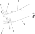
- FIG. 3 shows a cross-section of an inner portion 120 of a barrier 100 in a first closed position (v).
- the position (v) defines the condition of the barrier when it is undisturbed only affected by gravity.
- FIG 3 furthermore shows the second part of the locking mechanism 105, being an obstacle for the second shutter 103 to pivot in the upstream direction 107, as the protrusion 105 encountering the top of the support structure 101, the shape and size of the protrusion 105 defining the first closed position (v).
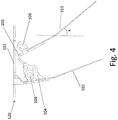
- FIG. 4 shows a cross-section of an inner portion 120 of a barrier 100 in a configuration where a second shutter 103 is locked by a locking mechanism 104 and 105 being in a second closed position (x).
- the position (x) defines the condition of the barrier 100 when it is disturbed by a vermin (not shown) tampering with the second shutter trying to pass the barrier.
- FIG. 4 furthermore shows a an inner portion 120 of barrier 100, wherein a second part of the locking mechanism 105, is intended to engage with a first part of the locking mechanism 104, when the second shutter 103 is tampered to be opened by a vermin, when the engagement of the first 104 and second part 105 of the locking mechanism takes effect, the protrusion 105 of the second shutter 103 will encounter the blocking mechanism 102 on or near the first shutter 102 and thereby only make a limited rotation of the second shutter possible, the rotation being limited so that the second shutter 103 cannot be opened or passed by a vermin from the upstream direction 107, the locking mechanism thereby ensure the second shutter 103 being kept in a closed position, the position being a second, closed position (x).
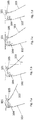
- FIG. 5 shows a cross-section of an inner portion 120 of a barrier 100 in a configuration where a first shutter 102 allows opening of a second shutter 103.
- the first shutter 102 is arranged for acting as an opener of the second shutter 103, the first shutter rotating towards the downstream 106 direction until engaging with the second shutter 103, thereby allowing the second shutter to rotate towards the downstream direction from a first, closed position (v) to a third, open position (w), so as to reduce damming of liquid in front of the barrier on the side facing the first shutter 102 by allowing a flow of liquid passing in a downstream direction 106 from the first shutter 102 towards the second shutter 103.
- FIG. 6 shows a cross-section of an inner portion 120 of a barrier 100 in a third opened position (w).
- the position (w) defines the condition of the barrier when a flow of liquid is passing in a downstream direction 106, cf. Figure 1 , from the first shutter 102 to the second shutter 103.
- FIG. 7a-d shows a cross-section of an inner portion 120 of a barrier 100 in a fourth partly opened position (z), wherein - when the first shutter 102 is in a closed position - the second part of the locking mechanism 105 is capable of passing the first part of the locking mechanism 104 so that the second shutter 103 is rotatable to a first, closed position (v).
- FIG. 8a-d shows cross-section of an inner part 120 a barrier 100 being reversible so that the definition of downstream 106 and upstream direction (107) can be reversed using the same barrier.
- the barrier 100 comprises a support structure 101 with a first hinge and a second hinge. Also, a first shutter 102 is pivotably mounted on the first hinge, and a second shutter 103 is pivotably mounted on the second hinge, and a locking mechanism comprising a first part 104 and a second part 105.
- FIG. 9a-b shows a click-on and a click-off function of the locking mechanism.
- the click-on/off functions are shown for the first locking mechanism for the blocking mechanism 104.
- the click-on/off functions could as well be applicable for the second locking mechanism 105. It is shown here, that the parts of the locking mechanism 104 and 105 without tolls, or with simple tools, can easily be attached and removed from the barrier 100, preferably on the site where the barrier is installed.
- FIG. 10a-b shows two different perspectives of a barrier 100 for installation in a sewage pipe.
- the invention relates to a barrier 100 suitable for installation in a sewage pipe and for preventing vermin from passing the barrier.
- the barrier comprising a support structure 101 with a first hinge 108 and a second hinge 109, a first shutter 102 pivotably mounted on the first hinge, a second shutter 103 pivotably mounted on the second hinge, and a locking mechanism comprising a first part 104 being a blocking mechanism, a second part 105 being formed as a protrusion.
- the locking mechanism is provided for keeping the second shutter 103 in a closed position, when the second shutter is tampered with by a vermin, e.g. a rat, trying to pass the barrier.
- This vermin barrier has the advantage of being reliable for preventing any vermin to pass the barrier, as the locking system within the barrier has a very optimal locking effect.
Landscapes
- Health & Medical Sciences (AREA)
- Life Sciences & Earth Sciences (AREA)
- Engineering & Computer Science (AREA)
- Hydrology & Water Resources (AREA)
- Public Health (AREA)
- Water Supply & Treatment (AREA)
- Catching Or Destruction (AREA)
Priority Applications (1)
| Application Number | Priority Date | Filing Date | Title |
|---|---|---|---|
| EP19174629.6A EP3739136A1 (fr) | 2019-05-15 | 2019-05-15 | Barrière contre la vermine avec mécanisme de verrouillage |
Applications Claiming Priority (1)
| Application Number | Priority Date | Filing Date | Title |
|---|---|---|---|
| EP19174629.6A EP3739136A1 (fr) | 2019-05-15 | 2019-05-15 | Barrière contre la vermine avec mécanisme de verrouillage |
Publications (1)
| Publication Number | Publication Date |
|---|---|
| EP3739136A1 true EP3739136A1 (fr) | 2020-11-18 |
Family
ID=66554254
Family Applications (1)
| Application Number | Title | Priority Date | Filing Date |
|---|---|---|---|
| EP19174629.6A Pending EP3739136A1 (fr) | 2019-05-15 | 2019-05-15 | Barrière contre la vermine avec mécanisme de verrouillage |
Country Status (1)
| Country | Link |
|---|---|
| EP (1) | EP3739136A1 (fr) |
Cited By (2)
| Publication number | Priority date | Publication date | Assignee | Title |
|---|---|---|---|---|
| US11470838B2 (en) * | 2017-10-03 | 2022-10-18 | Sewatech Aps | Rat and vermin barrier suitable for installation in a sewage pipe |
| WO2022229306A1 (fr) * | 2021-04-28 | 2022-11-03 | Urban Water Solution A/S | Dispositif de soupape servant à empêcher le reflux dans un canal d'écoulement d'un égout et le passage des rongeurs en amont dudit canal d'écoulement |
Citations (6)
| Publication number | Priority date | Publication date | Assignee | Title |
|---|---|---|---|---|
| DE699005C (de) * | 1938-10-28 | 1940-11-21 | Henry Nowak | In ein Kanalstueck einzusetzende Rattensperre |
| WO2006053562A1 (fr) * | 2004-11-18 | 2006-05-26 | Christian Thiim | Dispositif empêchant la pénétration des rongeurs |
| EP1826326A2 (fr) | 2006-02-27 | 2007-08-29 | Nordisk Innovation ApS | Barrière pour empêcher les rats ou autres animaux indésirables d'entrer dans un système de tuyau pour eaux usées |
| EP2113615A1 (fr) | 2008-03-05 | 2009-11-04 | Nordisk Innovation ApS | Barrière bidirectionelle pour empêcher les rats ou autres animaux indésirables d'entrer dans un système de tuyau pour eaux usées |
| US8459298B1 (en) * | 2006-03-09 | 2013-06-11 | Free Flow Products, LLC | Check valve for drain pipes |
| WO2019068301A1 (fr) | 2017-10-03 | 2019-04-11 | Sewatech Aps | Barrière contre les rats et la vermine convenant à une installation dans un tuyau d'égout |
-
2019
- 2019-05-15 EP EP19174629.6A patent/EP3739136A1/fr active Pending
Patent Citations (6)
| Publication number | Priority date | Publication date | Assignee | Title |
|---|---|---|---|---|
| DE699005C (de) * | 1938-10-28 | 1940-11-21 | Henry Nowak | In ein Kanalstueck einzusetzende Rattensperre |
| WO2006053562A1 (fr) * | 2004-11-18 | 2006-05-26 | Christian Thiim | Dispositif empêchant la pénétration des rongeurs |
| EP1826326A2 (fr) | 2006-02-27 | 2007-08-29 | Nordisk Innovation ApS | Barrière pour empêcher les rats ou autres animaux indésirables d'entrer dans un système de tuyau pour eaux usées |
| US8459298B1 (en) * | 2006-03-09 | 2013-06-11 | Free Flow Products, LLC | Check valve for drain pipes |
| EP2113615A1 (fr) | 2008-03-05 | 2009-11-04 | Nordisk Innovation ApS | Barrière bidirectionelle pour empêcher les rats ou autres animaux indésirables d'entrer dans un système de tuyau pour eaux usées |
| WO2019068301A1 (fr) | 2017-10-03 | 2019-04-11 | Sewatech Aps | Barrière contre les rats et la vermine convenant à une installation dans un tuyau d'égout |
Cited By (2)
| Publication number | Priority date | Publication date | Assignee | Title |
|---|---|---|---|---|
| US11470838B2 (en) * | 2017-10-03 | 2022-10-18 | Sewatech Aps | Rat and vermin barrier suitable for installation in a sewage pipe |
| WO2022229306A1 (fr) * | 2021-04-28 | 2022-11-03 | Urban Water Solution A/S | Dispositif de soupape servant à empêcher le reflux dans un canal d'écoulement d'un égout et le passage des rongeurs en amont dudit canal d'écoulement |
Similar Documents
| Publication | Publication Date | Title |
|---|---|---|
| US7988544B2 (en) | Bird/animal restricting vent for fluid/air discharge conduits | |
| EP2113615B1 (fr) | Barrière bidirectionelle pour empêcher les rats ou autres animaux indésirables d'entrer dans un système de tuyau pour eaux usées | |
| EP3739136A1 (fr) | Barrière contre la vermine avec mécanisme de verrouillage | |
| US10837177B2 (en) | Check valve for downspouts | |
| US8277645B2 (en) | Automatic retractable screen system for storm drain inlets | |
| EP0422934B1 (fr) | Fenêtre de sécurité effaçable | |
| US8033900B2 (en) | Low profile animal restricting vent for fluid discharge conduits | |
| US10227768B2 (en) | Resistance screens for use in storm drain filtration systems | |
| US9279242B2 (en) | Drain grate system and method | |
| US20090236293A1 (en) | Drain grate system and methods | |
| JP2002524674A (ja) | 下水溝の逆流防止装置 | |
| KR101860890B1 (ko) | 그레이팅의 이물질 유입방지 및 악취 차단장치 | |
| US10094099B1 (en) | Dual action retractable screen to be mounted to a curb inlet | |
| KR20150118000A (ko) | 악취차단용 빗물받이 및 그를 가지는 맨홀용 악취차단장치 | |
| US3955596A (en) | Sewer pest control check valve | |
| EP1826326B1 (fr) | Barrière pour empêcher les rats ou autres animaux indésirables d'entrer dans un système de tuyau pour eaux usées | |
| KR102057994B1 (ko) | 도로용 배수구 트랩 | |
| US3289840A (en) | Cover for drainage tiles | |
| US20150101969A1 (en) | Automatically retractable screens for storm drain curb inlets | |
| EP2933392A1 (fr) | Barrière de rat dotée d'obturateurs dentés et lisses | |
| US6109297A (en) | Directional drain valve | |
| EP4086399B1 (fr) | Barrière pour installation dans un système d'eaux usées à espace limité | |
| JP3747288B2 (ja) | 雨水ます用防臭装置 | |
| KR100614912B1 (ko) | 하수도용 커버 | |
| KR101311379B1 (ko) | 맨홀용 악취차단장치 |
Legal Events
| Date | Code | Title | Description |
|---|---|---|---|
| PUAI | Public reference made under article 153(3) epc to a published international application that has entered the european phase |
Free format text: ORIGINAL CODE: 0009012 |
|
| STAA | Information on the status of an ep patent application or granted ep patent |
Free format text: STATUS: THE APPLICATION HAS BEEN PUBLISHED |
|
| AK | Designated contracting states |
Kind code of ref document: A1 Designated state(s): AL AT BE BG CH CY CZ DE DK EE ES FI FR GB GR HR HU IE IS IT LI LT LU LV MC MK MT NL NO PL PT RO RS SE SI SK SM TR |
|
| AX | Request for extension of the european patent |
Extension state: BA ME |
|
| STAA | Information on the status of an ep patent application or granted ep patent |
Free format text: STATUS: REQUEST FOR EXAMINATION WAS MADE |
|
| 17P | Request for examination filed |
Effective date: 20210512 |
|
| RBV | Designated contracting states (corrected) |
Designated state(s): AL AT BE BG CH CY CZ DE DK EE ES FI FR GB GR HR HU IE IS IT LI LT LU LV MC MK MT NL NO PL PT RO RS SE SI SK SM TR |
|
| STAA | Information on the status of an ep patent application or granted ep patent |
Free format text: STATUS: EXAMINATION IS IN PROGRESS |
|
| 17Q | First examination report despatched |
Effective date: 20220831 |