EP3739112A1 - Defibration treatment apparatus and fiber processing apparatus - Google Patents
Defibration treatment apparatus and fiber processing apparatus Download PDFInfo
- Publication number
- EP3739112A1 EP3739112A1 EP20163802.0A EP20163802A EP3739112A1 EP 3739112 A1 EP3739112 A1 EP 3739112A1 EP 20163802 A EP20163802 A EP 20163802A EP 3739112 A1 EP3739112 A1 EP 3739112A1
- Authority
- EP
- European Patent Office
- Prior art keywords
- rotator
- treatment apparatus
- screen
- fixed member
- discharge path
- Prior art date
- Legal status (The legal status is an assumption and is not a legal conclusion. Google has not performed a legal analysis and makes no representation as to the accuracy of the status listed.)
- Granted
Links
Images


Classifications
-
- D—TEXTILES; PAPER
- D21—PAPER-MAKING; PRODUCTION OF CELLULOSE
- D21B—FIBROUS RAW MATERIALS OR THEIR MECHANICAL TREATMENT
- D21B1/00—Fibrous raw materials or their mechanical treatment
- D21B1/04—Fibrous raw materials or their mechanical treatment by dividing raw materials into small particles, e.g. fibres
- D21B1/06—Fibrous raw materials or their mechanical treatment by dividing raw materials into small particles, e.g. fibres by dry methods
- D21B1/063—Fibrous raw materials or their mechanical treatment by dividing raw materials into small particles, e.g. fibres by dry methods using grinding devices
-
- D—TEXTILES; PAPER
- D21—PAPER-MAKING; PRODUCTION OF CELLULOSE
- D21B—FIBROUS RAW MATERIALS OR THEIR MECHANICAL TREATMENT
- D21B1/00—Fibrous raw materials or their mechanical treatment
- D21B1/04—Fibrous raw materials or their mechanical treatment by dividing raw materials into small particles, e.g. fibres
- D21B1/06—Fibrous raw materials or their mechanical treatment by dividing raw materials into small particles, e.g. fibres by dry methods
- D21B1/061—Fibrous raw materials or their mechanical treatment by dividing raw materials into small particles, e.g. fibres by dry methods using cutting devices
-
- D—TEXTILES; PAPER
- D21—PAPER-MAKING; PRODUCTION OF CELLULOSE
- D21B—FIBROUS RAW MATERIALS OR THEIR MECHANICAL TREATMENT
- D21B1/00—Fibrous raw materials or their mechanical treatment
- D21B1/04—Fibrous raw materials or their mechanical treatment by dividing raw materials into small particles, e.g. fibres
- D21B1/06—Fibrous raw materials or their mechanical treatment by dividing raw materials into small particles, e.g. fibres by dry methods
- D21B1/08—Fibrous raw materials or their mechanical treatment by dividing raw materials into small particles, e.g. fibres by dry methods the raw material being waste paper; the raw material being rags
-
- D—TEXTILES; PAPER
- D04—BRAIDING; LACE-MAKING; KNITTING; TRIMMINGS; NON-WOVEN FABRICS
- D04H—MAKING TEXTILE FABRICS, e.g. FROM FIBRES OR FILAMENTARY MATERIAL; FABRICS MADE BY SUCH PROCESSES OR APPARATUS, e.g. FELTS, NON-WOVEN FABRICS; COTTON-WOOL; WADDING ; NON-WOVEN FABRICS FROM STAPLE FIBRES, FILAMENTS OR YARNS, BONDED WITH AT LEAST ONE WEB-LIKE MATERIAL DURING THEIR CONSOLIDATION
- D04H1/00—Non-woven fabrics formed wholly or mainly of staple fibres or like relatively short fibres
- D04H1/70—Non-woven fabrics formed wholly or mainly of staple fibres or like relatively short fibres characterised by the method of forming fleeces or layers, e.g. reorientation of fibres
- D04H1/72—Non-woven fabrics formed wholly or mainly of staple fibres or like relatively short fibres characterised by the method of forming fleeces or layers, e.g. reorientation of fibres the fibres being randomly arranged
- D04H1/732—Non-woven fabrics formed wholly or mainly of staple fibres or like relatively short fibres characterised by the method of forming fleeces or layers, e.g. reorientation of fibres the fibres being randomly arranged by fluid current, e.g. air-lay
-
- D—TEXTILES; PAPER
- D21—PAPER-MAKING; PRODUCTION OF CELLULOSE
- D21F—PAPER-MAKING MACHINES; METHODS OF PRODUCING PAPER THEREON
- D21F9/00—Complete machines for making continuous webs of paper
- D21F9/04—Complete machines for making continuous webs of paper of the cylinder type
-
- Y—GENERAL TAGGING OF NEW TECHNOLOGICAL DEVELOPMENTS; GENERAL TAGGING OF CROSS-SECTIONAL TECHNOLOGIES SPANNING OVER SEVERAL SECTIONS OF THE IPC; TECHNICAL SUBJECTS COVERED BY FORMER USPC CROSS-REFERENCE ART COLLECTIONS [XRACs] AND DIGESTS
- Y02—TECHNOLOGIES OR APPLICATIONS FOR MITIGATION OR ADAPTATION AGAINST CLIMATE CHANGE
- Y02W—CLIMATE CHANGE MITIGATION TECHNOLOGIES RELATED TO WASTEWATER TREATMENT OR WASTE MANAGEMENT
- Y02W30/00—Technologies for solid waste management
- Y02W30/50—Reuse, recycling or recovery technologies
- Y02W30/64—Paper recycling
Definitions
- the present disclosure relates to a defibration treatment apparatus and a fiber processing apparatus.
- a material is introduced through an introduction opening and is discharged through a discharge opening after the material has been defibrated between inner blades provided on an outer circumference of a rotator, and outer blades provided on an inner circumference of a fixed member.
- defibration is performed by inner blades of a rotator disposed between an introduction opening and a discharge opening in a rotation shaft direction, and outer blades of a fixed member that covers the rotator in the entire rotation shaft direction.
- a defibration treatment apparatus including a feeding hole through which a material is fed, a rotator that rotates about a rotational central axis, a fixed member that covers at least a portion of the rotator, and a discharge opening that discharges a defibrated object obtained by defibrating the material between the rotator and the fixed member, in which the rotator includes a plurality of rotary blades that extend in directions away from the rotational central axis, in which at least a portion of the fixed member is configured of a screen including a plurality of openings, in which the screen is disposed at a position corresponding to an outer rotational circumference of the rotator, and in which a discharge path in communication with the discharge opening is provided along the screen and on a side opposite the rotator with respect to the screen.
- a cross-sectional area of the discharge path at a first position that is close to the discharge opening may be larger than a cross-sectional area of the discharge path at a second position that is farther away from the discharge opening than the first position.
- the discharge path may be, at a position away from the discharge opening, coupled to an air suction path configured to take in a gas.
- an air sending device that sends a gas from the discharge path to the air suction path may be coupled to the discharge path.
- Another aspect overcoming the above issue is a fiber processing apparatus including the defibration treatment apparatus according to the above, and a processing portion that processes a defibrated object defibrated in the defibration treatment apparatus.
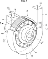
- FIG. 1 is a perspective view of a defibration treatment apparatus 20.
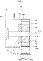
- FIG. 2 is a cross-sectional view taken along line II-II in FIG. 1 .
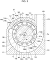
- FIG. 3 is a cross-sectional view taken along line III-III in FIG. 1 .
- the defibration treatment apparatus 20 is an apparatus that performs a treatment in which a material MA in which a plurality of fibers are bound together is unbound into a single or a few fibers.
- the defibration treatment apparatus 20 is a dry defibration treatment apparatus that performs processes such as defibration in gas, such as the atmosphere or air, rather than in liquid.
- the defibration treatment apparatus 20 includes a rotationally driven rotator 160 and a fixed member 140 that covers the surroundings of the rotator 160.
- the defibration treatment apparatus 20 further includes a housing 180 that covers and houses the rotator 160 and the fixed member 140. In FIG. 1 , illustration of the housing 180 is omitted and an internal structure of the defibration treatment apparatus 20 is illustrated.
- a configuration in which a rotation shaft 171 extends in the horizontal direction will be described in the present exemplary embodiment.
- the rotation shaft 171 of the rotator 160 may be configured to extend in the gravitational direction.
- the rotation shaft 171 may be configured to extend in any direction and rotate thereat.
- the direction in which the rotation shaft 171 extends will be referred to as an axial direction.
- a center of a rotator shape, such as the rotator 160, in the radial direction will be referred to as a shaft center 110.
- the housing 180 includes a cylindrically shaped body portion 181.
- a defibration chamber 183 is formed by an internal space of the body portion 181.
- a cylindrical portion 184 that extends in the axial direction is formed on one end side of the body portion 181 in the axial direction.
- An inner portion of the cylindrical portion 184 is in communication with the defibration chamber 183.
- An inlet pipe portion 191 is formed in the upper portion of the cylindrical portion 184.
- the upper portion corresponds to an example of a direction that intersects the axial direction.
- An internal space of the inlet pipe portion 191 is in communication with the defibration chamber 183 through the cylindrical portion 184.
- a feeding hole 192 that is open upwards is formed at an upper end of the inlet pipe portion 191. The material MA fed through the feeding hole 192 moves to the defibration chamber 183 through the inlet pipe portion 191.
- the rotator 160 is disposed in the defibration chamber 183 of the housing 180.
- the rotator 160 includes the rotation shaft 171 that extends in the horizontal direction and a rotator body 161 that is fixed to and supported by the rotation shaft 171.
- the rotator body 161 includes a columnar base portion 162 through which the rotation shaft 171 is inserted, and defibration inner blades 163 that radially protrude from an outer circumference side of the base portion 162.
- Each defibration inner blade 163 is configured of a plate-shaped protrusion extending in the axial direction.
- a plurality of defibration inner blades 163 are formed in the circumferential direction with gaps in between.
- the defibration inner blades 163 correspond to an example of a plurality of rotary blades that protrude in directions extending away from the rotation shaft 171.
- a shaft hole 161a is formed in the center of the rotator body 161.
- a vane plate 167 is attached to the feeding hole 192 side of the rotator 160 in the axial direction.
- a plurality of vanes 167a are provided on a surface of the vane plate 167 on the inlet pipe portion 191 side.
- the vanes 167a function, at the least, to move the material MA from the inlet pipe portion 191 side towards the other end side in the axial direction when the rotator 160 is rotated.
- the rotator 160 includes the rotation shaft 171, the rotator body 161, and the vane plate 167. Note that while the rotator body 161 has been described as an integrally formed block, the rotator body 161 may be configured of plates stacked on each other.
- the rotation shaft 171 of the rotator 160 is rotatably supported by the housing 180.
- the rotation shaft 171 is rotationally driven by a drive mechanism (not shown).
- the drive mechanism is configured of a belt and a pulley, and the rotation shaft 171 is driven by having motive power from a rotary drive source (not shown) transmitted to the belt and the pulley.
- a rotary drive source not shown
- the configuration that rotationally drives the rotation shaft 171 does not have to be configured of a belt and a pulley.
- the rotation shaft 171 is configured to rotate in a rotation direction illustrated by an arrow C1 in FIG. 3 .
- the fixed member 140 is disposed on the outer side of the rotator 160 in the radial direction so as to cover an outer circumference of the rotator 160.
- the fixed member 140 is supported by the housing 180.
- the fixed member 140 is a member configured in a cylindrical manner extending along an outer rotational circumference of the rotator 160.
- the fixed member 140 is disposed in a concentric manner so as to surround the rotator 160 and form a gap G (see FIG. 3 ) around the rotator 160.
- the fixed member 140 of the present exemplary embodiment includes a fixed outer blade 150 and a screen 155 that are provided in the circumferential direction.
- the fixed outer blade 150 corresponds to an example of a fixed blade.
- the fixed outer blade 150 is disposed in a portion of the housing 180.
- Defibration outer blades 152 that protrude in the radial direction in a mountainous shape are formed on an inner circumferential portion of a block portion 151.
- the defibration outer blades 152 are formed at equal intervals in the circumferential direction.
- the defibration outer blades 152 form a protruding and recessed shape in the circumferential direction.
- apex portions 152a and valley portions 152b extend in the axial direction in a stripe like manner.
- the screen 155 is configured of metal plate materials 156, for example.
- the screen 155 is configured of the plate materials 156 combined in the rotation direction C1 of the rotator 160.
- the plate materials 156 are fixed with frames 186b.
- a plurality of openings are formed in each plate material 156 by a method such as, for example, punching, etching, or cutting.
- the plate material 156 may be a mesh formed by weaving wires.
- a plurality of circular hole-shaped classification holes 156a that penetrate the plate material 156 in the thickness direction are formed.
- the fixed member 140 is configured of the fixed outer blade 150 and the screen 155 combined in the rotation direction of the rotator 160.
- the fixed member 140 corresponds to an example of a connection body.
- a discharge path 121 is formed on the outer side of the plate material 156 in the radial direction.
- the discharge path 121 is a hollow hole.
- the discharge path 121 includes a bent portion 122 that extends along an outer circumferential portion of the screen 155.
- a rectilinear portion 123 that extends from the fixed member 140 is formed downstream of the bent portion 122 in the rotation direction C1.
- a downstream end of the rectilinear portion 123 is open to the outside.
- a discharge opening 124 corresponding to the downstream end of the rectilinear portion 123 is formed in the housing 180.
- a diameter enlarged portion 187 is formed on the outer side of the body portion 181 in the radial direction.
- the discharge path 121 serving as a space is formed on the outer circumferential side of the fixed member 140 by separating the body portion 181 of the housing 180 and the internal space of the diameter enlarged portion 187 from each other with the fixed member 140.
- the housing 180 includes, in the diameter enlarged portion 187, an inner wall surface 180A and lateral-wall inner wall surfaces 180B and 180C that stand up from both ends of the inner wall surface 180A in the width direction or both ends of the inner wall surface 180A in the axial direction.
- the inner wall surface 180A is formed so that the distance from the screen 155 becomes larger as the inner wall surface 180A extends in the rotation direction of the rotator 160. Accordingly, the bent portion 122 of the discharge path 121 is formed so that a cross-sectional area Sa of the discharge path 121 becomes larger as the discharge path 121 extends downstream in the rotation direction C1.
- the cross-sectional area Sa is an area of a cross section taken in a direction normal to the screen 155.
- the discharge path 121 is in communication with a space inside the fixed member 140 through the classification holes 156a of the plate materials 156.
- a defibrated object that has been defibrated by the fixed member 140 and the rotator 160 can be discharged into the discharge path 121 through the plurality of classification holes 156a of the screen 155 that are provided in the axial direction.
- the defibration treatment apparatus 20 performs a dry defibration treatment on the material MA by rotating the rotator 160 by rotating the rotation shaft 171, and by guiding the material MA through the gap G between the rotator 160 and the fixed member 140 with airflow.
- the material MA fed through the feeding hole 192 of the defibration treatment apparatus 20 is introduced into an inner portion of the housing 180 through the inlet pipe portion 191.
- the rotator 160 is rotated in the inner portion of the housing 180, and the material MA is sent to the gap G between the defibration inner blades 163 of the rotator 160 and the fixed member 140.
- the material MA that has been sent into the gap G and that has received centrifugal force from the rotator 160 flies through the gap G, impinges on the fixed member 140, is unbound, and becomes defibrated.
- a configuration in which the rotator is disposed between the introduction opening and the discharge opening in the axial direction and in which the defibration outer blades of the fixed member are disposed and formed so as to cover the outer circumferences of the defibration inner blades of the rotator in the entire rotation shaft direction can be conceived.
- the airflow created by the rotation of the rotator impinges on the inner surfaces of the defibration outer blades and becomes diffused, and the airflow in the defibration outer blades tends to become stagnated; accordingly, the defibrated object tends to become stagnated on the discharge opening side in a portion between the rotator and the fixed member.
- the screen 155 is provided in the outer circumferential direction of the rotator 160. Furthermore, the discharge path 121 is provided on a side opposite the rotator 160 with respect to the screen 155. Accordingly, the airflow easily flows to the discharge path 121 through the classification holes 156a of the screen 155 and the airflow between the fixed member 140 and the rotator 160 becomes stabilized easily. Due to the above, the defibrated object on the stable airflow easily passes through the classification holes 156a and stagnation of the defibrated object between the fixed member 140 and the rotator 160 is suppressed.
- the cross-sectional area Sa on the discharge opening 124 side is larger than that of the upstream portion. Note that since the airflow and the defibrated object can enter the discharge path 121 sequentially from the upstream portion across to the downstream portion, when the cross-sectional area Sa is small in the downstream portion of the discharge path 121, there are cases in which the pressure in the discharge path 121 becomes excessively high. As a result, the flow rate of the airflow passing through the classification holes 156a in the upstream portion tends to decrease, and the defibrated object tends to stagnate in the upstream portion between the fixed member 140 and the rotator 160.
- the cross-sectional area Sa becomes larger as the bent portion 122 of the discharge path 121 extends downstream and the velocity of the airflow can be obtained in the upstream portion between the fixed member 140 and the rotator 160; accordingly, discharge of the defibrated object through the fixed member 140 is facilitated.
- the defibration treatment apparatus 20 of the present exemplary embodiment includes the feeding hole 192 through which the material MA is fed, the rotator 160 that rotates about the rotation shaft 171, and the fixed member 140 that covers the rotator 160.
- the defibration treatment apparatus 20 further includes the discharge opening 124 through which the defibrated object obtained by defibrating the material MA between the rotator 160 and the fixed member 140 is discharged.
- the rotator 160 includes the plurality of defibration inner blades 163 that protrude in directions extending away from the rotation shaft 171.
- at least a portion of the fixed member 140 is configured of the screen 155 including the plurality of classification holes 156a.
- the screen 155 is disposed at a position corresponding to the outer rotational circumference of the rotator 160. Furthermore, the discharge path 121 that is in communication with the discharge opening 124 is provided along the screen 155 and on a side opposite the rotator 160 with respect to the screen 155. Accordingly, since the discharge path 121 is provided downstream in the rotation direction C1 of the defibration inner blades 163, the airflow does not become stagnated and the airflow can be oriented towards the discharge opening 124. Accordingly, stagnation of the defibrated object between the rotator 160 and the fixed member 140 can be suppressed.
- the discharge path 121 is shaped so that the cross-sectional area Sa thereof at a downstream position that is near the discharge opening 124 is larger than the cross-sectional area Sa thereof at an upstream position that is farther away from the discharge opening 124 than the downstream position.
- the airflow from inside the fixed member 140 tends to have a smaller flow rate in a portion upstream in the rotation direction C1 of the defibration inner blades 163.
- the velocity of the airflow in the discharge path 121 becomes faster, which facilitates the discharge of the defibrated object from inside the fixed member 140.
- FIG. 4 is a perspective view of a defibration treatment apparatus 220 of the second exemplary embodiment.
- FIG. 5 is a cross-sectional view of a portion including the discharge path 121 and the rotator 160 in FIG. 4 taken along the rotation direction of the rotator 160 (a cross-sectional view taken along line V-V). Note that FIG. 4 corresponds to FIG. 1 of the first exemplary embodiment, and FIG. 5 corresponds to FIG. 3 of the first exemplary embodiment.
- the defibration treatment apparatus 220 of the second exemplary embodiment includes a housing 280 that includes, other than the discharge path 121 and the discharge opening 124 included in the housing 180 of the first exemplary embodiment, an air suction path 238.
- the housing 280 of the second exemplary embodiment includes a suction air introducing pipe portion 193 at a position corresponding to an upstream end of the discharge path 121.
- An internal space of the suction air introducing pipe portion 193 is in communication with an upstream portion of the discharge path 121.
- the air suction path 238 is formed by the internal space of the suction air introducing pipe portion 193.
- a blower 239 is coupled to the air suction path 238.
- the blower 239 sends a gas from the air suction path 238 to the discharge path 121.
- the blower 239 corresponds to an example of an air sending device.
- the defibration treatment apparatus 220 of the second exemplary embodiment also has a configuration similar to that of the first exemplary embodiment. Since the discharge path 121 is provided downstream in the rotation direction C1 of the defibration inner blades 163, the airflow does not become stagnated and the airflow can be oriented towards the discharge opening 124. Accordingly, stagnation of the defibrated object can be suppressed.
- the air suction path 238 is coupled to the upstream end of the discharge path 121, and the blower 239 is coupled to the air suction path 238. Accordingly, a gas can be sent from the air suction path 238 to the discharge path 121 with the blower 239, and the flow velocity of the gas flowing towards the discharge opening 124 of the discharge path 121 can be increased. Accordingly, a discharge efficiency of the defibrated object in the discharge path 121 to the discharge opening 124 can be increased.
- the rotator 160 includes the plurality of defibration inner blades 163 that protrude in directions extending away from the rotation shaft 171. Furthermore, at least a portion of the fixed member 140 is configured of the screen 155 including the plurality of classification holes 156a. The screen 155 is disposed at a position corresponding to the outer rotational circumference of the rotator 160. Furthermore, the discharge path 121 that is in communication with the discharge opening 124 is provided along the screen 155 and on a side opposite the rotator 160 with respect to the screen 155. Accordingly, in the present exemplary embodiment as well, similar to the first exemplary embodiment, stagnation of the defibrated object between the rotator 160 and the fixed member 140 can be suppressed.
- the discharge path 121 is, at a position away from the discharge opening 124, coupled to the air suction path 238 through which the gas can be taken in. Accordingly, depending on the gas that is taken in, the flow velocity of the gas in the discharge path 121 can be increased. Accordingly, a discharge efficiency of the defibrated object in the discharge path 121 to the discharge opening 124 can be increased.
- the blower 239 that sends a gas from the air suction path 238 to the discharge path 121 is coupled to the air suction path 238. Accordingly, since the gas is actively sent from the air suction path 238 into the discharge path 121, the flow velocity of the gas in the discharge path 121 can be increased further. Accordingly, a discharge efficiency of the defibrated object in the discharge path 121 to the discharge opening 124 can be increased.
- the cross-sectional area Sa at a downstream position that is near the discharge opening 124 is larger than the cross-sectional area Sa at an upstream position that is farther away from the discharge opening 124 than the downstream position. Accordingly, similar to the first exemplary embodiment, by reducing the cross-sectional area Sa of the discharge path 121 in the upstream portion, the velocity of the airflow in the upstream portion of the discharge path 121 becomes fast, which facilitates the discharge of the defibrated object.
- FIG. 6 is a cross-sectional view of a defibration treatment apparatus 620 of the third exemplary embodiment.
- the defibration treatment apparatus 620 includes a fixed member 640.
- the fixed member 640 of the present exemplary embodiment includes a screen 655 and a plate 650 that are provided in the circumferential direction of the rotator 160.
- the fixed member 640 is a drum configured in a columnar manner with a single or a plurality of plate materials, and includes a screen area (hereinafter, a first area) in which the plurality of classification holes (openings) 156a are provided and a plate 650 area (hereinafter, a second area) in which the classification holes (openings) 156a are not provided.
- the configuration is similar to that in FIG. 2 described above other than that the fixed outer blade 150 is replaced with the plate 650.
- the screen 655 configured of a metal plate material 156, for example, is provided and, in a similar manner, a metal plate 650, for example, is provided in the second area of the fixed member 640.
- the plate 650 is disposed on an upper portion of the fixed member 640. While the plate 650 is integrally assembled with the screen 655 in a columnar manner, the plate 650 is configured so that no classification holes 156a is formed. Furthermore, the screen 655 is disposed at least at a portion corresponding to where the discharge path 121 is provided.
- the material MA can be defibrated in the gap G between the rotator 160 and the plate materials 156.
- the defibration treatment apparatus 620 of the third exemplary embodiment is provided with the discharge path 121 from the upstream portion (from an upstream end 155A side) in the rotation direction C1 of the defibration inner blades 163 towards the downstream portion (a downstream end 155B side). Furthermore, since the discharge path 121 is disposed outside the position corresponding to the screen 655, the airflow can be oriented towards the discharge opening 124 without the airflow becoming stagnant. Accordingly, stagnation of the defibrated object can be suppressed.
- the material MA supplied through the feeding hole 192 is defibrated between the fixed member 640, which is a columnar drum, and the rotator 160 (the defibration inner blades 163).
- the material MA is defibrated in the gap G between the rotator 160 and the plate materials 156. Accordingly, the material MA that has passed the gap G can be defibrated between the plate materials 156 and the defibration inner blades 163.
- the material MA is defibrated between the fixed member 640, which is a columnar drum, and the defibration inner blades 163 of the rotator 160 until the material MA is defibrated to a size that passes through the classification holes 156a (the openings) provided in the screen 655. Furthermore, the defibrated object that has passed through the classification holes 156a (the openings) of the screen 655 is output to the discharge path 121 provided along the outer circumference of the screen 655. The defibrated object that has been output to the discharge path 121 through the classification holes 156a (openings) of the screen 655 is, as described above, transported towards the discharge opening 124 with the airflow.
- the inner wall surface 180A is formed so that the distance from the screen 155 becomes larger as the inner wall surface 180A extends in the rotation direction C1 of the rotator 160. Accordingly, the bent portion 122 of the discharge path 121 is formed so that a cross-sectional area Sa of the discharge path 121 becomes larger as the discharge path 121 extends downstream in the rotation direction C1. Similar to the second exemplary embodiment, the present exemplary embodiment may also be configured to include an air suction path 238 in the upstream portion of the discharge path 121, which will have an advantageous effect similar to that of the second exemplary embodiment.
- the rotator 160 includes the plurality of defibration inner blades 163 that protrude in directions extending away from the rotation shaft 171.
- the fixed member 640 is configured of the screen 655 including the plurality of classification holes 156a.
- the screen 655 is disposed at a position corresponding to the outer rotational circumference of the rotator 160.
- the discharge path 121 that is in communication with the discharge opening 124 is provided along the screen 655 and on a side opposite the rotator 160 with respect to the screen 655. Accordingly, in the present exemplary embodiment as well, similar to the first exemplary embodiment, stagnation of the defibrated object between the rotator 160 and the fixed member 640 can be suppressed.
- FIG. 7 is a schematic diagram illustrating a configuration of a sheet manufacturing apparatus 100.
- the sheet manufacturing apparatus 100 fiberizes the material MA containing fiber, and performs a reproducing process that reproduces a new sheet S.
- the sheet manufacturing apparatus 100 corresponds to an example of a fiber processing apparatus.
- the sheet manufacturing apparatus 100 includes a storing and supplying portion 10, a shredding portion 12, a defibrating portion 520, a screening portion 40, a first web forming portion 45, a rotator 49, a mixing portion 50, an accumulating portion 60, a second web forming portion 70, a transporting portion 79, a sheet forming portion 80, and a cutting portion 90.
- the defibrating portion 520 of the sheet manufacturing apparatus 100 includes the defibration treatment apparatus 20 of the first exemplary embodiment.
- the screening portion 40, the first web forming portion 45, the rotator 49, the mixing portion 50, the accumulating portion 60, the second web forming portion 70, the transporting portion 79, the sheet forming portion 80, and the cutting portion 90 each corresponds to a processing portion that processes the defibrated object that has been defibrated by the defibration treatment apparatus.
- the storing and supplying portion 10 stores the material MA and is an automatic feeding apparatus that continuously feeds the material MA to the shredding portion 12.
- the material MA may be any material that contains fiber and is wastepaper, disposed paper, or a pulp sheet, for example.
- the shredding portion 12 includes shredding blades 14 that cuts the material MA supplied by the storing and supplying portion 10.
- the shredding portion 12 cuts the material MA into pieces of a few square centimeters in midair with the shredding blades 14.
- the shredding portion 12 can use a shredder, for example.
- the material MA cut by the shredding portion 12 is collected with a hopper 9 and is transported to the feeding hole 192 (see FIG. 2 ) of the defibrating portion 520 through a pipe 2.
- Shredded pieces are transported from the shredding portion 12 to the defibrating portion 520 with the airflow.
- the shredded pieces are fed thereto through the feeding hole 192, and the shredded pieces are defibrated between the rotator 160 and the fixed member 140.
- the defibrated shredded pieces, or the defibrated object is output through the discharge opening 124.
- the defibrated object is transported from the defibrating portion 520, through a pipe 3 coupled to the discharge opening 124 (see FIG. 3 ), and to the screening portion 40 with the airflow.
- the screening portion 40 screens the constituents included in the defibrated object based on fiber size.
- the screening portion 40 includes a drum portion 41 and a housing portion 43 that houses the drum portion 41.
- a sieve for example, is used as the drum portion 41.
- the defibrated object introduced into an inner portion of the drum portion 41 through an introduction opening 42 is separated, with the rotation of the drum portion 41, into a passing object that passes through the opening of the drum portion 41 and a remaining object that does not pass through the opening.
- a first screened object which is the passing object that has passed through the opening, descends through an inner portion inside the housing portion 43 towards the first web forming portion 45.
- a second screened object which is the remaining object that does not pass through the opening, is resent to the feeding hole 192 of the defibrating portion 520 through a pipe 8 from a discharge opening 44 that is in communication with the inner portion of the drum portion 41.
- the first web forming portion 45 includes a mesh belt 46, stretching rollers 47, and a suction portion 48.
- the mesh belt 46 is an endless belt stretched across the plurality of stretching rollers 47.
- the mesh belt 46 circulates through a route formed by the stretching rollers 47. A portion of the route of the mesh belt 46 under the drum portion 41 is flat.
- the mesh belt 46 forms a flat surface.
- the suction portion 48 corresponds to a suction mechanism.
- a plurality of openings are formed in the mesh belt 46.
- the constituents that are larger than the openings of the mesh belt 46 are accumulated on the mesh belt 46.
- the constituents that are smaller than the openings of the mesh belt 46 pass through the openings.
- the suction portion 48 includes a blower (not shown) and suctions the air from a side opposite the drum portion 41 with respect to the mesh belt 46.
- the constituents that pass through the openings of the mesh belt 46 are suctioned into the suction portion 48.
- the airflow that is suctioned by the suction portion 48 draws the first screened objects descending from the drum portion 41 to the mesh belt 46, which has an effect of facilitating accumulation of the first screened objects.
- the constituents that have accumulated on the mesh belt 46 is formed into a web shape so as to constitute a first web W1.
- the basic configurations of the mesh belt 46, the stretching rollers 47, and the suction portion 48 are similar to those of a mesh belt 72, the stretching rollers 74, and the suction mechanism 76 of the second web forming portion 70 described later.
- the mesh belt 46 moves, the first web W1 is transported to the rotator 49.
- the rotator 49 includes a base portion 49a that is coupled to a drive portion (not shown) of a motor or the like, and a protrusion 49b that protrudes from the base portion 49a. By having the base portion 49a rotate in a D direction, the protrusion 49b is rotated about the base portion 49a.
- the rotator 49 is positioned at an end portion of the flat portion in the route of the mesh belt 46. Since the route of the mesh belt 46 bends downwards in the above end portion, the first web W1 transported by the mesh belt 46 protrudes from the mesh belt 46 and comes in contact with the rotator 49. The first web W1 becomes unbound by the protrusion 49b impinging thereon, and the first web W1 becomes small pieces of fibers. The above pieces pass through a pipe 7 positioned under the rotator 49 and are transported to the mixing portion 50.
- the mixing portion 50 mixes the first screened object and an additive with each other.
- the mixing portion 50 includes an additive supplying portion 52 that supplies the additive, a pipe 54 that transports the first screened object and the additive, and a mixing blower 56.
- the additive supplying portion 52 supplies the additive formed of fine powder or fine particles inside an additive cartridge 52a to the pipe 54.
- the additive suppled from the additive supplying portion 52 contains a resin, or a binding agent, that binds a plurality of fibers to each other.
- the resin contained in the additive becomes melted when passing through the sheet forming portion 80 and binds the plurality of fibers to each other.
- the mixing blower 56 generates airflow in the pipe 54 that couples the pipe 7 and the accumulating portion 60 to each other. Furthermore, the first screened object transported from the pipe 7 to the pipe 54, and the additive suppled to the pipe 54 from the additive supplying portion 52 are mixed when passing through the mixing blower 56.
- the accumulating portion 60 unbinds the fibers in the mixture and disperses the fibers in the air while the fibers descend to the second web forming portion 70.
- the accumulating portion 60 includes a drum portion 61 and a housing portion 63 that houses the drum portion 61.
- the drum portion 61 is a cylindrical structure configured in a manner similar to the drum portion 41, is rotated by motive power of a motor (not shown) in a manner similar to the drum portion 41, and functions as a sieve.
- the second web forming portion 70 is disposed under the drum portion 61.
- the second web forming portion 70 includes, for example, the mesh belt 72, the stretching rollers 74, and the suction mechanism 76.
- the constituents that are larger than the openings of the mesh belt 72 are accumulated on the mesh belt 72.
- the constituents that have accumulated on the mesh belt 72 is formed into a web shape so as to constitute a second web W2.
- a humidity control portion 78 is provided downstream of the accumulating portion 60 in the transport path of the mesh belt 72.
- the moisture amount in the second web W2 is controlled with the moisture supplied by the humidity control portion 78; accordingly, an effect of suppressing adhesion of the fiber to the mesh belt 72 caused by static electricity can be expected.
- the second web W2 is peeled off from the mesh belt 72 with the transporting portion 79 and is transported to the sheet forming portion 80.
- the transporting portion 79 includes, for example, a mesh belt 79a, rollers 79b, and a suction mechanism 79c.
- the suction mechanism 79c includes a blower (not shown) and generates an upwards airflow through the mesh belt 79a with suction force of the blower.
- the second web W2 is separated from the mesh belt 72 with the above airflow and is attached to the mesh belt 79a.
- the mesh belt 79a is moved by the rotation of the rollers 79b and transports the second web W2 to the sheet forming portion 80.
- the mesh belt 79a can be configured of an endless belt including openings in a manner similar to the mesh belt 46 and the mesh belt 72.
- the sheet forming portion 80 binds the fibers included in the second web W2 derived from the first screened object with the resin included in the additive.
- the sheet forming portion 80 includes a compressing portion 82 that compresses the second web W2, and a heating portion 84 that heats the second web W2 compressed by the compressing portion 82.
- the compressing portion 82 compresses the second web W2 at a predetermined nip pressure with calender rollers 85 and 85 and transports the second web W2 towards the heating portion 84.
- the heating portion 84 pinches and applies heat to the second web W2 that has been highly densified with a pair of heating rollers 86 and 86, and transports the second web W2 to the cutting portion 90.
- the resin included in the second web W2 is heated at the heating portion 84 and the second web W2 becomes a sheet S.
- the cutting portion 90 cuts the sheet S formed at the sheet forming portion 80.
- the cutting portion 90 includes a first cutting portion 92 that cuts the sheet S in a direction intersecting the transport direction of the sheet S depicted by a reference numeral F1 in the drawing, and a second cutting portion 94 that cuts the sheet S in a direction parallel to the transport direction F1.
- the cutting portion 90 cuts the sheet S into a length and a width of a predetermined size so as to form cut-form sheets S.
- the sheets S cut in the cutting portion 90 is stored in a discharge portion 96.
- the sheet manufacturing apparatus 100 of the present exemplary embodiment includes the defibrating portion 520, the screening portion 40 that performs a treatment on the defibrated object defibrated in the defibrating portion 520, the first web forming portion 45, the rotator 49, and the mixing portion 50.
- the sheet manufacturing apparatus 100 of the present exemplary embodiment further includes the accumulating portion 60, the second web forming portion 70, the transporting portion 79, the sheet forming portion 80, and the cutting portion 90.
- the discharge path 121 is provided in the defibrating portion 520 in a direction downstream of the rotation of the defibration inner blades 163 (see FIG. 3 ), the airflow does not become stagnated and can be oriented towards the discharge opening 124; accordingly, stagnation in the airflow can be prevented from occurring. Accordingly, since the defibrated object is supplied in a continuous and stable manner to the screening portion 40 that performs treatment on the defibrated object defibrated in the defibrating portion 520, the treatment of the fibers of the defibrated object becomes stable and a uniform sheet S can be obtained.
- the sheet S corresponds to an example of a fiber treated object.
- the defibrating portion 520 can be configured of either one of the defibration treatment apparatuses 220 and 620 of the second and third exemplary embodiment in place of the defibration treatment apparatus 20 of the first exemplary embodiment.
Landscapes
- Engineering & Computer Science (AREA)
- Life Sciences & Earth Sciences (AREA)
- Wood Science & Technology (AREA)
- Mechanical Engineering (AREA)
- Textile Engineering (AREA)
- Paper (AREA)
- Nonwoven Fabrics (AREA)
- Crushing And Pulverization Processes (AREA)
Abstract
Description
- The present application is based on, and claims priority from
JP Application Serial Number 2019-053841, filed March 20, 2019 JP Application Serial Number 2019-204504, filed November 12, 2019 - The present disclosure relates to a defibration treatment apparatus and a fiber processing apparatus.
- Hitherto, in a defibration treatment apparatus and a fiber processing apparatus, a material is introduced through an introduction opening and is discharged through a discharge opening after the material has been defibrated between inner blades provided on an outer circumference of a rotator, and outer blades provided on an inner circumference of a fixed member. For example, in
JP-A-2015-74848 - In the technique described in
JP-A-2015-74848 - An aspect overcoming the above issue is a defibration treatment apparatus including a feeding hole through which a material is fed, a rotator that rotates about a rotational central axis, a fixed member that covers at least a portion of the rotator, and a discharge opening that discharges a defibrated object obtained by defibrating the material between the rotator and the fixed member, in which the rotator includes a plurality of rotary blades that extend in directions away from the rotational central axis, in which at least a portion of the fixed member is configured of a screen including a plurality of openings, in which the screen is disposed at a position corresponding to an outer rotational circumference of the rotator, and in which a discharge path in communication with the discharge opening is provided along the screen and on a side opposite the rotator with respect to the screen.
- In the above-described defibration treatment apparatus, a cross-sectional area of the discharge path at a first position that is close to the discharge opening may be larger than a cross-sectional area of the discharge path at a second position that is farther away from the discharge opening than the first position.
- In the above-described defibration treatment apparatus, the discharge path may be, at a position away from the discharge opening, coupled to an air suction path configured to take in a gas.
- In the above-described defibration treatment apparatus, an air sending device that sends a gas from the discharge path to the air suction path may be coupled to the discharge path.
- Another aspect overcoming the above issue is a fiber processing apparatus including the defibration treatment apparatus according to the above, and a processing portion that processes a defibrated object defibrated in the defibration treatment apparatus.
-
-
FIG. 1 is a perspective view of a defibration treatment apparatus. -
FIG. 2 is a cross-sectional view taken along line II-II inFIG. 1 . -
FIG. 3 is a cross-sectional view taken along line III-III inFIG. 1 . -
FIG. 4 is a perspective view of a defibration treatment apparatus of a second exemplary embodiment. -
FIG. 5 is a cross-sectional view taken along line V-V inFIG. 4 . -
FIG. 6 is a cross-sectional view of a defibration treatment apparatus of a third exemplary embodiment. -
FIG. 7 is a schematic diagram illustrating a configuration of a sheet manufacturing apparatus. - Hereinafter, preferred exemplary embodiments of the present disclosure will be described in detail with reference to the drawings. Note that the exemplary embodiments described hereinafter do not limit the subject matter of the present disclosure stipulated in the claims. Furthermore, the components described hereinafter are not necessarily the essential constituent features of the present disclosure.
-
FIG. 1 is a perspective view of adefibration treatment apparatus 20.FIG. 2 is a cross-sectional view taken along line II-II inFIG. 1 .FIG. 3 is a cross-sectional view taken along line III-III inFIG. 1 . Thedefibration treatment apparatus 20 is an apparatus that performs a treatment in which a material MA in which a plurality of fibers are bound together is unbound into a single or a few fibers. Thedefibration treatment apparatus 20 is a dry defibration treatment apparatus that performs processes such as defibration in gas, such as the atmosphere or air, rather than in liquid. - The
defibration treatment apparatus 20 according to the present exemplary embodiment includes a rotationally drivenrotator 160 and a fixedmember 140 that covers the surroundings of therotator 160. Thedefibration treatment apparatus 20 further includes ahousing 180 that covers and houses therotator 160 and the fixedmember 140. InFIG. 1 , illustration of thehousing 180 is omitted and an internal structure of thedefibration treatment apparatus 20 is illustrated. - A configuration in which a
rotation shaft 171 extends in the horizontal direction will be described in the present exemplary embodiment. However, therotation shaft 171 of therotator 160 may be configured to extend in the gravitational direction. Alternatively, therotation shaft 171 may be configured to extend in any direction and rotate thereat. In the following description, the direction in which therotation shaft 171 extends will be referred to as an axial direction. Furthermore, a center of a rotator shape, such as therotator 160, in the radial direction will be referred to as ashaft center 110. - The
housing 180 includes a cylindricallyshaped body portion 181. Adefibration chamber 183 is formed by an internal space of thebody portion 181. - A
cylindrical portion 184 that extends in the axial direction is formed on one end side of thebody portion 181 in the axial direction. An inner portion of thecylindrical portion 184 is in communication with thedefibration chamber 183. Aninlet pipe portion 191 is formed in the upper portion of thecylindrical portion 184. The upper portion corresponds to an example of a direction that intersects the axial direction. An internal space of theinlet pipe portion 191 is in communication with thedefibration chamber 183 through thecylindrical portion 184. Afeeding hole 192 that is open upwards is formed at an upper end of theinlet pipe portion 191. The material MA fed through thefeeding hole 192 moves to thedefibration chamber 183 through theinlet pipe portion 191. - The
rotator 160 is disposed in thedefibration chamber 183 of thehousing 180. Therotator 160 includes therotation shaft 171 that extends in the horizontal direction and arotator body 161 that is fixed to and supported by therotation shaft 171. - As illustrated in
FIGS. 2 and3 , therotator body 161 includes acolumnar base portion 162 through which therotation shaft 171 is inserted, and defibrationinner blades 163 that radially protrude from an outer circumference side of thebase portion 162. Each defibrationinner blade 163 is configured of a plate-shaped protrusion extending in the axial direction. A plurality of defibrationinner blades 163 are formed in the circumferential direction with gaps in between. The defibrationinner blades 163 correspond to an example of a plurality of rotary blades that protrude in directions extending away from therotation shaft 171. Ashaft hole 161a is formed in the center of therotator body 161. - A
vane plate 167 is attached to thefeeding hole 192 side of therotator 160 in the axial direction. A plurality ofvanes 167a are provided on a surface of thevane plate 167 on theinlet pipe portion 191 side. Thevanes 167a function, at the least, to move the material MA from theinlet pipe portion 191 side towards the other end side in the axial direction when therotator 160 is rotated. - The
rotator 160 includes therotation shaft 171, therotator body 161, and thevane plate 167. Note that while therotator body 161 has been described as an integrally formed block, therotator body 161 may be configured of plates stacked on each other. - The
rotation shaft 171 of therotator 160 is rotatably supported by thehousing 180. - The
rotation shaft 171 is rotationally driven by a drive mechanism (not shown). In the present exemplary embodiment, the drive mechanism is configured of a belt and a pulley, and therotation shaft 171 is driven by having motive power from a rotary drive source (not shown) transmitted to the belt and the pulley. Note that the configuration that rotationally drives therotation shaft 171 does not have to be configured of a belt and a pulley. Therotation shaft 171 is configured to rotate in a rotation direction illustrated by an arrow C1 inFIG. 3 . - The fixed
member 140 is disposed on the outer side of therotator 160 in the radial direction so as to cover an outer circumference of therotator 160. The fixedmember 140 is supported by thehousing 180. The fixedmember 140 is a member configured in a cylindrical manner extending along an outer rotational circumference of therotator 160. The fixedmember 140 is disposed in a concentric manner so as to surround therotator 160 and form a gap G (seeFIG. 3 ) around therotator 160. - The fixed
member 140 of the present exemplary embodiment includes a fixedouter blade 150 and ascreen 155 that are provided in the circumferential direction. The fixedouter blade 150 corresponds to an example of a fixed blade. - As illustrated in
FIG. 3 , the fixedouter blade 150 is disposed in a portion of thehousing 180. Defibrationouter blades 152 that protrude in the radial direction in a mountainous shape are formed on an inner circumferential portion of ablock portion 151. The defibrationouter blades 152 are formed at equal intervals in the circumferential direction. The defibrationouter blades 152 form a protruding and recessed shape in the circumferential direction. In the defibrationouter blades 152,apex portions 152a andvalley portions 152b extend in the axial direction in a stripe like manner. - The
screen 155 is configured ofmetal plate materials 156, for example. In other words, thescreen 155 is configured of theplate materials 156 combined in the rotation direction C1 of therotator 160. Theplate materials 156 are fixed withframes 186b. A plurality of openings are formed in eachplate material 156 by a method such as, for example, punching, etching, or cutting. Furthermore, theplate material 156 may be a mesh formed by weaving wires. - A plurality of circular hole-shaped
classification holes 156a that penetrate theplate material 156 in the thickness direction are formed. - The fixed
member 140 is configured of the fixedouter blade 150 and thescreen 155 combined in the rotation direction of therotator 160. The fixedmember 140 corresponds to an example of a connection body. - A
discharge path 121 is formed on the outer side of theplate material 156 in the radial direction. Thedischarge path 121 is a hollow hole. Thedischarge path 121 includes abent portion 122 that extends along an outer circumferential portion of thescreen 155. Arectilinear portion 123 that extends from the fixedmember 140 is formed downstream of thebent portion 122 in the rotation direction C1. A downstream end of therectilinear portion 123 is open to the outside. In other words, adischarge opening 124 corresponding to the downstream end of therectilinear portion 123 is formed in thehousing 180. - In the
housing 180, a diameterenlarged portion 187 is formed on the outer side of thebody portion 181 in the radial direction. In other words, thedischarge path 121 serving as a space is formed on the outer circumferential side of the fixedmember 140 by separating thebody portion 181 of thehousing 180 and the internal space of the diameterenlarged portion 187 from each other with the fixedmember 140. - The
housing 180 includes, in the diameterenlarged portion 187, aninner wall surface 180A and lateral-wall inner wall surfaces 180B and 180C that stand up from both ends of theinner wall surface 180A in the width direction or both ends of theinner wall surface 180A in the axial direction. - In the present exemplary embodiment, the
inner wall surface 180A is formed so that the distance from thescreen 155 becomes larger as theinner wall surface 180A extends in the rotation direction of therotator 160. Accordingly, thebent portion 122 of thedischarge path 121 is formed so that a cross-sectional area Sa of thedischarge path 121 becomes larger as thedischarge path 121 extends downstream in the rotation direction C1. In the present exemplary embodiment, the cross-sectional area Sa is an area of a cross section taken in a direction normal to thescreen 155. - The
discharge path 121 is in communication with a space inside the fixedmember 140 through theclassification holes 156a of theplate materials 156. A defibrated object that has been defibrated by the fixedmember 140 and therotator 160 can be discharged into thedischarge path 121 through the plurality ofclassification holes 156a of thescreen 155 that are provided in the axial direction. - An operation of the
defibration treatment apparatus 20 will be described next. Thedefibration treatment apparatus 20 performs a dry defibration treatment on the material MA by rotating therotator 160 by rotating therotation shaft 171, and by guiding the material MA through the gap G between therotator 160 and the fixedmember 140 with airflow. - In the present exemplary embodiment, the material MA fed through the
feeding hole 192 of thedefibration treatment apparatus 20 is introduced into an inner portion of thehousing 180 through theinlet pipe portion 191. Therotator 160 is rotated in the inner portion of thehousing 180, and the material MA is sent to the gap G between the defibrationinner blades 163 of therotator 160 and the fixedmember 140. The material MA that has been sent into the gap G and that has received centrifugal force from therotator 160 flies through the gap G, impinges on the fixedmember 140, is unbound, and becomes defibrated. - A configuration in which the rotator is disposed between the introduction opening and the discharge opening in the axial direction and in which the defibration outer blades of the fixed member are disposed and formed so as to cover the outer circumferences of the defibration inner blades of the rotator in the entire rotation shaft direction can be conceived. In such a configuration, the airflow created by the rotation of the rotator impinges on the inner surfaces of the defibration outer blades and becomes diffused, and the airflow in the defibration outer blades tends to become stagnated; accordingly, the defibrated object tends to become stagnated on the discharge opening side in a portion between the rotator and the fixed member.
- Conversely, in the present exemplary embodiment, the
screen 155 is provided in the outer circumferential direction of therotator 160. Furthermore, thedischarge path 121 is provided on a side opposite therotator 160 with respect to thescreen 155. Accordingly, the airflow easily flows to thedischarge path 121 through theclassification holes 156a of thescreen 155 and the airflow between the fixedmember 140 and therotator 160 becomes stabilized easily. Due to the above, the defibrated object on the stable airflow easily passes through theclassification holes 156a and stagnation of the defibrated object between the fixedmember 140 and therotator 160 is suppressed. - In the
bent portion 122 of thedischarge path 121, the cross-sectional area Sa on thedischarge opening 124 side is larger than that of the upstream portion. Note that since the airflow and the defibrated object can enter thedischarge path 121 sequentially from the upstream portion across to the downstream portion, when the cross-sectional area Sa is small in the downstream portion of thedischarge path 121, there are cases in which the pressure in thedischarge path 121 becomes excessively high. As a result, the flow rate of the airflow passing through theclassification holes 156a in the upstream portion tends to decrease, and the defibrated object tends to stagnate in the upstream portion between the fixedmember 140 and therotator 160. Conversely, in the present exemplary embodiment, the cross-sectional area Sa becomes larger as thebent portion 122 of thedischarge path 121 extends downstream and the velocity of the airflow can be obtained in the upstream portion between the fixedmember 140 and therotator 160; accordingly, discharge of the defibrated object through the fixedmember 140 is facilitated. - As described above, the
defibration treatment apparatus 20 of the present exemplary embodiment includes thefeeding hole 192 through which the material MA is fed, therotator 160 that rotates about therotation shaft 171, and the fixedmember 140 that covers therotator 160. Thedefibration treatment apparatus 20 further includes thedischarge opening 124 through which the defibrated object obtained by defibrating the material MA between therotator 160 and the fixedmember 140 is discharged. In the abovedefibration treatment apparatus 20, therotator 160 includes the plurality of defibrationinner blades 163 that protrude in directions extending away from therotation shaft 171. Furthermore, at least a portion of the fixedmember 140 is configured of thescreen 155 including the plurality ofclassification holes 156a. Thescreen 155 is disposed at a position corresponding to the outer rotational circumference of therotator 160. Furthermore, thedischarge path 121 that is in communication with thedischarge opening 124 is provided along thescreen 155 and on a side opposite therotator 160 with respect to thescreen 155. Accordingly, since thedischarge path 121 is provided downstream in the rotation direction C1 of the defibrationinner blades 163, the airflow does not become stagnated and the airflow can be oriented towards thedischarge opening 124. Accordingly, stagnation of the defibrated object between therotator 160 and the fixedmember 140 can be suppressed. - Furthermore, in the present exemplary embodiment, the
discharge path 121 is shaped so that the cross-sectional area Sa thereof at a downstream position that is near thedischarge opening 124 is larger than the cross-sectional area Sa thereof at an upstream position that is farther away from thedischarge opening 124 than the downstream position. Note that in thedischarge path 121, the airflow from inside the fixedmember 140 tends to have a smaller flow rate in a portion upstream in the rotation direction C1 of the defibrationinner blades 163. However, in the present exemplary embodiment, by reducing the cross-sectional area Sa of thedischarge path 121, the velocity of the airflow in thedischarge path 121 becomes faster, which facilitates the discharge of the defibrated object from inside the fixedmember 140. - A second exemplary embodiment of the present disclosure will be described next. Note that portions that are the same as the first exemplary embodiment described above are attached with the same reference numerals and descriptions thereof are omitted.
-
FIG. 4 is a perspective view of adefibration treatment apparatus 220 of the second exemplary embodiment.FIG. 5 is a cross-sectional view of a portion including thedischarge path 121 and therotator 160 inFIG. 4 taken along the rotation direction of the rotator 160 (a cross-sectional view taken along line V-V). Note thatFIG. 4 corresponds toFIG. 1 of the first exemplary embodiment, andFIG. 5 corresponds toFIG. 3 of the first exemplary embodiment. Thedefibration treatment apparatus 220 of the second exemplary embodiment includes ahousing 280 that includes, other than thedischarge path 121 and thedischarge opening 124 included in thehousing 180 of the first exemplary embodiment, anair suction path 238. Thehousing 280 of the second exemplary embodiment includes a suction air introducingpipe portion 193 at a position corresponding to an upstream end of thedischarge path 121. An internal space of the suction air introducingpipe portion 193 is in communication with an upstream portion of thedischarge path 121. Theair suction path 238 is formed by the internal space of the suction air introducingpipe portion 193. Ablower 239 is coupled to theair suction path 238. Theblower 239 sends a gas from theair suction path 238 to thedischarge path 121. Theblower 239 corresponds to an example of an air sending device. - The
defibration treatment apparatus 220 of the second exemplary embodiment also has a configuration similar to that of the first exemplary embodiment. Since thedischarge path 121 is provided downstream in the rotation direction C1 of the defibrationinner blades 163, the airflow does not become stagnated and the airflow can be oriented towards thedischarge opening 124. Accordingly, stagnation of the defibrated object can be suppressed. - Furthermore, in the present exemplary embodiment, the
air suction path 238 is coupled to the upstream end of thedischarge path 121, and theblower 239 is coupled to theair suction path 238. Accordingly, a gas can be sent from theair suction path 238 to thedischarge path 121 with theblower 239, and the flow velocity of the gas flowing towards the discharge opening 124 of thedischarge path 121 can be increased. Accordingly, a discharge efficiency of the defibrated object in thedischarge path 121 to thedischarge opening 124 can be increased. - As described above, in the
defibration treatment apparatus 220 of the present exemplary embodiment, similar to the first exemplary embodiment, therotator 160 includes the plurality of defibrationinner blades 163 that protrude in directions extending away from therotation shaft 171. Furthermore, at least a portion of the fixedmember 140 is configured of thescreen 155 including the plurality ofclassification holes 156a. Thescreen 155 is disposed at a position corresponding to the outer rotational circumference of therotator 160. Furthermore, thedischarge path 121 that is in communication with thedischarge opening 124 is provided along thescreen 155 and on a side opposite therotator 160 with respect to thescreen 155. Accordingly, in the present exemplary embodiment as well, similar to the first exemplary embodiment, stagnation of the defibrated object between therotator 160 and the fixedmember 140 can be suppressed. - Furthermore, in the present exemplary embodiment, the
discharge path 121 is, at a position away from thedischarge opening 124, coupled to theair suction path 238 through which the gas can be taken in. Accordingly, depending on the gas that is taken in, the flow velocity of the gas in thedischarge path 121 can be increased. Accordingly, a discharge efficiency of the defibrated object in thedischarge path 121 to thedischarge opening 124 can be increased. - Furthermore, in the present exemplary embodiment, the
blower 239 that sends a gas from theair suction path 238 to thedischarge path 121 is coupled to theair suction path 238. Accordingly, since the gas is actively sent from theair suction path 238 into thedischarge path 121, the flow velocity of the gas in thedischarge path 121 can be increased further. Accordingly, a discharge efficiency of the defibrated object in thedischarge path 121 to thedischarge opening 124 can be increased. - Note that in the
discharge path 121 of the present exemplary embodiment, the cross-sectional area Sa at a downstream position that is near thedischarge opening 124 is larger than the cross-sectional area Sa at an upstream position that is farther away from thedischarge opening 124 than the downstream position. Accordingly, similar to the first exemplary embodiment, by reducing the cross-sectional area Sa of thedischarge path 121 in the upstream portion, the velocity of the airflow in the upstream portion of thedischarge path 121 becomes fast, which facilitates the discharge of the defibrated object. - A third exemplary embodiment of the present disclosure will be described next. Note that portions that are the same as the first exemplary embodiment described above are attached with the same reference numerals and descriptions thereof are omitted.
-
FIG. 6 is a cross-sectional view of adefibration treatment apparatus 620 of the third exemplary embodiment. Thedefibration treatment apparatus 620 includes a fixedmember 640. The fixedmember 640 of the present exemplary embodiment includes ascreen 655 and aplate 650 that are provided in the circumferential direction of therotator 160. In other words, the fixedmember 640 is a drum configured in a columnar manner with a single or a plurality of plate materials, and includes a screen area (hereinafter, a first area) in which the plurality of classification holes (openings) 156a are provided and aplate 650 area (hereinafter, a second area) in which the classification holes (openings) 156a are not provided. Furthermore, in a cross-sectional view of thedefibration treatment apparatus 620 of the third exemplary embodiment that is taken in a direction in which the material MA is fed and that includes theshaft center 110, the configuration is similar to that inFIG. 2 described above other than that the fixedouter blade 150 is replaced with theplate 650. - In the first area of the fixed
member 640, thescreen 655 configured of ametal plate material 156, for example, is provided and, in a similar manner, ametal plate 650, for example, is provided in the second area of the fixedmember 640. Theplate 650 is disposed on an upper portion of the fixedmember 640. While theplate 650 is integrally assembled with thescreen 655 in a columnar manner, theplate 650 is configured so that noclassification holes 156a is formed. Furthermore, thescreen 655 is disposed at least at a portion corresponding to where thedischarge path 121 is provided. The material MA can be defibrated in the gap G between therotator 160 and theplate materials 156. - Similar to the first exemplary embodiment, the
defibration treatment apparatus 620 of the third exemplary embodiment is provided with thedischarge path 121 from the upstream portion (from anupstream end 155A side) in the rotation direction C1 of the defibrationinner blades 163 towards the downstream portion (adownstream end 155B side). Furthermore, since thedischarge path 121 is disposed outside the position corresponding to thescreen 655, the airflow can be oriented towards thedischarge opening 124 without the airflow becoming stagnant. Accordingly, stagnation of the defibrated object can be suppressed. - Furthermore, similar to the first and second exemplary embodiments described above, in the present exemplary embodiment as well, the material MA supplied through the
feeding hole 192 is defibrated between the fixedmember 640, which is a columnar drum, and the rotator 160 (the defibration inner blades 163). The material MA is defibrated in the gap G between therotator 160 and theplate materials 156. Accordingly, the material MA that has passed the gap G can be defibrated between theplate materials 156 and the defibrationinner blades 163. The material MA is defibrated between the fixedmember 640, which is a columnar drum, and the defibrationinner blades 163 of therotator 160 until the material MA is defibrated to a size that passes through theclassification holes 156a (the openings) provided in thescreen 655. Furthermore, the defibrated object that has passed through theclassification holes 156a (the openings) of thescreen 655 is output to thedischarge path 121 provided along the outer circumference of thescreen 655. The defibrated object that has been output to thedischarge path 121 through the classification holes 156a (openings) of thescreen 655 is, as described above, transported towards thedischarge opening 124 with the airflow. Furthermore, in the present exemplary embodiment as well, similar to the first and second exemplary embodiments described above, theinner wall surface 180A is formed so that the distance from thescreen 155 becomes larger as theinner wall surface 180A extends in the rotation direction C1 of therotator 160. Accordingly, thebent portion 122 of thedischarge path 121 is formed so that a cross-sectional area Sa of thedischarge path 121 becomes larger as thedischarge path 121 extends downstream in the rotation direction C1. Similar to the second exemplary embodiment, the present exemplary embodiment may also be configured to include anair suction path 238 in the upstream portion of thedischarge path 121, which will have an advantageous effect similar to that of the second exemplary embodiment. - As described above, in the
defibration treatment apparatus 620 of the present exemplary embodiment, similar to the first exemplary embodiment, therotator 160 includes the plurality of defibrationinner blades 163 that protrude in directions extending away from therotation shaft 171. Furthermore, the fixedmember 640 is configured of thescreen 655 including the plurality ofclassification holes 156a. Thescreen 655 is disposed at a position corresponding to the outer rotational circumference of therotator 160. Furthermore, thedischarge path 121 that is in communication with thedischarge opening 124 is provided along thescreen 655 and on a side opposite therotator 160 with respect to thescreen 655. Accordingly, in the present exemplary embodiment as well, similar to the first exemplary embodiment, stagnation of the defibrated object between therotator 160 and the fixedmember 640 can be suppressed. -
FIG. 7 is a schematic diagram illustrating a configuration of asheet manufacturing apparatus 100. Thesheet manufacturing apparatus 100 fiberizes the material MA containing fiber, and performs a reproducing process that reproduces a new sheet S. Thesheet manufacturing apparatus 100 corresponds to an example of a fiber processing apparatus. - The
sheet manufacturing apparatus 100 includes a storing and supplyingportion 10, a shreddingportion 12, adefibrating portion 520, ascreening portion 40, a firstweb forming portion 45, arotator 49, a mixingportion 50, an accumulatingportion 60, a secondweb forming portion 70, a transportingportion 79, asheet forming portion 80, and a cuttingportion 90. - The
defibrating portion 520 of thesheet manufacturing apparatus 100 includes thedefibration treatment apparatus 20 of the first exemplary embodiment. - The
screening portion 40, the firstweb forming portion 45, therotator 49, the mixingportion 50, the accumulatingportion 60, the secondweb forming portion 70, the transportingportion 79, thesheet forming portion 80, and the cuttingportion 90 each corresponds to a processing portion that processes the defibrated object that has been defibrated by the defibration treatment apparatus. - The storing and supplying
portion 10 stores the material MA and is an automatic feeding apparatus that continuously feeds the material MA to the shreddingportion 12. The material MA may be any material that contains fiber and is wastepaper, disposed paper, or a pulp sheet, for example. - The shredding
portion 12 includes shreddingblades 14 that cuts the material MA supplied by the storing and supplyingportion 10. The shreddingportion 12 cuts the material MA into pieces of a few square centimeters in midair with theshredding blades 14. The shreddingportion 12 can use a shredder, for example. The material MA cut by the shreddingportion 12 is collected with ahopper 9 and is transported to the feeding hole 192 (seeFIG. 2 ) of thedefibrating portion 520 through apipe 2. - Shredded pieces are transported from the shredding
portion 12 to thedefibrating portion 520 with the airflow. In thedefibrating portion 520, the shredded pieces are fed thereto through thefeeding hole 192, and the shredded pieces are defibrated between therotator 160 and the fixedmember 140. The defibrated shredded pieces, or the defibrated object, is output through thedischarge opening 124. The defibrated object is transported from thedefibrating portion 520, through apipe 3 coupled to the discharge opening 124 (seeFIG. 3 ), and to thescreening portion 40 with the airflow. - The
screening portion 40 screens the constituents included in the defibrated object based on fiber size. Thescreening portion 40 includes adrum portion 41 and ahousing portion 43 that houses thedrum portion 41. A sieve, for example, is used as thedrum portion 41. - The defibrated object introduced into an inner portion of the
drum portion 41 through anintroduction opening 42 is separated, with the rotation of thedrum portion 41, into a passing object that passes through the opening of thedrum portion 41 and a remaining object that does not pass through the opening. A first screened object, which is the passing object that has passed through the opening, descends through an inner portion inside thehousing portion 43 towards the firstweb forming portion 45. - Furthermore, a second screened object, which is the remaining object that does not pass through the opening, is resent to the
feeding hole 192 of thedefibrating portion 520 through apipe 8 from adischarge opening 44 that is in communication with the inner portion of thedrum portion 41. - The first
web forming portion 45 includes amesh belt 46, stretchingrollers 47, and asuction portion 48. Themesh belt 46 is an endless belt stretched across the plurality of stretchingrollers 47. Themesh belt 46 circulates through a route formed by the stretchingrollers 47. A portion of the route of themesh belt 46 under thedrum portion 41 is flat. Themesh belt 46 forms a flat surface. Thesuction portion 48 corresponds to a suction mechanism. - A plurality of openings are formed in the
mesh belt 46. Among the first screened objects that descend from thedrum portion 41 positioned above themesh belt 46, the constituents that are larger than the openings of themesh belt 46 are accumulated on themesh belt 46. Furthermore, among the first screened objects, the constituents that are smaller than the openings of themesh belt 46 pass through the openings. - The
suction portion 48 includes a blower (not shown) and suctions the air from a side opposite thedrum portion 41 with respect to themesh belt 46. The constituents that pass through the openings of themesh belt 46 are suctioned into thesuction portion 48. The airflow that is suctioned by thesuction portion 48 draws the first screened objects descending from thedrum portion 41 to themesh belt 46, which has an effect of facilitating accumulation of the first screened objects. - The constituents that have accumulated on the
mesh belt 46 is formed into a web shape so as to constitute a first web W1. The basic configurations of themesh belt 46, the stretchingrollers 47, and thesuction portion 48 are similar to those of amesh belt 72, the stretchingrollers 74, and thesuction mechanism 76 of the secondweb forming portion 70 described later. - As the
mesh belt 46 moves, the first web W1 is transported to therotator 49. - The
rotator 49 includes abase portion 49a that is coupled to a drive portion (not shown) of a motor or the like, and aprotrusion 49b that protrudes from thebase portion 49a. By having thebase portion 49a rotate in a D direction, theprotrusion 49b is rotated about thebase portion 49a. - The
rotator 49 is positioned at an end portion of the flat portion in the route of themesh belt 46. Since the route of themesh belt 46 bends downwards in the above end portion, the first web W1 transported by themesh belt 46 protrudes from themesh belt 46 and comes in contact with therotator 49. The first web W1 becomes unbound by theprotrusion 49b impinging thereon, and the first web W1 becomes small pieces of fibers. The above pieces pass through apipe 7 positioned under therotator 49 and are transported to the mixingportion 50. - The mixing
portion 50 mixes the first screened object and an additive with each other. The mixingportion 50 includes an additive supplyingportion 52 that supplies the additive, apipe 54 that transports the first screened object and the additive, and amixing blower 56. - The
additive supplying portion 52 supplies the additive formed of fine powder or fine particles inside anadditive cartridge 52a to thepipe 54. - The additive suppled from the
additive supplying portion 52 contains a resin, or a binding agent, that binds a plurality of fibers to each other. The resin contained in the additive becomes melted when passing through thesheet forming portion 80 and binds the plurality of fibers to each other. - The mixing
blower 56 generates airflow in thepipe 54 that couples thepipe 7 and the accumulatingportion 60 to each other. Furthermore, the first screened object transported from thepipe 7 to thepipe 54, and the additive suppled to thepipe 54 from theadditive supplying portion 52 are mixed when passing through the mixingblower 56. - The accumulating
portion 60 unbinds the fibers in the mixture and disperses the fibers in the air while the fibers descend to the secondweb forming portion 70. - The accumulating
portion 60 includes adrum portion 61 and ahousing portion 63 that houses thedrum portion 61. For example, thedrum portion 61 is a cylindrical structure configured in a manner similar to thedrum portion 41, is rotated by motive power of a motor (not shown) in a manner similar to thedrum portion 41, and functions as a sieve. - The second
web forming portion 70 is disposed under thedrum portion 61. The secondweb forming portion 70 includes, for example, themesh belt 72, the stretchingrollers 74, and thesuction mechanism 76. - In the mixture that descends from the
drum portion 61 positioned above themesh belt 72, the constituents that are larger than the openings of themesh belt 72 are accumulated on themesh belt 72. The constituents that have accumulated on themesh belt 72 is formed into a web shape so as to constitute a second web W2. - A
humidity control portion 78 is provided downstream of the accumulatingportion 60 in the transport path of themesh belt 72. The moisture amount in the second web W2 is controlled with the moisture supplied by thehumidity control portion 78; accordingly, an effect of suppressing adhesion of the fiber to themesh belt 72 caused by static electricity can be expected. - The second web W2 is peeled off from the
mesh belt 72 with the transportingportion 79 and is transported to thesheet forming portion 80. The transportingportion 79 includes, for example, amesh belt 79a,rollers 79b, and asuction mechanism 79c. Thesuction mechanism 79c includes a blower (not shown) and generates an upwards airflow through themesh belt 79a with suction force of the blower. The second web W2 is separated from themesh belt 72 with the above airflow and is attached to themesh belt 79a. Themesh belt 79a is moved by the rotation of therollers 79b and transports the second web W2 to thesheet forming portion 80. - The
mesh belt 79a can be configured of an endless belt including openings in a manner similar to themesh belt 46 and themesh belt 72. - By adding heat to the second web W2, the
sheet forming portion 80 binds the fibers included in the second web W2 derived from the first screened object with the resin included in the additive. - The
sheet forming portion 80 includes a compressingportion 82 that compresses the second web W2, and aheating portion 84 that heats the second web W2 compressed by the compressingportion 82. The compressingportion 82 compresses the second web W2 at a predetermined nip pressure withcalender rollers heating portion 84. Theheating portion 84 pinches and applies heat to the second web W2 that has been highly densified with a pair ofheating rollers portion 90. The resin included in the second web W2 is heated at theheating portion 84 and the second web W2 becomes a sheet S. - The cutting
portion 90 cuts the sheet S formed at thesheet forming portion 80. The cuttingportion 90 includes afirst cutting portion 92 that cuts the sheet S in a direction intersecting the transport direction of the sheet S depicted by a reference numeral F1 in the drawing, and asecond cutting portion 94 that cuts the sheet S in a direction parallel to the transport direction F1. The cuttingportion 90 cuts the sheet S into a length and a width of a predetermined size so as to form cut-form sheets S. The sheets S cut in the cuttingportion 90 is stored in adischarge portion 96. - As described above, the
sheet manufacturing apparatus 100 of the present exemplary embodiment includes thedefibrating portion 520, thescreening portion 40 that performs a treatment on the defibrated object defibrated in thedefibrating portion 520, the firstweb forming portion 45, therotator 49, and the mixingportion 50. Thesheet manufacturing apparatus 100 of the present exemplary embodiment further includes the accumulatingportion 60, the secondweb forming portion 70, the transportingportion 79, thesheet forming portion 80, and the cuttingportion 90. - In the
sheet manufacturing apparatus 100 of the present exemplary embodiment, since thedischarge path 121 is provided in thedefibrating portion 520 in a direction downstream of the rotation of the defibration inner blades 163 (seeFIG. 3 ), the airflow does not become stagnated and can be oriented towards thedischarge opening 124; accordingly, stagnation in the airflow can be prevented from occurring. Accordingly, since the defibrated object is supplied in a continuous and stable manner to thescreening portion 40 that performs treatment on the defibrated object defibrated in thedefibrating portion 520, the treatment of the fibers of the defibrated object becomes stable and a uniform sheet S can be obtained. The sheet S corresponds to an example of a fiber treated object. - The
defibrating portion 520 can be configured of either one of thedefibration treatment apparatuses defibration treatment apparatus 20 of the first exemplary embodiment.
Claims (5)
- A defibration treatment apparatus comprising:a feeding hole through which a material is fed;a rotator that rotates about a rotational central axis;a fixed member that covers at least a portion of the rotator; anda discharge opening that discharges a defibrated object obtained by defibrating the material between the rotator and the fixed member, whereinthe rotator includes a plurality of rotary blades that extend in directions away from the rotational central axis,at least a portion of the fixed member is configured of a screen including a plurality of openings,the screen is disposed at a position corresponding to an outer rotational circumference of the rotator, anda discharge path in communication with the discharge opening is provided along the screen and on a side opposite the rotator with respect to the screen.
- The defibration treatment apparatus according to claim 1, wherein a cross-sectional area of the discharge path at a first position that is close to the discharge opening is larger than a cross-sectional area of the discharge path at a second position that is farther away from the discharge opening than the first position.
- The defibration treatment apparatus according to claim 1, wherein the discharge path is, at a position away from the discharge opening, coupled to an air suction path configured to take in a gas.
- The defibration treatment apparatus according to claim 3, wherein an air sending device that sends a gas from the discharge path to the air suction path is coupled to the
- A fiber processing apparatus comprising:the defibration treatment apparatus according to claim 1; anda processing portion that processes a defibrated object defibrated in the defibration treatment apparatus.
Applications Claiming Priority (2)
| Application Number | Priority Date | Filing Date | Title |
|---|---|---|---|
| JP2019053841 | 2019-03-20 | ||
| JP2019204504A JP7427922B2 (en) | 2019-03-20 | 2019-11-12 | Defibration processing equipment and fiber processing equipment |
Publications (2)
| Publication Number | Publication Date |
|---|---|
| EP3739112A1 true EP3739112A1 (en) | 2020-11-18 |
| EP3739112B1 EP3739112B1 (en) | 2024-07-24 |
Family
ID=72642146
Family Applications (1)
| Application Number | Title | Priority Date | Filing Date |
|---|---|---|---|
| EP20163802.0A Active EP3739112B1 (en) | 2019-03-20 | 2020-03-18 | Defibration treatment apparatus and fiber processing apparatus |
Country Status (3)
| Country | Link |
|---|---|
| EP (1) | EP3739112B1 (en) |
| JP (1) | JP7427922B2 (en) |
| CN (1) | CN111719327B (en) |
Cited By (3)
| Publication number | Priority date | Publication date | Assignee | Title |
|---|---|---|---|---|
| EP4124689A1 (en) * | 2021-07-28 | 2023-02-01 | Seiko Epson Corporation | Defibrating apparatus and fiber body manufacturing apparatus |
| CN115679729A (en) * | 2021-07-28 | 2023-02-03 | 精工爱普生株式会社 | Fiber splitting device and fiber body manufacturing device |
| US12606940B2 (en) * | 2024-02-26 | 2026-04-21 | Seiko Epson Corporation | Fiber processing method |
Families Citing this family (1)
| Publication number | Priority date | Publication date | Assignee | Title |
|---|---|---|---|---|
| JP7779037B2 (en) * | 2021-07-28 | 2025-12-03 | セイコーエプソン株式会社 | Fiber defibrator, fiber manufacturing equipment |
Citations (5)
| Publication number | Priority date | Publication date | Assignee | Title |
|---|---|---|---|---|
| EP2664708A1 (en) * | 2011-01-12 | 2013-11-20 | Seiko Epson Corporation | Paper recycling system and paper recycling process |
| US20150096701A1 (en) * | 2013-10-09 | 2015-04-09 | Seiko Epson Corporation | Sheet manufacturing apparatus and defibrating unit |
| JP2015074848A (en) | 2013-10-09 | 2015-04-20 | セイコーエプソン株式会社 | Sheet manufacturing apparatus and defibrating unit |
| JP2019053841A (en) | 2017-09-13 | 2019-04-04 | 矢崎総業株式会社 | connector |
| JP2019204504A (en) | 2018-05-22 | 2019-11-28 | クックパッド株式会社 | Device control system, server device, device control method, program, and recipe data structure |
Family Cites Families (6)
| Publication number | Priority date | Publication date | Assignee | Title |
|---|---|---|---|---|
| US3409132A (en) * | 1966-01-03 | 1968-11-05 | Buckeye Cellulose Corp | Screen plate for centrifugal pulp screens |
| US7014422B2 (en) * | 2003-06-13 | 2006-03-21 | American Standard International Inc. | Rounded blower housing with increased airflow |
| JPWO2006070866A1 (en) | 2004-12-28 | 2008-06-12 | 三雄 安井 | Milled product manufacturing equipment |
| CN201092632Y (en) | 2007-05-31 | 2008-07-30 | 安徽科技开发公司 | Preparation device special for agriculture stalk fibre |
| JP5386323B2 (en) * | 2009-11-27 | 2014-01-15 | ユニ・チャーム株式会社 | Absorber manufacturing apparatus and manufacturing method |
| JP5720255B2 (en) | 2011-01-12 | 2015-05-20 | セイコーエプソン株式会社 | Paper recycling apparatus and paper recycling method |
-
2019
- 2019-11-12 JP JP2019204504A patent/JP7427922B2/en active Active
-
2020
- 2020-03-16 CN CN202010181402.1A patent/CN111719327B/en active Active
- 2020-03-18 EP EP20163802.0A patent/EP3739112B1/en active Active
Patent Citations (5)
| Publication number | Priority date | Publication date | Assignee | Title |
|---|---|---|---|---|
| EP2664708A1 (en) * | 2011-01-12 | 2013-11-20 | Seiko Epson Corporation | Paper recycling system and paper recycling process |
| US20150096701A1 (en) * | 2013-10-09 | 2015-04-09 | Seiko Epson Corporation | Sheet manufacturing apparatus and defibrating unit |
| JP2015074848A (en) | 2013-10-09 | 2015-04-20 | セイコーエプソン株式会社 | Sheet manufacturing apparatus and defibrating unit |
| JP2019053841A (en) | 2017-09-13 | 2019-04-04 | 矢崎総業株式会社 | connector |
| JP2019204504A (en) | 2018-05-22 | 2019-11-28 | クックパッド株式会社 | Device control system, server device, device control method, program, and recipe data structure |
Cited By (3)
| Publication number | Priority date | Publication date | Assignee | Title |
|---|---|---|---|---|
| EP4124689A1 (en) * | 2021-07-28 | 2023-02-01 | Seiko Epson Corporation | Defibrating apparatus and fiber body manufacturing apparatus |
| CN115679729A (en) * | 2021-07-28 | 2023-02-03 | 精工爱普生株式会社 | Fiber splitting device and fiber body manufacturing device |
| US12606940B2 (en) * | 2024-02-26 | 2026-04-21 | Seiko Epson Corporation | Fiber processing method |
Also Published As
| Publication number | Publication date |
|---|---|
| JP7427922B2 (en) | 2024-02-06 |
| CN111719327B (en) | 2022-05-17 |
| EP3739112B1 (en) | 2024-07-24 |
| CN111719327A (en) | 2020-09-29 |
| JP2020158944A (en) | 2020-10-01 |
Similar Documents
| Publication | Publication Date | Title |
|---|---|---|
| EP3739112B1 (en) | Defibration treatment apparatus and fiber processing apparatus | |
| CN111716484B (en) | Defibrillation treatment device, and fiber treatment device | |
| CN109571687B (en) | Sheet manufacturing equipment | |
| EP3674480B1 (en) | Swirling flow generation device and deposition device | |
| US11162215B2 (en) | Defibration treatment apparatus and fiber processing apparatus | |
| CN115679730B (en) | Fiber separating device and fiber body manufacturing device | |
| JP2020158923A (en) | Defibrated processing device and fiber processing device | |
| CN115679729B (en) | Defibrating device, fiber body manufacturing device | |
| JP2021183299A (en) | Defiberizing device and fiber treating device | |
| CN115679728B (en) | Fiber separating device and fiber body manufacturing device | |
| CN119531162A (en) | Coarse chip supply device and fiber structure manufacturing device | |
| JP2021085113A (en) | Defibrating treatment apparatus, and fiber treatment apparatus | |
| US20210107176A1 (en) | Sheet manufacturing apparatus | |
| US11492729B2 (en) | Fiber processing device and fiber body manufacturing apparatus | |
| JP7618992B2 (en) | Sheet manufacturing equipment | |
| CN121700705A (en) | Separation device, thin film production device, and production method of filter material | |
| CN121653988A (en) | Separating device, sheet producing device, and method for producing filtered material | |
| JP2024143667A (en) | Defibrating apparatus | |
| CN119332531A (en) | Thin film manufacturing device | |
| CN121138041A (en) | Micronizing device |
Legal Events
| Date | Code | Title | Description |
|---|---|---|---|
| PUAI | Public reference made under article 153(3) epc to a published international application that has entered the european phase |
Free format text: ORIGINAL CODE: 0009012 |
|
| STAA | Information on the status of an ep patent application or granted ep patent |
Free format text: STATUS: THE APPLICATION HAS BEEN PUBLISHED |
|
| AK | Designated contracting states |
Kind code of ref document: A1 Designated state(s): AL AT BE BG CH CY CZ DE DK EE ES FI FR GB GR HR HU IE IS IT LI LT LU LV MC MK MT NL NO PL PT RO RS SE SI SK SM TR |
|
| AX | Request for extension of the european patent |
Extension state: BA ME |
|
| STAA | Information on the status of an ep patent application or granted ep patent |
Free format text: STATUS: REQUEST FOR EXAMINATION WAS MADE |
|
| 17P | Request for examination filed |
Effective date: 20210430 |
|
| RBV | Designated contracting states (corrected) |
Designated state(s): AL AT BE BG CH CY CZ DE DK EE ES FI FR GB GR HR HU IE IS IT LI LT LU LV MC MK MT NL NO PL PT RO RS SE SI SK SM TR |
|
| GRAP | Despatch of communication of intention to grant a patent |
Free format text: ORIGINAL CODE: EPIDOSNIGR1 |
|
| STAA | Information on the status of an ep patent application or granted ep patent |
Free format text: STATUS: GRANT OF PATENT IS INTENDED |
|
| INTG | Intention to grant announced |
Effective date: 20240306 |
|
| GRAS | Grant fee paid |
Free format text: ORIGINAL CODE: EPIDOSNIGR3 |
|
| GRAA | (expected) grant |
Free format text: ORIGINAL CODE: 0009210 |
|
| STAA | Information on the status of an ep patent application or granted ep patent |
Free format text: STATUS: THE PATENT HAS BEEN GRANTED |
|
| AK | Designated contracting states |
Kind code of ref document: B1 Designated state(s): AL AT BE BG CH CY CZ DE DK EE ES FI FR GB GR HR HU IE IS IT LI LT LU LV MC MK MT NL NO PL PT RO RS SE SI SK SM TR |
|
| REG | Reference to a national code |
Ref country code: GB Ref legal event code: FG4D |
|
| REG | Reference to a national code |
Ref country code: CH Ref legal event code: EP |
|
| REG | Reference to a national code |
Ref country code: DE Ref legal event code: R096 Ref document number: 602020034345 Country of ref document: DE |
|
| REG | Reference to a national code |
Ref country code: IE Ref legal event code: FG4D |
|
| REG | Reference to a national code |
Ref country code: LT Ref legal event code: MG9D |
|
| REG | Reference to a national code |
Ref country code: NL Ref legal event code: MP Effective date: 20240724 |
|
| PG25 | Lapsed in a contracting state [announced via postgrant information from national office to epo] |
Ref country code: PT Free format text: LAPSE BECAUSE OF FAILURE TO SUBMIT A TRANSLATION OF THE DESCRIPTION OR TO PAY THE FEE WITHIN THE PRESCRIBED TIME-LIMIT Effective date: 20241125 |
|
| REG | Reference to a national code |
Ref country code: AT Ref legal event code: MK05 Ref document number: 1706420 Country of ref document: AT Kind code of ref document: T Effective date: 20240724 |
|
| PG25 | Lapsed in a contracting state [announced via postgrant information from national office to epo] |
Ref country code: NL Free format text: LAPSE BECAUSE OF FAILURE TO SUBMIT A TRANSLATION OF THE DESCRIPTION OR TO PAY THE FEE WITHIN THE PRESCRIBED TIME-LIMIT Effective date: 20240724 |
|
| PG25 | Lapsed in a contracting state [announced via postgrant information from national office to epo] |
Ref country code: PT Free format text: LAPSE BECAUSE OF FAILURE TO SUBMIT A TRANSLATION OF THE DESCRIPTION OR TO PAY THE FEE WITHIN THE PRESCRIBED TIME-LIMIT Effective date: 20241125 Ref country code: NL Free format text: LAPSE BECAUSE OF FAILURE TO SUBMIT A TRANSLATION OF THE DESCRIPTION OR TO PAY THE FEE WITHIN THE PRESCRIBED TIME-LIMIT Effective date: 20240724 |
|
| PG25 | Lapsed in a contracting state [announced via postgrant information from national office to epo] |
Ref country code: NO Free format text: LAPSE BECAUSE OF FAILURE TO SUBMIT A TRANSLATION OF THE DESCRIPTION OR TO PAY THE FEE WITHIN THE PRESCRIBED TIME-LIMIT Effective date: 20241024 |
|
| PG25 | Lapsed in a contracting state [announced via postgrant information from national office to epo] |
Ref country code: FI Free format text: LAPSE BECAUSE OF FAILURE TO SUBMIT A TRANSLATION OF THE DESCRIPTION OR TO PAY THE FEE WITHIN THE PRESCRIBED TIME-LIMIT Effective date: 20240724 Ref country code: GR Free format text: LAPSE BECAUSE OF FAILURE TO SUBMIT A TRANSLATION OF THE DESCRIPTION OR TO PAY THE FEE WITHIN THE PRESCRIBED TIME-LIMIT Effective date: 20241025 Ref country code: PL Free format text: LAPSE BECAUSE OF FAILURE TO SUBMIT A TRANSLATION OF THE DESCRIPTION OR TO PAY THE FEE WITHIN THE PRESCRIBED TIME-LIMIT Effective date: 20240724 |
|
| PG25 | Lapsed in a contracting state [announced via postgrant information from national office to epo] |
Ref country code: BG Free format text: LAPSE BECAUSE OF FAILURE TO SUBMIT A TRANSLATION OF THE DESCRIPTION OR TO PAY THE FEE WITHIN THE PRESCRIBED TIME-LIMIT Effective date: 20240724 |
|
| PG25 | Lapsed in a contracting state [announced via postgrant information from national office to epo] |
Ref country code: LV Free format text: LAPSE BECAUSE OF FAILURE TO SUBMIT A TRANSLATION OF THE DESCRIPTION OR TO PAY THE FEE WITHIN THE PRESCRIBED TIME-LIMIT Effective date: 20240724 |
|
| PG25 | Lapsed in a contracting state [announced via postgrant information from national office to epo] |
Ref country code: AT Free format text: LAPSE BECAUSE OF FAILURE TO SUBMIT A TRANSLATION OF THE DESCRIPTION OR TO PAY THE FEE WITHIN THE PRESCRIBED TIME-LIMIT Effective date: 20240724 Ref country code: IS Free format text: LAPSE BECAUSE OF FAILURE TO SUBMIT A TRANSLATION OF THE DESCRIPTION OR TO PAY THE FEE WITHIN THE PRESCRIBED TIME-LIMIT Effective date: 20241124 |
|
| PG25 | Lapsed in a contracting state [announced via postgrant information from national office to epo] |
Ref country code: HR Free format text: LAPSE BECAUSE OF FAILURE TO SUBMIT A TRANSLATION OF THE DESCRIPTION OR TO PAY THE FEE WITHIN THE PRESCRIBED TIME-LIMIT Effective date: 20240724 |
|
| PG25 | Lapsed in a contracting state [announced via postgrant information from national office to epo] |
Ref country code: RS Free format text: LAPSE BECAUSE OF FAILURE TO SUBMIT A TRANSLATION OF THE DESCRIPTION OR TO PAY THE FEE WITHIN THE PRESCRIBED TIME-LIMIT Effective date: 20241024 Ref country code: ES Free format text: LAPSE BECAUSE OF FAILURE TO SUBMIT A TRANSLATION OF THE DESCRIPTION OR TO PAY THE FEE WITHIN THE PRESCRIBED TIME-LIMIT Effective date: 20240724 |
|
| PG25 | Lapsed in a contracting state [announced via postgrant information from national office to epo] |
Ref country code: RS Free format text: LAPSE BECAUSE OF FAILURE TO SUBMIT A TRANSLATION OF THE DESCRIPTION OR TO PAY THE FEE WITHIN THE PRESCRIBED TIME-LIMIT Effective date: 20241024 Ref country code: PL Free format text: LAPSE BECAUSE OF FAILURE TO SUBMIT A TRANSLATION OF THE DESCRIPTION OR TO PAY THE FEE WITHIN THE PRESCRIBED TIME-LIMIT Effective date: 20240724 Ref country code: NO Free format text: LAPSE BECAUSE OF FAILURE TO SUBMIT A TRANSLATION OF THE DESCRIPTION OR TO PAY THE FEE WITHIN THE PRESCRIBED TIME-LIMIT Effective date: 20241024 Ref country code: LV Free format text: LAPSE BECAUSE OF FAILURE TO SUBMIT A TRANSLATION OF THE DESCRIPTION OR TO PAY THE FEE WITHIN THE PRESCRIBED TIME-LIMIT Effective date: 20240724 Ref country code: IS Free format text: LAPSE BECAUSE OF FAILURE TO SUBMIT A TRANSLATION OF THE DESCRIPTION OR TO PAY THE FEE WITHIN THE PRESCRIBED TIME-LIMIT Effective date: 20241124 Ref country code: HR Free format text: LAPSE BECAUSE OF FAILURE TO SUBMIT A TRANSLATION OF THE DESCRIPTION OR TO PAY THE FEE WITHIN THE PRESCRIBED TIME-LIMIT Effective date: 20240724 Ref country code: GR Free format text: LAPSE BECAUSE OF FAILURE TO SUBMIT A TRANSLATION OF THE DESCRIPTION OR TO PAY THE FEE WITHIN THE PRESCRIBED TIME-LIMIT Effective date: 20241025 Ref country code: FI Free format text: LAPSE BECAUSE OF FAILURE TO SUBMIT A TRANSLATION OF THE DESCRIPTION OR TO PAY THE FEE WITHIN THE PRESCRIBED TIME-LIMIT Effective date: 20240724 Ref country code: ES Free format text: LAPSE BECAUSE OF FAILURE TO SUBMIT A TRANSLATION OF THE DESCRIPTION OR TO PAY THE FEE WITHIN THE PRESCRIBED TIME-LIMIT Effective date: 20240724 Ref country code: BG Free format text: LAPSE BECAUSE OF FAILURE TO SUBMIT A TRANSLATION OF THE DESCRIPTION OR TO PAY THE FEE WITHIN THE PRESCRIBED TIME-LIMIT Effective date: 20240724 Ref country code: AT Free format text: LAPSE BECAUSE OF FAILURE TO SUBMIT A TRANSLATION OF THE DESCRIPTION OR TO PAY THE FEE WITHIN THE PRESCRIBED TIME-LIMIT Effective date: 20240724 |
|
| PG25 | Lapsed in a contracting state [announced via postgrant information from national office to epo] |
Ref country code: SM Free format text: LAPSE BECAUSE OF FAILURE TO SUBMIT A TRANSLATION OF THE DESCRIPTION OR TO PAY THE FEE WITHIN THE PRESCRIBED TIME-LIMIT Effective date: 20240724 Ref country code: RO Free format text: LAPSE BECAUSE OF FAILURE TO SUBMIT A TRANSLATION OF THE DESCRIPTION OR TO PAY THE FEE WITHIN THE PRESCRIBED TIME-LIMIT Effective date: 20240724 Ref country code: DK Free format text: LAPSE BECAUSE OF FAILURE TO SUBMIT A TRANSLATION OF THE DESCRIPTION OR TO PAY THE FEE WITHIN THE PRESCRIBED TIME-LIMIT Effective date: 20240724 |
|
| PG25 | Lapsed in a contracting state [announced via postgrant information from national office to epo] |
Ref country code: EE Free format text: LAPSE BECAUSE OF FAILURE TO SUBMIT A TRANSLATION OF THE DESCRIPTION OR TO PAY THE FEE WITHIN THE PRESCRIBED TIME-LIMIT Effective date: 20240724 |
|
| PG25 | Lapsed in a contracting state [announced via postgrant information from national office to epo] |
Ref country code: CZ Free format text: LAPSE BECAUSE OF FAILURE TO SUBMIT A TRANSLATION OF THE DESCRIPTION OR TO PAY THE FEE WITHIN THE PRESCRIBED TIME-LIMIT Effective date: 20240724 |
|
| REG | Reference to a national code |
Ref country code: DE Ref legal event code: R097 Ref document number: 602020034345 Country of ref document: DE |
|
| PG25 | Lapsed in a contracting state [announced via postgrant information from national office to epo] |
Ref country code: SK Free format text: LAPSE BECAUSE OF FAILURE TO SUBMIT A TRANSLATION OF THE DESCRIPTION OR TO PAY THE FEE WITHIN THE PRESCRIBED TIME-LIMIT Effective date: 20240724 Ref country code: IT Free format text: LAPSE BECAUSE OF FAILURE TO SUBMIT A TRANSLATION OF THE DESCRIPTION OR TO PAY THE FEE WITHIN THE PRESCRIBED TIME-LIMIT Effective date: 20240724 |
|
| PLBE | No opposition filed within time limit |
Free format text: ORIGINAL CODE: 0009261 |
|
| STAA | Information on the status of an ep patent application or granted ep patent |
Free format text: STATUS: NO OPPOSITION FILED WITHIN TIME LIMIT |
|
| 26N | No opposition filed |
Effective date: 20250425 |
|
| PG25 | Lapsed in a contracting state [announced via postgrant information from national office to epo] |
Ref country code: SE Free format text: LAPSE BECAUSE OF FAILURE TO SUBMIT A TRANSLATION OF THE DESCRIPTION OR TO PAY THE FEE WITHIN THE PRESCRIBED TIME-LIMIT Effective date: 20240724 |
|
| PG25 | Lapsed in a contracting state [announced via postgrant information from national office to epo] |
Ref country code: MC Free format text: LAPSE BECAUSE OF FAILURE TO SUBMIT A TRANSLATION OF THE DESCRIPTION OR TO PAY THE FEE WITHIN THE PRESCRIBED TIME-LIMIT Effective date: 20240724 |
|
| REG | Reference to a national code |
Ref country code: CH Ref legal event code: H13 Free format text: ST27 STATUS EVENT CODE: U-0-0-H10-H13 (AS PROVIDED BY THE NATIONAL OFFICE) Effective date: 20251023 |
|
| PG25 | Lapsed in a contracting state [announced via postgrant information from national office to epo] |
Ref country code: LU Free format text: LAPSE BECAUSE OF NON-PAYMENT OF DUE FEES Effective date: 20250318 |
|
| REG | Reference to a national code |
Ref country code: BE Ref legal event code: MM Effective date: 20250331 |
|
| PG25 | Lapsed in a contracting state [announced via postgrant information from national office to epo] |
Ref country code: BE Free format text: LAPSE BECAUSE OF NON-PAYMENT OF DUE FEES Effective date: 20250331 |
|
| PG25 | Lapsed in a contracting state [announced via postgrant information from national office to epo] |
Ref country code: CH Free format text: LAPSE BECAUSE OF NON-PAYMENT OF DUE FEES Effective date: 20250331 |
|
| PG25 | Lapsed in a contracting state [announced via postgrant information from national office to epo] |
Ref country code: IE Free format text: LAPSE BECAUSE OF NON-PAYMENT OF DUE FEES Effective date: 20250318 |
|
| PGFP | Annual fee paid to national office [announced via postgrant information from national office to epo] |
Ref country code: GB Payment date: 20260324 Year of fee payment: 7 |
|
| PGFP | Annual fee paid to national office [announced via postgrant information from national office to epo] |
Ref country code: DE Payment date: 20260319 Year of fee payment: 7 |
|
| PGFP | Annual fee paid to national office [announced via postgrant information from national office to epo] |
Ref country code: FR Payment date: 20260320 Year of fee payment: 7 |