EP3738871A1 - Logistics support aircraft having a minimal drag configuration - Google Patents
Logistics support aircraft having a minimal drag configuration Download PDFInfo
- Publication number
- EP3738871A1 EP3738871A1 EP20166807.6A EP20166807A EP3738871A1 EP 3738871 A1 EP3738871 A1 EP 3738871A1 EP 20166807 A EP20166807 A EP 20166807A EP 3738871 A1 EP3738871 A1 EP 3738871A1
- Authority
- EP
- European Patent Office
- Prior art keywords
- aircraft
- airframe
- wing
- flight
- cargo
- Prior art date
- Legal status (The legal status is an assumption and is not a legal conclusion. Google has not performed a legal analysis and makes no representation as to the accuracy of the status listed.)
- Granted
Links
- RZVHIXYEVGDQDX-UHFFFAOYSA-N 9,10-anthraquinone Chemical compound C1=CC=C2C(=O)C3=CC=CC=C3C(=O)C2=C1 RZVHIXYEVGDQDX-UHFFFAOYSA-N 0.000 claims abstract description 81
- 230000007704 transition Effects 0.000 claims abstract description 16
- 238000012384 transportation and delivery Methods 0.000 claims abstract description 9
- 230000000712 assembly Effects 0.000 claims description 83
- 238000000429 assembly Methods 0.000 claims description 83
- 238000000034 method Methods 0.000 claims description 12
- 238000004891 communication Methods 0.000 description 14
- 238000013461 design Methods 0.000 description 6
- 230000005055 memory storage Effects 0.000 description 6
- 238000012986 modification Methods 0.000 description 5
- 230000004048 modification Effects 0.000 description 5
- 238000010586 diagram Methods 0.000 description 4
- 239000000463 material Substances 0.000 description 4
- 230000003287 optical effect Effects 0.000 description 3
- 238000012545 processing Methods 0.000 description 3
- OKTJSMMVPCPJKN-UHFFFAOYSA-N Carbon Chemical compound [C] OKTJSMMVPCPJKN-UHFFFAOYSA-N 0.000 description 2
- 238000013459 approach Methods 0.000 description 2
- 230000008901 benefit Effects 0.000 description 2
- 229910052799 carbon Inorganic materials 0.000 description 2
- 230000008878 coupling Effects 0.000 description 2
- 238000010168 coupling process Methods 0.000 description 2
- 238000005859 coupling reaction Methods 0.000 description 2
- 125000004122 cyclic group Chemical group 0.000 description 2
- 238000011161 development Methods 0.000 description 2
- 239000011152 fibreglass Substances 0.000 description 2
- 239000000446 fuel Substances 0.000 description 2
- 239000003562 lightweight material Substances 0.000 description 2
- 239000002184 metal Substances 0.000 description 2
- 238000012544 monitoring process Methods 0.000 description 2
- 239000004033 plastic Substances 0.000 description 2
- 230000008569 process Effects 0.000 description 2
- 230000000284 resting effect Effects 0.000 description 2
- 239000003381 stabilizer Substances 0.000 description 2
- 238000012546 transfer Methods 0.000 description 2
- 238000013519 translation Methods 0.000 description 2
- 230000003190 augmentative effect Effects 0.000 description 1
- 230000009286 beneficial effect Effects 0.000 description 1
- 230000005540 biological transmission Effects 0.000 description 1
- 238000002485 combustion reaction Methods 0.000 description 1
- 230000001010 compromised effect Effects 0.000 description 1
- 238000012937 correction Methods 0.000 description 1
- 230000007613 environmental effect Effects 0.000 description 1
- 238000009434 installation Methods 0.000 description 1
- 239000004973 liquid crystal related substance Substances 0.000 description 1
- 238000012423 maintenance Methods 0.000 description 1
- 230000007246 mechanism Effects 0.000 description 1
- 238000006467 substitution reaction Methods 0.000 description 1
- 230000005641 tunneling Effects 0.000 description 1
- 238000003466 welding Methods 0.000 description 1
Images


Classifications
-
- B—PERFORMING OPERATIONS; TRANSPORTING
- B64—AIRCRAFT; AVIATION; COSMONAUTICS
- B64U—UNMANNED AERIAL VEHICLES [UAV]; EQUIPMENT THEREFOR
- B64U10/00—Type of UAV
- B64U10/25—Fixed-wing aircraft
-
- B—PERFORMING OPERATIONS; TRANSPORTING
- B64—AIRCRAFT; AVIATION; COSMONAUTICS
- B64U—UNMANNED AERIAL VEHICLES [UAV]; EQUIPMENT THEREFOR
- B64U30/00—Means for producing lift; Empennages; Arrangements thereof
- B64U30/20—Rotors; Rotor supports
- B64U30/21—Rotary wings
-
- B—PERFORMING OPERATIONS; TRANSPORTING
- B64—AIRCRAFT; AVIATION; COSMONAUTICS
- B64U—UNMANNED AERIAL VEHICLES [UAV]; EQUIPMENT THEREFOR
- B64U50/00—Propulsion; Power supply
- B64U50/10—Propulsion
- B64U50/19—Propulsion using electrically powered motors
-
- B—PERFORMING OPERATIONS; TRANSPORTING
- B64—AIRCRAFT; AVIATION; COSMONAUTICS
- B64U—UNMANNED AERIAL VEHICLES [UAV]; EQUIPMENT THEREFOR
- B64U2101/00—UAVs specially adapted for particular uses or applications
- B64U2101/60—UAVs specially adapted for particular uses or applications for transporting passengers; for transporting goods other than weapons
-
- Y—GENERAL TAGGING OF NEW TECHNOLOGICAL DEVELOPMENTS; GENERAL TAGGING OF CROSS-SECTIONAL TECHNOLOGIES SPANNING OVER SEVERAL SECTIONS OF THE IPC; TECHNICAL SUBJECTS COVERED BY FORMER USPC CROSS-REFERENCE ART COLLECTIONS [XRACs] AND DIGESTS
- Y02—TECHNOLOGIES OR APPLICATIONS FOR MITIGATION OR ADAPTATION AGAINST CLIMATE CHANGE
- Y02T—CLIMATE CHANGE MITIGATION TECHNOLOGIES RELATED TO TRANSPORTATION
- Y02T50/00—Aeronautics or air transport
- Y02T50/10—Drag reduction
Definitions
- the present disclosure relates, in general, to aircraft operable to transition between thrust-borne lift in a VTOL orientation and wing-borne lift in a biplane orientation and, in particular, to logistics support aircraft having a cargo delivery flight configuration and a minimal drag flight configuration.
- Fixed-wing aircraft such as airplanes, are capable of flight using wings that generate lift responsive to the forward airspeed of the aircraft, which is generated by thrust from one or more jet engines or propellers.
- the wings generally have an airfoil cross section that deflects air downward as the aircraft moves forward, generating the lift force to support the airplane in flight.
- Fixed-wing aircraft typically require a runway that is hundreds or thousands of feet long for takeoff and landing.
- vertical takeoff and landing (VTOL) aircraft do not require runways. Instead, VTOL aircraft are capable of taking off, hovering and landing vertically.
- VTOL aircraft is a helicopter which is a rotorcraft having one or more rotors that provide lift and thrust to the aircraft.
- the rotors not only enable hovering and vertical takeoff and landing, but also enable, forward, backward and lateral flight. These attributes make helicopters highly versatile for use in congested, isolated or remote areas where fixed-wing aircraft may be unable to takeoff and land. Helicopters, however, typically lack the forward airspeed of fixed-wing aircraft.
- a tiltrotor aircraft is another example of a VTOL aircraft.
- Tiltrotor aircraft generate lift and propulsion using proprotors that are typically coupled to nacelles mounted near the ends of a fixed wing.
- the nacelles rotate relative to the fixed wing such that the proprotors have a generally horizontal plane of rotation for vertical takeoff, hovering and landing and a generally vertical plane of rotation for forward flight, wherein the fixed wing provides lift and the proprotors provide forward thrust.
- tiltrotor aircraft combine the vertical lift capability of a helicopter with the speed and range of fixed-wing aircraft.
- Tiltrotor aircraft typically suffer from downwash inefficiencies during vertical takeoff and landing due to interference caused by the fixed wing.
- a further example of a VTOL aircraft is a tiltwing aircraft that features a rotatable wing that is generally horizontal for forward flight and rotates to a generally vertical orientation for vertical takeoff and landing.
- Propellers are coupled to the rotating wing to provide the required vertical thrust for takeoff and landing and the required forward thrust to generate lift from the wing during forward flight.
- the tiltwing design enables the slipstream from the propellers to strike the wing on its smallest dimension, thus improving vertical thrust efficiency as compared to tiltrotor aircraft.
- Tiltwing aircraft are more difficult to control during hover as the vertically tilted wing provides a large surface area for crosswinds typically requiring tiltwing aircraft to have either cyclic rotor control or an additional thrust station to generate a moment.
- the present disclosure is directed to an aircraft operable to transition between thrust-borne lift in a VTOL orientation and wing-borne lift in a biplane orientation.
- the aircraft includes an airframe having first and second wings with first and second pylons extending therebetween forming a central region.
- a two-dimensional distributed thrust array is attached to the airframe.
- the thrust array includes a plurality of propulsion assemblies coupled to the first wing and a plurality of propulsion assemblies coupled to the second wing.
- a flight control system is coupled to the airframe and is operable to independently control each of the propulsion assemblies.
- a nose cone is selectively coupled to the airframe such that the nose cone extends between the first and second wings and between first and second pylons.
- An afterbody is selectively coupled to the airframe such that the afterbody extends between the first and second wings and between first and second pylons.
- the nose cone and the afterbody are coupled to the airframe to form a cargo enclosure with an aerodynamic outer shape.
- the nose cone and the afterbody are not coupled to the airframe such that air passes through the central region during flight.
- the first wing in the biplane orientation, may be an upper wing having a dihedral configuration and the second wing may be a lower wing having an anhedral configuration.
- the central region may form a rectangle having a major dimension extending between the first and second wings and a minor dimension extending between first and second pylons, wherein the major dimension is greater than the minor dimension.
- the major dimension may be between about two times and about four times greater than the minor dimension, the major dimension may be between about two times and about three times greater than the minor dimension or the major dimension may be about two and half times greater than the minor dimension.
- each of the propulsion assemblies may be outboard of the central region.
- each of the propulsion assemblies may include a variable speed electric motor and a rotor assembly.
- each of the propulsion assemblies may be a thrust vectoring propulsion assembly such as a longitudinal thrust vectoring propulsion assembly or an omnidirectional thrust vectoring propulsion assembly.
- each of the propulsion assemblies may include a tail assembly with at least one aerosurface.
- two propulsion assemblies may be coupled to the first wing and two propulsion assemblies may be coupled to the second wing.
- the nose cone may include a leading edge fairing that is slidably receivable on the airframe.
- the afterbody may include a trailing edge fairing that is slidably receivable on the airframe.
- the trailing edge fairing may include first and second trailing edge members that are rotatable relative to the first and second pylons, respectively, such that the first and second trailing edge members have open and closed positions.
- the present disclosure is directed to a method of operating an aircraft.
- the method includes providing an airframe having first and second wings with first and second pylons extending therebetween forming a central region, a plurality of propulsion assemblies coupled to the first wing, a plurality of propulsion assemblies coupled to the second wing and a flight control system operable to independently control each of the propulsion assemblies; forming a cargo enclosure having an aerodynamic outer shape by attaching a nose cone to the airframe such that the nose cone extends between the first and second wings and between first and second pylons and by attaching an afterbody to the airframe such that the afterbody extends between the first and second wings and between first and second pylons; disposing cargo within the cargo enclosure; transporting the cargo by air from a first location to a second location including transitioning the aircraft between thrust-borne lift in a VTOL orientation and wing-borne lift in a biplane orientation; removing the cargo from the cargo enclosure at the second location; detaching the nose cone and the afterbody
- the method may also include transitioning the aircraft between the VTOL orientation wherein the first wing is forward of the cargo enclosure and the second wing is aft of the cargo enclosure and the biplane orientation wherein the first wing is below the cargo enclosure and the second wing is above the cargo enclosure; operating the aircraft responsive to autonomous flight control; operating the aircraft responsive to remote flight control; operating the aircraft responsive to a combination of remote flight control and autonomous flight control and/or attaching the nose cone to the airframe by slidably receiving a leading edge fairing on the airframe; attaching the afterbody to the airframe by slidably receiving a trailing edge fairing on the airframe; detaching the nose cone from the airframe by slidably removing the leading edge fairing from the airframe; and detaching the afterbody from the airframe by slidably removing the trailing edge fairing from the airframe.
- the devices, members, apparatuses, and the like described herein may be positioned in any desired orientation.
- the use of terms such as “above,” “below,” “upper,” “lower” or other like terms to describe a spatial relationship between various components or to describe the spatial orientation of aspects of such components should be understood to describe a relative relationship between the components or a spatial orientation of aspects of such components, respectively, as the device described herein may be oriented in any desired direction.
- the term “coupled” may include direct or indirect coupling by any means, including moving and/or non-moving mechanical connections.
- FIGS. 1A-1H in the drawings various views of an aircraft 10 operable to transition between thrust-borne lift in a VTOL orientation and wing-borne lift in a biplane orientation are depicted.
- Figures 1A , 1C , 1E and 1G depict aircraft 10 in the VTOL orientation wherein the propulsion assemblies provide thrust-borne lift.
- Figures 1B , 1D , 1F and 1H depict aircraft 10 in the biplane orientation wherein the propulsion assemblies provide forward thrust with the forward airspeed of aircraft 10 providing wing-borne lift enabling aircraft 10 to have a high speed and/or high endurance forward flight mode.
- Aircraft 10 has a longitudinal axis 10a that may also be referred to as the roll axis, a lateral axis 10b that may also be referred to as the pitch axis and a vertical axis 10c that may also be referred to as the yaw axis, as best seen in figures IE and IF.
- longitudinal axis 10a and lateral axis 10b are both in a horizontal plane and normal to the local vertical in the earth's reference frame, aircraft 10 has a level flight attitude.
- aircraft 10 includes an airframe 12 including wings 14, 16 each having an airfoil cross-section that generates lift responsive to the forward airspeed of aircraft 10.
- Wings 14, 16 may be formed as single members or may be formed from multiple wing sections.
- the outer skins for wings 14, 16 are preferably formed from high strength and lightweight materials such as fiberglass, carbon, plastic, metal or other suitable material or combination of materials.
- wing 16 is an upper wing having a dihedral configuration and wing 14 is a lower wing having an anhedral configuration.
- wings 14, 16 could have other designs such as straight wing designs, swept wing designs or other suitable wing design.
- wings 14, 16 and pylons 18, 20 create a central region in the form a rectangle having a major dimension extending between wings 14, 16 and a minor dimension extending between pylons 18, 20, wherein the major dimension is greater than the minor dimension.
- the major dimension may be between about two times and about four times greater than the minor dimension.
- the major dimension may be between about two times and about three times greater than the minor dimension. In the illustrated embodiment, the major dimension is about two and half times greater than the minor dimension.
- Wings 14, 16 and pylons 18, 20 preferably include internal passageways operable to contain flight control systems, energy sources, communication lines and other desired systems.
- pylon 20 houses the flight control system 22 of aircraft 10.
- Flight control system 22 is preferably a redundant digital flight control system including multiple independent flight control computers.
- Flight control system 22 preferably includes non-transitory computer readable storage media including a set of computer instructions executable by one or more processors for controlling the operation of aircraft 10.
- Flight control system 22 may be implemented on one or more general-purpose computers, special purpose computers or other machines with memory and processing capability.
- flight control system 22 may include one or more memory storage modules including, but is not limited to, internal storage memory such as random access memory, non-volatile memory such as read only memory, removable memory such as magnetic storage memory, optical storage, solid-state storage memory or other suitable memory storage entity.
- Flight control system 22 may be a microprocessor-based system operable to execute program code in the form of machine-executable instructions.
- flight control system 22 may be selectively connectable to other computer systems via a proprietary encrypted network, a public encrypted network, the Internet or other suitable communication network that may include both wired and wireless connections.
- Wings 14, 16 and pylons 18, 20 may contain one or more of electrical power sources depicted as one or more batteries 22a in pylon 20, as best seen in figures 1C and 1D .
- Batteries 22a supply electrical power to flight control system 22. In some embodiments, batteries 22a may be used to supply electrical power for the distributed thrust array of aircraft 10.
- Wings 14, 16 and pylons 18, 20 also contain a communication network that enables flight control system 22 to communicate with the distributed thrust array of aircraft 10.
- aircraft 10 has a two-dimensional distributed thrust array that is coupled to airframe 12.
- the term "two-dimensional thrust array" refers to a plurality of thrust generating elements that occupy a two-dimensional space in the form of a plane.
- a minimum of three thrust generating elements is required to form a "two-dimensional thrust array.”
- a single aircraft may have more than one "two-dimensional thrust array” if multiple groups of at least three thrust generating elements each occupy separate two-dimensional spaces thus forming separate planes.
- the term “distributed thrust array” refers to the use of multiple thrust generating elements each producing a portion of the total thrust output. The use of a “distributed thrust array” provides redundancy to the thrust generation capabilities of the aircraft including fault tolerance in the event of the loss of one of the thrust generating elements.
- a “distributed thrust array” can be used in conjunction with a “distributed power system” in which power to each of the thrust generating elements is supplied by a local power system instead of a centralized power source.
- a “distributed power system” may include individual battery elements housed within the nacelle of each propulsion assembly.
- the two-dimensional distributed thrust array of aircraft 10 includes a plurality of propulsion assemblies, individually and collectively denoted as 24.
- two propulsion assemblies 24 are coupled to wing 14 and two propulsion assemblies 24 are coupled to wing 16 such that each propulsion assembly 24 is outboard of the central region of airframe 12.
- aircraft 10 could have other numbers of propulsion assemblies both greater than or less than four in other configurations.
- propulsion assemblies 24 are variable speed propulsion assemblies having fixed pitch rotor blades and thrust vectoring capability.
- propulsion assemblies 24 may have longitudinal thrust vectoring capability, lateral thrust vectoring capability or omnidirectional thrust vectoring capability.
- propulsion assemblies 24 may be single speed propulsion assemblies, may have variable pitch rotor blades and/or may be non thrust vectoring propulsion assemblies.
- propulsion assemblies 24 are coupled to the outboard ends of wings 14, 16 in a midwing configuration. In other embodiments, propulsion assemblies 24 could be coupled to wings 14, 16 at midspan, in a high wing configuration and/or in a low wing configuration or various combination or permutations thereof. Propulsion assemblies 24 may be independently attachable to and detachable from airframe 12 and may be standardized and/or interchangeable units and preferably line replaceable units providing easy installation and removal from airframe 12. The use of line replaceable propulsion units is beneficial in maintenance situations if a fault is discovered with one of the propulsion assemblies. In this case, the faulty propulsion assembly 24 can be decoupled from airframe 12 by simple operations and another propulsion assembly 24 can then be attached to airframe 12. In other embodiments, propulsion assemblies 24 may be permanently coupled to wings 14, 16 by riveting, bonding, welding, bolting and/or other suitable technique.
- each propulsion assembly 24 includes a nacelle 24a that houses components including a battery 24b, an electronic speed controller 24c, a gimbal actuator 24d, an electronics node 24e, sensors and other desired electronic equipment.
- Nacelle 24a also supports a propulsion system 24f including a gimbal 24g, a variable speed electric motor 24h and a rotor assembly 24i.
- Extending from a lower end of nacelle 24a is a tail assembly 24j that includes aerosurfaces 24k.
- the power for each propulsion assembly 24 is provided by batteries 24b housed within the respective nacelle 24a, aircraft 10 has a distributed power system for the distributed thrust array.
- electrical power may be supplied to the electric motors 24h and/or the batteries 24b disposed with the nacelles 24a from batteries 22a carried by airframe 12 via the communications network.
- power for the propulsion assemblies of aircraft 10 may be provided by one or more internal combustion engines, electric generators and/or hydraulic motors.
- aerosurfaces 24k of propulsion assemblies 24 are stationary and are parallel to the respective wing to which the nacelle is attached to primarily serve as horizontal stabilizers. In other embodiments, aerosurfaces 24k may additionally or alternatively include vertical stabilizers.
- aerosurfaces 24k may be active aerosurfaces that serve as elevators to control the pitch or angle of attack of wings 14, 16 and/or ailerons to control the roll or bank of aircraft 10 in the biplane orientation of aircraft 10. Aerosurfaces 24 also serve to enhance hover stability in the VTOL orientation of aircraft 10.
- Flight control system 22 communicates via the wired communications network of airframe 12 with the electronics nodes 24e of the propulsion assemblies 24. Flight control system 22 receives sensor data from and sends flight command information to the electronics nodes 24e such that each propulsion assembly 24 may be individually and independently controlled and operated. For example, flight control system 22 is operable to individually and independently control the speed and the thrust vector of each propulsion assembly 24. Flight control system 22 may autonomously control some or all aspects of flight operation for aircraft 10. Flight control system 22 is also operable to communicate with remote systems, such as a ground station via a wireless communications protocol. The remote system may be operable to receive flight data from and provide commands to flight control system 22 to enable remote flight control over some or all aspects of flight operation for aircraft 10. The autonomous and/or remote operation of aircraft 10 enables aircraft 10 to perform unmanned logistics operations for both military and commercial applications.
- Each propulsion assembly 24 includes a rotor assembly 24i that is coupled to an output drive of a respective electrical motor 24h that rotates the rotor assembly 24i in a rotational plane to generate thrust for aircraft 10.
- rotor assemblies 24i each include four rotor blades having a fixed pitch.
- the rotor assemblies could have other numbers of rotor blades including rotor assemblies having less than or more than four rotor blades.
- the rotor assemblies could have variable pitch rotor blades with collective and/or cyclic pitch control.
- Each electrical motor 24h is paired with a rotor assembly 24i to form a propulsion system 24f.
- each propulsion system 24f has a two-axis tilting degree of freedom relative to nacelle 24a provided by gimbal 24g such that propulsion assemblies 24 are omnidirectional thrust vectoring propulsion assemblies.
- the maximum angle of the thrust vector may preferably be between about 10 degrees and about 30 degrees, may more preferably be between about 15 degrees and about 25 degrees and may most preferably be about 20 degrees.
- using a 20-degree thrust vector yields a lateral component of thrust that is about 34 percent of total thrust.
- the propulsion systems may have a single-axis tilting degree of freedom in which case, the propulsion assemblies could act as longitudinal and/or lateral thrust vectoring propulsion assemblies.
- aircraft 10 may operate as a logistics support aircraft.
- cargo depicted as a package 26 has been secured within a cargo enclosure 30 of aircraft 10.
- Cargo enclosure 30 has an aerodynamic outer shape and is selectively attachable to and detachable from airframe 12.
- cargo enclosure 30 is formed from a nose cone depicted as a leading edge fairing 30a and an afterbody depicted as a trailing edge fairing 30b.
- Nose cone 30a may be securably coupled to the top of airframe 12 when aircraft 10 is resting in the tailsitter position, such that nose cone 30a extends between wings 14, 16 and between pylons 18, 20.
- afterbody 30b may be securably coupled to the bottom of airframe 12 when aircraft 10 is resting in the tailsitter position, such that afterbody 30b extends between wings 14, 16 and between pylons 18, 20.
- nose cone 30a may be slidably received by airframe 12 on a rail system or other suitable connection, as indicates by the arrow 32. Once nose cone 30a is fully positioned on airframe 12, nose cone 30a may be locked thereto to prevent relative movement.
- afterbody 30b may be slidably received by airframe 12 on a rail system or other suitable connection, as indicates by the arrow 34.
- afterbody 30b may be locked thereto to prevent relative movement.
- nose cone 30a and/or afterbody 30b may be securably coupled to airframe 12 by bolting, snapping, clipping, pinning or other suitable technique.
- cargo 26 is depicted as a single package carried within cargo enclosure 30.
- cargo 26 may be composed of any number of packages or other items that can be carried within cargo enclosure 30.
- cargo 26 is fixably coupled within cargo enclosure 30 by suitable means to prevent relative movement therebetween, thus protecting cargo 26 from damage and maintaining a stable center of mass for aircraft 10.
- cargo 26 may be insertable into and removable from cargo enclosure 30 to enable sequential cargo pickup, transportation and delivery operations to and from multiple locations.
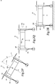
- cargo 26, nose cone 30a and afterbody 30b may be removed from airframe 12, as best seen in figures 5A-5B , upon delivery of cargo 26 resulting in a minimal drag flight configuration of aircraft 10, as best seen in figures 1G-1H .
- Aircraft 10 and cargo enclosure 30 preferably have remote release capabilities of cargo 26.
- this feature allows airframe 12 to deliver cargo 26 to a desired location following transportation without the requirement for landing.
- afterbody 30b preferably includes a pair of trailing edge members depicted as rotatable doors that operate in a clamshell manner relative to pylons 18, 20 responsive to instructions received from flight control system 22.
- flight control system 22 has caused the doors of afterbody 30b to open such that cargo 26 can be released from aircraft 10 via airdrop.
- cargo 26 has a parachute 36 attached thereto to aid in controlling the speed at which cargo 26 descends to the ground.
- cargo 26 may be airdropped from aircraft 10 without the aid of a parachute.
- the delivery or pickup of cargo 26 may be accomplished using a cargo hook module including a cargo hoisting device 38 disposed within nose cone 30a that is operable to raise and/or lower cargo 26 while aircraft 10 remains in a stable hover, as indicated by arrow 40 in figure 6B .
- Cargo hoisting device 38 may include a retractable hoisting cable 42 that is supported by a cargo hook winch system 44. It should be noted that these remote release capabilities allow aircraft 10 to jettison cargo 26 during flight, for example, in the event of an emergency situation such as a propulsion assembly or other system of aircraft 10 becoming compromised.
- flight control system 22 commences operations providing flight commands to the various components of aircraft 10.
- Flight control system 22 may be operating responsive to autonomous flight control, remote flight control or a combination thereof. For example, it may be desirable to utilize remote flight control during certain maneuvers such as takeoff and landing but rely on autonomous flight control during hover, high speed forward flight and/or transitions between wing-borne flight and thrust-borne flight.
- aircraft 10 has performed a vertical takeoff and is engaged in thrust-borne lift in the VTOL orientation of aircraft 10.
- rotor assemblies 24i of propulsion assemblies 24 are each rotating in the same horizontal plane.
- longitudinal axis 10a and lateral axis 10b (denoted as the target) are both in a horizontal plane H that is normal to the local vertical in the earth's reference frame, aircraft 10 has a level flight attitude.
- wing 14 is forward of cargo enclosure 30 and wing 16 is aft of cargo enclosure 30.
- flight control system 22 independently controls and operates each propulsion assembly 24 including independently controlling speed and thrust vector.
- flight control system 22 may utilize differential speed control and/or differential or collective thrust vectoring of propulsion assemblies 24 to provide hover stability for aircraft 10 and to provide pitch, roll, yaw and translation authority for aircraft 10.
- aircraft 10 may begin the transition from thrust-borne lift to wing-borne lift.
- aircraft 10 is operable to pitch down from the VTOL orientation toward the biplane orientation to enable high speed and/or long range forward flight.
- longitudinal axis 10a extends out of the horizontal plane H such that aircraft 10 has an inclined flight attitude of about thirty degrees pitch down.
- longitudinal axis 10a extends out of the horizontal plane H such that aircraft 10 has an inclined flight attitude of about sixty degrees pitch down.
- Flight control system 22 may achieve this operation through speed control of some or all of propulsion assemblies 24, thrust vectoring of some or all of propulsion assemblies 24 or any combination thereof.
- rotor assemblies 24i of propulsion assemblies 24 are each rotating in the same vertical plane.
- wing 14 is below cargo enclosure 30 and wing 16 is above cargo enclosure 30.
- longitudinal axis 10a has been reset to be in the horizontal plane H, which also includes lateral axis 10b, such that aircraft 10 has a level flight attitude in the biplane orientation.
- H horizontal plane
- lateral axis 10b the operating speed of some or all of the propulsion assemblies 24 may be reduced. In certain embodiments, some of the propulsion assemblies of aircraft 10 could be shut down during forward flight.
- aircraft 10 In the biplane orientation, the independent control provided by flight control system 22 over each propulsion assembly 24 provides pitch, roll and yaw authority using collective or differential thrust vectoring, differential speed control or any combination thereof. As aircraft 10 approaches its destination, aircraft 10 may begin its transition from wing-borne lift to thrust-borne lift. As best seen from the progression of figures 2E-2H , aircraft 10 is operable to pitch up from the biplane orientation to the VTOL orientation to enable, for example, a vertical landing operation. As seen in figure 2F , longitudinal axis 10a extends out of the horizontal plane H such that aircraft 10 has an inclined flight attitude of about thirty degrees pitch up.
- longitudinal axis 10a extends out of the horizontal plane H such that aircraft 10 has an inclined flight attitude of about sixty degrees pitch up.
- Flight control system 22 may achieve this operation through speed control of some or all of propulsion assemblies 24, thrust vectoring of some or all of propulsion assemblies 24 or any combination thereof.
- aircraft 10 has completed the transition from the biplane orientation to the VTOL orientation and, by convention, longitudinal axis 10a has been reset to be in the horizontal plane H which also includes lateral axis 10b such that aircraft 10 has a level flight attitude in the VTOL orientation.
- aircraft 10 may commence its vertical descent to a surface.
- aircraft 10 has landing in a tailsitter orientation at the destination location.
- Cargo 26 may now be removed from cargo enclosure 30 through an automated or manual process.
- aircraft 10 is now in its minimal drag flight configuration in which air is able to pass through the central region of airframe 12 between wings 14, 16 and pylons 18, 20.
- the minimal drag flight configuration of aircraft 10 is a low weight and high efficiency configuration that enables reduced fuel consumption when aircraft 10 is not carrying cargo 26.
- aircraft 10 is in a tailsitter position on the ground with cargo enclosure 30 removed from airframe 12.
- flight control system 22 commences operations providing flight commands to the various components of aircraft 10. Flight control system 22 may be operating responsive to autonomous flight control, remote flight control or a combination thereof.
- aircraft 10 has performed a vertical takeoff and is engaged in thrust-borne lift in the VTOL orientation of aircraft 10.
- rotor assemblies 24i of propulsion assemblies 24 are each rotating in the same horizontal plane.
- longitudinal axis 10a and lateral axis 10b are both in horizontal plane H, aircraft 10 has a level flight attitude.
- flight control system 22 may utilize differential speed control and/or differential or collective thrust vectoring of propulsion assemblies 24 to provide hover stability for aircraft 10 and to provide pitch, roll, yaw and translation authority for aircraft 10.
- aircraft 10 may begin the transition from thrust-borne lift to wing-borne lift.
- aircraft 10 is operable to pitch down from the VTOL orientation toward the biplane orientation to enable high speed and/or long range forward flight.
- longitudinal axis 10a extends out of the horizontal plane H such that aircraft 10 has an inclined flight attitude of about thirty degrees pitch down.
- longitudinal axis 10a extends out of the horizontal plane H such that aircraft 10 has an inclined flight attitude of about sixty degrees pitch down.
- Flight control system 22 may achieve this operation through speed control of some or all of propulsion assemblies 24, thrust vectoring of some or all of propulsion assemblies 24 or any combination thereof.
- rotor assemblies 24i of propulsion assemblies 24 are each rotating in the same vertical plane.
- longitudinal axis 10a has been reset to be in the horizontal plane H, which also includes lateral axis 10b, such that aircraft 10 has a level flight attitude in the biplane orientation.
- the independent control provided by flight control system 22 over each propulsion assembly 24 provides pitch, roll and yaw authority using collective or differential thrust vectoring, differential speed control or any combination thereof.
- aircraft 10 may begin its transition from wing-borne lift to thrust-borne lift.
- aircraft 10 is operable to pitch up from the biplane orientation to the VTOL orientation to enable, for example, a vertical landing operation.
- longitudinal axis 10a extends out of the horizontal plane H such that aircraft 10 has an inclined flight attitude of about thirty degrees pitch up.
- longitudinal axis 10a extends out of the horizontal plane H such that aircraft 10 has an inclined flight attitude of about sixty degrees pitch up.
- Flight control system 22 may achieve this operation through speed control of some or all of propulsion assemblies 24, thrust vectoring of some or all of propulsion assemblies 24 or any combination thereof.
- aircraft 10 has completed the transition from the biplane orientation to the VTOL orientation and, by convention, longitudinal axis 10a has been reset to be in the horizontal plane H which also includes lateral axis 10b such that aircraft 10 has a level flight attitude in the VTOL orientation.
- aircraft 10 may commence its vertical descent to a surface.
- aircraft 10 has landing in a tailsitter orientation at the destination location.
- FIG. 3 a block diagram illustrates one implementation of a thrust array and flight control system for an aircraft 100 that is representative of aircraft 10 discussed herein.
- aircraft 100 includes four propulsion assemblies 102a, 102b, 102c, 102d that form a two-dimensional thrust array of thrust vectoring propulsion assemblies.
- Propulsion assembly 102a includes an electronics node 104a depicted as including controllers, sensors and one or more batteries.
- Propulsion assembly 102a also includes a propulsion system 106a described herein as including an electric motor and a rotor assembly.
- propulsion assembly 102a includes a two-axis gimbal 108a operated by one or more actuators 110a.
- propulsion assembly 102a may include a single-axis gimbal or other mechanism for thrust vectoring.
- propulsion assembly 102a may be a non thrust vectoring propulsion assembly.
- Propulsion assembly 102b includes an electronics node 104b depicted as including controllers, sensors and one or more batteries. Propulsion assembly 102b also includes a propulsion system 106b described herein as including an electric motor and a rotor assembly. In the illustrated embodiment, propulsion assembly 102b includes a two-axis gimbal 108b operated by one or more actuators 110b. Propulsion assembly 102c includes an electronics node 104c depicted as including controllers, sensors and one or more batteries. Propulsion assembly 102c also includes a propulsion system 106c described herein as including an electric motor and a rotor assembly. In the illustrated embodiment, propulsion assembly 102c includes a two-axis gimbal 108c operated by one or more actuators 110c.
- Propulsion assembly 102d includes an electronics node 104d depicted as including controllers, sensors and one or more batteries. Propulsion assembly 102d also includes a propulsion system 106d described herein as including an electric motor and a rotor assembly. In the illustrated embodiment, propulsion assembly 102d includes a two-axis gimbal 108d operated by one or more actuators 110d.
- a flight control system 112 is operably associated with each of propulsion assemblies 102a, 102b, 102c, 102d and is communicably linked to the electronic nodes 104a, 104b, 104c, 104d thereof by a communications network depicted as arrows 114a, 114b, 114c, 114d between flight control system 112 and propulsion assemblies 102a, 102b, 102c, 102d.
- Flight control system 112 receives sensor data from and sends commands to propulsion assemblies 102a, 102b, 102c, 102d to enable flight control system 112 to independently control each of propulsion assemblies 102a, 102b, 102c, 102d as discussed herein.
- system 120 includes two primary computer based subsystems; namely, an airframe system 122 and a remote system 124.
- remote system 124 includes a programming application 126 and a remote control application 128.
- Programming application 126 enables a user to provide a flight plan and mission information to aircraft 100 such that flight control system 112 may engage in autonomous control over aircraft 100.
- programming application 126 may communicate with flight control system 112 over a wired or wireless communication channel 130 to provide a flight plan including, for example, a staring point, a trail of waypoints and an ending point such that flight control system 112 may use waypoint navigation during the mission.
- programming application 126 may provide one or more tasks to flight control system 112 for aircraft 100 to accomplish during the mission.
- aircraft 100 may operate autonomously responsive to commands generated by flight control system 112.
- Flight control system 112 preferably includes a non-transitory computer readable storage medium including a set of computer instructions executable by a processor.
- Flight control system 112 may be a triply redundant system implemented on one or more general-purpose computers, special purpose computers or other machines with memory and processing capability.
- flight control system 112 may include one or more memory storage modules including, but is not limited to, internal storage memory such as random access memory, non-volatile memory such as read only memory, removable memory such as magnetic storage memory, optical storage, solid-state storage memory or other suitable memory storage entity.
- Flight control system 112 may be a microprocessor-based system operable to execute program code in the form of machine-executable instructions.
- flight control system 112 may be selectively connectable to other computer systems via a proprietary encrypted network, a public encrypted network, the Internet or other suitable communication network that may include both wired and wireless connections.
- flight control system 112 includes a command module 132 and a monitoring module 134. It is to be understood by those skilled in the art that these and other modules executed by flight control system 112 may be implemented in a variety of forms including hardware, software, firmware, special purpose processors and combinations thereof. Flight control system 112 receives input from a variety of sources including internal sources such as sensors 136, controllers 138 and propulsion assemblies 102a, 102b, 102c, 102d and external sources such as remote system 124 as well as global positioning system satellites or other location positioning systems and the like. For example, as discussed herein, flight control system 112 may receive a flight plan for a mission from remote system 124. Thereafter, flight control system 112 may be operable to autonomously control all aspects of flight of an aircraft of the present disclosure.
- sources including internal sources such as sensors 136, controllers 138 and propulsion assemblies 102a, 102b, 102c, 102d and external sources such as remote system 124 as well as global positioning system satellites or other location positioning systems and
- command module 132 provides commands to controllers 138. These commands enable independent operation of each propulsion assembly 102a, 102b, 102c, 102d including rotor speed, thrust vector and the like.
- Flight control system 112 receives feedback from controllers 138 and each propulsion assembly 102a, 102b, 102c, 102d. This feedback is processes by monitoring module 134 that can supply correction data and other information to command module 132 and/or controllers 138.
- Sensors 136 such as positioning sensors, attitude sensors, speed sensors, environmental sensors, fuel sensors, temperature sensors, location sensors and the like also provide information to flight control system 112 to further enhance autonomous control capabilities.
- Remote system 124 may include one or computing systems that may be implemented on general-purpose computers, special purpose computers or other machines with memory and processing capability.
- the computing systems may include one or more memory storage modules including, but is not limited to, internal storage memory such as random access memory, non-volatile memory such as read only memory, removable memory such as magnetic storage memory, optical storage memory, solid-state storage memory or other suitable memory storage entity.
- the computing systems may be microprocessor-based systems operable to execute program code in the form of machine-executable instructions.
- the computing systems may be connected to other computer systems via a proprietary encrypted network, a public encrypted network, the Internet or other suitable communication network that may include both wired and wireless connections.
- the communication network may be a local area network, a wide area network, the Internet, or any other type of network that couples a plurality of computers to enable various modes of communication via network messages using as suitable communication techniques, such as transmission control protocol/internet protocol, file transfer protocol, hypertext transfer protocol, internet protocol security protocol, point-to-point tunneling protocol, secure sockets layer protocol or other suitable protocol.
- Remote system 124 communicates with flight control system 112 via a communication link 130 that may include both wired and wireless connections.
- remote system 124 is configured to display information relating to one or more aircraft of the present disclosure on one or more flight data display devices 140.
- Display devices 140 may be configured in any suitable form, including, for example, liquid crystal displays, light emitting diode displays or any suitable type of display.
- Remote system 124 may also include audio output and input devices such as a microphone, speakers and/or an audio port allowing an operator to communicate with other operators or a base station.
- the display device 140 may also serve as a remote input device 142 if a touch screen display implementation is used, however, other remote input devices, such as a keyboard or joystick, may alternatively be used to allow an operator to provide control commands to an aircraft being operated responsive to remote control.
Landscapes
- Engineering & Computer Science (AREA)
- Aviation & Aerospace Engineering (AREA)
- Mechanical Engineering (AREA)
- Chemical & Material Sciences (AREA)
- Combustion & Propulsion (AREA)
- Remote Sensing (AREA)
- Control Of Position, Course, Altitude, Or Attitude Of Moving Bodies (AREA)
Abstract
Description
- The present application is a continuation-in-part of
co-pending application number 16/246,474 filed January 12, 2019 15/200,197 filed July 1, 2016 10,220,944 - The present disclosure relates, in general, to aircraft operable to transition between thrust-borne lift in a VTOL orientation and wing-borne lift in a biplane orientation and, in particular, to logistics support aircraft having a cargo delivery flight configuration and a minimal drag flight configuration.
- Fixed-wing aircraft, such as airplanes, are capable of flight using wings that generate lift responsive to the forward airspeed of the aircraft, which is generated by thrust from one or more jet engines or propellers. The wings generally have an airfoil cross section that deflects air downward as the aircraft moves forward, generating the lift force to support the airplane in flight. Fixed-wing aircraft, however, typically require a runway that is hundreds or thousands of feet long for takeoff and landing. Unlike fixed-wing aircraft, vertical takeoff and landing (VTOL) aircraft do not require runways. Instead, VTOL aircraft are capable of taking off, hovering and landing vertically. One example of VTOL aircraft is a helicopter which is a rotorcraft having one or more rotors that provide lift and thrust to the aircraft. The rotors not only enable hovering and vertical takeoff and landing, but also enable, forward, backward and lateral flight. These attributes make helicopters highly versatile for use in congested, isolated or remote areas where fixed-wing aircraft may be unable to takeoff and land. Helicopters, however, typically lack the forward airspeed of fixed-wing aircraft.
- A tiltrotor aircraft is another example of a VTOL aircraft. Tiltrotor aircraft generate lift and propulsion using proprotors that are typically coupled to nacelles mounted near the ends of a fixed wing. The nacelles rotate relative to the fixed wing such that the proprotors have a generally horizontal plane of rotation for vertical takeoff, hovering and landing and a generally vertical plane of rotation for forward flight, wherein the fixed wing provides lift and the proprotors provide forward thrust. In this manner, tiltrotor aircraft combine the vertical lift capability of a helicopter with the speed and range of fixed-wing aircraft. Tiltrotor aircraft, however, typically suffer from downwash inefficiencies during vertical takeoff and landing due to interference caused by the fixed wing. A further example of a VTOL aircraft is a tiltwing aircraft that features a rotatable wing that is generally horizontal for forward flight and rotates to a generally vertical orientation for vertical takeoff and landing. Propellers are coupled to the rotating wing to provide the required vertical thrust for takeoff and landing and the required forward thrust to generate lift from the wing during forward flight. The tiltwing design enables the slipstream from the propellers to strike the wing on its smallest dimension, thus improving vertical thrust efficiency as compared to tiltrotor aircraft. Tiltwing aircraft, however, are more difficult to control during hover as the vertically tilted wing provides a large surface area for crosswinds typically requiring tiltwing aircraft to have either cyclic rotor control or an additional thrust station to generate a moment.
- In a first aspect, the present disclosure is directed to an aircraft operable to transition between thrust-borne lift in a VTOL orientation and wing-borne lift in a biplane orientation. The aircraft includes an airframe having first and second wings with first and second pylons extending therebetween forming a central region. A two-dimensional distributed thrust array is attached to the airframe. The thrust array includes a plurality of propulsion assemblies coupled to the first wing and a plurality of propulsion assemblies coupled to the second wing. A flight control system is coupled to the airframe and is operable to independently control each of the propulsion assemblies. A nose cone is selectively coupled to the airframe such that the nose cone extends between the first and second wings and between first and second pylons. An afterbody is selectively coupled to the airframe such that the afterbody extends between the first and second wings and between first and second pylons. In a cargo delivery flight configuration, the nose cone and the afterbody are coupled to the airframe to form a cargo enclosure with an aerodynamic outer shape. In a minimal drag flight configuration, the nose cone and the afterbody are not coupled to the airframe such that air passes through the central region during flight.
- In certain embodiments, in the biplane orientation, the first wing may be an upper wing having a dihedral configuration and the second wing may be a lower wing having an anhedral configuration. In some embodiments, the central region may form a rectangle having a major dimension extending between the first and second wings and a minor dimension extending between first and second pylons, wherein the major dimension is greater than the minor dimension. In such embodiments, the major dimension may be between about two times and about four times greater than the minor dimension, the major dimension may be between about two times and about three times greater than the minor dimension or the major dimension may be about two and half times greater than the minor dimension. In certain embodiments, each of the propulsion assemblies may be outboard of the central region. In some embodiments, each of the propulsion assemblies may include a variable speed electric motor and a rotor assembly. In certain embodiments, each of the propulsion assemblies may be a thrust vectoring propulsion assembly such as a longitudinal thrust vectoring propulsion assembly or an omnidirectional thrust vectoring propulsion assembly.
- In some embodiments, each of the propulsion assemblies may include a tail assembly with at least one aerosurface. In certain embodiments, two propulsion assemblies may be coupled to the first wing and two propulsion assemblies may be coupled to the second wing. In some embodiments, the nose cone may include a leading edge fairing that is slidably receivable on the airframe. In certain embodiments, the afterbody may include a trailing edge fairing that is slidably receivable on the airframe. In such embodiments, the trailing edge fairing may include first and second trailing edge members that are rotatable relative to the first and second pylons, respectively, such that the first and second trailing edge members have open and closed positions.
- In a second aspect, the present disclosure is directed to a method of operating an aircraft. The method includes providing an airframe having first and second wings with first and second pylons extending therebetween forming a central region, a plurality of propulsion assemblies coupled to the first wing, a plurality of propulsion assemblies coupled to the second wing and a flight control system operable to independently control each of the propulsion assemblies; forming a cargo enclosure having an aerodynamic outer shape by attaching a nose cone to the airframe such that the nose cone extends between the first and second wings and between first and second pylons and by attaching an afterbody to the airframe such that the afterbody extends between the first and second wings and between first and second pylons; disposing cargo within the cargo enclosure; transporting the cargo by air from a first location to a second location including transitioning the aircraft between thrust-borne lift in a VTOL orientation and wing-borne lift in a biplane orientation; removing the cargo from the cargo enclosure at the second location; detaching the nose cone and the afterbody from the airframe forming a minimal drag flight configuration in which air passes through the central region during flight; and returning the aircraft by air from the second location to the first location in the minimal drag flight configuration including transitioning the aircraft between thrust-borne lift in the VTOL orientation and wing-borne lift in the biplane orientation.
- The method may also include transitioning the aircraft between the VTOL orientation wherein the first wing is forward of the cargo enclosure and the second wing is aft of the cargo enclosure and the biplane orientation wherein the first wing is below the cargo enclosure and the second wing is above the cargo enclosure; operating the aircraft responsive to autonomous flight control; operating the aircraft responsive to remote flight control; operating the aircraft responsive to a combination of remote flight control and autonomous flight control and/or attaching the nose cone to the airframe by slidably receiving a leading edge fairing on the airframe; attaching the afterbody to the airframe by slidably receiving a trailing edge fairing on the airframe; detaching the nose cone from the airframe by slidably removing the leading edge fairing from the airframe; and detaching the afterbody from the airframe by slidably removing the trailing edge fairing from the airframe.
- For a more complete understanding of the features and advantages of the present disclosure, reference is now made to the detailed description along with the accompanying figures in which corresponding numerals in the different figures refer to corresponding parts and in which:
-
Figures 1A-1H are schematic illustrations of an aircraft operable to transition between thrust-borne lift in a VTOL orientation and wing-borne lift in a biplane orientation in accordance with embodiments of the present disclosure; -
Figures 2A-2R are schematic illustrations of the aircraft offigures 1 in a sequential flight operating scenario in accordance with embodiments of the present disclosure; -
Figure 3 is a block diagram of one implementation of a thrust array and a flight control system for an aircraft in accordance with embodiments of the present disclosure; -
Figure 4 is a block diagram of autonomous and remote control systems for an aircraft in accordance with embodiments of the present disclosure; -
Figures 5A-5B are schematic illustrations of a coupling implementation of a cargo enclosure for an aircraft in accordance with embodiments of the present disclosure; and -
Figures 6A-6B are schematic illustrations of cargo delivery implementations enabled by an aircraft in accordance with embodiments of the present disclosure. - While the making and using of various embodiments of the present disclosure are discussed in detail below, it should be appreciated that the present disclosure provides many applicable inventive concepts, which can be embodied in a wide variety of specific contexts. The specific embodiments discussed herein are merely illustrative and do not delimit the scope of the present disclosure. In the interest of clarity, not all features of an actual implementation may be described in the present disclosure. It will of course be appreciated that in the development of any such actual embodiment, numerous implementation-specific decisions must be made to achieve the developer's specific goals, such as compliance with system-related and business-related constraints, which will vary from one implementation to another. Moreover, it will be appreciated that such a development effort might be complex and time-consuming but would be a routine undertaking for those of ordinary skill in the art having the benefit of this disclosure.
- In the specification, reference may be made to the spatial relationships between various components and to the spatial orientation of various aspects of components as the devices are depicted in the attached drawings. However, as will be recognized by those skilled in the art after a complete reading of the present disclosure, the devices, members, apparatuses, and the like described herein may be positioned in any desired orientation. Thus, the use of terms such as "above," "below," "upper," "lower" or other like terms to describe a spatial relationship between various components or to describe the spatial orientation of aspects of such components should be understood to describe a relative relationship between the components or a spatial orientation of aspects of such components, respectively, as the device described herein may be oriented in any desired direction. As used herein, the term "coupled" may include direct or indirect coupling by any means, including moving and/or non-moving mechanical connections.
- Referring to
figures 1A-1H in the drawings, various views of anaircraft 10 operable to transition between thrust-borne lift in a VTOL orientation and wing-borne lift in a biplane orientation are depicted.Figures 1A ,1C ,1E and1G depictaircraft 10 in the VTOL orientation wherein the propulsion assemblies provide thrust-borne lift.Figures 1B ,1D ,1F and1H depictaircraft 10 in the biplane orientation wherein the propulsion assemblies provide forward thrust with the forward airspeed ofaircraft 10 providing wing-bornelift enabling aircraft 10 to have a high speed and/or high endurance forward flight mode.Aircraft 10 has alongitudinal axis 10a that may also be referred to as the roll axis, alateral axis 10b that may also be referred to as the pitch axis and avertical axis 10c that may also be referred to as the yaw axis, as best seen in figures IE and IF. Whenlongitudinal axis 10a andlateral axis 10b are both in a horizontal plane and normal to the local vertical in the earth's reference frame,aircraft 10 has a level flight attitude. - In the illustrated embodiment,
aircraft 10 includes anairframe 12 includingwings aircraft 10.Wings wings figure 1B , in the biplane orientation ofaircraft 10,wing 16 is an upper wing having a dihedral configuration andwing 14 is a lower wing having an anhedral configuration. In other embodiments,wings wings pylons Pylons figures 1G-1H ,wings pylons wings pylons -
Wings pylons figures 1C and 1D , pylon 20 houses theflight control system 22 ofaircraft 10.Flight control system 22 is preferably a redundant digital flight control system including multiple independent flight control computers. For example, the use of a triply redundantflight control system 22 improves the overall safety and reliability ofaircraft 10 in the event of a failure inflight control system 22.Flight control system 22 preferably includes non-transitory computer readable storage media including a set of computer instructions executable by one or more processors for controlling the operation ofaircraft 10.Flight control system 22 may be implemented on one or more general-purpose computers, special purpose computers or other machines with memory and processing capability. For example,flight control system 22 may include one or more memory storage modules including, but is not limited to, internal storage memory such as random access memory, non-volatile memory such as read only memory, removable memory such as magnetic storage memory, optical storage, solid-state storage memory or other suitable memory storage entity.Flight control system 22 may be a microprocessor-based system operable to execute program code in the form of machine-executable instructions. In addition,flight control system 22 may be selectively connectable to other computer systems via a proprietary encrypted network, a public encrypted network, the Internet or other suitable communication network that may include both wired and wireless connections. -
Wings pylons more batteries 22a inpylon 20, as best seen infigures 1C and 1D .Batteries 22a supply electrical power toflight control system 22. In some embodiments,batteries 22a may be used to supply electrical power for the distributed thrust array ofaircraft 10.Wings pylons flight control system 22 to communicate with the distributed thrust array ofaircraft 10. In the illustrated embodiment,aircraft 10 has a two-dimensional distributed thrust array that is coupled toairframe 12. As used herein, the term "two-dimensional thrust array" refers to a plurality of thrust generating elements that occupy a two-dimensional space in the form of a plane. A minimum of three thrust generating elements is required to form a "two-dimensional thrust array." A single aircraft may have more than one "two-dimensional thrust array" if multiple groups of at least three thrust generating elements each occupy separate two-dimensional spaces thus forming separate planes. As used herein, the term "distributed thrust array" refers to the use of multiple thrust generating elements each producing a portion of the total thrust output. The use of a "distributed thrust array" provides redundancy to the thrust generation capabilities of the aircraft including fault tolerance in the event of the loss of one of the thrust generating elements. A "distributed thrust array" can be used in conjunction with a "distributed power system" in which power to each of the thrust generating elements is supplied by a local power system instead of a centralized power source. For example, in a "distributed thrust array" having a plurality of propulsion assemblies acting as the thrust generating elements, a "distributed power system" may include individual battery elements housed within the nacelle of each propulsion assembly. - The two-dimensional distributed thrust array of
aircraft 10 includes a plurality of propulsion assemblies, individually and collectively denoted as 24. In the illustrated embodiment, twopropulsion assemblies 24 are coupled towing 14 and twopropulsion assemblies 24 are coupled towing 16 such that eachpropulsion assembly 24 is outboard of the central region ofairframe 12. In other embodiments,aircraft 10 could have other numbers of propulsion assemblies both greater than or less than four in other configurations. In the illustrated embodiment,propulsion assemblies 24 are variable speed propulsion assemblies having fixed pitch rotor blades and thrust vectoring capability. Depending upon the implementation,propulsion assemblies 24 may have longitudinal thrust vectoring capability, lateral thrust vectoring capability or omnidirectional thrust vectoring capability. In other embodiments,propulsion assemblies 24 may be single speed propulsion assemblies, may have variable pitch rotor blades and/or may be non thrust vectoring propulsion assemblies. - In the illustrated embodiment,
propulsion assemblies 24 are coupled to the outboard ends ofwings propulsion assemblies 24 could be coupled towings Propulsion assemblies 24 may be independently attachable to and detachable fromairframe 12 and may be standardized and/or interchangeable units and preferably line replaceable units providing easy installation and removal fromairframe 12. The use of line replaceable propulsion units is beneficial in maintenance situations if a fault is discovered with one of the propulsion assemblies. In this case, thefaulty propulsion assembly 24 can be decoupled fromairframe 12 by simple operations and anotherpropulsion assembly 24 can then be attached toairframe 12. In other embodiments,propulsion assemblies 24 may be permanently coupled towings - As best seen in
figure 1A , eachpropulsion assembly 24 includes anacelle 24a that houses components including abattery 24b, anelectronic speed controller 24c, agimbal actuator 24d, anelectronics node 24e, sensors and other desired electronic equipment.Nacelle 24a also supports apropulsion system 24f including agimbal 24g, a variable speedelectric motor 24h and arotor assembly 24i. Extending from a lower end ofnacelle 24a is atail assembly 24j that includesaerosurfaces 24k. As the power for eachpropulsion assembly 24 is provided bybatteries 24b housed within therespective nacelle 24a,aircraft 10 has a distributed power system for the distributed thrust array. Alternatively or additionally, electrical power may be supplied to theelectric motors 24h and/or thebatteries 24b disposed with thenacelles 24a frombatteries 22a carried byairframe 12 via the communications network. In other embodiments, power for the propulsion assemblies ofaircraft 10 may be provided by one or more internal combustion engines, electric generators and/or hydraulic motors. In the illustrated embodiment, aerosurfaces 24k ofpropulsion assemblies 24 are stationary and are parallel to the respective wing to which the nacelle is attached to primarily serve as horizontal stabilizers. In other embodiments,aerosurfaces 24k may additionally or alternatively include vertical stabilizers. In still other embodiments,aerosurfaces 24k may be active aerosurfaces that serve as elevators to control the pitch or angle of attack ofwings aircraft 10 in the biplane orientation ofaircraft 10.Aerosurfaces 24 also serve to enhance hover stability in the VTOL orientation ofaircraft 10. -
Flight control system 22 communicates via the wired communications network ofairframe 12 with theelectronics nodes 24e of thepropulsion assemblies 24.Flight control system 22 receives sensor data from and sends flight command information to theelectronics nodes 24e such that eachpropulsion assembly 24 may be individually and independently controlled and operated. For example,flight control system 22 is operable to individually and independently control the speed and the thrust vector of eachpropulsion assembly 24.Flight control system 22 may autonomously control some or all aspects of flight operation foraircraft 10.Flight control system 22 is also operable to communicate with remote systems, such as a ground station via a wireless communications protocol. The remote system may be operable to receive flight data from and provide commands toflight control system 22 to enable remote flight control over some or all aspects of flight operation foraircraft 10. The autonomous and/or remote operation ofaircraft 10 enablesaircraft 10 to perform unmanned logistics operations for both military and commercial applications. - Each
propulsion assembly 24 includes arotor assembly 24i that is coupled to an output drive of a respectiveelectrical motor 24h that rotates therotor assembly 24i in a rotational plane to generate thrust foraircraft 10. In the illustrated embodiment,rotor assemblies 24i each include four rotor blades having a fixed pitch. In other embodiments, the rotor assemblies could have other numbers of rotor blades including rotor assemblies having less than or more than four rotor blades. Alternatively or additionally, the rotor assemblies could have variable pitch rotor blades with collective and/or cyclic pitch control. Eachelectrical motor 24h is paired with arotor assembly 24i to form apropulsion system 24f. In the illustrated embodiment, eachpropulsion system 24f has a two-axis tilting degree of freedom relative tonacelle 24a provided bygimbal 24g such thatpropulsion assemblies 24 are omnidirectional thrust vectoring propulsion assemblies. In the illustrated embodiment, the maximum angle of the thrust vector may preferably be between about 10 degrees and about 30 degrees, may more preferably be between about 15 degrees and about 25 degrees and may most preferably be about 20 degrees. Notably, using a 20-degree thrust vector yields a lateral component of thrust that is about 34 percent of total thrust. In other embodiments, the propulsion systems may have a single-axis tilting degree of freedom in which case, the propulsion assemblies could act as longitudinal and/or lateral thrust vectoring propulsion assemblies. - In one non-limiting example,
aircraft 10 may operate as a logistics support aircraft. As best seen infigure 1A , cargo depicted as apackage 26 has been secured within acargo enclosure 30 ofaircraft 10.Cargo enclosure 30 has an aerodynamic outer shape and is selectively attachable to and detachable fromairframe 12. In the illustrated embodiment,cargo enclosure 30 is formed from a nose cone depicted as a leading edge fairing 30a and an afterbody depicted as a trailing edge fairing 30b.Nose cone 30a may be securably coupled to the top ofairframe 12 whenaircraft 10 is resting in the tailsitter position, such thatnose cone 30a extends betweenwings pylons afterbody 30b may be securably coupled to the bottom ofairframe 12 whenaircraft 10 is resting in the tailsitter position, such thatafterbody 30b extends betweenwings pylons figure 5A ,nose cone 30a may be slidably received byairframe 12 on a rail system or other suitable connection, as indicates by thearrow 32. Oncenose cone 30a is fully positioned onairframe 12,nose cone 30a may be locked thereto to prevent relative movement. Likewise, as best seen infigure 5B ,afterbody 30b may be slidably received byairframe 12 on a rail system or other suitable connection, as indicates by thearrow 34. Onceafterbody 30b is fully positioned onairframe 12,afterbody 30b may be locked thereto to prevent relative movement. In other embodiments,nose cone 30a and/orafterbody 30b may be securably coupled toairframe 12 by bolting, snapping, clipping, pinning or other suitable technique. - In the illustrated implementation,
cargo 26 is depicted as a single package carried withincargo enclosure 30. In other implementation,cargo 26 may be composed of any number of packages or other items that can be carried withincargo enclosure 30. Preferably,cargo 26 is fixably coupled withincargo enclosure 30 by suitable means to prevent relative movement therebetween, thus protectingcargo 26 from damage and maintaining a stable center of mass foraircraft 10. In addition,cargo 26 may be insertable into and removable fromcargo enclosure 30 to enable sequential cargo pickup, transportation and delivery operations to and from multiple locations. Alternatively or additionally,cargo 26,nose cone 30a andafterbody 30b may be removed fromairframe 12, as best seen infigures 5A-5B , upon delivery ofcargo 26 resulting in a minimal drag flight configuration ofaircraft 10, as best seen infigures 1G-1H . -
Aircraft 10 andcargo enclosure 30 preferably have remote release capabilities ofcargo 26. For example, this feature allowsairframe 12 to delivercargo 26 to a desired location following transportation without the requirement for landing. In this case,afterbody 30b preferably includes a pair of trailing edge members depicted as rotatable doors that operate in a clamshell manner relative topylons flight control system 22. For example, as best seen infigure 6A , during a package delivery mission and upon reaching the desired location,flight control system 22 has caused the doors ofafterbody 30b to open such thatcargo 26 can be released fromaircraft 10 via airdrop. In the illustrated embodiment,cargo 26 has aparachute 36 attached thereto to aid in controlling the speed at whichcargo 26 descends to the ground. In other implementations,cargo 26 may be airdropped fromaircraft 10 without the aid of a parachute. Alternatively, the delivery or pickup ofcargo 26 may be accomplished using a cargo hook module including acargo hoisting device 38 disposed withinnose cone 30a that is operable to raise and/orlower cargo 26 whileaircraft 10 remains in a stable hover, as indicated byarrow 40 infigure 6B .Cargo hoisting device 38 may include aretractable hoisting cable 42 that is supported by a cargohook winch system 44. It should be noted that these remote release capabilities allowaircraft 10 to jettisoncargo 26 during flight, for example, in the event of an emergency situation such as a propulsion assembly or other system ofaircraft 10 becoming compromised. - Referring additionally to
figures 2A-2R in the drawings, a sequential flight-operating scenario ofaircraft 10 is depicted. As best seen infigure 2A ,aircraft 10 is in a tailsitter position on the ground withcargo enclosure 30 attached toairframe 12 and withcargo 26 secured withincargo enclosure 30. Whenaircraft 10 is ready for a logistics support mission,flight control system 22 commences operations providing flight commands to the various components ofaircraft 10.Flight control system 22 may be operating responsive to autonomous flight control, remote flight control or a combination thereof. For example, it may be desirable to utilize remote flight control during certain maneuvers such as takeoff and landing but rely on autonomous flight control during hover, high speed forward flight and/or transitions between wing-borne flight and thrust-borne flight. - As best seen in
figure 2B ,aircraft 10 has performed a vertical takeoff and is engaged in thrust-borne lift in the VTOL orientation ofaircraft 10. As illustrated,rotor assemblies 24i ofpropulsion assemblies 24 are each rotating in the same horizontal plane. Aslongitudinal axis 10a andlateral axis 10b (denoted as the target) are both in a horizontal plane H that is normal to the local vertical in the earth's reference frame,aircraft 10 has a level flight attitude. In the VTOL orientation,wing 14 is forward ofcargo enclosure 30 andwing 16 is aft ofcargo enclosure 30. As discussed herein,flight control system 22 independently controls and operates eachpropulsion assembly 24 including independently controlling speed and thrust vector. During hover,flight control system 22 may utilize differential speed control and/or differential or collective thrust vectoring ofpropulsion assemblies 24 to provide hover stability foraircraft 10 and to provide pitch, roll, yaw and translation authority foraircraft 10. - After vertical ascent to the desired elevation,
aircraft 10 may begin the transition from thrust-borne lift to wing-borne lift. As best seen from the progression offigures 2B-2E ,aircraft 10 is operable to pitch down from the VTOL orientation toward the biplane orientation to enable high speed and/or long range forward flight. As seen infigure 2C ,longitudinal axis 10a extends out of the horizontal plane H such thataircraft 10 has an inclined flight attitude of about thirty degrees pitch down. As seen infigure 2D ,longitudinal axis 10a extends out of the horizontal plane H such thataircraft 10 has an inclined flight attitude of about sixty degrees pitch down.Flight control system 22 may achieve this operation through speed control of some or all ofpropulsion assemblies 24, thrust vectoring of some or all ofpropulsion assemblies 24 or any combination thereof. - As best seen in
figure 2E ,rotor assemblies 24i ofpropulsion assemblies 24 are each rotating in the same vertical plane. In the biplane orientation,wing 14 is belowcargo enclosure 30 andwing 16 is abovecargo enclosure 30. By convention,longitudinal axis 10a has been reset to be in the horizontal plane H, which also includeslateral axis 10b, such thataircraft 10 has a level flight attitude in the biplane orientation. As forward flight with wing-borne lift requires significantly less power then VTOL flight with thrust-borne lift, the operating speed of some or all of thepropulsion assemblies 24 may be reduced. In certain embodiments, some of the propulsion assemblies ofaircraft 10 could be shut down during forward flight. In the biplane orientation, the independent control provided byflight control system 22 over eachpropulsion assembly 24 provides pitch, roll and yaw authority using collective or differential thrust vectoring, differential speed control or any combination thereof. Asaircraft 10 approaches its destination,aircraft 10 may begin its transition from wing-borne lift to thrust-borne lift. As best seen from the progression offigures 2E-2H ,aircraft 10 is operable to pitch up from the biplane orientation to the VTOL orientation to enable, for example, a vertical landing operation. As seen infigure 2F ,longitudinal axis 10a extends out of the horizontal plane H such thataircraft 10 has an inclined flight attitude of about thirty degrees pitch up. As seen infigure 2G ,longitudinal axis 10a extends out of the horizontal plane H such thataircraft 10 has an inclined flight attitude of about sixty degrees pitch up.Flight control system 22 may achieve this operation through speed control of some or all ofpropulsion assemblies 24, thrust vectoring of some or all ofpropulsion assemblies 24 or any combination thereof. Infigure 2H ,aircraft 10 has completed the transition from the biplane orientation to the VTOL orientation and, by convention,longitudinal axis 10a has been reset to be in the horizontal plane H which also includeslateral axis 10b such thataircraft 10 has a level flight attitude in the VTOL orientation. Onceaircraft 10 has completed the transition to the VTOL orientation,aircraft 10 may commence its vertical descent to a surface. As best seen infigure 2I ,aircraft 10 has landing in a tailsitter orientation at the destination location.Cargo 26 may now be removed fromcargo enclosure 30 through an automated or manual process. - Continuing with the flight scenario illustrated in
figures 2J-2R ,cargo enclosure 30 has also been removed fromairframe 12 such thataircraft 10 is now in its minimal drag flight configuration in which air is able to pass through the central region ofairframe 12 betweenwings pylons aircraft 10 is a low weight and high efficiency configuration that enables reduced fuel consumption whenaircraft 10 is not carryingcargo 26. As best seen infigure 2J ,aircraft 10 is in a tailsitter position on the ground withcargo enclosure 30 removed fromairframe 12. Whenaircraft 10 is ready for the return mission,flight control system 22 commences operations providing flight commands to the various components ofaircraft 10.Flight control system 22 may be operating responsive to autonomous flight control, remote flight control or a combination thereof. - As best seen in
figure 2K ,aircraft 10 has performed a vertical takeoff and is engaged in thrust-borne lift in the VTOL orientation ofaircraft 10. As illustrated,rotor assemblies 24i ofpropulsion assemblies 24 are each rotating in the same horizontal plane. Aslongitudinal axis 10a andlateral axis 10b are both in horizontal plane H,aircraft 10 has a level flight attitude. During hover,flight control system 22 may utilize differential speed control and/or differential or collective thrust vectoring ofpropulsion assemblies 24 to provide hover stability foraircraft 10 and to provide pitch, roll, yaw and translation authority foraircraft 10. - After vertical ascent to the desired elevation,
aircraft 10 may begin the transition from thrust-borne lift to wing-borne lift. As best seen from the progression offigures 2K-2N ,aircraft 10 is operable to pitch down from the VTOL orientation toward the biplane orientation to enable high speed and/or long range forward flight. As seen infigure 2L ,longitudinal axis 10a extends out of the horizontal plane H such thataircraft 10 has an inclined flight attitude of about thirty degrees pitch down. As seen infigure 2M ,longitudinal axis 10a extends out of the horizontal plane H such thataircraft 10 has an inclined flight attitude of about sixty degrees pitch down.Flight control system 22 may achieve this operation through speed control of some or all ofpropulsion assemblies 24, thrust vectoring of some or all ofpropulsion assemblies 24 or any combination thereof. - As best seen in
figure 2N ,rotor assemblies 24i ofpropulsion assemblies 24 are each rotating in the same vertical plane. By convention,longitudinal axis 10a has been reset to be in the horizontal plane H, which also includeslateral axis 10b, such thataircraft 10 has a level flight attitude in the biplane orientation. As forward flight with wing-borne lift requires significantly less power then VTOL flight with thrust-borne lift, the operating speed of some or all of thepropulsion assemblies 24 may be reduced. In the biplane orientation, the independent control provided byflight control system 22 over eachpropulsion assembly 24 provides pitch, roll and yaw authority using collective or differential thrust vectoring, differential speed control or any combination thereof. Asaircraft 10 approaches its destination,aircraft 10 may begin its transition from wing-borne lift to thrust-borne lift. As best seen from the progression offigures 2N-2Q ,aircraft 10 is operable to pitch up from the biplane orientation to the VTOL orientation to enable, for example, a vertical landing operation. As seen infigure 2O ,longitudinal axis 10a extends out of the horizontal plane H such thataircraft 10 has an inclined flight attitude of about thirty degrees pitch up. As seen infigure 2P ,longitudinal axis 10a extends out of the horizontal plane H such thataircraft 10 has an inclined flight attitude of about sixty degrees pitch up.Flight control system 22 may achieve this operation through speed control of some or all ofpropulsion assemblies 24, thrust vectoring of some or all ofpropulsion assemblies 24 or any combination thereof. Infigure 2Q ,aircraft 10 has completed the transition from the biplane orientation to the VTOL orientation and, by convention,longitudinal axis 10a has been reset to be in the horizontal plane H which also includeslateral axis 10b such thataircraft 10 has a level flight attitude in the VTOL orientation. Onceaircraft 10 has completed the transition to the VTOL orientation,aircraft 10 may commence its vertical descent to a surface. As best seen infigure 2R ,aircraft 10 has landing in a tailsitter orientation at the destination location. - Referring next to
figure 3 , a block diagram illustrates one implementation of a thrust array and flight control system for anaircraft 100 that is representative ofaircraft 10 discussed herein. Specifically,aircraft 100 includes fourpropulsion assemblies Propulsion assembly 102a includes anelectronics node 104a depicted as including controllers, sensors and one or more batteries.Propulsion assembly 102a also includes apropulsion system 106a described herein as including an electric motor and a rotor assembly. In the illustrated embodiment,propulsion assembly 102a includes a two-axis gimbal 108a operated by one ormore actuators 110a. In other embodiments,propulsion assembly 102a may include a single-axis gimbal or other mechanism for thrust vectoring. In still other embodiments,propulsion assembly 102a may be a non thrust vectoring propulsion assembly. -
Propulsion assembly 102b includes anelectronics node 104b depicted as including controllers, sensors and one or more batteries.Propulsion assembly 102b also includes apropulsion system 106b described herein as including an electric motor and a rotor assembly. In the illustrated embodiment,propulsion assembly 102b includes a two-axis gimbal 108b operated by one ormore actuators 110b.Propulsion assembly 102c includes anelectronics node 104c depicted as including controllers, sensors and one or more batteries.Propulsion assembly 102c also includes apropulsion system 106c described herein as including an electric motor and a rotor assembly. In the illustrated embodiment,propulsion assembly 102c includes a two-axis gimbal 108c operated by one ormore actuators 110c.Propulsion assembly 102d includes anelectronics node 104d depicted as including controllers, sensors and one or more batteries.Propulsion assembly 102d also includes apropulsion system 106d described herein as including an electric motor and a rotor assembly. In the illustrated embodiment,propulsion assembly 102d includes a two-axis gimbal 108d operated by one ormore actuators 110d. - A
flight control system 112 is operably associated with each ofpropulsion assemblies electronic nodes arrows flight control system 112 andpropulsion assemblies Flight control system 112 receives sensor data from and sends commands topropulsion assemblies flight control system 112 to independently control each ofpropulsion assemblies - Referring additionally to
figure 4 in the drawings, a block diagram depicts acontrol system 120 operable for use withaircraft 100 oraircraft 10 of the present disclosure. In the illustrated embodiment,system 120 includes two primary computer based subsystems; namely, anairframe system 122 and aremote system 124. In some implementations,remote system 124 includes aprogramming application 126 and aremote control application 128.Programming application 126 enables a user to provide a flight plan and mission information toaircraft 100 such thatflight control system 112 may engage in autonomous control overaircraft 100. For example,programming application 126 may communicate withflight control system 112 over a wired orwireless communication channel 130 to provide a flight plan including, for example, a staring point, a trail of waypoints and an ending point such thatflight control system 112 may use waypoint navigation during the mission. In addition,programming application 126 may provide one or more tasks toflight control system 112 foraircraft 100 to accomplish during the mission. Following programming,aircraft 100 may operate autonomously responsive to commands generated byflight control system 112. -
Flight control system 112 preferably includes a non-transitory computer readable storage medium including a set of computer instructions executable by a processor.Flight control system 112 may be a triply redundant system implemented on one or more general-purpose computers, special purpose computers or other machines with memory and processing capability. For example,flight control system 112 may include one or more memory storage modules including, but is not limited to, internal storage memory such as random access memory, non-volatile memory such as read only memory, removable memory such as magnetic storage memory, optical storage, solid-state storage memory or other suitable memory storage entity.Flight control system 112 may be a microprocessor-based system operable to execute program code in the form of machine-executable instructions. In addition,flight control system 112 may be selectively connectable to other computer systems via a proprietary encrypted network, a public encrypted network, the Internet or other suitable communication network that may include both wired and wireless connections. - In the illustrated embodiment,
flight control system 112 includes acommand module 132 and amonitoring module 134. It is to be understood by those skilled in the art that these and other modules executed byflight control system 112 may be implemented in a variety of forms including hardware, software, firmware, special purpose processors and combinations thereof.Flight control system 112 receives input from a variety of sources including internal sources such assensors 136,controllers 138 andpropulsion assemblies remote system 124 as well as global positioning system satellites or other location positioning systems and the like. For example, as discussed herein,flight control system 112 may receive a flight plan for a mission fromremote system 124. Thereafter,flight control system 112 may be operable to autonomously control all aspects of flight of an aircraft of the present disclosure. - For example, during the various operating modes of
aircraft 100 including vertical takeoff and landing flight mode, hover flight mode, forward flight mode and transitions therebetween,command module 132 provides commands tocontrollers 138. These commands enable independent operation of eachpropulsion assembly Flight control system 112 receives feedback fromcontrollers 138 and eachpropulsion assembly module 134 that can supply correction data and other information tocommand module 132 and/orcontrollers 138.Sensors 136, such as positioning sensors, attitude sensors, speed sensors, environmental sensors, fuel sensors, temperature sensors, location sensors and the like also provide information toflight control system 112 to further enhance autonomous control capabilities. - Some or all of the autonomous control capability of
flight control system 112 can be augmented or supplanted by remote flight control from, for example,remote system 124.Remote system 124 may include one or computing systems that may be implemented on general-purpose computers, special purpose computers or other machines with memory and processing capability. For example, the computing systems may include one or more memory storage modules including, but is not limited to, internal storage memory such as random access memory, non-volatile memory such as read only memory, removable memory such as magnetic storage memory, optical storage memory, solid-state storage memory or other suitable memory storage entity. The computing systems may be microprocessor-based systems operable to execute program code in the form of machine-executable instructions. In addition, the computing systems may be connected to other computer systems via a proprietary encrypted network, a public encrypted network, the Internet or other suitable communication network that may include both wired and wireless connections. The communication network may be a local area network, a wide area network, the Internet, or any other type of network that couples a plurality of computers to enable various modes of communication via network messages using as suitable communication techniques, such as transmission control protocol/internet protocol, file transfer protocol, hypertext transfer protocol, internet protocol security protocol, point-to-point tunneling protocol, secure sockets layer protocol or other suitable protocol.Remote system 124 communicates withflight control system 112 via acommunication link 130 that may include both wired and wireless connections. - While operating
remote control application 128,remote system 124 is configured to display information relating to one or more aircraft of the present disclosure on one or more flight data displaydevices 140.Display devices 140 may be configured in any suitable form, including, for example, liquid crystal displays, light emitting diode displays or any suitable type of display.Remote system 124 may also include audio output and input devices such as a microphone, speakers and/or an audio port allowing an operator to communicate with other operators or a base station. Thedisplay device 140 may also serve as aremote input device 142 if a touch screen display implementation is used, however, other remote input devices, such as a keyboard or joystick, may alternatively be used to allow an operator to provide control commands to an aircraft being operated responsive to remote control. - The foregoing description of embodiments of the disclosure has been presented for purposes of illustration and description. It is not intended to be exhaustive or to limit the disclosure to the precise form disclosed, and modifications and variations are possible in light of the above teachings or may be acquired from practice of the disclosure. The embodiments were chosen and described in order to explain the principals of the disclosure and its practical application to enable one skilled in the art to utilize the disclosure in various embodiments and with various modifications as are suited to the particular use contemplated. Other substitutions, modifications, changes and omissions may be made in the design, operating conditions and arrangement of the embodiments without departing from the scope of the present disclosure. Such modifications and combinations of the illustrative embodiments as well as other embodiments will be apparent to persons skilled in the art upon reference to the description. It is, therefore, intended that the appended claims encompass any such modifications or embodiments.
Claims (14)
- An aircraft operable to transition between thrust-borne lift in a VTOL orientation and wing-borne lift in a biplane orientation, the aircraft comprising:an airframe having first and second wings with first and second pylons extending therebetween forming a central region;a two-dimensional distributed thrust array attached to the airframe, the thrust array including a plurality of propulsion assemblies coupled to the first wing and a plurality of propulsion assemblies coupled to the second wing;a flight control system coupled to the airframe and operable to independently control each of the propulsion assemblies;a nose cone selectively coupled to the airframe such that the nose cone extends between the first and second wings and between first and second pylons; andan afterbody selectively coupled to the airframe such that the afterbody extends between the first and second wings and between first and second pylons;wherein, in a cargo delivery flight configuration, the nose cone and the afterbody are coupled to the airframe to form a cargo enclosure with an aerodynamic outer shape; andwherein, in a minimal drag flight configuration, the nose cone and the afterbody are not coupled to the airframe such that air passes through the central region during flight.
- The aircraft as recited in claim 1 wherein, in the biplane orientation, the first wing is an upper wing having a dihedral configuration and the second wing is a lower wing having an anhedral configuration.
- The aircraft as recited in claim 1 wherein the central region forms a rectangle having a major dimension extending between the first and second wings and a minor dimension extending between first and second pylons and wherein the major dimension is greater than the minor dimension, and optionally or preferably, wherein the major dimension is between about two times and about four times greater than the minor dimension.
- The aircraft as recited in claim 1 wherein each of the propulsion assemblies is outboard of the central region.
- The aircraft as recited in claim 1 wherein each of the propulsion assemblies further comprises a variable speed electric motor and a rotor assembly.
- The aircraft as recited in claim 1 wherein each of the propulsion assemblies further comprises (i) a thrust vectoring propulsion assembly; or (ii) a longitudinal thrust vectoring propulsion assembly; or (iii) an omnidirectional thrust vectoring propulsion assembly.
- The aircraft as recited in claim 1 wherein each of the propulsion assemblies further comprises a tail assembly with at least one aerosurface.
- The aircraft as recited in claim 1 wherein the plurality of propulsion assemblies coupled to the first wing further comprises two propulsion assemblies and the plurality of propulsion assemblies coupled to the second wing further comprises two propulsion assemblies.
- The aircraft as recited in claim 1 wherein the nose cone further comprises a leading edge fairing that is slidably receivable on the airframe.
- The aircraft as recited in claim 1 wherein the afterbody further comprises a trailing edge fairing that is slidably receivable on the airframe, and optionally or preferably, wherein the trailing edge fairing further comprises first and second trailing edge members that are rotatable relative to the first and second pylons, respectively, such that the first and second trailing edge members have open and closed positions.
- A method of operating an aircraft comprising:providing an airframe having first and second wings with first and second pylons extending therebetween forming a central region, a plurality of propulsion assemblies coupled to the first wing, a plurality of propulsion assemblies coupled to the second wing and a flight control system operable to independently control each of the propulsion assemblies;forming a cargo enclosure having an aerodynamic outer shape by attaching a nose cone to the airframe such that the nose cone extends between the first and second wings and between first and second pylons and by attaching an afterbody to the airframe such that the afterbody extends between the first and second wings and between first and second pylons;disposing cargo within the cargo enclosure;transporting the cargo by air from a first location to a second location including transitioning the aircraft between thrust-borne lift in a VTOL orientation and wing-borne lift in a biplane orientation;removing the cargo from the cargo enclosure at the second location;detaching the nose cone and the afterbody from the airframe forming a minimal drag flight configuration in which air passes through the central region during flight; andreturning the aircraft by air from the second location to the first location in the minimal drag flight configuration including transitioning the aircraft between thrust-borne lift in the VTOL orientation and wing-borne lift in the biplane orientation.
- The method as recited in claim 11 wherein transporting the cargo by air from the first location to the second location further comprises transitioning the aircraft between the VTOL orientation wherein the first wing is forward of the cargo enclosure and the second wing is aft of the cargo enclosure and the biplane orientation wherein the first wing is below the cargo enclosure and the second wing is above the cargo enclosure.
- The method as recited in claim 11 further comprising (i) operating the aircraft responsive to autonomous flight control; or (ii) operating the aircraft responsive to remote flight control; or (iii) operating the aircraft responsive to a combination of remote flight control and autonomous flight control.
- The method as recited in claim 11 wherein attaching the nose cone to the airframe further comprises slidably receiving a leading edge fairing on the airframe;
wherein attaching the afterbody to the airframe further comprises slidably receiving a trailing edge fairing on the airframe;
wherein detaching the nose cone from the airframe further comprises slidably removing the leading edge fairing from the airframe; and
wherein detaching the afterbody from the airframe further comprises slidably removing the trailing edge fairing from the airframe.
Applications Claiming Priority (1)
| Application Number | Priority Date | Filing Date | Title |
|---|---|---|---|
| US16/427,311 US10870487B2 (en) | 2016-07-01 | 2019-05-30 | Logistics support aircraft having a minimal drag configuration |
Publications (2)
| Publication Number | Publication Date |
|---|---|
| EP3738871A1 true EP3738871A1 (en) | 2020-11-18 |
| EP3738871B1 EP3738871B1 (en) | 2021-09-08 |
Family
ID=70058273
Family Applications (1)
| Application Number | Title | Priority Date | Filing Date |
|---|---|---|---|
| EP20166807.6A Active EP3738871B1 (en) | 2019-05-30 | 2020-03-30 | Logistics support aircraft having a minimal drag configuration |
Country Status (2)
| Country | Link |
|---|---|
| EP (1) | EP3738871B1 (en) |
| CA (1) | CA3081733C (en) |
Cited By (1)
| Publication number | Priority date | Publication date | Assignee | Title |
|---|---|---|---|---|
| US11753146B1 (en) * | 2018-07-09 | 2023-09-12 | Pinto Geoffrey P | VTOL aircraft having modular payload |
Citations (4)
| Publication number | Priority date | Publication date | Assignee | Title |
|---|---|---|---|---|
| US20060108477A1 (en) * | 2004-11-23 | 2006-05-25 | Helou Elie Jr | Cargo aircraft |
| US20110042508A1 (en) * | 2009-08-24 | 2011-02-24 | Bevirt Joeben | Controlled take-off and flight system using thrust differentials |
| US20140217230A1 (en) * | 2013-02-05 | 2014-08-07 | Biosphere Aerospace, Llc | Drone cargo helicopter |
| US20180002013A1 (en) * | 2016-07-01 | 2018-01-04 | Bell Helicopter Textron Inc. | Aircraft having Manned and Unmanned Flight Modes |
-
2020
- 2020-03-30 EP EP20166807.6A patent/EP3738871B1/en active Active
- 2020-05-29 CA CA3081733A patent/CA3081733C/en active Active
Patent Citations (4)
| Publication number | Priority date | Publication date | Assignee | Title |
|---|---|---|---|---|
| US20060108477A1 (en) * | 2004-11-23 | 2006-05-25 | Helou Elie Jr | Cargo aircraft |
| US20110042508A1 (en) * | 2009-08-24 | 2011-02-24 | Bevirt Joeben | Controlled take-off and flight system using thrust differentials |
| US20140217230A1 (en) * | 2013-02-05 | 2014-08-07 | Biosphere Aerospace, Llc | Drone cargo helicopter |
| US20180002013A1 (en) * | 2016-07-01 | 2018-01-04 | Bell Helicopter Textron Inc. | Aircraft having Manned and Unmanned Flight Modes |
Cited By (1)
| Publication number | Priority date | Publication date | Assignee | Title |
|---|---|---|---|---|
| US11753146B1 (en) * | 2018-07-09 | 2023-09-12 | Pinto Geoffrey P | VTOL aircraft having modular payload |
Also Published As
| Publication number | Publication date |
|---|---|
| EP3738871B1 (en) | 2021-09-08 |
| CA3081733C (en) | 2022-07-12 |
| CA3081733A1 (en) | 2020-11-30 |
Similar Documents
| Publication | Publication Date | Title |
|---|---|---|
| US10870487B2 (en) | Logistics support aircraft having a minimal drag configuration | |
| US11383823B2 (en) | Single-axis gimbal mounted propulsion systems for aircraft | |
| US11649061B2 (en) | Aircraft having multiple independent yaw authority mechanisms | |
| US10913541B2 (en) | Aircraft having redundant directional control | |
| US11312487B2 (en) | Aircraft generating thrust in multiple directions | |
| US11142310B2 (en) | Dual tiltwing aircraft having a quadrilateral linkage | |
| CN109018320B (en) | X-shaped tilt wing aircraft | |
| EP3466813B1 (en) | Tiltrotor aircraft having interchangeable payload modules | |
| US10737778B2 (en) | Two-axis gimbal mounted propulsion systems for aircraft | |
| US11312491B2 (en) | Convertible biplane aircraft for autonomous cargo delivery | |
| US11479352B2 (en) | Tailsitting biplane aircraft having a coaxial rotor system | |
| US11650604B2 (en) | Yaw control systems for tailsitting biplane aircraft | |
| CA3081733C (en) | Logistics support aircraft having a minimal drag configuration | |
| US11530035B2 (en) | VTOL aircraft having multiple wing planforms | |
| EP4151525B1 (en) | Convertible staggerwing aircraft having optimized hover power | |
| US20230219685A1 (en) | Payload Saddle Assemblies for Use on Aircraft |
Legal Events
| Date | Code | Title | Description |
|---|---|---|---|
| PUAI | Public reference made under article 153(3) epc to a published international application that has entered the european phase |
Free format text: ORIGINAL CODE: 0009012 |
|
| STAA | Information on the status of an ep patent application or granted ep patent |
Free format text: STATUS: REQUEST FOR EXAMINATION WAS MADE |
|
| 17P | Request for examination filed |
Effective date: 20200330 |
|
| AK | Designated contracting states |
Kind code of ref document: A1 Designated state(s): AL AT BE BG CH CY CZ DE DK EE ES FI FR GB GR HR HU IE IS IT LI LT LU LV MC MK MT NL NO PL PT RO RS SE SI SK SM TR |
|
| AX | Request for extension of the european patent |
Extension state: BA ME |
|
| STAA | Information on the status of an ep patent application or granted ep patent |
Free format text: STATUS: EXAMINATION IS IN PROGRESS |
|
| 17Q | First examination report despatched |
Effective date: 20201215 |
|
| STAA | Information on the status of an ep patent application or granted ep patent |
Free format text: STATUS: EXAMINATION IS IN PROGRESS |
|
| GRAP | Despatch of communication of intention to grant a patent |
Free format text: ORIGINAL CODE: EPIDOSNIGR1 |
|
| STAA | Information on the status of an ep patent application or granted ep patent |
Free format text: STATUS: GRANT OF PATENT IS INTENDED |
|
| INTG | Intention to grant announced |
Effective date: 20210531 |
|
| GRAS | Grant fee paid |
Free format text: ORIGINAL CODE: EPIDOSNIGR3 |
|
| GRAA | (expected) grant |
Free format text: ORIGINAL CODE: 0009210 |
|
| STAA | Information on the status of an ep patent application or granted ep patent |
Free format text: STATUS: THE PATENT HAS BEEN GRANTED |
|
| RAP1 | Party data changed (applicant data changed or rights of an application transferred) |
Owner name: TEXTRON INNOVATIONS INC. |
|
| AK | Designated contracting states |
Kind code of ref document: B1 Designated state(s): AL AT BE BG CH CY CZ DE DK EE ES FI FR GB GR HR HU IE IS IT LI LT LU LV MC MK MT NL NO PL PT RO RS SE SI SK SM TR |
|
| REG | Reference to a national code |
Ref country code: GB Ref legal event code: FG4D |
|
| REG | Reference to a national code |
Ref country code: CH Ref legal event code: EP Ref country code: AT Ref legal event code: REF Ref document number: 1428368 Country of ref document: AT Kind code of ref document: T Effective date: 20210915 |
|
| REG | Reference to a national code |
Ref country code: IE Ref legal event code: FG4D |
|
| REG | Reference to a national code |
Ref country code: DE Ref legal event code: R096 Ref document number: 602020000506 Country of ref document: DE |
|
| REG | Reference to a national code |
Ref country code: LT Ref legal event code: MG9D |
|
| REG | Reference to a national code |
Ref country code: NL Ref legal event code: MP Effective date: 20210908 |
|
| PG25 | Lapsed in a contracting state [announced via postgrant information from national office to epo] |
Ref country code: ES Free format text: LAPSE BECAUSE OF FAILURE TO SUBMIT A TRANSLATION OF THE DESCRIPTION OR TO PAY THE FEE WITHIN THE PRESCRIBED TIME-LIMIT Effective date: 20210908 Ref country code: SE Free format text: LAPSE BECAUSE OF FAILURE TO SUBMIT A TRANSLATION OF THE DESCRIPTION OR TO PAY THE FEE WITHIN THE PRESCRIBED TIME-LIMIT Effective date: 20210908 Ref country code: RS Free format text: LAPSE BECAUSE OF FAILURE TO SUBMIT A TRANSLATION OF THE DESCRIPTION OR TO PAY THE FEE WITHIN THE PRESCRIBED TIME-LIMIT Effective date: 20210908 Ref country code: BG Free format text: LAPSE BECAUSE OF FAILURE TO SUBMIT A TRANSLATION OF THE DESCRIPTION OR TO PAY THE FEE WITHIN THE PRESCRIBED TIME-LIMIT Effective date: 20211208 Ref country code: LT Free format text: LAPSE BECAUSE OF FAILURE TO SUBMIT A TRANSLATION OF THE DESCRIPTION OR TO PAY THE FEE WITHIN THE PRESCRIBED TIME-LIMIT Effective date: 20210908 Ref country code: HR Free format text: LAPSE BECAUSE OF FAILURE TO SUBMIT A TRANSLATION OF THE DESCRIPTION OR TO PAY THE FEE WITHIN THE PRESCRIBED TIME-LIMIT Effective date: 20210908 Ref country code: FI Free format text: LAPSE BECAUSE OF FAILURE TO SUBMIT A TRANSLATION OF THE DESCRIPTION OR TO PAY THE FEE WITHIN THE PRESCRIBED TIME-LIMIT Effective date: 20210908 Ref country code: NO Free format text: LAPSE BECAUSE OF FAILURE TO SUBMIT A TRANSLATION OF THE DESCRIPTION OR TO PAY THE FEE WITHIN THE PRESCRIBED TIME-LIMIT Effective date: 20211208 |
|
| REG | Reference to a national code |
Ref country code: AT Ref legal event code: MK05 Ref document number: 1428368 Country of ref document: AT Kind code of ref document: T Effective date: 20210908 |
|
| PG25 | Lapsed in a contracting state [announced via postgrant information from national office to epo] |
Ref country code: LV Free format text: LAPSE BECAUSE OF FAILURE TO SUBMIT A TRANSLATION OF THE DESCRIPTION OR TO PAY THE FEE WITHIN THE PRESCRIBED TIME-LIMIT Effective date: 20210908 Ref country code: GR Free format text: LAPSE BECAUSE OF FAILURE TO SUBMIT A TRANSLATION OF THE DESCRIPTION OR TO PAY THE FEE WITHIN THE PRESCRIBED TIME-LIMIT Effective date: 20211209 |
|
| PG25 | Lapsed in a contracting state [announced via postgrant information from national office to epo] |
Ref country code: AT Free format text: LAPSE BECAUSE OF FAILURE TO SUBMIT A TRANSLATION OF THE DESCRIPTION OR TO PAY THE FEE WITHIN THE PRESCRIBED TIME-LIMIT Effective date: 20210908 |
|
| PG25 | Lapsed in a contracting state [announced via postgrant information from national office to epo] |
Ref country code: IS Free format text: LAPSE BECAUSE OF FAILURE TO SUBMIT A TRANSLATION OF THE DESCRIPTION OR TO PAY THE FEE WITHIN THE PRESCRIBED TIME-LIMIT Effective date: 20220108 Ref country code: SM Free format text: LAPSE BECAUSE OF FAILURE TO SUBMIT A TRANSLATION OF THE DESCRIPTION OR TO PAY THE FEE WITHIN THE PRESCRIBED TIME-LIMIT Effective date: 20210908 Ref country code: SK Free format text: LAPSE BECAUSE OF FAILURE TO SUBMIT A TRANSLATION OF THE DESCRIPTION OR TO PAY THE FEE WITHIN THE PRESCRIBED TIME-LIMIT Effective date: 20210908 Ref country code: RO Free format text: LAPSE BECAUSE OF FAILURE TO SUBMIT A TRANSLATION OF THE DESCRIPTION OR TO PAY THE FEE WITHIN THE PRESCRIBED TIME-LIMIT Effective date: 20210908 Ref country code: PT Free format text: LAPSE BECAUSE OF FAILURE TO SUBMIT A TRANSLATION OF THE DESCRIPTION OR TO PAY THE FEE WITHIN THE PRESCRIBED TIME-LIMIT Effective date: 20220110 Ref country code: PL Free format text: LAPSE BECAUSE OF FAILURE TO SUBMIT A TRANSLATION OF THE DESCRIPTION OR TO PAY THE FEE WITHIN THE PRESCRIBED TIME-LIMIT Effective date: 20210908 Ref country code: NL Free format text: LAPSE BECAUSE OF FAILURE TO SUBMIT A TRANSLATION OF THE DESCRIPTION OR TO PAY THE FEE WITHIN THE PRESCRIBED TIME-LIMIT Effective date: 20210908 Ref country code: EE Free format text: LAPSE BECAUSE OF FAILURE TO SUBMIT A TRANSLATION OF THE DESCRIPTION OR TO PAY THE FEE WITHIN THE PRESCRIBED TIME-LIMIT Effective date: 20210908 Ref country code: CZ Free format text: LAPSE BECAUSE OF FAILURE TO SUBMIT A TRANSLATION OF THE DESCRIPTION OR TO PAY THE FEE WITHIN THE PRESCRIBED TIME-LIMIT Effective date: 20210908 Ref country code: AL Free format text: LAPSE BECAUSE OF FAILURE TO SUBMIT A TRANSLATION OF THE DESCRIPTION OR TO PAY THE FEE WITHIN THE PRESCRIBED TIME-LIMIT Effective date: 20210908 |
|
| REG | Reference to a national code |
Ref country code: DE Ref legal event code: R097 Ref document number: 602020000506 Country of ref document: DE |
|
| PLBE | No opposition filed within time limit |
Free format text: ORIGINAL CODE: 0009261 |
|
| STAA | Information on the status of an ep patent application or granted ep patent |
Free format text: STATUS: NO OPPOSITION FILED WITHIN TIME LIMIT |
|
| PG25 | Lapsed in a contracting state [announced via postgrant information from national office to epo] |
Ref country code: DK Free format text: LAPSE BECAUSE OF FAILURE TO SUBMIT A TRANSLATION OF THE DESCRIPTION OR TO PAY THE FEE WITHIN THE PRESCRIBED TIME-LIMIT Effective date: 20210908 |
|
| 26N | No opposition filed |
Effective date: 20220609 |
|
| PG25 | Lapsed in a contracting state [announced via postgrant information from national office to epo] |
Ref country code: MC Free format text: LAPSE BECAUSE OF FAILURE TO SUBMIT A TRANSLATION OF THE DESCRIPTION OR TO PAY THE FEE WITHIN THE PRESCRIBED TIME-LIMIT Effective date: 20210908 |
|
| REG | Reference to a national code |
Ref country code: BE Ref legal event code: MM Effective date: 20220331 |
|
| PG25 | Lapsed in a contracting state [announced via postgrant information from national office to epo] |
Ref country code: LU Free format text: LAPSE BECAUSE OF NON-PAYMENT OF DUE FEES Effective date: 20220330 Ref country code: IE Free format text: LAPSE BECAUSE OF NON-PAYMENT OF DUE FEES Effective date: 20220330 |
|
| PG25 | Lapsed in a contracting state [announced via postgrant information from national office to epo] |
Ref country code: BE Free format text: LAPSE BECAUSE OF NON-PAYMENT OF DUE FEES Effective date: 20220331 |
|
| PGFP | Annual fee paid to national office [announced via postgrant information from national office to epo] |
Ref country code: FR Payment date: 20230327 Year of fee payment: 4 |
|
| PGFP | Annual fee paid to national office [announced via postgrant information from national office to epo] |
Ref country code: DE Payment date: 20230329 Year of fee payment: 4 |
|
| P01 | Opt-out of the competence of the unified patent court (upc) registered |
Effective date: 20230602 |
|
| PGFP | Annual fee paid to national office [announced via postgrant information from national office to epo] |
Ref country code: IT Payment date: 20230331 Year of fee payment: 4 |
|
| REG | Reference to a national code |
Ref country code: CH Ref legal event code: PL |
|
| PG25 | Lapsed in a contracting state [announced via postgrant information from national office to epo] |
Ref country code: LI Free format text: LAPSE BECAUSE OF NON-PAYMENT OF DUE FEES Effective date: 20230331 Ref country code: CH Free format text: LAPSE BECAUSE OF NON-PAYMENT OF DUE FEES Effective date: 20230331 |