EP3738866B1 - Timber bunk and method in connection with timber bunk - Google Patents
Timber bunk and method in connection with timber bunk Download PDFInfo
- Publication number
- EP3738866B1 EP3738866B1 EP20173098.3A EP20173098A EP3738866B1 EP 3738866 B1 EP3738866 B1 EP 3738866B1 EP 20173098 A EP20173098 A EP 20173098A EP 3738866 B1 EP3738866 B1 EP 3738866B1
- Authority
- EP
- European Patent Office
- Prior art keywords
- horizontal beam
- end surface
- load
- bunk
- Prior art date
- Legal status (The legal status is an assumption and is not a legal conclusion. Google has not performed a legal analysis and makes no representation as to the accuracy of the status listed.)
- Active
Links
Images

Classifications
-
- B—PERFORMING OPERATIONS; TRANSPORTING
- B62—LAND VEHICLES FOR TRAVELLING OTHERWISE THAN ON RAILS
- B62D—MOTOR VEHICLES; TRAILERS
- B62D33/00—Superstructures for load-carrying vehicles
- B62D33/02—Platforms; Open load compartments
- B62D33/0207—Connections of movable or detachable racks or stanchions to platforms
- B62D33/0215—Connections of movable or detachable racks or stanchions to platforms for log hauling vehicles
-
- B—PERFORMING OPERATIONS; TRANSPORTING
- B60—VEHICLES IN GENERAL
- B60P—VEHICLES ADAPTED FOR LOAD TRANSPORTATION OR TO TRANSPORT, TO CARRY, OR TO COMPRISE SPECIAL LOADS OR OBJECTS
- B60P3/00—Vehicles adapted to transport, to carry or to comprise special loads or objects
- B60P3/40—Vehicles adapted to transport, to carry or to comprise special loads or objects for carrying long loads, e.g. with separate wheeled load supporting elements
- B60P3/41—Vehicles adapted to transport, to carry or to comprise special loads or objects for carrying long loads, e.g. with separate wheeled load supporting elements for log transport
-
- B—PERFORMING OPERATIONS; TRANSPORTING
- B60—VEHICLES IN GENERAL
- B60P—VEHICLES ADAPTED FOR LOAD TRANSPORTATION OR TO TRANSPORT, TO CARRY, OR TO COMPRISE SPECIAL LOADS OR OBJECTS
- B60P7/00—Securing or covering of load on vehicles
- B60P7/06—Securing of load
- B60P7/08—Securing to the vehicle floor or sides
- B60P7/0823—Straps; Tighteners
- B60P7/0838—Tensioning by single movement of an actuating member
-
- B—PERFORMING OPERATIONS; TRANSPORTING
- B60—VEHICLES IN GENERAL
- B60P—VEHICLES ADAPTED FOR LOAD TRANSPORTATION OR TO TRANSPORT, TO CARRY, OR TO COMPRISE SPECIAL LOADS OR OBJECTS
- B60P7/00—Securing or covering of load on vehicles
- B60P7/06—Securing of load
- B60P7/08—Securing to the vehicle floor or sides
- B60P7/12—Securing to the vehicle floor or sides the load being tree-trunks, beams, drums, tubes, or the like
Definitions
- the invention relates to a timber bunk comprising a horizontal beam both ends of which have a pocket where a substantially vertical post is arranged to be connected.
- the pocket has an inner end surface and an outer end surface in the longitudinal direction of the horizontal beam.
- the invention additionally relates to a method in connection with a timber bunk.
- Document DE 2944102 discloses a long timber carrier that comprises upper and lower horizontal tubes and vertical supports at both ends of the tubes.
- the vertical supports are assembled through fasteners that are located in the ends of the upper and lower tubes.
- the long timber carrier is designed so that it can accommodate an elongated tightening device.
- the tightening device is inserted through an opening between the fasteners of the upper and lower tubes.
- the invention is based on the bunk having a load-receiving member which allows an opening to be made in the pockets of the bunk.
- the benefit of the inventive timber bunk is that a load tightener may be placed inside the horizontal beam of the timber bunk, and that it may be removed from there for servicing and repairing purposes.
- the load-receiving member makes sure the strength of the bunk is maintained despite the opening.
- the timber bunk comprises a hollow horizontal beam and two substantially vertical posts that are located at opposite sides of the horizontal beam.
- the horizontal beam and posts are usually of steel or aluminium.
- the timber bunk is usually secured to its base by two fasteners.
- a bunk structure may be installed either fixedly or movably to a body of a truck or trailer.
- pockets fixedly connected to the horizontal beam and fixed to the horizontal beam by welding, for example.
- the pockets are hollow on the inside and have an inner end surface and outer end surface in the longitudinal direction of the horizontal beam. In a use situation, the inner end surface is outside the pocket, on the load side, and the outer end surface is outside the pocket, outside the load.
- the posts are fixed to the pockets by bolting, in other words, the fastening of the posts is detachable.
- the pockets and the post are so designed that when the bolts are being tightened the joint surfaces guide the posts into the correct angle in relation to the horizontal beam.
- the outer end surface of the pocket comprises an opening for installing a load tightener.
- the opening is advantageously at a lower part of the pocket so that it has a straight horizontal connection inside the horizontal beam.
- the opening may be bevelled at the lower part of the pocket, on the inner end surface side, obliquely up onto the outer end surface side of the pocket.
- the load-receiving member compensates for the weakening that the opening causes so that there will not be a weak spot in the bunk because of the opening.
- the load-receiving member is a load detent placed on the mouth of the opening.
- the inner walls of the bunk may be so shaped that a space is formed inside the bunk, which corresponds to the shape of the load detent and is therefore compatible with the load detent.
- Access inside the horizontal beam is achieved by first removing a post and then removing the load-receiving member. A load tightener may then be installed inside or removed from inside the horizontal beam.
- a load tightener is connected to chains installed over a timber load.
- a hook of the load tightener is fixed to the chain, and the chain is tightened with the load tightener.
- the load tightener is usually connected to the pneumatic or hydraulic system of a vehicle and consequently receives its driving force therefrom.
- FIGS 1 to 7 show the same embodiment of the invention.
- Figures 1 and 2 show a timber bunk 1 which comprises a horizontal beam 2 hollow on the inside, two substantially vertical posts 3, and, at both ends of the horizontal beam 2, pockets 4 fixed thereto.
- the longitudinal direction of the horizontal beam 2 is the lateral direction of the vehicle.
- the timber bunk 1 is usually secured to its base by two fasteners.
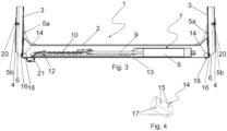
- FIG 3 shows a cross-sectional view of part of the timber bunk 1, the posts 3 being shown as cut.
- a load tightener 7 is installed inside the horizontal beam 2.
- the load tightener 7 may comprise a pneumatic or hydraulic cylinder 8 whose arm 9 is connected on the outside of the timber bunk 1 with a chain 10. At the end of the chain 10 there is usually a hook 11 ( Figure 5 ).
- the chain 10 is controlled with guide rolls 12 or similar.
- the cylinder 8 is kept in place by a retainer 13.
- the cylinder 8 is usually arranged to be controlled by the pneumatic or hydraulic system of a vehicle.
- the load tightener 7 may also be implemented in a different way than that described in the above.
- the pockets 4 are hollow on the inside and have an inner end surface 5a and outer end surface 5b in the longitudinal direction of the horizontal beam 2.
- the inner end surface 5a is outside the pocket 4, on the load side, and outer end surface 5b is outside the pocket, outside the load.
- the posts 3 are fixed to the pockets 4 by bolts, in other words the fastening of the posts 3 is detachable.
- the pockets 4 and the post 3 are so designed that when the bolts are being tightened the joint surfaces guide the posts 3 into the correct angle in relation to the horizontal beam 2.
- the outer end surface 5b of the pocket 4 comprises an opening 6 for the installation of a load tightener 7.
- the opening 6 is advantageously at the lower part of the pocket 4 so that it has a straight horizontal connection inside the horizontal beam 2.
- the opening 6 may be bevelled at the lower part of the pocket 4, on the inner end surface 5a side, obliquely up onto the outer end surface 5b side of the pocket 4.
- Figure 3 only shows part of the opening 6 because the posts 3 cover the opening 6.
- a load-receiving member which may be a load detent 14.
- the load detent 14 is placed on the mouth of the opening 6 and receives the stress that the load causes.
- the inner walls of the bunk 1 may be so shaped at the pocket 4 and/or the horizontal beam 2 so that inside the bunk 1 a space is formed which is compatible with the load detent 14.
- Both pockets 4 of the bunk 1 may have the opening 6 of the type referred to in the above, or just one pocket 4 of the bunk 1 may include the opening 6.
- Figure 4 shows a perspective view of a possible load detent 14.
- the load detent 14 has the shape of a cut wedge.
- the load detent 14 has holes 15 for bolts 16, and holes 17 for bolts 18.
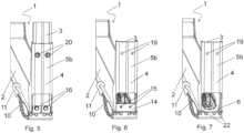
- Figure 5 shows a perspective view of a detail of a timber bunk 1 with the opening 6 closed.
- the post 3 is attached through holes 19 with bolts 20, and through holes 15 with bolts 16.
- the chain 10 and its hook 11 extend outside the horizontal beam 2 through an opening 21 ( Figure 3 ) at the bottom of the horizontal beam 2.
- Figure 6 shows a detail of the timber bunk when the opening 6 is open, but the load detent 14 is in place.
- Figure 7 shows a detail of the timber bunk 1 when the load detent 14 has been removed through an opened the opening 6.
- Figure 7 shows the holes 22 through which the bolts 18 are fastened to the load detent 14.
- the post 3 When the load tightener 7 is placed inside the horizontal beam 2 or removed from there, the post 3 is removed from the rest of the bunk 1 by removing the bolts 16 and 20. When the post 3 has been removed, the bolts 18 are opened whereby the load detent 14 comes out. After this, the load tightener 7 may be installed inside the horizontal beam 2 or removed from there.
Landscapes
- Engineering & Computer Science (AREA)
- Transportation (AREA)
- Mechanical Engineering (AREA)
- Chemical & Material Sciences (AREA)
- Combustion & Propulsion (AREA)
- Health & Medical Sciences (AREA)
- Public Health (AREA)
- Rod-Shaped Construction Members (AREA)
- Forms Removed On Construction Sites Or Auxiliary Members Thereof (AREA)
- Conveying And Assembling Of Building Elements In Situ (AREA)
Description
- The invention relates to a timber bunk comprising a horizontal beam both ends of which have a pocket where a substantially vertical post is arranged to be connected. The pocket has an inner end surface and an outer end surface in the longitudinal direction of the horizontal beam. The invention additionally relates to a method in connection with a timber bunk.
- Document
DE 2944102 discloses a long timber carrier that comprises upper and lower horizontal tubes and vertical supports at both ends of the tubes. The vertical supports are assembled through fasteners that are located in the ends of the upper and lower tubes. The long timber carrier is designed so that it can accommodate an elongated tightening device. The tightening device is inserted through an opening between the fasteners of the upper and lower tubes. - It is an object of the invention to present a new type of solution for timber bunks. The object of the invention is achieved by a timber bunk and method which are characterised by what is stated in the independent claims. Preferred embodiments of the invention are disclosed in the dependent claims.
- The invention is based on the bunk having a load-receiving member which allows an opening to be made in the pockets of the bunk. The benefit of the inventive timber bunk is that a load tightener may be placed inside the horizontal beam of the timber bunk, and that it may be removed from there for servicing and repairing purposes. The load-receiving member makes sure the strength of the bunk is maintained despite the opening.
- In the following, a timber bunk is explained it its operating position.
- The timber bunk comprises a hollow horizontal beam and two substantially vertical posts that are located at opposite sides of the horizontal beam. The horizontal beam and posts are usually of steel or aluminium. The timber bunk is usually secured to its base by two fasteners. A bunk structure may be installed either fixedly or movably to a body of a truck or trailer.
- At both ends of the horizontal beam there are pockets fixedly connected to the horizontal beam and fixed to the horizontal beam by welding, for example. The pockets are hollow on the inside and have an inner end surface and outer end surface in the longitudinal direction of the horizontal beam. In a use situation, the inner end surface is outside the pocket, on the load side, and the outer end surface is outside the pocket, outside the load. The posts are fixed to the pockets by bolting, in other words, the fastening of the posts is detachable. The pockets and the post are so designed that when the bolts are being tightened the joint surfaces guide the posts into the correct angle in relation to the horizontal beam.
- The outer end surface of the pocket comprises an opening for installing a load tightener. The opening is advantageously at a lower part of the pocket so that it has a straight horizontal connection inside the horizontal beam. The opening may be bevelled at the lower part of the pocket, on the inner end surface side, obliquely up onto the outer end surface side of the pocket.
- Inside the pocket, on its inner end surface side, there is a load-receiving member. The load-receiving member compensates for the weakening that the opening causes so that there will not be a weak spot in the bunk because of the opening. The load-receiving member is a load detent placed on the mouth of the opening. The inner walls of the bunk may be so shaped that a space is formed inside the bunk, which corresponds to the shape of the load detent and is therefore compatible with the load detent.
- Access inside the horizontal beam is achieved by first removing a post and then removing the load-receiving member. A load tightener may then be installed inside or removed from inside the horizontal beam.
- In a use situation, a load tightener is connected to chains installed over a timber load. A hook of the load tightener is fixed to the chain, and the chain is tightened with the load tightener. The load tightener is usually connected to the pneumatic or hydraulic system of a vehicle and consequently receives its driving force therefrom.
- The invention will now be described in closer detail in connection with the preferred embodiments, with reference to the accompanying drawings in which:
-
Figure 1 is a front view of a timber bunk; -
Figure 2 is a perspective view of a timber bunk; -
Figure 3 is a cross-section of part of a timber bunk; -
Figure 4 is a perspective view of a load detent; -
Figure 5 shows a perspective view of a detail of a timber bunk with the opening closed; -
Figure 6 shows a detail of a timber bunk with the opening opened; -
Figure 7 shows a detail of a timber bunk when the load detent removed through the opening. -
Figures 1 to 7 show the same embodiment of the invention. -
Figures 1 and 2 show atimber bunk 1 which comprises ahorizontal beam 2 hollow on the inside, two substantiallyvertical posts 3, and, at both ends of thehorizontal beam 2,pockets 4 fixed thereto. The longitudinal direction of thehorizontal beam 2 is the lateral direction of the vehicle. Thetimber bunk 1 is usually secured to its base by two fasteners. -
Figure 3 shows a cross-sectional view of part of thetimber bunk 1, theposts 3 being shown as cut. Aload tightener 7 is installed inside thehorizontal beam 2. Theload tightener 7 may comprise a pneumatic orhydraulic cylinder 8 whose arm 9 is connected on the outside of thetimber bunk 1 with achain 10. At the end of thechain 10 there is usually a hook 11 (Figure 5 ). Thechain 10 is controlled withguide rolls 12 or similar. Thecylinder 8 is kept in place by aretainer 13. Thecylinder 8 is usually arranged to be controlled by the pneumatic or hydraulic system of a vehicle. Theload tightener 7 may also be implemented in a different way than that described in the above. - The
pockets 4 are hollow on the inside and have aninner end surface 5a andouter end surface 5b in the longitudinal direction of thehorizontal beam 2. In a use situation, theinner end surface 5a is outside thepocket 4, on the load side, andouter end surface 5b is outside the pocket, outside the load. Theposts 3 are fixed to thepockets 4 by bolts, in other words the fastening of theposts 3 is detachable. Thepockets 4 and thepost 3 are so designed that when the bolts are being tightened the joint surfaces guide theposts 3 into the correct angle in relation to thehorizontal beam 2. - The
outer end surface 5b of thepocket 4 comprises anopening 6 for the installation of aload tightener 7. Theopening 6 is advantageously at the lower part of thepocket 4 so that it has a straight horizontal connection inside thehorizontal beam 2. Theopening 6 may be bevelled at the lower part of thepocket 4, on theinner end surface 5a side, obliquely up onto theouter end surface 5b side of thepocket 4.Figure 3 only shows part of theopening 6 because theposts 3 cover theopening 6. - Inside the
pocket 4, on the side of isinner end surface 5a, there is a load-receiving member which may be aload detent 14. Theload detent 14 is placed on the mouth of theopening 6 and receives the stress that the load causes. The inner walls of thebunk 1 may be so shaped at thepocket 4 and/or thehorizontal beam 2 so that inside the bunk 1 a space is formed which is compatible with theload detent 14. - Both
pockets 4 of thebunk 1 may have theopening 6 of the type referred to in the above, or just onepocket 4 of thebunk 1 may include theopening 6. -
Figure 4 shows a perspective view of apossible load detent 14. Theload detent 14 has the shape of a cut wedge. Theload detent 14 hasholes 15 forbolts 16, and holes 17 forbolts 18. -
Figure 5 shows a perspective view of a detail of atimber bunk 1 with theopening 6 closed. Thepost 3 is attached throughholes 19 withbolts 20, and throughholes 15 withbolts 16. Thechain 10 and itshook 11 extend outside thehorizontal beam 2 through an opening 21 (Figure 3 ) at the bottom of thehorizontal beam 2. -
Figure 6 shows a detail of the timber bunk when theopening 6 is open, but theload detent 14 is in place.Figure 7 , in turn, shows a detail of thetimber bunk 1 when theload detent 14 has been removed through an opened theopening 6.Figure 7 shows theholes 22 through which thebolts 18 are fastened to theload detent 14. - When the
load tightener 7 is placed inside thehorizontal beam 2 or removed from there, thepost 3 is removed from the rest of thebunk 1 by removing thebolts post 3 has been removed, thebolts 18 are opened whereby theload detent 14 comes out. After this, theload tightener 7 may be installed inside thehorizontal beam 2 or removed from there. - Those skilled in the art will find it obvious that, as technology advances, the basic idea of the invention may be implemented in many different ways. The invention and its embodiments are thus not restricted to the above-described examples but may vary as long they fall under the scope of the claims.
Claims (3)
- A timber bunk (1) comprising a horizontal beam (2) having a bottom and both ends of the horizontal beam (2) have a pocket (4) where a substantially vertical post (3) is connected, the pocket (4) having an inner end surface (5a) and an outer end surface (5b) in the longitudinal direction of the horizontal beam (2), characterized in that inside the pocket (4), on the side of its inner end surface (5a), a load detent (14) is detachably attached to the bottom of the horizontal beam (2) by bolt joints and the substantially vertical post (3) is attached to the load detent (14) and to the outer end surface (5b) of the pocket (4) by bolt joints, and the outer end surface (5b) of the pocket (4) comprises an opening (6) extending to the level of a lower edge of the horizontal beam (2) for installing a load tightener (7).
- A timber bunk as claimed in claim 1, characterized in that the opening (6) is formed by bevelling at the lower part of the pocket (4), on the inner end surface (5a) side, obliquely up onto the outer end surface (5b) side of the pocket (4).
- A method in connection with a timber bunk (1), the timber bunk (1) comprising a horizontal beam (2) having a bottom and both ends of the horizontal beam (2) have a pocket (4) where a substantially vertical post (3) is connected, said pocket (4) having, in the longitudinal direction of the horizontal beam (2), an inner end surface (5a) and an outer end surface (5b), characterized in that the outer end surface (5b) comprises an opening (6) extending to the level of a lower edge of the horizontal beam (2), wherein inside the pocket (4), on the side of its inner end surface (5a), a load detent (14) is detachably attached to the bottom of the horizontal beam (2) by bolt joints and the substantially vertical post (3) is attached to the load detent (14) and to the outer end surface (5b) of the pocket (4) by bolt joints, and the method being intended for removing a load tightener (7) from inside the horizontal beam (2) of the timber bunk (1), the method comprising- removing the substantially vertical post (3) by removing bolts (16, 20),- detaching the load detent (14) from the bottom of the horizontal beam (2) by removing bolts (18), and- taking out the load detent (14).
Applications Claiming Priority (1)
| Application Number | Priority Date | Filing Date | Title |
|---|---|---|---|
| FI20195377A FI128575B (en) | 2019-05-08 | 2019-05-08 | Timber bank and procedure in connection with a timber bank |
Publications (3)
| Publication Number | Publication Date |
|---|---|
| EP3738866A1 EP3738866A1 (en) | 2020-11-18 |
| EP3738866C0 EP3738866C0 (en) | 2025-02-12 |
| EP3738866B1 true EP3738866B1 (en) | 2025-02-12 |
Family
ID=70613578
Family Applications (1)
| Application Number | Title | Priority Date | Filing Date |
|---|---|---|---|
| EP20173098.3A Active EP3738866B1 (en) | 2019-05-08 | 2020-05-06 | Timber bunk and method in connection with timber bunk |
Country Status (3)
| Country | Link |
|---|---|
| EP (1) | EP3738866B1 (en) |
| FI (1) | FI128575B (en) |
| PL (1) | PL3738866T3 (en) |
Families Citing this family (1)
| Publication number | Priority date | Publication date | Assignee | Title |
|---|---|---|---|---|
| FI130951B1 (en) * | 2022-04-29 | 2024-06-14 | Simo Marttala Oy | Clamp, arrangement for securing the load of the means of transport and the means of transport |
Citations (1)
| Publication number | Priority date | Publication date | Assignee | Title |
|---|---|---|---|---|
| FI793484A7 (en) * | 1978-11-13 | 1980-05-14 | Laxo Mekan Ab | LOG BANQUE WITH SPAWN ORGAN |
-
2019
- 2019-05-08 FI FI20195377A patent/FI128575B/en active IP Right Grant
-
2020
- 2020-05-06 EP EP20173098.3A patent/EP3738866B1/en active Active
- 2020-05-06 PL PL20173098.3T patent/PL3738866T3/en unknown
Patent Citations (1)
| Publication number | Priority date | Publication date | Assignee | Title |
|---|---|---|---|---|
| FI793484A7 (en) * | 1978-11-13 | 1980-05-14 | Laxo Mekan Ab | LOG BANQUE WITH SPAWN ORGAN |
Also Published As
| Publication number | Publication date |
|---|---|
| EP3738866C0 (en) | 2025-02-12 |
| PL3738866T3 (en) | 2025-05-05 |
| EP3738866A1 (en) | 2020-11-18 |
| FI128575B (en) | 2020-08-14 |
| FI20195377A1 (en) | 2020-08-14 |
Similar Documents
| Publication | Publication Date | Title |
|---|---|---|
| CA3202035C (en) | Cargo body and method of assembling the same | |
| EP2558732B1 (en) | Suspension device for vehicle | |
| CA2741384C (en) | Interconnecting trailer side rail and tie down plate | |
| US6932398B2 (en) | Bumper having a hollow section and mounting brackets attached to it | |
| US20080252034A1 (en) | Running board bracket | |
| EA022827B1 (en) | Transport device | |
| EP2054246B1 (en) | A bumper beam for a vehicle | |
| EP3738866B1 (en) | Timber bunk and method in connection with timber bunk | |
| CN103085885A (en) | Reinforcing structure of back column part | |
| EP1688304B1 (en) | Load carrier for fixed roof rail | |
| EP2247469B1 (en) | Bumper beam for a vehicle. | |
| EP2768687B1 (en) | Bracket for a vehicle tank | |
| US7387481B2 (en) | Cargo box outer hook mounting structure | |
| CN100376455C (en) | Hauler for ship | |
| US5365855A (en) | Track for magnetic levitation trains with stator connection having shear loaded belts | |
| MX2014008421A (en) | Slider pin assembly with integral inboard and outboard stop. | |
| US8595935B2 (en) | Method of lifting a cab onto a chassis | |
| CN217719847U (en) | Box and whole car | |
| US20030214174A1 (en) | Tailgate assembly for an off-road truck | |
| US20070075554A1 (en) | Hood strut assembly and method of mounting hood strut assembly to a vehicle body and a vehicle hood | |
| KR20190041634A (en) | Clamping apparatus for fixing of cargo box in truck | |
| EP3548332B1 (en) | Transport platform | |
| JP7785311B1 (en) | Railroad vehicle fall prevention fence posts and railroad vehicle fall prevention fences | |
| KR200180126Y1 (en) | Car curbs for quay | |
| US12485982B1 (en) | Side rail for trailer |
Legal Events
| Date | Code | Title | Description |
|---|---|---|---|
| PUAI | Public reference made under article 153(3) epc to a published international application that has entered the european phase |
Free format text: ORIGINAL CODE: 0009012 |
|
| STAA | Information on the status of an ep patent application or granted ep patent |
Free format text: STATUS: THE APPLICATION HAS BEEN PUBLISHED |
|
| AK | Designated contracting states |
Kind code of ref document: A1 Designated state(s): AL AT BE BG CH CY CZ DE DK EE ES FI FR GB GR HR HU IE IS IT LI LT LU LV MC MK MT NL NO PL PT RO RS SE SI SK SM TR |
|
| AX | Request for extension of the european patent |
Extension state: BA ME |
|
| STAA | Information on the status of an ep patent application or granted ep patent |
Free format text: STATUS: REQUEST FOR EXAMINATION WAS MADE |
|
| 17P | Request for examination filed |
Effective date: 20210517 |
|
| RBV | Designated contracting states (corrected) |
Designated state(s): AL AT BE BG CH CY CZ DE DK EE ES FI FR GB GR HR HU IE IS IT LI LT LU LV MC MK MT NL NO PL PT RO RS SE SI SK SM TR |
|
| STAA | Information on the status of an ep patent application or granted ep patent |
Free format text: STATUS: EXAMINATION IS IN PROGRESS |
|
| 17Q | First examination report despatched |
Effective date: 20210906 |
|
| GRAP | Despatch of communication of intention to grant a patent |
Free format text: ORIGINAL CODE: EPIDOSNIGR1 |
|
| STAA | Information on the status of an ep patent application or granted ep patent |
Free format text: STATUS: GRANT OF PATENT IS INTENDED |
|
| GRAJ | Information related to disapproval of communication of intention to grant by the applicant or resumption of examination proceedings by the epo deleted |
Free format text: ORIGINAL CODE: EPIDOSDIGR1 |
|
| GRAP | Despatch of communication of intention to grant a patent |
Free format text: ORIGINAL CODE: EPIDOSNIGR1 |
|
| INTG | Intention to grant announced |
Effective date: 20240819 |
|
| INTG | Intention to grant announced |
Effective date: 20240902 |
|
| GRAS | Grant fee paid |
Free format text: ORIGINAL CODE: EPIDOSNIGR3 |
|
| GRAA | (expected) grant |
Free format text: ORIGINAL CODE: 0009210 |
|
| STAA | Information on the status of an ep patent application or granted ep patent |
Free format text: STATUS: THE PATENT HAS BEEN GRANTED |
|
| AK | Designated contracting states |
Kind code of ref document: B1 Designated state(s): AL AT BE BG CH CY CZ DE DK EE ES FI FR GB GR HR HU IE IS IT LI LT LU LV MC MK MT NL NO PL PT RO RS SE SI SK SM TR |
|
| REG | Reference to a national code |
Ref country code: GB Ref legal event code: FG4D |
|
| REG | Reference to a national code |
Ref country code: CH Ref legal event code: EP |
|
| REG | Reference to a national code |
Ref country code: DE Ref legal event code: R096 Ref document number: 602020045802 Country of ref document: DE |
|
| REG | Reference to a national code |
Ref country code: IE Ref legal event code: FG4D |
|
| U01 | Request for unitary effect filed |
Effective date: 20250303 |
|
| U07 | Unitary effect registered |
Designated state(s): AT BE BG DE DK EE FI FR IT LT LU LV MT NL PT RO SE SI Effective date: 20250311 |
|
| U20 | Renewal fee for the european patent with unitary effect paid |
Year of fee payment: 6 Effective date: 20250514 |
|
| PG25 | Lapsed in a contracting state [announced via postgrant information from national office to epo] |
Ref country code: RS Free format text: LAPSE BECAUSE OF FAILURE TO SUBMIT A TRANSLATION OF THE DESCRIPTION OR TO PAY THE FEE WITHIN THE PRESCRIBED TIME-LIMIT Effective date: 20250512 |
|
| PG25 | Lapsed in a contracting state [announced via postgrant information from national office to epo] |
Ref country code: ES Free format text: LAPSE BECAUSE OF FAILURE TO SUBMIT A TRANSLATION OF THE DESCRIPTION OR TO PAY THE FEE WITHIN THE PRESCRIBED TIME-LIMIT Effective date: 20250212 |
|
| PGFP | Annual fee paid to national office [announced via postgrant information from national office to epo] |
Ref country code: GB Payment date: 20250527 Year of fee payment: 6 |
|
| PG25 | Lapsed in a contracting state [announced via postgrant information from national office to epo] |
Ref country code: IS Free format text: LAPSE BECAUSE OF FAILURE TO SUBMIT A TRANSLATION OF THE DESCRIPTION OR TO PAY THE FEE WITHIN THE PRESCRIBED TIME-LIMIT Effective date: 20250612 Ref country code: NO Free format text: LAPSE BECAUSE OF FAILURE TO SUBMIT A TRANSLATION OF THE DESCRIPTION OR TO PAY THE FEE WITHIN THE PRESCRIBED TIME-LIMIT Effective date: 20250512 |
|
| PG25 | Lapsed in a contracting state [announced via postgrant information from national office to epo] |
Ref country code: HR Free format text: LAPSE BECAUSE OF FAILURE TO SUBMIT A TRANSLATION OF THE DESCRIPTION OR TO PAY THE FEE WITHIN THE PRESCRIBED TIME-LIMIT Effective date: 20250212 |
|
| PG25 | Lapsed in a contracting state [announced via postgrant information from national office to epo] |
Ref country code: GR Free format text: LAPSE BECAUSE OF FAILURE TO SUBMIT A TRANSLATION OF THE DESCRIPTION OR TO PAY THE FEE WITHIN THE PRESCRIBED TIME-LIMIT Effective date: 20250513 |
|
| PGFP | Annual fee paid to national office [announced via postgrant information from national office to epo] |
Ref country code: IE Payment date: 20250521 Year of fee payment: 6 |
|
| PG25 | Lapsed in a contracting state [announced via postgrant information from national office to epo] |
Ref country code: SM Free format text: LAPSE BECAUSE OF FAILURE TO SUBMIT A TRANSLATION OF THE DESCRIPTION OR TO PAY THE FEE WITHIN THE PRESCRIBED TIME-LIMIT Effective date: 20250212 |
|
| PGFP | Annual fee paid to national office [announced via postgrant information from national office to epo] |
Ref country code: PL Payment date: 20250503 Year of fee payment: 6 |
|
| PG25 | Lapsed in a contracting state [announced via postgrant information from national office to epo] |
Ref country code: CZ Free format text: LAPSE BECAUSE OF FAILURE TO SUBMIT A TRANSLATION OF THE DESCRIPTION OR TO PAY THE FEE WITHIN THE PRESCRIBED TIME-LIMIT Effective date: 20250212 |
|
| PG25 | Lapsed in a contracting state [announced via postgrant information from national office to epo] |
Ref country code: SK Free format text: LAPSE BECAUSE OF FAILURE TO SUBMIT A TRANSLATION OF THE DESCRIPTION OR TO PAY THE FEE WITHIN THE PRESCRIBED TIME-LIMIT Effective date: 20250212 |
|
| PLBE | No opposition filed within time limit |
Free format text: ORIGINAL CODE: 0009261 |
|
| STAA | Information on the status of an ep patent application or granted ep patent |
Free format text: STATUS: NO OPPOSITION FILED WITHIN TIME LIMIT |
|
| REG | Reference to a national code |
Ref country code: CH Ref legal event code: H13 Free format text: ST27 STATUS EVENT CODE: U-0-0-H10-H13 (AS PROVIDED BY THE NATIONAL OFFICE) Effective date: 20251223 |
|
| REG | Reference to a national code |
Ref country code: CH Ref legal event code: L10 Free format text: ST27 STATUS EVENT CODE: U-0-0-L10-L00 (AS PROVIDED BY THE NATIONAL OFFICE) Effective date: 20251224 |
|
| PG25 | Lapsed in a contracting state [announced via postgrant information from national office to epo] |
Ref country code: CH Free format text: LAPSE BECAUSE OF NON-PAYMENT OF DUE FEES Effective date: 20250531 |
|
| 26N | No opposition filed |
Effective date: 20251113 |
|
| PG25 | Lapsed in a contracting state [announced via postgrant information from national office to epo] |
Ref country code: MC Free format text: LAPSE BECAUSE OF FAILURE TO SUBMIT A TRANSLATION OF THE DESCRIPTION OR TO PAY THE FEE WITHIN THE PRESCRIBED TIME-LIMIT Effective date: 20250212 |