EP3738834B1 - Pièce de carrosserie automobile comprenant une région destinée a être placée en regard d'un radar - Google Patents
Pièce de carrosserie automobile comprenant une région destinée a être placée en regard d'un radar Download PDFInfo
- Publication number
- EP3738834B1 EP3738834B1 EP20174883.7A EP20174883A EP3738834B1 EP 3738834 B1 EP3738834 B1 EP 3738834B1 EP 20174883 A EP20174883 A EP 20174883A EP 3738834 B1 EP3738834 B1 EP 3738834B1
- Authority
- EP
- European Patent Office
- Prior art keywords
- region
- film
- thickness
- radar
- main body
- Prior art date
- Legal status (The legal status is an assumption and is not a legal conclusion. Google has not performed a legal analysis and makes no representation as to the accuracy of the status listed.)
- Active
Links
Images

Classifications
-
- B—PERFORMING OPERATIONS; TRANSPORTING
- B60—VEHICLES IN GENERAL
- B60R—VEHICLES, VEHICLE FITTINGS, OR VEHICLE PARTS, NOT OTHERWISE PROVIDED FOR
- B60R11/00—Arrangements for holding or mounting articles, not otherwise provided for
-
- B—PERFORMING OPERATIONS; TRANSPORTING
- B60—VEHICLES IN GENERAL
- B60R—VEHICLES, VEHICLE FITTINGS, OR VEHICLE PARTS, NOT OTHERWISE PROVIDED FOR
- B60R13/00—Elements for body-finishing, identifying, or decorating; Arrangements or adaptations for advertising purposes
- B60R13/04—External Ornamental or guard strips; Ornamental inscriptive devices thereon
-
- B—PERFORMING OPERATIONS; TRANSPORTING
- B60—VEHICLES IN GENERAL
- B60R—VEHICLES, VEHICLE FITTINGS, OR VEHICLE PARTS, NOT OTHERWISE PROVIDED FOR
- B60R19/00—Wheel guards; Radiator guards, e.g. grilles; Obstruction removers; Fittings damping bouncing force in collisions
- B60R19/02—Bumpers, i.e. impact receiving or absorbing members for protecting vehicles or fending off blows from other vehicles or objects
- B60R19/48—Bumpers, i.e. impact receiving or absorbing members for protecting vehicles or fending off blows from other vehicles or objects combined with, or convertible into, other devices or objects, e.g. bumpers combined with road brushes, bumpers convertible into beds
- B60R19/483—Bumpers, i.e. impact receiving or absorbing members for protecting vehicles or fending off blows from other vehicles or objects combined with, or convertible into, other devices or objects, e.g. bumpers combined with road brushes, bumpers convertible into beds with obstacle sensors of electric or electronic type
-
- B—PERFORMING OPERATIONS; TRANSPORTING
- B60—VEHICLES IN GENERAL
- B60S—SERVICING, CLEANING, REPAIRING, SUPPORTING, LIFTING, OR MANOEUVRING OF VEHICLES, NOT OTHERWISE PROVIDED FOR
- B60S1/00—Cleaning of vehicles
- B60S1/62—Other vehicle fittings for cleaning
- B60S1/66—Other vehicle fittings for cleaning for cleaning vehicle exterior
-
- G—PHYSICS
- G01—MEASURING; TESTING
- G01S—RADIO DIRECTION-FINDING; RADIO NAVIGATION; DETERMINING DISTANCE OR VELOCITY BY USE OF RADIO WAVES; LOCATING OR PRESENCE-DETECTING BY USE OF THE REFLECTION OR RERADIATION OF RADIO WAVES; ANALOGOUS ARRANGEMENTS USING OTHER WAVES
- G01S13/00—Systems using the reflection or reradiation of radio waves, e.g. radar systems; Analogous systems using reflection or reradiation of waves whose nature or wavelength is irrelevant or unspecified
- G01S13/88—Radar or analogous systems specially adapted for specific applications
- G01S13/93—Radar or analogous systems specially adapted for specific applications for anti-collision purposes
- G01S13/931—Radar or analogous systems specially adapted for specific applications for anti-collision purposes of land vehicles
-
- G—PHYSICS
- G01—MEASURING; TESTING
- G01S—RADIO DIRECTION-FINDING; RADIO NAVIGATION; DETERMINING DISTANCE OR VELOCITY BY USE OF RADIO WAVES; LOCATING OR PRESENCE-DETECTING BY USE OF THE REFLECTION OR RERADIATION OF RADIO WAVES; ANALOGOUS ARRANGEMENTS USING OTHER WAVES
- G01S7/00—Details of systems according to groups G01S13/00, G01S15/00, G01S17/00
- G01S7/02—Details of systems according to groups G01S13/00, G01S15/00, G01S17/00 of systems according to group G01S13/00
- G01S7/027—Constructional details of housings, e.g. form, type, material or ruggedness
-
- H—ELECTRICITY
- H01—ELECTRIC ELEMENTS
- H01Q—ANTENNAS, i.e. RADIO AERIALS
- H01Q1/00—Details of, or arrangements associated with, antennas
- H01Q1/02—Arrangements for de-icing; Arrangements for drying-out ; Arrangements for cooling; Arrangements for preventing corrosion
-
- H—ELECTRICITY
- H01—ELECTRIC ELEMENTS
- H01Q—ANTENNAS, i.e. RADIO AERIALS
- H01Q1/00—Details of, or arrangements associated with, antennas
- H01Q1/27—Adaptation for use in or on movable bodies
- H01Q1/32—Adaptation for use in or on road or rail vehicles
- H01Q1/3208—Adaptation for use in or on road or rail vehicles characterised by the application wherein the antenna is used
- H01Q1/3233—Adaptation for use in or on road or rail vehicles characterised by the application wherein the antenna is used particular used as part of a sensor or in a security system, e.g. for automotive radar, navigation systems
-
- H—ELECTRICITY
- H01—ELECTRIC ELEMENTS
- H01Q—ANTENNAS, i.e. RADIO AERIALS
- H01Q1/00—Details of, or arrangements associated with, antennas
- H01Q1/42—Housings not intimately mechanically associated with radiating elements, e.g. radome
-
- B—PERFORMING OPERATIONS; TRANSPORTING
- B60—VEHICLES IN GENERAL
- B60R—VEHICLES, VEHICLE FITTINGS, OR VEHICLE PARTS, NOT OTHERWISE PROVIDED FOR
- B60R11/00—Arrangements for holding or mounting articles, not otherwise provided for
- B60R2011/0001—Arrangements for holding or mounting articles, not otherwise provided for characterised by position
- B60R2011/004—Arrangements for holding or mounting articles, not otherwise provided for characterised by position outside the vehicle
-
- B—PERFORMING OPERATIONS; TRANSPORTING
- B60—VEHICLES IN GENERAL
- B60R—VEHICLES, VEHICLE FITTINGS, OR VEHICLE PARTS, NOT OTHERWISE PROVIDED FOR
- B60R11/00—Arrangements for holding or mounting articles, not otherwise provided for
- B60R2011/0042—Arrangements for holding or mounting articles, not otherwise provided for characterised by mounting means
- B60R2011/0049—Arrangements for holding or mounting articles, not otherwise provided for characterised by mounting means for non integrated articles
- B60R2011/005—Connection with the vehicle part
-
- B—PERFORMING OPERATIONS; TRANSPORTING
- B60—VEHICLES IN GENERAL
- B60R—VEHICLES, VEHICLE FITTINGS, OR VEHICLE PARTS, NOT OTHERWISE PROVIDED FOR
- B60R19/00—Wheel guards; Radiator guards, e.g. grilles; Obstruction removers; Fittings damping bouncing force in collisions
- B60R19/02—Bumpers, i.e. impact receiving or absorbing members for protecting vehicles or fending off blows from other vehicles or objects
- B60R19/18—Bumpers, i.e. impact receiving or absorbing members for protecting vehicles or fending off blows from other vehicles or objects characterised by the cross-section; Means within the bumper to absorb impact
- B60R2019/1886—Bumper fascias and fastening means therefor
-
- G—PHYSICS
- G01—MEASURING; TESTING
- G01S—RADIO DIRECTION-FINDING; RADIO NAVIGATION; DETERMINING DISTANCE OR VELOCITY BY USE OF RADIO WAVES; LOCATING OR PRESENCE-DETECTING BY USE OF THE REFLECTION OR RERADIATION OF RADIO WAVES; ANALOGOUS ARRANGEMENTS USING OTHER WAVES
- G01S13/00—Systems using the reflection or reradiation of radio waves, e.g. radar systems; Analogous systems using reflection or reradiation of waves whose nature or wavelength is irrelevant or unspecified
- G01S13/88—Radar or analogous systems specially adapted for specific applications
- G01S13/93—Radar or analogous systems specially adapted for specific applications for anti-collision purposes
- G01S13/931—Radar or analogous systems specially adapted for specific applications for anti-collision purposes of land vehicles
- G01S2013/9327—Sensor installation details
-
- G—PHYSICS
- G01—MEASURING; TESTING
- G01S—RADIO DIRECTION-FINDING; RADIO NAVIGATION; DETERMINING DISTANCE OR VELOCITY BY USE OF RADIO WAVES; LOCATING OR PRESENCE-DETECTING BY USE OF THE REFLECTION OR RERADIATION OF RADIO WAVES; ANALOGOUS ARRANGEMENTS USING OTHER WAVES
- G01S13/00—Systems using the reflection or reradiation of radio waves, e.g. radar systems; Analogous systems using reflection or reradiation of waves whose nature or wavelength is irrelevant or unspecified
- G01S13/88—Radar or analogous systems specially adapted for specific applications
- G01S13/93—Radar or analogous systems specially adapted for specific applications for anti-collision purposes
- G01S13/931—Radar or analogous systems specially adapted for specific applications for anti-collision purposes of land vehicles
- G01S2013/9327—Sensor installation details
- G01S2013/93271—Sensor installation details in the front of the vehicles
-
- G—PHYSICS
- G01—MEASURING; TESTING
- G01S—RADIO DIRECTION-FINDING; RADIO NAVIGATION; DETERMINING DISTANCE OR VELOCITY BY USE OF RADIO WAVES; LOCATING OR PRESENCE-DETECTING BY USE OF THE REFLECTION OR RERADIATION OF RADIO WAVES; ANALOGOUS ARRANGEMENTS USING OTHER WAVES
- G01S13/00—Systems using the reflection or reradiation of radio waves, e.g. radar systems; Analogous systems using reflection or reradiation of waves whose nature or wavelength is irrelevant or unspecified
- G01S13/88—Radar or analogous systems specially adapted for specific applications
- G01S13/93—Radar or analogous systems specially adapted for specific applications for anti-collision purposes
- G01S13/931—Radar or analogous systems specially adapted for specific applications for anti-collision purposes of land vehicles
- G01S2013/9327—Sensor installation details
- G01S2013/93275—Sensor installation details in the bumper area
-
- G—PHYSICS
- G01—MEASURING; TESTING
- G01S—RADIO DIRECTION-FINDING; RADIO NAVIGATION; DETERMINING DISTANCE OR VELOCITY BY USE OF RADIO WAVES; LOCATING OR PRESENCE-DETECTING BY USE OF THE REFLECTION OR RERADIATION OF RADIO WAVES; ANALOGOUS ARRANGEMENTS USING OTHER WAVES
- G01S7/00—Details of systems according to groups G01S13/00, G01S15/00, G01S17/00
- G01S7/02—Details of systems according to groups G01S13/00, G01S15/00, G01S17/00 of systems according to group G01S13/00
- G01S7/40—Means for monitoring or calibrating
- G01S7/4004—Means for monitoring or calibrating of parts of a radar system
- G01S7/4039—Means for monitoring or calibrating of parts of a radar system of sensor or antenna obstruction, e.g. dirt- or ice-coating
- G01S7/4043—Means for monitoring or calibrating of parts of a radar system of sensor or antenna obstruction, e.g. dirt- or ice-coating including means to prevent or remove the obstruction
- G01S7/4047—Heated dielectric lens, e.g. by heated wire
Definitions
- the invention relates to an automobile body part comprising a region intended to be placed facing a radar.
- Motor vehicle body parts are already known in the state of the art, comprising a part intended to be placed in front of a radar, or in other words having a radome function.
- the part of the bodywork part intended to be placed in front of the radar allows good transmission of the radar waves which pass through it.
- the bodywork parts have minimum thicknesses due to their manufacturing process.
- a known solution for improving the transparency to radar waves therefore consists in locally reducing the thickness of the part in the part forming the radome, to reach a thickness which makes it possible to optimize the attenuation of the waves to a minimum.
- this solution has several drawbacks, including a risk of defect in the appearance of the bodywork part, a complexification of the injection means and methods and a risk of embrittlement in the zone of lesser thickness.
- European demand EP 1 646 266 A2 which shows the preamble of claim 1, of US application US 2014093665 A1 and German demand DE 102013217391 A1 a bodywork part comprising an element (in the form of a heating film or a decorative element) intended to be positioned on the bodywork part, in front of a radar wave emission zone.
- the object of the invention is in particular to provide a motor vehicle body part comprising a region intended to be placed opposite a radar, in which this region has good transparency to radar waves, while being easy to manufacture and without aspect default.
- the subject of the invention is a motor vehicle body part according to claim 1.
- a bodywork part be of generally constant thickness to facilitate the injection of the part while obtaining a good surface appearance and it is also desired that the thickness of a bodywork part be low, in particular for reasons of vehicle weight, aesthetics, ease of implementation.
- the thickness of the part has been increased locally in the region intended to be placed in front of the radar, unlike the solutions known from the state of the art which consist in lowering the thickness in this region.
- a region intended to be placed facing a radar is a body part region capable of being traversed by the waves of a radar located on the vehicle.
- this region substantially corresponds to the projection of the cone formed by the waves of a radar on the bodywork part.
- peripheral zone of the region intended to be placed opposite a radar is formed by the part of the bodywork part situated around the region, and in the vicinity of the region.
- the main body is simple to manufacture and above all this body can be of constant geometry.
- this main body is obtained by injection molding, the shape of the mold is simple.
- the dealer has standard main bodies, and the thickness of the region intended to be placed in front of the radar is chosen and fixed easily thanks to films of appropriate thicknesses. More particularly, in the case where the part is painted, the optimum thickness of the region varies depending on the paint that is applied.
- the thickness of the region intended to be placed in front of a radar is chosen from a set of attenuation and reflection values of the radar waves/thickness of the region.
- This set of pairs is obtained for example by measurements and calculations of attenuation and reflection of the waves as a function of the thickness, and also as a function of parameters such as the dielectric properties of the materials used for the manufacture of the part, the paint applied to the surface of the part, in particular the different layers and their different thicknesses which make it possible to obtain a paint for automotive application, such as the primer, the base and the varnish.
- the choice of the thickness of the region is simple since it is made from a set of predetermined pairs.
- the invention also relates to a method of manufacturing an automobile body part according to one of the aforementioned embodiments, by molding a plastic material, said part comprising a region intended to be placed facing a radar, said region being thicker than a peripheral zone of the region, and in which an extra thickness is produced at the level of said region, the thickness of the region being chosen so that the attenuation of the radar waves at the level of the region is less than the attenuation of the radar waves at the level of the peripheral zone.
- the inventors have observed that the attenuation of the radar waves depends on the type of plastic material making up the main body and the film respectively, and also depends on the type of paint applied, for example a paint with a matte, pearly or metallic appearance. Thus, it is preferable to take these parameters into account when choosing the film to be applied.
- the figure 1 represents motor vehicle body part which is here a bumper 1 comprising regions 11 intended to be placed facing a radar, and a main body 10. It is understood that the motor vehicle body part according to the invention is not limited to a bumper, it can be another body part, for example a door, a roof, a tailgate, a wing.
- the radars placed behind the bodywork part can be of different types, for example SRR ("short range radar” in English) used for the detection of close obstacles, MRR (“mid range radar” in English), and LRR (“ long range radar” in English) used for driving assistance. These radars generally operate in the 76-77GHz and 77-81GHz frequency bands.
- the picture 2 is a partial view of a motor vehicle body part, on which is shown a region 11 intended to be placed opposite a radar, and the peripheral zone 13 of this region 11.
- the region 11 is thicker than the peripheral zone 13 of region 11, and the thickness of the region is chosen so that the attenuation of the radar waves at the level of the region is lower than the attenuation of the radar waves at the level of the peripheral zone 13.
- the thickness of region 11 is chosen from a set of radar wave attenuation and reflection values/thickness pairs. These torques are obtained through measurements and calculations of attenuation and reflection of radar waves or through simulations.
- This set of pairs is obtained for example by measurements and calculations of attenuation and reflection of the waves as a function of the thickness, and also as a function of parameters such as the dielectric properties of the materials used for the manufacture of the part, the paint applied to the surface of the part, in particular the different layers and their different thicknesses which make it possible to obtain a paint for automotive application, such as the primer, the base and the varnish.
- the bodywork part 1 comprises a main body 10 which comprises the region 11 intended to be placed facing a radar, and at least one film 12 applied as an extra thickness on said region 11.
- the film 12 comprises heating wires 16. These heating wires make it possible to defrost the region 11 to allow the radar to operate correctly. Indeed, the formation of frost or the presence of snow or ice on the region 11 greatly reduces the transparency to radar waves.
- the position of the wires is chosen so as not to interfere with the transmission of radar waves, in particular their spacing.
- the curved parts of the wires which could obstruct the transmission of radar waves, are placed outside the part which is precisely in front of the radar sensor, and which is represented by the dotted rectangle 17.
- the film 12 is held on the main body 10 by overmoulding.
- This embodiment is preferably used during the manufacture of the bodywork part in the factory, because it makes it possible to obtain parts having good resistance over time, and the manufacturing process is simple.
- the film 12 is held to the main body by an adhesive.
- This embodiment is more particularly useful when changing or repairing the body part, in particular at a car dealership.
- the dealer has a standard 10 main body, that is to say, which is the same for all vehicles of the same model, and a set of 12 films.
- the manufacture of the bodywork part 1 a film 12 is chosen according, in particular but in a non-limiting way, to the thickness of the main body 10, and more precisely to the thickness of the peripheral zone 13, of the nature the material making up the main body 10, the paint coating the outer face of the main body 10 (color, metallic, matte, pearly or other), the nature of the material of the film 12. It is then easily attached to the main body 10 using a suitable adhesive.
- the choice of the film by the person who produces the automobile part is preferably made from a predetermined list. After production of the part, and before its assembly on the vehicle, it is possible, if necessary, to check that the transmission and the reflection of the radar waves are done in an adequate manner, thanks to a device provided for this purpose.
- the main body 10 is made of polypropylene. This is generally the case when the bodywork part 1 is a bumper skin.
- the film 12 comprises a material chosen from polycarbonate, ABS/PC, PET, polyurethane, polyamide. These materials are easy to obtain in the form of films, and are capable of being attached to the polypropylene by overmolding or adhesion.
- the material of the main body 10 is chosen from polypropylene, polycarbonate, polymethyl methacrylate, a polyamide, polyethylene terephthalate (PET), a copolyester, acrylonitrile butadiene styrene, a mixture of acrylonitrile butadiene styrene and polycarbonate (ABS/PC), acrilonitrile styrene acrylate (ASA), styrene acrilonitrile, a mixture of acrylonitrile styrene acrylate and polycarbonate, a mixture of polycarbonate and polyethylene terephthalate, a mixture of polypropylene and EPDM.
- the main body 10 includes a zone for receiving the film 12 identified by a surface texturing or a slight and fine extra thickness on the edge 14 of the reception zone. This makes it possible to position the film 12 in the right place of the main body 10 while the body part is removed from the vehicle. Indeed, when the body part is removed from the vehicle, the position of the region 11 is not easy to know, because the radar is not fixed on the body part. If the film reception zone 12 is not identified, it is necessary that the film be of larger dimension to be sure to cover the entire area with positioning uncertainties.
- the main body 10 comprises a zone for receiving the film 12 which comprises an indexing 18.
- the film 12 comprises an indexing corresponding to the indexing 18 of the reception zone.
- This indexing 18 makes it possible to position the film 12 very precisely on the reception area. This is particularly useful for films provided with heating wires because the transparency to radar waves depends on the positioning of the wires.
- This indexing can take the form of an "ear” as represented on the figures 2 and 3 , but it can also take the form of a notch in the film 12, and of a shape corresponding to the notch on the reception area.
- the method of manufacturing the part comprises a step of molding a plastic material.
- the method comprises the production of an extra thickness in the region 11 of the part intended to be placed in front of a radar.
- the extra thickness is made with respect to the thickness of the peripheral zone 13 of the region 11.
- the thickness of the region 11 is chosen so that the attenuation of the radar waves at the level of the region 11 is less than l attenuation of the radar waves at the level of the peripheral zone 13. It is sought that this attenuation be minimal, and this is obtained by choosing the thickness of the region 11 from among couples attenuation value of the radar waves-thickness of the region 11, these pairs being predetermined for example by the method described above.
- step a) the face of the main body intended to be placed outside the vehicle is coated with paint.
- the main body is identical for all vehicles of the same model, and only one mold is therefore necessary for the main body, since the same part is always injected and then one or more films of the necessary thickness are added to obtain the overall thickness which gives the minimum radar wave attenuation and reflection.
- the choice of the thickness of the film 12 takes into account at least one of the following parameters: material of the main body 10, thickness of the region 11, material of the film 12 , paint applied to the main body 10.
- material of the main body 10 material of the main body 10
- material of the film 12 material of the film 12
- the inventors have found that the transmission of radar waves depends of course on the thickness of the components of the paint for automotive application, primer, base and varnish, and also on the color of the paint applied, as well as whether the paint is metallic, matte, pearlescent or otherwise.
- the paint is an important parameter in the choice of the film(s) to be applied in region 11.
Landscapes
- Engineering & Computer Science (AREA)
- Remote Sensing (AREA)
- Mechanical Engineering (AREA)
- Radar, Positioning & Navigation (AREA)
- Physics & Mathematics (AREA)
- General Physics & Mathematics (AREA)
- Computer Networks & Wireless Communication (AREA)
- Computer Security & Cryptography (AREA)
- Electromagnetism (AREA)
- Radar Systems Or Details Thereof (AREA)
- Laminated Bodies (AREA)
- Paints Or Removers (AREA)
- Manufacture Of Macromolecular Shaped Articles (AREA)
Description
- L'invention concerne une pièce de carrosserie automobile comprenant une région destinée à être placée en regard d'un radar.
- On connaît déjà dans l'état la technique, des pièces de carrosserie de véhicules automobiles comprenant une partie destinée à être placée devant un radar, ou autrement dit ayant une fonction de radôme. Ainsi, il est indispensable que la partie de la pièce de carrosserie destinée à être placée devant le radar permette une bonne transmission des ondes radar qui la traversent. Or, les pièces de carrosserie présentent des épaisseurs minimales dues à leur procédé de fabrication. Une solution connue pour améliorer la transparence aux ondes radar consiste donc à diminuer localement l'épaisseur de la pièce dans la partie formant radôme, pour atteindre une épaisseur qui permet d'optimiser l'atténuation des ondes à un minimum. Cependant cette solution présente plusieurs inconvénients, parmi lesquels un risque de défaut d'aspect de la pièce de carrosserie, une complexification des moyens et procédés d'injection et un risque de fragilisation dans la zone de moindre épaisseur.
- On connait de la demande européenne
EP 1 646 266 A2 , qui montre le préambule de la revendication 1, de la demande américaineUS 2014093665 A1 et de la demande allemandeDE 102013217391 A1 une pièce de carrosserie comprenant un élément (sous la forme d'un film chauffant ou d'un élément décoratif) destiné à être positionné sur la pièce de carrosserie, devant une zone d'émission d'ondes d'un radar. - L'invention a notamment pour but de fournir une pièce de carrosserie de véhicule automobile comprenant une région destinée à être placée en regard d'un radar, dans laquelle cette région possède une bonne transparence aux ondes radar, tout en étant facile à fabriquer et sans défaut d'aspect.
- A cet effet l'invention a pour objet une pièce de carrosserie de véhicule automobile selon la revendication 1.
- De manière inattendue, les inventeurs ont constaté que la transparence aux ondes radar d'une région d'une pièce de carrosserie placée en regard d'un radar peut être améliorée en augmentant l'épaisseur. Cependant, on souhaite qu'une pièce de carrosserie soit d'épaisseur généralement constante pour faciliter l'injection de la pièce tout en obtenant un bon aspect de surface et on souhaite aussi que l'épaisseur d'une pièce de carrosserie soit faible, en particulier pour des raisons de poids du véhicule, d'esthétique, de facilité de mise en œuvre. Ainsi, pour obtenir une transmission optimale des ondes radar dans la région d'une pièce de carrosserie destinée à être placée dans un radar, tout en conservant une pièce de carrosserie d'épaisseur faible, l'épaisseur de la pièce a été augmentée localement dans la région destinée à être placée devant le radar, contrairement aux solutions connues de l'état de la technique qui consistent à abaisser l'épaisseur dans cette région.
- Au sens de l'invention, une région destinée à être placée en regard d'un radar, est une région de pièce de carrosserie susceptible d'être traversée par les ondes d'un radar situé sur le véhicule. Ainsi cette région correspond sensiblement à la projection du cône formé par les ondes d'un radar sur la pièce de carrosserie.
- On comprend que la « zone périphérique » de la région destinée à être placée en regard d'un radar est formée par la partie de la pièce de carrosserie située autour de la région, et au voisinage de la région.
- Ainsi, le corps principal est simple à fabriquer et surtout ce corps peut être de géométrie constante. En particulier, lorsque ce corps principal est obtenu par moulage par injection, la forme du moule est simple. De plus, en cas de remplacement d'une pièce de carrosserie chez un concessionnaire, le concessionnaire dispose de corps principaux standards, et l'épaisseur de la région destinée à être placée devant le radar est choisie et fixée aisément grâce à des films d'épaisseurs adaptées. Plus particulièrement, dans le cas où la pièce est peinte, l'épaisseur optimale de la région varie en fonction de la peinture qui est appliquée.
- Dans un mode de réalisation, l'épaisseur de la région destinée à être placée devant un radar est choisie à partir d'un ensemble de couples valeurs d'atténuation et de réflexion des ondes radar / épaisseur de la région.
Cet ensemble de couples est obtenu par exemple par des mesures et calculs d'atténuation et réflexion des ondes en fonction de l'épaisseur, et également en fonction de paramètres tels que les propriétés diélectriques des matériaux utilisés pour la fabrication de la pièce, la peinture appliquée sur la surface de la pièce, notamment les différentes couches et leurs différentes épaisseurs qui permettent d'obtenir une peinture pour application automobile, telles que le primaire, la base et le vernis. Ainsi, le choix de l'épaisseur de la région est simple puisqu'il se fait parmi un ensemble de couples prédéterminés. - Suivant d'autres caractéristiques optionnelles de la pièce de carrosserie prises seules ou en combinaison :
- le corps principal comprend une zone de réception du film positionnée dans la région destinée à être placée en regard d'un radar, et l'épaisseur de la zone de réception du film est sensiblement identique à l'épaisseur de la région périphérique.
- le film comprend des fils chauffants. Cela permet en particulier de dégivrer la région de la pièce de carrosserie placée devant le radar. Les fils sont disposés de manière à conserver la transparence de la région aux ondes radar.
- le film est maintenu sur le corps principal par un adhésif. Ainsi, le montage du film sur le corps principal est aisé, et peut être facilement réalisé dans une concession automobile, lors d'un changement ou d'une réparation de la pièce de carrosserie par exemple.
- le film est maintenu sur le corps principal par surmoulage. Le surmoulage est particulièrement indiqué lors de la fabrication de la pièce de carrosserie en usine, et permet d'éviter l'utilisation d'adhésifs qui peuvent ne pas être très stables dans le temps.
- le matériau du corps principal est choisi parmi le polypropylène, le polycarbonate, le polyméthacrylate de méthyle, un polyamide, le polytéréphtalate d'éthylène (PET), un copolyester, l'acrylonitrile butadiène styrène, un mélange d'acrylonitrile butadiène styrène et de polycarbonate (ABS/PC), l'acrilonitrile styrène acrylate (ASA), le styrène acrilonitrile, un mélange d'acrilonitrile styrène acrylate et de polycarbonate, un mélange de polycarbonate et polytéréphtalate d'éthylène, un mélange de polypropylène et d'EPDM, et le film comprend un matériau choisi parmi du polycarbonate, de l'ABS/PC, du PET, du polyuréthane, du polyamide.
- la face de la pièce de carrosserie destinée à être placée à l'extérieur du véhicule est revêtue d'une peinture.
- L'invention a également pour objet un procédé de fabrication d'une pièce de carrosserie automobile selon l'un des modes de réalisation susmentionnés, par moulage d'une matière plastique, ladite pièce comprenant une région destinée à être placée en regard d'un radar, ladite région étant plus épaisse qu'une zone périphérique de la région, et dans lequel on réalise une surépaisseur au niveau de ladite région, l'épaisseur de la région étant choisie de manière à ce que l'atténuation des ondes radar au niveau de la région soit inférieure à l'atténuation des ondes radar au niveau de la zone périphérique.
- Suivant d'autres caractéristiques optionnelles du procédé de fabrication d'une pièce de carrosserie prises seules ou en combinaison :
- le procédé de fabrication d'une pièce de carrosserie automobile comprend les étapes suivantes :
- a) on fabrique un corps principal de la pièce de carrosserie par moulage,
- b) on choisit un film d'épaisseur appropriée parmi un ensemble de films, ou on choisit un nombre de films d'épaisseurs appropriées,
- c) on fixe le ou les films choisis dans la région du corps principal destinée à être placée en regard d'un radar.
- Ainsi, un seul moule est nécessaire pour la fabrication du corps principal, puisque l'on injecte toujours la même pièce et ensuite on ajoute un film d'épaisseur nécessaire pour obtenir l'épaisseur globale qui donne l'atténuation minimale.
- entre l'étape a) et l'étape b) on revêt la face du corps principal destinée à être placée à l'extérieur du véhicule d'une peinture. Cette peinture comprend généralement plusieurs épaisseurs de composants, tels que primaire, base et vernis, pour former cette épaisseur de peinture pour application automobile.
- l'épaisseur de la région est choisie à partir d'un ensemble de couples valeurs d'atténuation et de réflexion des ondes radar / épaisseur de la région.
- à l'étape b) le choix de l'épaisseur du film prend en compte au moins l'un des paramètres suivants : matériau du corps principal, épaisseur de la région, matériau du film, peinture appliquée sur le corps principal.
- En effet, les inventeurs ont constaté que l'atténuation des ondes radar dépend du type de matériau plastique composant respectivement le corps principal le film, et dépend également du type de peinture appliquée, par exemple une peinture à aspect mat, nacré ou métallisé. Ainsi, il est préférable de tenir compte de ces paramètres pour le choix du film à appliquer.
- L'invention sera mieux comprise à la lecture de la description qui va suivre donnée uniquement à titre d'exemple et faite en se référant aux dessins annexés dans lesquels :
- [
Fig. 1 ] Lafigure 1 est une vue en perspective schématique d'une pièce de carrosserie d'un véhicule automobile selon un premier mode de réalisation de l'invention ; - [
Fig. 2 ] Lafigure 2 est une vue d'arrière d'une portion de pièce de carrosserie selon le mode de réalisation de lafigure 1 ; - [
Fig. 3 ] Lafigure 3 est une vue d'arrière d'une portion de pièce de carrosserie selon un autre mode de réalisation ; - [
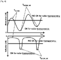
Fig. 4 ] Lafigure 4 représente des graphes d'atténuation et de réflexion des ondes radar en fonction d'une épaisseur d'un matériau plastique. - On a représenté sur les
figures 1 et 2 une pièce de carrosserie d'un véhicule automobile selon un mode de réalisation de l'invention, désignée par la référence générale 1. - La
figure 1 représente pièce de carrosserie de véhicule automobile qui est ici un pare-chocs 1 comprenant des régions 11 destinées à être placées en regard d'un radar, et un corps principal 10. On comprend que la pièce de carrosserie de véhicule automobile selon l'invention n'est pas limitée à un pare-chocs, il peut s'agir d'une autre pièce de carrosserie, par exemple une porte, un toit, un hayon, une aile. - Les radars placés derrière la pièce de carrosserie peuvent être de différents types, par exemple SRR (« short range radar » en anglais) utilisés pour les détections d'obstacles proches, MRR (« mid range radar » en anglais), et LRR (« long range radar » en anglais) utilisés pour l'assistance à la conduite. Ces radars fonctionnent généralement dans les bandes de fréquence 76-77GHz et 77-81GHz.
- La
figure 2 est une vue partielle d'une pièce de carrosserie de véhicule automobile, sur laquelle est représentée une région 11 destinée à être placée en regard d'un radar, et la zone périphérique 13 de cette région 11. La région 11 est plus épaisse que la zone périphérique 13 de la région 11, et l'épaisseur de la région est choisie de manière à ce que l'atténuation des ondes radar au niveau de la région soit inférieure à l'atténuation des ondes radar au niveau de la zone périphérique 13. - Plus précisément, l'épaisseur de la région 11 est choisie à partir d'un ensemble de couples valeurs d'atténuation et réflexion des ondes radar / épaisseur. Ces couples sont obtenus grâce à des mesures et calculs d'atténuation et réflexion des ondes radars ou bien par des simulations.
- Cet ensemble de couples est obtenu par exemple par des mesures et calculs d'atténuation et réflexion des ondes en fonction de l'épaisseur, et également en fonction de paramètres tels que les propriétés diélectriques des matériaux utilisés pour la fabrication de la pièce, la peinture appliquée sur la surface de la pièce, notamment les différentes couches et leurs différentes épaisseurs qui permettent d'obtenir une peinture pour application automobile, telles que le primaire, la base et le vernis.
- Selon l'invention, la pièce de carrosserie 1 comprend un corps principal 10 qui comporte la région 11 destinée à être placée en regard d'un radar, et au moins un film 12 rapporté en surépaisseur sur ladite région 11.
- Ceci est particulièrement avantageux, car on permet de simplifier la fabrication de la pièce de carrosserie, du fait que la surépaisseur de la région 11 est formée très facilement en fixant un film 12 d'épaisseur prédéterminée. Ainsi, il n'est pas nécessaire d'adapter la forme du corps principal 10 de la pièce de carrosserie en fonction, par exemple, de la peinture qui sera ensuite appliquée.
- A titre d'exemple, les mesures d'atténuation et de réflexion permettant d'obtenir les couples transparence aux ondes radar-épaisseur sont faites de la manière suivante :
- on obtient une pièce de carrosserie, ou un échantillon représentatif d'une pièce de carrosserie (c'est-à-dire fabriqué dans le même matériau, par le même procédé, et d'une épaisseur similaire à celle de la zone périphérique 13, et éventuellement peint) ;
- on fixe un film pris parmi un ensemble de films à tester sur la pièce ou l'échantillon de pièce, pour obtenir une région 11 ;
- on mesure la transmission et la réflexion des ondes radar à travers la région 11 ;
- on sélectionne le ou les films présentant des propriétés de transparence aux ondes radar satisfaisantes ;
- on recommence autant de fois que nécessaire, en particulier on effectue des mesures sur des pièces ou échantillons de pièces revêtus de différentes peintures.
- A titre d'exemple, on a représenté schématiquement sur la
figure 4 des allures de courbes présentant respectivement la valeur de l'atténuation des ondes radar (en dB) en fonction de l'épaisseur traversée par les ondes, et la valeur de la réflexion des ondes en fonction de l'épaisseur traversée par les ondes. Comme cela est visible, la courbe de l'atténuation présente des minimums d'atténuation pour des épaisseurs données, et pour ces mêmes épaisseurs la réflexion est également minimale. Ainsi, cela permet de déterminer l'épaisseur optimale de la région 11. - Dans un mode de réalisation particulier représenté par la
figure 3 , le film 12 comprend des fils chauffants 16. Ces fils chauffants permettent de dégivrer la région 11 pour permettre au radar de fonctionner correctement. En effet, la formation de givre ou la présence de neige ou de glace sur la région 11 diminue fortement la transparence aux ondes radar. - La position des fils est choisie de manière à ne pas gêner la transmission des ondes radar, en particulier leur espacement. D'autre part, ainsi que cela est visible sur la
figure 3 , les parties courbes des fils, qui pourraient faire obstacle à la transmission des ondes radars sont placées à l'extérieur de la partie qui se trouve précisément devant le capteur radar, et qui est représentée par le rectangle en pointillés 17. - Dans un mode de réalisation, le film 12 est maintenu sur le corps principal 10 par surmoulage. Ce mode de réalisation est préférentiellement utilisé lors de la fabrication de la pièce de carrosserie en usine, car il permet d'obtenir des pièces ayant une bonne tenue dans le temps, et le procédé de fabrication est simple.
- Dans un autre mode de réalisation, le film 12 est maintenu sur le corps principal par un adhésif. Ce mode de réalisation est plus particulièrement utile lors du changement ou de la réparation de la pièce de carrosserie, en particulier chez un concessionnaire automobile. En effet, dans ce cas, le concessionnaire dispose d'un corps principal 10 standard, c'est-à-dire qui est le même pour tous les véhicules d'un même modèle, et d'un ensemble de films 12. Lors de la fabrication de la pièce de carrosserie 1, un film 12 est choisi en fonction, en particulier mais de manière non limitative, de l'épaisseur du corps principal 10, et plus précisément de l'épaisseur de la zone périphérique 13, de la nature du matériau composant le corps principal 10, de la peinture revêtant la face extérieure du corps principal 10 (couleur, métallisée, mat, nacré ou autre), de la nature du matériau du film 12. Il est ensuite aisément fixé sur le corps principal 10 à l'aide d'un adhésif approprié. Le choix du film par la personne qui réalise la pièce automobile se fait de préférence dans une liste prédéterminée. Après réalisation de la pièce, et avant son montage sur le véhicule, on peut, si nécessaire, vérifier que la transmission et la réflexion des ondes radar se fait de manière adéquate, grâce à un appareil prévu à cet effet.
- Dans un mode de réalisation, le corps principal 10 est composé de polypropylène. C'est généralement le cas lorsque la pièce de carrosserie 1 est une peau de pare-chocs. Le film 12 comprend un matériau choisi parmi du polycarbonate, de l'ABS/PC, du PET, du polyuréthane, du polyamide. Ces matériaux sont faciles à obtenir sous forme de films, et sont aptes à être fixés sur le polypropylène par surmoulage ou adhésion.
- Dans d'autres modes de réalisation, le matériau du corps principal 10 est choisi parmi le polypropylène, le polycarbonate, le polyméthacrylate de méthyle, un polyamide, le polytéréphtalate d'éthylène (PET), un copolyester, l'acrylonitrile butadiène styrène, un mélange d'acrylonitrile butadiène styrène et de polycarbonate (ABS/PC), l'acrilonitrile styrène acrylate (ASA), le styrène acrilonitrile, un mélange d'acrilonitrile styrène acrylate et de polycarbonate, un mélange de polycarbonate et polytéréphtalate d'éthylène, un mélange de polypropylène et d'EPDM.
- Selon l'invention, le corps principal 10 comporte une zone de réception du film 12 identifiée par une texturation de surface ou une légère et fine surépaisseur sur la bordure 14 de la zone de réception. Cela permet de positionner la film 12 au bon endroit du corps principal 10 alors que la pièce de carrosserie est démontée du véhicule. En effet, lorsque la pièce de carrosserie est démontée du véhicule, la position de la région 11 n'est pas facile à connaitre, car le radar n'est pas fixé sur la pièce de carrosserie. Si la zone de réception du film 12 n'est pas identifiée, il est nécessaire que le film soit de plus grande dimension pour être certain de couvrir toute la zone avec les incertitudes de positionnement.
- Dans un autre mode de réalisation, le corps principal 10 comporte une zone de réception du film 12 qui comprend une indexation 18. Le film 12 comprend une indexation correspondante à l'indexation 18 de la zone de réception. Cette indexation 18 permet de positionner le film 12 de manière très précise sur la zone de réception. Cela est particulièrement utile pour les films pourvus de fils chauffants car la transparence aux ondes radar dépend du positionnement des fils. Cette indexation peut prendre la forme d'une « oreille » comme représenté sur les
figures 2 et 3 , mais elle peut également prendre la forme d'une encoche dans le film 12, et d'une forme correspondante à l'encoche sur la zone de réception. - Nous allons à présent décrire le procédé de fabrication d'une pièce de carrosserie 1 de véhicule automobile selon l'invention.
- De préférence, le procédé de fabrication de la pièce de comprend une étape de moulage d'une matière plastique. Le procédé comprend la réalisation d'une surépaisseur dans la région 11 de la pièce destinée à être placée devant un radar. La surépaisseur est réalisée par rapport à l'épaisseur de la zone périphérique 13 de la région 11. L'épaisseur de la région 11 est choisie de manière à ce que l'atténuation des ondes radar au niveau de la région 11 soit inférieure à l'atténuation des ondes radar au niveau de la zone périphérique 13. On cherche à ce que cette atténuation soit minimale, et ceci est obtenu en choisissant l'épaisseur de la région 11 parmi des couples valeur d'atténuation des ondes radar-épaisseur de la région 11, ces couples étant prédéterminée par exemple par la méthode décrite ci-dessus.
- Dans un mode de réalisation particulier, le procédé de fabrication d'une pièce de carrosserie 1 de véhicule automobile comprend les étapes suivantes :
- a) on approvisionne un corps principal 10,
- b) on choisit un film 12 d'épaisseur appropriée parmi un ensemble de films, ou on choisit un nombre de films 12 d'épaisseurs appropriées,
- c) on fixe le ou les films 12 choisis dans la région 11 du corps principal 10 destinée à être placée en regard d'un radar.
- Très fréquemment, entre l'étape a) et l'étape b) on revêt la face du corps principal destinée à être placée à l'extérieur du véhicule d'une peinture.
- Ainsi, le corps principal est identique pour tous les véhicule de même modèle, et un seul moule est donc nécessaire pour le corps principal, puisque l'on injecte toujours la même pièce et on ajoute ensuite un ou des films d'épaisseur nécessaire pour obtenir l'épaisseur globale qui donne l'atténuation et la réflexion des ondes radar minimales.
- En outre, à l'étape b) ci-dessus, le choix de l'épaisseur du film 12 prend en compte au moins l'un des paramètres suivants : matériau du corps principal 10, épaisseur de la région 11, matériau du film 12, peinture appliquée sur le corps principal 10. En effet, les inventeurs ont constaté que la transmission des ondes radar dépend bien sûr de l'épaisseur des composants de la peinture pour application automobile, primaire, base et vernis, et aussi de la couleur de la peinture appliquée, ainsi que du fait que la peinture soit métallisée, mat, nacrée ou autre. Ainsi, la peinture est un paramètre important dans le choix du ou des films à appliquer dans la région 11.
-
- 1 :
- Pièce de carrosserie
- 10 :
- Corps principal
- 11 :
- Région destinée à être placée en regard d'un radar
- 12 :
- Film (d'augmentation de l'épaisseur de la région 11)
- 13 :
- Zone périphérique de la région 11
- 14 :
- Bordure de la zone de réception du film 12 sur le corps 10
- 15 :
- Bordure du film 12
- 16 :
- Fils chauffants
- 17 :
- Zone placée devant le capteur radar
- 18 :
- Indexation de la zone de réception du film
Claims (14)
- Pièce de carrosserie (1) de véhicule automobile comprenant une région (11) destinée à être placée en regard d'un radar, la région (11) étant plus épaisse qu'une zone périphérique (13) de la région (11), caractérisée en ce que l'épaisseur de la région (11) est choisie de manière à ce que l'atténuation des ondes radar au niveau de la région (11) soit inférieure à l'atténuation des ondes radar au niveau de la zone périphérique (13), la pièce de carrosserie (1) comprenant un corps principal (10) qui comporte la région (11) destinée à être placée en regard d'un radar, et au moins un film (12) rapporté sur ladite région (11), le corps principal (10) comportant une zone de réception du film (12) identifiée par une texturation sur la zone de réception ou une légère et fine surépaisseur ou une texturation uniquement sur la bordure (14) de la zone de réception.
- Pièce de carrosserie (1) selon la revendication 1, dans laquelle l'épaisseur de la région (11) est choisie à partir d'un ensemble de couples valeurs d'atténuation et réflexion des ondes radar / épaisseur de la région (11).
- Pièce de carrosserie (1) selon la revendication 1 ou 2, dans laquelle le corps principal comprend une zone de réception du film (12) positionnée dans la région (11), et l'épaisseur de la zone de réception du film (12) est sensiblement identique à l'épaisseur de la région périphérique (13).
- Pièce de carrosserie (1) selon l'une quelconque des revendications précédentes, dans laquelle le film (12) comprend des fils chauffants (16).
- Pièce de carrosserie (1) selon l'une quelconque des revendications précédentes, dans laquelle le film (12) est maintenu sur le corps principal (10) par un adhésif.
- Pièce de carrosserie (1) selon l'une quelconque des revendications 1 à 4, dans laquelle le film (12) est maintenu sur le corps principal (10) par surmoulage.
- Pièce de carrosserie (1) selon l'une quelconque des revendications précédentes, dans laquelle le corps principal (10) comporte une zone de réception du film (12) qui comprend une indexation (18).
- Pièce de carrosserie (1) selon l'une quelconque des revendications précédentes, dans laquelle le matériau du corps principal (10) est choisi parmi le polypropylène, le polycarbonate, le polyméthacrylate de méthyle, un polyamide, le polytéréphtalate d'éthylène (PET), un copolyester, l'acrylonitrile butadiène styrène, un mélange d'acrylonitrile butadiène styrène et de polycarbonate (ABS/PC), l'acrilonitrile styrène acrylate (ASA), le styrène acrilonitrile, un mélange d'acrilonitrile styrène acrylate et de polycarbonate, un mélange de polycarbonate et polytéréphtalate d'éthylène, un mélange de polypropylène et d'EPDM, et le film (12) comprend un matériau choisi parmi du polycarbonate, de l'ABS/PC, du PET, du polyuréthane, du polyamide.
- Pièce de carrosserie (1) de véhicule automobile selon l'une quelconque des revendications précédentes, dans laquelle la face de la pièce de carrosserie destinée à être placée à l'extérieur de véhicule est revêtue d'une peinture.
- Procédé de fabrication d'une pièce de carrosserie (1) de véhicule automobile, selon l'une quelconque des revendications précédentes, par moulage d'une matière plastique, ladite pièce (1) comprenant une région (11) destinée à être placée en regard d'un radar, ladite région (11) étant plus épaisse qu'une zone périphérique (13) de la région (11), caractérisé en ce qu'on réalise une surépaisseur au niveau de ladite région (11), l'épaisseur de la région étant choisie de manière à ce que l'atténuation des ondes radar au niveau de la région (11) soit inférieure à l'atténuation des ondes radar au niveau de la zone périphérique (13).
- Procédé de fabrication d'une pièce de carrosserie (1) selon la revendication 10, dans lequel :a) on fabrique un corps principal (10) de la pièce de carrosserie par moulage,b) on choisit un film (12) d'épaisseur appropriée parmi un ensemble de films, ou on choisit un nombre de films d'épaisseurs appropriées,c) on fixe le ou les films (12) choisis dans la région (11) du corps principal (10) destinée à être placée en regard d'un radar.
- Procédé de fabrication selon la revendication 11, dans lequel entre l'étape a) et l'étape b) on revêt la face de la pièce de carrosserie (1) destinée à être placée à l'extérieur du véhicule d'une peinture.
- Procédé de fabrication selon l'une des revendications 10 à 12 dans laquelle l'épaisseur de la région (11) est choisie à partir d'un ensemble de couples valeurs d'atténuation et de réflexion des ondes radar / épaisseur de la région.
- Procédé de fabrication selon l'une des revendications 11 à 13 dans lequel à l'étape b) le choix de l'épaisseur du film (12) prend en compte au moins l'un des paramètres suivants: matériau du corps principal (10), épaisseur de la région (11), matériau du film (12), peinture appliquée sur le corps principal (10).
Applications Claiming Priority (1)
| Application Number | Priority Date | Filing Date | Title |
|---|---|---|---|
| FR1905199A FR3096002B1 (fr) | 2019-05-17 | 2019-05-17 | Pièce de carrosserie automobile comprenant une région destinée à être placée en regard d’un radar |
Publications (2)
| Publication Number | Publication Date |
|---|---|
| EP3738834A1 EP3738834A1 (fr) | 2020-11-18 |
| EP3738834B1 true EP3738834B1 (fr) | 2022-06-29 |
Family
ID=67999824
Family Applications (1)
| Application Number | Title | Priority Date | Filing Date |
|---|---|---|---|
| EP20174883.7A Active EP3738834B1 (fr) | 2019-05-17 | 2020-05-15 | Pièce de carrosserie automobile comprenant une région destinée a être placée en regard d'un radar |
Country Status (3)
| Country | Link |
|---|---|
| EP (1) | EP3738834B1 (fr) |
| CN (2) | CN111942299B (fr) |
| FR (1) | FR3096002B1 (fr) |
Families Citing this family (2)
| Publication number | Priority date | Publication date | Assignee | Title |
|---|---|---|---|---|
| FR3096002B1 (fr) * | 2019-05-17 | 2021-05-14 | Plastic Omnium Cie | Pièce de carrosserie automobile comprenant une région destinée à être placée en regard d’un radar |
| FR3117988B1 (fr) * | 2020-12-23 | 2023-08-25 | Cie Plastic Omnium Se | Pièce de carrosserie de véhicule automobile |
Family Cites Families (5)
| Publication number | Priority date | Publication date | Assignee | Title |
|---|---|---|---|---|
| DE102004049148A1 (de) * | 2004-10-07 | 2006-04-13 | Rehau Ag + Co | Heizungselement auf einer polymeren Innenoberfläche eines Frontmoduls/Stoßfängers eines Kraftfahrzeuges in Wirkverbindung mit einer Radarsende- und - empfangseinheit |
| US8702135B2 (en) * | 2012-09-04 | 2014-04-22 | Ford Global Technologies, Llc | Radar compatible automotive badge and fascia |
| JP2014069634A (ja) * | 2012-09-28 | 2014-04-21 | Toyoda Gosei Co Ltd | 車両用加飾部材 |
| CN103956573B (zh) * | 2014-05-21 | 2016-02-24 | 湖州泰和汽车零部件有限公司 | 一种雷达保护罩的制备方法 |
| FR3096002B1 (fr) * | 2019-05-17 | 2021-05-14 | Plastic Omnium Cie | Pièce de carrosserie automobile comprenant une région destinée à être placée en regard d’un radar |
-
2019
- 2019-05-17 FR FR1905199A patent/FR3096002B1/fr not_active Expired - Fee Related
-
2020
- 2020-05-15 EP EP20174883.7A patent/EP3738834B1/fr active Active
- 2020-05-18 CN CN202010417400.8A patent/CN111942299B/zh active Active
- 2020-05-18 CN CN202020822495.7U patent/CN213138641U/zh not_active Withdrawn - After Issue
Also Published As
| Publication number | Publication date |
|---|---|
| FR3096002B1 (fr) | 2021-05-14 |
| CN111942299B (zh) | 2025-09-19 |
| FR3096002A1 (fr) | 2020-11-20 |
| CN111942299A (zh) | 2020-11-17 |
| EP3738834A1 (fr) | 2020-11-18 |
| CN213138641U (zh) | 2021-05-07 |
Similar Documents
| Publication | Publication Date | Title |
|---|---|---|
| EP3738834B1 (fr) | Pièce de carrosserie automobile comprenant une région destinée a être placée en regard d'un radar | |
| FR2914585A1 (fr) | Pneumatique comprenant un organe electronique et procede de fabrication d'un tel pneumatique | |
| EP3766677B1 (fr) | Procédé de fabrication d'un élément de carrosserie muni d'une piste conductrice | |
| EP1280229A1 (fr) | Dispositif pour cacher un radar représentant un motif en volume | |
| EP3772133A1 (fr) | Dispositif de protection pour lidar de véhicule automobile | |
| FR3099714A1 (fr) | Procédé de fabrication d’une pièce de véhicule transparente | |
| WO2019121757A1 (fr) | Pièce de carrosserie de véhicule automobile comprenant des moyens lumineux dégivrants | |
| EP1600336B1 (fr) | Absorbeur de pare-chocs de véhicule automobile | |
| FR2811631A1 (fr) | Assemblage de pieces de carrosserie, l'une au moins comportant un film surmoule | |
| EP3769952B1 (fr) | Élément de pièce de carrosserie dégivrant | |
| EP4019341A1 (fr) | Pièce de carrosserie de véhicule automobile | |
| EP1649990B1 (fr) | Procédé de fabrication d'une pièce peinte en matière plastique pour l'industrie automobile, comportant un orifice ayant une embouchure rayonnée et l'utilisation du procédé | |
| EP4112267A1 (fr) | Pièce de carrosserie peinte comportant un motif décoré par marquage à chaud | |
| EP4414216A1 (fr) | Panneau d'habillage pour véhicule automobile comprenant une zone de transmission de lumière et une zone de masquage | |
| EP3230045B1 (fr) | Procédé de fabrication d'une pièce par ajout de matière | |
| FR3099423A1 (fr) | Dispositif de dégivrage pour pièce de carrosserie de véhicule automobile | |
| EP4072904B1 (fr) | Panneau de carrosserie de véhicule automobile comprenant une partie transparente | |
| WO2020099670A1 (fr) | Pièce extérieure de véhicule automobile multicouche comprenant un élément chauffant | |
| EP3795327A1 (fr) | Procédé de fabrication d'un élément pour pièce de carrosserie | |
| EP3870419B1 (fr) | Pièce de carrosserie comprenant un élément de décoration | |
| FR2956070A1 (fr) | Profile avec enjoliveur muni d'un revetement. | |
| EP3812247B1 (fr) | Procédé de collage d'un élément de carrosserie d'un véhicule | |
| EP3772381A1 (fr) | Procédé de fabrication d'une pièce de véhicule transparente | |
| FR3154363A1 (fr) | Module réfléchissant pour une pièce de véhicule automobile | |
| FR3108061A1 (fr) | Composant de décoration et procédé de fabrication associé |
Legal Events
| Date | Code | Title | Description |
|---|---|---|---|
| PUAI | Public reference made under article 153(3) epc to a published international application that has entered the european phase |
Free format text: ORIGINAL CODE: 0009012 |
|
| STAA | Information on the status of an ep patent application or granted ep patent |
Free format text: STATUS: THE APPLICATION HAS BEEN PUBLISHED |
|
| AK | Designated contracting states |
Kind code of ref document: A1 Designated state(s): AL AT BE BG CH CY CZ DE DK EE ES FI FR GB GR HR HU IE IS IT LI LT LU LV MC MK MT NL NO PL PT RO RS SE SI SK SM TR |
|
| AX | Request for extension of the european patent |
Extension state: BA ME |
|
| STAA | Information on the status of an ep patent application or granted ep patent |
Free format text: STATUS: REQUEST FOR EXAMINATION WAS MADE |
|
| 17P | Request for examination filed |
Effective date: 20210510 |
|
| RBV | Designated contracting states (corrected) |
Designated state(s): AL AT BE BG CH CY CZ DE DK EE ES FI FR GB GR HR HU IE IS IT LI LT LU LV MC MK MT NL NO PL PT RO RS SE SI SK SM TR |
|
| GRAP | Despatch of communication of intention to grant a patent |
Free format text: ORIGINAL CODE: EPIDOSNIGR1 |
|
| STAA | Information on the status of an ep patent application or granted ep patent |
Free format text: STATUS: GRANT OF PATENT IS INTENDED |
|
| INTG | Intention to grant announced |
Effective date: 20210910 |
|
| GRAJ | Information related to disapproval of communication of intention to grant by the applicant or resumption of examination proceedings by the epo deleted |
Free format text: ORIGINAL CODE: EPIDOSDIGR1 |
|
| STAA | Information on the status of an ep patent application or granted ep patent |
Free format text: STATUS: REQUEST FOR EXAMINATION WAS MADE |
|
| INTC | Intention to grant announced (deleted) | ||
| GRAP | Despatch of communication of intention to grant a patent |
Free format text: ORIGINAL CODE: EPIDOSNIGR1 |
|
| STAA | Information on the status of an ep patent application or granted ep patent |
Free format text: STATUS: GRANT OF PATENT IS INTENDED |
|
| INTG | Intention to grant announced |
Effective date: 20220211 |
|
| GRAS | Grant fee paid |
Free format text: ORIGINAL CODE: EPIDOSNIGR3 |
|
| GRAA | (expected) grant |
Free format text: ORIGINAL CODE: 0009210 |
|
| STAA | Information on the status of an ep patent application or granted ep patent |
Free format text: STATUS: THE PATENT HAS BEEN GRANTED |
|
| AK | Designated contracting states |
Kind code of ref document: B1 Designated state(s): AL AT BE BG CH CY CZ DE DK EE ES FI FR GB GR HR HU IE IS IT LI LT LU LV MC MK MT NL NO PL PT RO RS SE SI SK SM TR |
|
| REG | Reference to a national code |
Ref country code: CH Ref legal event code: EP |
|
| REG | Reference to a national code |
Ref country code: AT Ref legal event code: REF Ref document number: 1501139 Country of ref document: AT Kind code of ref document: T Effective date: 20220715 |
|
| REG | Reference to a national code |
Ref country code: IE Ref legal event code: FG4D Free format text: LANGUAGE OF EP DOCUMENT: FRENCH |
|
| REG | Reference to a national code |
Ref country code: DE Ref legal event code: R096 Ref document number: 602020003728 Country of ref document: DE |
|
| REG | Reference to a national code |
Ref country code: LT Ref legal event code: MG9D |
|
| PG25 | Lapsed in a contracting state [announced via postgrant information from national office to epo] |
Ref country code: SE Free format text: LAPSE BECAUSE OF FAILURE TO SUBMIT A TRANSLATION OF THE DESCRIPTION OR TO PAY THE FEE WITHIN THE PRESCRIBED TIME-LIMIT Effective date: 20220629 Ref country code: NO Free format text: LAPSE BECAUSE OF FAILURE TO SUBMIT A TRANSLATION OF THE DESCRIPTION OR TO PAY THE FEE WITHIN THE PRESCRIBED TIME-LIMIT Effective date: 20220929 Ref country code: LT Free format text: LAPSE BECAUSE OF FAILURE TO SUBMIT A TRANSLATION OF THE DESCRIPTION OR TO PAY THE FEE WITHIN THE PRESCRIBED TIME-LIMIT Effective date: 20220629 Ref country code: HR Free format text: LAPSE BECAUSE OF FAILURE TO SUBMIT A TRANSLATION OF THE DESCRIPTION OR TO PAY THE FEE WITHIN THE PRESCRIBED TIME-LIMIT Effective date: 20220629 Ref country code: GR Free format text: LAPSE BECAUSE OF FAILURE TO SUBMIT A TRANSLATION OF THE DESCRIPTION OR TO PAY THE FEE WITHIN THE PRESCRIBED TIME-LIMIT Effective date: 20220930 Ref country code: FI Free format text: LAPSE BECAUSE OF FAILURE TO SUBMIT A TRANSLATION OF THE DESCRIPTION OR TO PAY THE FEE WITHIN THE PRESCRIBED TIME-LIMIT Effective date: 20220629 Ref country code: BG Free format text: LAPSE BECAUSE OF FAILURE TO SUBMIT A TRANSLATION OF THE DESCRIPTION OR TO PAY THE FEE WITHIN THE PRESCRIBED TIME-LIMIT Effective date: 20220929 |
|
| REG | Reference to a national code |
Ref country code: NL Ref legal event code: MP Effective date: 20220629 |
|
| REG | Reference to a national code |
Ref country code: AT Ref legal event code: MK05 Ref document number: 1501139 Country of ref document: AT Kind code of ref document: T Effective date: 20220629 |
|
| PG25 | Lapsed in a contracting state [announced via postgrant information from national office to epo] |
Ref country code: RS Free format text: LAPSE BECAUSE OF FAILURE TO SUBMIT A TRANSLATION OF THE DESCRIPTION OR TO PAY THE FEE WITHIN THE PRESCRIBED TIME-LIMIT Effective date: 20220629 Ref country code: LV Free format text: LAPSE BECAUSE OF FAILURE TO SUBMIT A TRANSLATION OF THE DESCRIPTION OR TO PAY THE FEE WITHIN THE PRESCRIBED TIME-LIMIT Effective date: 20220629 |
|
| PG25 | Lapsed in a contracting state [announced via postgrant information from national office to epo] |
Ref country code: NL Free format text: LAPSE BECAUSE OF FAILURE TO SUBMIT A TRANSLATION OF THE DESCRIPTION OR TO PAY THE FEE WITHIN THE PRESCRIBED TIME-LIMIT Effective date: 20220629 |
|
| PG25 | Lapsed in a contracting state [announced via postgrant information from national office to epo] |
Ref country code: SM Free format text: LAPSE BECAUSE OF FAILURE TO SUBMIT A TRANSLATION OF THE DESCRIPTION OR TO PAY THE FEE WITHIN THE PRESCRIBED TIME-LIMIT Effective date: 20220629 Ref country code: SK Free format text: LAPSE BECAUSE OF FAILURE TO SUBMIT A TRANSLATION OF THE DESCRIPTION OR TO PAY THE FEE WITHIN THE PRESCRIBED TIME-LIMIT Effective date: 20220629 Ref country code: RO Free format text: LAPSE BECAUSE OF FAILURE TO SUBMIT A TRANSLATION OF THE DESCRIPTION OR TO PAY THE FEE WITHIN THE PRESCRIBED TIME-LIMIT Effective date: 20220629 Ref country code: PT Free format text: LAPSE BECAUSE OF FAILURE TO SUBMIT A TRANSLATION OF THE DESCRIPTION OR TO PAY THE FEE WITHIN THE PRESCRIBED TIME-LIMIT Effective date: 20221031 Ref country code: ES Free format text: LAPSE BECAUSE OF FAILURE TO SUBMIT A TRANSLATION OF THE DESCRIPTION OR TO PAY THE FEE WITHIN THE PRESCRIBED TIME-LIMIT Effective date: 20220629 Ref country code: EE Free format text: LAPSE BECAUSE OF FAILURE TO SUBMIT A TRANSLATION OF THE DESCRIPTION OR TO PAY THE FEE WITHIN THE PRESCRIBED TIME-LIMIT Effective date: 20220629 Ref country code: AT Free format text: LAPSE BECAUSE OF FAILURE TO SUBMIT A TRANSLATION OF THE DESCRIPTION OR TO PAY THE FEE WITHIN THE PRESCRIBED TIME-LIMIT Effective date: 20220629 |
|
| PG25 | Lapsed in a contracting state [announced via postgrant information from national office to epo] |
Ref country code: PL Free format text: LAPSE BECAUSE OF FAILURE TO SUBMIT A TRANSLATION OF THE DESCRIPTION OR TO PAY THE FEE WITHIN THE PRESCRIBED TIME-LIMIT Effective date: 20220629 Ref country code: IS Free format text: LAPSE BECAUSE OF FAILURE TO SUBMIT A TRANSLATION OF THE DESCRIPTION OR TO PAY THE FEE WITHIN THE PRESCRIBED TIME-LIMIT Effective date: 20221029 |
|
| REG | Reference to a national code |
Ref country code: DE Ref legal event code: R097 Ref document number: 602020003728 Country of ref document: DE |
|
| PG25 | Lapsed in a contracting state [announced via postgrant information from national office to epo] |
Ref country code: AL Free format text: LAPSE BECAUSE OF FAILURE TO SUBMIT A TRANSLATION OF THE DESCRIPTION OR TO PAY THE FEE WITHIN THE PRESCRIBED TIME-LIMIT Effective date: 20220629 |
|
| PG25 | Lapsed in a contracting state [announced via postgrant information from national office to epo] |
Ref country code: DK Free format text: LAPSE BECAUSE OF FAILURE TO SUBMIT A TRANSLATION OF THE DESCRIPTION OR TO PAY THE FEE WITHIN THE PRESCRIBED TIME-LIMIT Effective date: 20220629 Ref country code: CZ Free format text: LAPSE BECAUSE OF FAILURE TO SUBMIT A TRANSLATION OF THE DESCRIPTION OR TO PAY THE FEE WITHIN THE PRESCRIBED TIME-LIMIT Effective date: 20220629 |
|
| PLBE | No opposition filed within time limit |
Free format text: ORIGINAL CODE: 0009261 |
|
| STAA | Information on the status of an ep patent application or granted ep patent |
Free format text: STATUS: NO OPPOSITION FILED WITHIN TIME LIMIT |
|
| 26N | No opposition filed |
Effective date: 20230330 |
|
| P01 | Opt-out of the competence of the unified patent court (upc) registered |
Effective date: 20230517 |
|
| PG25 | Lapsed in a contracting state [announced via postgrant information from national office to epo] |
Ref country code: SI Free format text: LAPSE BECAUSE OF FAILURE TO SUBMIT A TRANSLATION OF THE DESCRIPTION OR TO PAY THE FEE WITHIN THE PRESCRIBED TIME-LIMIT Effective date: 20220629 |
|
| REG | Reference to a national code |
Ref country code: CH Ref legal event code: PL |
|
| PG25 | Lapsed in a contracting state [announced via postgrant information from national office to epo] |
Ref country code: MC Free format text: LAPSE BECAUSE OF FAILURE TO SUBMIT A TRANSLATION OF THE DESCRIPTION OR TO PAY THE FEE WITHIN THE PRESCRIBED TIME-LIMIT Effective date: 20220629 |
|
| REG | Reference to a national code |
Ref country code: BE Ref legal event code: MM Effective date: 20230531 |
|
| PG25 | Lapsed in a contracting state [announced via postgrant information from national office to epo] |
Ref country code: MC Free format text: LAPSE BECAUSE OF FAILURE TO SUBMIT A TRANSLATION OF THE DESCRIPTION OR TO PAY THE FEE WITHIN THE PRESCRIBED TIME-LIMIT Effective date: 20220629 Ref country code: LU Free format text: LAPSE BECAUSE OF NON-PAYMENT OF DUE FEES Effective date: 20230515 Ref country code: LI Free format text: LAPSE BECAUSE OF NON-PAYMENT OF DUE FEES Effective date: 20230531 Ref country code: IT Free format text: LAPSE BECAUSE OF FAILURE TO SUBMIT A TRANSLATION OF THE DESCRIPTION OR TO PAY THE FEE WITHIN THE PRESCRIBED TIME-LIMIT Effective date: 20220629 Ref country code: CH Free format text: LAPSE BECAUSE OF NON-PAYMENT OF DUE FEES Effective date: 20230531 |
|
| REG | Reference to a national code |
Ref country code: IE Ref legal event code: MM4A |
|
| PG25 | Lapsed in a contracting state [announced via postgrant information from national office to epo] |
Ref country code: IE Free format text: LAPSE BECAUSE OF NON-PAYMENT OF DUE FEES Effective date: 20230515 |
|
| PG25 | Lapsed in a contracting state [announced via postgrant information from national office to epo] |
Ref country code: IE Free format text: LAPSE BECAUSE OF NON-PAYMENT OF DUE FEES Effective date: 20230515 |
|
| PG25 | Lapsed in a contracting state [announced via postgrant information from national office to epo] |
Ref country code: BE Free format text: LAPSE BECAUSE OF NON-PAYMENT OF DUE FEES Effective date: 20230531 |
|
| REG | Reference to a national code |
Ref country code: DE Ref legal event code: R081 Ref document number: 602020003728 Country of ref document: DE Owner name: OPMOBILITY SE, FR Free format text: FORMER OWNER: COMPAGNIE PLASTIC OMNIUM SE, LYON, FR Ref country code: DE Ref legal event code: R081 Ref document number: 602020003728 Country of ref document: DE Owner name: OPMOBILITY SE, FR Free format text: FORMER OWNER: COMPAGNIE PLASTIC OMNIUM, LYON, FR |
|
| PG25 | Lapsed in a contracting state [announced via postgrant information from national office to epo] |
Ref country code: BG Free format text: LAPSE BECAUSE OF FAILURE TO SUBMIT A TRANSLATION OF THE DESCRIPTION OR TO PAY THE FEE WITHIN THE PRESCRIBED TIME-LIMIT Effective date: 20220629 |
|
| PG25 | Lapsed in a contracting state [announced via postgrant information from national office to epo] |
Ref country code: BG Free format text: LAPSE BECAUSE OF FAILURE TO SUBMIT A TRANSLATION OF THE DESCRIPTION OR TO PAY THE FEE WITHIN THE PRESCRIBED TIME-LIMIT Effective date: 20220629 |
|
| PGFP | Annual fee paid to national office [announced via postgrant information from national office to epo] |
Ref country code: DE Payment date: 20250521 Year of fee payment: 6 |
|
| PGFP | Annual fee paid to national office [announced via postgrant information from national office to epo] |
Ref country code: GB Payment date: 20250527 Year of fee payment: 6 |
|
| PGFP | Annual fee paid to national office [announced via postgrant information from national office to epo] |
Ref country code: FR Payment date: 20250530 Year of fee payment: 6 |
|
| PG25 | Lapsed in a contracting state [announced via postgrant information from national office to epo] |
Ref country code: CY Free format text: LAPSE BECAUSE OF FAILURE TO SUBMIT A TRANSLATION OF THE DESCRIPTION OR TO PAY THE FEE WITHIN THE PRESCRIBED TIME-LIMIT; INVALID AB INITIO Effective date: 20200515 |
|
| PG25 | Lapsed in a contracting state [announced via postgrant information from national office to epo] |
Ref country code: HU Free format text: LAPSE BECAUSE OF FAILURE TO SUBMIT A TRANSLATION OF THE DESCRIPTION OR TO PAY THE FEE WITHIN THE PRESCRIBED TIME-LIMIT; INVALID AB INITIO Effective date: 20200515 |
|
| PG25 | Lapsed in a contracting state [announced via postgrant information from national office to epo] |
Ref country code: TR Free format text: LAPSE BECAUSE OF FAILURE TO SUBMIT A TRANSLATION OF THE DESCRIPTION OR TO PAY THE FEE WITHIN THE PRESCRIBED TIME-LIMIT Effective date: 20220629 |