EP3738727A1 - Picking system and end effector for robot arm - Google Patents
Picking system and end effector for robot arm Download PDFInfo
- Publication number
- EP3738727A1 EP3738727A1 EP18909936.9A EP18909936A EP3738727A1 EP 3738727 A1 EP3738727 A1 EP 3738727A1 EP 18909936 A EP18909936 A EP 18909936A EP 3738727 A1 EP3738727 A1 EP 3738727A1
- Authority
- EP
- European Patent Office
- Prior art keywords
- article
- distance
- section
- detected
- detector
- Prior art date
- Legal status (The legal status is an assumption and is not a legal conclusion. Google has not performed a legal analysis and makes no representation as to the accuracy of the status listed.)
- Withdrawn
Links
Images


Classifications
-
- B—PERFORMING OPERATIONS; TRANSPORTING
- B25—HAND TOOLS; PORTABLE POWER-DRIVEN TOOLS; MANIPULATORS
- B25J—MANIPULATORS; CHAMBERS PROVIDED WITH MANIPULATION DEVICES
- B25J9/00—Program-controlled manipulators
- B25J9/16—Program controls
- B25J9/1612—Program controls characterised by the hand, wrist, grip control
-
- B—PERFORMING OPERATIONS; TRANSPORTING
- B25—HAND TOOLS; PORTABLE POWER-DRIVEN TOOLS; MANIPULATORS
- B25J—MANIPULATORS; CHAMBERS PROVIDED WITH MANIPULATION DEVICES
- B25J9/00—Program-controlled manipulators
- B25J9/16—Program controls
- B25J9/1694—Program controls characterised by use of sensors other than normal servo-feedback from position, speed or acceleration sensors, perception control, multi-sensor controlled systems, sensor fusion
- B25J9/1697—Vision controlled systems
-
- B—PERFORMING OPERATIONS; TRANSPORTING
- B25—HAND TOOLS; PORTABLE POWER-DRIVEN TOOLS; MANIPULATORS
- B25J—MANIPULATORS; CHAMBERS PROVIDED WITH MANIPULATION DEVICES
- B25J13/00—Controls for manipulators
- B25J13/08—Controls for manipulators by means of sensing devices, e.g. viewing or touching devices
- B25J13/086—Proximity sensors
-
- B—PERFORMING OPERATIONS; TRANSPORTING
- B25—HAND TOOLS; PORTABLE POWER-DRIVEN TOOLS; MANIPULATORS
- B25J—MANIPULATORS; CHAMBERS PROVIDED WITH MANIPULATION DEVICES
- B25J15/00—Gripping heads and other end effectors
-
- B—PERFORMING OPERATIONS; TRANSPORTING
- B25—HAND TOOLS; PORTABLE POWER-DRIVEN TOOLS; MANIPULATORS
- B25J—MANIPULATORS; CHAMBERS PROVIDED WITH MANIPULATION DEVICES
- B25J15/00—Gripping heads and other end effectors
- B25J15/0019—End effectors other than grippers
-
- B—PERFORMING OPERATIONS; TRANSPORTING
- B25—HAND TOOLS; PORTABLE POWER-DRIVEN TOOLS; MANIPULATORS
- B25J—MANIPULATORS; CHAMBERS PROVIDED WITH MANIPULATION DEVICES
- B25J19/00—Accessories fitted to manipulators, e.g. for monitoring, for viewing; Safety devices combined with or specially adapted for use in connection with manipulators
- B25J19/02—Sensing devices
- B25J19/021—Optical sensing devices
-
- B—PERFORMING OPERATIONS; TRANSPORTING
- B25—HAND TOOLS; PORTABLE POWER-DRIVEN TOOLS; MANIPULATORS
- B25J—MANIPULATORS; CHAMBERS PROVIDED WITH MANIPULATION DEVICES
- B25J19/00—Accessories fitted to manipulators, e.g. for monitoring, for viewing; Safety devices combined with or specially adapted for use in connection with manipulators
- B25J19/02—Sensing devices
- B25J19/021—Optical sensing devices
- B25J19/022—Optical sensing devices using lasers
-
- B—PERFORMING OPERATIONS; TRANSPORTING
- B25—HAND TOOLS; PORTABLE POWER-DRIVEN TOOLS; MANIPULATORS
- B25J—MANIPULATORS; CHAMBERS PROVIDED WITH MANIPULATION DEVICES
- B25J9/00—Program-controlled manipulators
- B25J9/02—Program-controlled manipulators characterised by movement of the arms, e.g. cartesian coordinate type
- B25J9/04—Program-controlled manipulators characterised by movement of the arms, e.g. cartesian coordinate type by rotating at least one arm, excluding the head movement itself, e.g. cylindrical coordinate type or polar coordinate type
- B25J9/041—Cylindrical coordinate type
- B25J9/042—Cylindrical coordinate type comprising an articulated arm
-
- G—PHYSICS
- G01—MEASURING; TESTING
- G01B—MEASURING LENGTH, THICKNESS OR SIMILAR LINEAR DIMENSIONS; MEASURING ANGLES; MEASURING AREAS; MEASURING IRREGULARITIES OF SURFACES OR CONTOURS
- G01B11/00—Measuring arrangements characterised by the use of optical techniques
- G01B11/02—Measuring arrangements characterised by the use of optical techniques for measuring length, width or thickness
- G01B11/026—Measuring arrangements characterised by the use of optical techniques for measuring length, width or thickness by measuring distance between sensor and object
-
- G—PHYSICS
- G05—CONTROLLING; REGULATING
- G05B—CONTROL OR REGULATING SYSTEMS IN GENERAL; FUNCTIONAL ELEMENTS OF SUCH SYSTEMS; MONITORING OR TESTING ARRANGEMENTS FOR SUCH SYSTEMS OR ELEMENTS
- G05B2219/00—Program-control systems
- G05B2219/30—Nc systems
- G05B2219/37—Measurements
- G05B2219/37281—Laser range finder
-
- G—PHYSICS
- G05—CONTROLLING; REGULATING
- G05B—CONTROL OR REGULATING SYSTEMS IN GENERAL; FUNCTIONAL ELEMENTS OF SUCH SYSTEMS; MONITORING OR TESTING ARRANGEMENTS FOR SUCH SYSTEMS OR ELEMENTS
- G05B2219/00—Program-control systems
- G05B2219/30—Nc systems
- G05B2219/37—Measurements
- G05B2219/37425—Distance, range
-
- G—PHYSICS
- G05—CONTROLLING; REGULATING
- G05B—CONTROL OR REGULATING SYSTEMS IN GENERAL; FUNCTIONAL ELEMENTS OF SUCH SYSTEMS; MONITORING OR TESTING ARRANGEMENTS FOR SUCH SYSTEMS OR ELEMENTS
- G05B2219/00—Program-control systems
- G05B2219/30—Nc systems
- G05B2219/40—Robotics, robotics mapping to robotics vision
- G05B2219/40563—Object detection
Definitions
- Embodiments described herein relate generally to a picking system configured to carry out picking of an article by means of various manipulators (robot arms) and end effector of a robot arm to be used in the picking system.
- manipulators robot arms
- end effector of a robot arm to be used in the picking system.
- a robot arm is provided with an end effector corresponding to the use application or service at an arm apical end section thereof.
- the end effector includes, as a mechanism (gripping mechanism) configured to grip an article at the time of picking, a suction-attracting mechanism or the like configured to carry out suction-attraction and release of an article by means of, for example, air.
- gripping is a concept comprehending the whole of holding modes of articles including not only suction-attraction but also pinching or the like.
- the gripping mechanism is sometimes configured as a pinching mechanism or the like configured to carry out pinching and release of an article by means of a plurality of fingers (claws).
- the article which is the object of picking is selected on the basis of the collection modes of the article group detected by an article detecting section such as a camera or sensor.
- the selected article (hereinafter referred to as a selected article) is gripped by the end effector of the robot arm and is moved from the collection area to the desired area.
- the article group includes a wide variety of articles
- various articles are gripped by the end effector.
- an article hereinafter referred to as a gripped article
- estimation of the gripped article is carried out in order to move the gripped article to an appropriate place or release the article at an appropriate height.
- a surface shape, size or the like of the gripped article is detected, and the detection data is compared (matched) with the master data of the articles included in the article group.
- the master data is an aggregate of data items obtained by previously detecting surface shapes, sizes and the like of the articles included in the article group. Accordingly, in order to quickly and efficiently carry out estimation of the gripped article, it is expedient that the matching range (search range) in which the detection data and master data are matched with each other be narrower.
- An end effector of an embodiment comprises: a gripping mechanism attached to an arm apical end section of a robot arm configured to carry out picking of an article, and configured to grip the article in a releasable manner; and a to-be-detected section arranged at a boundary between the article and the gripping mechanism or in the vicinity of the boundary and is irradiated with incident light from a distance detector configured to detect a distance from itself to an object on the basis of optical characteristics of reflected light corresponding to the irradiated incident light, wherein regarding the to-be-detected section, a detection value group indicating a detection result of a distance from the distance detector to the to-be-detected section to be detected by the distance detector possesses optical characteristics different from a detection value group indicating a distance from the distance detector to the article to be detected by the distance detector.
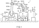
- FIG. 1 and FIG. 2 the configuration of the picking system of this embodiment is shown.
- FIG. 1 is a schematic view of a picking system 1.
- FIG. 2 is a block diagram of the picking system 1.
- the picking system 1 is configured to include a picking robot 11 and distance detecting device 12.
- the picking robot 11 is a robot configured to carry out picking of an article 2 and is configured to include a robot arm 3 and arm control section 4.
- the distance detecting device 12 is a device configured to acquire and analyze the data of a distance from itself to an object 21 including the article 2 picked by the picking robot 11 and is configured to include a distance detector 5 and detector control section 6.
- the picking robot 11 and distance detecting device 12 respectively have separate configurations, these configurations may also be integrated.
- the robot arm 3 carries out picking of the articles 2 collected in the collection area 20 and moves the picked article 2 from the collection area 20 to a desired area (hereinafter referred to as a move destination area).
- the article 2 is a concrete object which can be an object of picking such as baggage including a home-delivered article, package, postal matter, and the like, various parts, products, and the like. A case where the figures (sizes, shapes, weight values, packed states, and the like) of the article 2 are not uniform and diversified is assumed.
- the robot arm 3 is configured to include a base stand section 31, arm section 32, and end effector 33.
- the base stand section 31 is installed on an installation surface 7.
- the base stand section 31 is positioned and fixed on a floor surface identical to that of the collection area 20 by using the floor surface as the installation surface 7.
- the base stand section 31 may also be made movable on the floor surface without being positioned and fixed as described above.
- a configuration in which the base stand section 31 is supported in such a manner that the base stand section 31 can be slid along a guide rail laid on the floor surface can also be employed. Thereby, it becomes possible to move the robot arm 3 with respect to the floor surface.
- the arm section 32 extends from the base end section that is a part at which the arm section 32 is connected to the base stand section 31 to the top in such a manner that arm members are coupled to each other by means of a plurality of articulation sections 34.
- the arm section 32 is divided into a plurality of arm members by the articulation sections 34.
- the parts 32a to 32e are coupled to each other in sequence from the base stand section 31 by the predetermined articulation sections 34a to 34e and are respectively made rotatable around predetermined axes 35a to 35g.
- the five parts 32a to 32e are coupled to each other by means of the five articulation sections 34a to 34e and respectively rotate around the seven axes 35a to 35g.
- the configuration of the arm section 32 is not limited to this.
- the end effector 33 is detachably attached to the apical end (arm apical end section 36) of the arm section 32 and is made rotatable around the axis 35g together with the part (fifth part) 32e of the arm section 32. Further, the end effector 33 is configured to be attachable/detachable to/from the arm apical end section 36 and various types different from each other in size, shape, and the like are applied according to the articles 2 to be picked. The detailed configuration of the end effector 33 will be described later.
- the arm section 32 and end effector 33 are rotated around the axes 35a to 35g by means of control motors (illustration omitted). Thereby, the arm section 32 is made to assume a desired posture with respect to the base stand section 31 and is freely displaced (operated) within a predetermined range. In the predetermined range (i.e., range of movement), the collection area 20 of the articles 2 and move destination area are included. Accordingly, by making the arm section 32 and end effector 33 rotate around the axes 35a to 35g, it becomes possible to displace these members with respect to the collection area 20 and move destination area.
- the robot arm 3 is not limited to the configuration in which the robot arm 3 is controlled to operate around the seven axes 35a to 35g as in the case of this embodiment, and a configuration in which the robot arm 3 is controlled to operate around six or less axes or around eight or more axes may also be employed.
- the arm control section 4 controls the robot arm 3.
- the arm control section 4 is configured to include, for example, a CPU, memory, input/output circuit, timer, and the like.
- the arm control section 4 reads various data items by means of the input/output circuit, carries out a mathematical operation by means of the CPU by using a program read from the memory, and carries out control based on a result of the mathematical operation.
- the arm control section 4 is connected to the robot arm 3 including the end effector 33 by wire or wirelessly and transmits/receives various data items, results of mathematical operations, and the like to/from these members.
- the arm control section 4 reads, for example, detection data of the collection state of the article group 2s in the collection area 20 by means of the input/output circuit, carries out a mathematical operation by means of the CPU by using a program read from the memory, and controls the operations of the robot arm 3 and end effector 33 on the basis of a result of the mathematical operation.
- the arm control section 4 has a configuration independent of the detector control section 6, these members 4 and 6 may also have an integrated configuration.
- the distance detector 5 detects (measures) a distance from itself to each of the members of the object 21 including the article 2 picked by the robot arm 3.
- light is applied as a detection medium of the distance detector 5. Accordingly, the distance detector 5 radiates incident light 50 toward the object 21 and measures the distance from itself to the object 21 on the basis of the time elapsed from radiation of the incident light 50 to reception of light reflected from the object 21.
- the object 21 is a physical body capable of receiving incident light 50 from the distance detector 5 and includes the end effector 33 (gripping mechanism 8 to be described later), to-be-detected section 9 (to be described later), and air in addition to the picked article 2.
- a laser range finder LRF configured to oscillate and radiate laser light, and perceive the laser light bouncing back from the object 21 is applied as an example.
- the laser light serving as the incident light 50 is infrared laser light
- the incident light 50 is laser light such as visible light, ultraviolet light, X-ray, and the like.
- the distance detector 5 detects (measures) a distance from itself to the object 21 on a movement locus of the article 2 picked by the robot arm 3 to be obtained after the robot arm 3 has carried out picking of the article 2.
- the distance detector 5 is fixed at an arbitrary position (position P1 shown in FIG. 1 as an example, and referred to as a reference position P1 hereinafter) at which the object 21 passing through any position on the aforementioned movement locus and laser light radiation perceiving section 51 can be opposed to each other. That is, the distance detector 5 detects the distance from itself to the object 21 at such timing that the object 21 just passes through a distance detection position (as an example, position P2 shown in FIG. 1 referred to as a distance detection position P2 hereinafter) which is a definite point on the movement locus.
- a distance detection position as an example, position P2 shown in FIG. 1 referred to as a distance detection position P2 hereinafter
- the distance detector 5 radiates the incident light 50 throughout a predetermined length on a straight line intersecting the direction of movement of the object 21.
- the distance detector 5 linearly radiates the incident light 50 in one direction on the horizontal plane perpendicular to the direction of movement (vertical direction) of the object 21. Then, the object 21 is moved along the movement locus, whereby the distance detector 5 carries out planar scanning (distance detection) of the surface of the object 21 throughout a predetermined range.
- the distance detector 5 is positioned to and fixed at the reference position P1 and, in this state, the object 21 is moved, the distance from the distance detector 5 to the object 21 may also be detected by moving the distance detector 5 and immobilizing the object 21. Alternatively, both the distance detector 5 and object 21 may be moved. Then, the distance detector 5 detects the distance from itself to the object 21 on the basis of the optical characteristics of the reflected light corresponding to the radiated incident light 50.
- the detector control section 6 controls the distance detector 5.
- the detector control section 6 is configured to include, for example, a CPU, memory, input/output circuit, timer, and the like.
- the detector control section 6 reads various data items by means of the input/output circuit, carries out a mathematical operation by means of the CPU by using a program read from the memory, and carries out control based on a result of the mathematical operation.
- the detector control section 6 is connected to the distance detector 5 by wire or wirelessly and transmits/receives various data items, results of mathematical operations, and the like to/from the distance detector 5.
- the detector control section 6 operates the distance detector 5 and, at the same time, classifies the detection values detected by the distance detector 5 into a detection value group of the article 2 and detection value groups of members other than the article 2 on the basis of a detection value group of the to-be-detected sections 9 to be described later.
- the detection value group is a time-series aggregate of detection values acquired within a predetermined detection time.
- the detector control section 6 is configured to include a data analysis section 61 and data estimation section 62.
- the data analysis section 61 and data estimation section 62 are stored in a memory as, for example, programs.
- the detector control section 6 reads a detection value (distance data) of the distance detector 5 by means of the input/output circuit, carries out a mathematical operation by means of the CPU by using the programs (data analysis section and data estimation section) read from the memory, and executes an analysis and estimation of the detection value to be described later on the basis of a result of the mathematical operation.
- the data analysis section 61 analyzes the detection values detected by the distance detector 5 and classifies the detection values into a plurality of detection value groups.
- the detection value is a value of data of the distance from the distance detector 5 to the object 21.
- the data analysis section 61 classifies distance data items into a plurality of distance data groups according to presence/absence of time-series consecutiveness (hereinafter referred to as continuity of detection values) of the detection values detected by the distance detector 5.
- the data analysis section 61 determines that the detection values have no continuity when the variation in the detection value detected by the distance detector 5 is a variation a variation range of which lies astride a predetermined threshold (hereinafter referred to as a reference value). That is, the data analysis section 61 classifies (divides) the detection value group before and after the detection value exceeds the reference value. Alternatively, the data analysis section 61 determines that there is no continuity when the variation in the detection value detected by the distance detector 5 is a variation exceeding a predetermined coefficient of variation (hereinafter referred to as a reference variation coefficient). That is, the data analysis section 61 classifies (divides) the detection value group before and after the coefficient of variation of the detection value exceeds the reference variation coefficient.
- a predetermined threshold hereinafter referred to as a reference value
- the coefficient of variation of the detection value is an index indicating a ratio of the variation in the current detection value to the immediately preceding detection value.
- the coefficient of variation and reference variation coefficient are set in advance according to the optical characteristics of the to-be-detected section 9 to be described later and are stored in a storage device (nonvolatile memory). These values are read by the data analysis section 61 as analysis parameters when the detection values are classified into a plurality of detection value groups.
- the data estimation section 62 estimates a detection value group of the article 2 from the plurality of detection value groups on the basis of the classification determined by the data analysis section 61. In other words, the data estimation section 62 classifies the detection value groups into the detection value group of the article 2 and detection value groups of the members of the object 21 other than the article 2 by estimation.
- the article 2 in this case is an article 2 (as an example, article 2a shown in FIG. 1 ) actually being picked by the robot arm.
- the detection value group is an aggregate (distance data group) of data items of distances from the distance detector to the object 21. That is, the data estimation section 62 estimates a distance data group indicating the article 2 within the range (search range) of matching with the master data according to such classification.
- the master data is a reference detection value group (reference distance data group) achieved by previously acquiring the distance data to be obtained when the distance from the distance detector 5 fixed at the reference position P1 to the article 2 is detected by the distance detector 5 at the time when the picked article 2 passes through the distance detection position P2 on the movement locus for all the articles 2 included in the article group 2s of the collection area 20.
- reference detection value group reference distance data group
- the end effector has the following configuration. As shown in FIG. 1 , the end effector 33 is configured to include a gripping mechanism 8 and to-be-detected section 9.
- the griping mechanism 8 grips the article 2 in a releasable manner. Gripping is specified as a concept comprehending the whole of holding modes of the article 2 such as suction-attraction, pinching or the like.
- the end effector 33 carries out suction (suction-attraction) and release of the article 2 by means of air.
- the gripping mechanism 8 is configured to include a base section, suction-attracting section, vacuum generator, compressor, electromagnetic valve, pressure sensor (their illustrations omitted), and the like.
- the base section is attached to the arm apical end section 36 of the robot arm 3.
- the suction-attracting section is arranged on the side of the base section opposite to the side at which the base section is attached to the arm apical end section 36, suction-attracts the article 2 by being internally evacuated by the vacuum generator, and releases the article 2 by being internally vacuum-broken (by being opened to the atmosphere).
- the vacuum generator is connected to the compressor through the electromagnetic valve and carries out suction/blowing of air from/into the inside of the suction-attracting section.
- the electromagnetic valve controls the suction and blowing of air to be carried out by the vacuum generator by opening/closing of the valve.
- the pressure sensor is provided between the suction-attracting section and vacuum generator and measures the internal pressure (adsorption pressure of the article 2) of the suction-attracting section. Operations of all the vacuum generator, compressor, electromagnetic valve, and pressure sensor are controlled by control signals received from the arm control section 4.
- the to-be-detected section 9 is one of the members of the object 21 to be irradiated with the incident light 50 from the distance detector 5 and, in short, is one of the members of the object 21 which is a distance detection (measurement) object of the distance detector 5 and is arranged at the boundary between the article 2 and gripping mechanism 8 or in the vicinity of the boundary.
- the detection value group indicating the detection result of the distance from the distance detector 5 to the to-be-detected section 9 to be detected by the distance detector 5 has optical characteristics different from the detection value group indicating the distance from the distance detector 5 to the article 2 to be detected by the distance detector 5.
- optical characteristic is one of a far distance (infinity), absorption, and variation.
- the detection value group of the to-be-detected section 9 becomes values indicating one of the optical characteristics of infinity, absorption, and variation.
- the optical characteristic for example, a case where the reflectance of the reflected light of, for example, the incident light (laser light) 50 at the to-be-detected section 9 is extremely high or is extremely low in comparison with the reflectance of the reflected light of the incident light (laser light) 50 at the article 2, case where the variation period of the reflectance is short, case where the range of variation in the reflectance is large, and the like can be mentioned.
- the case corresponds to the to-be-detected section 9 having optical characteristics in which the reflectance is extremely high.
- the case corresponds to the to-be-detected section 9 having optical characteristics in which the reflectance is extremely low. It is sufficient if these upper limit and lower limit are set in such a manner that these values can easily be distinguished from the reflectance of the reflected light at the article 2 according to the above reflectance.
- the to-be-detected section 9 may be any type of member, so long as the member has such optical characteristics and is constituted of, for example, a mirror, blackbody, member a surface shape of which differs from the surface shape of the article 2 (hereinafter referred to as an atypical body) or the like.
- the atypical body is, for example, a member or the like the surface of which forms a convex/concave shape on a predetermined cycle.
- reflection of the incident light (laser light) 50 at the mirror resembles the radiation toward the sky, and hence the detection value group of the distance to the mirror approximates to a value indicative of a far distance which corresponds to the detection value group of the sky.
- the detection value group of the distance detected by the distance detector 5 becomes a value indicative of absorption (abnormal value making distance detection impossible).
- the incident light (laser light) 50 from the distance detector 5 is hardly reflected and is absorbed by the to-be-detected section 9, and hence distance detection is made impossible.
- the detection value group of the distance detected by the distance detector 5 becomes, for example, a value indicative of a variation of a short period or value having a large range of variation.
- to-be-detected sections 9 is selected and applied according to the figure of the article 2 included in the article group 2s.
- an article the surface color (including wrapping color and painting color) of which is black is included in the article group 2s, not a blackbody but a mirror or atypical body is applied as the to-be-detected section 9.
- an article the surface shape (including the surface shape or the like of the wrapping paper) of which is a convex/concave shape is included in the article group 2s, not an atypical body but a mirror or blackbody is applied as the to-be-detected section 9.
- the robot arm 3 carries out picking of the article 2 (article 2a in FIG. 1 ) from the collection area 20.
- the arm control section 4 makes the arm section 32 of the robot arm 3 operate to grip the article 2 (S101).
- the end effector 33 is operation-controlled by the arm control section 4, and the gripping mechanism 8 suction-attracts the article 2.
- an article 2 to be suction-attracted by the gripping mechanism 8 is selected from the article group 2s collected in the collection area 20.
- the arm control section 4 causes the arm section 32 to operate to make the gripping mechanism 8 (suction-attracting section) descend toward the selected article 2, makes the vacuum generator, compressor, and electromagnetic valve operate, and makes the suction-attracting section suction-attract the article 2.
- the arm control section 4 After making the gripping mechanism 8 (suction-attracting section) suction-attract the article 2, the arm control section 4 makes the arm section 32 operate in such a manner that each of the members of the object 21 including the article 2 passes through the distance detection position P2 (S102).
- the arm section 32 lifts the article 2 from the collection area 20 in the vertical direction to a predetermined height.
- the distance detection position P2 is set at an arbitrary position above the collection area 20 and equal to or lower than a predetermined height (see FIG. 1 ).
- Whether or not the article 2 has been suction-attracted by the gripping mechanism is determined by the arm control section 4 on the basis of, for example, the internal pressure (adsorption pressure of the article 2) of the suction-attracting section measured by the pressure sensor.
- the detector control section 6 makes the distance detector 5 operate to detect (measure) the distance from the distance detector 5 to each of the members of the object 21 including the article 2 (S103).
- the members of the object 21 pass (upwardly) through the distance detection position P2 in the order of the gripping mechanism 8, to-be-detected section 9, article 2, and air.
- the distance detector 5 measures the distance from itself to each of the gripping mechanism 8, to-be-detected section 9, article 2, and air in the order mentioned.
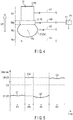
- FIG. 4 an example of a distance data detection mode adopted by the distance detector 5 is shown.
- the distance detector 5 acquires the distance data in the order of the area R1, area RM, area R2, and area R3.
- the area R1, area RM, area R2, and area R3 respectively correspond to the incident light (laser light)-reception areas in the gripping mechanism 8, to-be-detected section 9, article 2 (2a), and air.
- the to-be-detected section 9 a mirror is applied as an example.
- the laser light emitted from the distance detector 5 is reflected in the area R1 as indicated by the arrow A1, is reflected in the area RM as indicated by the arrow AM, is reflected in the area R2 as indicated by the arrow A2, and is reflected in the area R3 as indicated by the arrow A3.
- the distance detector 5 acquires distance data in each of the areas R1, RM, R2, and R3 on the basis of the reflection modes of the laser light indicated by the arrows A1, AM, A2, and A3.
- the detector control section 6 analyzes the distance data.
- the data analysis section 61 analyzes the distance data (detection value detected by the distance detector 5) to classify (divide) the distance data into a plurality of distance data groups (S104).
- FIG. 5 an acquired result (time transition of distance data) of distance data at the distance detector 5 corresponding to the reflection modes of the laser light shown in FIG. 4 is shown.
- the distance data in each of the areas R1, RM, R2, and R3 has time-series consecutiveness, i.e., continuity.
- the continuity is cut off. That is, between the area R1 and area RM, the distance data value abruptly increases from D1 to DM to exceed a reference value DX. Further, between the area RM and area R2, the distance data value abruptly lowers from DM to D2 to become less than the reference value DX.
- the distance data value abruptly increases from D2 to D3 to exceed the reference value DX.
- the distance data values D1, DM, D2, and D3 are respectively the representative values in the areas R1, RM, R2, and R3, and the distance data in each area is a value in the vicinity of each representative value.
- the data analysis section 61 classifies (divides) the distance data acquired by the distance detector 5 into distance data groups G1, GM, G2, and G3 in the areas R1, RM, R2, and R3 according to the variation mode based on the reference value DX. It should be noted that, in this case, the data analysis section 61 may classify the distance data according to the variation mode based on the reference variation coefficient.
- the detector control section 6 estimates the distance data group of the article 2 (2a) from these distance data groups G1, GM, G2, and G3 (S105).
- the data estimation section 62 classifies (divides) the distance data into the distance data group G2 of the article 2a and distance data groups G1, GM, and G3 of the members of the object 21 other than the article 2a.
- the distance data obtained by the distance detector 5 is acquired in the order of the area R1, area RM, area R2, and area R3, and the distance data of the article 2a corresponds to the area R2.
- the data estimation section 62 estimates, from among the distance data groups, the distance data group G2 of the area R2 interposed between the distance data groups GM and G3 of the area RM and area R3, and is separated from these distance data groups GM and G3 to be the distance data group indicating the article 2a. That is, thereby, the distance data group G2 of the area R2 is estimated to be the distance data group indicating the article 2a being within the range of matching with the master data.
- the data estimation section 62 Upon completion of the estimation of the distance data group indicating the article 2a, the data estimation section 62 terminates the estimation processing. Then, for example, when the article 2a which has been gripped is released, and another article 2 is picked from the collection area 20, the arm control section 4 and detector control section 6 carry out the control from S101 to S105 again.
- the end effector 33 of the robot arm 3 is provided with the to-be-detected section 9, and hence the following effect is exhibited as compared with the comparative example shown in FIG. 6 .
- FIG. 6 the configuration of an end effector 33a of a robot arm 3 according to a comparative example, and state where an article 2 (2a) is suction-attracted by the end effector 33a are shown.
- the end effector 33a of the comparative example is not provided with a to-be-detected section (see FIG. 4 ).
- the other configurations in the comparative example excluding the to-be-detected section 9 are identical to this embodiment. Accordingly, the configurations identical to this embodiment ( FIG. 4 ) are denoted by reference symbols identical to this embodiment on the drawing.
- the distance detector 5 detects (measures) the distances from itself to the gripping mechanism 8, article 2a, and air in the order named.
- the distance detector 5 acquires distance data in the order of the area R1 (gripping mechanism 8), area R2 (article 2a), and area R3 (air).
- FIG. 7 an acquired result (time transition of distance data) of the distance data at the distance detector 5 corresponding to the reflection modes of the laser light shown in FIG. 6 is shown.
- the distance data in each of the areas R1, R2, and R3 has time-series consecutiveness, i.e., continuity.
- the continuity is cut off.
- the distance data between the area R1 and area R2 has time-series consecutiveness, i.e., continuity although slight variation is found therein.
- the distance data obtained by the distance detector 5 is acquired in the order of the area R1, area R2, and area R3, and the distance data of the article 2a corresponds to the area R2.
- the to-be-detected section 9 is not provided, and hence the distance data value does not abruptly increase to exceed the reference value DX between the area R1 and area R2, and the continuity of the distance data between these areas is not cut off.
- the distance data acquired by the distance detector 5 is only classified into the distance data group G12 in the areas R1 and R2, and distance data group G3 in the area R3. That is, it is not possible to classify the distance data into the distance data groups G1, G2, and G3 in the areas R1, R2, and R3. As a result, it is not possible to classify (divide) the distance data into the distance data group indicating the article 2 and distance data group indicating the members of the object 21 other than the article 2.
- the end effector 33 is provided with the to-be-detected section 9 as described above, and hence it is possible to interpose the distance data group GM in the area RM (to-be-detected section 9) between the distance data group G1 in the area R1 (gripping mechanism 8) and distance data group G2 in the area R2 (article 2a). Thereby, it is possible to cut off the continuity of the distance data between the area R1 and area R2.
- the distance data group (as an example, the distance data group G2 indicating the article 2a) indicating the article 2 is estimated, and hence it is possible to narrow down the matching range (search range).
- search range search range
- the distance data group indicating the article 2 is estimated. Accordingly, by analyzing such a distance data group, it is possible to estimate the shape and size of the picked article 2 (as an example, article 2a shown in FIG. 1 ). Accordingly, for example, when the picked article 2 is released, it becomes possible to release the article 2 at a most appropriate place or height on the basis of the estimated shape and size. Thereby, it is possible to attempt prevention of breakage or the like of the article 2 at the time of release.
- the to-be-detected section 9 may also be a blackbody or atypical body.
- a blackbody is applied will be described below as a first modification example ( FIG. 8 and FIG. 9 )
- an atypical body is applied will be described below as a second modification example ( FIG. 10 and FIG. 11 ).
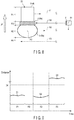
- FIG. 8 an example of a detection mode of distance data carried out by the distance detector 5 of a case where the to-be-detected section 9a is made a blackbody is shown.
- FIG. 9 an acquired result of distance data at the distance detector 5 corresponding to the reflection modes of the laser light shown in FIG. 8 is shown.
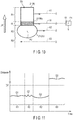
- FIG. 10 an example of a detection mode of distance data of a case where the to-be-detected section 9a is made an atypical body.
- FIG. 11 an acquired result of distance data corresponding to the reflection modes of the laser light shown in FIG. 10 is shown.
- the laser light radiated from the distance detector 5 is not reflected in the area RB (blackbody) as indicated by the arrow AB and is almost totally absorbed. Accordingly, the distance data in the area RB becomes an abnormal value (approximately zero) making distance detection impossible. In this case, the distance data value abruptly decreases to become less than the reference value DX between the area R1 and area R2, and hence it is possible to cut off the continuity of the distance data between these areas. Thereby, it is possible to separate the distance data group G2 of the area R2 (article 2a) and distance data group G1 of the area R1 (gripping mechanism 8) from each other.
- the laser light radiated from the distance detector 5 is reflect in the area R1 (atypical body) as indicated by the arrow AI. Accordingly, the distance data value in the area R1 becomes a value finely varying with a fixed period. In this case, the distance data value does not abruptly vary between values above and below the reference value DX at a part between the area R1 and area R2 and continuity of the distance data between these areas is not cut off. However, the distance data group GI in the area R1 (atypical body) is detected in the mode obviously different from the distance data group G2 in the area R2 (article 2a).
- the distance data group GI of the area RI is interposed between the area R1 and area R2, whereby it possible to separate the distance data group G2 of the area R2 (article 2a) and distance data group G1 of the area R1 (gripping mechanism 8) from each other.
- first modification example, and second modification example which are described above, although the end effectors 33 (gripping mechanism 8) are respectively provided with the to-be-detected sections 9, 9a, and 9b, in place of providing these sections, for example, the surface of the gripping mechanism 8 (base section, suction-attracting section, and the like) may be mirrored or the surface thereof may also be painted black. In this case, the mirrored part or black-painted part corresponds to the to-be-detected section.
- the gripping mechanism 8 of the end effector 33 is made a suction-attracting mechanism
- the gripping mechanism 8 may also be made a pinching mechanism configured to carry out pinching and release of the article 2 by means of, for example, a plurality of fingers (claws).
- a plurality of fingers claws
- the distances to the members of the object 21 including the article 2 are detected (measured) and the distance data is classified into a plurality of distance data groups.
- the surface shapes of the members of the object 21 may be detected from, for example, the distance data and the data of the surface shapes may be classified into a plurality of surface shape data groups.
Landscapes
- Engineering & Computer Science (AREA)
- Robotics (AREA)
- Mechanical Engineering (AREA)
- Physics & Mathematics (AREA)
- Optics & Photonics (AREA)
- Human Computer Interaction (AREA)
- Health & Medical Sciences (AREA)
- General Health & Medical Sciences (AREA)
- Orthopedic Medicine & Surgery (AREA)
- General Physics & Mathematics (AREA)
- Manipulator (AREA)
- Length Measuring Devices By Optical Means (AREA)
Abstract
Description
- Embodiments described herein relate generally to a picking system configured to carry out picking of an article by means of various manipulators (robot arms) and end effector of a robot arm to be used in the picking system.
- A robot arm is provided with an end effector corresponding to the use application or service at an arm apical end section thereof. The end effector includes, as a mechanism (gripping mechanism) configured to grip an article at the time of picking, a suction-attracting mechanism or the like configured to carry out suction-attraction and release of an article by means of, for example, air. It should be noted that gripping is a concept comprehending the whole of holding modes of articles including not only suction-attraction but also pinching or the like. Accordingly, the gripping mechanism is sometimes configured as a pinching mechanism or the like configured to carry out pinching and release of an article by means of a plurality of fingers (claws).
- For example, when an article is picked up from a collection area and is moved to a desired area, the article which is the object of picking is selected on the basis of the collection modes of the article group detected by an article detecting section such as a camera or sensor. The selected article (hereinafter referred to as a selected article) is gripped by the end effector of the robot arm and is moved from the collection area to the desired area.
-
- Patent Literature 1:
JP 2011-212818 A - Patent Literature 2:
JP 2012-051080 A - Patent Literature 3:
JP 2009-056513 A - Here, when the article group includes a wide variety of articles, various articles are gripped by the end effector. Further, there is a possibility of an article (hereinafter referred to as a gripped article) actually gripped being different from the selected article.
- For this reason, in a step subsequent to the step in which the article has been gripped, estimation of the gripped article is carried out in order to move the gripped article to an appropriate place or release the article at an appropriate height. In order to estimate the gripped article, for example, a surface shape, size or the like of the gripped article is detected, and the detection data is compared (matched) with the master data of the articles included in the article group. The master data is an aggregate of data items obtained by previously detecting surface shapes, sizes and the like of the articles included in the article group. Accordingly, in order to quickly and efficiently carry out estimation of the gripped article, it is expedient that the matching range (search range) in which the detection data and master data are matched with each other be narrower.
- Thus, a picking system and end effector of a robot arm which make it possible to narrow down the matching range of the detection data at the time of estimation of a gripped article are provided.
- An end effector of an embodiment comprises: a gripping mechanism attached to an arm apical end section of a robot arm configured to carry out picking of an article, and configured to grip the article in a releasable manner; and a to-be-detected section arranged at a boundary between the article and the gripping mechanism or in the vicinity of the boundary and is irradiated with incident light from a distance detector configured to detect a distance from itself to an object on the basis of optical characteristics of reflected light corresponding to the irradiated incident light, wherein regarding the to-be-detected section, a detection value group indicating a detection result of a distance from the distance detector to the to-be-detected section to be detected by the distance detector possesses optical characteristics different from a detection value group indicating a distance from the distance detector to the article to be detected by the distance detector.
-
-
FIG. 1 is a schematic view showing the configuration of a picking system of an embodiment. -
FIG. 2 is a block diagram showing the configuration of the picking system of the embodiment. -
FIG. 3 is a control flow chart of an arm control section and detector control section in the picking system of the embodiment. -
FIG. 4 is a schematic view showing the configuration of an end effector in the picking system of the embodiment and example of a mode of detection of distance data carried out by a distance detector. -
FIG. 5 is a view showing an acquired result (time transition of distance data value) of distance data at the distance detector corresponding to the reflection modes of incident light (laser light) shown inFIG. 4 in the picking system of the embodiment. -
FIG. 6 is a schematic view showing the configuration of an end effector in the picking system of a comparative example and example of a mode of detection of distance data carried out by a distance detector. -
FIG. 7 is a view showing an acquired result (time transition of distance data value) of distance data at the distance detector corresponding to the reflection modes of incident light (laser light) shown inFIG. 6 in the picking system of the comparative example. -
FIG. 8 is a schematic view showing the configuration of an end effector in the picking system of a first modification example of the embodiment and mode of detection of distance data carried out by a distance detector. -
FIG. 9 is a view showing an acquired result (time transition of distance data value) of distance data at the distance detector corresponding to the reflection modes of incident light (laser light) shown inFIG. 8 in the picking system of the first modification example. -
FIG. 10 is a schematic view showing the configuration of an end effector in the picking system of a second modification example of the embodiment and mode of detection of distance data carried out by a distance detector. -
FIG. 11 is a view showing an acquired result (time transition of distance data value) of distance data at the distance detector corresponding to the reflection modes of incident light (laser light) shown inFIG. 10 in the picking system of the second modification example. - Mode for Carrying Out the Invention Hereinafter an article picking system of an embodiment and end effector of a manipulator (hereinafter referred to as a robot arm) to be used in the picking system will be described with reference to
FIGS. 1 to 11 . - In
FIG. 1 andFIG. 2 , the configuration of the picking system of this embodiment is shown.FIG. 1 is a schematic view of apicking system 1.FIG. 2 is a block diagram of thepicking system 1. As shown inFIG. 1 andFIG. 2 , thepicking system 1 is configured to include a pickingrobot 11 anddistance detecting device 12. The pickingrobot 11 is a robot configured to carry out picking of anarticle 2 and is configured to include arobot arm 3 andarm control section 4. Thedistance detecting device 12 is a device configured to acquire and analyze the data of a distance from itself to anobject 21 including thearticle 2 picked by the pickingrobot 11 and is configured to include adistance detector 5 anddetector control section 6. In this embodiment, although the pickingrobot 11 anddistance detecting device 12 respectively have separate configurations, these configurations may also be integrated. - The
robot arm 3 carries out picking of thearticles 2 collected in thecollection area 20 and moves the pickedarticle 2 from thecollection area 20 to a desired area (hereinafter referred to as a move destination area). Thearticle 2 is a concrete object which can be an object of picking such as baggage including a home-delivered article, package, postal matter, and the like, various parts, products, and the like. A case where the figures (sizes, shapes, weight values, packed states, and the like) of thearticle 2 are not uniform and diversified is assumed. - As shown in
FIG. 1 , therobot arm 3 is configured to include abase stand section 31,arm section 32, andend effector 33. - The
base stand section 31 is installed on aninstallation surface 7. In this embodiment, thebase stand section 31 is positioned and fixed on a floor surface identical to that of thecollection area 20 by using the floor surface as theinstallation surface 7. It should be noted that thebase stand section 31 may also be made movable on the floor surface without being positioned and fixed as described above. For example, a configuration in which thebase stand section 31 is supported in such a manner that thebase stand section 31 can be slid along a guide rail laid on the floor surface can also be employed. Thereby, it becomes possible to move therobot arm 3 with respect to the floor surface. - The
arm section 32 extends from the base end section that is a part at which thearm section 32 is connected to thebase stand section 31 to the top in such a manner that arm members are coupled to each other by means of a plurality ofarticulation sections 34. Thearm section 32 is divided into a plurality of arm members by thearticulation sections 34. Theparts 32a to 32e are coupled to each other in sequence from thebase stand section 31 by thepredetermined articulation sections 34a to 34e and are respectively made rotatable aroundpredetermined axes 35a to 35g. In this embodiment, in thearm section 32, the fiveparts 32a to 32e are coupled to each other by means of the fivearticulation sections 34a to 34e and respectively rotate around the sevenaxes 35a to 35g. However, the configuration of thearm section 32 is not limited to this. - The
end effector 33 is detachably attached to the apical end (arm apical end section 36) of thearm section 32 and is made rotatable around theaxis 35g together with the part (fifth part) 32e of thearm section 32. Further, theend effector 33 is configured to be attachable/detachable to/from the armapical end section 36 and various types different from each other in size, shape, and the like are applied according to thearticles 2 to be picked. The detailed configuration of theend effector 33 will be described later. - The
arm section 32 andend effector 33 are rotated around theaxes 35a to 35g by means of control motors (illustration omitted). Thereby, thearm section 32 is made to assume a desired posture with respect to thebase stand section 31 and is freely displaced (operated) within a predetermined range. In the predetermined range (i.e., range of movement), thecollection area 20 of thearticles 2 and move destination area are included. Accordingly, by making thearm section 32 andend effector 33 rotate around theaxes 35a to 35g, it becomes possible to displace these members with respect to thecollection area 20 and move destination area. - It should be noted that the
robot arm 3 is not limited to the configuration in which therobot arm 3 is controlled to operate around the sevenaxes 35a to 35g as in the case of this embodiment, and a configuration in which therobot arm 3 is controlled to operate around six or less axes or around eight or more axes may also be employed. - The
arm control section 4 controls therobot arm 3. Thearm control section 4 is configured to include, for example, a CPU, memory, input/output circuit, timer, and the like. Thearm control section 4 reads various data items by means of the input/output circuit, carries out a mathematical operation by means of the CPU by using a program read from the memory, and carries out control based on a result of the mathematical operation. In this embodiment, thearm control section 4 is connected to therobot arm 3 including theend effector 33 by wire or wirelessly and transmits/receives various data items, results of mathematical operations, and the like to/from these members. Thereby, thearm control section 4 reads, for example, detection data of the collection state of thearticle group 2s in thecollection area 20 by means of the input/output circuit, carries out a mathematical operation by means of the CPU by using a program read from the memory, and controls the operations of therobot arm 3 and endeffector 33 on the basis of a result of the mathematical operation. It should be noted that in this embodiment, although thearm control section 4 has a configuration independent of thedetector control section 6, thesemembers - The
distance detector 5 detects (measures) a distance from itself to each of the members of theobject 21 including thearticle 2 picked by therobot arm 3. In this embodiment, light is applied as a detection medium of thedistance detector 5. Accordingly, thedistance detector 5 radiates incident light 50 toward theobject 21 and measures the distance from itself to theobject 21 on the basis of the time elapsed from radiation of the incident light 50 to reception of light reflected from theobject 21. - The
object 21 is a physical body capable of receiving incident light 50 from thedistance detector 5 and includes the end effector 33 (grippingmechanism 8 to be described later), to-be-detected section 9 (to be described later), and air in addition to the pickedarticle 2. As thedistance detector 5, a laser range finder (LRF) configured to oscillate and radiate laser light, and perceive the laser light bouncing back from theobject 21 is applied as an example. Although it is sufficient if the laser light serving as theincident light 50 is infrared laser light, it is also sufficient if theincident light 50 is laser light such as visible light, ultraviolet light, X-ray, and the like. - The
distance detector 5 detects (measures) a distance from itself to theobject 21 on a movement locus of thearticle 2 picked by therobot arm 3 to be obtained after therobot arm 3 has carried out picking of thearticle 2. In this embodiment, as an example, thedistance detector 5 is fixed at an arbitrary position (position P1 shown inFIG. 1 as an example, and referred to as a reference position P1 hereinafter) at which theobject 21 passing through any position on the aforementioned movement locus and laser lightradiation perceiving section 51 can be opposed to each other. That is, thedistance detector 5 detects the distance from itself to theobject 21 at such timing that theobject 21 just passes through a distance detection position (as an example, position P2 shown inFIG. 1 referred to as a distance detection position P2 hereinafter) which is a definite point on the movement locus. - At that time, the
distance detector 5 radiates theincident light 50 throughout a predetermined length on a straight line intersecting the direction of movement of theobject 21. In this embodiment, as an example, thedistance detector 5 linearly radiates the incident light 50 in one direction on the horizontal plane perpendicular to the direction of movement (vertical direction) of theobject 21. Then, theobject 21 is moved along the movement locus, whereby thedistance detector 5 carries out planar scanning (distance detection) of the surface of theobject 21 throughout a predetermined range. As described above, in this embodiment, although thedistance detector 5 is positioned to and fixed at the reference position P1 and, in this state, theobject 21 is moved, the distance from thedistance detector 5 to theobject 21 may also be detected by moving thedistance detector 5 and immobilizing theobject 21. Alternatively, both thedistance detector 5 and object 21 may be moved. Then, thedistance detector 5 detects the distance from itself to theobject 21 on the basis of the optical characteristics of the reflected light corresponding to the radiatedincident light 50. - The
detector control section 6 controls thedistance detector 5. Thedetector control section 6 is configured to include, for example, a CPU, memory, input/output circuit, timer, and the like. Thedetector control section 6 reads various data items by means of the input/output circuit, carries out a mathematical operation by means of the CPU by using a program read from the memory, and carries out control based on a result of the mathematical operation. In this embodiment, thedetector control section 6 is connected to thedistance detector 5 by wire or wirelessly and transmits/receives various data items, results of mathematical operations, and the like to/from thedistance detector 5. - The
detector control section 6 operates thedistance detector 5 and, at the same time, classifies the detection values detected by thedistance detector 5 into a detection value group of thearticle 2 and detection value groups of members other than thearticle 2 on the basis of a detection value group of the to-be-detected sections 9 to be described later. The detection value group is a time-series aggregate of detection values acquired within a predetermined detection time. In order to execute such processing, thedetector control section 6 is configured to include adata analysis section 61 anddata estimation section 62. Thedata analysis section 61 anddata estimation section 62 are stored in a memory as, for example, programs. In this embodiment, thedetector control section 6 reads a detection value (distance data) of thedistance detector 5 by means of the input/output circuit, carries out a mathematical operation by means of the CPU by using the programs (data analysis section and data estimation section) read from the memory, and executes an analysis and estimation of the detection value to be described later on the basis of a result of the mathematical operation. - The
data analysis section 61 analyzes the detection values detected by thedistance detector 5 and classifies the detection values into a plurality of detection value groups. The detection value is a value of data of the distance from thedistance detector 5 to theobject 21. For example, thedata analysis section 61 classifies distance data items into a plurality of distance data groups according to presence/absence of time-series consecutiveness (hereinafter referred to as continuity of detection values) of the detection values detected by thedistance detector 5. - When carrying out such classification, the
data analysis section 61 determines that the detection values have no continuity when the variation in the detection value detected by thedistance detector 5 is a variation a variation range of which lies astride a predetermined threshold (hereinafter referred to as a reference value). That is, thedata analysis section 61 classifies (divides) the detection value group before and after the detection value exceeds the reference value. Alternatively, thedata analysis section 61 determines that there is no continuity when the variation in the detection value detected by thedistance detector 5 is a variation exceeding a predetermined coefficient of variation (hereinafter referred to as a reference variation coefficient). That is, thedata analysis section 61 classifies (divides) the detection value group before and after the coefficient of variation of the detection value exceeds the reference variation coefficient. The coefficient of variation of the detection value is an index indicating a ratio of the variation in the current detection value to the immediately preceding detection value. The coefficient of variation and reference variation coefficient are set in advance according to the optical characteristics of the to-be-detected section 9 to be described later and are stored in a storage device (nonvolatile memory). These values are read by thedata analysis section 61 as analysis parameters when the detection values are classified into a plurality of detection value groups. - The
data estimation section 62 estimates a detection value group of thearticle 2 from the plurality of detection value groups on the basis of the classification determined by thedata analysis section 61. In other words, thedata estimation section 62 classifies the detection value groups into the detection value group of thearticle 2 and detection value groups of the members of theobject 21 other than thearticle 2 by estimation. Thearticle 2 in this case is an article 2 (as an example,article 2a shown inFIG. 1 ) actually being picked by the robot arm. The detection value group is an aggregate (distance data group) of data items of distances from the distance detector to theobject 21. That is, thedata estimation section 62 estimates a distance data group indicating thearticle 2 within the range (search range) of matching with the master data according to such classification. The master data is a reference detection value group (reference distance data group) achieved by previously acquiring the distance data to be obtained when the distance from thedistance detector 5 fixed at the reference position P1 to thearticle 2 is detected by thedistance detector 5 at the time when the pickedarticle 2 passes through the distance detection position P2 on the movement locus for all thearticles 2 included in thearticle group 2s of thecollection area 20. It should be noted that in this embodiment, although it is assumed that thedata estimation section 62 does not carry out matching of the detection value group with the master data, it is also possible for thedata estimation section 62 to carry out the matching. - In order to facilitate classification of distance data items to be carried out by the
data analysis section 61 and estimation of a distance data group indicating thearticle 2 to be carried out by thedata estimation section 62, the end effector has the following configuration. As shown inFIG. 1 , theend effector 33 is configured to include agripping mechanism 8 and to-be-detected section 9. - The
griping mechanism 8 grips thearticle 2 in a releasable manner. Gripping is specified as a concept comprehending the whole of holding modes of thearticle 2 such as suction-attraction, pinching or the like. In this embodiment, as an example, theend effector 33 carries out suction (suction-attraction) and release of thearticle 2 by means of air. Accordingly, thegripping mechanism 8 is configured to include a base section, suction-attracting section, vacuum generator, compressor, electromagnetic valve, pressure sensor (their illustrations omitted), and the like. The base section is attached to the armapical end section 36 of therobot arm 3. The suction-attracting section is arranged on the side of the base section opposite to the side at which the base section is attached to the armapical end section 36, suction-attracts thearticle 2 by being internally evacuated by the vacuum generator, and releases thearticle 2 by being internally vacuum-broken (by being opened to the atmosphere). The vacuum generator is connected to the compressor through the electromagnetic valve and carries out suction/blowing of air from/into the inside of the suction-attracting section. The electromagnetic valve controls the suction and blowing of air to be carried out by the vacuum generator by opening/closing of the valve. The pressure sensor is provided between the suction-attracting section and vacuum generator and measures the internal pressure (adsorption pressure of the article 2) of the suction-attracting section. Operations of all the vacuum generator, compressor, electromagnetic valve, and pressure sensor are controlled by control signals received from thearm control section 4. - The to-
be-detected section 9 is one of the members of theobject 21 to be irradiated with the incident light 50 from thedistance detector 5 and, in short, is one of the members of theobject 21 which is a distance detection (measurement) object of thedistance detector 5 and is arranged at the boundary between thearticle 2 andgripping mechanism 8 or in the vicinity of the boundary. Regarding the to-be-detected section 9, the detection value group indicating the detection result of the distance from thedistance detector 5 to the to-be-detected section 9 to be detected by thedistance detector 5 has optical characteristics different from the detection value group indicating the distance from thedistance detector 5 to thearticle 2 to be detected by thedistance detector 5. In such optical characteristics, both of an optical characteristic which can be detected by thedistance detector 5 and optical characteristic which cannot be detected (in other words, an abnormal value is detected) by thedistance detector 5 are included. For example, the optical characteristic is one of a far distance (infinity), absorption, and variation. In this case, the detection value group of the to-be-detected section 9 becomes values indicating one of the optical characteristics of infinity, absorption, and variation. Further, regarding the optical characteristic, for example, a case where the reflectance of the reflected light of, for example, the incident light (laser light) 50 at the to-be-detected section 9 is extremely high or is extremely low in comparison with the reflectance of the reflected light of the incident light (laser light) 50 at thearticle 2, case where the variation period of the reflectance is short, case where the range of variation in the reflectance is large, and the like can be mentioned. For example, when there is a case where the reflectance of the reflected light is higher than a predetermined upper limit, the case corresponds to the to-be-detected section 9 having optical characteristics in which the reflectance is extremely high. Further, when there is a case where the reflectance of the reflected light is lower than a predetermined lower limit, the case corresponds to the to-be-detected section 9 having optical characteristics in which the reflectance is extremely low. It is sufficient if these upper limit and lower limit are set in such a manner that these values can easily be distinguished from the reflectance of the reflected light at thearticle 2 according to the above reflectance. - The to-
be-detected section 9 may be any type of member, so long as the member has such optical characteristics and is constituted of, for example, a mirror, blackbody, member a surface shape of which differs from the surface shape of the article 2 (hereinafter referred to as an atypical body) or the like. The atypical body is, for example, a member or the like the surface of which forms a convex/concave shape on a predetermined cycle. When the to-be-detected section 9 is made a mirror, the detection value group of the distance detected by thedistance detector 5 approximates to a value indicative of a far distance. In this case, reflection of the incident light (laser light) 50 at the mirror resembles the radiation toward the sky, and hence the detection value group of the distance to the mirror approximates to a value indicative of a far distance which corresponds to the detection value group of the sky. When the to-be-detected section 9 is made a blackbody, the detection value group of the distance detected by thedistance detector 5 becomes a value indicative of absorption (abnormal value making distance detection impossible). In this case, the incident light (laser light) 50 from thedistance detector 5 is hardly reflected and is absorbed by the to-be-detected section 9, and hence distance detection is made impossible. That is, a state where the amount of light is saturated or state where the reflected light of the incident light (laser light) 50 from thedistance detector 5 cannot be obtained is brought about, and the obtained value becomes a non-numeric value. When the to-be-detected section is made an atypical body, the detection value group of the distance detected by thedistance detector 5 becomes, for example, a value indicative of a variation of a short period or value having a large range of variation. - It is sufficient if one of these types of to-
be-detected sections 9 is selected and applied according to the figure of thearticle 2 included in thearticle group 2s. For example, when an article the surface color (including wrapping color and painting color) of which is black is included in thearticle group 2s, not a blackbody but a mirror or atypical body is applied as the to-be-detected section 9. Alternatively, when an article the surface shape (including the surface shape or the like of the wrapping paper) of which is a convex/concave shape is included in thearticle group 2s, not an atypical body but a mirror or blackbody is applied as the to-be-detected section 9. - The operations and functions of the
robot arm 3 anddistance detector 5 at the time of detection of the distance from thedistance detector 5 to the object 21 (grippingmechanism 8, to-be-detected section 9,article 2, and air) to be carried out by thedistance detector 5 will be described below according to the control flows of thearm control section 4 anddetector control section 6. InFIG. 3 , a control flow of thearm control section 4 for therobot arm 3, and control flow of thedetector control section 6 for thedistance detector 5 are shown, i.e., estimation processing of the distance data group indicating thearticle 2 is shown. - First, the
robot arm 3 carries out picking of the article 2 (article 2a inFIG. 1 ) from thecollection area 20. For this purpose, thearm control section 4 makes thearm section 32 of therobot arm 3 operate to grip the article 2 (S101). In this embodiment, theend effector 33 is operation-controlled by thearm control section 4, and thegripping mechanism 8 suction-attracts thearticle 2. At that time, anarticle 2 to be suction-attracted by the gripping mechanism 8 (suction-attracting section) is selected from thearticle group 2s collected in thecollection area 20. Then, thearm control section 4 causes thearm section 32 to operate to make the gripping mechanism 8 (suction-attracting section) descend toward the selectedarticle 2, makes the vacuum generator, compressor, and electromagnetic valve operate, and makes the suction-attracting section suction-attract thearticle 2. - After making the gripping mechanism 8 (suction-attracting section) suction-attract the
article 2, thearm control section 4 makes thearm section 32 operate in such a manner that each of the members of theobject 21 including thearticle 2 passes through the distance detection position P2 (S102). In this embodiment, as an example, thearm section 32 lifts thearticle 2 from thecollection area 20 in the vertical direction to a predetermined height. In this case, the distance detection position P2 is set at an arbitrary position above thecollection area 20 and equal to or lower than a predetermined height (seeFIG. 1 ). Whether or not thearticle 2 has been suction-attracted by the gripping mechanism (suction-attracting section) is determined by thearm control section 4 on the basis of, for example, the internal pressure (adsorption pressure of the article 2) of the suction-attracting section measured by the pressure sensor. - When the
object 21 passes through the distance detection position P2, thedetector control section 6 makes thedistance detector 5 operate to detect (measure) the distance from thedistance detector 5 to each of the members of theobject 21 including the article 2 (S103). In this case, the members of theobject 21 pass (upwardly) through the distance detection position P2 in the order of thegripping mechanism 8, to-be-detected section 9,article 2, and air. Accordingly, thedistance detector 5 measures the distance from itself to each of thegripping mechanism 8, to-be-detected section 9,article 2, and air in the order mentioned. - In
FIG. 4 , an example of a distance data detection mode adopted by thedistance detector 5 is shown. In this case, thedistance detector 5 acquires the distance data in the order of the area R1, area RM, area R2, and area R3. The area R1, area RM, area R2, and area R3 respectively correspond to the incident light (laser light)-reception areas in thegripping mechanism 8, to-be-detected section 9, article 2 (2a), and air. It should be noted that as the to-be-detected section 9, a mirror is applied as an example. When each of the members of theobject 21 including thearticle 2a ascends as indicated by the arrow UP, the laser light emitted from thedistance detector 5 is reflected in the area R1 as indicated by the arrow A1, is reflected in the area RM as indicated by the arrow AM, is reflected in the area R2 as indicated by the arrow A2, and is reflected in the area R3 as indicated by the arrow A3. Thedistance detector 5 acquires distance data in each of the areas R1, RM, R2, and R3 on the basis of the reflection modes of the laser light indicated by the arrows A1, AM, A2, and A3. - After the distance data acquisition by the
distance detector 5, thedetector control section 6 analyzes the distance data. In this embodiment, thedata analysis section 61 analyzes the distance data (detection value detected by the distance detector 5) to classify (divide) the distance data into a plurality of distance data groups (S104). - In
FIG. 5 , an acquired result (time transition of distance data) of distance data at thedistance detector 5 corresponding to the reflection modes of the laser light shown inFIG. 4 is shown. As shown inFIG. 5 , the distance data in each of the areas R1, RM, R2, and R3 has time-series consecutiveness, i.e., continuity. Conversely, in the distance data between areas, the continuity is cut off. That is, between the area R1 and area RM, the distance data value abruptly increases from D1 to DM to exceed a reference value DX. Further, between the area RM and area R2, the distance data value abruptly lowers from DM to D2 to become less than the reference value DX. Further, between the area R2 and area R3, the distance data value abruptly increases from D2 to D3 to exceed the reference value DX. It should be noted that the distance data values D1, DM, D2, and D3 are respectively the representative values in the areas R1, RM, R2, and R3, and the distance data in each area is a value in the vicinity of each representative value. - Accordingly, the
data analysis section 61 classifies (divides) the distance data acquired by thedistance detector 5 into distance data groups G1, GM, G2, and G3 in the areas R1, RM, R2, and R3 according to the variation mode based on the reference value DX. It should be noted that, in this case, thedata analysis section 61 may classify the distance data according to the variation mode based on the reference variation coefficient. - After the distance data is classified by the
data analysis section 61 into the distance data groups G1, GM, G2, and G3, thedetector control section 6 estimates the distance data group of the article 2 (2a) from these distance data groups G1, GM, G2, and G3 (S105). In this embodiment, as an example, thedata estimation section 62 classifies (divides) the distance data into the distance data group G2 of thearticle 2a and distance data groups G1, GM, and G3 of the members of theobject 21 other than thearticle 2a. The distance data obtained by thedistance detector 5 is acquired in the order of the area R1, area RM, area R2, and area R3, and the distance data of thearticle 2a corresponds to the area R2. Accordingly, thedata estimation section 62 estimates, from among the distance data groups, the distance data group G2 of the area R2 interposed between the distance data groups GM and G3 of the area RM and area R3, and is separated from these distance data groups GM and G3 to be the distance data group indicating thearticle 2a. That is, thereby, the distance data group G2 of the area R2 is estimated to be the distance data group indicating thearticle 2a being within the range of matching with the master data. - Upon completion of the estimation of the distance data group indicating the
article 2a, thedata estimation section 62 terminates the estimation processing. Then, for example, when thearticle 2a which has been gripped is released, and anotherarticle 2 is picked from thecollection area 20, thearm control section 4 anddetector control section 6 carry out the control from S101 to S105 again. - As described above, according to the
picking system 1 of this embodiment, theend effector 33 of therobot arm 3 is provided with the to-be-detected section 9, and hence the following effect is exhibited as compared with the comparative example shown inFIG. 6 . - In
FIG. 6 , the configuration of anend effector 33a of arobot arm 3 according to a comparative example, and state where an article 2 (2a) is suction-attracted by theend effector 33a are shown. As shown inFIG. 6 , theend effector 33a of the comparative example is not provided with a to-be-detected section (seeFIG. 4 ). However, the other configurations in the comparative example excluding the to-be-detected section 9 are identical to this embodiment. Accordingly, the configurations identical to this embodiment (FIG. 4 ) are denoted by reference symbols identical to this embodiment on the drawing. - In the comparative example, the
distance detector 5 detects (measures) the distances from itself to thegripping mechanism 8,article 2a, and air in the order named. In the detection mode of distance data shown inFIG. 6 , thedistance detector 5 acquires distance data in the order of the area R1 (gripping mechanism 8), area R2 (article 2a), and area R3 (air). InFIG. 7 , an acquired result (time transition of distance data) of the distance data at thedistance detector 5 corresponding to the reflection modes of the laser light shown inFIG. 6 is shown. As shown inFIG. 7 , the distance data in each of the areas R1, R2, and R3 has time-series consecutiveness, i.e., continuity. Further, in the distance data between the area R2 and area R3, the continuity is cut off. However, the distance data between the area R1 and area R2 has time-series consecutiveness, i.e., continuity although slight variation is found therein. - In the comparative example too, as in the case of this embodiment described above, the distance data obtained by the
distance detector 5 is acquired in the order of the area R1, area R2, and area R3, and the distance data of thearticle 2a corresponds to the area R2. However, in the comparative example, the to-be-detected section 9 is not provided, and hence the distance data value does not abruptly increase to exceed the reference value DX between the area R1 and area R2, and the continuity of the distance data between these areas is not cut off. - Accordingly, the distance data acquired by the
distance detector 5 is only classified into the distance data group G12 in the areas R1 and R2, and distance data group G3 in the area R3. That is, it is not possible to classify the distance data into the distance data groups G1, G2, and G3 in the areas R1, R2, and R3. As a result, it is not possible to classify (divide) the distance data into the distance data group indicating thearticle 2 and distance data group indicating the members of theobject 21 other than thearticle 2. - Conversely, in this embodiment, the
end effector 33 is provided with the to-be-detected section 9 as described above, and hence it is possible to interpose the distance data group GM in the area RM (to-be-detected section 9) between the distance data group G1 in the area R1 (gripping mechanism 8) and distance data group G2 in the area R2 (article 2a). Thereby, it is possible to cut off the continuity of the distance data between the area R1 and area R2. - Therefore, according to this embodiment, it is possible to classify (divide) the distance data into the distance data group indicating the
article 2 and distance data groups indicating the members of theobject 21 other than thearticle 2. Thereby, for example, in the subsequent step, when the distance data is compared (matched) with the master data, the distance data group (as an example, the distance data group G2 indicating thearticle 2a) indicating thearticle 2 is estimated, and hence it is possible to narrow down the matching range (search range). As a result of this narrowing, it is possible to carry out matching more quickly and more efficiently and, by extension, it becomes possible to carry out estimation (specification) of thearticle 2 more quickly and more efficiently. - In this embodiment, matching is not carried out, and hence although the
article 2 is not specified, the distance data group indicating thearticle 2 is estimated. Accordingly, by analyzing such a distance data group, it is possible to estimate the shape and size of the picked article 2 (as an example,article 2a shown inFIG. 1 ). Accordingly, for example, when the pickedarticle 2 is released, it becomes possible to release thearticle 2 at a most appropriate place or height on the basis of the estimated shape and size. Thereby, it is possible to attempt prevention of breakage or the like of thearticle 2 at the time of release. - While certain embodiments have been described, these embodiments have been presented by way of example only, and are not intended to limit the scope of the inventions. Indeed, the novel embodiments described herein may be embodied in a variety of other forms; furthermore, various omissions, substitutions and changes in the form of the embodiments described herein may be made without departing from the spirit of the inventions. The accompanying claims and their equivalents are intended to cover such forms or modifications as would fall within the scope and spirit of the inventions.
- In this embodiment, although a mirror is applied as the to-
be-detected section 9, as described above, the to-be-detected section 9 may also be a blackbody or atypical body. Hereinafter, an embodiment in which a blackbody is applied will be described below as a first modification example (FIG. 8 and FIG. 9 ), and embodiment in which an atypical body is applied will be described below as a second modification example (FIG. 10 and FIG. 11 ). - In
FIG. 8 , an example of a detection mode of distance data carried out by thedistance detector 5 of a case where the to-be-detected section 9a is made a blackbody is shown. InFIG. 9 , an acquired result of distance data at thedistance detector 5 corresponding to the reflection modes of the laser light shown inFIG. 8 is shown. Likewise, inFIG. 10 , an example of a detection mode of distance data of a case where the to-be-detected section 9a is made an atypical body. InFIG. 11 , an acquired result of distance data corresponding to the reflection modes of the laser light shown inFIG. 10 is shown. It should be noted that the other configurations excluding the to-be-detected sections FIG. 4 ) are denoted by reference symbols identical to this embodiment on the drawing. - As shown in
FIG. 8 and FIG. 9 , when the to-be-detected section 9a is made a blackbody, the laser light radiated from thedistance detector 5 is not reflected in the area RB (blackbody) as indicated by the arrow AB and is almost totally absorbed. Accordingly, the distance data in the area RB becomes an abnormal value (approximately zero) making distance detection impossible. In this case, the distance data value abruptly decreases to become less than the reference value DX between the area R1 and area R2, and hence it is possible to cut off the continuity of the distance data between these areas. Thereby, it is possible to separate the distance data group G2 of the area R2 (article 2a) and distance data group G1 of the area R1 (gripping mechanism 8) from each other. - Further, as shown in
FIG. 10 and FIG. 11 , when the to-be-detected section 9b is made an atypical body, the laser light radiated from thedistance detector 5 is reflect in the area R1 (atypical body) as indicated by the arrow AI. Accordingly, the distance data value in the area R1 becomes a value finely varying with a fixed period. In this case, the distance data value does not abruptly vary between values above and below the reference value DX at a part between the area R1 and area R2 and continuity of the distance data between these areas is not cut off. However, the distance data group GI in the area R1 (atypical body) is detected in the mode obviously different from the distance data group G2 in the area R2 (article 2a). Accordingly, the distance data group GI of the area RI is interposed between the area R1 and area R2, whereby it possible to separate the distance data group G2 of the area R2 (article 2a) and distance data group G1 of the area R1 (gripping mechanism 8) from each other. - It should be noted that in this embodiment, first modification example, and second modification example which are described above, although the end effectors 33 (gripping mechanism 8) are respectively provided with the to-
be-detected sections - Further, in this embodiment, first modification example, and second modification example which are described above, although the
gripping mechanism 8 of theend effector 33 is made a suction-attracting mechanism, thegripping mechanism 8 may also be made a pinching mechanism configured to carry out pinching and release of thearticle 2 by means of, for example, a plurality of fingers (claws). In this case, it is sufficient if a mirror, blackbody, atypical body or the like is arranged in the vicinity of each of tips of the fingers (claws) as the to-be-detected section. - It should be noted that in this embodiment, first modification example, and second modification example which are described above, the distances to the members of the
object 21 including thearticle 2 are detected (measured) and the distance data is classified into a plurality of distance data groups. In place of the above, the surface shapes of the members of theobject 21 may be detected from, for example, the distance data and the data of the surface shapes may be classified into a plurality of surface shape data groups. -
- 1 ...
- Picking system
- 2, 2a ...
- Article
- 2s ...
- Article group
- 3 ...
- Robot arm
- 4 ...
- Arm control section
- 5 ...
- Distance detector
- 6 ...
- Detector control section
- 7 ...
- Installation surface
- 8 ...
- Gripping mechanism
- 9, 9a, 9b ...
- To-be-detected section
- 11 ...
- Picking robot
- 12 ...
- Distance detecting device
- 20 ...
- Collection area
- 21 ...
- Object
- 31 ...
- Base stand section
- 32 (32a to 32e) ...
- Arm section
- 33, 33a ...
- End effector
- 34 (34a to 34e) ...
- Articulation section
- 35a to 35g ...
- Axes
- 36 ...
- Arm apical end section
- 50 ...
- Incident light (laser light)
- 51 ...
- Laser light radiation perceiving section
- 61 ...
- Data analysis section
- 62 ...
- Data estimation section
- D1, D2, D3, DM ...
- Distance data values
- DX ...
- Reference value
- G1, G2, G3, G12, GI, GM ...
- Distance data group
- P1 ...
- Reference position
- P2 ...
- Distance detection position
Claims (10)
- An end effector of a robot arm comprising:a gripping mechanism attached to an arm apical end section of the robot arm configured to carry out picking of an article, and configured to grip the article in a releasable manner; anda to-be-detected section arranged at a boundary between the article and the gripping mechanism or in the vicinity of the boundary and is irradiated with incident light from a distance detector configured to detect a distance from itself to an object on the basis of optical characteristics of reflected light corresponding to the irradiated incident light, whereinregarding the to-be-detected section, a detection value group indicating a detection result of a distance from the distance detector to the to-be-detected section to be detected by the distance detector possesses optical characteristics different from a detection value group indicating a distance from the distance detector to the article to be detected by the distance detector.
- The end effector of the robot arm of claim 1, wherein
the detection value group of the to-be-detected section is values indicating one of optical characteristics of a far distance, absorption, and variation. - The end effector of the robot arm of claim 1, wherein
the to-be-detected section is one of a mirror, a blackbody, and a member a surface shape of which differs from a surface shape of the article. - A picking system comprising:a robot arm configured to carry out picking of an article by means of an end effector attached to an arm apical end section thereof;an arm control section configured to control an operation of the robot arm;a distance detector configured to detect each of distances from the distance detector to members of an object including the article on the basis of optical characteristics of reflected light corresponding to irradiated incident light on a movement locus of the article picked by the robot arm to be obtained after the robot arm has carried out picking of the article; anda detector control section configured to control an operation of the distance detector, whereinthe end effector includesa gripping mechanism configured to grip the article in a releasable manner, anda to-be-detected section arranged at a boundary between the article and the gripping mechanism or in the vicinity of the boundary and is irradiated with the incident light from the distance detector,regarding the to-be-detected section, a detection value group indicating a detection result of a distance from the distance detector to the to-be-detected section to be detected by the distance detector possesses optical characteristics different from a detection value group indicating a distance from the distance detector to the article to be detected by the distance detector, andthe detector control section classifies detection values detected by the distance detector into a detection value group of the article and detection value groups of members of the object other than the article on the basis of a detection value group of the to-be-detected section.
- The picking system of claim 4, wherein
the detector control section includes
a data analysis section configured to analyze the detection values and classify the detection values into a plurality of detection value groups, and
a data estimation section configured to estimate a detection value group of the article from the plurality of detection value groups on the basis of the classification carried out by the data analysis section. - The picking system of claim 5, wherein
the data analysis section classifies the detection values into the plurality of detection value groups according to presence/absence of continuity of the detection values. - The picking system of claim 6, wherein
the data analysis section determines that there is no continuity when a range of the variation in the detection value lies astride a predetermined threshold. - The picking system of claim 6, wherein
the data analysis section determines that there is no continuity when the variation in the detection value is a variation exceeding a predetermined coefficient of variation. - The picking system of claim 4, wherein
the distance detector is a laser range finder configured to oscillate laser light, radiate the laser light toward the object, and perceive the laser light bouncing back from the object. - The picking system of claim 9, wherein
the to-be-detected section possesses the optical characteristics in which a reflectance of reflected light of the laser light radiated from the laser range finder at the to-be-detected section is higher than a predetermined upper limit or is lower than a predetermined lower limit in comparison with a reflectance of reflected light of the laser light at the article.
Applications Claiming Priority (2)
| Application Number | Priority Date | Filing Date | Title |
|---|---|---|---|
| JP2018047141A JP2019155549A (en) | 2018-03-14 | 2018-03-14 | Picking system and end effector for robot arm |
| PCT/JP2018/040118 WO2019176158A1 (en) | 2018-03-14 | 2018-10-29 | Picking system and end effector for robot arm |
Publications (2)
| Publication Number | Publication Date |
|---|---|
| EP3738727A1 true EP3738727A1 (en) | 2020-11-18 |
| EP3738727A4 EP3738727A4 (en) | 2021-10-06 |
Family
ID=67906558
Family Applications (1)
| Application Number | Title | Priority Date | Filing Date |
|---|---|---|---|
| EP18909936.9A Withdrawn EP3738727A4 (en) | 2018-03-14 | 2018-10-29 | Picking system and end effector for robot arm |
Country Status (4)
| Country | Link |
|---|---|
| US (1) | US20200391379A1 (en) |
| EP (1) | EP3738727A4 (en) |
| JP (1) | JP2019155549A (en) |
| WO (1) | WO2019176158A1 (en) |
Families Citing this family (3)
| Publication number | Priority date | Publication date | Assignee | Title |
|---|---|---|---|---|
| NO345105B1 (en) * | 2019-03-18 | 2020-09-28 | Macgregor Norway As | Multiaxial robotic arm |
| CN114310863A (en) * | 2020-09-29 | 2022-04-12 | 艾卡(南通)智能科技有限公司 | Modularized robot execution tool |
| US12129132B2 (en) * | 2021-03-15 | 2024-10-29 | Dexterity, Inc. | Singulation of arbitrary mixed items |
Family Cites Families (16)
| Publication number | Priority date | Publication date | Assignee | Title |
|---|---|---|---|---|
| JPH07290388A (en) * | 1994-04-22 | 1995-11-07 | Suzuki Motor Corp | Chuck jig |
| US5802201A (en) * | 1996-02-09 | 1998-09-01 | The Trustees Of Columbia University In The City Of New York | Robot system with vision apparatus and transparent grippers |
| JP2001277167A (en) * | 2000-03-31 | 2001-10-09 | Okayama Pref Gov Shin Gijutsu Shinko Zaidan | 3D pose recognition method |
| JP2005231789A (en) * | 2004-02-18 | 2005-09-02 | Fuji Photo Film Co Ltd | Pancake changing robot |
| JP4575727B2 (en) * | 2004-08-23 | 2010-11-04 | 川崎重工業株式会社 | Substrate state detection device, robot hand, and substrate transfer robot |
| JP4759491B2 (en) * | 2006-11-01 | 2011-08-31 | 株式会社ミツトヨ | manipulator |
| JP2009056513A (en) | 2007-08-29 | 2009-03-19 | Toshiba Corp | Gripping position / posture determination system and gripping position / posture determination method |
| JP5702975B2 (en) * | 2010-03-31 | 2015-04-15 | 株式会社ダイヘン | Substrate transfer robot |
| JP2011212818A (en) | 2010-04-01 | 2011-10-27 | Toyota Motor Corp | Environment recognition robot |
| JP5561037B2 (en) | 2010-09-02 | 2014-07-30 | トヨタ自動車株式会社 | Robot and control method thereof |
| JP5685027B2 (en) * | 2010-09-07 | 2015-03-18 | キヤノン株式会社 | Information processing apparatus, object gripping system, robot system, information processing method, object gripping method, and program |
| JP5852364B2 (en) * | 2011-08-26 | 2016-02-03 | キヤノン株式会社 | Information processing apparatus, information processing apparatus control method, and program |
| US9393686B1 (en) * | 2013-03-15 | 2016-07-19 | Industrial Perception, Inc. | Moveable apparatuses having robotic manipulators and conveyors to facilitate object movement |
| JP6415026B2 (en) * | 2013-06-28 | 2018-10-31 | キヤノン株式会社 | Interference determination apparatus, interference determination method, and computer program |
| US9272417B2 (en) * | 2014-07-16 | 2016-03-01 | Google Inc. | Real-time determination of object metrics for trajectory planning |
| ES2929729T3 (en) * | 2015-11-13 | 2022-12-01 | Berkshire Grey Operating Company Inc | Classification systems to provide classification of a variety of objects |
-
2018
- 2018-03-14 JP JP2018047141A patent/JP2019155549A/en active Pending
- 2018-10-29 EP EP18909936.9A patent/EP3738727A4/en not_active Withdrawn
- 2018-10-29 WO PCT/JP2018/040118 patent/WO2019176158A1/en not_active Ceased
-
2020
- 2020-09-01 US US17/009,035 patent/US20200391379A1/en not_active Abandoned
Also Published As
| Publication number | Publication date |
|---|---|
| JP2019155549A (en) | 2019-09-19 |
| WO2019176158A1 (en) | 2019-09-19 |
| EP3738727A4 (en) | 2021-10-06 |
| US20200391379A1 (en) | 2020-12-17 |
Similar Documents
| Publication | Publication Date | Title |
|---|---|---|
| US20200391379A1 (en) | Picking system and end effector of robot arm | |
| CN113825598B (en) | Object gripping system and method | |
| US10603791B2 (en) | Apparatus, method for controlling apparatus, and storage medium | |
| US9694499B2 (en) | Article pickup apparatus for picking up randomly piled articles | |
| EP3453493A2 (en) | Article movement apparatus, article movement method, and article movement control program | |
| KR102040996B1 (en) | Robotic arm | |
| CN110741976B (en) | Egg sorting equipment | |
| US10773435B2 (en) | Injection molding system | |
| CN106808472B (en) | Location of workpiece posture computing device and handling system | |
| EP3852682B1 (en) | Leaflet-testing apparatus | |
| JP6981765B2 (en) | Goods transfer device | |
| KR20140092378A (en) | System and method for processing samples | |
| WO2015056649A1 (en) | System for automating specimen inspection, capacity checking module, and method for checking biological sample | |
| US20190346465A1 (en) | Transport device, sample measurement system, and transport method | |
| US20200254627A1 (en) | Holding mechanism, transfer device, handling robot system, and robot handling method | |
| EP4011509A2 (en) | Method, apparatus, and computer program product for automatically performing sorting operations | |
| US20180313861A1 (en) | Transporting apparatus, transporting method, and sample analysis system | |
| Mu et al. | Design of end-effector for kiwifruit harvesting robot experiment | |
| US10978333B2 (en) | Systems and methods for robotic arm sensing | |
| JP2017162133A (en) | Imaging system, measurement system, production system, imaging method, program, recording medium, and measurement method | |
| JP4890998B2 (en) | Sample processing system | |
| JP6516727B2 (en) | Sample test automation system and check module and sample check method | |
| EP3822202A1 (en) | Picking system, information processing device, and computer-readable recording medium | |
| JP2001105378A (en) | Handling device | |
| CN104704374B (en) | Analytical system with capillary transport mechanism |
Legal Events
| Date | Code | Title | Description |
|---|---|---|---|
| STAA | Information on the status of an ep patent application or granted ep patent |
Free format text: STATUS: THE INTERNATIONAL PUBLICATION HAS BEEN MADE |
|
| PUAI | Public reference made under article 153(3) epc to a published international application that has entered the european phase |
Free format text: ORIGINAL CODE: 0009012 |
|
| STAA | Information on the status of an ep patent application or granted ep patent |
Free format text: STATUS: REQUEST FOR EXAMINATION WAS MADE |
|
| 17P | Request for examination filed |
Effective date: 20200812 |
|
| AK | Designated contracting states |
Kind code of ref document: A1 Designated state(s): AL AT BE BG CH CY CZ DE DK EE ES FI FR GB GR HR HU IE IS IT LI LT LU LV MC MK MT NL NO PL PT RO RS SE SI SK SM TR |
|
| AX | Request for extension of the european patent |
Extension state: BA ME |
|
| DAV | Request for validation of the european patent (deleted) | ||
| DAX | Request for extension of the european patent (deleted) | ||
| A4 | Supplementary search report drawn up and despatched |
Effective date: 20210908 |
|
| RIC1 | Information provided on ipc code assigned before grant |
Ipc: B25J 15/00 20060101ALI20210902BHEP Ipc: G01B 11/02 20060101ALI20210902BHEP Ipc: B25J 9/16 20060101ALI20210902BHEP Ipc: G01B 11/24 20060101ALI20210902BHEP Ipc: G01B 11/00 20060101ALI20210902BHEP Ipc: B25J 19/02 20060101ALI20210902BHEP Ipc: B25J 13/08 20060101AFI20210902BHEP |
|
| STAA | Information on the status of an ep patent application or granted ep patent |
Free format text: STATUS: EXAMINATION IS IN PROGRESS |
|
| 17Q | First examination report despatched |
Effective date: 20240115 |
|
| STAA | Information on the status of an ep patent application or granted ep patent |
Free format text: STATUS: THE APPLICATION HAS BEEN WITHDRAWN |
|
| 18W | Application withdrawn |
Effective date: 20240429 |