EP3738666A1 - Slurry production apparatus - Google Patents
Slurry production apparatus Download PDFInfo
- Publication number
- EP3738666A1 EP3738666A1 EP19215892.1A EP19215892A EP3738666A1 EP 3738666 A1 EP3738666 A1 EP 3738666A1 EP 19215892 A EP19215892 A EP 19215892A EP 3738666 A1 EP3738666 A1 EP 3738666A1
- Authority
- EP
- European Patent Office
- Prior art keywords
- powder
- dew point
- point temperature
- dry
- slurry
- Prior art date
- Legal status (The legal status is an assumption and is not a legal conclusion. Google has not performed a legal analysis and makes no representation as to the accuracy of the status listed.)
- Pending
Links
Images


Classifications
-
- H—ELECTRICITY
- H01—ELECTRIC ELEMENTS
- H01M—PROCESSES OR MEANS, e.g. BATTERIES, FOR THE DIRECT CONVERSION OF CHEMICAL ENERGY INTO ELECTRICAL ENERGY
- H01M4/00—Electrodes
- H01M4/02—Electrodes composed of, or comprising, active material
- H01M4/13—Electrodes for accumulators with non-aqueous electrolyte, e.g. for lithium-accumulators; Processes of manufacture thereof
- H01M4/139—Processes of manufacture
-
- B—PERFORMING OPERATIONS; TRANSPORTING
- B01—PHYSICAL OR CHEMICAL PROCESSES OR APPARATUS IN GENERAL
- B01F—MIXING, e.g. DISSOLVING, EMULSIFYING OR DISPERSING
- B01F33/00—Other mixers; Mixing plants; Combinations of mixers
- B01F33/80—Mixing plants; Combinations of mixers
- B01F33/82—Combinations of dissimilar mixers
- B01F33/821—Combinations of dissimilar mixers with consecutive receptacles
-
- B—PERFORMING OPERATIONS; TRANSPORTING
- B01—PHYSICAL OR CHEMICAL PROCESSES OR APPARATUS IN GENERAL
- B01F—MIXING, e.g. DISSOLVING, EMULSIFYING OR DISPERSING
- B01F23/00—Mixing according to the phases to be mixed, e.g. dispersing or emulsifying
- B01F23/70—Pre-treatment of the materials to be mixed
- B01F23/704—Drying materials, e.g. in order to mix them in solid state
-
- B—PERFORMING OPERATIONS; TRANSPORTING
- B01—PHYSICAL OR CHEMICAL PROCESSES OR APPARATUS IN GENERAL
- B01F—MIXING, e.g. DISSOLVING, EMULSIFYING OR DISPERSING
- B01F23/00—Mixing according to the phases to be mixed, e.g. dispersing or emulsifying
- B01F23/50—Mixing liquids with solids
-
- B—PERFORMING OPERATIONS; TRANSPORTING
- B01—PHYSICAL OR CHEMICAL PROCESSES OR APPARATUS IN GENERAL
- B01F—MIXING, e.g. DISSOLVING, EMULSIFYING OR DISPERSING
- B01F23/00—Mixing according to the phases to be mixed, e.g. dispersing or emulsifying
- B01F23/50—Mixing liquids with solids
- B01F23/53—Mixing liquids with solids using driven stirrers
-
- B—PERFORMING OPERATIONS; TRANSPORTING
- B01—PHYSICAL OR CHEMICAL PROCESSES OR APPARATUS IN GENERAL
- B01F—MIXING, e.g. DISSOLVING, EMULSIFYING OR DISPERSING
- B01F23/00—Mixing according to the phases to be mixed, e.g. dispersing or emulsifying
- B01F23/50—Mixing liquids with solids
- B01F23/565—Mixing liquids with solids by introducing liquids in solid material, e.g. to obtain slurries
-
- B—PERFORMING OPERATIONS; TRANSPORTING
- B01—PHYSICAL OR CHEMICAL PROCESSES OR APPARATUS IN GENERAL
- B01F—MIXING, e.g. DISSOLVING, EMULSIFYING OR DISPERSING
- B01F23/00—Mixing according to the phases to be mixed, e.g. dispersing or emulsifying
- B01F23/50—Mixing liquids with solids
- B01F23/59—Mixing systems, i.e. flow charts or diagrams
-
- B—PERFORMING OPERATIONS; TRANSPORTING
- B01—PHYSICAL OR CHEMICAL PROCESSES OR APPARATUS IN GENERAL
- B01F—MIXING, e.g. DISSOLVING, EMULSIFYING OR DISPERSING
- B01F25/00—Flow mixers; Mixers for falling materials, e.g. solid particles
- B01F25/50—Circulation mixers, e.g. wherein at least part of the mixture is discharged from and reintroduced into a receptacle
- B01F25/53—Circulation mixers, e.g. wherein at least part of the mixture is discharged from and reintroduced into a receptacle in which the mixture is discharged from and reintroduced into a receptacle through a recirculation tube, into which an additional component is introduced
-
- B—PERFORMING OPERATIONS; TRANSPORTING
- B01—PHYSICAL OR CHEMICAL PROCESSES OR APPARATUS IN GENERAL
- B01F—MIXING, e.g. DISSOLVING, EMULSIFYING OR DISPERSING
- B01F25/00—Flow mixers; Mixers for falling materials, e.g. solid particles
- B01F25/60—Pump mixers, i.e. mixing within a pump
- B01F25/64—Pump mixers, i.e. mixing within a pump of the centrifugal-pump type, i.e. turbo-mixers
-
- B—PERFORMING OPERATIONS; TRANSPORTING
- B01—PHYSICAL OR CHEMICAL PROCESSES OR APPARATUS IN GENERAL
- B01F—MIXING, e.g. DISSOLVING, EMULSIFYING OR DISPERSING
- B01F33/00—Other mixers; Mixing plants; Combinations of mixers
- B01F33/86—Mixing heads comprising a driven stirrer
-
- B—PERFORMING OPERATIONS; TRANSPORTING
- B01—PHYSICAL OR CHEMICAL PROCESSES OR APPARATUS IN GENERAL
- B01F—MIXING, e.g. DISSOLVING, EMULSIFYING OR DISPERSING
- B01F35/00—Accessories for mixers; Auxiliary operations or auxiliary devices; Parts or details of general application
- B01F35/181—Preventing generation of dust or dirt; Sieves; Filters
- B01F35/187—Preventing generation of dust or dirt; Sieves; Filters using filters in mixers, e.g. during venting
-
- B—PERFORMING OPERATIONS; TRANSPORTING
- B01—PHYSICAL OR CHEMICAL PROCESSES OR APPARATUS IN GENERAL
- B01F—MIXING, e.g. DISSOLVING, EMULSIFYING OR DISPERSING
- B01F35/00—Accessories for mixers; Auxiliary operations or auxiliary devices; Parts or details of general application
- B01F35/181—Preventing generation of dust or dirt; Sieves; Filters
- B01F35/189—Venting, degassing or ventilating of gases, fumes or toxic vapours during mixing
-
- B—PERFORMING OPERATIONS; TRANSPORTING
- B01—PHYSICAL OR CHEMICAL PROCESSES OR APPARATUS IN GENERAL
- B01F—MIXING, e.g. DISSOLVING, EMULSIFYING OR DISPERSING
- B01F35/00—Accessories for mixers; Auxiliary operations or auxiliary devices; Parts or details of general application
- B01F35/20—Measuring; Control or regulation
- B01F35/22—Control or regulation
- B01F35/221—Control or regulation of operational parameters, e.g. level of material in the mixer, temperature or pressure
- B01F35/2213—Pressure
-
- B—PERFORMING OPERATIONS; TRANSPORTING
- B01—PHYSICAL OR CHEMICAL PROCESSES OR APPARATUS IN GENERAL
- B01F—MIXING, e.g. DISSOLVING, EMULSIFYING OR DISPERSING
- B01F35/00—Accessories for mixers; Auxiliary operations or auxiliary devices; Parts or details of general application
- B01F35/20—Measuring; Control or regulation
- B01F35/22—Control or regulation
- B01F35/221—Control or regulation of operational parameters, e.g. level of material in the mixer, temperature or pressure
- B01F35/2215—Temperature
-
- B—PERFORMING OPERATIONS; TRANSPORTING
- B01—PHYSICAL OR CHEMICAL PROCESSES OR APPARATUS IN GENERAL
- B01F—MIXING, e.g. DISSOLVING, EMULSIFYING OR DISPERSING
- B01F35/00—Accessories for mixers; Auxiliary operations or auxiliary devices; Parts or details of general application
- B01F35/40—Mounting or supporting mixing devices or receptacles; Clamping or holding arrangements therefor
- B01F35/43—Supporting receptacles on frames or stands
-
- B—PERFORMING OPERATIONS; TRANSPORTING
- B01—PHYSICAL OR CHEMICAL PROCESSES OR APPARATUS IN GENERAL
- B01F—MIXING, e.g. DISSOLVING, EMULSIFYING OR DISPERSING
- B01F35/00—Accessories for mixers; Auxiliary operations or auxiliary devices; Parts or details of general application
- B01F35/71—Feed mechanisms
- B01F35/717—Feed mechanisms characterised by the means for feeding the components to the mixer
- B01F35/7173—Feed mechanisms characterised by the means for feeding the components to the mixer using gravity, e.g. from a hopper
- B01F35/71731—Feed mechanisms characterised by the means for feeding the components to the mixer using gravity, e.g. from a hopper using a hopper
-
- B—PERFORMING OPERATIONS; TRANSPORTING
- B01—PHYSICAL OR CHEMICAL PROCESSES OR APPARATUS IN GENERAL
- B01F—MIXING, e.g. DISSOLVING, EMULSIFYING OR DISPERSING
- B01F35/00—Accessories for mixers; Auxiliary operations or auxiliary devices; Parts or details of general application
- B01F35/71—Feed mechanisms
- B01F35/717—Feed mechanisms characterised by the means for feeding the components to the mixer
- B01F35/7176—Feed mechanisms characterised by the means for feeding the components to the mixer using pumps
-
- B—PERFORMING OPERATIONS; TRANSPORTING
- B01—PHYSICAL OR CHEMICAL PROCESSES OR APPARATUS IN GENERAL
- B01F—MIXING, e.g. DISSOLVING, EMULSIFYING OR DISPERSING
- B01F35/00—Accessories for mixers; Auxiliary operations or auxiliary devices; Parts or details of general application
- B01F35/80—Forming a predetermined ratio of the substances to be mixed
- B01F35/88—Forming a predetermined ratio of the substances to be mixed by feeding the materials batchwise
-
- B—PERFORMING OPERATIONS; TRANSPORTING
- B01—PHYSICAL OR CHEMICAL PROCESSES OR APPARATUS IN GENERAL
- B01F—MIXING, e.g. DISSOLVING, EMULSIFYING OR DISPERSING
- B01F35/00—Accessories for mixers; Auxiliary operations or auxiliary devices; Parts or details of general application
- B01F35/90—Heating or cooling systems
- B01F35/92—Heating or cooling systems for heating the outside of the receptacle, e.g. heated jackets or burners
-
- B—PERFORMING OPERATIONS; TRANSPORTING
- B01—PHYSICAL OR CHEMICAL PROCESSES OR APPARATUS IN GENERAL
- B01F—MIXING, e.g. DISSOLVING, EMULSIFYING OR DISPERSING
- B01F35/00—Accessories for mixers; Auxiliary operations or auxiliary devices; Parts or details of general application
- B01F35/90—Heating or cooling systems
- B01F2035/98—Cooling
-
- B—PERFORMING OPERATIONS; TRANSPORTING
- B01—PHYSICAL OR CHEMICAL PROCESSES OR APPARATUS IN GENERAL
- B01F—MIXING, e.g. DISSOLVING, EMULSIFYING OR DISPERSING
- B01F2101/00—Mixing characterised by the nature of the mixed materials or by the application field
- B01F2101/59—Mixing reaction ingredients for fuel cells
-
- B—PERFORMING OPERATIONS; TRANSPORTING
- B01—PHYSICAL OR CHEMICAL PROCESSES OR APPARATUS IN GENERAL
- B01F—MIXING, e.g. DISSOLVING, EMULSIFYING OR DISPERSING
- B01F23/00—Mixing according to the phases to be mixed, e.g. dispersing or emulsifying
- B01F23/50—Mixing liquids with solids
- B01F23/56—Mixing liquids with solids by introducing solids in liquids, e.g. dispersing or dissolving
-
- B—PERFORMING OPERATIONS; TRANSPORTING
- B01—PHYSICAL OR CHEMICAL PROCESSES OR APPARATUS IN GENERAL
- B01F—MIXING, e.g. DISSOLVING, EMULSIFYING OR DISPERSING
- B01F25/00—Flow mixers; Mixers for falling materials, e.g. solid particles
- B01F25/50—Circulation mixers, e.g. wherein at least part of the mixture is discharged from and reintroduced into a receptacle
- B01F25/52—Circulation mixers, e.g. wherein at least part of the mixture is discharged from and reintroduced into a receptacle with a rotary stirrer in the recirculation tube
-
- H—ELECTRICITY
- H01—ELECTRIC ELEMENTS
- H01M—PROCESSES OR MEANS, e.g. BATTERIES, FOR THE DIRECT CONVERSION OF CHEMICAL ENERGY INTO ELECTRICAL ENERGY
- H01M10/00—Secondary cells; Manufacture thereof
- H01M10/05—Accumulators with non-aqueous electrolyte
- H01M10/056—Accumulators with non-aqueous electrolyte characterised by the materials used as electrolytes, e.g. mixed inorganic/organic electrolytes
- H01M10/0561—Accumulators with non-aqueous electrolyte characterised by the materials used as electrolytes, e.g. mixed inorganic/organic electrolytes the electrolyte being constituted of inorganic materials only
- H01M10/0562—Solid materials
-
- Y—GENERAL TAGGING OF NEW TECHNOLOGICAL DEVELOPMENTS; GENERAL TAGGING OF CROSS-SECTIONAL TECHNOLOGIES SPANNING OVER SEVERAL SECTIONS OF THE IPC; TECHNICAL SUBJECTS COVERED BY FORMER USPC CROSS-REFERENCE ART COLLECTIONS [XRACs] AND DIGESTS
- Y02—TECHNOLOGIES OR APPLICATIONS FOR MITIGATION OR ADAPTATION AGAINST CLIMATE CHANGE
- Y02E—REDUCTION OF GREENHOUSE GAS [GHG] EMISSIONS, RELATED TO ENERGY GENERATION, TRANSMISSION OR DISTRIBUTION
- Y02E60/00—Enabling technologies; Technologies with a potential or indirect contribution to GHG emissions mitigation
- Y02E60/10—Energy storage using batteries
Definitions
- Certain embodiments of the present invention relate to a slurry production apparatus.
- Japanese Patent No. 5625216 discloses a dispersion system that suctions and mixes a powder supplied to a hopper and liquid with a centrifugal dispersion mixing pump.
- a device for each portion such as a device for a portion in which the powder is fed into the hopper and a device for a portion in which the powder is stirred is installed in a sealed container such as a glove box which is dehumidified and reduced in dew point temperature.
- the glove box is a box whose inside is blocked from the outside air, and a hand can be inserted into the inside via a sealed glove from the outside of the glove box.
- the space in the glove box is a limited space that allows a worker to work via the glove.
- the work range is narrow due to work via the glove, and the carry-in and discharge of articles into the glove box are limited by the size of a pass box (opening portion provided in the glove box).
- a pass box opening portion provided in the glove box.
- it is difficult to dispose the entire dispersion apparatus including the device for each portion such as the device for the portion in which the powder is fed into the hopper, the device for the portion in which the powder is stirred, and the like in the glove box without deteriorating the dew point temperature.
- size restrictions are imposed on the device for each portion and work is restricted.
- Embodiments of the present invention have been made in view of the above-described problems, and it is desirable to provide a slurry production apparatus capable of suppressing a reduction in slurry quality.
- a characteristic configuration of a slurry production apparatus for achieving the above obj ect includes : a mixing device that mixes a liquid and a powder to produce a slurry; a powder supply device that supplies the powder to the mixing device; a powder dry box that accommodates at least an opening portion of the powder supply device; and a first dry booth that accommodates the mixing device and the powder dry box.
- the opening portion of the powder supply device is accommodated in the powder dry box, a situation where the powder comes into contact with moist air can be avoided, and deterioration of the quality of the slurry can be suppressed.
- the mixing device and the powder dry box are accommodated in the first dry booth. Therefore, the opening portion of the powder supply device is accommodated in the powder dry box and further accommodated in the first dry booth, so that contact between the powder and moist air can be further suppressed.
- the mixing device is also accommodated in the first dry booth. Therefore, even in a case where the powder is supplied from the powder supply device to the mixing device, contact between the powder and moist air can be suppressed. Therefore, introduction of the powder that absorbs moisture and deteriorates in quality into the mixing device can be suppressed, and as a result, deterioration of the quality of the slurry produced by the mixing device can be suppressed.
- a further characteristic configuration of the slurry production apparatus for achieving the above object further includes: a second dry booth that accommodates the first dry booth.
- the inside of the first dry booth can be further isolated from outside air. Accordingly, contact of the powder with moist air in the opening portion of the powder supply device accommodated in the first dry booth and the powder dry box can be further suppressed. Furthermore, even when the powder is supplied from the powder supply device to the mixing device, contact of the powder with moist air can be further suppressed. Therefore, deterioration of the quality of the slurry can be further suppressed.
- a further characteristic configuration of the slurry production apparatus for achieving the above object is that a first set dew point temperature of the first dry booth is higher than a second set dew point temperature of the powder dry box.
- the powder dry box there is a possibility that the powder may come into contact with the air when the powder is fed into the powder supply device or when the powder is stirred.
- the mixing device that mixes the liquid and the powder since the mixing device that mixes the liquid and the powder is in a closed space, the possibility that the powder may be directly exposed to the air is small in the first dry booth that accommodates the mixing device. Therefore, the dryness required for the first dry booth is lower than that of the powder dry box.
- the first set dew point temperature of the first dry booth can be set to higher than the second set dew point temperature of the powder dry box, an increase in running cost can be suppressed.
- the dew point temperature can be lowered stepwise from the outside toward the first dry booth and the powder dry box. Therefore, it is easy to adjust the dew point temperature inside the powder dry box to be low, and the running cost can be reduced.
- a further characteristic configuration of the slurry production apparatus for achieving the above object is that an atmospheric pressure of the powder dry box is higher than an atmospheric pressure of the first dry booth.
- the atmospheric pressure of the powder dry box is higher than the atmospheric pressure of the first dry booth, the flow of the air of the first dry booth into the powder dry box can be suppressed. Accordingly, contact of the powder with the moist air in the opening portion of the powder supply device in the powder dry box can be further suppressed.
- a further characteristic configuration of the slurry production apparatus for achieving the above object is that the slurry is a positive electrode active material slurry, a negative electrode active material slurry, or a solid electrolyte slurry used for manufacturing an all-solid-state battery.
- deterioration of quality due to contact of the powder used for producing the slurry with moist air can be suppressed. Therefore, by using the slurry production apparatus for producing a positive electrode active material slurry, a negative electrode active material slurry, or a solid electrolyte slurry as in the above characteristic configuration, deterioration of the quality of the slurry can be suppressed. Accordingly, deterioration of the quality of an all-solid-state battery can be suppressed.
- a further characteristic configuration of the slurry production apparatus for achieving the above object is that the powder contains a sulfide solid electrolyte.
- a further characteristic configuration of the slurry production apparatus for achieving the above object is that a filter is provided in an exhaust portion of the first dry booth.
- discharge of odors, harmful gases, and the like to the outside of the first dry booth is suppressed by filtering the odors, harmful gases, and the like using the filter.
- a further characteristic configuration of the slurry production apparatus for achieving the above object further includes: a dehumidifying unit that sends air at a third dew point temperature into the powder dry box; and a control unit that adjusts a first flow rate of the air at the third dew point temperature sent from the dehumidifying unit into the powder dry box so as to adjust a dew point temperature of the powder dry box to a second set dew point temperature, in which, when the dew point temperature of the powder dry box reaches the second set dew point temperature or lower, the control unit performs at least one of an adjustment of a second flow rate of the air at the third dew point temperature sent from the dehumidifying unit into the first dry booth, and an adjustment of a third flow rate of air sent from the powder dry box into the first dry booth.
- the control unit adjusts the first flow rate of the air at the third dew point temperature sent from the dehumidifying unit into the powder dry box so as to adjust the powder dry box to the second set dew point temperature. Furthermore, when the dew point temperature of the powder dry box reaches the desired second set dew point temperature or lower, the control unit adjusts the second flow rate of the air at the third dew point temperature sent from the dehumidifying unit into the first dry booth. Accordingly, a portion of the air at the third dew point temperature that has been sent from the dehumidifying unit into the powder dry box is used for adjusting the dew point temperature of the first dry booth. Accordingly, the air at the third dew point temperature from the dehumidifying unit can be effectively utilized to cause the first dry booth to reach the first set dew point temperature.
- the control unit adjusts the third flow rate of the air sent from the powder dry box into the first dry booth. Accordingly, while maintaining the inside of the powder dry box at the desired second set dew point temperature, the air in the powder dry box can be effectively utilized to cause the first dry booth to reach the desired first set dew point temperature.
- a slurry production apparatus 200 is configured to include a dispersion system 100, a dehumidifying unit 233, a powder dry box 230, a first dry booth 300, and a second dry booth 310, and a control unit C.
- the dispersion system 100 is configured to include a powder supply device X, a dispersion mixing section Y, a mixing mechanism 60, a recirculation mechanism portion 70, a cooling device 250, a tank 260, and a pressure vent portion 270.
- the powder supply device X is configured to include a feeder hopper 210, a feeder 220, a hopper 31, and a quantitative supply section 40 ( Fig. 2 and the like).
- the feeder hopper 210 is a hopper that temporarily stores a powder P dry-transported from upstream.
- the feeder hopper 210 has an air vent 211 connected to the powder dry box 230.
- the air vent 211 discharges the dry air inside the feeder hopper 210 into the first dry booth 300 when the internal pressure of the feeder hopper 210 increases with the feeding of the powder P from the upstream.
- the air vent 211 is provided with a check valve, and when the feeder hopper 210 is not under pressure, the feeder hopper 210 is preferably closed so that the powder P is not affected by moisture.
- a filter may be provided at the discharge port of the air vent 211, and the dry air inside the feeder hopper 210 may be discharged from the air vent 211 into the first dry booth 300 via the filter.
- a filter may be provided at the discharge port of the air vent 211 so that the dry air inside the feeder hopper 210 is not discharged into the first dry booth 300 but may be opened to the atmosphere.
- the feeder 220 discharges the powder P stored in the feeder hopper 210 from a powder discharge port 221 (an example of an opening portion) while measuring the powder P.
- the feeder 220 is, for example, a screw type feeder.
- the powder discharge port 221 is disposed inside the powder dry box 230. The powder P discharged from the powder discharge port 221 is fed into the hopper 31 from an upper opening portion 31a of the hopper 31.
- the hopper 31 is a member having an inverted conical shape which is decreased in diameter from the upper portion toward the lower portion, and causes the powder P received from the upper opening portion 31a to be discharged from a lower opening portion 31b and supplied to the mixing mechanism 60 via the quantitative supply section 40 ( Fig. 2 and the like).
- the mixing mechanism 60 mixes a liquid R (or slurry F) supplied from the tank 260 with the powder P.
- the dispersion mixing section Y disperses and mixes the powder P and the liquid R mixed by the mixing mechanism 60.
- the recirculation mechanism portion 70 circulates and supplies the liquid R containing the powder P that has not been completely dissolved (hereinafter, undissolved slurry Fr), to the dispersion mixing section Y.
- the cooling device 250 is a device that cools the dispersion mixing section Y in order to suppress alteration of the slurry F due to a temperature rise.
- the cooling device 250 is a cold water jacket through which supplied cold water flows, and is provided so as to cover a main body casing 1 of the dispersion mixing section Y and the recirculation mechanism portion 70.
- the dew point temperature in the first dry booth 300 is set to -40°C (first set dew point temperature), and the cooling device 250 is accommodated in the first dry booth 300. Accordingly, the occurrence of condensation on the surface of the cooling device 250 can be suppressed, which is desirable.
- the tank 260 is configured to continuously supply the liquid R in the tank 260 to the dispersion mixing section Y at a set flow rate. Therefore, the tank 260 functions as a solvent supply source that supplies the liquid R to the dispersion mixing section Y. Furthermore, the slurry F is supplied to the tank 260 from the recirculation mechanism portion 70. Therefore, the tank 260 functions as a slurry recovery source for recovering the slurry F.
- the pressure vent portion 270 reduces the pressure in the tank 260 by exhausting gas from the tank 260.
- the pressure vent portion 270 is a gas flow path, and connects the inside of the tank 260 to the powder dry box 230 via a valve.
- a gas flow path branched from the valve to exhaust the gas from the tank 260 to the outside is provided, and a filter 271 is disposed in the gas flow path.
- the slurry F is generally produced as follows.
- the powder P supplied from the powder supply device X and the liquid R (or slurry F) supplied from the tank 260 by a pump 261 are mixed by the mixing mechanism 60 and supplied to the dispersion mixing section Y.
- the powder P and the liquid R are dispersed and mixed and sent to the recirculation mechanism portion 70.
- the recirculation mechanism portion 70 circulates and supplies the liquid R containing the powder P that has not been completely dissolved (hereinafter, undissolved slurry Fr) to the dispersion mixing section Y, and sends the slurry F to the tank 260.
- the slurry F inside the tank 260 is stirred by a tank stirring motor M4.
- the dehumidifying unit 233 has a dehumidifying portion 233a and a flow rate adjusting portion 233b, and dehumidifies the air in the powder dry box 230 and the first dry booth 300.
- the air inside the powder dry box 230 is adjusted to a dew point temperature of, for example, -80°C
- the air inside the first dry booth 300 is adjusted to a dew point temperature of, for example, -40°C. Therefore, the dehumidifying portion 233a is configured to be able to supply air having a dew point temperature of -80°C or lower, for example, a dew point temperature of -80°C.
- a dew point temperature relationship will be described as an example.
- the dehumidifying portion 233a sends air having a dew point temperature of -80°C (third dew point temperature) into the powder dry box 230, which will be described later, via the flow rate adjusting portion 233b at a first flow rate Q1.
- the flow rate adjusting portion 233b controls the first flow rate Q1 according to the control of the control unit C, and adjusts the dew point temperature in the powder dry box 230 to -80°C (second set dew point temperature).
- the dehumidifying portion 233a sends air having a dew point temperature of -80°C (third dew point temperature) into the first dry booth 300, which will be described later, via the flow rate adjusting portion 233b at a second flow rate Q2.
- the flow rate adjusting portion 233b controls the second flow rate Q2 according to the control of the control unit C.
- the flow rate adjusting portion 233b is a damper whose opening degree can be adjusted according to the control of the control unit C. By adjusting the opening degree of the flow rate adjusting portion 233b, the first flow rate Q1 of air sent from the dehumidifying portion 233a into the powder dry box 230 and the second flow rate Q2 of air sent from the dehumidifying portion 233a into the first dry booth 300 are adjusted.
- the flow rate of the air having a dew point temperature of -80°C (third dew point temperature) sent out by the dehumidifying portion 233a is constant. Therefore, the sum of the first flow rate Q1 from the dehumidifying portion 233a to the powder dry box 230 and the second flow rate Q2 from the dehumidifying portion 233a to the first dry booth 300 is constant. However, the flow rate of the air having a dew point temperature of -80°C (third dew point temperature) sent out by the dehumidifying portion 233a may not be constant.
- the air sent from the dehumidifying portion 233a into the powder dry box 230 returns to the dehumidifying portion 233a via a damper 234, which will be described later.
- the air that has passed through the first dry booth 300 from the dehumidifying portion 233a returns to the dehumidifying portion 233a via a filter 301, which will be described later.
- the air that has passed through the powder dry box 230, a damper 237, which will be described later, and the first dry booth 300 dehumidifying portion 233a returns to the dehumidifying portion 233a via the filter 301, which will be described later.
- the dew point temperature of the air sent out by the dehumidifying portion 233a is -80°C.
- the dew point temperature is not particularly limited as long as the powder treated by the slurry production apparatus 200 can be prevented from coming into contact with moist air.
- the dew point temperature of the air sent out by the dehumidifying portion 233a may be -40°C to -90°C.
- the dew point temperature in the powder dry box 230 is set to -80°C and the dew point temperature in the first dry booth 300 is set to -40°C.
- the dew point temperatures are not particularly limited as long as the powder treated by the slurry production apparatus 200 can be prevented from coming into contact with moist air.
- the dew point temperature in the powder dry box 230 may be -40°C to -90°C.
- the dew point temperature in the first dry booth 300 may be -30°C or lower.
- the dew point temperature in the first dry booth 300 may be any dew point temperature that does not cause condensation in the cooling device 250 installed in the first dry booth 300, and for example, may be -20°C to -30°C.
- the dehumidifying unit 233 dehumidifies the air in the powder dry box 230 and the first dry booth 300 but may also dehumidify the air in the second dry booth 310.
- the powder dry box 230, the first dry booth 300, and the second dry booth 310 are partitions separated from the external space in order to maintain the atmosphere of the internal space in a predetermined state.
- the powder dry box 230 is a partition for maintaining only the atmosphere of a limited necessary portion in the slurry production apparatus 200 in a predetermined state.
- these partitions are synthetic resin panels.
- the powder dry box 230, the first dry booth 300, and the second dry booth 310 may be used to block the powder P in the internal spaces from moisture and maybe made of various materials such as a vinyl curtain, materials having heat insulation, or metal.
- the powder dry box 230 is accommodated in the first dry booth 300, and the first dry booth 300 is accommodated in the second dry booth 310.
- the powder dry box 230 accommodates the powder discharge port 221 (the example of the opening portion) of the feeder 220 which is an opening portion of the powder supply device X, and the upper opening portion 31a (an example of the opening portion) of the hopper 31.
- the air having a dew point temperature of -80°C is sent into the powder dry box 230 from the dehumidifying portion 233a such that the air in the space is adjusted to -80°C (second set dew point temperature) . Therefore, since the opening portions such as the powder discharge port 221, the upper opening portion 31a, and the like of the powder supply device X are accommodated in the powder dry box 230 with the dew point temperature adjusted as described above, a situation where the powder comes into contact with the moist air can be avoided, and the deterioration of the quality of the slurry can be suppressed.
- the powder P discharged from the powder discharge port 221 of the powder supply device X falls inside the powder dry box 230 and is fed into the hopper 31 from the upper opening portion 31a of the hopper 31.
- the upper opening portion 31a is also accommodated in the powder dry box 230, contact of the powder with moist air is suppressed.
- the powder dry box 230 is provided with the damper 234 that causes the powder dry box 230 to communicate with the dehumidifying portion 233a of the dehumidifying unit 233, and the damper 237 that opens and closes communication between the powder dry box 230 and the first dry booth 300.
- the degree of opening and closing of the damper 234 and the damper 237 can be adjusted.
- the damper 237 adjusts the degree of opening and closing according to the control of the control unit C, and allows the air at -80°C (second set dew point temperature) in the powder dry box 230 to be sent to the first dry booth 300 at a third flow rate Q3.
- the damper 234 adjusts the degree of opening and closing according to the control of the control unit C, and allows the air in the powder dry box 230 to be returned to the dehumidifying portion 233a of the dehumidifying unit 233 at a fourth flow rate Q4.
- the dew point temperatures of the powder dry box 230 and the first dry booth 300 are adjusted according to the control of the control unit C, for example, as follows.
- the air having a dew point temperature of -80°C (third dew point temperature) is sent from the dehumidifying portion 233a into the powder dry box 230 at the first flow rate Q1. Then, the air sent into the powder dry box 230 returns to the dehumidifying portion 233a via the damper 234 at the fourth flow rate Q4.
- the fourth flow rate Q4 is substantially the same as the first flow rate Q1, and the air is circulated between the dehumidifying portion 233a and the powder dry box 230 until the dew point temperature in the powder dry box 230 reaches -80°C (second set dew point temperature).
- the air having a dew point temperature of -80°C (second set dew point temperature) is continuously sent from the dehumidifying portion 233a into the powder dry box 230 until the dew point temperature in the powder dry box 230 reaches -80°C (second set dew point temperature).
- the damper 234 is closed. Then, by adjusting the opening degree of the flow rate adjusting portion 233b, the air having a dew point temperature of -80°C (third dew point temperature) is sent from the dehumidifying portion 233a into the first dry booth 300 at the second flow rate Q2. Furthermore, by adjusting the opening degree of the damper 237 according to the control of the control unit C, the air at -80°C (second set dew point temperature) in the powder dry box 230 is sent into the first dry booth 300 at the third flow rate Q3.
- the inside of the powder dry box 230 can be adjusted to -80°C (second set dew point temperature), and the inside of the first dry booth 300 can be adjusted to -40°C (first set dew point temperature).
- the feeder hopper 210 and feeder 220 of the powder supply device X and the powder dry box 230 are placed on a stand 280 and disposed above the dispersion mixing section Y (mixing device) .
- the upper opening portion 31a of the hopper 31 is disposed above the stand 280.
- the lower opening portion (31b) of the hopper 31 is disposed below the stand 280.
- the damper 237 is provided in a lower portion of the powder dry box 230 so as to open downward. Accordingly, when the damper 237 is opened, the air having a dew point temperature of -80°C in the powder dry box 230 is sent from the powder dry box 230 so as to advance downward in the first dry booth 300.
- the first dry booth 300 accommodates the powder dry box 230 and the mixing device.
- the mixing device includes the dispersion mixing section Y, the mixing mechanism 60, the recirculation mechanism portion 70, the cooling device 250, the tank 260, and the pressure vent portion 270.
- the feeder hopper 210, the feeder 220, the air vent 211, and the like are not accommodated in the first dry booth 300, but may also be accommodated in the first dry booth.
- the air having a dew point temperature of -80°C is sent from the dehumidifying portion 233a into the first dry booth 300 such that the air in the space is adjusted to -40°C (first set dew point temperature).
- the opening portions such as the powder discharge port 221 and the upper opening portion 31a of the powder supply device X are accommodated in the powder dry box 230 and the first dry booth 300 with adjusted dew point temperatures, so that contact of the powder with moist air can be further suppressed.
- the mixing device is also accommodated in the first dry booth 300. Therefore, even in a case where the powder is supplied from the powder supply device X to the mixing device, contact of the powder with moist air can be suppressed. Therefore, introduction of the powder that absorbs moisture and deteriorates in quality into the mixing device can be suppressed, and as a result, deterioration of the quality of the slurry produced by the mixing device can be suppressed.
- the set dew point temperature of the air in the first dry booth 300 is -40°C (first set dew point temperature), and the set dew point temperature of the air in the powder dry box 230 is higher than -80°C (second set dew point temperature).
- the dew point temperature can be managed more precisely by providing a plurality of dehumidifying units.
- the plurality of dehumidifying units include a dehumidifying unit for adjusting the dew point temperature of the first dry booth 300 and a dehumidifying unit for adjusting the dew point temperature of the powder dry box 230.
- the powder dry box 230 there is a possibility that the powder may come into contact with the air when the powder is fed into the powder supply device X or when the powder is stirred.
- the mixing device that mixes the liquid and the powder is in a closed space, the possibility that the powder may be directly exposed to the air is small in the first dry booth 300 that accommodates the mixing device. Therefore, the dryness required for the first dry booth 300 is lower than that of the powder dry box 230.
- the set dew point temperature (-40°C: first set dew point temperature) of the first dry booth 300 can be set to higher than the set dew point temperature (-80°C: second set dew point temperature) of the powder dry box, an increase in running cost can be suppressed.
- the dew point temperature can be lowered stepwise from the outside toward the first dry booth 300 and the powder dry box 230. Therefore, it is easy to adjust the dew point temperature inside the powder dry box 230 to be low, and the running cost can be reduced.
- the filter 301 is provided in an exhaust portion of the first dry booth 300.
- the filter 301 is preferably formed of a material capable of filtering odors, harmful gases, and the like. Accordingly, introduction of odors, harmful gases, and the like into the dehumidifying unit 233 and further into the powder dry box 230 and the first dry booth 300 is suppressed, and contamination of the air therein can be suppressed.
- the second dry booth 310 accommodates the first dry booth 300.
- the inside of the first dry booth 300 can be further isolated from outside air. Accordingly, contact of the powder with moist air in the opening portions of the powder supply device X accommodated in the first dry booth 300 and the powder dry box 230 can be further suppressed. Furthermore, even when the powder is supplied from the powder supply device X to the mixing device, contact of the powder with moist air can be further suppressed. Therefore, deterioration of the quality of the slurry can be further suppressed.
- the feeder hopper 210, the feeder 220, the air vent 211, and the like are not accommodated in the second dry booth 310, but may also be accommodated in the second dry booth.
- the atmospheric pressure in the powder dry box 230 is adjusted to a positive pressure higher than the atmospheric pressure outside the second dry booth 310 (hereinafter referred to as "outside air pressure") .
- the atmospheric pressure of the powder dry box 230 is, for example, higher than the outside air pressure by about 5 Pa. Accordingly, the flow of outside air into the powder dry box 230 can be suppressed. Therefore, the dew point temperature in the powder dry box 230 can be kept low, and contact of the powder with the moist air in the opening portions of the powder supply device X can be further suppressed.
- the atmospheric pressure of the first dry booth 300 is adjusted to a positive pressure higher than the outside air pressure.
- the atmospheric pressure of the first dry booth 300 is higher than the outside air pressure, for example, by about 2 to 3 Pa. Accordingly, the flow of outside air into the first dry booth 300 can be suppressed. Therefore, contact of the powder with the moist air in the opening portions of the powder supply device X in the powder dry box 230 accommodated in the first dry booth 300 can be further suppressed. Furthermore, even when the powder is supplied from the powder supply device X to the mixing device, contact of the powder with moist air can be further suppressed.
- the dehumidifying unit 233 may dehumidify the air in the second dry booth 310 as indicated by a two-dot chain line in Fig. 1 in addition to the air in the powder dry box 230 and the first dry booth 300.
- the atmospheric pressure of the second dry booth 310 is set to be higher than the atmospheric pressure of the first dry booth 300, it is possible to prevent the outside air from flowing into the first dry booth 300.
- the atmospheric pressure of the powder dry box 230 (higher than the outside air pressure by about 5 Pa) is higher than the atmospheric pressure of the first dry booth 300 (higher than the outside air pressure by about 2 to 3 Pa). Therefore, the flow of the air of the first dry booth 300 into the powder dry box 230 can be suppressed. Accordingly, contact of the powder with the moist air in the opening portions of the powder supply device X in the powder dry box 230 can be further suppressed.
- the atmospheric pressure of the second dry booth 310 is adjusted to a negative pressure lower than the outside air pressure (lower than the outside air pressure by about 2 to 3 Pa). Therefore, the outflow of the air in the second dry booth 310 can be suppressed. Accordingly, the outflow of the air in the space of any of the powder dry box 230, the first dry booth 300, and the second dry booth 310 is suppressed, and the outflow of, for example, odors and harmful gases in these spaces can be suppressed.
- the atmospheric pressures in the powder dry box 230 and the first dry booth 300 are more positive than the outside air pressure, there are cases where the air in the powder dry box 230 and the first dry booth 300 flows to the second dry booth 310.
- the atmospheric pressure in the second dry booth 310 By causing the atmospheric pressure in the second dry booth 310 to be a negative pressure lower than the outside air pressure, while suppressing the flow of the air from the outside into the powder dry box 230 and the first dry booth 300, and the outflow of odors, harmful gases, and the like in the powder dry box 230, the first dry booth 300, and the second dry booth 310 can be suppressed.
- the air flow is as follows, for example. First, air flows in a circulation of a flow from the dehumidifying unit 233 through the powder dry box 230 and the first dry booth 300 to the dehumidifying unit 233. Second, air flows in a circulation of a flow from the dehumidifying unit 233 through the first dry booth 300 to the dehumidifying unit 233.
- the dehumidifying unit 233 can be shared by the powder dry box 230 and the first dry booth 300, and there is no need to separately provide the dehumidifying unit for the first dry booth 300 and the dehumidifying unit 233, thereby suppressing an increase in cost.
- the control unit C is a calculation processing device including a CPU, a storage unit, and the like, and controls the overall operation of the slurry production apparatus 200. In particular, the control unit C adjusts the flow rate of the air from the dehumidifying unit 233 to the powder dry box 230 and the first dry booth 300, and adjusts the flow rate of the air from the powder dry box 230 to the first dry booth 300.
- the control unit C adjusts the first flow rate Q1 of the air at -80°C (third dew point temperature) sent from the dehumidifying portion 233a into the powder dry box 230 so as to adjust the dew point temperature of the powder dry box 230 to -80°C (second set dew point temperature) .
- the control unit C adjusts the first flow rate Q1 by adjusting the opening degree of the flow rate adjusting portion 233b.
- the control unit C adjusts the opening degree of the flow rate adjusting portion 233b so as to cause the air at -80°C (third dew point temperature) from the dehumidifying portion 233a to be sent only into the powder dry box 230 and not sent into the first dry booth 300. Therefore, the first flow rate Q1 in this case may be, for example, the maximum exhaust amount of the dehumidifying portion 233a.
- control unit C opens the damper 234 of the powder dry box 230 so as to cause the air sent into the powder dry box 230 to return to the dehumidifying portion 233a via the damper 234 at the fourth flow rate Q4.
- the control unit C adjusts the fourth flow rate Q4 and the first flow rate Q1 to approximately the same level, and circulates the air between the dehumidifying portion 233a and the powder dry box 230. Accordingly, the dew point temperature of the powder dry box 230 is stabilized at -80°C (second set dew point temperature).
- the control unit C closes the damper 234 and performs the following adjustment.
- the control unit C controls the flow rate adjusting portion 233b to perform a first adjustment of the second flow rate Q2 of the air at -80°C (third dew point temperature) sent from the dehumidifying portion 233a into the first dry booth 300.
- the flow rate of the air at -80°C (third dew point temperature) sent from the dehumidifying portion 233a is the sum of the first flow rate Q1 and the second flow rate Q2, and is constant. Therefore, in a case where the first flow rate Q1 is increased, the second flow rate Q2 is decreased. Conversely, in a case where the first flow rate Q1 is decreased, the second flow rate Q2 is increased.
- the control unit C controls the flow rate adjusting portion 233b so that the first flow rate Q1 and the second flow rate Q2 have such a relationship.
- control unit C controls the damper 237 to perform a second adjustment of the third flow rate Q3 of the air so as to send the air in the powder dry box 230 into the first dry booth 300.
- the control unit C closes the damper 234 to send the air having a dew point temperature of -80°C (third dew point temperature) from the dehumidifying portion 233a into the first dry booth 300 (first adjustment), and send the air adjusted to a dew point temperature of -80°C (second set dewpoint temperature) in the powder dry box 230 into the first dry booth 300 (second adjustment) .
- the inside of the powder dry box 230 is adjusted to -80°C (second set dew point temperature)
- the inside of the first dry booth 300 is adjusted to -40°C (first set dew point temperature).
- the second flow rate Q2 which is a portion of the air at -80°C (third dew point temperature) that has been sent from the dehumidifying portion 233a into the powder dry box 230, is used for the adjustment of the dew point temperature of the first dry booth 300. Accordingly, the air at -80°C (third dew point temperature) that has been used to cause the inside of the powder dry box 230 to reach the desired -80°C (second set dew point temperature) is effectively utilized to cause the first dry booth 300 to reach -40°C (first set dew point temperature).
- the air in the powder dry box 230 can be effectively utilized to cause the first dry booth 300 to reach the desired -40°C (first set dew point temperature).
- the air at -80°C (third dew point temperature) from the dehumidifying portion 233a and the air in the powder dry box 230 can be effectively utilized to cause the first dry booth 300 to reach the desired-40°C (first set dew point temperature).
- the control unit C when the dew point temperature of the powder dry box 230 reaches -80°C (second set dew point temperature) or lower, the control unit C performs both the first adjustment and the second adjustment described above, but may also perform only one of the first adjustment and the second adjustment when the dew point temperature of the powder dry box 230 reaches -80°C (second set dew point temperature) or lower. This will be described below.
- the dew point temperature of the powder dry box 230 reaches -80°C (second set dew point temperature) or lower and only the first adjustment is performed, the following control is performed, for example.
- the control unit C closes the damper 234.
- the control unit C closes the damper 237 so as not to send the air in the powder dry box 230 into the first dry booth 300.
- Such control is preferably performed after the powder P is fed into the hopper 31 from the powder discharge port 221 and the powder P is supplied to the dispersion system 100.
- control unit C performs control to adjust the opening degree of the flow rate adjusting portion 233b so as to send the air having a dew point temperature of -80°C (third dew point temperature) from the dehumidifying portion 233a into the powder dry box 230 at the first flow rate Q1 and send the air having a dew point temperature of -80°C (third dew point temperature) from the dehumidifying portion 233a into the first dry booth 300 at the second flow rate Q2.
- the inside of the powder dry box 230 is adjusted to -80°C (second set dew point temperature)
- the inside of the first dry booth 300 is adjusted to -40°C (first set dew point temperature).
- the dew point temperature of the powder dry box 230 reaches -80°C (second set dew point temperature) or lower and only the second adj ustment is performed, the following control is performed, for example.
- the control unit C closes the damper 234.
- the control unit C adjust the opening degree of the flow rate adjusting portion 233b so as to cause the air having a dew point temperature of -80°C (third dew point temperature) from the dehumidifying portion 233a to be sent only into the powder dry box 230 and not sent into the first dry booth 300.
- control unit C controls the damper 237 to adjust the third flow rate Q3 of the air sent from the powder dry box 230 into the first dry booth 300. Accordingly, the inside of the powder dry box 230 is adjusted to -80°C (second set dew point temperature), and the inside of the first dry booth 300 is adjusted to -40°C (first set dew point temperature).
- control unit C may perform control again to circulate the air between the dehumidifying portion 233a and the powder dry box 230.
- control unit C control the atmospheric pressures in the powder dry box 230, the first dry booth 300, and the second dry booth 310 by controlling the dehumidifying unit 233.
- the control unit C controls the atmospheric pressure in the powder dry box 230 to, for example, a positive pressure higher than the outside air pressure by about 5 Pa.
- control unit C controls the atmospheric pressure of the first dry booth 300 to a positive pressure higher than the outside air pressure by about 2 to 3 Pa, and controls the atmospheric pressure of the second dry booth 310 to a negative pressure lower than the outside air pressure by about 2 to 3 Pa.
- the slurry production apparatus 200 it is possible to produce the slurry F using various kinds of powder P and liquid R.
- the slurry production apparatus 200 can be suitably used for producing a slurry for manufacturing a positive electrode, a negative electrode, or a solid electrolyte of an all-solid-state battery, that is, a positive electrode active material slurry, a negative electrode active material slurry, or a solid electrolyte slurry.
- the slurry production apparatus 200 In the slurry production apparatus 200, deterioration of quality due to contact of the powder used for producing the slurry with moist air can be suppressed. Therefore, by using the slurry production apparatus 200 for producing a positive electrode active material slurry, a negative electrode active material slurry, or a solid electrolyte slurry, deterioration of the quality of the slurry can be suppressed. Accordingly, deterioration of the quality of an all-solid-state battery can be suppressed.
- the positive electrode active material slurry is produced by dispersing a positive electrode active material, a conductivity aid, a binder, and the like in a solvent.
- the negative electrode active material slurry is produced by dispersing a negative electrode active material, a conductivity aid, a binder, and the like in a solvent.
- the solid electrolyte slurry is produced by dispersing a solid electrolyte, a conductivity aid, a binder, and the like in a solvent.
- the positive electrode active material slurry may contain a solid electrolyte.
- the negative electrode active material slurry may contain a solid electrolyte.
- the positive electrode active material is exemplified by an olivine type positive electrode active material.
- the olivine type positive electrode active material is a material having an olivine type structure, and is not particularly limited as long as it is a positive electrode active material that can be used for a lithium-ion battery.
- LiFePO 4 which is an olivine type positive electrode active material having high material stability and a large theoretical capacity, is preferable.
- application to a positive electrode material highly containing nickel alkalized by moisture in the air is also possible.
- the negative electrode active material is not particularly limited as long as lithium ions and the like can be occluded and released.
- Specific examples of the negative electrode active material may include metals such as Li, Sn, Si, or In, alloys of Li and Ti, Mg, or Al, or carbon materials such as hard carbon, soft carbon, or graphite, and combinations of these.
- lithium titanate (LTO, Li 4 Ti 5 O 12 ) and a lithium-containing alloy are preferable.
- a sulfide solid electrolyte used as a solid electrolyte of an all-solid-state battery can be used.
- examples thereof include Li 2 S-SiS 2 , LiX-Li 2 S-SiS 2 , LiX-Li 2 S-P 2 S 5 , LiX-Li 2 S-P 2 S 5 , LiX-Li 2 S-Li 2 O-P 2 S 5 , Li 2 S-P 2 S 5 , Li 3 PS 4 -LiI-LiBr, and the like.
- "X" represents I and/or Br.
- a slurry production apparatus 200 in a case where a slurry is produced using a sulfide solid electrolyte that is a powder, contact of the powder with moist air can be suppressed. Therefore, in a case of using the sulfide solid electrolyte as the powder, the generation of toxic hydrogen sulfide due to the contact of the sulfide solid electrolyte with moist air can be suppressed. Therefore, by producing a slurry in a state where the contact between the sulfide solid electrolyte and moist air is suppressed and manufacturing a battery, a decrease in battery performance such as a decrease in output characteristics and a reduction in service life can be suppressed.
- the conductivity aid is exemplified by, as well as carbon materials such as vapor grown carbon fiber (VGCF), acetylene black, ketjen black, carbon nanotube (CNT), or carbon nanofiber (CNF), metals such as nickel, aluminum, or stainless steel, and combinations thereof.
- carbon materials such as vapor grown carbon fiber (VGCF), acetylene black, ketjen black, carbon nanotube (CNT), or carbon nanofiber (CNF), metals such as nickel, aluminum, or stainless steel, and combinations thereof.
- the binder is exemplified by polymer resins such as polyvinylidene fluoride (PVDF), polytetrafluoroethylene (PTFE), polyimide (PI), polyamide (PA), polyamide-imide (PAI), butadiene rubber (BR), styrene butadiene rubber (SBR), nitrile-butadiene rubber (NBR), styrene-ethylene-butylene-styrene block copolymer (SEBS), or carboxymethylcellulose (CMC), and combinations thereof.
- PVDF polyvinylidene fluoride
- PTFE polytetrafluoroethylene
- PI polyimide
- PA polyamide
- PAI polyamide-imide
- BR butadiene rubber
- SBR styrene butadiene rubber
- NBR nitrile-butadiene rubber
- SEBS styrene-ethylene-butylene-styrene block copolymer
- the solvent is exemplified by butyl butyrate and dehydrated heptane.
- the powder supply device X includes: the hopper 31 that discharges the powder P received from the upper opening portion 31a from the lower opening portion 31b; a stirring mechanism 32 that stirs the powder P in the hopper 31; and the quantitative supply section 40 of a positive displacement type, which quantitatively supplies the powder P, which is discharged from the lower opening portion 31b, to the dispersion mixing section Y by a negative pressure suction force acting on the lower opening portion 31b by the suction of the dispersion mixing section Y connected to the downstream side of the lower opening portion 31b, in a state where the upper opening portion 31a of the hopper 31 is open to the atmosphere.
- the hopper 31 is formed in an inverted conical shape that is decreased in diameter from the upper portion toward the lower portion ad is disposed in a posture with a center axis A1 directed along a vertical direction.
- the transverse sectional shape of each of the upper opening portion 31a and the lower opening portion 31b of the hopper 31 is a circular shape centered on the center axis A1 when viewed in an up-down direction of Fig. 2 , and the inclination angle of the inner wall surface of the inverted conical shape in the hopper 31 is generally approximately 60 degrees with respect to a horizontal plane.
- the inclination angle can be changed according to the properties of the powder. For example, in a case where the powder is carbon black, the inclination angle can be, for example, about 45 degrees.
- the stirring mechanism 32 is configured to include: a stirring blade 32A that is disposed in the hopper 31 and stirs the powder P in the hopper 31; a blade drive motor M1 that rotates the stirring blade 32A around the center axis A1 of the hopper 31; an attachment member 32B that supports the blade drive motor M1 to be positioned above the upper opening portion 31a of the hopper 31; and a transmission member 32C that transmits the rotational driving force of the blade drive motor M1 to the stirring blade 32A.
- the stirring blade 32A is configured by bending a rod-shaped member into a substantially V-shape, and is disposed so that in a state where one side portion is directed along the inner wall surface of the hopper 31, an end portion of the other side portion is pivotally supported so as to rotate coaxially with the center axis A1 of the hopper 31. Furthermore, the stirring blade 32A has a transverse sectional shape formed in a triangular shape, and is disposed so that a surface forming one side of the triangle is substantially parallel to the inner wall surface of the hopper 31. Accordingly, the stirring blade 32A is disposed so as to rotate around the center axis A1 along the inner wall surface of the hopper 31.
- the positive displacement type quantitative supply section 40 is a mechanism that quantitatively supplies a predetermined amount of the powder P supplied from the lower opening portion 31b of the hopper 31 to the dispersion mixing section Y on the downstream side.
- the quantitative supply section 40 is configured to include: an introduction portion 41 connected to the lower opening portion 31b of the hopper 31; a casing 43 provided with a feed port 43a and a discharge port 43b; a metering rotator 44 disposed to be rotatable in the casing 43; and a metering rotator drive motor M2 that drives the metering rotator 44 to rotate.
- the introduction portion 41 is formed in a tubular shape that causes the lower opening portion 31b of the hopper 31 to communicate with the feed port 43a formed in the upper portion of the casing 43, and has a slit-shaped opening formed in the same shape as the feed port 43a of the casing 43 at the lowermost end thereof.
- the introduction portion 41 is formed in a tapered shape that decreases in thickness toward the feed port 43a side of the casing 43.
- the shape of the slit-shaped opening can be appropriately set according to the size of the hopper 31, the supply amount of the powder P, the characteristics of the powder P, and the like, and for example, the dimension of the slit-like opening is set to about 20 to 100 mm in a longitudinal direction and to about 1 to 5 mm in a width direction.
- the casing 43 is formed in a substantially rectangular parallelepiped shape and is connected to the hopper 31 via the introduction portion 41 in a posture inclined at 45 degrees with respect to the horizontal direction (left-right direction in Fig. 2 ) is described, but the casing 43 may also be installed horizontally.
- the upper surface of the casing 43 is provided with the slit-shaped feed port 43a corresponding to the slit-shaped opening of the introduction portion 41, and the powder P from the lower opening portion 31b of the hopper 31 can be supplied into the casing 43.
- the lower portion of the lower side surface (right side surface in Fig. 3 ) of the casing 43 disposed in an inclined manner is provided with the discharge port 43b that discharges the powder P, which is quantitatively supplied by the metering rotator 44, to the dispersion mixing section Y on the downstream side via an expansion chamber 47, and a powder discharge pipe 45 is connected to the discharge port 43b.
- the expansion chamber 47 is provided at a position in the casing 43 to which the powder P supplied from the feed port 43a to a powder accommodation chamber 44b of the metering rotator 44 is quantitatively supplied, and is maintained at a lower pressure than the feed port 43a (for example, about -0.06 MPa) by the negative pressure suction force acting from the discharge port 43b. That is, the discharge port 43b is connected to the primary side of the dispersion mixing section Y such that the negative pressure suction force acts on the expansion chamber 47 and the expansion chamber 47 is maintained at a lower pressure than the feed port 43a. With the rotation of the metering rotator 44, the state of each powder accommodation chamber 44b is changed to a negative pressure state (for example, about -0.06 MPa) and a higher pressure state than the negative pressure state.
- a negative pressure state for example, about -0.06 MPa
- the metering rotator 44 is configured by attaching a plurality of (for example, eight) plate-shaped partition walls 44a to a disk member 49 disposed on a drive shaft 48 of the metering rotator drive motor M2 radially at equal intervals except for the center portion of the disk member 49, and is configured to form the powder accommodation chambers 44b into a plurality of (for example, eight) partitions circumferentially at equal intervals.
- the powder accommodation chamber 44b is configured to be open to the outer peripheral surface and the center portion of the metering rotator 44.
- An opening closing member 42 is disposed in a fixed manner at the center portion of the metering rotator 44 unevenly in a circumferential direction and is configured to close or open the opening of each powder accommodation chamber 44b on the center portion side according to the rotation phase.
- the supply amount of the powder P can be adjusted by changing the rotating speed of the metering rotator 44 by the metering rotator drive motor M2 that drives the metering rotator 44 to rotate.
- each powder accommodation chamber 44b is configured to repeatedly change the state thereof in order of an expansion chamber opened state which is opened to the expansion chamber 47, a first sealed state which does not communicate with the expansion chamber 47 and the feed port 43a, a feed port opened state which is opened to the feed port 43a, and a second sealed state which does not communicate with the expansion chamber 47 and the feed port 43a.
- the casing 43 is formed such that the opening of the metering rotator 44 on the outer peripheral surface side is closed in the first sealed state and the second sealed state, and the opening closing member 42 is disposed to be fixed to the casing 43 such that the opening of the metering rotator 44 on the center portion side is closed in the first sealed state, the feed port opened state, and the second sealed state.
- the powder P stored in the hopper 31 is supplied to the quantitative supply section 40 while being stirred by the stirring blade 32A, and the powder P is quantitatively supplied by the quantitative supply section 40 from the discharge port 43b to the dispersion mixing section Y through the powder discharge pipe 45.
- the pressure in the expansion chamber 47 in the casing 43 is in a negative pressure state (for example, about -0.06 MPa) due to the negative pressure suction force from the dispersion mixing section Y connected to the downstream side of the discharge port 43b of the quantitative supply section 40.
- a negative pressure state for example, about -0.06 MPa
- the inside of the hopper 31 is in a state of about atmospheric pressure.
- the inside of the introduction portion 41 and the vicinity of the lower opening portion 31b communicating with the expansion chamber 47 via the gap of the metering rotator 44 are in a pressure state between the negative pressure state and the atmospheric pressure state.
- the powder P in the hopper 31 flows down through the introduction portion 41 from the lower opening portion 31b and is sequentially accommodated in a predetermined amount in the powder accommodation chambers 44b of the metering rotator 44 that are in the state of communicating with the feed port 43a, and the powder P accommodated in the powder accommodation chambers 44b flows down to the expansion chamber 47 and is discharged from the discharge port 43b. Therefore, the powder P can be quantitatively supplied by the powder supply device X to a feed port 11 of the dispersion mixing section Y continuously in a predetermined amount through the powder discharge pipe 45.
- the powder P in the hopper 31 is supplied to the dispersion mixing section Y via the quantitative supply section 40.
- the quantitative supply section 40 is not used, and for example, the powder P may be directly supplied to the dispersion mixing section Y via the hopper 31 from the feeder 220 by controlling the rotation thereof.
- a passage that directly connects the hopper 31 and the dispersion mixing section Y is separately formed to be switchable between the supply of the powder P from the hopper 31 to the dispersion mixing section Y via the quantitative supply section 40 and the supply of the powder P from the hopper 31 to the dispersion mixing section Y, depending on the properties of the powder P.
- a shutter valve 46 capable of stopping the supply of the powder P to the feed port 11 of the dispersion mixing section Y is disposed in the powder discharge pipe 45.
- the tank 260 is configured to continuously supply the liquid R in the tank 260 to the feed port 11 of the dispersion mixing section Y at a set flow rate. Therefore, the tank 260 functions as a solvent supply source that supplies the liquid R to the dispersion mixing section Y.
- the slurry F is supplied to the tank 260 from the recirculation mechanism portion 70 via a discharge path 22. Therefore, the tank 260 functions as a slurry recovery source for recovering the slurry F.
- the tank 260 is provided with: a solvent supply pipe 52 that connects the tank 260 to the mixing mechanism 60 and allows the liquid R to pass therethrough; a pump 261 that is provided in the solvent supply pipe 52 and delivers the liquid R from the tank 260 to the mixing mechanism 60 via the solvent supply pipe 52; and a flow rate adjusting valve (not illustrated) that adjusts the flow rate of the liquid R delivered from the tank 260 to the solvent supply pipe 52 to a set flow rate.
- the mixing mechanism 60 mixes the liquid R adjusted to the set flow rate with the powder P quantitatively supplied from the quantitative supply section 40 and supplies the mixture to the feed port 11.
- the mixing mechanism 60 is configured to include a mixing member 61 that allows the powder discharge pipe 45 and the solvent supply pipe 52 to communicate with and be connected to the feed port 11.
- the mixing member 61 is configured to include: a tubular portion 62 that is configured to have a smaller diameter than the cylindrical feed port 11 and is disposed in a state of being inserted into the feed port 11 so as to form an annular slit 63 with the feed port 11; and an annular flow path forming portion 65 that forms an annular flow path 64 in the outer peripheral portion of the feed port 11 in a state of communicating with the annular slit 63 over the entire circumference.
- the powder discharge pipe 45 is connected to the mixing member 61 in a state of communicating with the tubular portion 62, and the solvent supply pipe 52 is connected to the mixing member 61 to supply the liquid R to the annular flow path 64 in a tangential direction.
- the powder discharge pipe 45, the tubular portion 62 of the mixing member 61, and the feed port 11 are arranged to be inclined such that an axial center A2 thereof is in an inclined posture in which the supply direction is downward (the angle with respect to the horizontal plane (left-right direction in Fig. 2 ) is about 45 degrees).
- the powder P discharged from the discharge port 43b of the quantitative supply section 40 to the powder discharge pipe 45 is introduced into the feed port 11 along the axial center A2 through the tubular portion 62 of the mixing member 61.
- the liquid R is supplied to the annular flow path 64 in the tangential direction, the liquid R is supplied to the feed port 11 via the annular slit 63 formed on the inner peripheral side of the annular flow path 64 in the form of a hollow cylindrical vortex without a break.
- the powder P and the liquid R are uniformly premixed by the cylindrical feed port 11, and a preliminary mixture Fp thereof is suctioned and introduced into the supply chamber 13 of the dispersion mixing section Y.
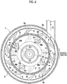
- the dispersion mixing section Y will be further described with reference to Figs. 2 and 5 to 8C .
- the dispersion mixing section Y includes a main body casing 1 including a cylindrical outer peripheral wall portion 4 whose both end opening portions are closed by a front wall portion 2 and a rear wall portion 3, and is configured to include a rotor 5 that is concentrically provided inside the main body casing 1 so as to be driven to rotate, a cylindrical stator 7 that is concentrically disposed inside the main body casing 1 and fixed to the front wall portion 2, a pump drive motor M3 that drives the rotor 5 to rotate, and the like.
- a plurality of rotor blades 6 are provided integrally with the rotor 5 in a state of protruding toward the front side (left side in Fig. 5 ) which is the front wall portion 2 side and being arranged at equal intervals in the circumferential direction.
- the cylindrical stator 7 is provided with a plurality of through-holes 7a and 7b arranged in the circumferential direction, the stator 7 is disposed to be fixed to the front wall portion 2 while being located on the front side of the rotor 5 (left side in Fig. 5 ) and on the radially inner side of the rotor blades 6, and an annular blade chamber 8 in which the rotor blades 6 revolve is formed between the stator 7 and the outer peripheral wall portion 4 of the main body casing 1.
- the feed port 11 through which the preliminary mixture Fp, in which the powder P and the liquid R are premixed by the mixing mechanism 60, is suctioned and introduced to the inside of the main body casing 1 by the rotation of the rotor blades 6 is provided at a position shifted to the outer peripheral side with respect to the center axis (an axial center A3 of the main body casing 1) of the front wall portion 2.
- annular groove 10 is formed on the inner surface of the front wall portion 2 of the main body casing 1, and the feed port 11 is provided in a state of communicating with the annular groove 10.
- a cylindrical discharge portion 12 that discharges the slurry F produced by mixing the powder P and the liquid R is provided at a point in the circumferential direction of the cylindrical outer peripheral wall portion 4 of the main body casing 1 so as to extend in the tangential direction of the outer peripheral wall portion 4 in a state of communicating with the blade chamber 8.
- the slurry F discharged from the discharge portion 12 is supplied to the recirculation mechanism portion 70 through a discharge path 18, and an introduction port 17 that circulates and supplies an undissolved slurry Fr from which bubbles are separated in a cylindrical container 71, which is a separation portion of the recirculation mechanism portion 70, into the main body casing 1 via a circulation path 16 is provided at the center portion (concentric with the axial center A3) of the front wall portion 2 of the main body casing 1.
- a partition plate 15 that partitions the inner peripheral side of the stator 7 into a supply chamber 13 on the front wall portion 2 side and an introduction chamber 14 on the rotor 5 side is provided on the front side of the rotor 5 in a state of rotating integrally with the rotor 5, and scraping blades 9 are provided on the front wall portion 2 side of the partition plate 15.
- a plurality of (in Fig. 7 , four) the scraping blades 9 are concentrically provided at equal intervals in the circumferential direction, and each of the scraping blades 9 is disposed to revolve integrally with the rotor 5 in a state where a tip part 9T enters the annular groove 10.
- the supply chamber 13 and the introduction chamber 14 are configured to communicate with the blade chamber 8 via the plurality of through-holes 7a and 7b of the stator 7, the feed port 11 is configured to communicate with the supply chamber 13, and the introduction port 17 is configured to communicate with the introduction chamber 14.
- the supply chamber 13 and the blade chamber 8 communicate with each other through a plurality of the supply chamber side through-holes 7a arranged at equal intervals in the circumferential direction at a portion of the stator 7 facing the supply chamber 13, and the introduction chamber 14 and the blade chamber 8 communicate with each other through a plurality of the introduction chamber side through-holes 7b arranged at equal intervals in the circumferential direction at a portion of the stator 7 facing the introduction chamber 14.
- the rotor 5 is configured to have a shape in which the front surface swells substantially in the shape of a truncated cone, and is provided with the plurality of rotor blades 6 arranged at equal intervals in a state of protruding forward on the outer peripheral side thereof .
- ten rotor blades 6 are arranged at equal intervals in the circumferential direction.
- the rotor blade 6 is formed to protrude from the outer peripheral side toward the inner peripheral side of the rotor 5 so as to be inclined backward in the rotation direction from the inner peripheral side toward the outer peripheral side, and the inner diameter of the tip parts of the rotor blades 6 is formed to be slightly larger than the outer diameter of the stator 7.
- the rotor 5 is connected to a drive shaft 19 of the pump drive motor M3 that passes through the rear wall portion 3 and is inserted into the main body casing 1, in a state of being concentric with the main body casing 1 in the main body casing 1, and is driven by the pump drive motor M3 to rotate.
- the rotor 5 is configured to generate so-called local boiling (cavitation) on a surface (back surface) 6a which becomes the rear side in the rotation direction of the rotor blade 6 by being driven to rotate in a direction in which the tip part of the rotor blade 6 faces forward when viewed in the axial center direction (viewed in a direction taken along the line VI-VI of Fig. 5 as illustrated in Fig. 6 ).
- the partition plate 15 is configured in a generally funnel shape having an outer diameter slightly smaller than the inner diameter of the stator 7.
- the funnel-shaped partition plate 15 is configured in a shape provided with a funnel-shaped portion 15b which is open at a tubular sliding contact portion 15a with a top protruding in a cylindrical shape at the center thereof, and an annular flat plate portion 15c at the outer peripheral portion of the funnel-shaped portion 15b with both the front surface and the rear surface being in a state perpendicular to the axial center A3 of the main body casing 1.
- the partition plate 15 is attached to attachment portions 5a of the front surface of the rotor 5 via spacing members 20 arranged at a plurality of (in this embodiment, four) points with equal intervals therebetween in the circumferential direction in a posture in which the tubular sliding contact portion 15a of the top faces the front wall portion 2 side of the main body casing 1.
- stirring blades 21 are assembled integrally with the partition plate 15 in a posture facing the rear wall portion 3 side of the main body casing 1, and when the rotor 5 is driven to rotate, the four stirring blades 21 are rotated integrally with the rotor 5.
- the cylindrical introduction port 17 is provided at the center of the front wall portion 2 of the main body casing 1 concentrically with the main body casing 1.
- a throttle portion 14a having a diameter smaller than the inner diameter of the circulation path 16 and smaller than that of the tubular sliding contact portion 15a of the partition plate 15 and thus having a small flow path area is formed.
- the feed port 11 is provided in the front wall portion 2 to be located on the lateral side of the opening portion of the introduction port 17 with respect to the inside of the main body casing 1 in a state in which the opening portion (inlet portion) thereof open to the inside of the main body casing 1 includes a circumferential portion of the annular groove 10 therein. Furthermore, the feed port 11 is provided in the front wall portion 2 of the main body casing 1 in a posture in which the axial center A2 is parallel to the axial center A3 of the main body casing 1 in a plan view (viewed in the up-down direction of Figs.
- the axial center A2 is inclined downward in a direction approaching the axial center A3 of the main body casing 1 as it goes to the front wall portion 2 of the main body casing 1 when viewed in the horizontal direction (viewed in a direction into the paper of Figs. 2 and 5 ) perpendicular to the axial center A3 of the main body casing 1.
- the downward inclination angle of the feed port 11 with respect to the horizontal direction is about 45 degrees as described above.
- the stator 7 is attached to the inner surface (the surface facing the rotor 5) of the front wall portion 2 of the main body casing 1, and is fixed so that the front wall portion 2 of the main body casing 1 and the stator 7 are integrated.
- the plurality of supply chamber side through-holes 7a arranged at the portion facing the supply chamber 13 are formed in a substantially circular shape to be set such that the total flow path area of the plurality of supply chamber side through-holes 7a is smaller than the flow path area of the supply chamber 13.
- the plurality of introduction chamber side through-holes 7b arranged at the portion facing the introduction chamber 14 are formed in a substantially elliptical shape to be set such that the total flow path area of the plurality of introduction chamber side through-holes 7b is smaller than the flow path area of the introduction chamber 14.
- each scraping blade 9 is formed in a rod shape, and a base end part 9B of the rod-shaped scraping blade 9 is fixed to rotate integrally with the rotor 5 in an inclined posture in which the scraping blade 9 is located closer to the front wall portion 2 toward the tip end side of the rod-shaped scraping blade 9 when viewed in the radial direction of the rotor 5 (viewed in a direction into the paper of Fig. 8B ) and is located closer to the radially inner side of the rotor 5 toward the tip end side of the rod-shaped scraping blade 9 when viewed in the axial center direction of the rotor 5 (viewed in a direction into the paper of Fig.
- the scraping blade 9 will be further described with reference to Figs. 6 to 8C .
- the scraping blade 9 is configured in a rod shape provided with the base end part 9B fixed to the partition plate 15, an intermediate portion 9M in a state of being exposed to the supply chamber 13, and the tip part 9T in a state of being fitted in (that is, entering) the annular groove 10 in series in a direction from the base to the tip.
- the base end part 9B of the scraping blade 9 is configured in a substantially rectangular plate shape.
- the intermediate portion 9M of the scraping blade 9 is configured in a substantially triangular prism shape whose transverse sectional shape is generally triangular (in particular, see Fig. 6 ).
- one side surface 9m (hereinafter, sometimes referred to as a radiating surface) facing the forward side in the rotation direction of the rotor 5 among the three side surfaces of the intermediate portion 9M having the triangular prism shape is configured to have a forward downward shape inclined toward the forward side in the rotation direction of the rotor 5 to face the radially outer side (hereinafter, sometimes referred to as diagonally outward) of the rotor 5 in the radial direction (in particular, see Figs. 7 to 8C ).
- the intermediate portion 9M exposed to the supply chamber 13 of the scraping blade 9 is located closer to the radially outer side of the rotor 5 than the tip part 9T fitted into the annular groove 10, and the radiating surface 9m facing the forward side in the rotation direction of the intermediate portion 9M has a forward downward shape inclined toward the forward side in the rotation direction of the rotor 5 and inclined diagonally outward with respect to the radial direction of the rotor 5.
- the preliminary mixture Fp scraped from the annular groove 10 by the tip part 9T of the scraping blade 9 is guided to flow toward the radially outer side of the rotor 5 in the supply chamber 13 by the radiating surface 9m of the intermediate portion 9M of the scraping blade 9.
- the tip part 9T of the scraping blade 9 has a substantially quadrangular prism shape with a substantially rectangular transverse sectional shape, and is configured in an arc shape in a state where an outward side surface 9o facing the radially outer side of the rotor 5 among the four side surfaces when viewed in the axial center direction of the rotor 5 (viewed in the direction into the paper of Fig.
- a scraping surface 9f facing the forward side in the rotation direction of the rotor 5 is configured in a forward downward shape inclined toward the forward side in the rotation direction of the rotor 5 to face the radially outer side (hereinafter, sometimes referred to as diagonally outward) of the rotor 5 in the radial direction.
- the preliminary mixture Fp scraped from the annular groove 10 by the tip part 9T of the scraping blade 9 is directed radially outward of the rotor 5 by the scraping surface 9f of the tip part 9T of the scraping blade 9 and discharged into the supply chamber 13.
- a tip surface 9t of the tip part 9T of the scraping blade 9 is configured to be parallel to the bottom surface of the annular groove 10 in a state where the tip part 9T is fitted in the annular groove 10.
- the four scraping blades 9 configured in the above-described shape are respectively provided with the base end parts 9B fixed to the annular flat plate portion 15c of the partition plate 15 in a form of being arranged in the circumferential direction at intervals of 90 degrees at the central angle in the inclined posture as described above.
- the partition plate 15 provided with the scraping blades 9 is attached to the attachment portions 5a of the front surface of the rotor 5 in a state of being spaced with a gap from the front surface of the rotor 5 by the spacing members 20, and the rotor 5 is disposed in the main body casing 1 in a state where the tubular sliding contact portion 15a of the partition plate 15 is fitted in the introduction port 17 so as to be slidably rotatable.
- the introduction chamber 14 having a tapered shape that decreases in diameter toward the front wall portion 2 side of the main body casing 1 is formed between the swelling front surface of the rotor 5 and the rear surface of the partition plate 15, and the introduction port 17 is configured to communicate with the introduction chamber 14 via the tubular sliding contact portion 15a of the partition plate 15.
- the annular supply chamber 13 communicating with the feed port 11 is formed between the front wall portion 2 of the main body casing 1 and the front surface of the partition plate 15.
- the partition plate 15 rotates integrally with the rotor 5 in a state where the tubular sliding contact portion 15a is in contact with the introduction port 17, and even in the state where the rotor 5 and the partition plate 15 rotate, the state where the introduction port 17 communicates with the introduction chamber 14 via the tubular sliding contact portion 15a of the partition plate 15 is maintained.
- the recirculation mechanism portion (an example of a separation portion) 70 is configured to separate the dissolved liquid in the cylindrical container 71 by specific gravity, and as illustrated in Fig. 2 , is configured to separate, from the slurry F supplied from the discharge portion 12 of the dispersion mixing section Y through the discharge path 18, the undissolved slurry Fr in a state in which the powder P that is not completely dissolved may be contained to be supplied to circulation path 16, and the slurry F in a state in which the powder P is almost completely dissolved to be supplied to the discharge path 22.
- the discharge path 18 and the circulation path 16 are both connected to the lower portion of the cylindrical container 71, and the discharge path 22 is connected to the upper portion of the cylindrical container 71 and the tank 260 which is a supply destination of the slurry F.
- the recirculation mechanism portion 70 is configured such that an introduction pipe to which the discharge path 18 is connected is disposed so as to protrude toward the inside from the bottom surface of the cylindrical container 71, a discharge portion connected to the discharge path 22 is provided in the upper portion of the cylindrical container 71, a circulation portion connected to the circulation path 16 is provided in the lower portion, and a twisted plate that turns the flow of the slurry F discharged from the introduction pipe is disposed at the discharge upper end of the introduction pipe. Accordingly, bubbles of the liquid R can be separated from the slurry F, and the undissolved slurry Fr circulated and supplied to the circulation path 16 can be supplied into the introduction chamber 14 in a state where the bubbles of the liquid R are separated.
- the control unit C controls the overall operation of the slurry production apparatus 200, and controls, for example, the rotating speed of the rotor 5 (the rotor blades 6). Specifically, the control unit C sets the rotating speed of the rotor blades 6 so that the pressure of the outlet region of the supply chamber side through-holes 7a and the introduction chamber side through-holes 7b (throttle through-holes) of the stator 7 becomes equal to or lower than the saturation vapor pressure of the liquid R (3.169 kPa in a case of water at 25°C) over the entire circumference of the outlet region.
- control unit C also controls the dew point temperatures of the powder dry box 230 and the first dry booth 300 and the atmospheric pressures of the powder dry box 230, the first dry booth 300, and the second dry booth 310.
- the powder dry box 230, the first dry booth 300, and the second dry booth 310 are operated to lower the dew point temperatures.
- the cooling device 250 is operated.
- the atmospheric pressure of the powder dry box 230 is set to a positive pressure (a state higher than the outside air pressure by about 5 Pa)
- the atmospheric pressure of the first dry booth 300 is set to a positive pressure (a state higher than the outside air pressure by about 2 to 3 Pa)
- the atmospheric pressure of the second dry booth 310 is set to a negative pressure (a state lower than the outside air pressure by about 2 to 3 Pa).
- the rotor 5 is rotated in a state where suction of the powder P via the powder discharge pipe 45 is stopped by closing the shutter valve 46, and thereafter only the liquid R of the tank 260 is supplied by operating the pump 261 to start the operation of the dispersion mixing section Y.
- the liquid R By supplying the liquid R to the dispersion mixing section Y after rotating the rotor 5, a mechanical seal on the back surface of the rotor 5 is brought into close contact with the rotor 5, and liquid leakage from the back surface of the rotor 5 can be prevented.
- the liquid R is quantitatively supplied to the mixing member 61 of the mixing mechanism 60 continuously in a predetermined amount.
- the shutter valve 46 is opened. Accordingly, the expansion chamber 47 of the powder supply device X is brought into a negative pressure state (about -0.06MPa), and the inside of the introduction portion 41 and the vicinity of the lower opening portion 31b of the hopper 31 are brought into a pressure state between the negative pressure state and the atmospheric pressure state.
- the powder P is supplied from the feeder 220 to the hopper 31 by operating the powder supply device X.
- the powder P stored in the hopper 31 is quantitatively supplied to the mixing member 61 of the mixing mechanism 60 continuously in a predetermined amount via the expansion chamber 47 of the quantitative supply section 40 from the lower opening portion 31b of the hopper 31 by the stirring action of the stirring blade 32A and the negative pressure suction force of the dispersion mixing section Y.
- the quantitative supply section 40 is not used, and a predetermined amount of the powder may be supplied directly from the feeder 220 to the mixing mechanism 60 via the hopper 31.
- the powder is supplied to the mixing mechanism 60 by controlling the supply speed of the feeder 220 so as not to exceed the powder processing capability of the mixing mechanism 60.
- the powder P is supplied from the mixing member 61 of the mixing mechanism 60 to the feed port 11 through the tubular portion 62 of the mixing member 61, and the liquid R is supplied to the feed port 11 through the annular slit 63 in the form of a hollow cylindrical vortex without a break, the powder P and the liquid R are premixed by the feed port 11, and the preliminary mixture Fp is introduced into the annular groove 10.
- the powder discharge port 221 and the shutter valve 46 are closed to stop the suction of the powder P via the powder discharge pipe 45 such that the supply of the powder to the dispersion mixing section Y from the powder supply device X is stopped.
- the preliminary mixture Fp that flows through the feed port 11 and is introduced into the annular groove 10 is scraped by the tip parts 9T of the scraping blades 9 revolving while being fitted in the annular groove 10, and the scraped preliminary mixture Fp schematically flows in the supply chamber 13 in the rotation direction of the rotor 5 along the front surface of the funnel-shaped portion 15b and the front surface of the annular flat plate portion 15c in the partition plate 15, further flows into the blade chamber 8 through the supply chamber side through-holes 7a of the stator 7, flows in the blade chamber 8 in the rotation direction of the rotor 5, and is discharged from the discharge portion 12.
- the preliminary mixture Fp introduced into the annular groove 10 undergoes a shearing action when scraped by the tip parts 9T of the scraping blades 9.
- a shearing action acts between the outward side surface 9o of the tip part 9T of the scraping blade 9 and the inward inner surface of the annular groove 10 on the inner side, and between the inward side surface 9i of the tip part 9T of the scraping blade 9 and the outward inner surface of the annular groove 10 on the inner side.
- a shearing action also acts when the preliminary mixture Fp passes through the supply chamber side through-holes 7a of the stator 7.
- the shearing force can be applied to the preliminary mixture Fp in the supply chamber 13
- the preliminary mixture Fp to be scraped out is mixed by receiving the shearing action from the scraping blades 9 and the supply chamber side through-holes 7a. Accordingly, the dispersion of the powder P with the liquid R is performed more favorably. Therefore, such a preliminary mixture Fp can be supplied, and good dispersion of the powder P with the liquid R in the blade chamber 8 can be expected.
- the slurry F discharged from the discharge portion 12 is supplied to the recirculation mechanism portion 70 through the discharge path 18, and in the recirculation mechanism portion 70, the undissolved slurry Fr in a state of containing the powder P that is not completely dissolved and the slurry F in a state where the powder P is almost completely dissolved are separated from each other, and the bubbles of the liquid R are separated.
- the undissolved slurry Fr is supplied again to the introduction port 17 of the dispersion mixing section Y through the circulation path 16, and the slurry F is supplied to the tank 260 through the discharge path 22.
- the undissolved slurry Fr is introduced into the introduction chamber 14 via the throttle portion 14a of the introduction port 17 in a state where the flow rate is limited.
- the undissolved slurry Fr receives a shearing action by the plurality of rotating stirring blades 21, are further finely crushed, and are also further crushed by receiving a shearing action when passing through the introduction chamber side through-holes 7b.
- the undissolved slurry Fr is introduced into the blade chamber 8 in a state where the flow rate is limited via the introduction chamber side through-holes 7b.
- the slurry F that is crushed by receiving the shearing action by the rotor blades 6 rotating at a high speed and the generation of local boiling (cavitation) at the surface (back surface) 6a which becomes the rear side in the rotation direction of the rotor blade 6 and is thus further reduced in the amount of aggregates (mass) of the powder P is mixed with the slurry F from the supply chamber 13 and is discharged from the discharge portion 12.
- the rotating speed of the rotor blades 6 is set by the control unit so that the pressure in the blade chamber 8 which is the outlet region of the supply chamber side through-holes 7a and the introduction chamber side through-holes 7b of the stator 7 becomes equal to or lower than the saturation vapor pressure of the liquid R over the entire circumference, and the rotor blades 6 are rotated at the set rotating speed.
- the pressure in the blade chamber 8 which is the outlet region becomes equal to or lower than the saturation vapor pressure of the liquid R (3.169 kPa in the case of water at 25°C) over the entire circumference. Therefore, at least in the region in the blade chamber 8 immediately after passing through the supply chamber side through-holes 7a and the introduction chamber side through-holes 7b of the stator 7, the generation of fine bubbles (microbubbles) is promoted by vaporization of the liquid R, so that the region enters a state of being formed as a fine bubble region in which a large number of fine bubbles generated continuously over the entire circumference in the blade chamber 8.
Landscapes
- Chemical & Material Sciences (AREA)
- Chemical Kinetics & Catalysis (AREA)
- Dispersion Chemistry (AREA)
- Engineering & Computer Science (AREA)
- General Chemical & Material Sciences (AREA)
- Electrochemistry (AREA)
- Materials Engineering (AREA)
- Health & Medical Sciences (AREA)
- General Health & Medical Sciences (AREA)
- Toxicology (AREA)
- Manufacturing & Machinery (AREA)
- Drying Of Solid Materials (AREA)
- Secondary Cells (AREA)
- Battery Electrode And Active Subsutance (AREA)
- Drying Of Gases (AREA)
Abstract
Description
- Certain embodiments of the present invention relate to a slurry production apparatus.
- Hitherto, a slurry production apparatus for producing a slurry by mixing a powder and a liquid has been used. Japanese Patent No.
5625216 - Among powders used as materials for a slurry, there are some powders that absorb moisture in the air and deteriorate or solidify. In a case of producing a slurry with an apparatus of Japanese Patent No.
5625216 5625216 - Therefore, it is considered that in order to prevent the powder from absorbing moisture, a device for each portion such as a device for a portion in which the powder is fed into the hopper and a device for a portion in which the powder is stirred is installed in a sealed container such as a glove box which is dehumidified and reduced in dew point temperature. The glove box is a box whose inside is blocked from the outside air, and a hand can be inserted into the inside via a sealed glove from the outside of the glove box.
- However, the space in the glove box is a limited space that allows a worker to work via the glove. Furthermore, the work range is narrow due to work via the glove, and the carry-in and discharge of articles into the glove box are limited by the size of a pass box (opening portion provided in the glove box). For this reason, it is difficult to dispose the entire dispersion apparatus including the device for each portion such as the device for the portion in which the powder is fed into the hopper, the device for the portion in which the powder is stirred, and the like in the glove box without deteriorating the dew point temperature. In addition, even in a case where the device for each portion is disposed in the glove box, size restrictions are imposed on the device for each portion and work is restricted. Furthermore, when the devices for the respective portions are disposed in the glove box, it is difficult to connect the devices for the portions to form the dispersion apparatus.
- Embodiments of the present invention have been made in view of the above-described problems, and it is desirable to provide a slurry production apparatus capable of suppressing a reduction in slurry quality.
- A characteristic configuration of a slurry production apparatus for achieving the above obj ect includes : a mixing device that mixes a liquid and a powder to produce a slurry; a powder supply device that supplies the powder to the mixing device; a powder dry box that accommodates at least an opening portion of the powder supply device; and a first dry booth that accommodates the mixing device and the powder dry box.
- According to the above characteristic configuration, since the opening portion of the powder supply device is accommodated in the powder dry box, a situation where the powder comes into contact with moist air can be avoided, and deterioration of the quality of the slurry can be suppressed.
- Further, the mixing device and the powder dry box are accommodated in the first dry booth. Therefore, the opening portion of the powder supply device is accommodated in the powder dry box and further accommodated in the first dry booth, so that contact between the powder and moist air can be further suppressed. In addition to the opening portion of the powder supply device, the mixing device is also accommodated in the first dry booth. Therefore, even in a case where the powder is supplied from the powder supply device to the mixing device, contact between the powder and moist air can be suppressed. Therefore, introduction of the powder that absorbs moisture and deteriorates in quality into the mixing device can be suppressed, and as a result, deterioration of the quality of the slurry produced by the mixing device can be suppressed.
- A further characteristic configuration of the slurry production apparatus for achieving the above object further includes: a second dry booth that accommodates the first dry booth.
- According to the above characteristic configuration, since the first dry booth is accommodated in the second dry booth, the inside of the first dry booth can be further isolated from outside air. Accordingly, contact of the powder with moist air in the opening portion of the powder supply device accommodated in the first dry booth and the powder dry box can be further suppressed. Furthermore, even when the powder is supplied from the powder supply device to the mixing device, contact of the powder with moist air can be further suppressed. Therefore, deterioration of the quality of the slurry can be further suppressed.
- A further characteristic configuration of the slurry production apparatus for achieving the above object is that a first set dew point temperature of the first dry booth is higher than a second set dew point temperature of the powder dry box.
- In the powder dry box, there is a possibility that the powder may come into contact with the air when the powder is fed into the powder supply device or when the powder is stirred. On the other hand, since the mixing device that mixes the liquid and the powder is in a closed space, the possibility that the powder may be directly exposed to the air is small in the first dry booth that accommodates the mixing device. Therefore, the dryness required for the first dry booth is lower than that of the powder dry box. As in the above characteristic configuration, since the first set dew point temperature of the first dry booth can be set to higher than the second set dew point temperature of the powder dry box, an increase in running cost can be suppressed.
- Furthermore, the dew point temperature can be lowered stepwise from the outside toward the first dry booth and the powder dry box. Therefore, it is easy to adjust the dew point temperature inside the powder dry box to be low, and the running cost can be reduced.
- A further characteristic configuration of the slurry production apparatus for achieving the above object is that an atmospheric pressure of the powder dry box is higher than an atmospheric pressure of the first dry booth.
- According to the above characteristic configuration, since the atmospheric pressure of the powder dry box is higher than the atmospheric pressure of the first dry booth, the flow of the air of the first dry booth into the powder dry box can be suppressed. Accordingly, contact of the powder with the moist air in the opening portion of the powder supply device in the powder dry box can be further suppressed.
- A further characteristic configuration of the slurry production apparatus for achieving the above object is that the slurry is a positive electrode active material slurry, a negative electrode active material slurry, or a solid electrolyte slurry used for manufacturing an all-solid-state battery.
- As described above, in the above slurry production apparatus, deterioration of quality due to contact of the powder used for producing the slurry with moist air can be suppressed. Therefore, by using the slurry production apparatus for producing a positive electrode active material slurry, a negative electrode active material slurry, or a solid electrolyte slurry as in the above characteristic configuration, deterioration of the quality of the slurry can be suppressed. Accordingly, deterioration of the quality of an all-solid-state battery can be suppressed.
- A further characteristic configuration of the slurry production apparatus for achieving the above object is that the powder contains a sulfide solid electrolyte.
- As described above, in the above slurry production apparatus, in a case where a slurry is produced using a sulfide solid electrolyte that is a powder, contact of the powder with moist air can be suppressed. Therefore, in a case of using the sulfide solid electrolyte as the powder as in the above characteristic configuration, the generation of toxic hydrogen sulfide due to the contact of the sulfide solid electrolyte with moist air can be suppressed. Therefore, by producing a slurry in a state where the contact between the sulfide solid electrolyte and moist air is suppressed and manufacturing a battery, a decrease in battery performance such as a decrease in output characteristics and a reduction in service life can be suppressed.
- Furthermore, since generation of hydrogen sulfide can be suppressed, it is not necessary to provide a separate device such as a filter device for removing hydrogen sulfide, or the running cost can be reduced by reducing driving of the device.
- A further characteristic configuration of the slurry production apparatus for achieving the above object is that a filter is provided in an exhaust portion of the first dry booth.
- According to the above characteristic configuration, discharge of odors, harmful gases, and the like to the outside of the first dry booth is suppressed by filtering the odors, harmful gases, and the like using the filter.
- A further characteristic configuration of the slurry production apparatus for achieving the above object further includes: a dehumidifying unit that sends air at a third dew point temperature into the powder dry box; and a control unit that adjusts a first flow rate of the air at the third dew point temperature sent from the dehumidifying unit into the powder dry box so as to adjust a dew point temperature of the powder dry box to a second set dew point temperature, in which, when the dew point temperature of the powder dry box reaches the second set dew point temperature or lower, the control unit performs at least one of an adjustment of a second flow rate of the air at the third dew point temperature sent from the dehumidifying unit into the first dry booth, and an adjustment of a third flow rate of air sent from the powder dry box into the first dry booth.
- According to the above characteristic configuration, the control unit adjusts the first flow rate of the air at the third dew point temperature sent from the dehumidifying unit into the powder dry box so as to adjust the powder dry box to the second set dew point temperature. Furthermore, when the dew point temperature of the powder dry box reaches the desired second set dew point temperature or lower, the control unit adjusts the second flow rate of the air at the third dew point temperature sent from the dehumidifying unit into the first dry booth. Accordingly, a portion of the air at the third dew point temperature that has been sent from the dehumidifying unit into the powder dry box is used for adjusting the dew point temperature of the first dry booth. Accordingly, the air at the third dew point temperature from the dehumidifying unit can be effectively utilized to cause the first dry booth to reach the first set dew point temperature.
- In addition, when the dew point temperature of the powder dry box reaches the desired second set dew point temperature or lower, the control unit adjusts the third flow rate of the air sent from the powder dry box into the first dry booth. Accordingly, while maintaining the inside of the powder dry box at the desired second set dew point temperature, the air in the powder dry box can be effectively utilized to cause the first dry booth to reach the desired first set dew point temperature.
-
-
Fig. 1 is a view showing an outline of a slurry production apparatus. -
Fig. 2 is a schematic configuration view of a dispersion system including a centrifugal dispersion mixing section. -
Fig. 3 is a longitudinal sectional view illustrating a main part of a powder supply device. -
Fig. 4 is a cross-sectional view in a direction taken along the line IV-IV ofFig. 3 . -
Fig. 5 is a longitudinal side view of the centrifugal dispersion mixing section. -
Fig. 6 is a cross-sectional view in a direction taken along the line VI-VI ofFig. 5 . -
Fig. 7 is an exploded perspective view illustrating an assembly configuration of a front wall portion of a main body casing, a stator, a partition plate, and a rotor. -
Figs. 8A to 8C are schematic configuration views of the partition plate. - As illustrated in
Fig. 1 , aslurry production apparatus 200 according to the present embodiment is configured to include adispersion system 100, adehumidifying unit 233, a powderdry box 230, a firstdry booth 300, and a seconddry booth 310, and a control unit C. - The configuration of each part of the
dispersion system 100 will be briefly described below, and the detailed configuration will be described in detail later. - The
dispersion system 100 is configured to include a powder supply device X, a dispersion mixing section Y, amixing mechanism 60, arecirculation mechanism portion 70, acooling device 250, atank 260, and apressure vent portion 270. - The powder supply device X is configured to include a
feeder hopper 210, afeeder 220, ahopper 31, and a quantitative supply section 40 (Fig. 2 and the like). - The
feeder hopper 210 is a hopper that temporarily stores a powder P dry-transported from upstream. Thefeeder hopper 210 has anair vent 211 connected to the powderdry box 230. Theair vent 211 discharges the dry air inside thefeeder hopper 210 into the firstdry booth 300 when the internal pressure of thefeeder hopper 210 increases with the feeding of the powder P from the upstream. Theair vent 211 is provided with a check valve, and when thefeeder hopper 210 is not under pressure, thefeeder hopper 210 is preferably closed so that the powder P is not affected by moisture. - A filter may be provided at the discharge port of the
air vent 211, and the dry air inside thefeeder hopper 210 may be discharged from theair vent 211 into the firstdry booth 300 via the filter. Alternatively, a filter may be provided at the discharge port of theair vent 211 so that the dry air inside thefeeder hopper 210 is not discharged into the firstdry booth 300 but may be opened to the atmosphere. - The
feeder 220 discharges the powder P stored in thefeeder hopper 210 from a powder discharge port 221 (an example of an opening portion) while measuring the powder P. Thefeeder 220 is, for example, a screw type feeder. Thepowder discharge port 221 is disposed inside the powderdry box 230. The powder P discharged from thepowder discharge port 221 is fed into thehopper 31 from anupper opening portion 31a of thehopper 31. - The
hopper 31 is a member having an inverted conical shape which is decreased in diameter from the upper portion toward the lower portion, and causes the powder P received from theupper opening portion 31a to be discharged from alower opening portion 31b and supplied to themixing mechanism 60 via the quantitative supply section 40 (Fig. 2 and the like). - The
mixing mechanism 60 mixes a liquid R (or slurry F) supplied from thetank 260 with the powder P. - The dispersion mixing section Y disperses and mixes the powder P and the liquid R mixed by the
mixing mechanism 60. - The
recirculation mechanism portion 70 circulates and supplies the liquid R containing the powder P that has not been completely dissolved (hereinafter, undissolved slurry Fr), to the dispersion mixing section Y. - The
cooling device 250 is a device that cools the dispersion mixing section Y in order to suppress alteration of the slurry F due to a temperature rise. Specifically, thecooling device 250 is a cold water jacket through which supplied cold water flows, and is provided so as to cover a main body casing 1 of the dispersion mixing section Y and therecirculation mechanism portion 70. - The dew point temperature in the first
dry booth 300 is set to -40°C (first set dew point temperature), and thecooling device 250 is accommodated in the firstdry booth 300. Accordingly, the occurrence of condensation on the surface of thecooling device 250 can be suppressed, which is desirable. - The
tank 260 is configured to continuously supply the liquid R in thetank 260 to the dispersion mixing section Y at a set flow rate. Therefore, thetank 260 functions as a solvent supply source that supplies the liquid R to the dispersion mixing section Y. Furthermore, the slurry F is supplied to thetank 260 from therecirculation mechanism portion 70. Therefore, thetank 260 functions as a slurry recovery source for recovering the slurry F. - The
pressure vent portion 270 reduces the pressure in thetank 260 by exhausting gas from thetank 260. Specifically, thepressure vent portion 270 is a gas flow path, and connects the inside of thetank 260 to the powderdry box 230 via a valve. A gas flow path branched from the valve to exhaust the gas from thetank 260 to the outside is provided, and a filter 271 is disposed in the gas flow path. When the gas is exhausted from thetank 260 to the outside, the gas in thetank 260 is exhausted through the filter 271. Accordingly, malodor and scattering of substances are suppressed. - In the
dispersion system 100 of theslurry production apparatus 200, the slurry F is generally produced as follows. The powder P supplied from the powder supply device X and the liquid R (or slurry F) supplied from thetank 260 by apump 261 are mixed by themixing mechanism 60 and supplied to the dispersion mixing section Y. In the dispersion mixing section Y, the powder P and the liquid R are dispersed and mixed and sent to therecirculation mechanism portion 70. Therecirculation mechanism portion 70 circulates and supplies the liquid R containing the powder P that has not been completely dissolved (hereinafter, undissolved slurry Fr) to the dispersion mixing section Y, and sends the slurry F to thetank 260. The slurry F inside thetank 260 is stirred by a tank stirring motor M4. - The
dehumidifying unit 233 has adehumidifying portion 233a and a flowrate adjusting portion 233b, and dehumidifies the air in the powderdry box 230 and the firstdry booth 300. The air inside the powderdry box 230 is adjusted to a dew point temperature of, for example, -80°C, and the air inside the firstdry booth 300 is adjusted to a dew point temperature of, for example, -40°C. Therefore, thedehumidifying portion 233a is configured to be able to supply air having a dew point temperature of -80°C or lower, for example, a dew point temperature of -80°C. Hereinafter, such a dew point temperature relationship will be described as an example. - For example, the
dehumidifying portion 233a sends air having a dew point temperature of -80°C (third dew point temperature) into the powderdry box 230, which will be described later, via the flowrate adjusting portion 233b at a first flow rate Q1. The flowrate adjusting portion 233b controls the first flow rate Q1 according to the control of the control unit C, and adjusts the dew point temperature in the powderdry box 230 to -80°C (second set dew point temperature). - For example, the
dehumidifying portion 233a sends air having a dew point temperature of -80°C (third dew point temperature) into the firstdry booth 300, which will be described later, via the flowrate adjusting portion 233b at a second flow rate Q2. The flowrate adjusting portion 233b controls the second flow rate Q2 according to the control of the control unit C. - The flow
rate adjusting portion 233b is a damper whose opening degree can be adjusted according to the control of the control unit C. By adjusting the opening degree of the flowrate adjusting portion 233b, the first flow rate Q1 of air sent from thedehumidifying portion 233a into the powderdry box 230 and the second flow rate Q2 of air sent from thedehumidifying portion 233a into the firstdry booth 300 are adjusted. - In the present embodiment, it is assumed that the flow rate of the air having a dew point temperature of -80°C (third dew point temperature) sent out by the
dehumidifying portion 233a is constant. Therefore, the sum of the first flow rate Q1 from thedehumidifying portion 233a to the powderdry box 230 and the second flow rate Q2 from thedehumidifying portion 233a to the firstdry booth 300 is constant. However, the flow rate of the air having a dew point temperature of -80°C (third dew point temperature) sent out by thedehumidifying portion 233a may not be constant. - The air sent from the
dehumidifying portion 233a into the powderdry box 230 returns to thedehumidifying portion 233a via adamper 234, which will be described later. In addition, the air that has passed through the firstdry booth 300 from thedehumidifying portion 233a returns to thedehumidifying portion 233a via afilter 301, which will be described later. In addition, the air that has passed through the powderdry box 230, adamper 237, which will be described later, and the firstdry booth 300dehumidifying portion 233a returns to thedehumidifying portion 233a via thefilter 301, which will be described later. - In the above description, the dew point temperature of the air sent out by the
dehumidifying portion 233a is -80°C. However, the dew point temperature is not particularly limited as long as the powder treated by theslurry production apparatus 200 can be prevented from coming into contact with moist air. For example, the dew point temperature of the air sent out by thedehumidifying portion 233a may be -40°C to -90°C. - Similarly, in the above description, the dew point temperature in the powder
dry box 230 is set to -80°C and the dew point temperature in the firstdry booth 300 is set to -40°C. However, the dew point temperatures are not particularly limited as long as the powder treated by theslurry production apparatus 200 can be prevented from coming into contact with moist air. For example, the dew point temperature in the powderdry box 230 may be -40°C to -90°C. The dew point temperature in the firstdry booth 300 may be -30°C or lower. The dew point temperature in the firstdry booth 300 may be any dew point temperature that does not cause condensation in thecooling device 250 installed in the firstdry booth 300, and for example, may be -20°C to -30°C. - In the above description, the
dehumidifying unit 233 dehumidifies the air in the powderdry box 230 and the firstdry booth 300 but may also dehumidify the air in the seconddry booth 310. - The powder
dry box 230, the firstdry booth 300, and the seconddry booth 310 are partitions separated from the external space in order to maintain the atmosphere of the internal space in a predetermined state. In particular, the powderdry box 230 is a partition for maintaining only the atmosphere of a limited necessary portion in theslurry production apparatus 200 in a predetermined state. For example, these partitions are synthetic resin panels. However, the powderdry box 230, the firstdry booth 300, and the seconddry booth 310 may be used to block the powder P in the internal spaces from moisture and maybe made of various materials such as a vinyl curtain, materials having heat insulation, or metal. - Regarding the relationship between the powder
dry box 230, the firstdry booth 300, and the seconddry booth 310 described above, the powderdry box 230 is accommodated in the firstdry booth 300, and the firstdry booth 300 is accommodated in the seconddry booth 310. - Hereinafter, each of the powder
dry box 230, the firstdry booth 300, and the seconddry booth 310 will be described. - The powder
dry box 230 accommodates the powder discharge port 221 (the example of the opening portion) of thefeeder 220 which is an opening portion of the powder supply device X, and theupper opening portion 31a (an example of the opening portion) of thehopper 31. - As described above, the air having a dew point temperature of -80°C (third dew point temperature) is sent into the powder
dry box 230 from thedehumidifying portion 233a such that the air in the space is adjusted to -80°C (second set dew point temperature) . Therefore, since the opening portions such as thepowder discharge port 221, theupper opening portion 31a, and the like of the powder supply device X are accommodated in the powderdry box 230 with the dew point temperature adjusted as described above, a situation where the powder comes into contact with the moist air can be avoided, and the deterioration of the quality of the slurry can be suppressed. - In particular, the powder P discharged from the
powder discharge port 221 of the powder supply device X falls inside the powderdry box 230 and is fed into thehopper 31 from theupper opening portion 31a of thehopper 31. In addition, since theupper opening portion 31a is also accommodated in the powderdry box 230, contact of the powder with moist air is suppressed. - The powder
dry box 230 is provided with thedamper 234 that causes the powderdry box 230 to communicate with thedehumidifying portion 233a of thedehumidifying unit 233, and thedamper 237 that opens and closes communication between the powderdry box 230 and the firstdry booth 300. The degree of opening and closing of thedamper 234 and thedamper 237 can be adjusted. Thedamper 237 adjusts the degree of opening and closing according to the control of the control unit C, and allows the air at -80°C (second set dew point temperature) in the powderdry box 230 to be sent to the firstdry booth 300 at a third flow rate Q3. Thedamper 234 adjusts the degree of opening and closing according to the control of the control unit C, and allows the air in the powderdry box 230 to be returned to thedehumidifying portion 233a of thedehumidifying unit 233 at a fourth flow rate Q4. - In the present embodiment, the dew point temperatures of the powder
dry box 230 and the firstdry booth 300 are adjusted according to the control of the control unit C, for example, as follows. - First, by adjusting the opening degree of the flow
rate adjusting portion 233b, the air having a dew point temperature of -80°C (third dew point temperature) is sent from thedehumidifying portion 233a into the powderdry box 230 at the first flow rate Q1. Then, the air sent into the powderdry box 230 returns to thedehumidifying portion 233a via thedamper 234 at the fourth flow rate Q4. In the present embodiment, the fourth flow rate Q4 is substantially the same as the first flow rate Q1, and the air is circulated between the dehumidifyingportion 233a and the powderdry box 230 until the dew point temperature in the powderdry box 230 reaches -80°C (second set dew point temperature). That is, the air having a dew point temperature of -80°C (second set dew point temperature) is continuously sent from thedehumidifying portion 233a into the powderdry box 230 until the dew point temperature in the powderdry box 230 reaches -80°C (second set dew point temperature). - Next, when the dew point temperature in the powder
dry box 230 reaches -80°C (second set dew point temperature), thedamper 234 is closed. Then, by adjusting the opening degree of the flowrate adjusting portion 233b, the air having a dew point temperature of -80°C (third dew point temperature) is sent from thedehumidifying portion 233a into the firstdry booth 300 at the second flow rate Q2. Furthermore, by adjusting the opening degree of thedamper 237 according to the control of the control unit C, the air at -80°C (second set dew point temperature) in the powderdry box 230 is sent into the firstdry booth 300 at the third flow rate Q3. - By such control, the inside of the powder
dry box 230 can be adjusted to -80°C (second set dew point temperature), and the inside of the firstdry booth 300 can be adjusted to -40°C (first set dew point temperature). - Here, in the present embodiment, as illustrated in
Fig. 1 , thefeeder hopper 210 andfeeder 220 of the powder supply device X and the powderdry box 230 are placed on astand 280 and disposed above the dispersion mixing section Y (mixing device) . Theupper opening portion 31a of thehopper 31 is disposed above thestand 280. The lower opening portion (31b) of thehopper 31 is disposed below thestand 280. - In such an arrangement, the
damper 237 is provided in a lower portion of the powderdry box 230 so as to open downward. Accordingly, when thedamper 237 is opened, the air having a dew point temperature of -80°C in the powderdry box 230 is sent from the powderdry box 230 so as to advance downward in the firstdry booth 300. - In addition, the first
dry booth 300 accommodates the powderdry box 230 and the mixing device. For example, the mixing device includes the dispersion mixing section Y, themixing mechanism 60, therecirculation mechanism portion 70, thecooling device 250, thetank 260, and thepressure vent portion 270. - In the present embodiment, as illustrated in
Fig. 1 , thefeeder hopper 210, thefeeder 220, theair vent 211, and the like are not accommodated in the firstdry booth 300, but may also be accommodated in the first dry booth. - As described above, the air having a dew point temperature of -80°C (third dew point temperature) is sent from the
dehumidifying portion 233a into the firstdry booth 300 such that the air in the space is adjusted to -40°C (first set dew point temperature). The opening portions such as thepowder discharge port 221 and theupper opening portion 31a of the powder supply device X are accommodated in the powderdry box 230 and the firstdry booth 300 with adjusted dew point temperatures, so that contact of the powder with moist air can be further suppressed. - In addition to the opening portion of the powder supply device X, the mixing device is also accommodated in the first
dry booth 300. Therefore, even in a case where the powder is supplied from the powder supply device X to the mixing device, contact of the powder with moist air can be suppressed. Therefore, introduction of the powder that absorbs moisture and deteriorates in quality into the mixing device can be suppressed, and as a result, deterioration of the quality of the slurry produced by the mixing device can be suppressed. - Furthermore, as described above, the set dew point temperature of the air in the first
dry booth 300 is -40°C (first set dew point temperature), and the set dew point temperature of the air in the powderdry box 230 is higher than -80°C (second set dew point temperature). In this case, the dew point temperature can be managed more precisely by providing a plurality of dehumidifying units. The plurality of dehumidifying units include a dehumidifying unit for adjusting the dew point temperature of the firstdry booth 300 and a dehumidifying unit for adjusting the dew point temperature of the powderdry box 230. - In the powder
dry box 230, there is a possibility that the powder may come into contact with the air when the powder is fed into the powder supply device X or when the powder is stirred. On the other hand, since the mixing device that mixes the liquid and the powder is in a closed space, the possibility that the powder may be directly exposed to the air is small in the firstdry booth 300 that accommodates the mixing device. Therefore, the dryness required for the firstdry booth 300 is lower than that of the powderdry box 230. As described above, since the set dew point temperature (-40°C: first set dew point temperature) of the firstdry booth 300 can be set to higher than the set dew point temperature (-80°C: second set dew point temperature) of the powder dry box, an increase in running cost can be suppressed. - Furthermore, the dew point temperature can be lowered stepwise from the outside toward the first
dry booth 300 and the powderdry box 230. Therefore, it is easy to adjust the dew point temperature inside the powderdry box 230 to be low, and the running cost can be reduced. - Although the air exhausted from the first
dry booth 300 returns to thedehumidifying unit 233, it is preferable that thefilter 301 is provided in an exhaust portion of the firstdry booth 300. Thefilter 301 is preferably formed of a material capable of filtering odors, harmful gases, and the like. Accordingly, introduction of odors, harmful gases, and the like into thedehumidifying unit 233 and further into the powderdry box 230 and the firstdry booth 300 is suppressed, and contamination of the air therein can be suppressed. - The second
dry booth 310 accommodates the firstdry booth 300. - Since the first
dry booth 300 is accommodated in the seconddry booth 310, the inside of the firstdry booth 300 can be further isolated from outside air. Accordingly, contact of the powder with moist air in the opening portions of the powder supply device X accommodated in the firstdry booth 300 and the powderdry box 230 can be further suppressed. Furthermore, even when the powder is supplied from the powder supply device X to the mixing device, contact of the powder with moist air can be further suppressed. Therefore, deterioration of the quality of the slurry can be further suppressed. - In the present embodiment, as illustrated in
Fig. 1 , thefeeder hopper 210, thefeeder 220, theair vent 211, and the like are not accommodated in the seconddry booth 310, but may also be accommodated in the second dry booth. - By the control of the control unit C, the atmospheric pressure in the powder
dry box 230 is adjusted to a positive pressure higher than the atmospheric pressure outside the second dry booth 310 (hereinafter referred to as "outside air pressure") . The atmospheric pressure of the powderdry box 230 is, for example, higher than the outside air pressure by about 5 Pa. Accordingly, the flow of outside air into the powderdry box 230 can be suppressed. Therefore, the dew point temperature in the powderdry box 230 can be kept low, and contact of the powder with the moist air in the opening portions of the powder supply device X can be further suppressed. - In addition, by the control of the control unit C, the atmospheric pressure of the first
dry booth 300 is adjusted to a positive pressure higher than the outside air pressure. The atmospheric pressure of the firstdry booth 300 is higher than the outside air pressure, for example, by about 2 to 3 Pa. Accordingly, the flow of outside air into the firstdry booth 300 can be suppressed. Therefore, contact of the powder with the moist air in the opening portions of the powder supply device X in the powderdry box 230 accommodated in the firstdry booth 300 can be further suppressed. Furthermore, even when the powder is supplied from the powder supply device X to the mixing device, contact of the powder with moist air can be further suppressed. - Although described above, the
dehumidifying unit 233 may dehumidify the air in the seconddry booth 310 as indicated by a two-dot chain line inFig. 1 in addition to the air in the powderdry box 230 and the firstdry booth 300. In addition, even in a case where the atmospheric pressure of the seconddry booth 310 is set to be higher than the atmospheric pressure of the firstdry booth 300, it is possible to prevent the outside air from flowing into the firstdry booth 300. - As described above, the atmospheric pressure of the powder dry box 230 (higher than the outside air pressure by about 5 Pa) is higher than the atmospheric pressure of the first dry booth 300 (higher than the outside air pressure by about 2 to 3 Pa). Therefore, the flow of the air of the first
dry booth 300 into the powderdry box 230 can be suppressed. Accordingly, contact of the powder with the moist air in the opening portions of the powder supply device X in the powderdry box 230 can be further suppressed. - Moreover, by the control of the control unit C, the atmospheric pressure of the second
dry booth 310 is adjusted to a negative pressure lower than the outside air pressure (lower than the outside air pressure by about 2 to 3 Pa). Therefore, the outflow of the air in the seconddry booth 310 can be suppressed. Accordingly, the outflow of the air in the space of any of the powderdry box 230, the firstdry booth 300, and the seconddry booth 310 is suppressed, and the outflow of, for example, odors and harmful gases in these spaces can be suppressed. - Since the atmospheric pressures in the powder
dry box 230 and the firstdry booth 300 are more positive than the outside air pressure, there are cases where the air in the powderdry box 230 and the firstdry booth 300 flows to the seconddry booth 310. By causing the atmospheric pressure in the seconddry booth 310 to be a negative pressure lower than the outside air pressure, while suppressing the flow of the air from the outside into the powderdry box 230 and the firstdry booth 300, and the outflow of odors, harmful gases, and the like in the powderdry box 230, the firstdry booth 300, and the seconddry booth 310 can be suppressed. - Here, in a case where the dew point temperature of the powder
dry box 230 is maintained at -80°C or lower and the dew point temperature of the firstdry booth 300 is maintained at -40°C or lower, the air flow is as follows, for example. First, air flows in a circulation of a flow from thedehumidifying unit 233 through the powderdry box 230 and the firstdry booth 300 to thedehumidifying unit 233. Second, air flows in a circulation of a flow from thedehumidifying unit 233 through the firstdry booth 300 to thedehumidifying unit 233. - By configuring the air flow in this way, the
dehumidifying unit 233 can be shared by the powderdry box 230 and the firstdry booth 300, and there is no need to separately provide the dehumidifying unit for the firstdry booth 300 and thedehumidifying unit 233, thereby suppressing an increase in cost. - The control unit C is a calculation processing device including a CPU, a storage unit, and the like, and controls the overall operation of the
slurry production apparatus 200. In particular, the control unit C adjusts the flow rate of the air from thedehumidifying unit 233 to the powderdry box 230 and the firstdry booth 300, and adjusts the flow rate of the air from the powderdry box 230 to the firstdry booth 300. - First, the control unit C adjusts the first flow rate Q1 of the air at -80°C (third dew point temperature) sent from the
dehumidifying portion 233a into the powderdry box 230 so as to adjust the dew point temperature of the powderdry box 230 to -80°C (second set dew point temperature) . In this case, the control unit C adjusts the first flow rate Q1 by adjusting the opening degree of the flowrate adjusting portion 233b. However, in this case, since the dew point temperature of the powderdry box 230 does not reach -80°C or lower, the control unit C adjusts the opening degree of the flowrate adjusting portion 233b so as to cause the air at -80°C (third dew point temperature) from thedehumidifying portion 233a to be sent only into the powderdry box 230 and not sent into the firstdry booth 300. Therefore, the first flow rate Q1 in this case may be, for example, the maximum exhaust amount of thedehumidifying portion 233a. - In addition, the control unit C opens the
damper 234 of the powderdry box 230 so as to cause the air sent into the powderdry box 230 to return to thedehumidifying portion 233a via thedamper 234 at the fourth flow rate Q4. For example, the control unit C adjusts the fourth flow rate Q4 and the first flow rate Q1 to approximately the same level, and circulates the air between the dehumidifyingportion 233a and the powderdry box 230. Accordingly, the dew point temperature of the powderdry box 230 is stabilized at -80°C (second set dew point temperature). - Next, when the dew point temperature of the powder
dry box 230 reaches -80°C (second set dew point temperature) or lower, the control unit C closes thedamper 234 and performs the following adjustment. - The control unit C controls the flow
rate adjusting portion 233b to perform a first adjustment of the second flow rate Q2 of the air at -80°C (third dew point temperature) sent from thedehumidifying portion 233a into the firstdry booth 300. In the present embodiment, the flow rate of the air at -80°C (third dew point temperature) sent from thedehumidifying portion 233a is the sum of the first flow rate Q1 and the second flow rate Q2, and is constant. Therefore, in a case where the first flow rate Q1 is increased, the second flow rate Q2 is decreased. Conversely, in a case where the first flow rate Q1 is decreased, the second flow rate Q2 is increased. The control unit C controls the flowrate adjusting portion 233b so that the first flow rate Q1 and the second flow rate Q2 have such a relationship. - Furthermore, the control unit C controls the
damper 237 to perform a second adjustment of the third flow rate Q3 of the air so as to send the air in the powderdry box 230 into the firstdry booth 300. - As described above, when the dew point temperature of the powder
dry box 230 reaches -80°C (second set dew point temperature) or lower, the control unit C closes thedamper 234 to send the air having a dew point temperature of -80°C (third dew point temperature) from thedehumidifying portion 233a into the first dry booth 300 (first adjustment), and send the air adjusted to a dew point temperature of -80°C (second set dewpoint temperature) in the powderdry box 230 into the first dry booth 300 (second adjustment) . Accordingly, the inside of the powderdry box 230 is adjusted to -80°C (second set dew point temperature), and the inside of the firstdry booth 300 is adjusted to -40°C (first set dew point temperature). - By the first adjustment described above, the second flow rate Q2, which is a portion of the air at -80°C (third dew point temperature) that has been sent from the
dehumidifying portion 233a into the powderdry box 230, is used for the adjustment of the dew point temperature of the firstdry booth 300. Accordingly, the air at -80°C (third dew point temperature) that has been used to cause the inside of the powderdry box 230 to reach the desired -80°C (second set dew point temperature) is effectively utilized to cause the firstdry booth 300 to reach -40°C (first set dew point temperature). - Inaddition, by the second adjustment described above, while maintaining the inside of the powder
dry box 230 at the desired -80°C (second set dew point temperature), the air in the powderdry box 230 can be effectively utilized to cause the firstdry booth 300 to reach the desired -40°C (first set dew point temperature). - Further, by performing both the first adjustment and the second adjustment by the control unit C, the air at -80°C (third dew point temperature) from the
dehumidifying portion 233a and the air in the powderdry box 230 can be effectively utilized to cause the firstdry booth 300 to reach the desired-40°C (first set dew point temperature). - In the above description, when the dew point temperature of the powder
dry box 230 reaches -80°C (second set dew point temperature) or lower, the control unit C performs both the first adjustment and the second adjustment described above, but may also perform only one of the first adjustment and the second adjustment when the dew point temperature of the powderdry box 230 reaches -80°C (second set dew point temperature) or lower. This will be described below. - In a case where the dew point temperature of the powder
dry box 230 reaches -80°C (second set dew point temperature) or lower and only the first adjustment is performed, the following control is performed, for example. When the dewpoint temperature of the powderdry box 230 reaches -80°C (second set dew point temperature) or lower, the control unit C closes thedamper 234. The control unit C closes thedamper 237 so as not to send the air in the powderdry box 230 into the firstdry booth 300. Such control is preferably performed after the powder P is fed into thehopper 31 from thepowder discharge port 221 and the powder P is supplied to thedispersion system 100. - Furthermore, the control unit C performs control to adjust the opening degree of the flow
rate adjusting portion 233b so as to send the air having a dew point temperature of -80°C (third dew point temperature) from thedehumidifying portion 233a into the powderdry box 230 at the first flow rate Q1 and send the air having a dew point temperature of -80°C (third dew point temperature) from thedehumidifying portion 233a into the firstdry booth 300 at the second flow rate Q2. Accordingly, the inside of the powderdry box 230 is adjusted to -80°C (second set dew point temperature), and the inside of the firstdry booth 300 is adjusted to -40°C (first set dew point temperature). - On the other hand, in a case where the dew point temperature of the powder
dry box 230 reaches -80°C (second set dew point temperature) or lower and only the second adj ustment is performed, the following control is performed, for example. When the dew point temperature of the powderdry box 230 reaches -80°C (second set dew point temperature) or lower, the control unit C closes thedamper 234. The control unit C adjust the opening degree of the flowrate adjusting portion 233b so as to cause the air having a dew point temperature of -80°C (third dew point temperature) from thedehumidifying portion 233a to be sent only into the powderdry box 230 and not sent into the firstdry booth 300. - Furthermore, the control unit C controls the
damper 237 to adjust the third flow rate Q3 of the air sent from the powderdry box 230 into the firstdry booth 300. Accordingly, the inside of the powderdry box 230 is adjusted to -80°C (second set dew point temperature), and the inside of the firstdry booth 300 is adjusted to -40°C (first set dew point temperature). - When the dew point temperature of the powder
dry box 230 becomes higher than -80°C (second set dew point temperature), the control unit C may perform control again to circulate the air between the dehumidifyingportion 233a and the powderdry box 230. - In the above description, when the dew point temperature in the powder
dry box 230 reaches -80°C (second set dew point temperature), thedamper 234 is closed, but the opening degree of thedamper 234 may be adjusted. - As described above, the control unit C control the atmospheric pressures in the powder
dry box 230, the firstdry booth 300, and the seconddry booth 310 by controlling thedehumidifying unit 233. The control unit C controls the atmospheric pressure in the powderdry box 230 to, for example, a positive pressure higher than the outside air pressure by about 5 Pa. Similarly, the control unit C controls the atmospheric pressure of the firstdry booth 300 to a positive pressure higher than the outside air pressure by about 2 to 3 Pa, and controls the atmospheric pressure of the seconddry booth 310 to a negative pressure lower than the outside air pressure by about 2 to 3 Pa. - In the
slurry production apparatus 200, it is possible to produce the slurry F using various kinds of powder P and liquid R. In particular, theslurry production apparatus 200 can be suitably used for producing a slurry for manufacturing a positive electrode, a negative electrode, or a solid electrolyte of an all-solid-state battery, that is, a positive electrode active material slurry, a negative electrode active material slurry, or a solid electrolyte slurry. - In the
slurry production apparatus 200, deterioration of quality due to contact of the powder used for producing the slurry with moist air can be suppressed. Therefore, by using theslurry production apparatus 200 for producing a positive electrode active material slurry, a negative electrode active material slurry, or a solid electrolyte slurry, deterioration of the quality of the slurry can be suppressed. Accordingly, deterioration of the quality of an all-solid-state battery can be suppressed. - The positive electrode active material slurry is produced by dispersing a positive electrode active material, a conductivity aid, a binder, and the like in a solvent. The negative electrode active material slurry is produced by dispersing a negative electrode active material, a conductivity aid, a binder, and the like in a solvent. The solid electrolyte slurry is produced by dispersing a solid electrolyte, a conductivity aid, a binder, and the like in a solvent. The positive electrode active material slurry may contain a solid electrolyte. The negative electrode active material slurry may contain a solid electrolyte.
- The positive electrode active material is exemplified by an olivine type positive electrode active material. The olivine type positive electrode active material is a material having an olivine type structure, and is not particularly limited as long as it is a positive electrode active material that can be used for a lithium-ion battery. Examples of the olivine type positive electrode active material include active materials represented by a chemical formula LixMyPOz (M = Fe, Mn, Co, and Ni, 0.5 ≤ x ≤ 1.5, 0.5 ≤ y ≤ 1.5, 2 ≤ z ≤ 7) . Particularly, LiFePO4, which is an olivine type positive electrode active material having high material stability and a large theoretical capacity, is preferable. Moreover, application to a positive electrode material highly containing nickel alkalized by moisture in the air is also possible.
- The negative electrode active material is not particularly limited as long as lithium ions and the like can be occluded and released. Specific examples of the negative electrode active material may include metals such as Li, Sn, Si, or In, alloys of Li and Ti, Mg, or Al, or carbon materials such as hard carbon, soft carbon, or graphite, and combinations of these. In particular, from the viewpoint of cycle characteristics and discharge characteristics, lithium titanate (LTO, Li4Ti5O12) and a lithium-containing alloy are preferable.
- As the solid electrolyte, a sulfide solid electrolyte used as a solid electrolyte of an all-solid-state battery can be used. Examples thereof include Li2S-SiS2, LiX-Li2S-SiS2, LiX-Li2S-P2S5, LiX-Li2S-P2S5, LiX-Li2S-Li2O-P2S5, Li2S-P2S5, Li3PS4-LiI-LiBr, and the like. Here, "X" represents I and/or Br.
- In the
slurry production apparatus 200 described above, in a case where a slurry is produced using a sulfide solid electrolyte that is a powder, contact of the powder with moist air can be suppressed. Therefore, in a case of using the sulfide solid electrolyte as the powder, the generation of toxic hydrogen sulfide due to the contact of the sulfide solid electrolyte with moist air can be suppressed. Therefore, by producing a slurry in a state where the contact between the sulfide solid electrolyte and moist air is suppressed and manufacturing a battery, a decrease in battery performance such as a decrease in output characteristics and a reduction in service life can be suppressed. - Furthermore, since generation of hydrogen sulfide can be suppressed, it is not necessary to provide a separate device such as a filter device for removing hydrogen sulfide, or the running cost can be reduced by reducing driving of the device.
- The conductivity aid is exemplified by, as well as carbon materials such as vapor grown carbon fiber (VGCF), acetylene black, ketjen black, carbon nanotube (CNT), or carbon nanofiber (CNF), metals such as nickel, aluminum, or stainless steel, and combinations thereof.
- The binder is exemplified by polymer resins such as polyvinylidene fluoride (PVDF), polytetrafluoroethylene (PTFE), polyimide (PI), polyamide (PA), polyamide-imide (PAI), butadiene rubber (BR), styrene butadiene rubber (SBR), nitrile-butadiene rubber (NBR), styrene-ethylene-butylene-styrene block copolymer (SEBS), or carboxymethylcellulose (CMC), and combinations thereof.
- The solvent is exemplified by butyl butyrate and dehydrated heptane.
- Hereinafter, a part of the configuration of the
dispersion system 100 and the control unit C in the configuration of theslurry production apparatus 200 will be described in more detail. - As illustrated in
Fig. 2 , the powder supply device X includes: thehopper 31 that discharges the powder P received from theupper opening portion 31a from thelower opening portion 31b; astirring mechanism 32 that stirs the powder P in thehopper 31; and thequantitative supply section 40 of a positive displacement type, which quantitatively supplies the powder P, which is discharged from thelower opening portion 31b, to the dispersion mixing section Y by a negative pressure suction force acting on thelower opening portion 31b by the suction of the dispersion mixing section Y connected to the downstream side of thelower opening portion 31b, in a state where theupper opening portion 31a of thehopper 31 is open to the atmosphere. - The
hopper 31 is formed in an inverted conical shape that is decreased in diameter from the upper portion toward the lower portion ad is disposed in a posture with a center axis A1 directed along a vertical direction. The transverse sectional shape of each of theupper opening portion 31a and thelower opening portion 31b of thehopper 31 is a circular shape centered on the center axis A1 when viewed in an up-down direction ofFig. 2 , and the inclination angle of the inner wall surface of the inverted conical shape in thehopper 31 is generally approximately 60 degrees with respect to a horizontal plane. However, the inclination angle can be changed according to the properties of the powder. For example, in a case where the powder is carbon black, the inclination angle can be, for example, about 45 degrees. - The stirring
mechanism 32 is configured to include: a stirringblade 32A that is disposed in thehopper 31 and stirs the powder P in thehopper 31; a blade drive motor M1 that rotates thestirring blade 32A around the center axis A1 of thehopper 31; anattachment member 32B that supports the blade drive motor M1 to be positioned above theupper opening portion 31a of thehopper 31; and atransmission member 32C that transmits the rotational driving force of the blade drive motor M1 to thestirring blade 32A. - The
stirring blade 32A is configured by bending a rod-shaped member into a substantially V-shape, and is disposed so that in a state where one side portion is directed along the inner wall surface of thehopper 31, an end portion of the other side portion is pivotally supported so as to rotate coaxially with the center axis A1 of thehopper 31. Furthermore, thestirring blade 32A has a transverse sectional shape formed in a triangular shape, and is disposed so that a surface forming one side of the triangle is substantially parallel to the inner wall surface of thehopper 31. Accordingly, thestirring blade 32A is disposed so as to rotate around the center axis A1 along the inner wall surface of thehopper 31. - As illustrated in
Figs. 2 to 4 , the positive displacement typequantitative supply section 40 is a mechanism that quantitatively supplies a predetermined amount of the powder P supplied from thelower opening portion 31b of thehopper 31 to the dispersion mixing section Y on the downstream side. - Specifically, the
quantitative supply section 40 is configured to include: anintroduction portion 41 connected to thelower opening portion 31b of thehopper 31; acasing 43 provided with afeed port 43a and adischarge port 43b; ametering rotator 44 disposed to be rotatable in thecasing 43; and a metering rotator drive motor M2 that drives themetering rotator 44 to rotate. - The
introduction portion 41 is formed in a tubular shape that causes thelower opening portion 31b of thehopper 31 to communicate with thefeed port 43a formed in the upper portion of thecasing 43, and has a slit-shaped opening formed in the same shape as thefeed port 43a of thecasing 43 at the lowermost end thereof. Theintroduction portion 41 is formed in a tapered shape that decreases in thickness toward thefeed port 43a side of thecasing 43. The shape of the slit-shaped opening can be appropriately set according to the size of thehopper 31, the supply amount of the powder P, the characteristics of the powder P, and the like, and for example, the dimension of the slit-like opening is set to about 20 to 100 mm in a longitudinal direction and to about 1 to 5 mm in a width direction. - Although an example in which the
casing 43 is formed in a substantially rectangular parallelepiped shape and is connected to thehopper 31 via theintroduction portion 41 in a posture inclined at 45 degrees with respect to the horizontal direction (left-right direction inFig. 2 ) is described, but thecasing 43 may also be installed horizontally. - As illustrated in
Figs. 3 and 4 , the upper surface of thecasing 43 is provided with the slit-shapedfeed port 43a corresponding to the slit-shaped opening of theintroduction portion 41, and the powder P from thelower opening portion 31b of thehopper 31 can be supplied into thecasing 43. The lower portion of the lower side surface (right side surface inFig. 3 ) of thecasing 43 disposed in an inclined manner is provided with thedischarge port 43b that discharges the powder P, which is quantitatively supplied by themetering rotator 44, to the dispersion mixing section Y on the downstream side via anexpansion chamber 47, and apowder discharge pipe 45 is connected to thedischarge port 43b. Theexpansion chamber 47 is provided at a position in thecasing 43 to which the powder P supplied from thefeed port 43a to apowder accommodation chamber 44b of themetering rotator 44 is quantitatively supplied, and is maintained at a lower pressure than thefeed port 43a (for example, about -0.06 MPa) by the negative pressure suction force acting from thedischarge port 43b. That is, thedischarge port 43b is connected to the primary side of the dispersion mixing section Y such that the negative pressure suction force acts on theexpansion chamber 47 and theexpansion chamber 47 is maintained at a lower pressure than thefeed port 43a. With the rotation of themetering rotator 44, the state of eachpowder accommodation chamber 44b is changed to a negative pressure state (for example, about -0.06 MPa) and a higher pressure state than the negative pressure state. - The
metering rotator 44 is configured by attaching a plurality of (for example, eight) plate-shapedpartition walls 44a to adisk member 49 disposed on adrive shaft 48 of the metering rotator drive motor M2 radially at equal intervals except for the center portion of thedisk member 49, and is configured to form thepowder accommodation chambers 44b into a plurality of (for example, eight) partitions circumferentially at equal intervals. Thepowder accommodation chamber 44b is configured to be open to the outer peripheral surface and the center portion of themetering rotator 44. Anopening closing member 42 is disposed in a fixed manner at the center portion of themetering rotator 44 unevenly in a circumferential direction and is configured to close or open the opening of eachpowder accommodation chamber 44b on the center portion side according to the rotation phase. The supply amount of the powder P can be adjusted by changing the rotating speed of themetering rotator 44 by the metering rotator drive motor M2 that drives themetering rotator 44 to rotate. - With the rotation of the
metering rotator 44, eachpowder accommodation chamber 44b is configured to repeatedly change the state thereof in order of an expansion chamber opened state which is opened to theexpansion chamber 47, a first sealed state which does not communicate with theexpansion chamber 47 and thefeed port 43a, a feed port opened state which is opened to thefeed port 43a, and a second sealed state which does not communicate with theexpansion chamber 47 and thefeed port 43a. Thecasing 43 is formed such that the opening of themetering rotator 44 on the outer peripheral surface side is closed in the first sealed state and the second sealed state, and theopening closing member 42 is disposed to be fixed to thecasing 43 such that the opening of themetering rotator 44 on the center portion side is closed in the first sealed state, the feed port opened state, and the second sealed state. - Therefore, in the powder supply device X, the powder P stored in the
hopper 31 is supplied to thequantitative supply section 40 while being stirred by thestirring blade 32A, and the powder P is quantitatively supplied by thequantitative supply section 40 from thedischarge port 43b to the dispersion mixing section Y through thepowder discharge pipe 45. - More specifically, the pressure in the
expansion chamber 47 in thecasing 43 is in a negative pressure state (for example, about -0.06 MPa) due to the negative pressure suction force from the dispersion mixing section Y connected to the downstream side of thedischarge port 43b of thequantitative supply section 40. On the other hand, since theupper opening portion 31a of thehopper 31 is open to the atmosphere, the inside of thehopper 31 is in a state of about atmospheric pressure. The inside of theintroduction portion 41 and the vicinity of thelower opening portion 31b communicating with theexpansion chamber 47 via the gap of themetering rotator 44 are in a pressure state between the negative pressure state and the atmospheric pressure state. - In this state, as the powder P in the vicinity of the inner wall surface of the
hopper 31 and thelower opening portion 31b is stirred by thestirring blade 32A of thestirring mechanism 32, the powder P in thehopper 31 is crushed by a shearing action of thestirring blade 32A and themetering rotator 44 is rotated by the metering rotator drive motor M2, so that the emptypowder accommodation chambers 44b sequentially enter a state of communicating with thefeed port 43a. In addition, the powder P in thehopper 31 flows down through theintroduction portion 41 from thelower opening portion 31b and is sequentially accommodated in a predetermined amount in thepowder accommodation chambers 44b of themetering rotator 44 that are in the state of communicating with thefeed port 43a, and the powder P accommodated in thepowder accommodation chambers 44b flows down to theexpansion chamber 47 and is discharged from thedischarge port 43b. Therefore, the powder P can be quantitatively supplied by the powder supply device X to afeed port 11 of the dispersion mixing section Y continuously in a predetermined amount through thepowder discharge pipe 45. - In the above description, the powder P in the
hopper 31 is supplied to the dispersion mixing section Y via thequantitative supply section 40. However, in a case of a powder P having adhesiveness, thequantitative supply section 40 is not used, and for example, the powder P may be directly supplied to the dispersion mixing section Y via thehopper 31 from thefeeder 220 by controlling the rotation thereof. Alternatively, a passage that directly connects thehopper 31 and the dispersion mixing section Y is separately formed to be switchable between the supply of the powder P from thehopper 31 to the dispersion mixing section Y via thequantitative supply section 40 and the supply of the powder P from thehopper 31 to the dispersion mixing section Y, depending on the properties of the powder P. - As illustrated in
Fig. 2 , ashutter valve 46 capable of stopping the supply of the powder P to thefeed port 11 of the dispersion mixing section Y is disposed in thepowder discharge pipe 45. - As illustrated in
Figs. 1 and2 , thetank 260 is configured to continuously supply the liquid R in thetank 260 to thefeed port 11 of the dispersion mixing section Y at a set flow rate. Therefore, thetank 260 functions as a solvent supply source that supplies the liquid R to the dispersion mixing section Y. In addition, the slurry F is supplied to thetank 260 from therecirculation mechanism portion 70 via adischarge path 22. Therefore, thetank 260 functions as a slurry recovery source for recovering the slurry F. - The
tank 260 is provided with: asolvent supply pipe 52 that connects thetank 260 to themixing mechanism 60 and allows the liquid R to pass therethrough; apump 261 that is provided in thesolvent supply pipe 52 and delivers the liquid R from thetank 260 to themixing mechanism 60 via thesolvent supply pipe 52; and a flow rate adjusting valve (not illustrated) that adjusts the flow rate of the liquid R delivered from thetank 260 to thesolvent supply pipe 52 to a set flow rate. - The
mixing mechanism 60 mixes the liquid R adjusted to the set flow rate with the powder P quantitatively supplied from thequantitative supply section 40 and supplies the mixture to thefeed port 11. As illustrated inFig. 5 , themixing mechanism 60 is configured to include a mixingmember 61 that allows thepowder discharge pipe 45 and thesolvent supply pipe 52 to communicate with and be connected to thefeed port 11. - The mixing
member 61 is configured to include: atubular portion 62 that is configured to have a smaller diameter than thecylindrical feed port 11 and is disposed in a state of being inserted into thefeed port 11 so as to form anannular slit 63 with thefeed port 11; and an annular flowpath forming portion 65 that forms anannular flow path 64 in the outer peripheral portion of thefeed port 11 in a state of communicating with theannular slit 63 over the entire circumference. - The
powder discharge pipe 45 is connected to the mixingmember 61 in a state of communicating with thetubular portion 62, and thesolvent supply pipe 52 is connected to the mixingmember 61 to supply the liquid R to theannular flow path 64 in a tangential direction. - The
powder discharge pipe 45, thetubular portion 62 of the mixingmember 61, and thefeed port 11 are arranged to be inclined such that an axial center A2 thereof is in an inclined posture in which the supply direction is downward (the angle with respect to the horizontal plane (left-right direction inFig. 2 ) is about 45 degrees). - That is, the powder P discharged from the
discharge port 43b of thequantitative supply section 40 to thepowder discharge pipe 45 is introduced into thefeed port 11 along the axial center A2 through thetubular portion 62 of the mixingmember 61. On the other hand, since the liquid R is supplied to theannular flow path 64 in the tangential direction, the liquid R is supplied to thefeed port 11 via the annular slit 63 formed on the inner peripheral side of theannular flow path 64 in the form of a hollow cylindrical vortex without a break. - Therefore, the powder P and the liquid R are uniformly premixed by the
cylindrical feed port 11, and a preliminary mixture Fp thereof is suctioned and introduced into thesupply chamber 13 of the dispersion mixing section Y. - The dispersion mixing section Y will be further described with reference to
Figs. 2 and5 to 8C . - As illustrated in
Fig. 5 , the dispersion mixing section Y includes amain body casing 1 including a cylindrical outerperipheral wall portion 4 whose both end opening portions are closed by afront wall portion 2 and a rear wall portion 3, and is configured to include arotor 5 that is concentrically provided inside themain body casing 1 so as to be driven to rotate, a cylindrical stator 7 that is concentrically disposed inside themain body casing 1 and fixed to thefront wall portion 2, a pump drive motor M3 that drives therotor 5 to rotate, and the like. - As illustrated also in
Fig. 6 , on the radially outer side of therotor 5, a plurality ofrotor blades 6 are provided integrally with therotor 5 in a state of protruding toward the front side (left side inFig. 5 ) which is thefront wall portion 2 side and being arranged at equal intervals in the circumferential direction. - The cylindrical stator 7 is provided with a plurality of through-
holes front wall portion 2 while being located on the front side of the rotor 5 (left side inFig. 5 ) and on the radially inner side of therotor blades 6, and anannular blade chamber 8 in which therotor blades 6 revolve is formed between the stator 7 and the outerperipheral wall portion 4 of themain body casing 1. - As illustrated in
Figs. 5 to 7 , thefeed port 11 through which the preliminary mixture Fp, in which the powder P and the liquid R are premixed by themixing mechanism 60, is suctioned and introduced to the inside of themain body casing 1 by the rotation of therotor blades 6 is provided at a position shifted to the outer peripheral side with respect to the center axis (an axial center A3 of the main body casing 1) of thefront wall portion 2. - As illustrated in
Figs. 5 and7 , anannular groove 10 is formed on the inner surface of thefront wall portion 2 of themain body casing 1, and thefeed port 11 is provided in a state of communicating with theannular groove 10. - As illustrated in
Fig. 5 andFig. 6 , acylindrical discharge portion 12 that discharges the slurry F produced by mixing the powder P and the liquid R is provided at a point in the circumferential direction of the cylindrical outerperipheral wall portion 4 of themain body casing 1 so as to extend in the tangential direction of the outerperipheral wall portion 4 in a state of communicating with theblade chamber 8. - As illustrated in
Figs. 2 and5 , in this embodiment, the slurry F discharged from thedischarge portion 12 is supplied to therecirculation mechanism portion 70 through adischarge path 18, and anintroduction port 17 that circulates and supplies an undissolved slurry Fr from which bubbles are separated in acylindrical container 71, which is a separation portion of therecirculation mechanism portion 70, into themain body casing 1 via acirculation path 16 is provided at the center portion (concentric with the axial center A3) of thefront wall portion 2 of themain body casing 1. - As illustrated in
Figs. 5 to 7 , apartition plate 15 that partitions the inner peripheral side of the stator 7 into asupply chamber 13 on thefront wall portion 2 side and anintroduction chamber 14 on therotor 5 side is provided on the front side of therotor 5 in a state of rotating integrally with therotor 5, andscraping blades 9 are provided on thefront wall portion 2 side of thepartition plate 15. A plurality of (inFig. 7 , four) thescraping blades 9 are concentrically provided at equal intervals in the circumferential direction, and each of thescraping blades 9 is disposed to revolve integrally with therotor 5 in a state where atip part 9T enters theannular groove 10. - The
supply chamber 13 and theintroduction chamber 14 are configured to communicate with theblade chamber 8 via the plurality of through-holes feed port 11 is configured to communicate with thesupply chamber 13, and theintroduction port 17 is configured to communicate with theintroduction chamber 14. - Specifically, the
supply chamber 13 and theblade chamber 8 communicate with each other through a plurality of the supply chamber side through-holes 7a arranged at equal intervals in the circumferential direction at a portion of the stator 7 facing thesupply chamber 13, and theintroduction chamber 14 and theblade chamber 8 communicate with each other through a plurality of the introduction chamber side through-holes 7b arranged at equal intervals in the circumferential direction at a portion of the stator 7 facing theintroduction chamber 14. - Each portion of the dispersion mixing section Y will be further described.
- As illustrated in
Fig. 5 , therotor 5 is configured to have a shape in which the front surface swells substantially in the shape of a truncated cone, and is provided with the plurality ofrotor blades 6 arranged at equal intervals in a state of protruding forward on the outer peripheral side thereof . InFig. 6 , tenrotor blades 6 are arranged at equal intervals in the circumferential direction. Furthermore, therotor blade 6 is formed to protrude from the outer peripheral side toward the inner peripheral side of therotor 5 so as to be inclined backward in the rotation direction from the inner peripheral side toward the outer peripheral side, and the inner diameter of the tip parts of therotor blades 6 is formed to be slightly larger than the outer diameter of the stator 7. - The
rotor 5 is connected to adrive shaft 19 of the pump drive motor M3 that passes through the rear wall portion 3 and is inserted into themain body casing 1, in a state of being concentric with themain body casing 1 in themain body casing 1, and is driven by the pump drive motor M3 to rotate. - The
rotor 5 is configured to generate so-called local boiling (cavitation) on a surface (back surface) 6a which becomes the rear side in the rotation direction of therotor blade 6 by being driven to rotate in a direction in which the tip part of therotor blade 6 faces forward when viewed in the axial center direction (viewed in a direction taken along the line VI-VI ofFig. 5 as illustrated inFig. 6 ). - As illustrated in
Figs. 5 and7 to 8C , thepartition plate 15 is configured in a generally funnel shape having an outer diameter slightly smaller than the inner diameter of the stator 7. Specifically, the funnel-shapedpartition plate 15 is configured in a shape provided with a funnel-shapedportion 15b which is open at a tubular slidingcontact portion 15a with a top protruding in a cylindrical shape at the center thereof, and an annularflat plate portion 15c at the outer peripheral portion of the funnel-shapedportion 15b with both the front surface and the rear surface being in a state perpendicular to the axial center A3 of themain body casing 1. - As illustrated in
Figs. 5 and6 , thepartition plate 15 is attached toattachment portions 5a of the front surface of therotor 5 viaspacing members 20 arranged at a plurality of (in this embodiment, four) points with equal intervals therebetween in the circumferential direction in a posture in which the tubular slidingcontact portion 15a of the top faces thefront wall portion 2 side of themain body casing 1. - As illustrated in
Figs. 6 and8C , when thepartition plate 15 is attached to therotor 5 via thespacing members 20 respectively at the plurality of points, stirringblades 21 are assembled integrally with thepartition plate 15 in a posture facing the rear wall portion 3 side of themain body casing 1, and when therotor 5 is driven to rotate, the fourstirring blades 21 are rotated integrally with therotor 5. - As illustrated in
Figs. 5 and7 , in this embodiment, thecylindrical introduction port 17 is provided at the center of thefront wall portion 2 of themain body casing 1 concentrically with themain body casing 1. In theintroduction port 17, athrottle portion 14a having a diameter smaller than the inner diameter of thecirculation path 16 and smaller than that of the tubular slidingcontact portion 15a of thepartition plate 15 and thus having a small flow path area is formed. As therotor blades 6 of therotor 5 are rotated, the slurry F is discharged via thedischarge portion 12, and the undissolved slurry Fr is introduced via thethrottle portion 14a of theintroduction port 17, so that the inside of the dispersion mixing section Y is reduced in pressure. - As illustrated in
Figs. 5 to 7 , thefeed port 11 is provided in thefront wall portion 2 to be located on the lateral side of the opening portion of theintroduction port 17 with respect to the inside of themain body casing 1 in a state in which the opening portion (inlet portion) thereof open to the inside of themain body casing 1 includes a circumferential portion of theannular groove 10 therein. Furthermore, thefeed port 11 is provided in thefront wall portion 2 of themain body casing 1 in a posture in which the axial center A2 is parallel to the axial center A3 of themain body casing 1 in a plan view (viewed in the up-down direction ofFigs. 2 and5 ) and the axial center A2 is inclined downward in a direction approaching the axial center A3 of themain body casing 1 as it goes to thefront wall portion 2 of themain body casing 1 when viewed in the horizontal direction (viewed in a direction into the paper ofFigs. 2 and5 ) perpendicular to the axial center A3 of themain body casing 1. In addition, the downward inclination angle of thefeed port 11 with respect to the horizontal direction (the left-right direction ofFigs. 2 and5 ) is about 45 degrees as described above. - As illustrated in
Figs. 5 and7 , the stator 7 is attached to the inner surface (the surface facing the rotor 5) of thefront wall portion 2 of themain body casing 1, and is fixed so that thefront wall portion 2 of themain body casing 1 and the stator 7 are integrated. In the stator 7, the plurality of supply chamber side through-holes 7a arranged at the portion facing thesupply chamber 13 are formed in a substantially circular shape to be set such that the total flow path area of the plurality of supply chamber side through-holes 7a is smaller than the flow path area of thesupply chamber 13. In addition, the plurality of introduction chamber side through-holes 7b arranged at the portion facing theintroduction chamber 14 are formed in a substantially elliptical shape to be set such that the total flow path area of the plurality of introduction chamber side through-holes 7b is smaller than the flow path area of theintroduction chamber 14. As therotor blades 6 of therotor 5 are rotated, the slurry F is discharged via thedischarge portion 12, the preliminary mixture Fp is supplied via the supply chamber side through-holes 7a of thesupply chamber 13, and the undissolved slurry Fr is introduced via theintroduction port 17, so that the inside of the dispersion mixing section Y is reduced in pressure. - As illustrated in
Figs. 7 to 8C , in this embodiment, eachscraping blade 9 is formed in a rod shape, and abase end part 9B of the rod-shapedscraping blade 9 is fixed to rotate integrally with therotor 5 in an inclined posture in which thescraping blade 9 is located closer to thefront wall portion 2 toward the tip end side of the rod-shapedscraping blade 9 when viewed in the radial direction of the rotor 5 (viewed in a direction into the paper ofFig. 8B ) and is located closer to the radially inner side of therotor 5 toward the tip end side of the rod-shapedscraping blade 9 when viewed in the axial center direction of the rotor 5 (viewed in a direction into the paper ofFig. 8A ), and therotor 5 is driven to rotate in a direction (direction indicated by arrows inFigs. 5 to 8C ) in which the tip of thescraping blade 9 faces forward when viewed in the axial center direction (viewed in the direction into the paper ofFig. 8A ) . - The
scraping blade 9 will be further described with reference toFigs. 6 to 8C . - The
scraping blade 9 is configured in a rod shape provided with thebase end part 9B fixed to thepartition plate 15, anintermediate portion 9M in a state of being exposed to thesupply chamber 13, and thetip part 9T in a state of being fitted in (that is, entering) theannular groove 10 in series in a direction from the base to the tip. - As illustrated in
Figs. 6 ,7 , and8B , thebase end part 9B of thescraping blade 9 is configured in a substantially rectangular plate shape. - As illustrated in
Figs. 6 ,7 ,8A and 8B , theintermediate portion 9M of thescraping blade 9 is configured in a substantially triangular prism shape whose transverse sectional shape is generally triangular (in particular, seeFig. 6 ). By providing thescraping blade 9 in the inclined posture as described above, oneside surface 9m (hereinafter, sometimes referred to as a radiating surface) facing the forward side in the rotation direction of therotor 5 among the three side surfaces of theintermediate portion 9M having the triangular prism shape is configured to have a forward downward shape inclined toward the forward side in the rotation direction of therotor 5 to face the radially outer side (hereinafter, sometimes referred to as diagonally outward) of therotor 5 in the radial direction (in particular, seeFigs. 7 to 8C ). - That is, by providing the rod-shaped
scraping blade 9 in the inclined posture as described above, theintermediate portion 9M exposed to thesupply chamber 13 of thescraping blade 9 is located closer to the radially outer side of therotor 5 than thetip part 9T fitted into theannular groove 10, and the radiatingsurface 9m facing the forward side in the rotation direction of theintermediate portion 9M has a forward downward shape inclined toward the forward side in the rotation direction of therotor 5 and inclined diagonally outward with respect to the radial direction of therotor 5. Accordingly, the preliminary mixture Fp scraped from theannular groove 10 by thetip part 9T of thescraping blade 9 is guided to flow toward the radially outer side of therotor 5 in thesupply chamber 13 by the radiatingsurface 9m of theintermediate portion 9M of thescraping blade 9. - As illustrated in
Figs. 7 ,8A, and 8B , thetip part 9T of thescraping blade 9 has a substantially quadrangular prism shape with a substantially rectangular transverse sectional shape, and is configured in an arc shape in a state where an outward side surface 9o facing the radially outer side of therotor 5 among the four side surfaces when viewed in the axial center direction of the rotor 5 (viewed in the direction into the paper ofFig. 8A ) is directed along an inward inner surface facing the radially inner side in the inner surface of theannular groove 10, and aninward side surface 9i facing the radially inner side of therotor 5 among the four side surfaces is directed along an outward inner surface facing the radially outer side in the inner surface of theannular groove 10. - In addition, among the four side surfaces of the
tip part 9T having the quadrangular prim shape, ascraping surface 9f facing the forward side in the rotation direction of therotor 5 is configured in a forward downward shape inclined toward the forward side in the rotation direction of therotor 5 to face the radially outer side (hereinafter, sometimes referred to as diagonally outward) of therotor 5 in the radial direction. - Accordingly, the preliminary mixture Fp scraped from the
annular groove 10 by thetip part 9T of thescraping blade 9 is directed radially outward of therotor 5 by thescraping surface 9f of thetip part 9T of thescraping blade 9 and discharged into thesupply chamber 13. - Furthermore, a
tip surface 9t of thetip part 9T of thescraping blade 9 is configured to be parallel to the bottom surface of theannular groove 10 in a state where thetip part 9T is fitted in theannular groove 10. - When the
rotor 5 is driven to rotate in a direction in which the tip of thescraping blade 9 is directed forward when viewed in the axial center direction (viewed in the direction into the paper inFig. 8A ), a surface (back surface) 9a which becomes the rear side in the rotation direction is formed in each of thebase end part 9B, theintermediate portion 9M, and thetip part 9T of thescraping blade 9. - The four
scraping blades 9 configured in the above-described shape are respectively provided with thebase end parts 9B fixed to the annularflat plate portion 15c of thepartition plate 15 in a form of being arranged in the circumferential direction at intervals of 90 degrees at the central angle in the inclined posture as described above. - As illustrated in
Fig. 5 , thepartition plate 15 provided with thescraping blades 9 is attached to theattachment portions 5a of the front surface of therotor 5 in a state of being spaced with a gap from the front surface of therotor 5 by thespacing members 20, and therotor 5 is disposed in themain body casing 1 in a state where the tubular slidingcontact portion 15a of thepartition plate 15 is fitted in theintroduction port 17 so as to be slidably rotatable. - Then, the
introduction chamber 14 having a tapered shape that decreases in diameter toward thefront wall portion 2 side of themain body casing 1 is formed between the swelling front surface of therotor 5 and the rear surface of thepartition plate 15, and theintroduction port 17 is configured to communicate with theintroduction chamber 14 via the tubular slidingcontact portion 15a of thepartition plate 15. - The
annular supply chamber 13 communicating with thefeed port 11 is formed between thefront wall portion 2 of themain body casing 1 and the front surface of thepartition plate 15. - When the
rotor 5 is driven to rotate, thepartition plate 15 rotates integrally with therotor 5 in a state where the tubular slidingcontact portion 15a is in contact with theintroduction port 17, and even in the state where therotor 5 and thepartition plate 15 rotate, the state where theintroduction port 17 communicates with theintroduction chamber 14 via the tubular slidingcontact portion 15a of thepartition plate 15 is maintained. - The recirculation mechanism portion (an example of a separation portion) 70 is configured to separate the dissolved liquid in the
cylindrical container 71 by specific gravity, and as illustrated inFig. 2 , is configured to separate, from the slurry F supplied from thedischarge portion 12 of the dispersion mixing section Y through thedischarge path 18, the undissolved slurry Fr in a state in which the powder P that is not completely dissolved may be contained to be supplied tocirculation path 16, and the slurry F in a state in which the powder P is almost completely dissolved to be supplied to thedischarge path 22. Thedischarge path 18 and thecirculation path 16 are both connected to the lower portion of thecylindrical container 71, and thedischarge path 22 is connected to the upper portion of thecylindrical container 71 and thetank 260 which is a supply destination of the slurry F. - Here, although not illustrated, the
recirculation mechanism portion 70 is configured such that an introduction pipe to which thedischarge path 18 is connected is disposed so as to protrude toward the inside from the bottom surface of thecylindrical container 71, a discharge portion connected to thedischarge path 22 is provided in the upper portion of thecylindrical container 71, a circulation portion connected to thecirculation path 16 is provided in the lower portion, and a twisted plate that turns the flow of the slurry F discharged from the introduction pipe is disposed at the discharge upper end of the introduction pipe. Accordingly, bubbles of the liquid R can be separated from the slurry F, and the undissolved slurry Fr circulated and supplied to thecirculation path 16 can be supplied into theintroduction chamber 14 in a state where the bubbles of the liquid R are separated. - The control unit C controls the overall operation of the
slurry production apparatus 200, and controls, for example, the rotating speed of the rotor 5 (the rotor blades 6). Specifically, the control unit C sets the rotating speed of therotor blades 6 so that the pressure of the outlet region of the supply chamber side through-holes 7a and the introduction chamber side through-holes 7b (throttle through-holes) of the stator 7 becomes equal to or lower than the saturation vapor pressure of the liquid R (3.169 kPa in a case of water at 25°C) over the entire circumference of the outlet region. In addition, by rotating therotor blades 6 at the set rotating speed by the control unit C, at least a region in theblade chamber 8 immediately after passing the supply chamber side through-holes 7a and the introduction chamber side through-holes 7b of the stator 7 is formed as a fine bubble region in which a large number of fine bubbles (microbubbles) of the liquid R are generated, continuously over the entire circumference in theblade chamber 8. - In addition, as described above, the control unit C also controls the dew point temperatures of the powder
dry box 230 and the firstdry booth 300 and the atmospheric pressures of the powderdry box 230, the firstdry booth 300, and the seconddry booth 310. - Next, the operation of the
slurry production apparatus 200 will be described. - First, the powder
dry box 230, the firstdry booth 300, and the seconddry booth 310 are operated to lower the dew point temperatures. In addition, thecooling device 250 is operated. By adjusting thedehumidifying unit 233, the atmospheric pressure of the powderdry box 230 is set to a positive pressure (a state higher than the outside air pressure by about 5 Pa), the atmospheric pressure of the firstdry booth 300 is set to a positive pressure (a state higher than the outside air pressure by about 2 to 3 Pa) and the atmospheric pressure of the seconddry booth 310 is set to a negative pressure (a state lower than the outside air pressure by about 2 to 3 Pa). - Next, the
rotor 5 is rotated in a state where suction of the powder P via thepowder discharge pipe 45 is stopped by closing theshutter valve 46, and thereafter only the liquid R of thetank 260 is supplied by operating thepump 261 to start the operation of the dispersion mixing section Y. By supplying the liquid R to the dispersion mixing section Y after rotating therotor 5, a mechanical seal on the back surface of therotor 5 is brought into close contact with therotor 5, and liquid leakage from the back surface of therotor 5 can be prevented. - Due to the negative pressure suction force of the dispersion mixing section Y, the liquid R is quantitatively supplied to the mixing
member 61 of themixing mechanism 60 continuously in a predetermined amount. - When a predetermined operation time has elapsed and the inside of the dispersion mixing section Y is in a negative pressure state (for example, a vacuum state of about -0.06MPa), the
shutter valve 46 is opened. Accordingly, theexpansion chamber 47 of the powder supply device X is brought into a negative pressure state (about -0.06MPa), and the inside of theintroduction portion 41 and the vicinity of thelower opening portion 31b of thehopper 31 are brought into a pressure state between the negative pressure state and the atmospheric pressure state. - Then, the powder P is supplied from the
feeder 220 to thehopper 31 by operating the powder supply device X. The powder P stored in thehopper 31 is quantitatively supplied to the mixingmember 61 of themixing mechanism 60 continuously in a predetermined amount via theexpansion chamber 47 of thequantitative supply section 40 from thelower opening portion 31b of thehopper 31 by the stirring action of thestirring blade 32A and the negative pressure suction force of the dispersion mixing section Y. - In this case, depending on the properties of the powder, the
quantitative supply section 40 is not used, and a predetermined amount of the powder may be supplied directly from thefeeder 220 to themixing mechanism 60 via thehopper 31. In this case, the powder is supplied to themixing mechanism 60 by controlling the supply speed of thefeeder 220 so as not to exceed the powder processing capability of themixing mechanism 60. - The powder P is supplied from the mixing
member 61 of themixing mechanism 60 to thefeed port 11 through thetubular portion 62 of the mixingmember 61, and the liquid R is supplied to thefeed port 11 through theannular slit 63 in the form of a hollow cylindrical vortex without a break, the powder P and the liquid R are premixed by thefeed port 11, and the preliminary mixture Fp is introduced into theannular groove 10. - When the supply of the predetermined amount of the powder P is completed, the
powder discharge port 221 and theshutter valve 46 are closed to stop the suction of the powder P via thepowder discharge pipe 45 such that the supply of the powder to the dispersion mixing section Y from the powder supply device X is stopped. - When the
rotor 5 is driven to rotate and thepartition plate 15 rotates integrally with therotor 5, thescraping blades 9 provided concentrically on thepartition plate 15 revolve in a state where thetip parts 9T are fitted in theannular groove 10. - Then, as indicated by solid line arrows in
Figs. 5 and6 , the preliminary mixture Fp that flows through thefeed port 11 and is introduced into theannular groove 10 is scraped by thetip parts 9T of thescraping blades 9 revolving while being fitted in theannular groove 10, and the scraped preliminary mixture Fp schematically flows in thesupply chamber 13 in the rotation direction of therotor 5 along the front surface of the funnel-shapedportion 15b and the front surface of the annularflat plate portion 15c in thepartition plate 15, further flows into theblade chamber 8 through the supply chamber side through-holes 7a of the stator 7, flows in theblade chamber 8 in the rotation direction of therotor 5, and is discharged from thedischarge portion 12. - The preliminary mixture Fp introduced into the
annular groove 10 undergoes a shearing action when scraped by thetip parts 9T of thescraping blades 9. In this case, a shearing action acts between the outward side surface 9o of thetip part 9T of thescraping blade 9 and the inward inner surface of theannular groove 10 on the inner side, and between theinward side surface 9i of thetip part 9T of thescraping blade 9 and the outward inner surface of theannular groove 10 on the inner side. Furthermore, a shearing action also acts when the preliminary mixture Fp passes through the supply chamber side through-holes 7a of the stator 7. - That is, since the shearing force can be applied to the preliminary mixture Fp in the
supply chamber 13, the preliminary mixture Fp to be scraped out is mixed by receiving the shearing action from thescraping blades 9 and the supply chamber side through-holes 7a. Accordingly, the dispersion of the powder P with the liquid R is performed more favorably. Therefore, such a preliminary mixture Fp can be supplied, and good dispersion of the powder P with the liquid R in theblade chamber 8 can be expected. - The slurry F discharged from the
discharge portion 12 is supplied to therecirculation mechanism portion 70 through thedischarge path 18, and in therecirculation mechanism portion 70, the undissolved slurry Fr in a state of containing the powder P that is not completely dissolved and the slurry F in a state where the powder P is almost completely dissolved are separated from each other, and the bubbles of the liquid R are separated. The undissolved slurry Fr is supplied again to theintroduction port 17 of the dispersion mixing section Y through thecirculation path 16, and the slurry F is supplied to thetank 260 through thedischarge path 22. - The undissolved slurry Fr is introduced into the
introduction chamber 14 via thethrottle portion 14a of theintroduction port 17 in a state where the flow rate is limited. In theintroduction chamber 14, the undissolved slurry Fr receives a shearing action by the plurality ofrotating stirring blades 21, are further finely crushed, and are also further crushed by receiving a shearing action when passing through the introduction chamber side through-holes 7b. In this case, the undissolved slurry Fr is introduced into theblade chamber 8 in a state where the flow rate is limited via the introduction chamber side through-holes 7b. In theblade chamber 8, the slurry F that is crushed by receiving the shearing action by therotor blades 6 rotating at a high speed and the generation of local boiling (cavitation) at the surface (back surface) 6a which becomes the rear side in the rotation direction of therotor blade 6 and is thus further reduced in the amount of aggregates (mass) of the powder P is mixed with the slurry F from thesupply chamber 13 and is discharged from thedischarge portion 12. - Here, the rotating speed of the
rotor blades 6 is set by the control unit so that the pressure in theblade chamber 8 which is the outlet region of the supply chamber side through-holes 7a and the introduction chamber side through-holes 7b of the stator 7 becomes equal to or lower than the saturation vapor pressure of the liquid R over the entire circumference, and therotor blades 6 are rotated at the set rotating speed. - Accordingly, by setting the rotating speed of the
rotor blades 6, the pressure in theblade chamber 8 which is the outlet region becomes equal to or lower than the saturation vapor pressure of the liquid R (3.169 kPa in the case of water at 25°C) over the entire circumference. Therefore, at least in the region in theblade chamber 8 immediately after passing through the supply chamber side through-holes 7a and the introduction chamber side through-holes 7b of the stator 7, the generation of fine bubbles (microbubbles) is promoted by vaporization of the liquid R, so that the region enters a state of being formed as a fine bubble region in which a large number of fine bubbles generated continuously over the entire circumference in theblade chamber 8. - Crushing of the aggregates of the powder P is promoted by the expansion and contraction of the bubbles due to the cavitation generated here. As a result, a high-quality slurry F in which the powder P is favorably dispersed in the liquid R can be generated over almost the entire slurry F present on the entire circumference in the
blade chamber 8. -
- (1) In the above-described embodiment, the powder supply device X is configured to include the
feeder hopper 210, thefeeder 220, thehopper 31, and the like. As another form of the powder supply device X, a form in which the powder P is suctioned with a hose or the like from a bag containing the powder P is also possible. In this form, the opening portion of the powder supply device X is the opening of the bag and the suction port of the hose, and these opening portions are accommodated in the powderdry box 230. - (2) In the above-described embodiment, the powder
dry box 230 accommodates the powder discharge port 221 (an example of the opening portion) of thefeeder 220 that is the opening portion of the powder supply device X, and theupper opening portion 31a (an example of the opening portion) of thehopper 31. In addition, thefeeder hopper 210, thefeeder 220, theair vent 211, and the like are not accommodated in the firstdry booth 300 and the seconddry booth 310 as illustrated inFig. 1 . However, thefeeder hopper 210, thefeeder 220, theair vent 211, and the like may be accommodated in at least one of the firstdry booth 300 and the seconddry booth 310. - (3) In the above-described embodiment, the
dispersion system 100 is formed by the powder supply device X, the dispersion mixing section Y, themixing mechanism 60, therecirculation mechanism portion 70, thecooling device 250, thetank 260, and thepressure vent portion 270. In addition, the mixing device is exemplified by the dispersion mixing section Y, themixing mechanism 60, therecirculation mechanism portion 70, thecooling device 250, thetank 260, and thepressure vent portion 270. The firstdry booth 300 accommodates the mixing device, and the mixing device may include at least one of the dispersion mixing section Y, themixing mechanism 60, therecirculation mechanism portion 70, thecooling device 250, thetank 260, and thepressure vent portion 270. More specifically, the mixing device may just include at least themixing mechanism 60 among the devices . That is, themixing mechanism 60, which is an example of the mixing device, mixes the liquid R adjusted to the set flow rate with the powder P that is quantitatively supplied from the powder supply device X and the firstdry booth 300 may accommodate at least themixing mechanism 60. - (4) In the above-described embodiment, the
dehumidifying unit 233 includes the flowrate adjusting portion 233b, and air having a dew point temperature of -80°C (third dew point temperature) is supplied from thedehumidifying portion 233a into the powderdry box 230 and the firstdry booth 300. Furthermore, in the above-described embodiment, thedamper 237 is provided in the powderdry box 230, and the air in the powderdry box 230 is introduced into the firstdry booth 300.
However, although thedehumidifying unit 233 including thedehumidifying portion 233a and the flowrate adjusting portion 233b is provided, thedamper 237 may not be provided. In this case, air having a dew point temperature of -80°C (third dew point temperature) is introduced from thedehumidifying portion 233a into the powderdry box 230 and the firstdry booth 300 via the flowrate adjusting portion 233b. Then, the air returns to thedehumidifying unit 233 from the firstdry booth 300.
In this case, the control unit C adjusts the first flow rate Q1 of the air at -80°C (third dew point temperature) sent from thedehumidifying portion 233a to the powderdry box 230 so as to adjust the dew point temperature of the powderdry box 230 to -80°C (second set dew point temperature) . The first flow rate Q1 may be, for example, the maximum exhaust amount of thedehumidifying portion 233a. In this case, the control unit C opens thedamper 234, and the air circulates from thedehumidifying portion 233a to the powderdry box 230, and from the powderdry box 230 to thedehumidifying portion 233a, such that the dew point temperature of the powderdry box 230 is adjusted to -80°C (second set dew point temperature).
When the dew point temperature of the powderdry box 230 reaches -80°C (second set dew point temperature) or lower, the control unit C closes thedamper 234 and controls the flowrate adjusting portion 233b to perform the first adjustment of the second flow rate Q2 of the air at -80°C (third dew point temperature) sent from thedehumidifying portion 233a into the firstdry booth 300.
Unlike the above, the flowrate adjusting portion 233b may not be provided, and thedehumidifying portion 233a may introduce air having a dew point temperature of -80°C (third dew point temperature) only into the powderdry box 230. The air in the powderdry box 230 is introduced into the firstdry booth 300 via thedamper 237. Then, the air returns to thedehumidifying unit 233 from the firstdry booth 300.
In this case, the control unit C adjusts the first flow rate Q1 of the air at -80°C (third dew point temperature) sent from thedehumidifying portion 233a into the powderdry box 230 so as to adjust the dew point temperature of the powderdry box 230 to -80°C (second set dew point temperature).
When the dew point temperature of the powderdry box 230 reaches -80°C (second set dew point temperature) or lower, thedamper 237 is controlled to perform the second adjustment of the third flow rate Q3 of the air sent into the firstdry booth 300 from the powderdry box 230 for the air in the powderdry box 230. - (5) In addition to the configuration of the above-described embodiment, a configuration that monitors the amount of the powder P fed into the
hopper 31 may be added.
For example, a sensor A capable of detecting the powder P is provided in the lower portion of thehopper 31 at a predetermined position from the lowermost end. The sensor A can detect that the powder P has been fed into thehopper 31 from the lowermost end of thehopper 31 to the predetermined position. In a case where the sensor A detects the powder P, a control unit (not illustrated) slows down the supply speed of the powder P from thefeeder 220 to thehopper 31. Accordingly, excessive supply of the powder P to thehopper 31 can be suppressed, and clogging of the powder P in thehopper 31 can be suppressed.
Furthermore, a sensor B that detects accumulation of the powder P in substantially theentire hopper 31 may be provided in the vicinity of the uppermost end of thehopper 31. In a case where the sensor B detects the powder P, a control unit (not illustrated) stops the supply of the powder P from thefeeder 220 to thehopper 31. Accordingly, an overflow of the powder P from thehopper 31 can be suppressed. - (6) In the above-described embodiment, an example in which the
dispersion system 100 is formed by the powder supply mechanism X, the dispersion mixing section Y, themixing mechanism 60, therecirculation mechanism portion 70, thecooling device 250, thetank 260, and the like is described. However, a mixer in which a powder is fed from the upper portion of a tank and dispersed by a self-rotating stirring blade or a biaxial kneader may be used. - The configurations disclosed in the above-described embodiments (including other embodiments, the same applies hereinafter) can be applied in combination with the configurations disclosed in the other embodiments as long as no contradiction arises. In addition, the embodiments disclosed in this specification are merely examples, and the embodiments of the present invention are not limited thereto and can be appropriately modified without departing from the scope of the embodiments of the present invention.
-
- 31a:
- upper opening portion
- 60:
- mixing mechanism
- 200:
- slurry production apparatus
- 210:
- feeder hopper
- 221:
- powder discharge port
- 230:
- powder dry box
- 233:
- dehumidifying unit
- 233a:
- dehumidifying portion
- 233b:
- flow rate adjusting portion
- 237:
- damper
- 250:
- cooling device
- 300:
- first dry booth
- 310:
- second dry booth
- F:
- slurry
- Fp:
- preliminary mixture
- Fr:
- undissolved slurry
- P:
- powder
- R:
- liquid
- X:
- powder supply device
- Y:
- dispersion mixing section
Claims (8)
- A slurry production apparatus (200) comprising:a mixing device that mixes a liquid (R) and a powder (P) to produce a slurry (F);a powder supply device (X) that supplies the powder (P) to the mixing device;a powder dry box (230) that accommodates at least an opening portion (31a, 31b, 221) of the powder supply device (X); anda first dry booth (300) that accommodates the mixing device and the powder dry box (230).
- The slurry production apparatus (200) according to claim 1, further comprising:
a second dry booth (310) that accommodates the first dry booth (300). - The slurry production apparatus (200) according to claim 1 or 2,
wherein a first set dew point temperature of the first dry booth (300) is higher than a second set dew point temperature of the powder dry box (230). - The slurry production apparatus (200) according to any one of claims 1 to 3,
wherein an atmospheric pressure of the powder dry box (230) is higher than an atmospheric pressure of the first dry booth (300) . - The slurry production apparatus (200) according to any one of claims 1 to 4,
wherein the slurry (F) is a positive electrode active material slurry, a negative electrode active material slurry, or a solid electrolyte slurry used for manufacturing an all-solid-state battery. - The slurry production apparatus (200) according to any one of claims 1 to 5,
wherein the powder (P) contains a sulfide solid electrolyte. - The slurry production apparatus (200) according to any one of claims 1 to 6,
wherein a filter (301) is provided in an exhaust portion of the first dry booth (300). - The slurry production apparatus (200) according to any one of claims 1 to 7, further comprising:a dehumidifying unit (233) that sends air at a third dew point temperature into the powder dry box (230); anda control unit (C) that adjusts a first flow rate (Q1) of the air at the third dew point temperature sent from the dehumidifying unit (233) into the powder dry box (230) so as to adjust a dew point temperature of the powder dry box (230) to a second set dew point temperature,wherein, when the dew point temperature of the powder dry box (230) reaches the second set dew point temperature or lower, the control unit (C) performs at least one of an adjustment of a second flow rate (Q2) of the air at the third dewpoint temperature sent from the dehumidifying unit (233) into the first dry booth (300), and an adjustment of a third flow rate (Q3) of air sent from the powder dry box (230) into the first dry booth (300).
Applications Claiming Priority (1)
| Application Number | Priority Date | Filing Date | Title |
|---|---|---|---|
| JP2019056461A JP7334049B2 (en) | 2019-03-25 | 2019-03-25 | Slurry production equipment |
Publications (1)
| Publication Number | Publication Date |
|---|---|
| EP3738666A1 true EP3738666A1 (en) | 2020-11-18 |
Family
ID=68916312
Family Applications (1)
| Application Number | Title | Priority Date | Filing Date |
|---|---|---|---|
| EP19215892.1A Pending EP3738666A1 (en) | 2019-03-25 | 2019-12-13 | Slurry production apparatus |
Country Status (4)
| Country | Link |
|---|---|
| US (1) | US11433364B2 (en) |
| EP (1) | EP3738666A1 (en) |
| JP (1) | JP7334049B2 (en) |
| CN (1) | CN111729596B (en) |
Families Citing this family (5)
| Publication number | Priority date | Publication date | Assignee | Title |
|---|---|---|---|---|
| CN111450754A (en) * | 2020-04-10 | 2020-07-28 | 王芳 | Poultry fodder stirring mixing arrangement |
| CN113559743A (en) * | 2021-08-17 | 2021-10-29 | 东莞大蜥蜴智能系统有限公司 | A new type of pulping system and its equipment |
| JP7238184B1 (en) | 2022-03-11 | 2023-03-13 | 株式会社日本製鋼所 | Battery manufacturing system |
| CN115634609B (en) * | 2022-10-13 | 2026-04-17 | 中立鼎增材技术(广东)有限公司 | Large-capacity 3DP printing mixing equipment |
| JPWO2024106295A1 (en) * | 2022-11-18 | 2024-05-23 |
Citations (7)
| Publication number | Priority date | Publication date | Assignee | Title |
|---|---|---|---|---|
| JPS5625216B2 (en) | 1978-06-30 | 1981-06-11 | ||
| US4685375A (en) * | 1984-05-14 | 1987-08-11 | Les Explosifs Nordex Ltee/Nordex Explosives Ltd. | Mix-delivery system for explosives |
| US5222807A (en) * | 1991-03-12 | 1993-06-29 | Gaco Manufacturing Division Of Gaddis Petroleum Corporation | Low shear polymer dissolution apparatus |
| JP2006341191A (en) * | 2005-06-09 | 2006-12-21 | Osaka Seimitsu Kk | Powder feeder |
| WO2010140516A1 (en) * | 2009-06-01 | 2010-12-09 | 株式会社イズミフードマシナリ | Device for feeding fixed amount of powder and powder solving device equipped with same |
| WO2013093942A2 (en) * | 2011-12-20 | 2013-06-27 | Bry Air [Asia] Pvt.Ltd. | Method and device for moisture determination and control |
| JP5625216B2 (en) * | 2011-05-31 | 2014-11-19 | 株式会社イズミフードマシナリ | Distributed method and distributed system |
Family Cites Families (19)
| Publication number | Priority date | Publication date | Assignee | Title |
|---|---|---|---|---|
| GB1341557A (en) * | 1970-06-02 | 1973-12-25 | ||
| JPS51145966A (en) * | 1975-06-11 | 1976-12-15 | Kurita Water Ind Ltd | Powder dispersing apparatus |
| JPH01260445A (en) * | 1988-04-12 | 1989-10-17 | Fuji Photo Film Co Ltd | Drier for photographic film processing machine |
| US5167714A (en) * | 1989-09-29 | 1992-12-01 | Nordson Corporation | Powder coating system with configurable controller and dew point detection |
| US7574871B2 (en) * | 2004-10-27 | 2009-08-18 | Research Products Corporation | Systems and methods for whole-house dehumidification based on dew point measurements |
| JP2007132602A (en) * | 2005-11-10 | 2007-05-31 | Sumitomo Electric Ind Ltd | Dry room |
| KR100877683B1 (en) * | 2008-06-02 | 2009-01-08 | (주)동성이앤아이 | Hot air spraying device for synthetic resin raw material mixing device |
| US20100027371A1 (en) * | 2008-07-30 | 2010-02-04 | Bruce Lucas | Closed Blending System |
| JP5532023B2 (en) * | 2011-07-25 | 2014-06-25 | トヨタ自動車株式会社 | Electrode slurry manufacturing method and electrode slurry manufacturing apparatus |
| JP2014234174A (en) * | 2013-05-31 | 2014-12-15 | 出光興産株式会社 | Discharging method of slurry stored in vessel |
| JP6610851B2 (en) * | 2013-08-09 | 2019-11-27 | 国立研究開発法人産業技術総合研究所 | Method for producing carbon-containing paste |
| US9456612B2 (en) * | 2013-12-26 | 2016-10-04 | Zimplistic Pte. Ltd. | Dry flour dispensing apparatus and using the same for a food preparation appliance |
| US9643102B2 (en) * | 2014-06-05 | 2017-05-09 | King Fahd University Of Petroleum And Minerals | Humidification-dehumidifaction desalination system |
| CN104437212B (en) * | 2014-12-16 | 2016-09-07 | 江苏华东锂电技术研究院有限公司 | Cell size Preparation equipment |
| KR102430519B1 (en) * | 2015-06-16 | 2022-08-10 | 주식회사 다운 | Automatic mixer for milk powder livestock |
| JP2017100117A (en) * | 2015-11-19 | 2017-06-08 | 国立研究開発法人産業技術総合研究所 | Dispersion mixing system equipped with dispersion mixing pump used for manufacture of slurry |
| KR20180025289A (en) * | 2016-08-31 | 2018-03-08 | 박광선 | dry and fermentation apparatus |
| CN107983246B (en) * | 2016-10-26 | 2020-09-15 | 中国石油化工股份有限公司 | Preparation equipment for catalyst carrier |
| CN109316993A (en) * | 2018-10-22 | 2019-02-12 | 河南寰球航空装备科技有限公司 | A kind of agitating device with drying function |
-
2019
- 2019-03-25 JP JP2019056461A patent/JP7334049B2/en active Active
- 2019-12-13 EP EP19215892.1A patent/EP3738666A1/en active Pending
- 2019-12-17 US US16/717,434 patent/US11433364B2/en active Active
- 2019-12-30 CN CN201911397893.7A patent/CN111729596B/en active Active
Patent Citations (7)
| Publication number | Priority date | Publication date | Assignee | Title |
|---|---|---|---|---|
| JPS5625216B2 (en) | 1978-06-30 | 1981-06-11 | ||
| US4685375A (en) * | 1984-05-14 | 1987-08-11 | Les Explosifs Nordex Ltee/Nordex Explosives Ltd. | Mix-delivery system for explosives |
| US5222807A (en) * | 1991-03-12 | 1993-06-29 | Gaco Manufacturing Division Of Gaddis Petroleum Corporation | Low shear polymer dissolution apparatus |
| JP2006341191A (en) * | 2005-06-09 | 2006-12-21 | Osaka Seimitsu Kk | Powder feeder |
| WO2010140516A1 (en) * | 2009-06-01 | 2010-12-09 | 株式会社イズミフードマシナリ | Device for feeding fixed amount of powder and powder solving device equipped with same |
| JP5625216B2 (en) * | 2011-05-31 | 2014-11-19 | 株式会社イズミフードマシナリ | Distributed method and distributed system |
| WO2013093942A2 (en) * | 2011-12-20 | 2013-06-27 | Bry Air [Asia] Pvt.Ltd. | Method and device for moisture determination and control |
Also Published As
| Publication number | Publication date |
|---|---|
| JP7334049B2 (en) | 2023-08-28 |
| US11433364B2 (en) | 2022-09-06 |
| US20200306702A1 (en) | 2020-10-01 |
| CN111729596A (en) | 2020-10-02 |
| CN111729596B (en) | 2023-04-28 |
| JP2020161224A (en) | 2020-10-01 |
Similar Documents
| Publication | Publication Date | Title |
|---|---|---|
| US11547974B2 (en) | Slurry manufacturing device and operating method for slurry manufacturing device | |
| EP3738666A1 (en) | Slurry production apparatus | |
| KR101290540B1 (en) | Dispersion method and dispersion system | |
| US12415166B2 (en) | Impeller assembly and solid-liquid mixing device using same | |
| JP2015037009A (en) | Dispersion/mixture system with dispersion/mixture pump used for manufacturing slurry containing carbon | |
| US9630344B2 (en) | Electrode paste production device and electrode paste production method | |
| JP6245625B1 (en) | Method for producing slurry for positive electrode of non-aqueous electrolyte secondary battery and slurry for positive electrode of non-aqueous electrolyte secondary battery | |
| CN109482102B (en) | Manufacturing method and manufacturing apparatus of granules | |
| JP2021003703A (en) | Dispersion mixing system with dispersion mixing pump used for slurry production | |
| CN106955640B (en) | Particle manufacturing equipment and method | |
| JP2017100117A5 (en) | ||
| JP6687422B2 (en) | Distributed system | |
| US11978882B2 (en) | Method and apparatus for manufacturing active material mixture | |
| KR20140053763A (en) | Distributing system and operating method thereof | |
| JP6744569B2 (en) | Method for producing slurry for negative electrode of non-aqueous electrolyte secondary battery and slurry for negative electrode of non-aqueous electrolyte secondary battery | |
| JP2017202431A (en) | Dispersive mixing device and its operational method | |
| JP6626799B2 (en) | Electrode material kneading machine | |
| JP5779810B2 (en) | Distributed system | |
| WO2018211610A1 (en) | Method for manufacturing negative electrode slurry for non-aqueous electrolyte secondary battery, and negative electrode slurry for non-aqueous electrolyte secondary battery | |
| JP6856484B2 (en) | Powder suction method and powder suction dissolution pump | |
| JP2017147188A (en) | Method of producing battery electrode slurry |
Legal Events
| Date | Code | Title | Description |
|---|---|---|---|
| PUAI | Public reference made under article 153(3) epc to a published international application that has entered the european phase |
Free format text: ORIGINAL CODE: 0009012 |
|
| STAA | Information on the status of an ep patent application or granted ep patent |
Free format text: STATUS: REQUEST FOR EXAMINATION WAS MADE |
|
| STAA | Information on the status of an ep patent application or granted ep patent |
Free format text: STATUS: EXAMINATION IS IN PROGRESS |
|
| 17P | Request for examination filed |
Effective date: 20191213 |
|
| AK | Designated contracting states |
Kind code of ref document: A1 Designated state(s): AL AT BE BG CH CY CZ DE DK EE ES FI FR GB GR HR HU IE IS IT LI LT LU LV MC MK MT NL NO PL PT RO RS SE SI SK SM TR |
|
| AX | Request for extension of the european patent |
Extension state: BA ME |
|
| 17Q | First examination report despatched |
Effective date: 20201103 |
|
| REG | Reference to a national code |
Ref country code: DE Ref legal event code: R079 Free format text: PREVIOUS MAIN CLASS: B01F0003120000 Ipc: B01F0023530000 |
|
| GRAP | Despatch of communication of intention to grant a patent |
Free format text: ORIGINAL CODE: EPIDOSNIGR1 |
|
| STAA | Information on the status of an ep patent application or granted ep patent |
Free format text: STATUS: GRANT OF PATENT IS INTENDED |
|
| RIC1 | Information provided on ipc code assigned before grant |
Ipc: B01F 23/53 20220101AFI20260302BHEP Ipc: B01F 23/50 20220101ALI20260302BHEP Ipc: B01F 23/70 20220101ALI20260302BHEP Ipc: B01F 25/52 20220101ALI20260302BHEP Ipc: B01F 25/53 20220101ALI20260302BHEP Ipc: B01F 25/64 20220101ALI20260302BHEP Ipc: B01F 35/71 20220101ALI20260302BHEP Ipc: H01M 4/139 20100101ALI20260302BHEP Ipc: H01M 10/0562 20100101ALN20260302BHEP |