EP3738546A1 - Endodontic file clip for an apex locator - Google Patents
Endodontic file clip for an apex locator Download PDFInfo
- Publication number
- EP3738546A1 EP3738546A1 EP19174433.3A EP19174433A EP3738546A1 EP 3738546 A1 EP3738546 A1 EP 3738546A1 EP 19174433 A EP19174433 A EP 19174433A EP 3738546 A1 EP3738546 A1 EP 3738546A1
- Authority
- EP
- European Patent Office
- Prior art keywords
- push button
- hook
- endodontic file
- detachment
- slot
- Prior art date
- Legal status (The legal status is an assumption and is not a legal conclusion. Google has not performed a legal analysis and makes no representation as to the accuracy of the status listed.)
- Granted
Links
Images






Classifications
-
- A—HUMAN NECESSITIES
- A61—MEDICAL OR VETERINARY SCIENCE; HYGIENE
- A61C—DENTISTRY; APPARATUS OR METHODS FOR ORAL OR DENTAL HYGIENE
- A61C19/00—Dental auxiliary appliances
- A61C19/04—Measuring instruments specially adapted for dentistry
- A61C19/041—Measuring instruments specially adapted for dentistry for measuring the length of the root canal of a tooth
-
- A—HUMAN NECESSITIES
- A61—MEDICAL OR VETERINARY SCIENCE; HYGIENE
- A61C—DENTISTRY; APPARATUS OR METHODS FOR ORAL OR DENTAL HYGIENE
- A61C19/00—Dental auxiliary appliances
- A61C19/04—Measuring instruments specially adapted for dentistry
- A61C19/042—Measuring instruments specially adapted for dentistry for determining the position of a root apex
Definitions
- the present invention relates to an endodontic file clip for attachment to an endodontic file and for use with an apex locator to determine the length of the dental root canal to be treated.
- Root canal treatment also known as endodontic treatment, involves the removal of the infected dental pulp such as nerves, blood vessels and other cellular tissues from the tooth. Endodontic files are used to remove the infected pulp particularly from the root canal of the tooth.
- the root canals generally vary in length. Therefore, the position of the endodontic file relative to the tooth apex must be precisely determined.
- the tooth has an electrical impedance which can be measured with an electronical measurement device commonly known as an apex locator.
- the use of the apex locator during the endodontic treatment requires a closed electrical circuit which can be established through a couple of electrodes including a first electrode known as the lip clip which is attachable to the lip and a second electrode known as the endodontic file clip which is attachable to the endodontic file.
- the electrical impedance between the lip clip and the endodontic file changes with the increase of the endodontic file engagement inside the root canal located between the root canal entry and the apical constriction.
- the endodontic file clip is generally provided as a separate device which can be connected to the apex locator through a cable.
- JP2012019849A discloses an endodontic file clip having a spring-loaded push button that is movably mounted to a tube-like body, and non-releasably fixed to a hook-like electrode penetrating through the tube-like body to clamp the endodontic file.
- Endodontic file clips are contaminated during patient treatment with pulp tissue and saliva.
- the endodontic file clip must be disinfected before re-use.
- the prior art endodontic file clips are generally made up of several components with close interfaces and narrow gaps. These make a time-consuming manual cleaning unavoidable.
- An objective of the present invention is to overcome the disadvantages of the prior art and provide an endodontic file clip which is easy to use in endodontic treatment and which can be disassembled after use for cleaning and disinfection in a dental washer disinfector, be sterilized and reassembled for re-use.
- the endodontic file clip of the present invention is suitable for use with an apex locator.
- the endodontic file clip comprises a hollow body; a push button movably linked to the body; a spring pushing the push button away from the body; an electrically conductive hook movably arranged within the body and partly protruding out of the tip of the body and fixed to the push button to securely attach an endodontic file to the tip when the push button is released towards the closed position, and disengage from the endodontic file when the push button is pressed towards the open position.
- the endodontic file clip further comprises: a detachment mechanism for re-attachably detaching the push button, the spring and the hook from the body for cleaning and disinfection in a dental washer disinfector.
- a major advantageous effect of the present invention is that the endodontic file clip can be disassembled for cleaning and disinfection. Once disassembled, each of the components can be easily and quickly cleaned and disinfected. The cleaning and disinfection can be made manually or automatically in a dental washer disinfector. Since all surfaces of the disassembled endodontic file are fully visible, the removal of the pulp tissue and saliva can be visually verified after the cleaning and the disinfection has been completed.
- the endodontic file clip may be optionally provided with at least one security mechanism (hereinafter the first security mechanism) for preventing unintentional or accidental disassembly of the components, namely of the push button, the spring, the hook, and the body during endodontic treatment when the push button is in the closed position.
- the first security mechanism blocks the detachment mechanism when the push button is in the closed position and unblocks the detachment mechanism when the push button is in the open position.
- the optional first security mechanism must be unlocked.
- the hook is provided with a u-shaped portion that becomes attached to a notch in the body near the tip when the push button is moved to the closed position.
- the endodontic file In the closed position, the endodontic file is securely attached by the u-shaped portion of the hook to the tip.
- the u-shaped portion of the hook becomes detached from the notch i.e., the first security mechanism becomes unlocked, then the endodontic file can also be freely detached from the hook, and, if desired, the endodontic file clip can be further disassembled through the detachment mechanism unless not blocked through a further optional security mechanism (hereinafter the second optional security mechanism) which will be introduced as next.
- a further optional security mechanism hereinafter the second optional security mechanism
- the endodontic file clip may be optionally provided with a further security mechanism i.e., the second security mechanism for preventing unintentional or accidental disassembly of the components during endodontic treatment when the push button is in the open position for engaging/disengaging the endodontic file.
- the optional second security mechanism must be unlocked.
- the push button has two depression levels.
- the endodontic file can be engaged with or disengaged from the hook, but the second security mechanism blocks the detachment mechanism, and when the push button is further pressed to the second depression level beyond the open position, the second security mechanism becomes unlocked, and the second security mechanism unblocks the detachment mechanism.
- the body is provided with a detachment slot near the tip to allow manual detachment of the push button, the spring and the hook from the body (hereinafter detachment operation).
- detachment operation the optional first security mechanism and the optional second security mechanism must be each unlocked, then the hook must be manually moved into the detachment slot. Thereafter, the push button can be relatively slid out of the body together with the spring and the hook fixed thereto.
- the endodontic file can be disengaged from the hook, but the optional second security mechanism blocks manual movement of the hook into the detachment slot, and when the push button is further pressed to the second depression level then the second security mechanism unblocks manual movement of the hook and the hook can be freely moved into the detachment slot.
- the detachment slot may be formed into various portions of the body.
- the detachment slot is at the back portion of the body.
- the hook can be moved into the detachment slot by tilting/flexing the same.
- the detachment slot is at the lateral portion of the body.
- the hook can be moved into the slot by rotating the same, preferably through 90 degrees.
- the front face of the push button is optionally provided with a screw driver slot or a protruding grip.
- the detachment slot is optionally further provided with a window portion whereas the hook is further provided with a key portion which is wider than the detachment slot and which matches the window portion.
- the key portion can pass through the window portion during the detachment operation.
- the interior of the hollow body is optionally provided with a ramp-like guiding portion for guiding the key portion through the window portion during reassembly.
- the hook When the push button is further pressed to the second depression level, the hook can be freely tilted through the detachment slot i.e., the second security mechanism becomes unlocked and thus the push button, the spring and the hook can be detached from the body. Thereby, a more secure operation of the endodontic file clip can be achieved during or after the endodontic treatment.
- the push button is further optionally provided with bayonet type u-shaped cam groove whereas the body is further provided with a cam pin matching the u-shaped cam groove.
- the respective positions of cam pin and the cam groove may be interchanged. The depth of the cam groove may be pre-adjusted to have a single or a two-level depression push button.
- the hook when the push button is pressed to the first depression level, the hook can be disengaged from the endodontic file, but the cam pin stays short of clearance from the vertical portion of the cam groove, and thus the hook cannot be moved i.e., rotated into the detachment slot unless the push button is further pressed to the second depression level.
- the cam pin When the push button is further pressed to the second depression level, the cam pin can be rotated in the horizontal portion of the cam groove i.e., the second security mechanism becomes unlocked and the hook can be freely rotated to get aligned with the detachment slot, and thus the push button, the spring and the hook can be detached through the only open end of the cam groove from the body. Thereby, a more secure operation of the endodontic file clip can be achieved during or after the endodontic treatment.
- the endodontic file clip is optionally provided with a further security mechanism (hereinafter the third security mechanism) for preventing unintentional or accidental disassembly of the components when the push button is in the open position. Therefore, in an embodiment of the third security mechanism, the two-level push button has no collar, namely it is provided without a collar. When the push button is pressed to the first depression level then it becomes flush with the lower part of body. When the push button is further pressed to the second level then the push button is deep inside the body. However, since the depression region inside the body is small compared to the finger, the user must preferably utilize a paper clip, a pencil, or the like to press the push button deep into the body until the second depression level is reached. Thereby, a more secure operation of the endodontic file clip can be achieved during or after the endodontic treatment.
- the third security mechanism for preventing unintentional or accidental disassembly of the components when the push button is in the open position. Therefore, in an embodiment of the third security mechanism, the
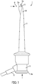
- Fig. 1 shows a schematic lateral side view of an endodontic file clip (1) in the open position according to a first embodiment.
- the endodontic file clip (1) is suitable for use with an apex locator.
- the first embodiment as shown in detail in Fig.
- the endodontic file clip (1) comprises: a hollow body (2); a push button (3) movably linked to the body (2); a spring (4) pushing the push button (3) away from the body (2); an electrically conductive hook (5) movably arranged within the body (2) and partly protruding out of the tip (2a) of the body (2) and fixed to the push button (3) to securely attach an endodontic file (6) to the tip (2a) when the push button (3) is released towards the closed position ( Fig.2A ), and disengage from the endodontic file (6) when the push button (3) is pressed towards the open position ( Fig. 1 ).
- the hook (5) is connected to the cable (8).
- Fig. 3 the hook (5) is connected to the cable (8).
- the endodontic file clip (1) further comprises: a detachment mechanism (7) for re-attachably detaching the push button (3), the spring (4) and the hook (5) from the body (2) for cleaning and disinfection in a dental washer disinfector.
- the detachment mechanism (7) comprises a detachment slot (2c) in the body (2) near the tip (2a), to allow manual detachment of the push button (3), the spring (4) and the hook (5) from the body (2) when the hook (5) is manually moved into the detachment slot (2c). Thereafter the push button (3) can be slid out of the body (2) together with the spring (4) and the hook (5) fixed thereto.
- a detachment mechanism (7) for re-attachably detaching the push button (3), the spring (4) and the hook (5) from the body (2) for cleaning and disinfection in a dental washer disinfector.
- the detachment mechanism (7) comprises a detachment slot (2c) in the body (2) near the tip (2a), to allow manual det
- the detachment slot (2c) is at the back portion (2d) of the body (2), averted from the u-shaped portion (5a) of the hook (5).
- the hook (5) is tiltable ( Fig. 5A ) for alignment with the detachment slot (2c).
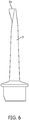
- Fig. 6 shows the body (2) after being detached from the push button (3), the spring (4) and the hook (5) for cleaning and disinfection.
- Fig. 7 shows the hook (5), the spring (4), the push button (3) and the cable (8) of the endodontic file clip (1) after being detached from the body (2) for cleaning and disinfection.
- the endodontic file clip (1) has a first security mechanism (9) which blocks the detachment mechanism (7) when the push button (3) is in the closed position ( Fig. 2A ) and unblocks the detachment mechanism (7) when the push button (3) is in the open position ( Fig. 5A ).
- the first security mechanism (9) is configured through a notch (2b) which is formed into the body (2) near the tip (2a), and a u-shaped portion (5a) which is formed at the protruding end of the hook (5).
- the u-shaped portion (5a) becomes attached to the notch (2b) when the push button (3) is in the closed position and becomes detached from the notch (2b) when the push button (3) is in the open position.
- Fig. 8 shows a rear side view of an endodontic file clip according to a second embodiment.
- the endodontic file clip (1) has a second security mechanism (10) which is configured through a window portion (2g) that is formed into the detachment slot (2c) and a key portion (5b) that is formed onto the hook (5).
- the key portion (5b) is wider than the detachment slot (2c) and matches the window portion (2g) for passage.
- the push button (3) has two depression levels such that when the push button (3) is at the first depression level ( Fig.
- the endodontic file (6) can be disengaged from the hook (5), but the key portion (5b) stays short of clearance from detachment slot (2c) at the tip (2a), and thus the second security mechanism (10) blocks the detachment mechanism (7), particularly the second security mechanism (10) blocks manual tilting movement of the hook (5) into the detachment slot (2c).
- the second security mechanism (10) blocks the detachment mechanism (7), particularly the second security mechanism (10) blocks manual tilting movement of the hook (5) into the detachment slot (2c).
- the second security mechanism (10) unblocks the detachment mechanism (7), particularly the second security mechanism (10) unblocks the manual tilting movement of the hook (5), and the hook (5) can be freely tilted/flexed through the detachment slot (2c).
- the endodontic file clip (1) has also a third security mechanism (11) which is configured by the push button (3) which has the two depression levels but no collar (3b). As shown in Fig. 8 , when push button (3) is at the first depression level then it becomes flush with the lower part of the body (2). And as shown in Fig.9 , the user can further press the collarless push button (3) by using an attachment clip or a pencil.
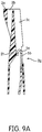
- FIG. 9A shows the interior of the hollow body (2).
- the hollow body (2) is optionally provided with a ramp (2h) for guiding the key portion (5b) through the window portion (2g) during reassembly.
- Fig. 10 shows a schematic top view of an endodontic file clip (1) in the closed position according to a third embodiment.
- the detachment slot (2c') is at the lateral portion (2e) of the body (2).
- the hook (5) is rotatable for alignment with the detachment slot (2c').
- the front face of the push button (3) comprises a slot (3c) for a screwdriver to facilitate rotation of the push button (3) during attachment or detachment.
- the push button (3) has a cam groove (3a).
- the body (2) has a cam pin (2f) for engaging with the cam groove (3a) respectively.
- the push button (3a) can be pressed, rotated by a predetermined angle, preferably 90 degrees and released for alignment with the detachment slot (2c').
- the endodontic file (6) can be disengaged from the hook (5) when the push button (3) is pressed to the open position.
- endodontic file clip (1) has an alternative second security mechanism (10').
- the depth of the cam groove (3a) has been increased also to have a two-depression level push button (3).
- the alternative second security system (10') is configured through the cam groove (3a) formed in the push button (2), and the cam pin (2f) formed into the body (2).
- the endodontic file (6) can be disengaged from the hook (5), but the cam pin (2f) stays short of clearance from the vertical portion of the cam groove (3a) and cannot be rotated unless pressed further to the second depression level.
- the hook (5) can be freely rotated along the horizontal portion of the cam groove (3a) to get aligned with the detachment slot (2c') as shown in Fig.11 . Thereafter the push button (3) can be slid out of the body (2) together with the spring (4) and the hook (5) fixed thereto.
Landscapes
- Health & Medical Sciences (AREA)
- Life Sciences & Earth Sciences (AREA)
- Engineering & Computer Science (AREA)
- Biomedical Technology (AREA)
- Biophysics (AREA)
- Oral & Maxillofacial Surgery (AREA)
- Dentistry (AREA)
- Epidemiology (AREA)
- Animal Behavior & Ethology (AREA)
- General Health & Medical Sciences (AREA)
- Public Health (AREA)
- Veterinary Medicine (AREA)
- Dental Tools And Instruments Or Auxiliary Dental Instruments (AREA)
Abstract
Description
- The present invention relates to an endodontic file clip for attachment to an endodontic file and for use with an apex locator to determine the length of the dental root canal to be treated.
- Root canal treatment also known as endodontic treatment, involves the removal of the infected dental pulp such as nerves, blood vessels and other cellular tissues from the tooth. Endodontic files are used to remove the infected pulp particularly from the root canal of the tooth. The root canals generally vary in length. Therefore, the position of the endodontic file relative to the tooth apex must be precisely determined. The tooth has an electrical impedance which can be measured with an electronical measurement device commonly known as an apex locator. The use of the apex locator during the endodontic treatment requires a closed electrical circuit which can be established through a couple of electrodes including a first electrode known as the lip clip which is attachable to the lip and a second electrode known as the endodontic file clip which is attachable to the endodontic file. The electrical impedance between the lip clip and the endodontic file changes with the increase of the endodontic file engagement inside the root canal located between the root canal entry and the apical constriction. The endodontic file clip is generally provided as a separate device which can be connected to the apex locator through a cable.
-
JP2012019849A - Endodontic file clips are contaminated during patient treatment with pulp tissue and saliva. For meeting the hygienic requirements, the endodontic file clip must be disinfected before re-use. However, the prior art endodontic file clips are generally made up of several components with close interfaces and narrow gaps. These make a time-consuming manual cleaning unavoidable.
- An objective of the present invention is to overcome the disadvantages of the prior art and provide an endodontic file clip which is easy to use in endodontic treatment and which can be disassembled after use for cleaning and disinfection in a dental washer disinfector, be sterilized and reassembled for re-use.
- These objectives are achieved through the endodontic file clip as defined in
claim 1. The subject-matters of the dependent claims relate to further developments. - The endodontic file clip of the present invention is suitable for use with an apex locator. The endodontic file clip comprises a hollow body; a push button movably linked to the body; a spring pushing the push button away from the body; an electrically conductive hook movably arranged within the body and partly protruding out of the tip of the body and fixed to the push button to securely attach an endodontic file to the tip when the push button is released towards the closed position, and disengage from the endodontic file when the push button is pressed towards the open position. The endodontic file clip further comprises: a detachment mechanism for re-attachably detaching the push button, the spring and the hook from the body for cleaning and disinfection in a dental washer disinfector.
- A major advantageous effect of the present invention is that the endodontic file clip can be disassembled for cleaning and disinfection. Once disassembled, each of the components can be easily and quickly cleaned and disinfected. The cleaning and disinfection can be made manually or automatically in a dental washer disinfector. Since all surfaces of the disassembled endodontic file are fully visible, the removal of the pulp tissue and saliva can be visually verified after the cleaning and the disinfection has been completed.
- According to the present invention the endodontic file clip may be optionally provided with at least one security mechanism (hereinafter the first security mechanism) for preventing unintentional or accidental disassembly of the components, namely of the push button, the spring, the hook, and the body during endodontic treatment when the push button is in the closed position. The first security mechanism blocks the detachment mechanism when the push button is in the closed position and unblocks the detachment mechanism when the push button is in the open position. To use the detachment mechanism the optional first security mechanism must be unlocked. In an embodiment of the first security mechanism, the hook is provided with a u-shaped portion that becomes attached to a notch in the body near the tip when the push button is moved to the closed position. In the closed position, the endodontic file is securely attached by the u-shaped portion of the hook to the tip. When the push button is moved to the open position, the u-shaped portion of the hook becomes detached from the notch i.e., the first security mechanism becomes unlocked, then the endodontic file can also be freely detached from the hook, and, if desired, the endodontic file clip can be further disassembled through the detachment mechanism unless not blocked through a further optional security mechanism (hereinafter the second optional security mechanism) which will be introduced as next. Thereby, a more secure operation of the endodontic file clip can be achieved during or after the endodontic treatment.
- According to the present invention the endodontic file clip may be optionally provided with a further security mechanism i.e., the second security mechanism for preventing unintentional or accidental disassembly of the components during endodontic treatment when the push button is in the open position for engaging/disengaging the endodontic file. To use the detachment mechanism the optional second security mechanism must be unlocked. In an embodiment of the second security mechanism, the push button has two depression levels. When the push button is at the first depression level corresponding to the open position, the endodontic file can be engaged with or disengaged from the hook, but the second security mechanism blocks the detachment mechanism, and when the push button is further pressed to the second depression level beyond the open position, the second security mechanism becomes unlocked, and the second security mechanism unblocks the detachment mechanism.
- According to the present invention, in an embodiment of the detachment mechanism, the body is provided with a detachment slot near the tip to allow manual detachment of the push button, the spring and the hook from the body (hereinafter detachment operation). To initiate the detachment operation, the optional first security mechanism and the optional second security mechanism must be each unlocked, then the hook must be manually moved into the detachment slot. Thereafter, the push button can be relatively slid out of the body together with the spring and the hook fixed thereto. When the push button is at the first depression level corresponding to the open position, the endodontic file can be disengaged from the hook, but the optional second security mechanism blocks manual movement of the hook into the detachment slot, and when the push button is further pressed to the second depression level then the second security mechanism unblocks manual movement of the hook and the hook can be freely moved into the detachment slot.
- The detachment slot may be formed into various portions of the body. In a version of this embodiment, the detachment slot is at the back portion of the body. And the hook can be moved into the detachment slot by tilting/flexing the same. In an alternative version of this embodiment, the detachment slot is at the lateral portion of the body. And the hook can be moved into the slot by rotating the same, preferably through 90 degrees. For facilitating the rotation of the hook during the detachment operation, the front face of the push button is optionally provided with a screw driver slot or a protruding grip. In a further version of this embodiment, the detachment slot is optionally further provided with a window portion whereas the hook is further provided with a key portion which is wider than the detachment slot and which matches the window portion. The key portion can pass through the window portion during the detachment operation. The interior of the hollow body is optionally provided with a ramp-like guiding portion for guiding the key portion through the window portion during reassembly. When the push button is pressed to the first depression level, the hook can be disengaged from the endodontic file, but the key portion stays short of clearance from the tip, and thus the hook cannot be moved i.e., tilted into the detachment slot unless the push button is further pressed to the second depression level. When the push button is further pressed to the second depression level, the hook can be freely tilted through the detachment slot i.e., the second security mechanism becomes unlocked and thus the push button, the spring and the hook can be detached from the body. Thereby, a more secure operation of the endodontic file clip can be achieved during or after the endodontic treatment. In a further alternative version of this embodiment, the push button is further optionally provided with bayonet type u-shaped cam groove whereas the body is further provided with a cam pin matching the u-shaped cam groove. Alternatively, the respective positions of cam pin and the cam groove may be interchanged. The depth of the cam groove may be pre-adjusted to have a single or a two-level depression push button. In the latter case, when the push button is pressed to the first depression level, the hook can be disengaged from the endodontic file, but the cam pin stays short of clearance from the vertical portion of the cam groove, and thus the hook cannot be moved i.e., rotated into the detachment slot unless the push button is further pressed to the second depression level. When the push button is further pressed to the second depression level, the cam pin can be rotated in the horizontal portion of the cam groove i.e., the second security mechanism becomes unlocked and the hook can be freely rotated to get aligned with the detachment slot, and thus the push button, the spring and the hook can be detached through the only open end of the cam groove from the body. Thereby, a more secure operation of the endodontic file clip can be achieved during or after the endodontic treatment.
- According to the present invention the endodontic file clip is optionally provided with a further security mechanism (hereinafter the third security mechanism) for preventing unintentional or accidental disassembly of the components when the push button is in the open position. Therefore, in an embodiment of the third security mechanism, the two-level push button has no collar, namely it is provided without a collar. When the push button is pressed to the first depression level then it becomes flush with the lower part of body. When the push button is further pressed to the second level then the push button is deep inside the body. However, since the depression region inside the body is small compared to the finger, the user must preferably utilize a paper clip, a pencil, or the like to press the push button deep into the body until the second depression level is reached. Thereby, a more secure operation of the endodontic file clip can be achieved during or after the endodontic treatment.
- In the subsequent description, the present invention will be described in more detail by using exemplary embodiments and by referring to the drawings, wherein
-
Fig. 1 - is a schematic lateral side view of an endodontic file clip in the open position according to a first embodiment of the present invention; -
Fig. 2A - is a schematic lateral side view of the endodontic file clip ofFig. 1 in the closed position; -
Fig. 2B - is a schematic vertical cross-sectional view of the endodontic file clip ofFig 2A ; -
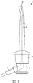
Fig. 3 - is a schematic lateral side view of the endodontic file clip ofFig. 1 , wherein the dotted lines show the hook and the cable; -
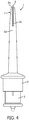
Fig. 4 - is a schematic rear side view of the endodontic file clip ofFig. 1 , wherein a detachment slot is formed in the back portion of the body; -
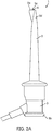
Fig. 5A - is a schematic lateral side view of the endodontic file clip ofFig. 1 , wherein the push button, the hook, the spring and the cable are being detached from the body; -
Fig. 5B - is a schematic cross-sectional view of the endodontic file clip ofFig. 5A ; -
Fig. 6 - is a schematic lateral side view of the body of the endodontic file clip ofFig. 1 ; -
Fig. 7 - is a schematic lateral side view of the push button, the hook, the spring and the cable of the endodontic file clip ofFig. 1 ; -
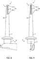
Fig. 8 - is a schematic rear side view of an endodontic file clip according to a second embodiment of the present invention having a two-level push button, wherein the push button is pressed to the first depression level; -
Fig. 9 - is another schematic rear side view of the endodontic file ofFig. 8 , wherein the push button is pressed to the second depression level; -
Fig. 9A - is a cross sectional schematic partial side view of the endodontic file ofFig. 9 during reassembly; -
Fig. 10 - is a schematic top view of an endodontic file clip in the closed position according to a third embodiment of the present invention; -
Fig. 11 - is a schematic top view of the endodontic file clip ofFig. 10 , wherein the hook has been counter clockwise rotated about 90 degrees to the detachment slot; -
Fig. 12 - is a schematic lateral side view of the endodontic file clip ofFig. 10 , before the hook is completely 90 degrees counter clockwise rotated to the detachment slot; -
Fig. 13 - is a schematic partial lateral side view of the push button, the hook, the spring, and the cable according to the third embodiment; -
Fig. 14 - is another schematic perspective view of the body of the endodontic file clip according to the third embodiment. - The reference numbers shown in the drawings denote the elements as listed below and will be referred to in the subsequent description of the exemplary embodiments.
- 1.
- Endodontic file clip
- 2.
- Body
2a. Tip
2b. Notch
2c. Detachment slot
2c' Detachment slot
2d. Back portion
2e. Lateral portion
2f. Cam pin
2g. Window portion
2h. Ramp - 3.
- Push button
3a. Cam groove
3b. Collar
3c. Screw driver slot - 4.
- Spring
- 5.
- Hook
5a. U-shaped portion
5b. Key portion - 6.
- Endodontic file
- 7.
- Detachment mechanism
- 8.
- Cable
- 9.
- First security mechanism
- 10.
- Second security mechanism
- 10'
- Second security mechanism
- 11.
- Third security mechanism
-
Fig. 1 shows a schematic lateral side view of an endodontic file clip (1) in the open position according to a first embodiment. The endodontic file clip (1) is suitable for use with an apex locator. In the first embodiment, as shown in detail inFig. 2B , the endodontic file clip (1) comprises: a hollow body (2); a push button (3) movably linked to the body (2); a spring (4) pushing the push button (3) away from the body (2); an electrically conductive hook (5) movably arranged within the body (2) and partly protruding out of the tip (2a) of the body (2) and fixed to the push button (3) to securely attach an endodontic file (6) to the tip (2a) when the push button (3) is released towards the closed position (Fig.2A ), and disengage from the endodontic file (6) when the push button (3) is pressed towards the open position (Fig. 1 ). As shown inFig. 3 , the hook (5) is connected to the cable (8). As shown inFig. 5A andFig.5B , the endodontic file clip (1) further comprises: a detachment mechanism (7) for re-attachably detaching the push button (3), the spring (4) and the hook (5) from the body (2) for cleaning and disinfection in a dental washer disinfector. As shown inFig. 5B , the detachment mechanism (7) comprises a detachment slot (2c) in the body (2) near the tip (2a), to allow manual detachment of the push button (3), the spring (4) and the hook (5) from the body (2) when the hook (5) is manually moved into the detachment slot (2c). Thereafter the push button (3) can be slid out of the body (2) together with the spring (4) and the hook (5) fixed thereto. As shown inFig. 4 , the detachment slot (2c) is at the back portion (2d) of the body (2), averted from the u-shaped portion (5a) of the hook (5). And the hook (5) is tiltable (Fig. 5A ) for alignment with the detachment slot (2c).Fig. 6 shows the body (2) after being detached from the push button (3), the spring (4) and the hook (5) for cleaning and disinfection.Fig. 7 shows the hook (5), the spring (4), the push button (3) and the cable (8) of the endodontic file clip (1) after being detached from the body (2) for cleaning and disinfection. As shown inFig. 2A andFig. 5A , the endodontic file clip (1) has a first security mechanism (9) which blocks the detachment mechanism (7) when the push button (3) is in the closed position (Fig. 2A ) and unblocks the detachment mechanism (7) when the push button (3) is in the open position (Fig. 5A ). As shown in more detail inFig. 2B , the first security mechanism (9) is configured through a notch (2b) which is formed into the body (2) near the tip (2a), and a u-shaped portion (5a) which is formed at the protruding end of the hook (5). The u-shaped portion (5a) becomes attached to the notch (2b) when the push button (3) is in the closed position and becomes detached from the notch (2b) when the push button (3) is in the open position. -
Fig. 8 shows a rear side view of an endodontic file clip according to a second embodiment. In the second embodiment, the endodontic file clip (1) has a second security mechanism (10) which is configured through a window portion (2g) that is formed into the detachment slot (2c) and a key portion (5b) that is formed onto the hook (5). The key portion (5b) is wider than the detachment slot (2c) and matches the window portion (2g) for passage. In the second embodiment, the push button (3) has two depression levels such that when the push button (3) is at the first depression level (Fig. 8 ) corresponding to the open position, the endodontic file (6) can be disengaged from the hook (5), but the key portion (5b) stays short of clearance from detachment slot (2c) at the tip (2a), and thus the second security mechanism (10) blocks the detachment mechanism (7), particularly the second security mechanism (10) blocks manual tilting movement of the hook (5) into the detachment slot (2c). As shown inFig.9 , when the push button (3) is further pressed to the second depression level beyond the open position, the second security mechanism (10) unblocks the detachment mechanism (7), particularly the second security mechanism (10) unblocks the manual tilting movement of the hook (5), and the hook (5) can be freely tilted/flexed through the detachment slot (2c). During the detachment operation the key portion (5b) is passed through the window portion (2g) as the push button (3) is slid out of the body (2) together with the spring (4) and the hook (5) fixed thereto. In the second embodiment, the endodontic file clip (1) has also a third security mechanism (11) which is configured by the push button (3) which has the two depression levels but no collar (3b). As shown inFig. 8 , when push button (3) is at the first depression level then it becomes flush with the lower part of the body (2). And as shown inFig.9 , the user can further press the collarless push button (3) by using an attachment clip or a pencil. When the push button (3) is further pressed to the second depression level then the push button (3) is deep inside the body (2), and the second security mechanism (10) is unlocked for allowing the manual detachment through detachment mechanism (7).Fig. 9A shows the interior of the hollow body (2). As shown inFig. 9A the hollow body (2) is optionally provided with a ramp (2h) for guiding the key portion (5b) through the window portion (2g) during reassembly. -
Fig. 10 shows a schematic top view of an endodontic file clip (1) in the closed position according to a third embodiment. In the third embodiment, as shown inFig. 12 , the detachment slot (2c') is at the lateral portion (2e) of the body (2). And the hook (5) is rotatable for alignment with the detachment slot (2c'). The front face of the push button (3) comprises a slot (3c) for a screwdriver to facilitate rotation of the push button (3) during attachment or detachment. As shown inFig. 13 , the push button (3) has a cam groove (3a). As shown inFig. 14 , the body (2) has a cam pin (2f) for engaging with the cam groove (3a) respectively. As shown inFig. 12 , the push button (3a) can be pressed, rotated by a predetermined angle, preferably 90 degrees and released for alignment with the detachment slot (2c'). The endodontic file (6) can be disengaged from the hook (5) when the push button (3) is pressed to the open position. In third embodiment, endodontic file clip (1) has an alternative second security mechanism (10'). And the depth of the cam groove (3a) has been increased also to have a two-depression level push button (3). As shown inFig. 13 andFig. 14 , the alternative second security system (10') is configured through the cam groove (3a) formed in the push button (2), and the cam pin (2f) formed into the body (2). When the push button (3) is at the first depression level then the endodontic file (6) can be disengaged from the hook (5), but the cam pin (2f) stays short of clearance from the vertical portion of the cam groove (3a) and cannot be rotated unless pressed further to the second depression level. When the push button (3) is further pressed to the second depression level then the hook (5) can be freely rotated along the horizontal portion of the cam groove (3a) to get aligned with the detachment slot (2c') as shown inFig.11 . Thereafter the push button (3) can be slid out of the body (2) together with the spring (4) and the hook (5) fixed thereto.
Claims (14)
- An endodontic file clip (1) for an apex locator, comprising:a hollow body (2);a push button (3) movably linked to the body (2);a spring (4) pushing the push button (3) away from the body (2);an electrically conductive hook (5) movably arranged within the body (2) and partly protruding out of the tip (2a) of the body (2) and fixed to the push button (3) to securely attach an endodontic file (6) to the tip (2a) when the push button (3) is released towards the closed position, and disengage from the endodontic file (6) when the push button (3) is pressed towards the open position;characterized by further comprising:
a detachment mechanism (7) for re-attachably detaching the push button (3), the spring (4) and the hook (5) from the body (2) for cleaning and disinfection in a dental washer disinfector. - The endodontic file clip (1) according to claim 1, characterized by further comprising: a first security mechanism (9), which blocks the detachment mechanism (7) when the push button (3) is in the closed position, and unblocks the detachment mechanism (7) when the push button (3) is in the open position.
- The endodontic file clip (1) according to claim 2, characterized in that the body (2) has a notch (2b) near the tip (2a); and the hook (5) has a u-shaped portion (5a) which is attached to the notch (2b) when the push button (3) is in the closed position, and is detached from the notch (2b) when the push button (3) is in the open position, wherein the notch (2b) and the u-shaped portion (5a) constitute the first security mechanism (9).
- The endodontic file clip (1) according to any one of claims 1 to 3, characterized by further comprising a second security mechanism (10,10'), wherein the push button (3) has two depression levels, and when the push button (3) is at the first depression level corresponding to the open position, the endodontic file (6) can be disengaged from the hook (5), and the second security mechanism (10,10') blocks the detachment mechanism (7), and when the push button (3) is further pressed to the second depression level beyond the open position, the second security mechanism (10,10') unblocks the detachment mechanism (7).
- The endodontic file clip (1) according to any one of claims 1 to 4, characterized in that the detachment mechanism (7) comprises a detachment slot (2c;2c') in the body (2) near the tip (2a), to allow manual detachment of the push button (3), the spring (4) and the hook (5) from the body (2) when the hook (5) is manually moved into the detachment slot (2c, 2c').
- The endodontic file clip (1) according to claim 5, characterized in that when the push button (3) is at the first depression level, the endodontic file (6) can be disengaged from the hook (5), and the second security mechanism (10, 10') blocks manual movement of the hook (5) into the detachment slot (2c, 2c'), and when the push button (3) is further pressed to the second depression level the second security mechanism (10,10') unblocks manual movement of the hook (5), and the hook (5) can be freely moved into the detachment slot (2c,2c').
- The endodontic file clip (1) according to claim 5 or 6, characterized in that the detachment slot (2c) is at the back portion (2d) of the body (2), averted from the u-shaped portion (5a) of the hook (5); and the hook (5) is manually tiltable for alignment with the detachment slot (2c).
- The endodontic file clip (1) according to claim 7, characterized in that the detachment slot (2c) comprises a window portion (2g); the hook (5) comprises a key portion (5b) wider than the detachment slot (2c) and matching the window portion (2g); and the push button (3) has two depression levels, when the push button (3) is at the first depression level the endodontic file (6) can be disengaged from the hook (5), and the key portion (5b) stays short of clearance from detachment slot (2c) at the tip (2a), and when the push button (3) is further pressed to the second depression level then the hook (5) can be freely tilted through the detachment slot (2c), wherein the window portion (2g) and the key portion (5b) constitute the second security mechanism (10).
- The endodontic file clip (1) according to claim 8, characterized in that the interior of the hollow body (2) is provided with a ramp (2h) for guiding the key portion (5b) through the window portion (2g) during reassembly.
- The endodontic file clip (1) according to claim 5 or 6, characterized in that the detachment slot (2c') is at the lateral portion (2e) of the body (2); and the hook (5) is manually rotatable for alignment with the detachment slot (2c').
- The endodontic file clip (1) according to claim 10, characterized in that the front face of the push button (3) comprises a slot (3c) for a screwdriver or a protruding grip to facilitate rotation of the push button (3) during attachment or detachment.
- The endodontic file clip (1) according to claim 10 or 11, characterized in that the push button (3) has either a cam groove (3a) or a cam pin; and the body (2) has a cam pin (2f) or a cam groove for respectively matching each other as the push button (3a) is pressed, rotated by a predetermined angle and released for alignment with the detachment slot (2c').
- The endodontic file clip (1) according to claim 12, the push button (3) has two depression levels, when the push button (3) is at the first depression level then the endodontic file (6) can be disengaged from the hook (5), and the cam pin (2f) stays short of clearance from a vertical portion of the cam groove (3a), and when the push button (3) is further pressed to the second depression level then the hook (5) can be freely rotated in a horizontal portion of the cam groove (3a) to get aligned with the detachment slot (2c'), wherein cam groove (3a) and the cam pin (2f) constitute the second security mechanism (10').
- The endodontic file clip (1) according to any one of claims 4 to 13, characterized by further comprising: a third security mechanism (11) which is constituted by the push button (3) that has the two depression levels, and that is further provided without a collar (3b), when push button (3) is pressed to the first depression level then it becomes flush with the lower part of the body (2), and when the push button (3) is further pressed to the second depression level then the push button (3) is deep inside the body (2).
Priority Applications (6)
| Application Number | Priority Date | Filing Date | Title |
|---|---|---|---|
| EP19174433.3A EP3738546B1 (en) | 2019-05-14 | 2019-05-14 | Endodontic file clip for an apex locator |
| JP2021541098A JP7571031B2 (en) | 2019-05-14 | 2020-05-14 | Endodontic File Clip for Apex Locator |
| EP20724850.1A EP3968896B1 (en) | 2019-05-14 | 2020-05-14 | Endodontic file clip for an apex locator |
| US17/610,231 US12390316B2 (en) | 2019-05-14 | 2020-05-14 | Endodontic file clip for an apex locator |
| PCT/EP2020/063443 WO2020229591A1 (en) | 2019-05-14 | 2020-05-14 | Endodontic file clip for an apex locator |
| CA3120798A CA3120798A1 (en) | 2019-05-14 | 2020-05-14 | Endodontic file clip for an apex locator |
Applications Claiming Priority (1)
| Application Number | Priority Date | Filing Date | Title |
|---|---|---|---|
| EP19174433.3A EP3738546B1 (en) | 2019-05-14 | 2019-05-14 | Endodontic file clip for an apex locator |
Publications (2)
| Publication Number | Publication Date |
|---|---|
| EP3738546A1 true EP3738546A1 (en) | 2020-11-18 |
| EP3738546B1 EP3738546B1 (en) | 2022-03-09 |
Family
ID=66542153
Family Applications (2)
| Application Number | Title | Priority Date | Filing Date |
|---|---|---|---|
| EP19174433.3A Active EP3738546B1 (en) | 2019-05-14 | 2019-05-14 | Endodontic file clip for an apex locator |
| EP20724850.1A Active EP3968896B1 (en) | 2019-05-14 | 2020-05-14 | Endodontic file clip for an apex locator |
Family Applications After (1)
| Application Number | Title | Priority Date | Filing Date |
|---|---|---|---|
| EP20724850.1A Active EP3968896B1 (en) | 2019-05-14 | 2020-05-14 | Endodontic file clip for an apex locator |
Country Status (5)
| Country | Link |
|---|---|
| US (1) | US12390316B2 (en) |
| EP (2) | EP3738546B1 (en) |
| JP (1) | JP7571031B2 (en) |
| CA (1) | CA3120798A1 (en) |
| WO (1) | WO2020229591A1 (en) |
Cited By (1)
| Publication number | Priority date | Publication date | Assignee | Title |
|---|---|---|---|---|
| US12390316B2 (en) | 2019-05-14 | 2025-08-19 | Dentsply Sirona Inc. | Endodontic file clip for an apex locator |
Citations (3)
| Publication number | Priority date | Publication date | Assignee | Title |
|---|---|---|---|---|
| JP2004000554A (en) * | 2002-04-26 | 2004-01-08 | Idm:Kk | Infection prevention implement for measuring length of root canal |
| CN101828976A (en) * | 2010-05-04 | 2010-09-15 | 深圳市龙成科技有限公司 | High temperature-resistant disinfected connecting line for measuring tooth root |
| JP2012019849A (en) | 2010-07-13 | 2012-02-02 | Osada Res Inst Ltd | Dental root canal length measuring instrument |
Family Cites Families (11)
| Publication number | Priority date | Publication date | Assignee | Title |
|---|---|---|---|---|
| US1945327A (en) * | 1932-06-30 | 1934-01-30 | Willis B Morse | Combined tongue depressor and electrode for electrocoagulation of tonsils |
| US4943290A (en) * | 1987-06-23 | 1990-07-24 | Concept Inc. | Electrolyte purging electrode tip |
| US5843020A (en) * | 1997-04-16 | 1998-12-01 | Irvine Biomedical, Inc. | Ablation device and methods |
| US20060154199A1 (en) * | 2005-01-07 | 2006-07-13 | Randall Maxwell | Wireless root canal apex locator |
| US7993138B2 (en) * | 2007-08-21 | 2011-08-09 | Buchanan L Stephen | Apex locator for endodontic procedures |
| JP2012024480A (en) * | 2010-07-27 | 2012-02-09 | Osada Res Inst Ltd | Root canal length measuring instrument |
| US20160143705A1 (en) * | 2014-11-21 | 2016-05-26 | David J. Clark | Methods and Devices for Treating Root Canals of Teeth |
| JP2020531118A (en) * | 2017-08-21 | 2020-11-05 | デンツプライ シロナ インコーポレイテッド | Root canal length measuring instrument |
| US12279808B2 (en) * | 2018-12-11 | 2025-04-22 | Neurent Medical Limited | Systems and methods for therapeutic nasal neuromodulation |
| EP3738546B1 (en) | 2019-05-14 | 2022-03-09 | DENTSPLY SIRONA Inc. | Endodontic file clip for an apex locator |
| USD940876S1 (en) * | 2019-11-14 | 2022-01-11 | Dentsply Sirona Inc. | Endodontic file clip for an apex locator |
-
2019
- 2019-05-14 EP EP19174433.3A patent/EP3738546B1/en active Active
-
2020
- 2020-05-14 CA CA3120798A patent/CA3120798A1/en active Pending
- 2020-05-14 US US17/610,231 patent/US12390316B2/en active Active
- 2020-05-14 WO PCT/EP2020/063443 patent/WO2020229591A1/en not_active Ceased
- 2020-05-14 JP JP2021541098A patent/JP7571031B2/en active Active
- 2020-05-14 EP EP20724850.1A patent/EP3968896B1/en active Active
Patent Citations (3)
| Publication number | Priority date | Publication date | Assignee | Title |
|---|---|---|---|---|
| JP2004000554A (en) * | 2002-04-26 | 2004-01-08 | Idm:Kk | Infection prevention implement for measuring length of root canal |
| CN101828976A (en) * | 2010-05-04 | 2010-09-15 | 深圳市龙成科技有限公司 | High temperature-resistant disinfected connecting line for measuring tooth root |
| JP2012019849A (en) | 2010-07-13 | 2012-02-02 | Osada Res Inst Ltd | Dental root canal length measuring instrument |
Cited By (1)
| Publication number | Priority date | Publication date | Assignee | Title |
|---|---|---|---|---|
| US12390316B2 (en) | 2019-05-14 | 2025-08-19 | Dentsply Sirona Inc. | Endodontic file clip for an apex locator |
Also Published As
| Publication number | Publication date |
|---|---|
| EP3968896A1 (en) | 2022-03-23 |
| US12390316B2 (en) | 2025-08-19 |
| US20220249216A1 (en) | 2022-08-11 |
| JP2022532693A (en) | 2022-07-19 |
| CA3120798A1 (en) | 2020-11-19 |
| WO2020229591A1 (en) | 2020-11-19 |
| EP3968896B1 (en) | 2023-09-27 |
| EP3738546B1 (en) | 2022-03-09 |
| JP7571031B2 (en) | 2024-10-22 |
Similar Documents
| Publication | Publication Date | Title |
|---|---|---|
| US7121827B2 (en) | Endodontic instrument | |
| DK148616B (en) | INFUSION NEEDLE UNIT | |
| DE602004024819D1 (en) | IMPROVED SURGICAL INSTRUMENT FOR THE TREATMENT OF HARNINE CONTINENCE | |
| EP3968896B1 (en) | Endodontic file clip for an apex locator | |
| AU6209298A (en) | Teeth-cleaning device with a handle | |
| US20100055641A1 (en) | Dental instrument for eliminating broken pieces using flexible guide plate | |
| US1628499A (en) | Dental appliance | |
| KR20120140028A (en) | Dental Functional Bite Blocks | |
| JP2023541433A5 (en) | ||
| US20180242996A1 (en) | Disposable surgical swing scalpel with reusable scissor action handle | |
| US10478218B2 (en) | Scalpel holder | |
| KR102828846B1 (en) | Cannula | |
| EP0994675B1 (en) | Protective cap for medical hf instruments | |
| KR101187636B1 (en) | Dental unit chair with automatic anesthesia apparatus | |
| EP3614961A1 (en) | Apex locator attachment | |
| CN101389281B (en) | Probe manipulator | |
| CN204909528U (en) | Trigeminal neuralgia professional retractor of performing operation | |
| WO2015080505A1 (en) | Gingival resection plier for implant | |
| US20210251722A1 (en) | Spacer for endodontic instrument | |
| CN212466219U (en) | Shifter for screwdriver and healing cap in mistaken swallowing and aspiration preventing implant system | |
| GB2203087A (en) | A scalpel | |
| AU5644596A (en) | Dental file/reamer instrument | |
| JP3555868B2 (en) | Dental intraoral vacuum handpiece | |
| KR200427313Y1 (en) | Dental Miller | |
| EP1543795A1 (en) | A single-use dispensing tip for a multiple-use dental material dispensing cartridge and dental material application system comprising such tip |
Legal Events
| Date | Code | Title | Description |
|---|---|---|---|
| PUAI | Public reference made under article 153(3) epc to a published international application that has entered the european phase |
Free format text: ORIGINAL CODE: 0009012 |
|
| STAA | Information on the status of an ep patent application or granted ep patent |
Free format text: STATUS: THE APPLICATION HAS BEEN PUBLISHED |
|
| AK | Designated contracting states |
Kind code of ref document: A1 Designated state(s): AL AT BE BG CH CY CZ DE DK EE ES FI FR GB GR HR HU IE IS IT LI LT LU LV MC MK MT NL NO PL PT RO RS SE SI SK SM TR |
|
| AX | Request for extension of the european patent |
Extension state: BA ME |
|
| STAA | Information on the status of an ep patent application or granted ep patent |
Free format text: STATUS: REQUEST FOR EXAMINATION WAS MADE |
|
| 17P | Request for examination filed |
Effective date: 20210427 |
|
| RBV | Designated contracting states (corrected) |
Designated state(s): AL AT BE BG CH CY CZ DE DK EE ES FI FR GB GR HR HU IE IS IT LI LT LU LV MC MK MT NL NO PL PT RO RS SE SI SK SM TR |
|
| GRAP | Despatch of communication of intention to grant a patent |
Free format text: ORIGINAL CODE: EPIDOSNIGR1 |
|
| STAA | Information on the status of an ep patent application or granted ep patent |
Free format text: STATUS: GRANT OF PATENT IS INTENDED |
|
| INTG | Intention to grant announced |
Effective date: 20210930 |
|
| GRAS | Grant fee paid |
Free format text: ORIGINAL CODE: EPIDOSNIGR3 |
|
| GRAA | (expected) grant |
Free format text: ORIGINAL CODE: 0009210 |
|
| STAA | Information on the status of an ep patent application or granted ep patent |
Free format text: STATUS: THE PATENT HAS BEEN GRANTED |
|
| AK | Designated contracting states |
Kind code of ref document: B1 Designated state(s): AL AT BE BG CH CY CZ DE DK EE ES FI FR GB GR HR HU IE IS IT LI LT LU LV MC MK MT NL NO PL PT RO RS SE SI SK SM TR |
|
| REG | Reference to a national code |
Ref country code: CH Ref legal event code: EP Ref country code: AT Ref legal event code: REF Ref document number: 1473520 Country of ref document: AT Kind code of ref document: T Effective date: 20220315 |
|
| REG | Reference to a national code |
Ref country code: DE Ref legal event code: R096 Ref document number: 602019012269 Country of ref document: DE |
|
| REG | Reference to a national code |
Ref country code: IE Ref legal event code: FG4D |
|
| REG | Reference to a national code |
Ref country code: SE Ref legal event code: TRGR |
|
| REG | Reference to a national code |
Ref country code: LT Ref legal event code: MG9D |
|
| REG | Reference to a national code |
Ref country code: NL Ref legal event code: MP Effective date: 20220309 |
|
| PG25 | Lapsed in a contracting state [announced via postgrant information from national office to epo] |
Ref country code: RS Free format text: LAPSE BECAUSE OF FAILURE TO SUBMIT A TRANSLATION OF THE DESCRIPTION OR TO PAY THE FEE WITHIN THE PRESCRIBED TIME-LIMIT Effective date: 20220309 Ref country code: NO Free format text: LAPSE BECAUSE OF FAILURE TO SUBMIT A TRANSLATION OF THE DESCRIPTION OR TO PAY THE FEE WITHIN THE PRESCRIBED TIME-LIMIT Effective date: 20220609 Ref country code: LT Free format text: LAPSE BECAUSE OF FAILURE TO SUBMIT A TRANSLATION OF THE DESCRIPTION OR TO PAY THE FEE WITHIN THE PRESCRIBED TIME-LIMIT Effective date: 20220309 Ref country code: HR Free format text: LAPSE BECAUSE OF FAILURE TO SUBMIT A TRANSLATION OF THE DESCRIPTION OR TO PAY THE FEE WITHIN THE PRESCRIBED TIME-LIMIT Effective date: 20220309 Ref country code: BG Free format text: LAPSE BECAUSE OF FAILURE TO SUBMIT A TRANSLATION OF THE DESCRIPTION OR TO PAY THE FEE WITHIN THE PRESCRIBED TIME-LIMIT Effective date: 20220609 |
|
| REG | Reference to a national code |
Ref country code: AT Ref legal event code: MK05 Ref document number: 1473520 Country of ref document: AT Kind code of ref document: T Effective date: 20220309 |
|
| PG25 | Lapsed in a contracting state [announced via postgrant information from national office to epo] |
Ref country code: LV Free format text: LAPSE BECAUSE OF FAILURE TO SUBMIT A TRANSLATION OF THE DESCRIPTION OR TO PAY THE FEE WITHIN THE PRESCRIBED TIME-LIMIT Effective date: 20220309 Ref country code: GR Free format text: LAPSE BECAUSE OF FAILURE TO SUBMIT A TRANSLATION OF THE DESCRIPTION OR TO PAY THE FEE WITHIN THE PRESCRIBED TIME-LIMIT Effective date: 20220610 Ref country code: FI Free format text: LAPSE BECAUSE OF FAILURE TO SUBMIT A TRANSLATION OF THE DESCRIPTION OR TO PAY THE FEE WITHIN THE PRESCRIBED TIME-LIMIT Effective date: 20220309 |
|
| PG25 | Lapsed in a contracting state [announced via postgrant information from national office to epo] |
Ref country code: NL Free format text: LAPSE BECAUSE OF FAILURE TO SUBMIT A TRANSLATION OF THE DESCRIPTION OR TO PAY THE FEE WITHIN THE PRESCRIBED TIME-LIMIT Effective date: 20220309 |
|
| PG25 | Lapsed in a contracting state [announced via postgrant information from national office to epo] |
Ref country code: SM Free format text: LAPSE BECAUSE OF FAILURE TO SUBMIT A TRANSLATION OF THE DESCRIPTION OR TO PAY THE FEE WITHIN THE PRESCRIBED TIME-LIMIT Effective date: 20220309 Ref country code: SK Free format text: LAPSE BECAUSE OF FAILURE TO SUBMIT A TRANSLATION OF THE DESCRIPTION OR TO PAY THE FEE WITHIN THE PRESCRIBED TIME-LIMIT Effective date: 20220309 Ref country code: RO Free format text: LAPSE BECAUSE OF FAILURE TO SUBMIT A TRANSLATION OF THE DESCRIPTION OR TO PAY THE FEE WITHIN THE PRESCRIBED TIME-LIMIT Effective date: 20220309 Ref country code: PT Free format text: LAPSE BECAUSE OF FAILURE TO SUBMIT A TRANSLATION OF THE DESCRIPTION OR TO PAY THE FEE WITHIN THE PRESCRIBED TIME-LIMIT Effective date: 20220711 Ref country code: ES Free format text: LAPSE BECAUSE OF FAILURE TO SUBMIT A TRANSLATION OF THE DESCRIPTION OR TO PAY THE FEE WITHIN THE PRESCRIBED TIME-LIMIT Effective date: 20220309 Ref country code: EE Free format text: LAPSE BECAUSE OF FAILURE TO SUBMIT A TRANSLATION OF THE DESCRIPTION OR TO PAY THE FEE WITHIN THE PRESCRIBED TIME-LIMIT Effective date: 20220309 Ref country code: CZ Free format text: LAPSE BECAUSE OF FAILURE TO SUBMIT A TRANSLATION OF THE DESCRIPTION OR TO PAY THE FEE WITHIN THE PRESCRIBED TIME-LIMIT Effective date: 20220309 Ref country code: AT Free format text: LAPSE BECAUSE OF FAILURE TO SUBMIT A TRANSLATION OF THE DESCRIPTION OR TO PAY THE FEE WITHIN THE PRESCRIBED TIME-LIMIT Effective date: 20220309 |
|
| PG25 | Lapsed in a contracting state [announced via postgrant information from national office to epo] |
Ref country code: PL Free format text: LAPSE BECAUSE OF FAILURE TO SUBMIT A TRANSLATION OF THE DESCRIPTION OR TO PAY THE FEE WITHIN THE PRESCRIBED TIME-LIMIT Effective date: 20220309 Ref country code: IS Free format text: LAPSE BECAUSE OF FAILURE TO SUBMIT A TRANSLATION OF THE DESCRIPTION OR TO PAY THE FEE WITHIN THE PRESCRIBED TIME-LIMIT Effective date: 20220709 Ref country code: AL Free format text: LAPSE BECAUSE OF FAILURE TO SUBMIT A TRANSLATION OF THE DESCRIPTION OR TO PAY THE FEE WITHIN THE PRESCRIBED TIME-LIMIT Effective date: 20220309 |
|
| REG | Reference to a national code |
Ref country code: DE Ref legal event code: R097 Ref document number: 602019012269 Country of ref document: DE |
|
| PLBE | No opposition filed within time limit |
Free format text: ORIGINAL CODE: 0009261 |
|
| STAA | Information on the status of an ep patent application or granted ep patent |
Free format text: STATUS: NO OPPOSITION FILED WITHIN TIME LIMIT |
|
| REG | Reference to a national code |
Ref country code: BE Ref legal event code: MM Effective date: 20220531 |
|
| PG25 | Lapsed in a contracting state [announced via postgrant information from national office to epo] |
Ref country code: MC Free format text: LAPSE BECAUSE OF FAILURE TO SUBMIT A TRANSLATION OF THE DESCRIPTION OR TO PAY THE FEE WITHIN THE PRESCRIBED TIME-LIMIT Effective date: 20220309 Ref country code: LU Free format text: LAPSE BECAUSE OF NON-PAYMENT OF DUE FEES Effective date: 20220514 Ref country code: DK Free format text: LAPSE BECAUSE OF FAILURE TO SUBMIT A TRANSLATION OF THE DESCRIPTION OR TO PAY THE FEE WITHIN THE PRESCRIBED TIME-LIMIT Effective date: 20220309 |
|
| 26N | No opposition filed |
Effective date: 20221212 |
|
| PG25 | Lapsed in a contracting state [announced via postgrant information from national office to epo] |
Ref country code: SI Free format text: LAPSE BECAUSE OF FAILURE TO SUBMIT A TRANSLATION OF THE DESCRIPTION OR TO PAY THE FEE WITHIN THE PRESCRIBED TIME-LIMIT Effective date: 20220309 |
|
| PG25 | Lapsed in a contracting state [announced via postgrant information from national office to epo] |
Ref country code: IE Free format text: LAPSE BECAUSE OF NON-PAYMENT OF DUE FEES Effective date: 20220514 |
|
| PG25 | Lapsed in a contracting state [announced via postgrant information from national office to epo] |
Ref country code: BE Free format text: LAPSE BECAUSE OF NON-PAYMENT OF DUE FEES Effective date: 20220531 |
|
| PG25 | Lapsed in a contracting state [announced via postgrant information from national office to epo] |
Ref country code: MK Free format text: LAPSE BECAUSE OF FAILURE TO SUBMIT A TRANSLATION OF THE DESCRIPTION OR TO PAY THE FEE WITHIN THE PRESCRIBED TIME-LIMIT Effective date: 20220309 Ref country code: CY Free format text: LAPSE BECAUSE OF FAILURE TO SUBMIT A TRANSLATION OF THE DESCRIPTION OR TO PAY THE FEE WITHIN THE PRESCRIBED TIME-LIMIT Effective date: 20220309 |
|
| PG25 | Lapsed in a contracting state [announced via postgrant information from national office to epo] |
Ref country code: HU Free format text: LAPSE BECAUSE OF FAILURE TO SUBMIT A TRANSLATION OF THE DESCRIPTION OR TO PAY THE FEE WITHIN THE PRESCRIBED TIME-LIMIT; INVALID AB INITIO Effective date: 20190514 |
|
| PG25 | Lapsed in a contracting state [announced via postgrant information from national office to epo] |
Ref country code: TR Free format text: LAPSE BECAUSE OF FAILURE TO SUBMIT A TRANSLATION OF THE DESCRIPTION OR TO PAY THE FEE WITHIN THE PRESCRIBED TIME-LIMIT Effective date: 20220309 |
|
| PG25 | Lapsed in a contracting state [announced via postgrant information from national office to epo] |
Ref country code: MT Free format text: LAPSE BECAUSE OF FAILURE TO SUBMIT A TRANSLATION OF THE DESCRIPTION OR TO PAY THE FEE WITHIN THE PRESCRIBED TIME-LIMIT Effective date: 20220309 |
|
| P01 | Opt-out of the competence of the unified patent court (upc) registered |
Free format text: CASE NUMBER: UPC_APP_413139/2023 Effective date: 20230509 |
|
| PGFP | Annual fee paid to national office [announced via postgrant information from national office to epo] |
Ref country code: DE Payment date: 20250423 Year of fee payment: 7 |
|
| PGFP | Annual fee paid to national office [announced via postgrant information from national office to epo] |
Ref country code: GB Payment date: 20250423 Year of fee payment: 7 |
|
| PGFP | Annual fee paid to national office [announced via postgrant information from national office to epo] |
Ref country code: IT Payment date: 20250423 Year of fee payment: 7 |
|
| PGFP | Annual fee paid to national office [announced via postgrant information from national office to epo] |
Ref country code: FR Payment date: 20250423 Year of fee payment: 7 |
|
| PGFP | Annual fee paid to national office [announced via postgrant information from national office to epo] |
Ref country code: CH Payment date: 20250601 Year of fee payment: 7 |
|
| PGFP | Annual fee paid to national office [announced via postgrant information from national office to epo] |
Ref country code: SE Payment date: 20250423 Year of fee payment: 7 |