EP3738471A1 - Drawer and furniture fittings thereof - Google Patents
Drawer and furniture fittings thereof Download PDFInfo
- Publication number
- EP3738471A1 EP3738471A1 EP19204038.4A EP19204038A EP3738471A1 EP 3738471 A1 EP3738471 A1 EP 3738471A1 EP 19204038 A EP19204038 A EP 19204038A EP 3738471 A1 EP3738471 A1 EP 3738471A1
- Authority
- EP
- European Patent Office
- Prior art keywords
- wall
- mounting device
- section
- furniture fittings
- drawer
- Prior art date
- Legal status (The legal status is an assumption and is not a legal conclusion. Google has not performed a legal analysis and makes no representation as to the accuracy of the status listed.)
- Granted
Links
Images





Classifications
-
- A—HUMAN NECESSITIES
- A47—FURNITURE; DOMESTIC ARTICLES OR APPLIANCES; COFFEE MILLS; SPICE MILLS; SUCTION CLEANERS IN GENERAL
- A47B—TABLES; DESKS; OFFICE FURNITURE; CABINETS; DRAWERS; GENERAL DETAILS OF FURNITURE
- A47B88/00—Drawers for tables, cabinets or like furniture; Guides for drawers
- A47B88/90—Constructional details of drawers
- A47B88/944—Drawers characterised by the front panel
- A47B88/95—Drawers characterised by the front panel characterised by connection means for the front panel
-
- A—HUMAN NECESSITIES
- A47—FURNITURE; DOMESTIC ARTICLES OR APPLIANCES; COFFEE MILLS; SPICE MILLS; SUCTION CLEANERS IN GENERAL
- A47B—TABLES; DESKS; OFFICE FURNITURE; CABINETS; DRAWERS; GENERAL DETAILS OF FURNITURE
- A47B88/00—Drawers for tables, cabinets or like furniture; Guides for drawers
- A47B88/90—Constructional details of drawers
- A47B88/941—Drawers being constructed from two or more parts
-
- A—HUMAN NECESSITIES
- A47—FURNITURE; DOMESTIC ARTICLES OR APPLIANCES; COFFEE MILLS; SPICE MILLS; SUCTION CLEANERS IN GENERAL
- A47B—TABLES; DESKS; OFFICE FURNITURE; CABINETS; DRAWERS; GENERAL DETAILS OF FURNITURE
- A47B88/00—Drawers for tables, cabinets or like furniture; Guides for drawers
- A47B88/90—Constructional details of drawers
- A47B88/944—Drawers characterised by the front panel
-
- A—HUMAN NECESSITIES
- A47—FURNITURE; DOMESTIC ARTICLES OR APPLIANCES; COFFEE MILLS; SPICE MILLS; SUCTION CLEANERS IN GENERAL
- A47B—TABLES; DESKS; OFFICE FURNITURE; CABINETS; DRAWERS; GENERAL DETAILS OF FURNITURE
- A47B88/00—Drawers for tables, cabinets or like furniture; Guides for drawers
- A47B88/90—Constructional details of drawers
- A47B88/944—Drawers characterised by the front panel
- A47B88/95—Drawers characterised by the front panel characterised by connection means for the front panel
- A47B2088/951—Drawers characterised by the front panel characterised by connection means for the front panel having male and female interlocking parts
-
- A—HUMAN NECESSITIES
- A47—FURNITURE; DOMESTIC ARTICLES OR APPLIANCES; COFFEE MILLS; SPICE MILLS; SUCTION CLEANERS IN GENERAL
- A47B—TABLES; DESKS; OFFICE FURNITURE; CABINETS; DRAWERS; GENERAL DETAILS OF FURNITURE
- A47B88/00—Drawers for tables, cabinets or like furniture; Guides for drawers
- A47B88/90—Constructional details of drawers
- A47B88/944—Drawers characterised by the front panel
- A47B88/95—Drawers characterised by the front panel characterised by connection means for the front panel
- A47B2088/952—Drawers characterised by the front panel characterised by connection means for the front panel having two parts and using a screw
Definitions
- the present invention relates to a drawer and its furniture fittings. More particularly, the invention relates to a technique by which a wall of a drawer and a mounting device of the drawer can be connected without using tools.
- US Published Patent Application No. 2014/0225493 A1 discloses a piece of furniture that includes a plurality of drawers whose front panels are of the same type.
- the front panel of each drawer is connected to the lateral walls of the drawer through the fittings on the front panel.
- each front panel includes a plurality of screws in addition to the fittings, and the fittings cannot be fixed on the front panel without using a screwdriver to tighten the screws.
- the furniture disclosed in the aforesaid patent application uses a mounting means that entails locking screws to a front panel in order to fix the corresponding fittings on the front panel. During the assembly process, however, tool operation tends to inconvenience an assembly worker.
- the present invention relates to a drawer and its furniture fittings.
- the drawer includes a wall and a mounting device that are connected in a tool-free manner.
- a set of furniture fittings include a first wall, a second wall, and a mounting device.
- the second wall is provided with a first structure
- the mounting device is provided with a second structure.
- the first structure and the second structure are detachably engaged with each other in a tool-free manner.
- the second wall is mounted on the first wall via the mounting device.
- the set of furniture fittings further include a connection device disposed on the first wall.
- the connection device is configured to connect with the mounting device.
- the mounting device includes a pin
- the connection device includes a fastening member configured to be fastened to the pin
- the first wall is a sidewall of a drawer
- the second wall is the front panel of the drawer.
- the second wall includes a first portion, a second portion, and a middle portion connected between the first portion and the second portion, and either the first portion or the second portion is provided with the first structure.
- one of the first structure and the second structure includes at least one projection
- the other of the first structure and the second structure includes at least one hole configured to work with the at least one projection
- the at least one projection has a first section and a second section bent with respect to the first section, wherein the first section and the second section are configured to be inserted into the at least one hole and engage with the hole wall of the at least one hole.
- one of the second wall and the mounting device includes a second projection, wherein the second projection includes an elastic section and a supporting section connected to the elastic section, the supporting section being configured to support the other of the second wall and the mounting device.
- the first portion and/or the second portion is threadedly connected to the middle portion.
- the first portion and/or the second portion includes a plate body and a connecting section, wherein the connecting section is substantially perpendicularly connected to the plate body and is connected to a lateral side of the middle portion via a screw.
- a drawer includes a bottom panel, a pair of first walls, a rear wall, a second wall, and at least one mounting device.
- the pair of first walls are disposed adjacent to two lateral sides of the bottom panel respectively.
- the rear wall is disposed adjacent to a rear side of the bottom panel.
- the second wall is disposed adjacent to a front side of the bottom panel and is provided with at least one first structure.
- Each of the at least one mounting device is provided with a second structure.
- the at least one second structure of the at least one mounting device is engaged with the at least one first structure of the second wall in a tool-free manner.
- the second wall is mounted on at least one of the pair of first walls via the at least one mounting device.
- the drawer 20 includes a bottom panel 22, a pair of first walls 24, a rear wall 26, and a second wall 28.
- the foregoing components can be viewed as furniture fittings before they are put together to form the drawer 20.
- the pair of first walls 24 are disposed adjacent to the two lateral sides (e.g., the left side and the right side) of the bottom panel 22 respectively.
- the rear wall 26 is disposed adjacent to the rear side of the bottom panel 22, and the second wall 28 is disposed adjacent to the front side of the bottom panel 22.
- the second wall 28 is mounted on the connection device 32 on one of the first walls 24 in a detachable manner through a mounting device 30.
- the second wall 28 is provided with a pair of mounting devices 30, and each of the first walls 24 is provided with a connection device 32, wherein each mounting device 30 is configured to be mounted on the corresponding connection device 32 in a detachable manner; in other words, each connection device 32 is configured to connect with the corresponding mounting device 30.
- each mounting device 30 includes a pin 30a
- each connection device 32 includes a fastening member 32a with a fastening portion 32b.
- the fastening portion 32b of each fastening member 32a is configured to be fastened to the corresponding pin 30a securely.
- the pair of first walls 24 are the sidewalls of the drawer 20, and the second wall 28 is the front panel of the drawer 20.
- the second wall 28 includes a first portion 28a, a second portion 28b, and a middle portion 28c.
- the middle portion 28c is connected between the first portion 28a and the second portion 28b.
- the first portion 28a and the second portion 28b are threadedly connected to the two lateral sides (e.g., the left side and the right side) of the middle portion 28c respectively.
- the first portion 28a and the second portion 28b have substantially the same structural configuration.
- both the first portion 28a and the second portion 28b include a plate body 34 and a connecting section 36, wherein the connecting section 36 is substantially perpendicularly connected to the plate body 34 and is connected to a lateral side of the middle portion 28c through a screw 38.
- the plate body 34 of the second portion 28b of the second wall 28 is provided with a first structure 40, and the corresponding mounting device 30 is provided with a second structure 42.
- the second structure 42 is configured to engage with the first structure 40 of the second wall 28.
- one of the first structure 40 and the second structure 42 includes at least one first projection 40a
- the other of the first structure 40 and the second structure 42 includes at least one hole 42a configured to work with the at least one first projection 40a.
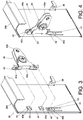
- FIG. 3 and FIG. 4 show two first projections 40a and two holes 42a, the following description is directed to only one of the first projections 40a and the corresponding hole 42a for the sake of brevity, and the present invention has no limitation on the number of the at least one first projection 40a or the at least one hole 42a.
- the first projection 40a in this embodiment has a first section S1 and a second section S2 bent with respect to the first section S1.
- the second section S2 is bent in such a way that it is substantially perpendicular to the first section S1.
- one of the second wall 28 and the mounting device 30 e.g., the second wall 28
- the second projection 40b includes an elastic section Y1 and a supporting section Y2 connected to the elastic section Y1.
- the elastic section Y1 is raised at an angle with respect to the plane in which the plate body 34 of the second wall 28 lies.
- the plate body 34 of the second wall 28 has an opening 41 corresponding in position to the second projection 40b.
- FIG. 5 to FIG. 7 schematically show the process of mounting the mounting device 30 on the second wall 28 (rather than the other way around) for illustrative purposes only.
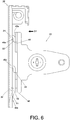
- the mounting device 30 is moved toward the second wall 28 in a first direction D1, with the hole 42a of the mounting device 30 in alignment with the first projection 40a of the second wall 28 (see FIG. 5 and FIG. 6 ).
- the elastic section Y1 of the second projection 40b of the second wall 28 generates an elastic force due to the pressure applied by the mounting device 30 to the elastic section Y1.
- the elastic section Y1 of the second projection 40b of the second wall 28 releases the elastic force and thereby brings the supporting section Y2 of the second projection 40b of the second wall 28 to a position where the supporting section Y2 props the mounting device 30 up to ensure that the mounting device 30 is mounted securely on the second wall 28.
- the second direction D2 is substantially perpendicular to the first direction D1.
- the first section S1 and the second section S2 of the first projection 40a of the second wall 28 are engaged with the hole wall 44 of the hole 42a of the mounting device 30 (see FIG. 7 ) to prevent the mounting device 30 from being displaced in the second direction D2 with respect to the second wall 28.
- the supporting section Y2 of the second projection 40b supports the other of the second wall 28 and the mounting device 30, e.g., supports a portion 46 of the mounting device 30 (see FIG. 7 ) to keep the mounting device 30 from being displaced in the opposite direction of the second direction D2 (hereinafter referred to as the third direction D3) with respect to the second wall 28.
- the engagement between the first structure 40 and the second structure 42 allows the mounting device 30 to be connected securely to the second wall 28.
- a user can mount the mounting device 30 securely on the second wall 28 without using any tool, and the second wall 28, therefore, can be mounted securely on the connection device 32 of the corresponding first wall 24 through the mounting device 30.
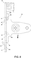
- a user can apply a force F to the elastic section Y1 of the second projection 40b (see FIG. 7 ) to tilt the elastic section Y1 by an angle with respect to the plane in which the plate body 34 of the second wall 28 lies, and once the elastic section Y1 is so tilted, the supporting section Y2 ceases to support the portion 46 of the mounting device 30 (see FIG. 8 ).
- the mounting device 30 in this state can be displaced in the third direction D3 (i.e., the opposite direction of the second direction D2) with respect to the second wall 28 (see FIG.
- the bottom panel 22, the pair of first walls 24, the rear wall 26, and the second wall 28 of the drawer 20 jointly define a space.
- the first portion 28a and the second portion 28b of the second wall 28 are connected to the two lateral sides of the middle portion 28c respectively in a threaded manner (see FIG. 2 ).
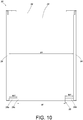
- the middle portion 28c in this embodiment has a standard width W, and a user may choose a first portion 28a and a second portion 28b of a first predetermined width W1 in order for the total width of the second wall 28 (mathematically expressed as W+2W1) to match a first width XI defined by the pair of first walls 24.
- the bottom panel 202, the pair of first walls 204, the rear wall 206, and the second wall 208 of the drawer 200 jointly define a space.
- the first portion 210 and the second portion 212 of the second wall 208 are connected to the two lateral sides of the middle portion 214 respectively in the aforesaid threaded manner.
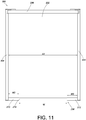
- the middle portion 214 in this embodiment also has the standard width W, and a user may choose a first portion 210 and a second portion 212 of a second predetermined width W2 in order for the total width of the second wall 208 (mathematically expressed as W+2W2) to match a second width X2 defined by the pair of first walls 204.
Landscapes
- Drawers Of Furniture (AREA)
- Connection Of Plates (AREA)
- Furniture Connections (AREA)
Abstract
Description
- The present invention relates to a drawer and its furniture fittings. More particularly, the invention relates to a technique by which a wall of a drawer and a mounting device of the drawer can be connected without using tools.
-
US Published Patent Application No. 2014/0225493 A1 discloses a piece of furniture that includes a plurality of drawers whose front panels are of the same type. The front panel of each drawer is connected to the lateral walls of the drawer through the fittings on the front panel. More specifically, each front panel includes a plurality of screws in addition to the fittings, and the fittings cannot be fixed on the front panel without using a screwdriver to tighten the screws. - The furniture disclosed in the aforesaid patent application uses a mounting means that entails locking screws to a front panel in order to fix the corresponding fittings on the front panel. During the assembly process, however, tool operation tends to inconvenience an assembly worker.
- The present invention relates to a drawer and its furniture fittings. The drawer includes a wall and a mounting device that are connected in a tool-free manner.
- According to one aspect of the present invention, a set of furniture fittings include a first wall, a second wall, and a mounting device. The second wall is provided with a first structure, and the mounting device is provided with a second structure. The first structure and the second structure are detachably engaged with each other in a tool-free manner. The second wall is mounted on the first wall via the mounting device.
- Preferably, the set of furniture fittings further include a connection device disposed on the first wall. The connection device is configured to connect with the mounting device.
- Preferably, the mounting device includes a pin, and the connection device includes a fastening member configured to be fastened to the pin.
- Preferably, the first wall is a sidewall of a drawer, and the second wall is the front panel of the drawer.
- Preferably, the second wall includes a first portion, a second portion, and a middle portion connected between the first portion and the second portion, and either the first portion or the second portion is provided with the first structure.
- Preferably, one of the first structure and the second structure includes at least one projection, and the other of the first structure and the second structure includes at least one hole configured to work with the at least one projection.
- Preferably, the at least one projection has a first section and a second section bent with respect to the first section, wherein the first section and the second section are configured to be inserted into the at least one hole and engage with the hole wall of the at least one hole.
- Preferably, one of the second wall and the mounting device includes a second projection, wherein the second projection includes an elastic section and a supporting section connected to the elastic section, the supporting section being configured to support the other of the second wall and the mounting device.
- Preferably, the first portion and/or the second portion is threadedly connected to the middle portion.
- Preferably, the first portion and/or the second portion includes a plate body and a connecting section, wherein the connecting section is substantially perpendicularly connected to the plate body and is connected to a lateral side of the middle portion via a screw.
- According to another aspect of the present invention, a drawer includes a bottom panel, a pair of first walls, a rear wall, a second wall, and at least one mounting device. The pair of first walls are disposed adjacent to two lateral sides of the bottom panel respectively. The rear wall is disposed adjacent to a rear side of the bottom panel. The second wall is disposed adjacent to a front side of the bottom panel and is provided with at least one first structure. Each of the at least one mounting device is provided with a second structure. The at least one second structure of the at least one mounting device is engaged with the at least one first structure of the second wall in a tool-free manner. The second wall is mounted on at least one of the pair of first walls via the at least one mounting device.
-
-
FIG. 1 is a perspective view of the drawer according to an embodiment of the present invention; -
FIG. 2 is an exploded perspective view of the drawer according to the embodiment of the present invention, showing the second wall detached from the main body of the drawer; -
FIG. 3 is an exploded perspective view of a portion of the second wall of the drawer and a mounting device of the drawer according to the embodiment of the present invention; -
FIG. 4 is an assembled perspective view of the portion of the second wall and the mounting device according to the embodiment of the present invention; -
FIG. 5 is an exploded schematic view of the portion of the second wall and the mounting device according to the embodiment of the present invention; -
FIG. 6 is a schematic view showing how the mounting device is mounted on the portion of the second wall according to the embodiment of the present invention; -
FIG. 7 is a schematic view in which the mounting device is mounted on the portion of the second wall according to the embodiment of the present invention; -
FIG. 8 is a schematic view showing how the mounting device is detached from the portion of the second wall according to the embodiment of the present invention; -
FIG. 9 is a schematic view in which the mounting device is detached from the portion of the second wall according to the embodiment of the present invention; -
FIG. 10 is a schematic view showing that the second wall of the drawer matches a first drawer width according to the embodiment of the present invention; and -
FIG. 11 is a schematic view showing that the second wall of the drawer matches a second drawer width according to another embodiment of the present invention. - Referring to
FIG. 1 andFIG. 2 , thedrawer 20 according to an embodiment of the present invention includes abottom panel 22, a pair offirst walls 24, arear wall 26, and asecond wall 28. The foregoing components can be viewed as furniture fittings before they are put together to form thedrawer 20. - The pair of
first walls 24 are disposed adjacent to the two lateral sides (e.g., the left side and the right side) of thebottom panel 22 respectively. Therear wall 26 is disposed adjacent to the rear side of thebottom panel 22, and thesecond wall 28 is disposed adjacent to the front side of thebottom panel 22. Thesecond wall 28 is mounted on theconnection device 32 on one of thefirst walls 24 in a detachable manner through amounting device 30. Preferably, thesecond wall 28 is provided with a pair ofmounting devices 30, and each of thefirst walls 24 is provided with aconnection device 32, wherein eachmounting device 30 is configured to be mounted on thecorresponding connection device 32 in a detachable manner; in other words, eachconnection device 32 is configured to connect with thecorresponding mounting device 30. Preferably, eachmounting device 30 includes apin 30a, and eachconnection device 32 includes afastening member 32a with afastening portion 32b. Thefastening portion 32b of eachfastening member 32a is configured to be fastened to thecorresponding pin 30a securely. - More specifically, the pair of
first walls 24 are the sidewalls of thedrawer 20, and thesecond wall 28 is the front panel of thedrawer 20. Thesecond wall 28 includes afirst portion 28a, asecond portion 28b, and amiddle portion 28c. Themiddle portion 28c is connected between thefirst portion 28a and thesecond portion 28b. Preferably, thefirst portion 28a and thesecond portion 28b are threadedly connected to the two lateral sides (e.g., the left side and the right side) of themiddle portion 28c respectively. Thefirst portion 28a and thesecond portion 28b have substantially the same structural configuration. For example, both thefirst portion 28a and thesecond portion 28b include aplate body 34 and a connectingsection 36, wherein the connectingsection 36 is substantially perpendicularly connected to theplate body 34 and is connected to a lateral side of themiddle portion 28c through ascrew 38. - Referring to
FIG. 3 and FIG. 4 , theplate body 34 of thesecond portion 28b of thesecond wall 28 is provided with afirst structure 40, and thecorresponding mounting device 30 is provided with asecond structure 42. Thesecond structure 42 is configured to engage with thefirst structure 40 of thesecond wall 28. - Preferably, one of the
first structure 40 and thesecond structure 42 includes at least onefirst projection 40a, and the other of thefirst structure 40 and thesecond structure 42 includes at least onehole 42a configured to work with the at least onefirst projection 40a. WhileFIG. 3 and FIG. 4 show twofirst projections 40a and twoholes 42a, the following description is directed to only one of thefirst projections 40a and thecorresponding hole 42a for the sake of brevity, and the present invention has no limitation on the number of the at least onefirst projection 40a or the at least onehole 42a. Thefirst projection 40a in this embodiment has a first section S1 and a second section S2 bent with respect to the first section S1. Preferably, the second section S2 is bent in such a way that it is substantially perpendicular to the first section S1. Preferably, one of thesecond wall 28 and the mounting device 30 (e.g., the second wall 28) includes asecond projection 40b, and thesecond projection 40b includes an elastic section Y1 and a supporting section Y2 connected to the elastic section Y1. Here, and by way of example only, the elastic section Y1 is raised at an angle with respect to the plane in which theplate body 34 of thesecond wall 28 lies. Preferably, theplate body 34 of thesecond wall 28 has anopening 41 corresponding in position to thesecond projection 40b. - Referring to
FIG. 5 ,FIG. 6 , andFIG. 7 , thesecond wall 28 and the mountingdevice 30 can be mounted on each other in a detachable manner.FIG. 5 to FIG. 7 schematically show the process of mounting the mountingdevice 30 on the second wall 28 (rather than the other way around) for illustrative purposes only. - To begin with, the mounting
device 30 is moved toward thesecond wall 28 in a first direction D1, with thehole 42a of the mountingdevice 30 in alignment with thefirst projection 40a of the second wall 28 (seeFIG. 5 andFIG. 6 ). - Once the first section S1 of the
first projection 40a of thesecond wall 28 is received in thehole 42a of the mountingdevice 30, the elastic section Y1 of thesecond projection 40b of thesecond wall 28 generates an elastic force due to the pressure applied by the mountingdevice 30 to the elastic section Y1. When the mountingdevice 30 is subsequently moved in a second direction D2 with respect to the second wall 28 (seeFIG. 7 ), the elastic section Y1 of thesecond projection 40b of thesecond wall 28 releases the elastic force and thereby brings the supporting section Y2 of thesecond projection 40b of thesecond wall 28 to a position where the supporting section Y2 props the mountingdevice 30 up to ensure that the mountingdevice 30 is mounted securely on thesecond wall 28. The second direction D2 is substantially perpendicular to the first direction D1. - More specifically, when the mounting
device 30 is mounted on thesecond wall 28, the first section S1 and the second section S2 of thefirst projection 40a of thesecond wall 28 are engaged with thehole wall 44 of thehole 42a of the mounting device 30 (seeFIG. 7 ) to prevent the mountingdevice 30 from being displaced in the second direction D2 with respect to thesecond wall 28. In the meantime, the supporting section Y2 of thesecond projection 40b supports the other of thesecond wall 28 and the mountingdevice 30, e.g., supports aportion 46 of the mounting device 30 (seeFIG. 7 ) to keep the mountingdevice 30 from being displaced in the opposite direction of the second direction D2 (hereinafter referred to as the third direction D3) with respect to thesecond wall 28. - Thus, the engagement between the
first structure 40 and thesecond structure 42 allows the mountingdevice 30 to be connected securely to thesecond wall 28. Moreover, thanks to the cooperation between thefirst structure 40 and thesecond structure 42, a user can mount the mountingdevice 30 securely on thesecond wall 28 without using any tool, and thesecond wall 28, therefore, can be mounted securely on theconnection device 32 of the correspondingfirst wall 24 through the mountingdevice 30. - When it is desired to detach the mounting
device 30 from thesecond wall 28, referring toFIG. 7 ,FIG. 8 , andFIG. 9 , a user can apply a force F to the elastic section Y1 of thesecond projection 40b (seeFIG. 7 ) to tilt the elastic section Y1 by an angle with respect to the plane in which theplate body 34 of thesecond wall 28 lies, and once the elastic section Y1 is so tilted, the supporting section Y2 ceases to support theportion 46 of the mounting device 30 (seeFIG. 8 ). The mountingdevice 30 in this state can be displaced in the third direction D3 (i.e., the opposite direction of the second direction D2) with respect to the second wall 28 (seeFIG. 8 ), thereby disengaging thehole wall 44 of thehole 42a of the mountingdevice 30 from the first section S1 and the second section S2 of thefirst projection 40a of the second wall 28 (seeFIG. 9 ), allowing the mountingdevice 30 to be detached from thesecond wall 28. - Referring to
FIG. 10 , thebottom panel 22, the pair offirst walls 24, therear wall 26, and thesecond wall 28 of thedrawer 20 jointly define a space. Thefirst portion 28a and thesecond portion 28b of thesecond wall 28 are connected to the two lateral sides of themiddle portion 28c respectively in a threaded manner (seeFIG. 2 ). Themiddle portion 28c in this embodiment has a standard width W, and a user may choose afirst portion 28a and asecond portion 28b of a first predetermined width W1 in order for the total width of the second wall 28 (mathematically expressed as W+2W1) to match a first width XI defined by the pair offirst walls 24. - In another embodiment as shown in
FIG. 11 , thebottom panel 202, the pair offirst walls 204, therear wall 206, and thesecond wall 208 of thedrawer 200 jointly define a space. Thefirst portion 210 and thesecond portion 212 of thesecond wall 208 are connected to the two lateral sides of themiddle portion 214 respectively in the aforesaid threaded manner. Themiddle portion 214 in this embodiment also has the standard width W, and a user may choose afirst portion 210 and asecond portion 212 of a second predetermined width W2 in order for the total width of the second wall 208 (mathematically expressed as W+2W2) to match a second width X2 defined by the pair offirst walls 204. - It can be known from the above that the foregoing embodiments of the present invention have the following features:
- 1. A user can mount the mounting
device 30 on thesecond wall 28 without using tools. This tool-free mounting design helps reduce cost or allows the furniture fittings to be assembled and disassembled with ease. - 2. Through the mounting
device 30, thesecond wall 28 can be mounted on theconnection device 32 of the correspondingfirst wall 24 in a detachable manner. - 3. As the
first portion 28a/210 and thesecond portion 28b/212 of thesecond wall 28/208 are respectively and threadedly connected to the two lateral sides of themiddle portion 28c/214, a user may choose and connect afirst portion 28a/210 and asecond portion 28b/212 of a certain predetermined width W1/W2 to the two lateral sides of themiddle portion 28c/214 respectively, in order for the resultingsecond wall 28/208 to match the width defined by the pair offirst walls 24/204 of thedrawer 20/200. - While the present invention has been disclosed through the preferred embodiments described above, those embodiments are not intended to be restrictive of the scope of the invention. The scope of patent protection sought by the applicant is defined by the appended claims.
Claims (12)
- A set of furniture fittings, comprising:a first wall (24, 204);a second wall (28, 208) provided with a first structure (40); anda mounting device (30) provided with a second structure (42);characterized inthat the first structure (40) and the second structure (42) are detachably engaged with each other in a tool-free manner, andthat the second wall (28, 208) is mounted on the first wall (24, 204) through the mounting device (30).
- The set of furniture fittings as claimed in claim 1, further comprising a connection device (32) disposed on the first wall (24, 204), wherein the connection device (32) is configured to connect with the mounting device (30).
- The set of furniture fittings as claimed in claim 2, wherein the mounting device (30) includes a pin (30a), and the connection device (32) includes a fastening member (32a) configured to be fastened to the pin (30a).
- The set of furniture fittings as claimed in any of claims 1-3, wherein the first wall (24, 204) is a sidewall of a drawer (20, 200), and the second wall (28, 208) is a front panel of the drawer (20, 200).
- The set of furniture fittings as claimed in any of claims 1-4, wherein the second wall (28, 208) includes a first portion (28a, 210), a second portion (28b, 212), and a middle portion (28c, 214) connected between the first portion (28a, 210) and the second portion (28b, 212), and at least one of the first portion (28a, 210) and the second portion (28b, 212) is provided with the first structure (40).
- The set of furniture fittings as claimed in claim 5, wherein at least one of the first portion (28a, 210) and the second portion (28b, 212) is threadedly connected to the middle portion (28c, 214).
- The set of furniture fittings as claimed in claim 5 or 6, wherein at least one of the first portion (28a, 210) and the second portion (28b, 212) includes a plate body (34) and a connecting section (36) substantially perpendicularly connected to the plate body (34), and the connecting section (36) is connected to a lateral side of the middle portion (28c, 214) through a screw (38).
- The set of furniture fittings as claimed in any of claims 1-7, wherein one of the first structure (40) and the second structure (42) includes a first projection (40a), and the other of the first structure (40) and the second structure (42) includes a hole (42a) configured to work with the first projection (40a).
- The set of furniture fittings as claimed in claim 8, wherein the first projection (40a) has a first section (S1) and a second section (S2) bent with respect to the first section (S1), and the first section (S1) and the second section (S2) are configured to be inserted into the hole (42a) and engage with a hole wall (44) of the hole (42a).
- The set of furniture fittings as claimed in any of claims 1-9, wherein one of the second wall (28, 208) and the mounting device (30) includes a second projection (40b), the second projection (40b) includes an elastic section (Y1) and a supporting section (Y2) connected to the elastic section (Y1), and the supporting section (Y2) is configured to support the other of the second wall (28, 208) and the mounting device (30).
- A drawer (20, 200), comprising:a bottom panel (22, 202);a rear wall (26, 206) disposed adjacent to a rear side of the bottom panel (22, 202); andthe set of furniture fittings according to any of claims 1-10,wherein the set of furniture fittings includes a pair of said first walls (24, 204), the pair of said first walls (24, 204) being disposed adjacent to two lateral sides of the bottom panel (22, 202) respectively,wherein the second wall (28, 208) of the set of furniture fittings is disposed adjacent to a front side of the bottom panel (22, 202) and provided with at least one said first structure (40), andwherein the set of furniture fittings includes at least one said mounting device (30) so that the second structure (42) of the at least one said mounting device (30) is engaged with the at least one said first structure (40) of the second wall (28, 208) in a tool-free manner, and that the second wall (28, 208) is mounted on at least one of the pair of said first walls (24, 204) through the at least one said mounting device (30).
- The drawer (20, 200) as claimed in claim 11, wherein the set of furniture fittings includes at least one said connection device (32) disposed on at least one of the pair of said first walls (24, 204).
Applications Claiming Priority (1)
| Application Number | Priority Date | Filing Date | Title |
|---|---|---|---|
| TW108117030A TWI698199B (en) | 2019-05-15 | 2019-05-15 | Drawer and furniture fittings thereof |
Publications (2)
| Publication Number | Publication Date |
|---|---|
| EP3738471A1 true EP3738471A1 (en) | 2020-11-18 |
| EP3738471B1 EP3738471B1 (en) | 2023-07-19 |
Family
ID=68296088
Family Applications (1)
| Application Number | Title | Priority Date | Filing Date |
|---|---|---|---|
| EP19204038.4A Active EP3738471B1 (en) | 2019-05-15 | 2019-10-18 | Drawer and furniture fittings thereof |
Country Status (4)
| Country | Link |
|---|---|
| US (1) | US10881204B2 (en) |
| EP (1) | EP3738471B1 (en) |
| JP (1) | JP6817396B2 (en) |
| TW (1) | TWI698199B (en) |
Families Citing this family (4)
| Publication number | Priority date | Publication date | Assignee | Title |
|---|---|---|---|---|
| US11266240B2 (en) * | 2019-09-26 | 2022-03-08 | Liberty Hardware Mfg. Corp. | Drawer assembly |
| TWI712381B (en) * | 2020-02-25 | 2020-12-11 | 川湖科技股份有限公司 | Mounting device and mounting method for furniture assembly |
| DE102022208433A1 (en) * | 2022-08-12 | 2024-02-15 | Blanco Gmbh + Co Kg | Mounting device, cover system and pull-out system |
| WO2025163779A1 (en) * | 2024-01-31 | 2025-08-07 | Ykk株式会社 | Connecting implement and connecting structure |
Citations (5)
| Publication number | Priority date | Publication date | Assignee | Title |
|---|---|---|---|---|
| EP0698357A1 (en) * | 1994-08-26 | 1996-02-28 | Julius Blum Gesellschaft m.b.H. | Fitting for furniture, especially connector |
| US5823650A (en) * | 1997-03-28 | 1998-10-20 | Lin; Tsung Lung | Drawer assembly |
| US5895103A (en) * | 1995-10-30 | 1999-04-20 | Julius Blum Gesellschaft M.B.H. | Fastening device for a front plate of a drawer |
| DE112009000135A5 (en) * | 2008-03-10 | 2011-04-14 | Julius Blum Gmbh | Drawer with a fastening device for wall elements |
| US20140225493A1 (en) | 2011-09-23 | 2014-08-14 | Ikea Supply Ag | Piece of furniture |
Family Cites Families (17)
| Publication number | Priority date | Publication date | Assignee | Title |
|---|---|---|---|---|
| US3610720A (en) * | 1969-08-27 | 1971-10-05 | Freedman Artcraft Engineering | Drawer construction |
| US3752553A (en) * | 1971-07-29 | 1973-08-14 | Amerock Corp | Drawer with snap-on front panel |
| US4042288A (en) * | 1972-12-08 | 1977-08-16 | L. B. (Plastics) Limited | Extruded plastic panel drawers |
| US3933402A (en) * | 1974-07-15 | 1976-01-20 | Joerns Furniture Company | Drawer with removable front panel |
| US4913580A (en) * | 1989-02-23 | 1990-04-03 | Suncast Corporation | Releasable connector assembly |
| DE9310206U1 (en) * | 1993-07-12 | 1993-10-14 | Grass AG, Höchst, Vorarlberg | Fastening device for connecting drawer parts |
| ES2188603T3 (en) * | 1994-01-17 | 2003-07-01 | Blum Gmbh Julius | HARDWARE FOR THE SETTING OF A REAR WALL OF A DRAWER TO COMPONENT ELEMENTS OF THE DRAWER. |
| US6419333B2 (en) * | 1997-10-02 | 2002-07-16 | Haworth, Inc. | Knock-down vertical file |
| US6409293B1 (en) * | 2001-07-24 | 2002-06-25 | Ching-Chang Chang | Cabinet and drawer assembly structure |
| TWM250597U (en) * | 2003-10-18 | 2004-11-21 | King Slide Works Co Ltd | Assembly component for side plate and face plate of drawer and structure thereof |
| MY150010A (en) * | 2006-01-09 | 2013-11-15 | Harn Marketing Sdn Bhd | Drawer assembly |
| AT510779B1 (en) | 2010-11-23 | 2014-09-15 | Blum Gmbh Julius | FURNITURE FITTING FOR FRONT PANEL MOUNTING |
| AT510781B1 (en) | 2010-11-23 | 2014-08-15 | Blum Gmbh Julius | FURNITURE FITTING FOR FRONT PANEL MOUNTING |
| DE102011050157A1 (en) * | 2011-05-06 | 2012-11-08 | Paul Hettich Gmbh & Co. Kg | drawer |
| AT511905B1 (en) * | 2011-08-30 | 2014-08-15 | Blum Gmbh Julius | DRAWER |
| EP3232860B1 (en) * | 2014-11-14 | 2019-10-02 | Inter IKEA Systems B.V. | Improved furniture piece comprising roller wheel assembly |
| DE102015110560A1 (en) * | 2015-07-01 | 2017-01-05 | Form Orange Produktentwicklung | Drawer with a base plate, two side walls, a rear wall and a panel |
-
2019
- 2019-05-15 TW TW108117030A patent/TWI698199B/en active
- 2019-09-11 US US16/567,329 patent/US10881204B2/en active Active
- 2019-10-08 JP JP2019184890A patent/JP6817396B2/en active Active
- 2019-10-18 EP EP19204038.4A patent/EP3738471B1/en active Active
Patent Citations (5)
| Publication number | Priority date | Publication date | Assignee | Title |
|---|---|---|---|---|
| EP0698357A1 (en) * | 1994-08-26 | 1996-02-28 | Julius Blum Gesellschaft m.b.H. | Fitting for furniture, especially connector |
| US5895103A (en) * | 1995-10-30 | 1999-04-20 | Julius Blum Gesellschaft M.B.H. | Fastening device for a front plate of a drawer |
| US5823650A (en) * | 1997-03-28 | 1998-10-20 | Lin; Tsung Lung | Drawer assembly |
| DE112009000135A5 (en) * | 2008-03-10 | 2011-04-14 | Julius Blum Gmbh | Drawer with a fastening device for wall elements |
| US20140225493A1 (en) | 2011-09-23 | 2014-08-14 | Ikea Supply Ag | Piece of furniture |
Also Published As
| Publication number | Publication date |
|---|---|
| EP3738471B1 (en) | 2023-07-19 |
| US20200359791A1 (en) | 2020-11-19 |
| JP2020186813A (en) | 2020-11-19 |
| TWI698199B (en) | 2020-07-11 |
| TW202042711A (en) | 2020-12-01 |
| JP6817396B2 (en) | 2021-01-20 |
| US10881204B2 (en) | 2021-01-05 |
Similar Documents
| Publication | Publication Date | Title |
|---|---|---|
| EP3738471B1 (en) | Drawer and furniture fittings thereof | |
| EP3905865B1 (en) | Slide rail assembly | |
| CN104900150B (en) | The connection structure and display screen of display screen | |
| CA3038058C (en) | Adjustable modular shelving system | |
| EP3167756A1 (en) | Quick-release mechanism for drawer slide parts | |
| EP3153065A1 (en) | Mounting part for slide rail assembly | |
| EP3168483B1 (en) | Drawer part assembly and mounting fitting thereof | |
| KR20150126357A (en) | Multi-part locking component, and sliding door | |
| US7429090B2 (en) | Attachment device for drawer front panels | |
| US9568140B2 (en) | Adapter plate for connecting two monitors to an arm mount | |
| US9750346B2 (en) | Drawer slide assembly | |
| JP5534639B2 (en) | desk | |
| EP3136694B1 (en) | Housing mounting mechanism for portable electronic device | |
| EP4427633A1 (en) | Furniture system and furniture assembly thereof | |
| TWI712381B (en) | Mounting device and mounting method for furniture assembly | |
| CN107872939A (en) | Sliding rail installation accessory assembly for rack | |
| CN111972890B (en) | Drawers and their furniture accessories | |
| US11448248B2 (en) | Panel mounted glass bracket assembly | |
| EP3167758B1 (en) | Drawer sidewall assembly | |
| CN110985505A (en) | Device for attaching a furniture part to a wall | |
| CN102900188B (en) | Pre-tightening connecting assembly used for mounting curtain wallboard | |
| JPS5922520A (en) | Platform equipped with card guide movable by side slide guide | |
| KR200494140Y1 (en) | Guide rail installation module free of disassembling tool | |
| EP4427635B1 (en) | Furniture system and furniture assembly thereof | |
| CN217644833U (en) | Drawer panel assembly and integrated stove |
Legal Events
| Date | Code | Title | Description |
|---|---|---|---|
| PUAI | Public reference made under article 153(3) epc to a published international application that has entered the european phase |
Free format text: ORIGINAL CODE: 0009012 |
|
| STAA | Information on the status of an ep patent application or granted ep patent |
Free format text: STATUS: REQUEST FOR EXAMINATION WAS MADE |
|
| 17P | Request for examination filed |
Effective date: 20200331 |
|
| AK | Designated contracting states |
Kind code of ref document: A1 Designated state(s): AL AT BE BG CH CY CZ DE DK EE ES FI FR GB GR HR HU IE IS IT LI LT LU LV MC MK MT NL NO PL PT RO RS SE SI SK SM TR |
|
| AX | Request for extension of the european patent |
Extension state: BA ME |
|
| STAA | Information on the status of an ep patent application or granted ep patent |
Free format text: STATUS: EXAMINATION IS IN PROGRESS |
|
| 17Q | First examination report despatched |
Effective date: 20210208 |
|
| GRAP | Despatch of communication of intention to grant a patent |
Free format text: ORIGINAL CODE: EPIDOSNIGR1 |
|
| STAA | Information on the status of an ep patent application or granted ep patent |
Free format text: STATUS: GRANT OF PATENT IS INTENDED |
|
| INTG | Intention to grant announced |
Effective date: 20230216 |
|
| GRAS | Grant fee paid |
Free format text: ORIGINAL CODE: EPIDOSNIGR3 |
|
| GRAA | (expected) grant |
Free format text: ORIGINAL CODE: 0009210 |
|
| STAA | Information on the status of an ep patent application or granted ep patent |
Free format text: STATUS: THE PATENT HAS BEEN GRANTED |
|
| AK | Designated contracting states |
Kind code of ref document: B1 Designated state(s): AL AT BE BG CH CY CZ DE DK EE ES FI FR GB GR HR HU IE IS IT LI LT LU LV MC MK MT NL NO PL PT RO RS SE SI SK SM TR |
|
| REG | Reference to a national code |
Ref country code: GB Ref legal event code: FG4D |
|
| REG | Reference to a national code |
Ref country code: CH Ref legal event code: EP |
|
| REG | Reference to a national code |
Ref country code: DE Ref legal event code: R096 Ref document number: 602019032922 Country of ref document: DE |
|
| REG | Reference to a national code |
Ref country code: IE Ref legal event code: FG4D |
|
| REG | Reference to a national code |
Ref country code: LT Ref legal event code: MG9D |
|
| REG | Reference to a national code |
Ref country code: NL Ref legal event code: MP Effective date: 20230719 |
|
| REG | Reference to a national code |
Ref country code: AT Ref legal event code: MK05 Ref document number: 1588564 Country of ref document: AT Kind code of ref document: T Effective date: 20230719 |
|
| PG25 | Lapsed in a contracting state [announced via postgrant information from national office to epo] |
Ref country code: NL Free format text: LAPSE BECAUSE OF FAILURE TO SUBMIT A TRANSLATION OF THE DESCRIPTION OR TO PAY THE FEE WITHIN THE PRESCRIBED TIME-LIMIT Effective date: 20230719 |
|
| PG25 | Lapsed in a contracting state [announced via postgrant information from national office to epo] |
Ref country code: GR Free format text: LAPSE BECAUSE OF FAILURE TO SUBMIT A TRANSLATION OF THE DESCRIPTION OR TO PAY THE FEE WITHIN THE PRESCRIBED TIME-LIMIT Effective date: 20231020 |
|
| PG25 | Lapsed in a contracting state [announced via postgrant information from national office to epo] |
Ref country code: IS Free format text: LAPSE BECAUSE OF FAILURE TO SUBMIT A TRANSLATION OF THE DESCRIPTION OR TO PAY THE FEE WITHIN THE PRESCRIBED TIME-LIMIT Effective date: 20231119 |
|
| PG25 | Lapsed in a contracting state [announced via postgrant information from national office to epo] |
Ref country code: SE Free format text: LAPSE BECAUSE OF FAILURE TO SUBMIT A TRANSLATION OF THE DESCRIPTION OR TO PAY THE FEE WITHIN THE PRESCRIBED TIME-LIMIT Effective date: 20230719 Ref country code: RS Free format text: LAPSE BECAUSE OF FAILURE TO SUBMIT A TRANSLATION OF THE DESCRIPTION OR TO PAY THE FEE WITHIN THE PRESCRIBED TIME-LIMIT Effective date: 20230719 Ref country code: PT Free format text: LAPSE BECAUSE OF FAILURE TO SUBMIT A TRANSLATION OF THE DESCRIPTION OR TO PAY THE FEE WITHIN THE PRESCRIBED TIME-LIMIT Effective date: 20231120 Ref country code: NO Free format text: LAPSE BECAUSE OF FAILURE TO SUBMIT A TRANSLATION OF THE DESCRIPTION OR TO PAY THE FEE WITHIN THE PRESCRIBED TIME-LIMIT Effective date: 20231019 Ref country code: LV Free format text: LAPSE BECAUSE OF FAILURE TO SUBMIT A TRANSLATION OF THE DESCRIPTION OR TO PAY THE FEE WITHIN THE PRESCRIBED TIME-LIMIT Effective date: 20230719 Ref country code: LT Free format text: LAPSE BECAUSE OF FAILURE TO SUBMIT A TRANSLATION OF THE DESCRIPTION OR TO PAY THE FEE WITHIN THE PRESCRIBED TIME-LIMIT Effective date: 20230719 Ref country code: IS Free format text: LAPSE BECAUSE OF FAILURE TO SUBMIT A TRANSLATION OF THE DESCRIPTION OR TO PAY THE FEE WITHIN THE PRESCRIBED TIME-LIMIT Effective date: 20231119 Ref country code: HR Free format text: LAPSE BECAUSE OF FAILURE TO SUBMIT A TRANSLATION OF THE DESCRIPTION OR TO PAY THE FEE WITHIN THE PRESCRIBED TIME-LIMIT Effective date: 20230719 Ref country code: GR Free format text: LAPSE BECAUSE OF FAILURE TO SUBMIT A TRANSLATION OF THE DESCRIPTION OR TO PAY THE FEE WITHIN THE PRESCRIBED TIME-LIMIT Effective date: 20231020 Ref country code: FI Free format text: LAPSE BECAUSE OF FAILURE TO SUBMIT A TRANSLATION OF THE DESCRIPTION OR TO PAY THE FEE WITHIN THE PRESCRIBED TIME-LIMIT Effective date: 20230719 Ref country code: AT Free format text: LAPSE BECAUSE OF FAILURE TO SUBMIT A TRANSLATION OF THE DESCRIPTION OR TO PAY THE FEE WITHIN THE PRESCRIBED TIME-LIMIT Effective date: 20230719 |
|
| PG25 | Lapsed in a contracting state [announced via postgrant information from national office to epo] |
Ref country code: PL Free format text: LAPSE BECAUSE OF FAILURE TO SUBMIT A TRANSLATION OF THE DESCRIPTION OR TO PAY THE FEE WITHIN THE PRESCRIBED TIME-LIMIT Effective date: 20230719 |
|
| REG | Reference to a national code |
Ref country code: DE Ref legal event code: R097 Ref document number: 602019032922 Country of ref document: DE |
|
| PG25 | Lapsed in a contracting state [announced via postgrant information from national office to epo] |
Ref country code: ES Free format text: LAPSE BECAUSE OF FAILURE TO SUBMIT A TRANSLATION OF THE DESCRIPTION OR TO PAY THE FEE WITHIN THE PRESCRIBED TIME-LIMIT Effective date: 20230719 |
|
| PG25 | Lapsed in a contracting state [announced via postgrant information from national office to epo] |
Ref country code: SM Free format text: LAPSE BECAUSE OF FAILURE TO SUBMIT A TRANSLATION OF THE DESCRIPTION OR TO PAY THE FEE WITHIN THE PRESCRIBED TIME-LIMIT Effective date: 20230719 Ref country code: RO Free format text: LAPSE BECAUSE OF FAILURE TO SUBMIT A TRANSLATION OF THE DESCRIPTION OR TO PAY THE FEE WITHIN THE PRESCRIBED TIME-LIMIT Effective date: 20230719 Ref country code: ES Free format text: LAPSE BECAUSE OF FAILURE TO SUBMIT A TRANSLATION OF THE DESCRIPTION OR TO PAY THE FEE WITHIN THE PRESCRIBED TIME-LIMIT Effective date: 20230719 Ref country code: EE Free format text: LAPSE BECAUSE OF FAILURE TO SUBMIT A TRANSLATION OF THE DESCRIPTION OR TO PAY THE FEE WITHIN THE PRESCRIBED TIME-LIMIT Effective date: 20230719 Ref country code: DK Free format text: LAPSE BECAUSE OF FAILURE TO SUBMIT A TRANSLATION OF THE DESCRIPTION OR TO PAY THE FEE WITHIN THE PRESCRIBED TIME-LIMIT Effective date: 20230719 Ref country code: CZ Free format text: LAPSE BECAUSE OF FAILURE TO SUBMIT A TRANSLATION OF THE DESCRIPTION OR TO PAY THE FEE WITHIN THE PRESCRIBED TIME-LIMIT Effective date: 20230719 Ref country code: SK Free format text: LAPSE BECAUSE OF FAILURE TO SUBMIT A TRANSLATION OF THE DESCRIPTION OR TO PAY THE FEE WITHIN THE PRESCRIBED TIME-LIMIT Effective date: 20230719 |
|
| PLBE | No opposition filed within time limit |
Free format text: ORIGINAL CODE: 0009261 |
|
| STAA | Information on the status of an ep patent application or granted ep patent |
Free format text: STATUS: NO OPPOSITION FILED WITHIN TIME LIMIT |
|
| PG25 | Lapsed in a contracting state [announced via postgrant information from national office to epo] |
Ref country code: IT Free format text: LAPSE BECAUSE OF FAILURE TO SUBMIT A TRANSLATION OF THE DESCRIPTION OR TO PAY THE FEE WITHIN THE PRESCRIBED TIME-LIMIT Effective date: 20230719 Ref country code: MC Free format text: LAPSE BECAUSE OF FAILURE TO SUBMIT A TRANSLATION OF THE DESCRIPTION OR TO PAY THE FEE WITHIN THE PRESCRIBED TIME-LIMIT Effective date: 20230719 |
|
| REG | Reference to a national code |
Ref country code: CH Ref legal event code: PL |
|
| REG | Reference to a national code |
Ref country code: BE Ref legal event code: MM Effective date: 20231031 |
|
| PG25 | Lapsed in a contracting state [announced via postgrant information from national office to epo] |
Ref country code: LU Free format text: LAPSE BECAUSE OF NON-PAYMENT OF DUE FEES Effective date: 20231018 |
|
| 26N | No opposition filed |
Effective date: 20240422 |
|
| PG25 | Lapsed in a contracting state [announced via postgrant information from national office to epo] |
Ref country code: LU Free format text: LAPSE BECAUSE OF NON-PAYMENT OF DUE FEES Effective date: 20231018 |
|
| PG25 | Lapsed in a contracting state [announced via postgrant information from national office to epo] |
Ref country code: CH Free format text: LAPSE BECAUSE OF NON-PAYMENT OF DUE FEES Effective date: 20231031 |
|
| PG25 | Lapsed in a contracting state [announced via postgrant information from national office to epo] |
Ref country code: FR Free format text: LAPSE BECAUSE OF NON-PAYMENT OF DUE FEES Effective date: 20231031 Ref country code: CH Free format text: LAPSE BECAUSE OF NON-PAYMENT OF DUE FEES Effective date: 20231031 Ref country code: SI Free format text: LAPSE BECAUSE OF FAILURE TO SUBMIT A TRANSLATION OF THE DESCRIPTION OR TO PAY THE FEE WITHIN THE PRESCRIBED TIME-LIMIT Effective date: 20230719 |
|
| PG25 | Lapsed in a contracting state [announced via postgrant information from national office to epo] |
Ref country code: BE Free format text: LAPSE BECAUSE OF NON-PAYMENT OF DUE FEES Effective date: 20231031 |
|
| PG25 | Lapsed in a contracting state [announced via postgrant information from national office to epo] |
Ref country code: BG Free format text: LAPSE BECAUSE OF FAILURE TO SUBMIT A TRANSLATION OF THE DESCRIPTION OR TO PAY THE FEE WITHIN THE PRESCRIBED TIME-LIMIT Effective date: 20230719 |
|
| PG25 | Lapsed in a contracting state [announced via postgrant information from national office to epo] |
Ref country code: BG Free format text: LAPSE BECAUSE OF FAILURE TO SUBMIT A TRANSLATION OF THE DESCRIPTION OR TO PAY THE FEE WITHIN THE PRESCRIBED TIME-LIMIT Effective date: 20230719 |
|
| PG25 | Lapsed in a contracting state [announced via postgrant information from national office to epo] |
Ref country code: CY Free format text: LAPSE BECAUSE OF FAILURE TO SUBMIT A TRANSLATION OF THE DESCRIPTION OR TO PAY THE FEE WITHIN THE PRESCRIBED TIME-LIMIT; INVALID AB INITIO Effective date: 20191018 |
|
| PGFP | Annual fee paid to national office [announced via postgrant information from national office to epo] |
Ref country code: IE Payment date: 20250623 Year of fee payment: 7 |
|
| PG25 | Lapsed in a contracting state [announced via postgrant information from national office to epo] |
Ref country code: HU Free format text: LAPSE BECAUSE OF FAILURE TO SUBMIT A TRANSLATION OF THE DESCRIPTION OR TO PAY THE FEE WITHIN THE PRESCRIBED TIME-LIMIT; INVALID AB INITIO Effective date: 20191018 |
|
| PGFP | Annual fee paid to national office [announced via postgrant information from national office to epo] |
Ref country code: GB Payment date: 20250805 Year of fee payment: 7 |
|
| PG25 | Lapsed in a contracting state [announced via postgrant information from national office to epo] |
Ref country code: TR Free format text: LAPSE BECAUSE OF FAILURE TO SUBMIT A TRANSLATION OF THE DESCRIPTION OR TO PAY THE FEE WITHIN THE PRESCRIBED TIME-LIMIT Effective date: 20230719 |
|
| PGFP | Annual fee paid to national office [announced via postgrant information from national office to epo] |
Ref country code: DE Payment date: 20250611 Year of fee payment: 7 |