EP3738459A1 - Shoes - Google Patents
Shoes Download PDFInfo
- Publication number
- EP3738459A1 EP3738459A1 EP19817576.2A EP19817576A EP3738459A1 EP 3738459 A1 EP3738459 A1 EP 3738459A1 EP 19817576 A EP19817576 A EP 19817576A EP 3738459 A1 EP3738459 A1 EP 3738459A1
- Authority
- EP
- European Patent Office
- Prior art keywords
- support member
- shoe
- string passing
- foot
- shoe according
- Prior art date
- Legal status (The legal status is an assumption and is not a legal conclusion. Google has not performed a legal analysis and makes no representation as to the accuracy of the status listed.)
- Granted
Links
Images










Classifications
-
- A—HUMAN NECESSITIES
- A43—FOOTWEAR
- A43B—CHARACTERISTIC FEATURES OF FOOTWEAR; PARTS OF FOOTWEAR
- A43B23/00—Uppers; Boot legs; Stiffeners; Other single parts of footwear
- A43B23/02—Uppers; Boot legs
- A43B23/0245—Uppers; Boot legs characterised by the constructive form
- A43B23/0265—Uppers; Boot legs characterised by the constructive form having different properties in different directions
-
- A—HUMAN NECESSITIES
- A43—FOOTWEAR
- A43C—FASTENINGS OR ATTACHMENTS OF FOOTWEAR; LACES IN GENERAL
- A43C1/00—Shoe lacing fastenings
- A43C1/003—Zone lacing, i.e. whereby different zones of the footwear have different lacing tightening degrees, using one or a plurality of laces
-
- A—HUMAN NECESSITIES
- A43—FOOTWEAR
- A43C—FASTENINGS OR ATTACHMENTS OF FOOTWEAR; LACES IN GENERAL
- A43C1/00—Shoe lacing fastenings
- A43C1/06—Shoe lacing fastenings tightened by draw-strings
-
- A—HUMAN NECESSITIES
- A43—FOOTWEAR
- A43C—FASTENINGS OR ATTACHMENTS OF FOOTWEAR; LACES IN GENERAL
- A43C11/00—Other fastenings specially adapted for shoes
Definitions
- This invention is achieved in view of such a problem and an object thereof is to provide the shoe which may improve the holding property while maintaining the fit feeling.
- the string passing portion 62 out of the first and second forming portions 26 and 28 may be configured to have higher rigidity than the surroundings.
- an edge of a hole through which the shoelace 60 is allowed to pass of the string passing portion 62 may be configured to have higher rigidity than the surroundings.
- a reinforcing member such as a metal or resin eyelet or hook may be provided on the edge of the hole of the string passing portion 62, or the edge of the hole of the string passing portion 62 may be made thicker than the surroundings by holing or the like.
- surrounding areas 26g and 28g of a fixing portion of the support member to be described later may have higher rigidity than the surroundings . Note that the surrounding areas 26g and 28g are areas where through-holes 26h and 28h to be described later are provided, respectively.
- the support member of this embodiment is formed of a material having higher flexibility than that of a material of the upper 20.
- the support member is formed of a material more flexible than the material of the upper 20.
- the fixed portions 32f and 34f may be provided on a tip end side than the string passing structures 32g and 34g, may be provided on a base end side than the string passing structures 32g and 34g, or may be provided on the string passing structures 32g and 34g.
- the fixed portions 32f and 34f are provided on the base end side than the string passing structures 32g and 34g, and are sewn to be fixed to the upper surfaces of the forming portions 28 and 26, respectively. Accordingly, since the string passing structures 32g and 34g are supported at two points by the through-holes 26h and 28h and the fixed portions 32f and 34f, respectively, deformation of the string passing structures 32g and 34g may be suppressed.
- the shoelace 60 is described.
- the shoelace 60 passes through the plurality of string passing portions 62 and the string passing structures 32g and 34g alternately on the medial side and the lateral side, and both ends thereof are tied.
- the shoelace 60 passes through the string passing portion 62 and continuously passes through the string passing structures 32g and 34g. That is, the shoelace 60 does not pass through the string passing portion 62 between the string passing structures 32g and 34g and passes through the string passing structures 32g and 34g in the same loop. Since the shoelace 60 passes continuously, a string tightening force is evenly applied to the string passing structures 32g and 34g, and force imbalance between the medial side of a foot and the lateral side of the foot may be suppressed.
- the shoe tongue 70 is described. As illustrated in Figs. 1 and 2 , the shoe tongue 70 is provided on the inner space 20a side of the upper 20. The shoe tongue 70 covers the central opening 20c inside the upper 20. The support member extends in the width direction on an upper surface side of the shoe tongue 70. A part of the support member is interposed between the shoe tongue 70 and the upper 20. The shoelace 60 is arranged on an upper surface of the shoe tongue 70.
- a tightening force indicated by arrow D acts on the second support member 34 as a resultant force.
- the tightening force D is a force in a direction from the medial side toward the lateral side.
- the second support member 34 extends in a direction of the tightening force D corresponding to the tightening force D.
- the first support member 32 similarly extends in the direction of the tightening force of the shoelace 60.
- the first support member 32 on the medial side supports the vicinity of the longitudinal center of the arch of the foot
- the second support member 34 on the lateral side supports is arranged posterior to the first support member 32 on the medial side to support a bone raised portion in a central area between the hypothenar and the heel.
- the shape of the support member is further described.
- a pressed portion might become painful. Therefore, in the case where the support member supports the bone raised portion such as the bone end and the bone head, rigidity of the area pressed by these portions may be made low.
- the second support member 34 on the lateral side which supports the bone raised portion in the vicinity of the hypothenar may be configured to have lower rigidity than that of the first support member 32 on the medial side.
- the second support member 34 on the lateral side may be formed of a material having lower rigidity than a material of the first support member 32 on the medial side.
- lower areas of the first and second support members 32 and 34 may have different stretching properties.
- the low stretching portion 30e extending to the upper 20 may apply the drag opposable to the tension to the fixing portions of the tip ends 32h and 34h.
- the present inventors studied the rigidity when the elongation amount is near zero (initial rigidity) and the rigidity when the elongation amount is 100%. As a result of this study, it was suggested that the fit feeling and stability may be secured in a range of the initial rigidity not lower than 0.01 N/mm and not higher than 0.15 N/mm and in a range of the rigidity when the elongation amount is 100% not lower than 0.5 N/mm and not higher than 10 N/mm.
- the sample is not limited to the above, and is selected according to a desired balance between the fit feeling and stability.
- the medial side of a foot is supported by the support member 32, the lateral side of the foot is supported by the support member 34, so that the entire foot is firmly held and the wobble of the foot may be reduced. That is, even when the foot is not completely restrained during rest, the stability may be ensured by a dynamic force input and transmission during exercise. Also, if the foot is not restrained completely during rest, a degree of freedom of the foot may be ensured during rest and while walking, so that a comfortable fit feeling may be obtained. Also, by appropriately selecting the rigidity of the support member according to an intended use of the shoe, balance between the degree of freedom of the foot during rest and the stability during exercise may be adjusted.
- a shoe 100 according to an aspect of the present invention is provided with a first forming portion 26 provided on a medial side and a second forming portion 28 provided on a lateral side across a central opening 20c formed forward from a foot insertion portion 20b of an upper 20 on each of which a string passing portion 62 is formed, a first support member 32 a tip end 32h of which is fixed to the second forming portion 28, including a first string passing structure 32g provided at the tip end 32h, and extending downward so as to abut a medial side of a foot inside the upper 20, a second support member 34 a tip end 34h of which is fixed to the first forming portion 26, including a second string passing structure 34g provided at the tip end 34h, and extending downward so as to abut a lateral side of the foot inside the upper 20, and a shoelace 60 which passes through the string passing portion 62 and continuously passes through the first and second string passing structures 32g and 34g.
- the tip end of the support member is fixed to the upper 20, so that the force of tightening the foot during exercise may be changed from that during stay, thereby improving both the fit feeling during rest and the holding property during exercise.
- the first and second forming portions 26 and 28 may include the reinforcing structures 26s and 28s, respectively, for reinforcing the string passing portion 62.
- the string passing portion 62 is reinforced by the reinforcing structures 26s and 28s, the escape of the tension during high-strength motion decreases and the holding property may be secured.
- reinforcing structures 26s and 28s may be formed of a low stretching material having a lower stretching property than the surroundings, a material thicker than the surroundings, a material having a higher density than the surroundings, or a material harder than the surroundings.
- a reinforcing member such as a metal or resin eyelet or hook may be provided on the edge of the hole of the string passing portion 62, or the edge of the hole of the string passing portion 62 may be made thicker than the surroundings by holing or the like.
- a plurality of these reinforcing structures may also be provided in combination.
- the first and second support members 32 and 34 may include the deformation suppressing structures 32k and 34k for reinforcing the first and second string passing structures 32g and 34g, respectively.
- the deformation of the string passing structures 32g and 34g may be suppressed, and the holding property is improved.
- the first and second support members 32 and 34 may include belt-shaped portions 32b and 34b, respectively. In this case, a wide area of the arc of the foot may be supported.
- the lower areas of the first and second support members 32 and 34 may have different stretching properties.
- the holding property may be adjusted separately between the inner and outer feet.
- the shoe tongue 70 covers the central opening 20c inside the upper 20.
- the shoe tongue 70 is different from that in the embodiment in including a protrusion 70e protruding in a width direction.
- the protrusion 70e extends downward on an inner side (side opposite to the upper 20) of first and second support members 32 and 34. That is, the support members 32 and 34 are interposed between the protrusion 70e and the upper 20. Since the protrusion 70e is interposed between a support member and a foot, it is possible to prevent the support members 32 and 34 from coming into direct contact with an arch of the foot, and touch on the foot may be improved.
- the protrusion 70e may have a shape overlapping with a part of the first and second support members 32 and 34 in a plan view, or as indicated by a broken line in Fig. 20 , this may have a shape overlapping with an entire first and second support members 32 and 34 in a plan view. That is, the protrusion 70e has a shape including a part or all of the first and second support members 32 and 34 in a plan view.
- a position regulator 72 for regulating positions of the first and second support members 32 and 34 is provided on an upper surface of the shoe tongue 70 of this variation.
- the position regulator 72 it is possible to suppress the support member from moving in a longitudinal direction, and to make the displacement in the positional relationship between the support members 32 and 34 and the upper 20 small.
- a configuration of the position regulator 72 is not limited, but the position regulator 72 of this variation is a belt-shaped member extending in the longitudinal direction and is fixed to the shoe tongue 70 by means of sewing and the like at a plurality of positions separated in the longitudinal direction.
- the position regulator 72 is provided at the width direction center of the shoe tongue 70 and forms a gap 72s for the support member to pass in the width direction between the same and the upper surface of the shoe tongue 70. By allowing the support member to pass through the gap 72s, the position of the support member in the longitudinal direction is regulated to a longitudinal range of the gap 72s.
- the position regulator 72 is not necessarily provided at the width direction center of the shoe tongue 70, and the position regulator 72 may also be arranged in a position near a medial side or a lateral side from the width direction center.
- the first and second support members 32 and 34 may be allowed to pass through one gap 72s, but in this variation, they are allowed to pass through different gaps 72s. In this case, the positions of the first support member 32 and the second support member 34 may be arranged in more appropriate positions. Also, both the first and second support members 32 and 34 may be allowed to pass through the single gap 72s, or only one of the support members may be allowed to pass therethrough. The gap 72s may or may not allow the shoelace 60 to passes therethrough.
- the second support member 34 of the embodiment and the second support member 334 of this variation have one end (base end 34j , lateral side base end 334j) fixed between the upper 20 and the insole 14 and the like on the lateral side, and the other end (tip end 34h, medial side base end 334n) fixed between the first forming portion 26 or the upper 20 and the insole 14 and the like on the medial side. That is, it may be said that these are common technical ideas in a point that both ends of the support member are fixed to somewhere.
- a longitudinal width changing portion 334m a longitudinal width of which gradually increases downward is provided.
- the through-hole 26h and the through-hole 28h are arranged anterior to a foremost one out of a plurality of string passing portions 62 in the first and second forming portions 26 and 28. Therefore, the first and second folded portions 432p and 432q and the first and second string passing structures 432g and 432k are arranged anterior to the plurality of string passing portions 62.
- a shoelace 60 passes through the first and second string passing structures 432g and 432k continuously.
Landscapes
- Footwear And Its Accessory, Manufacturing Method And Apparatuses (AREA)
Abstract
Description
- The present invention relates to a shoe.
- A type of shoe is known in which a shoelace allowed to pass through a hole is tensioned to tighten an upper. For example,
Patent Document 1 discloses a shoe which tightens an upper with a shoelace. The shoe includes a pair of auxiliary tightening members with a base end connected to a shoe bottom portion inside an upper lace stay including a ring at a free end, and the ring of the auxiliary tightening member passes through an opening of the upper lace stay. This shoe is such that the shoelace is allowed to pass through the ring of the auxiliary tightening member and a through-hole of the upper lace stay to tension, thereby partially tightening the top of the foot by the auxiliary tightening member in addition to tightening by the shoelace. - [patent document 1]
JP 2007-190351 A - The present inventors have obtained the following recognition regarding a holding property and fit feeling of a shoe.
- It is desirable that a sporting shoe is appropriately fitted with a reduced sense of restraint at the time of low-strength motion of a wearer such as during stay and while walking at a low speed, and that this holds the foot firmly following the motion at the time of high-strength motion such as while walking and during exercise. However, when a shoelace is firmly tensioned in order to enhance the holding property, the sense of restraint continues even during the low-strength motion, and the fit feeling is lowered. That is, there is a problem that it is difficult to satisfy both improvement in holding property and securing of fit feeling.
- Such a problem may occur not only for the sporting shoe but also for other types of shoes.
- This invention is achieved in view of such a problem and an object thereof is to provide the shoe which may improve the holding property while maintaining the fit feeling.
- In order to solve the above-described problems, a shoe according to an aspect of the present invention is provided with a first forming portion provided on a medial side and a second forming portion provided on a lateral side across a central opening formed forward from a foot insertion portion of an upper on each of which a string passing portion is formed, a first support member a tip end of which is fixed to the second forming portion, including a first string passing structure provided at the tip end, and extending downward so as to abut a medial side of a foot, a second support member a tip end of which is fixed to the first forming portion, including a second string passing structure provided at the tip end, and extending downward so as to abut a lateral side of a foot, and a shoelace which passes through the string passing portion and continuously passes through the first and second string passing structures.
- Note that arbitrary combination of the above, and mutual substitution of the components and expressions of the present invention among a method, a device, a program, a temporary or non-temporary storage medium recording the program, a system and the like is also effective as the aspect of the present invention.
- According to the present invention, a shoe capable of improving a holding property while maintaining a fit feeling may be provided.
-
-
Fig. 1 is a plan view schematically illustrating a shoe according to an embodiment of the present invention. -
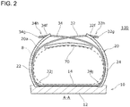
Fig. 2 is a cross-sectional view taken along line A-A of the shoe ofFig. 1 . -
Fig. 3 is an enlarged view illustrating a forming portion and a support member of the shoe ofFig. 1 in an enlarged manner. -
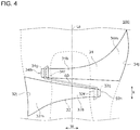
Fig. 4 is a plan view schematically illustrating the support member ofFig. 3 . -
Fig. 5 is an arrangement diagram illustrating an arrangement example according to a tightening force of the support member ofFig. 3 . -
Fig. 6 is an arrangement diagram illustrating an arrangement example according to a load from a foot of the support member ofFig. 3 . -
Fig. 7 is an arrangement diagram illustrating a first arrangement example according to an exercise of the support member ofFig. 3 . -
Fig. 8 is an arrangement diagram illustrating a second arrangement example according to the exercise of the support member ofFig. 3 . -
Fig. 9 is an arrangement diagram illustrating a third arrangement example according to the exercise of the support member ofFig. 3 . -
Fig. 10 is an arrangement diagram illustrating an arrangement example the support member ofFig. 3 corresponding to an arch of a foot. -
Fig. 11 is a shape diagram illustrating an example of a rigidity reduced portion of the support member ofFig. 3 . -
Fig. 12 is another shape diagram illustrating an example of the rigidity reduced portion of the support member ofFig. 3 . -
Fig. 13 is still another shape diagram illustrating an example of the rigidity reduced portion of the support member ofFig. 3 . -
Fig. 14 is an enlarged view illustrating the periphery of a string passing structure of the support member ofFig. 3 in an enlarged manner. -
Fig. 15 is an enlarged view illustrating the periphery of a string passing structure of the forming portion of the shoe ofFig. 1 in an enlarged manner. -
Fig. 16 is a graph illustrating a result of a tensile test of the support member ofFig. 3 . -
Fig. 17 is a schematic diagram schematically illustrating a force acting on each portion of the shoe ofFig. 1 . -
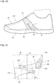
Fig. 18 is a plan view schematically illustrating a shoe according to a first variation. -
Fig. 19 is a cross-sectional view taken along line B-B of the shoe ofFig. 18 . -
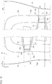
Fig. 20 is a development view in which a shoe tongue of the shoe ofFig. 18 is developed on a plane. -
Fig. 21 is a plan view schematically illustrating a shoe according to a second variation. -
Fig. 22 is a cross-sectional view taken along line M-M of the shoe ofFig. 21 . -
Fig. 23 is a cross-sectional view taken along line N-N of the shoe ofFig. 21 . -
Fig. 24 is a plan view schematically illustrating a shoe according to a third variation. -
Fig. 25 is a cross-sectional view taken along line P-P of the shoe ofFig. 24 . - A shoe desirably has a characteristic to fit well to a shape of a foot with an excellent touch on the foot (hereinafter referred to as "fit feeling") during normal time such as during rest or while walking, and a characteristic to restrain the foot so as not to move with respect to an outsole (hereinafter referred to as "holding property") during exercise. When the holding property is increased, an amount of wobble of an upper during motion becomes small, and a characteristic that the upper receives a force applied in a direction in which the foot slips out of the outsole of the shoe (hereinafter referred to as "stability") is increased. However, the smaller the gap between the foot and the upper, the better the holding property and the higher the stability, but the lower the fit feeling, so that it is difficult to satisfy both.
- Herein, a shoe disclosed in
Patent Document 1 is considered from this viewpoint. This shoe includes a pair of auxiliary tightening members extending from a base end side to a free end. A shoelace is allowed to pass through a ring connected to the free end, and when the shoelace is tightened, the auxiliary tightening members are tightened together with an upper lace stay. A base end of one of the auxiliary tightening members is firmly joined to a portion slightl anterior to an arch of the foot of a bottom edge on an inner side, and a base end of the other of the auxiliary tightening members is firmly joined to a portion of a bottom edge on an outer side slightl posterior to the base end of one of the auxiliary tightening members. - In this shoe, the free end of the auxiliary tightening member is not fixed to the upper lace stay. Therefore, when the free end is firmly tightened with the shoelace, the upper lace stay on the side opposite to the auxiliary tightening member is firmly tightened together, so that the foot is firmly tightened from both the inner side and the outer side. Therefore, when the free end is firmly tightened in a static state in order to enhance the holding property, the upper lace stay is also firmly tightened at the same time, so that the fit feeling is lowered. Also, when the free end is loosely tightened in order to improve the fit feeling, the upper lace stay is also loosely tightened at the same time, so that the holding property is lowered. That is, it may be said that, in this shoe, it is difficult to satisfy both the fit feeling and holding property because a force of tightening the foot hardly changes when a person exercises from the force when the person rests.
- The present invention is achieved based on the above-described considerations, and an object thereof is to change the force of tightening the foot during exercise from that during rest by fixing a tip end of a support member to the upper, thereby satisfying both the fit feeling during rest and the holding property during exercise.
- The present invention is hereinafter described based on preferred embodiments with reference to the drawings. In the embodiment and variation, the same or equivalent components and members are assigned with the same reference numerals, and description is not repeated appropriately. Also, a dimension of the member in each drawing is appropriately scaled in order to facilitate understanding. Also, some members not important for describing the embodiment in each drawing are omitted.
- In addition, terms including ordinal numbers such as first and second are used for describing various components, but the terms are used only for the purpose of distinguishing one component from other components; the components are not limited by the terms.
- Hereinafter, a configuration of a
shoe 100 according to an embodiment of the present invention is described with reference to the drawings.Fig. 1 is a plan view schematically illustrating theshoe 100 according to the embodiment. In the following drawings includingFig. 1 , a shoe for a right foot is illustrated unless otherwise described, but the description of this specification is similarly applied to a shoe for a left foot. - The
shoe 100 of this embodiment may be used as a shoe for walking or running, or a sporting shoe for tennis, basketball and the like, for example. Theshoe 100 includes a sole 10 and an upper 20. As illustrated inFig. 1 , a medial side (left side in the drawing) from a width direction center line La of the upper 20 is referred to as amedial side portion 22, and a lateral side (right side in the drawing) from the width direction center line La is referred to as alateral portion 24. A direction from the lateral side toward the medial side is referred to as inward, and the opposite direction is referred to as outward. A direction along the center line La is referred to as a "longitudinal direction". In each drawing, arrow W indicates the width direction, and arrow X indicates the longitudinal direction. In addition, a direction toward a toe side along the center line La is referred to as "forward" or "front", and the opposite side is referred to as "rearward" or "rear". Therefore, the width direction is orthogonal to the center line La. -
Fig. 2 is a longitudinal sectional view taken along line A-A inFig. 1 . An upper side in a state in which theshoe 100 is placed on a horizontal plane (hereinafter referred to as" horizontal state") is referred to as "upward" or "upper", and the opposite side is referred to as "downward" and "lower". Also, in the horizontal state, a direction extending vertically is referred to as "vertical direction". - The upper 20 includes the
medial foot portion 22, thelateral foot portion 24, a first formingportion 26, a second formingportion 28, afirst support member 32, asecond support member 34, ashoelace 60, and ashoe tongue 70. The upper 20 surrounds aninner space 20a for accommodating the foot. Acentral opening 20c is formed forward from afoot insertion portion 20b on the upper 20. The first formingportion 26 and the second formingportion 28 are sometimes collectively referred to as the forming portion. Also, when thefirst support member 32 and thesecond support member 34 are sometimes collectively referred to as the support member. - The sole 10 includes an
outsole 12 and aninsole 14. The sole 10 is fixed to the upper 20 by means such as adhesion. - The forming portion is described with reference to
Fig. 3 , too.Fig. 3 is an enlarged view illustrating the forming portion and the support member in an enlarged manner. The first formingportion 26 is provided on the medial side of thecentral opening 20c. The second formingportion 28 is provided on the lateral side of thecentral opening 20c. That is, the first formingportion 26 and the second formingportion 28 are arranged across thecentral opening 20c in the width direction. A plurality ofstring passing portions 62 is formed on each of the first formingportion 26 and the second formingportion 28. Thestring passing portion 62 is a portion through which theshoelace 60 is allowed to pass; this may be a through-hole, a string hanging portion or the like. As an example, thestring passing portion 62 of this embodiment is a through-hole penetrating vertically. In each of the first formingportion 26 and the second formingportion 28, sixstring passing portions 62 are arranged at predetermined intervals in a substantially longitudinal direction. - If the
string passing portion 62 has low rigidity, a tension of theshoelace 60 is escaped during high-strength exercise, and a support function of the support member cannot be fully exhibited. Therefore, in this embodiment, the first and second formingportions structures string passing portion 62, respectively. The reinforcingstructures portions - In addition, the
string passing portion 62 out of the first and second formingportions shoelace 60 is allowed to pass of thestring passing portion 62 may be configured to have higher rigidity than the surroundings. For example, a reinforcing member such as a metal or resin eyelet or hook may be provided on the edge of the hole of thestring passing portion 62, or the edge of the hole of thestring passing portion 62 may be made thicker than the surroundings by holing or the like. Also, out of the first and second formingportions areas 26g and 28g of a fixing portion of the support member to be described later may have higher rigidity than the surroundings . Note that the surroundingareas 26g and 28g are areas where through-holes - The support member is described with reference to
Fig. 4 , too.Fig. 4 is a plan view schematically illustrating the support member. The first andsecond support members outsole 12, theinsole 14, or a lower portion of the upper 20, or may be fixed therebetween. In the example ofFig. 2 , the base ends 32j and 34j are fixed between the upper 20 and theinsole 14. - When flexibility of the support member is too low, feeling when the support member abuts the foot is deteriorated. Therefore, the support member of this embodiment is formed of a material having higher flexibility than that of a material of the upper 20. In other words, the support member is formed of a material more flexible than the material of the upper 20.
- As illustrated in
Fig. 2 , the first andsecond support members Fig. 3 , thetip end 32h of thefirst support member 32 passes through the through-hole 28h provided on the second formingportion 28 from below upward to protrude on an upper surface of the second formingportion 28. Thetip end 32h includes a fixedportion 32f fixed to a lower side or an upper side of the second formingportion 28. Thetip end 34h of thesecond support member 34 passes through the through-hole 26h provided on the first formingportion 26 from below upward to protrude on an upper surface of the first formingportion 26. Thetip end 34h includes a fixedportion 34f fixed to a lower side or an upper side of the first formingportion 26. The through-holes portions - As illustrated in
Fig. 4 , first and secondstring passing structures second support members string passing structures shoelace 60 to pass therethrough. Thestring passing structures second support members - The fixed
portions string passing structures string passing structures string passing structures Fig. 4 , the fixedportions string passing structures portions string passing structures holes portions string passing structures - A shape of the support member is described. As the shape of the
support members support members - In the example of
Fig. 4 , thesupport members portions width changing portions width changing portions portions width changing portions portions Fig. 4 , the longitudinal direction width of the belt-shapedportion 34b is substantially constant, and the longitudinal direction width of the belt-shapedportion 32b gradually decreases toward the tip end side. - The
shoelace 60 is described. Theshoelace 60 passes through the plurality ofstring passing portions 62 and thestring passing structures Fig. 3 , theshoelace 60 passes through thestring passing portion 62 and continuously passes through thestring passing structures shoelace 60 does not pass through thestring passing portion 62 between thestring passing structures string passing structures shoelace 60 passes continuously, a string tightening force is evenly applied to thestring passing structures - The
shoe tongue 70 is described. As illustrated inFigs. 1 and2 , theshoe tongue 70 is provided on theinner space 20a side of the upper 20. Theshoe tongue 70 covers thecentral opening 20c inside the upper 20. The support member extends in the width direction on an upper surface side of theshoe tongue 70. A part of the support member is interposed between theshoe tongue 70 and the upper 20. Theshoelace 60 is arranged on an upper surface of theshoe tongue 70. - Next, an arrangement example of the support member is described. The support member is a member which receives tightening of the
shoelace 60. Therefore, the support member may also be arranged in consideration of a string tightening direction of theshoelace 60.Fig. 5 is an arrangement diagram illustrating an arrangement example of the support member according to the tightening force. In the example ofFig. 5 , tension indicated by arrows d1 and d2 (hereinafter referred to as forces d1 and d2) is applied to thesecond support member 34 in a tightening direction of theshoelace 60. A slightly forward force d1 in the width direction is applied to a front end of thestring passing structure 34g by the tension of theshoelace 60. A slightly rearward force d2 in the width direction is applied to a rear end of thestring passing structure 34g by the tension of theshoelace 60. - By receiving the forces d1 and d2, a tightening force indicated by arrow D (hereinafter referred to as a tightening force D) acts on the
second support member 34 as a resultant force. The tightening force D is a force in a direction from the medial side toward the lateral side. Thesecond support member 34 extends in a direction of the tightening force D corresponding to the tightening force D. Thefirst support member 32 similarly extends in the direction of the tightening force of theshoelace 60. - The support member is a member which receives a load from the foot during exercise. Therefore, the support member may also be arranged in consideration of the direction in which the load from the foot is applied during exercise.
Fig. 6 is an arrangement diagram illustrating an arrangement example of the support member according to the load from the foot. In the example ofFig. 6 , a load indicated by arrow E (hereinafter referred to as a load E) acts on thesecond support member 34 in the direction of the load from the foot. In order to correspond to the load E, thesecond support member 34 extends in the direction in which the load E from the foot is applied. Thefirst support member 32 similarly extends in the direction in which the load from the foot is applied. - Since the direction in which the load from the foot is applied during exercise differs depending on the content of the exercise, the support member may also be arranged according to the load direction of each target exercise.
Figs. 7 to 9 are arrangement diagrams illustrating an arrangement example of the support member according to the exercise. As illustrated inFigs. 7 to 9 , the support member may also be arranged in a position or in a direction based on the load direction of each target exercise. - In the example of
Fig. 7 , thefirst support member 32 on the medial side is arranged anterior to thesecond support member 34 on the lateral side to support a bone raised portion in the vicinity of the thenar, and thesecond support member 34 on the lateral side supports a bone raised portion in a portion posterior to the hypothenar. As a result, an effect of suppressing excessive fall of the foot at the time of motion of drastically falling down on the medial side is obtained. - In the example of
Fig. 8 , thefirst support member 32 on the medial side is arranged posterior to thesecond support member 34 on the lateral side to support the vicinity of the longitudinal center of the arch of the foot, and thesecond support member 34 on the lateral side supports a bone raised portion in the vicinity of the hypothenar. As a result, it is possible to obtain an effect of suppressing depression of the arch of the foot, and an effect of suppressing displacement between the shoe and the foot in a lateral direction at the time of motion in which a large load is applied to a front lateral side. - In the example of
Fig. 9 , thefirst support member 32 on the medial side supports the vicinity of the longitudinal center of the arch of the foot, and thesecond support member 34 on the lateral side supports is arranged posterior to thefirst support member 32 on the medial side to support a bone raised portion in a central area between the hypothenar and the heel. As a result, it is possible to obtain an effect of suppressing depression of the arch of the foot, and an effect of suppressing displacement between the shoe and the foot in a lateral direction at the time of motion in which a large load is applied to a middle lateral side. - The
first support member 32 on the medial side may also be arranged in a position where the fall of the arch may be suppressed during exercise.Fig. 10 is an arrangement diagram illustrating an arrangement example of the support member to correspond to the fall of an arch 8a. In the example ofFig. 10 , in order to suppress the fall of the arch 8a, thefirst support member 32 on the medial side is arranged so as to be in contact with the arch 8a. The support member comes into contact with the arch 8a, thereby applying a support force indicated by arrow F (hereinafter referred to as a support force F) to the arch 8a based on the tension of the shoelace. By applying the support force F, the support member may raise the arch 8a and suppress the fall of the arch 8a. - The shape of the support member is further described. When the support member is pressed strongly against the bone raised portion such as a bone end or a bone head for a long time, a pressed portion might become painful. Therefore, in the case where the support member supports the bone raised portion such as the bone end and the bone head, rigidity of the area pressed by these portions may be made low. For example, the
second support member 34 on the lateral side which supports the bone raised portion in the vicinity of the hypothenar may be configured to have lower rigidity than that of thefirst support member 32 on the medial side. In this case, as an example, thesecond support member 34 on the lateral side may be formed of a material having lower rigidity than a material of thefirst support member 32 on the medial side. Also, lower areas of the first andsecond support members - From a similar viewpoint, a rigidity reduced
portion 36 having lower rigidity than the surroundings may be provided in a longitudinal direction intermediate area of thesecond support member 34 on the lateral side. The rigidity reducedportion 36 is provided in a portion which comes into contact with the bone raised portion such as the bone end and the bone head out of the support member. By including the rigidity reducedportion 36, it is possible to reduce the pressure from the support member to the bone raised portion such as the bone end and the bone head.Figs. 11 to 13 are shape diagrams illustrating an example of the rigidity reducedportion 36 of the support member. In the example ofFig. 11 , the rigidity reducedportion 36 of thesecond support member 34 includes aflexible portion 36s formed of a material more flexible than the surroundings. In the example ofFig. 12 , the rigidity reducedportion 36 of thesecond support member 34 includes a plurality of slit-shapedcutouts 36p. In the example ofFig. 13 , the rigidity reducedportion 36 of thesecond support member 34 includes asingle cutout 36q. - The
string passing structures Fig. 14 is an enlarged view illustrating the periphery of thestring passing structures string passing structures string passing structures support members deformation suppressing structures string passing structures - As the
deformation suppressing structures string passing structures string passing structures string passing structures - From the viewpoint of reducing the deformation of the
string passing structures string passing structures Fig. 14 , the width direction stretching property of thestring passing structures portions string passing structures portions -
Fig. 15 is an enlarged view illustrating the periphery of thestring passing structures portions string passing structures area 30d in which the first and secondstring passing structures portions low stretching portion 30e having lower width direction stretching property than the surroundings may be provided. - As an example, the fixing
area 30d may be a portion between a front end of the tip ends 32h and 34h of a front support member (second support member 34 in the example ofFig. 15 ) out of the first and second formingportions first support member 32 in the example ofFig. 15 ) out of the first andsecond support members entire fixing area 30d may be thelow stretching portion 30e, or a part of the fixingarea 30d may be thelow stretching portion 30e. - The
low stretching portion 30e may also be provided continuously on the upper 20 from the viewpoint of exerting a drag opposable to a tension in the fixing portion of the tip ends 32h and 34h when the tension toward the base ends 32j and 34j is applied to the fixing portion of the tip ends 32h and 34h. As an example, as illustrated inFig. 15 , thelow stretching portion 30e may also be provided continuously from the fixing portion of the tip ends 32h and 34h in the first and second formingportions medial portion 22 and thelateral portion 24. - As indicated by a broken line in
Fig. 15 , thelow stretching portion 30e on themedial portion 22 side is provided in a belt-shaped area extending from the first formingportion 26 to the base end (portion fixed to the sole 10) on the lower side of themedial portion 22 across themedial portion 22 in a longitudinal width of thetip end 34h of thesecond support member 34. Also, thelow stretching portion 30e on thelateral portion 24 side is provided in a belt-shaped area extending from the second formingportion 28 to the base end (portion fixed to the sole 10) on the lower side of thelateral portion 24 across thelateral portion 24 in a longitudinal width of thetip end 32h of thefirst support member 32. That is, thelower end 30f of thelow stretching portion 30e extends to a portion fixed to the sole 10 of themedial portion 22 and thelateral portion 24. - In this case, when the tension toward the base ends 32j and 34j of the first and
second support members low stretching portion 30e extending to the upper 20 may apply the drag opposable to the tension to the fixing portions of the tip ends 32h and 34h. - For example, the
low stretching portion 30e may be formed of a low stretching material having a lower stretching property than the surroundings of thelow stretching portion 30e, a material thicker than the surroundings, a material having a higher density than the surroundings, or a material harder than the surroundings. - In particular, the
low stretching portion 30e having a lower width direction stretching property than the surroundings may be provided in acorresponding area 30c corresponding to the longitudinal center of the first and secondstring passing structures portions portions area 30c (area in the vicinity of the center line Lc inFig. 15 ) may be thelow stretching portion 30e. Note that, out of the first and second formingportions portions low stretching portion 30e. - Next, the rigidity of the support member is described.
Fig. 16 is a graph illustrating a result of a tensile test of a sample T of the support member. In this graph, an elongation amount is plotted as a percentage of a maximum elongation amount along the abscissa, and a load is plotted along the ordinate. This graph illustrates the test result of the load in a direction applied from the foot regarding the sample T of the support member formed of a predetermined material into a predetermined shape. When the load (= rigidity) with respect to the elongation amount is too high, the fit feeling is impaired, and when the load (= rigidity) with respect to the elongation amount is too low, the stability is impaired. - From the viewpoint of securing the fit feeling and stability, the present inventors studied the rigidity when the elongation amount is near zero (initial rigidity) and the rigidity when the elongation amount is 100%. As a result of this study, it was suggested that the fit feeling and stability may be secured in a range of the initial rigidity not lower than 0.01 N/mm and not higher than 0.15 N/mm and in a range of the rigidity when the elongation amount is 100% not lower than 0.5 N/mm and not higher than 10 N/mm. The sample is not limited to the above, and is selected according to a desired balance between the fit feeling and stability.
- With reference to
Fig. 17 , an example of a holding motion during exercise of theshoe 100 configured as described above is described.Fig. 17 is a schematic diagram schematically illustrating a force acting on each portion of theshoe 100 when the load is applied. Arrows G to J in this drawing indicate the forces acting on each portion when theshoe 100 receives an outward load from the foot. - (1) When the load is applied to the
shoe 100, as indicated by arrow G, the outward load from the foot (hereinafter referred to as a load G) is applied to thesupport member 34 on the lateral side. - (2) When the load G is applied to the
support member 34, as indicated by arrow H, an outward tension (hereinafter referred to as a tension H) acts on theshoelace 60 via thestring passing structure 34g. - (3) When the tension H acts on the
shoelace 60, as indicated by arrow I, an inward force (hereinafter referred to as a force I) acts on thestring passing structure 32g of thesupport member 32 on the medial side via theshoelace 60. - (4) When the force I acts on the
string passing structure 32g, as indicated by arrow J, an outward force (hereinafter referred to as a force J) acts on anentire support member 32. As a result, the medial side of a foot is supported by thesupport member 32, the lateral side of the foot is supported by thesupport member 34, so that the entire foot is firmly held and wobble of the foot may be reduced. - When the
shoe 100 receives an inward load from the foot also, by a similar functional mechanism, the medial side of a foot is supported by thesupport member 32, the lateral side of the foot is supported by thesupport member 34, so that the entire foot is firmly held and the wobble of the foot may be reduced. That is, even when the foot is not completely restrained during rest, the stability may be ensured by a dynamic force input and transmission during exercise. Also, if the foot is not restrained completely during rest, a degree of freedom of the foot may be ensured during rest and while walking, so that a comfortable fit feeling may be obtained. Also, by appropriately selecting the rigidity of the support member according to an intended use of the shoe, balance between the degree of freedom of the foot during rest and the stability during exercise may be adjusted. - An outline of one aspect of the present invention is described. A
shoe 100 according to an aspect of the present invention is provided with a first formingportion 26 provided on a medial side and a second formingportion 28 provided on a lateral side across acentral opening 20c formed forward from afoot insertion portion 20b of an upper 20 on each of which astring passing portion 62 is formed, a first support member 32 atip end 32h of which is fixed to the second formingportion 28, including a firststring passing structure 32g provided at thetip end 32h, and extending downward so as to abut a medial side of a foot inside the upper 20, a second support member 34 atip end 34h of which is fixed to the first formingportion 26, including a secondstring passing structure 34g provided at thetip end 34h, and extending downward so as to abut a lateral side of the foot inside the upper 20, and ashoelace 60 which passes through thestring passing portion 62 and continuously passes through the first and secondstring passing structures - According to this aspect, the tip end of the support member is fixed to the upper 20, so that the force of tightening the foot during exercise may be changed from that during stay, thereby improving both the fit feeling during rest and the holding property during exercise.
- The first and second forming
portions structures string passing portion 62. In this case, since thestring passing portion 62 is reinforced by the reinforcingstructures - As described above, reinforcing
structures shoelace 60 is allowed to pass of thestring passing portion 62 higher than the surroundings, for example, a reinforcing member such as a metal or resin eyelet or hook may be provided on the edge of the hole of thestring passing portion 62, or the edge of the hole of thestring passing portion 62 may be made thicker than the surroundings by holing or the like. A plurality of these reinforcing structures may also be provided in combination. - The first and
second support members deformation suppressing structures string passing structures string passing structures - The first and
second support members portions - The
low stretching portion 30e having a lower width direction stretching property than the surroundings may be provided in the correspondingarea 30c corresponding to the longitudinal center of the first and secondstring passing structures portions area 30c is suppressed, the escape of the tension decreases and the holding property is improved. - The
low stretching portion 30e having a lower width direction stretching property than the surroundings may be provided in the fixingarea 30d in which the first and secondstring passing structures portions area 30d is suppressed, the escape of the tension decreases and the holding property is improved. - The rigidity reduced
portion 36 having lower rigidity than the surroundings may be provided in a longitudinal direction intermediate area of at least one of the first orsecond support member - The rigidity reduced
portion 36 may also include theflexible portion 36s more flexible than the surroundings or thecutout 36p. In this case, the support member may have the flexibility and strength. - The first and
second support members width changing portions - The lower areas of the first and
second support members - The first and
second support members - The example of the embodiment of the present invention is heretofore described in detail. The above-described embodiment is merely a specific example for carrying out the present invention. The contents of the embodiment do not limit the technical scope of the present invention, and many design changes such as changes, additions, deletions and the like of the components may be made without departing from the spirit of the invention defined in claims. In the above-described embodiment, the contents that can be changed in the design are described with the notation such as "of the embodiment", "in the embodiment, but the design change is also allowed to the contents without such notation. Moreover, hatching given to the cross-section of the drawing does not limit the material of the hatched object.
- Hereinafter, variations are described. In the drawings and descriptions of the variations, the same reference numerals are assigned to the same or equivalent components and members as those of the embodiment. The description overlapping with that of the embodiment is omitted as appropriate, and the configuration different from that of the embodiment is mainly described.
- A configuration of a
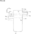
shoe 200 according to a first variation is described.Fig. 18 is a plan view schematically illustrating theshoe 200 according to the first variation corresponding toFig. 1 . In this drawing, ashoelace 60 is not illustrated for easier understanding.Fig. 19 is a cross-sectional view taken along line B-B of theshoe 200 corresponding toFig. 2 .Fig. 20 is a development view in which ashoe tongue 70 of theshoe 200 is developed on a plane. Theshoe 200 according to the first variation is different from theshoe 100 according to the embodiment in a configuration of theshoe tongue 70; the other configurations are similar. Therefore, the configuration of theshoe tongue 70 is mainly described. - The
shoe tongue 70 covers thecentral opening 20c inside the upper 20. Theshoe tongue 70 is different from that in the embodiment in including aprotrusion 70e protruding in a width direction. Theprotrusion 70e extends downward on an inner side (side opposite to the upper 20) of first andsecond support members support members protrusion 70e and the upper 20. Since theprotrusion 70e is interposed between a support member and a foot, it is possible to prevent thesupport members - The
protrusion 70e may include alower end 70j extending below base ends 32j and 34j of thesupport members support members lower end 70j of theprotrusion 70e. In this case, an area in which thesupport members - The
lower end 70j of theprotrusion 70e may be an unfixed free end, fixed to anoutsole 12, aninsole 14, or a lower portion of the upper 20, or may be fixed therebetween. Thelower end 70j of this variation is fixed between the upper 20 and theinsole 14 from the viewpoint of suppressing forward movement of theshoe tongue 70 and thesupport members shoe 200. The base ends 32j and 34j of thesupport members protrusion 70e. In this case, displacement in positional relationship among thesupport members protrusion 70e, and the upper 20 may be made small. - As indicated by a solid line in
Fig. 20 , theprotrusion 70e may have a shape overlapping with a part of the first andsecond support members Fig. 20 , this may have a shape overlapping with an entire first andsecond support members protrusion 70e has a shape including a part or all of the first andsecond support members - As illustrated in
Fig. 18 , a position regulator 72 for regulating positions of the first andsecond support members shoe tongue 70 of this variation. By including the position regulator 72, it is possible to suppress the support member from moving in a longitudinal direction, and to make the displacement in the positional relationship between thesupport members - A configuration of the position regulator 72 is not limited, but the position regulator 72 of this variation is a belt-shaped member extending in the longitudinal direction and is fixed to the
shoe tongue 70 by means of sewing and the like at a plurality of positions separated in the longitudinal direction. The position regulator 72 is provided at the width direction center of theshoe tongue 70 and forms agap 72s for the support member to pass in the width direction between the same and the upper surface of theshoe tongue 70. By allowing the support member to pass through thegap 72s, the position of the support member in the longitudinal direction is regulated to a longitudinal range of thegap 72s. The position regulator 72 is not necessarily provided at the width direction center of theshoe tongue 70, and the position regulator 72 may also be arranged in a position near a medial side or a lateral side from the width direction center. - The first and
second support members gap 72s, but in this variation, they are allowed to pass throughdifferent gaps 72s. In this case, the positions of thefirst support member 32 and thesecond support member 34 may be arranged in more appropriate positions. Also, both the first andsecond support members single gap 72s, or only one of the support members may be allowed to pass therethrough. Thegap 72s may or may not allow theshoelace 60 to passes therethrough. - A configuration of a
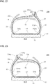
shoe 300 according to a second variation is described.Fig. 21 is a plan view schematically illustrating theshoe 300 according to the second variation corresponding toFig. 1 .Fig. 22 is a cross-sectional view taken along line M-M of theshoe 300.Fig. 23 is a cross-sectional view taken along line N-N of theshoe 300. Theshoe 300 according to the second variation is different from theshoe 100 according to the embodiment in configurations of first andsecond support members second support members - The
first support member 332 of this variation differs from afirst support member 32 of the embodiment in not including atip end 32h but including a foldedportion 332p and a lateral sidebase end 332n; and the other configurations are similar. Thefirst support member 332 is a member extending from a medial sidebase end 332j on a lower side of a medial side of a foot to a lateral sidebase end 332n on a lower side of a lateral side of a foot, and a foldedportion 332p is formed in the middle. The foldedportion 332p passes through a through-hole 28h provided on a second formingportion 28 from below upward to protrude on an upper surface of the second formingportion 28. The foldedportion 332p is provided with a firststring passing structure 332g. - The medial side
base end 332j corresponds to thebase end 32j and is fixed between an upper 20 and aninsole 14 on a medial side in the example ofFig. 22 . The lateral sidebase end 332n is fixed between the upper 20 and theinsole 14 on a lateral side in the example ofFig. 22 . The lateral sidebase end 332n may be fixed to theoutsole 12, theinsole 14, or a lower portion of the upper 20, or may be fixed therebetween. - Note that the
first support member 32 of the embodiment and thefirst support member 332 of this variation have one end (base end 32j, medial sidebase end 332j) fixed between the upper 20 and theinsole 14 and the like on the medial side, and the other end (tip end 32h, lateral sidebase end 332n) fixed between the second formingportion 28 or the upper 20 and theinsole 14 and the like on the lateral side. That is, it may be said that these are common technical ideas in a point that both ends of the support member are fixed to somewhere. - As illustrated in
Fig. 21 , in the vicinity of the lateral sidebase end 332n of thefirst support member 332, a longitudinalwidth changing portion 332m a longitudinal width of which gradually increases downward is provided. - The folded
portion 332p may be fixed to the second formingportion 28, but is not fixed in this example. Therefore, by tightening ashoelace 60, a position of the foldedportion 332p in thefirst support member 332 changes. - The
second support member 334 of this variation differs from thesecond support member 34 of the embodiment in not including atip end 34h but including a foldedportion 334p and a medial sidebase end 334n; and the other configurations are similar. Thesecond support member 334 is a member extending from a lateral sidebase end 334j on the lower side of the lateral to a medial sidebase end 334n on the lower side of the medial side of a foot, and a foldedportion 334p is formed in the middle. The foldedportion 334p passes through a through-hole 26h provided on the first formingportion 26 from below upward to protrude on an upper surface of the first formingportion 26. The foldedportion 334p is provided with a secondstring passing structure 334g. - The lateral side
base end 334j corresponds to thebase end 34j and is fixed between the upper 20 and theinsole 14 on the medial side in the example ofFig. 23 . The medial sidebase end 334n is fixed between the upper 20 and theinsole 14 on the lateral side in the example ofFig. 23 . The medial sidebase end 334n may be fixed to theoutsole 12, theinsole 14, or the lower portion of the upper 20, or may be fixed therebetween. - Note that the
second support member 34 of the embodiment and thesecond support member 334 of this variation have one end (base end 34j , lateral sidebase end 334j) fixed between the upper 20 and theinsole 14 and the like on the lateral side, and the other end (tip end 34h, medial sidebase end 334n) fixed between the first formingportion 26 or the upper 20 and theinsole 14 and the like on the medial side. That is, it may be said that these are common technical ideas in a point that both ends of the support member are fixed to somewhere. - As illustrated in
Fig. 21 , in the vicinity of the medial sidebase end 334n of thesecond support member 334, a longitudinalwidth changing portion 334m a longitudinal width of which gradually increases downward is provided. - The folded
portion 334p may be fixed to the first formingportion 26, but is not fixed in this example. Therefore, by tightening theshoelace 60, a position of the foldedportion 334p in thesecond support member 334 changes. - The second variation has functions and effects similar to those of the above-described embodiment. In addition, since the
first support member 332 and thesecond support member 334 arranged in positions separated in the longitudinal direction support the medial side of the foot and the lateral side of a foot, respectively, more appropriate support force may be applied along a shape of the foot. - A configuration of a
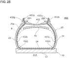
shoe 400 according to a third variation is described.Fig. 24 is a plan view schematically illustrating theshoe 400 according to the third variation corresponding toFig. 1 .Fig. 25 is a cross-sectional view taken along line P-P of theshoe 400. Theshoe 400 according to the third variation is different from ashoe 100 according to the embodiment in a configuration of a bothside support member 432, and the other configurations are similar. That is, theshoe 400 includes the bothside support member 432 in place of first and second support members. Therefore, the configuration of the bothside support member 432 is mainly described. - The both
side support member 432 of this variation differs from afirst support member 32 of the embodiment in not including atip end 32h but including first and second foldedportions base end 432j, and a lateral sidebase end 432n; and the other configurations are similar. The bothside support member 432 is a member extending from the medial sidebase end 432j on a lower side of a medial side of the foot to the lateral sidebase end 432n on a lower side of a lateral side of a foot, and the first and second foldedportions portion 432p is provided on the side opposite to the lateral sidebase end 432n of the second foldedportion 432q, and the second foldedportion 432q is provided on the side opposite to the medial sidebase end 432j of the first foldedportion 432p. - The first folded
portion 432p passes through a through-hole 26h provided on a first formingportion 26 from below upward to protrude on an upper surface of the first formingportion 26. The first foldedportion 432p is provided with a firststring passing structure 432g. The second foldedportion 432q passes through a through-hole 28h provided on a second formingportion 28 from below upward to protrude on an upper surface of the second formingportion 28. The second foldedportion 432q is provided with a secondstring passing structure 432k. - The medial side
base end 432j and the lateral sidebase end 432n may be fixed to anoutsole 12, aninsole 14, or a lower portion of an upper 20, or may be fixed therebetween. In the example ofFig. 25 , the medial sidebase end 432j is fixed between the upper 20 and theinsole 14 on a medial side, and the lateral sidebase end 432n is fixed between the upper 20 and theinsole 14 on a lateral side. - In the example of
Fig. 24 , the through-hole 26h and the through-hole 28h are arranged anterior to a foremost one out of a plurality ofstring passing portions 62 in the first and second formingportions portions string passing structures string passing portions 62. Ashoelace 60 passes through the first and secondstring passing structures - Note that the
first support member 32 of the embodiment and the bothside support member 432 of this variation have one end (base end 32j, medial sidebase end 432j) fixed between the upper 20 and theinsole 14 and the like on the medial side, and the other end (tip end 32h, lateral sidebase end 432n) fixed between the second formingportion 28 or the upper 20 and theinsole 14 and the like on the lateral side. That is, it may be said that these are common technical ideas in a point that both ends of the support member are fixed to somewhere. - As illustrated in
Fig. 24 , in the vicinity of the medial sidebase end 432j and the vicinity of the lateral sidebase end 432n of the bothside support member 432, a longitudinalwidth changing portion 432s a longitudinal width of which gradually increases downward is provided. - The first and second folded
portions portions shoelace 60, positions of the first and second foldedportions side support member 432 change. - The third variation has functions and effects similar to those of the above-described embodiment. In addition, since the both
side support member 432 supports the medial side of the foot and the lateral side of a foot as a substitution of the first and second support members, more appropriate support force may be applied along a shape of the foot. - In the description of the embodiment, the example in which the support member is provided inside the upper 20 is described, but the support member may also be provided outside the upper 20. In this case, the support member abuts the medial side of a foot and the lateral side of a foot indirectly.
- In the description of the embodiment, the example in which the
string passing portion 62 is the through-hole is described, but the present invention is not limited to this, and the string passing portion may adopt various structures. For example, the string passing portion may be a metal or resin eyelet, or a metal or resin hook. - In the description of the embodiment, the example in which the
string passing structures - In the description of the embodiment, the example in which the support member is integrally formed from the base ends 32j and 34j to the tip ends 32h and 34h is described, but the present invention is not limited to this, and the support member may be formed by connecting a plurality of separately formed members. The inner portion and the outer portion of the forming
portions - In the description of the embodiment, the example in which the rigidity reduced
portion 36 is provided in thesecond support member 34 is described, but the rigidity reducedportion 36 may also be provided in thefirst support member 32, or both the first andsecond support members portions 36 of the first andsecond support members - Each of the above-described variations has functions and effects similar to those of the above-described embodiment.
- Any combination of the above-described embodiments and variations is also useful as the embodiment of the present invention. A new embodiment generated by the combination has effects of each of the combined embodiments and variations.
- The present invention relates to a shoe and may be used for the shoe.
- 10 sole, 20 upper, 20a inner space, 20c central opening, 20d foot insertion portion, 22 medial portion, 24 lateral portion, 26 first forming portion, 26s reinforcing structure, 28 second forming portion, 30e low-stretching portion, 32 first support member, 32f fixed portion, 32g string passing structure, 32h tip end, 32j base end, 32k deformation suppressing structure, 32m longitudinal width changing portion, 34 second support member, 34f fixed portion, 34g string passing structure, 34h tip end, 34m longitudinal width changing portion, 36 rigidity reduced portion, 60 shoelace, 62 string passing portion, 70 shoe tongue, 70e protrusion, 70j lower end, 72 position regulator, 100, 200 Shoe.
Claims (14)
- A shoe comprising:a first forming portion provided on a medial side and a second forming portion provided on a lateral side across a central opening formed forward from a foot insertion portion of an upper on each of which a string passing portion is formed;a first support member a tip end of which is fixed to the second forming portion, including a first string passing structure provided at the tip end, and extending downward so as to abut a medial side of a foot;a second support member a tip end of which is fixed to the first forming portion, including a second string passing structure provided at the tip end, and extending downward so as to abut a lateral side of the foot; anda shoelace which passes through the string passing portion and continuously passes through the first and second string passing structures.
- The shoe according to claim 1, wherein the first and second forming portions include a reinforcing structure for reinforcing the string passing portion.
- The shoe according to claim 1 or 2, wherein the first and second support members include a deformation suppressing structure for reinforcing the first and second string passing structures.
- The shoe according to any one of claims 1 to 3, wherein the first and second support members include a belt-shaped portion.
- The shoe according to any one of claims 1 to 4, wherein a low stretching portion having a lower width direction stretching property than surroundings is provided in a corresponding area corresponding to a longitudinal center of the first and second string passing structures out of the first and second forming portions.
- The shoe according to any one of claims 1 to 5, wherein a low stretching portion having a lower width direction stretching property than surroundings is provided in a fixing area in which the first and second string passing structures are fixed out of the first and second forming portions.
- The shoe according to any one of claims 1 to 6, wherein a rigidity reduced portion having lower rigidity than surroundings is provided in a longitudinal direction intermediate area of at least one of the first or second support member.
- The shoe according to claim 7, wherein the rigidity reduced portion includes a cutout or a flexible portion more flexible than surroundings.
- The shoe according to any one of claims 1 to 8, wherein the first and second support members include a longitudinal width changing portion a longitudinal width of which gradually increases downward.
- The shoe according to any one of claims 1 to 9, wherein lower areas of the first and second support members have different stretching properties.
- The shoe according to any one of claims 1 to 10, wherein the first and second support members are formed of a material having flexibility higher than flexibility of a material of the upper.
- The shoe according to any one of claims 1 to 11, comprising: a shoe tongue which covers the central opening of the upper, wherein the shoe tongue includes a protrusion that protrudes in a width direction to extend downward inside the first and second support members.
- The shoe according to claim 12, wherein base ends of the first and second support members are arranged above a lower end of the protrusion.
- The shoe according to claim 12 or 13, wherein a position regulator for regulating positions of the first and second support members is provided on an upper surface of the shoe tongue.
Applications Claiming Priority (1)
| Application Number | Priority Date | Filing Date | Title |
|---|---|---|---|
| PCT/JP2019/014198 WO2020202322A1 (en) | 2019-03-29 | 2019-03-29 | Shoes |
Publications (3)
| Publication Number | Publication Date |
|---|---|
| EP3738459A4 EP3738459A4 (en) | 2020-11-18 |
| EP3738459A1 true EP3738459A1 (en) | 2020-11-18 |
| EP3738459B1 EP3738459B1 (en) | 2021-05-26 |
Family
ID=71131635
Family Applications (1)
| Application Number | Title | Priority Date | Filing Date |
|---|---|---|---|
| EP19817576.2A Active EP3738459B1 (en) | 2019-03-29 | 2019-03-29 | Shoes |
Country Status (6)
| Country | Link |
|---|---|
| US (2) | US11357289B2 (en) |
| EP (1) | EP3738459B1 (en) |
| JP (1) | JP6716795B1 (en) |
| CN (1) | CN112040806B (en) |
| BR (1) | BR112021000703B1 (en) |
| WO (1) | WO2020202322A1 (en) |
Cited By (1)
| Publication number | Priority date | Publication date | Assignee | Title |
|---|---|---|---|---|
| WO2021242810A1 (en) * | 2020-05-29 | 2021-12-02 | Nike Innovate C.V. | Upper including dynamic supports |
Families Citing this family (3)
| Publication number | Priority date | Publication date | Assignee | Title |
|---|---|---|---|---|
| USD1006427S1 (en) * | 2017-12-29 | 2023-12-05 | William I. CRAVEN | Removable shoe lace replacement overlay |
| US12274326B2 (en) | 2020-12-07 | 2025-04-15 | Asics Corporation | Shoe |
| US20250366561A1 (en) * | 2022-12-22 | 2025-12-04 | Sport Maska Inc. | Skate with foot wrapping system |
Family Cites Families (31)
| Publication number | Priority date | Publication date | Assignee | Title |
|---|---|---|---|---|
| US811316A (en) * | 1904-03-28 | 1906-01-30 | James A Mcpherson | Hockey-boot. |
| US1649173A (en) * | 1923-03-31 | 1927-11-15 | Mcdonough James | Orthopedic shoe |
| US2116445A (en) * | 1937-04-29 | 1938-05-03 | Vida L Moore | Article of footwear |
| US2182843A (en) * | 1938-06-04 | 1939-12-12 | Mortimer B Flynn | Shoe |
| US2539761A (en) * | 1948-07-03 | 1951-01-30 | Goodrich Co B F | Article of footwear |
| US3308829A (en) * | 1966-04-18 | 1967-03-14 | Clyde A Edwards | Corrective shoe with abduction strap |
| DE1685288B1 (en) * | 1967-04-08 | 1972-05-31 | Franz Fesl | Ski or Mountain boots with a tensionable support part for the foot arch |
| US4592154A (en) * | 1985-06-19 | 1986-06-03 | Oatman Donald S | Athletic shoe |
| US4811500A (en) * | 1987-02-06 | 1989-03-14 | L. A. Gear, Inc. | Article of footware having an adjustable instep supporting insert |
| FR2613599B1 (en) * | 1987-04-10 | 1990-11-30 | Salomon Sa | CLOSED FLAP SHOE, PARTICULARLY FOR SPORTS PRACTICE |
| US4926569A (en) * | 1988-10-31 | 1990-05-22 | Converse Inc. | Shoe with cradle arch support |
| FR2654592B1 (en) * | 1989-11-22 | 1992-02-28 | Salomon Sa | SPORTS SHOE HAVING AN INTERNAL TIGHTENING DEVICE OF THE KICKING AREA. |
| US5323549A (en) * | 1993-08-16 | 1994-06-28 | Sports Licensing, Inc. | Shoe equipped with internal orthotic cradle device |
| JPH0965908A (en) * | 1995-09-04 | 1997-03-11 | Daiwa Seiko Inc | shoes |
| IL123199A (en) * | 1998-02-05 | 2002-07-25 | Hadasit Med Res Service | Shoe with adjustable arch support |
| US6073370A (en) * | 1998-02-23 | 2000-06-13 | Shimano Inc. | Snowboard boot power lacing configuration |
| EP1190635B1 (en) * | 2000-04-28 | 2004-08-25 | Mizuno Corporation | Tight-binding structure for footwear |
| US6925734B1 (en) * | 2001-09-18 | 2005-08-09 | Reebok International Ltd. | Shoe with an arch support |
| AU2004231386C1 (en) * | 2003-04-24 | 2007-02-08 | Asics Corporation | Sports shoes having upper part with improved fitting property |
| US6952890B1 (en) * | 2003-09-02 | 2005-10-11 | Nike, Inc. | Lace retainer for footwear |
| JP4293557B2 (en) * | 2005-12-22 | 2009-07-08 | 株式会社ニューバランスジャパン | shoes |
| US8522455B2 (en) * | 2007-04-13 | 2013-09-03 | Nike, Inc. | Strap system with integrated eyelet |
| WO2011004422A1 (en) * | 2009-07-06 | 2011-01-13 | 株式会社アシックス | Shoe with shoelace fastener fitting structure |
| US8302329B2 (en) * | 2009-11-18 | 2012-11-06 | Nike, Inc. | Footwear with counter-supplementing strap |
| EP3056106B1 (en) * | 2013-10-09 | 2018-05-30 | ASICS Corporation | Exercise shoe |
| US9526300B2 (en) * | 2015-03-16 | 2016-12-27 | Anna Krengel | Dually adjustable, anchored, parallel lacing technology |
| US20170172248A1 (en) * | 2015-12-22 | 2017-06-22 | Mark Fadil | Arch Support |
| US10405607B2 (en) * | 2016-03-22 | 2019-09-10 | Nike, Inc. | Tensioning system for an article of footwear |
| US10039341B2 (en) * | 2016-07-18 | 2018-08-07 | Sport Maska Inc. | Skate boot and method of manufacture |
| US10660408B2 (en) * | 2018-04-06 | 2020-05-26 | Nike, Inc. | Article of footwear with closure system having a transverse flap with cables |
| US11013292B2 (en) * | 2018-09-28 | 2021-05-25 | Puma SE | Article of footwear having a sole structure |
-
2019
- 2019-03-29 WO PCT/JP2019/014198 patent/WO2020202322A1/en not_active Ceased
- 2019-03-29 BR BR112021000703-2A patent/BR112021000703B1/en active IP Right Grant
- 2019-03-29 US US16/609,438 patent/US11357289B2/en active Active
- 2019-03-29 JP JP2019551723A patent/JP6716795B1/en active Active
- 2019-03-29 EP EP19817576.2A patent/EP3738459B1/en active Active
- 2019-03-29 CN CN201980003702.6A patent/CN112040806B/en active Active
-
2022
- 2022-04-01 US US17/657,704 patent/US11779081B2/en active Active
Cited By (1)
| Publication number | Priority date | Publication date | Assignee | Title |
|---|---|---|---|---|
| WO2021242810A1 (en) * | 2020-05-29 | 2021-12-02 | Nike Innovate C.V. | Upper including dynamic supports |
Also Published As
| Publication number | Publication date |
|---|---|
| CN112040806A (en) | 2020-12-04 |
| WO2020202322A1 (en) | 2020-10-08 |
| US11779081B2 (en) | 2023-10-10 |
| US20220218071A1 (en) | 2022-07-14 |
| BR112021000703A2 (en) | 2021-04-13 |
| EP3738459A4 (en) | 2020-11-18 |
| JPWO2020202322A1 (en) | 2021-04-30 |
| US11357289B2 (en) | 2022-06-14 |
| JP6716795B1 (en) | 2020-07-01 |
| US20210244132A1 (en) | 2021-08-12 |
| BR112021000703B1 (en) | 2022-01-25 |
| CN112040806B (en) | 2022-07-05 |
| EP3738459B1 (en) | 2021-05-26 |
Similar Documents
| Publication | Publication Date | Title |
|---|---|---|
| US11779081B2 (en) | Shoe | |
| US8272148B2 (en) | Sports shoes having upper part with improved fitting property | |
| US8713821B2 (en) | Athletic shoes having an upper whose fitting property is improved | |
| EP0231118B1 (en) | Sports shoe | |
| CN105495845B (en) | Divergence type foot stabilizer system | |
| EP2826390B1 (en) | Lace-up fitting structure | |
| EP4159077A1 (en) | Shoe component and shoe | |
| AU2011275838B2 (en) | Shoe | |
| JP4293557B2 (en) | shoes | |
| EP4265143A1 (en) | Upper and shoe comprising same | |
| JP7159245B2 (en) | shoes | |
| US20220225736A1 (en) | Shoe | |
| CN119547960A (en) | Footwear | |
| JP2025131931A (en) | Upper and shoes equipped with same | |
| JP7656745B2 (en) | Shoes | |
| CN100411559C (en) | The sneakers which improved the comfort of the upper | |
| EP4029397A1 (en) | Shoe |
Legal Events
| Date | Code | Title | Description |
|---|---|---|---|
| STAA | Information on the status of an ep patent application or granted ep patent |
Free format text: STATUS: UNKNOWN |
|
| STAA | Information on the status of an ep patent application or granted ep patent |
Free format text: STATUS: THE INTERNATIONAL PUBLICATION HAS BEEN MADE |
|
| PUAI | Public reference made under article 153(3) epc to a published international application that has entered the european phase |
Free format text: ORIGINAL CODE: 0009012 |
|
| STAA | Information on the status of an ep patent application or granted ep patent |
Free format text: STATUS: REQUEST FOR EXAMINATION WAS MADE |
|
| 17P | Request for examination filed |
Effective date: 20191219 |
|
| A4 | Supplementary search report drawn up and despatched |
Effective date: 20200710 |
|
| AK | Designated contracting states |
Kind code of ref document: A1 Designated state(s): AL AT BE BG CH CY CZ DE DK EE ES FI FR GB GR HR HU IE IS IT LI LT LU LV MC MK MT NL NO PL PT RO RS SE SI SK SM TR |
|
| AX | Request for extension of the european patent |
Extension state: BA ME |
|
| GRAP | Despatch of communication of intention to grant a patent |
Free format text: ORIGINAL CODE: EPIDOSNIGR1 |
|
| STAA | Information on the status of an ep patent application or granted ep patent |
Free format text: STATUS: GRANT OF PATENT IS INTENDED |
|
| RIC1 | Information provided on ipc code assigned before grant |
Ipc: A43C 1/00 20060101ALI20210114BHEP Ipc: A43C 11/00 20060101ALI20210114BHEP Ipc: A43C 1/06 20060101ALI20210114BHEP Ipc: A43B 23/02 20060101AFI20210114BHEP |
|
| DAV | Request for validation of the european patent (deleted) | ||
| DAX | Request for extension of the european patent (deleted) | ||
| INTG | Intention to grant announced |
Effective date: 20210203 |
|
| GRAS | Grant fee paid |
Free format text: ORIGINAL CODE: EPIDOSNIGR3 |
|
| GRAA | (expected) grant |
Free format text: ORIGINAL CODE: 0009210 |
|
| STAA | Information on the status of an ep patent application or granted ep patent |
Free format text: STATUS: THE PATENT HAS BEEN GRANTED |
|
| AK | Designated contracting states |
Kind code of ref document: B1 Designated state(s): AL AT BE BG CH CY CZ DE DK EE ES FI FR GB GR HR HU IE IS IT LI LT LU LV MC MK MT NL NO PL PT RO RS SE SI SK SM TR |
|
| REG | Reference to a national code |
Ref country code: GB Ref legal event code: FG4D |
|
| REG | Reference to a national code |
Ref country code: CH Ref legal event code: EP |
|
| REG | Reference to a national code |
Ref country code: AT Ref legal event code: REF Ref document number: 1395338 Country of ref document: AT Kind code of ref document: T Effective date: 20210615 |
|
| REG | Reference to a national code |
Ref country code: DE Ref legal event code: R096 Ref document number: 602019004927 Country of ref document: DE |
|
| REG | Reference to a national code |
Ref country code: IE Ref legal event code: FG4D |
|
| REG | Reference to a national code |
Ref country code: LT Ref legal event code: MG9D |
|
| REG | Reference to a national code |
Ref country code: AT Ref legal event code: MK05 Ref document number: 1395338 Country of ref document: AT Kind code of ref document: T Effective date: 20210526 |
|
| PG25 | Lapsed in a contracting state [announced via postgrant information from national office to epo] |
Ref country code: LT Free format text: LAPSE BECAUSE OF FAILURE TO SUBMIT A TRANSLATION OF THE DESCRIPTION OR TO PAY THE FEE WITHIN THE PRESCRIBED TIME-LIMIT Effective date: 20210526 Ref country code: HR Free format text: LAPSE BECAUSE OF FAILURE TO SUBMIT A TRANSLATION OF THE DESCRIPTION OR TO PAY THE FEE WITHIN THE PRESCRIBED TIME-LIMIT Effective date: 20210526 Ref country code: FI Free format text: LAPSE BECAUSE OF FAILURE TO SUBMIT A TRANSLATION OF THE DESCRIPTION OR TO PAY THE FEE WITHIN THE PRESCRIBED TIME-LIMIT Effective date: 20210526 Ref country code: AT Free format text: LAPSE BECAUSE OF FAILURE TO SUBMIT A TRANSLATION OF THE DESCRIPTION OR TO PAY THE FEE WITHIN THE PRESCRIBED TIME-LIMIT Effective date: 20210526 Ref country code: BG Free format text: LAPSE BECAUSE OF FAILURE TO SUBMIT A TRANSLATION OF THE DESCRIPTION OR TO PAY THE FEE WITHIN THE PRESCRIBED TIME-LIMIT Effective date: 20210826 |
|
| REG | Reference to a national code |
Ref country code: NL Ref legal event code: MP Effective date: 20210526 |
|
| PG25 | Lapsed in a contracting state [announced via postgrant information from national office to epo] |
Ref country code: GR Free format text: LAPSE BECAUSE OF FAILURE TO SUBMIT A TRANSLATION OF THE DESCRIPTION OR TO PAY THE FEE WITHIN THE PRESCRIBED TIME-LIMIT Effective date: 20210827 Ref country code: IS Free format text: LAPSE BECAUSE OF FAILURE TO SUBMIT A TRANSLATION OF THE DESCRIPTION OR TO PAY THE FEE WITHIN THE PRESCRIBED TIME-LIMIT Effective date: 20210926 Ref country code: NO Free format text: LAPSE BECAUSE OF FAILURE TO SUBMIT A TRANSLATION OF THE DESCRIPTION OR TO PAY THE FEE WITHIN THE PRESCRIBED TIME-LIMIT Effective date: 20210826 Ref country code: LV Free format text: LAPSE BECAUSE OF FAILURE TO SUBMIT A TRANSLATION OF THE DESCRIPTION OR TO PAY THE FEE WITHIN THE PRESCRIBED TIME-LIMIT Effective date: 20210526 Ref country code: PL Free format text: LAPSE BECAUSE OF FAILURE TO SUBMIT A TRANSLATION OF THE DESCRIPTION OR TO PAY THE FEE WITHIN THE PRESCRIBED TIME-LIMIT Effective date: 20210526 Ref country code: PT Free format text: LAPSE BECAUSE OF FAILURE TO SUBMIT A TRANSLATION OF THE DESCRIPTION OR TO PAY THE FEE WITHIN THE PRESCRIBED TIME-LIMIT Effective date: 20210927 Ref country code: RS Free format text: LAPSE BECAUSE OF FAILURE TO SUBMIT A TRANSLATION OF THE DESCRIPTION OR TO PAY THE FEE WITHIN THE PRESCRIBED TIME-LIMIT Effective date: 20210526 Ref country code: SE Free format text: LAPSE BECAUSE OF FAILURE TO SUBMIT A TRANSLATION OF THE DESCRIPTION OR TO PAY THE FEE WITHIN THE PRESCRIBED TIME-LIMIT Effective date: 20210526 |
|
| PG25 | Lapsed in a contracting state [announced via postgrant information from national office to epo] |
Ref country code: NL Free format text: LAPSE BECAUSE OF FAILURE TO SUBMIT A TRANSLATION OF THE DESCRIPTION OR TO PAY THE FEE WITHIN THE PRESCRIBED TIME-LIMIT Effective date: 20210526 |
|
| PG25 | Lapsed in a contracting state [announced via postgrant information from national office to epo] |
Ref country code: SK Free format text: LAPSE BECAUSE OF FAILURE TO SUBMIT A TRANSLATION OF THE DESCRIPTION OR TO PAY THE FEE WITHIN THE PRESCRIBED TIME-LIMIT Effective date: 20210526 Ref country code: EE Free format text: LAPSE BECAUSE OF FAILURE TO SUBMIT A TRANSLATION OF THE DESCRIPTION OR TO PAY THE FEE WITHIN THE PRESCRIBED TIME-LIMIT Effective date: 20210526 Ref country code: ES Free format text: LAPSE BECAUSE OF FAILURE TO SUBMIT A TRANSLATION OF THE DESCRIPTION OR TO PAY THE FEE WITHIN THE PRESCRIBED TIME-LIMIT Effective date: 20210526 Ref country code: CZ Free format text: LAPSE BECAUSE OF FAILURE TO SUBMIT A TRANSLATION OF THE DESCRIPTION OR TO PAY THE FEE WITHIN THE PRESCRIBED TIME-LIMIT Effective date: 20210526 Ref country code: DK Free format text: LAPSE BECAUSE OF FAILURE TO SUBMIT A TRANSLATION OF THE DESCRIPTION OR TO PAY THE FEE WITHIN THE PRESCRIBED TIME-LIMIT Effective date: 20210526 Ref country code: RO Free format text: LAPSE BECAUSE OF FAILURE TO SUBMIT A TRANSLATION OF THE DESCRIPTION OR TO PAY THE FEE WITHIN THE PRESCRIBED TIME-LIMIT Effective date: 20210526 Ref country code: SM Free format text: LAPSE BECAUSE OF FAILURE TO SUBMIT A TRANSLATION OF THE DESCRIPTION OR TO PAY THE FEE WITHIN THE PRESCRIBED TIME-LIMIT Effective date: 20210526 |
|
| REG | Reference to a national code |
Ref country code: DE Ref legal event code: R097 Ref document number: 602019004927 Country of ref document: DE |
|
| PLBE | No opposition filed within time limit |
Free format text: ORIGINAL CODE: 0009261 |
|
| STAA | Information on the status of an ep patent application or granted ep patent |
Free format text: STATUS: NO OPPOSITION FILED WITHIN TIME LIMIT |
|
| 26N | No opposition filed |
Effective date: 20220301 |
|
| PG25 | Lapsed in a contracting state [announced via postgrant information from national office to epo] |
Ref country code: IS Free format text: LAPSE BECAUSE OF FAILURE TO SUBMIT A TRANSLATION OF THE DESCRIPTION OR TO PAY THE FEE WITHIN THE PRESCRIBED TIME-LIMIT Effective date: 20210926 Ref country code: AL Free format text: LAPSE BECAUSE OF FAILURE TO SUBMIT A TRANSLATION OF THE DESCRIPTION OR TO PAY THE FEE WITHIN THE PRESCRIBED TIME-LIMIT Effective date: 20210526 |
|
| PG25 | Lapsed in a contracting state [announced via postgrant information from national office to epo] |
Ref country code: IT Free format text: LAPSE BECAUSE OF FAILURE TO SUBMIT A TRANSLATION OF THE DESCRIPTION OR TO PAY THE FEE WITHIN THE PRESCRIBED TIME-LIMIT Effective date: 20210526 |
|
| PG25 | Lapsed in a contracting state [announced via postgrant information from national office to epo] |
Ref country code: MC Free format text: LAPSE BECAUSE OF FAILURE TO SUBMIT A TRANSLATION OF THE DESCRIPTION OR TO PAY THE FEE WITHIN THE PRESCRIBED TIME-LIMIT Effective date: 20210526 |
|
| REG | Reference to a national code |
Ref country code: CH Ref legal event code: PL |
|
| REG | Reference to a national code |
Ref country code: BE Ref legal event code: MM Effective date: 20220331 |
|
| PG25 | Lapsed in a contracting state [announced via postgrant information from national office to epo] |
Ref country code: LU Free format text: LAPSE BECAUSE OF NON-PAYMENT OF DUE FEES Effective date: 20220329 Ref country code: LI Free format text: LAPSE BECAUSE OF NON-PAYMENT OF DUE FEES Effective date: 20220331 Ref country code: IE Free format text: LAPSE BECAUSE OF NON-PAYMENT OF DUE FEES Effective date: 20220329 Ref country code: CH Free format text: LAPSE BECAUSE OF NON-PAYMENT OF DUE FEES Effective date: 20220331 |
|
| PG25 | Lapsed in a contracting state [announced via postgrant information from national office to epo] |
Ref country code: BE Free format text: LAPSE BECAUSE OF NON-PAYMENT OF DUE FEES Effective date: 20220331 |
|
| PG25 | Lapsed in a contracting state [announced via postgrant information from national office to epo] |
Ref country code: MK Free format text: LAPSE BECAUSE OF FAILURE TO SUBMIT A TRANSLATION OF THE DESCRIPTION OR TO PAY THE FEE WITHIN THE PRESCRIBED TIME-LIMIT Effective date: 20210526 Ref country code: CY Free format text: LAPSE BECAUSE OF FAILURE TO SUBMIT A TRANSLATION OF THE DESCRIPTION OR TO PAY THE FEE WITHIN THE PRESCRIBED TIME-LIMIT Effective date: 20210526 |
|
| PG25 | Lapsed in a contracting state [announced via postgrant information from national office to epo] |
Ref country code: HU Free format text: LAPSE BECAUSE OF FAILURE TO SUBMIT A TRANSLATION OF THE DESCRIPTION OR TO PAY THE FEE WITHIN THE PRESCRIBED TIME-LIMIT; INVALID AB INITIO Effective date: 20190329 |
|
| PG25 | Lapsed in a contracting state [announced via postgrant information from national office to epo] |
Ref country code: MT Free format text: LAPSE BECAUSE OF FAILURE TO SUBMIT A TRANSLATION OF THE DESCRIPTION OR TO PAY THE FEE WITHIN THE PRESCRIBED TIME-LIMIT Effective date: 20210526 |
|
| PG25 | Lapsed in a contracting state [announced via postgrant information from national office to epo] |
Ref country code: TR Free format text: LAPSE BECAUSE OF FAILURE TO SUBMIT A TRANSLATION OF THE DESCRIPTION OR TO PAY THE FEE WITHIN THE PRESCRIBED TIME-LIMIT Effective date: 20210526 |
|
| PGFP | Annual fee paid to national office [announced via postgrant information from national office to epo] |
Ref country code: GB Payment date: 20260209 Year of fee payment: 8 |
|
| PGFP | Annual fee paid to national office [announced via postgrant information from national office to epo] |
Ref country code: DE Payment date: 20260204 Year of fee payment: 8 |
|
| PGFP | Annual fee paid to national office [announced via postgrant information from national office to epo] |
Ref country code: FR Payment date: 20260209 Year of fee payment: 8 |