EP3738424A1 - Grass mowing machine - Google Patents
Grass mowing machine Download PDFInfo
- Publication number
- EP3738424A1 EP3738424A1 EP20174800.1A EP20174800A EP3738424A1 EP 3738424 A1 EP3738424 A1 EP 3738424A1 EP 20174800 A EP20174800 A EP 20174800A EP 3738424 A1 EP3738424 A1 EP 3738424A1
- Authority
- EP
- European Patent Office
- Prior art keywords
- displacement
- vehicle body
- mower
- mower deck
- pedal
- Prior art date
- Legal status (The legal status is an assumption and is not a legal conclusion. Google has not performed a legal analysis and makes no representation as to the accuracy of the status listed.)
- Granted
Links
Images




Classifications
-
- A—HUMAN NECESSITIES
- A01—AGRICULTURE; FORESTRY; ANIMAL HUSBANDRY; HUNTING; TRAPPING; FISHING
- A01D—HARVESTING; MOWING
- A01D34/00—Mowers; Mowing apparatus of harvesters
- A01D34/01—Mowers; Mowing apparatus of harvesters characterised by features relating to the type of cutting apparatus
- A01D34/412—Mowers; Mowing apparatus of harvesters characterised by features relating to the type of cutting apparatus having rotating cutters
- A01D34/63—Mowers; Mowing apparatus of harvesters characterised by features relating to the type of cutting apparatus having rotating cutters having cutters rotating about a vertical axis
- A01D34/64—Mowers; Mowing apparatus of harvesters characterised by features relating to the type of cutting apparatus having rotating cutters having cutters rotating about a vertical axis mounted on a vehicle, e.g. a tractor, or drawn by an animal or a vehicle
- A01D34/66—Mowers; Mowing apparatus of harvesters characterised by features relating to the type of cutting apparatus having rotating cutters having cutters rotating about a vertical axis mounted on a vehicle, e.g. a tractor, or drawn by an animal or a vehicle with two or more cutters
- A01D34/661—Mounting means
-
- A—HUMAN NECESSITIES
- A01—AGRICULTURE; FORESTRY; ANIMAL HUSBANDRY; HUNTING; TRAPPING; FISHING
- A01D—HARVESTING; MOWING
- A01D67/00—Undercarriages or frames specially adapted for harvesters or mowers; Mechanisms for adjusting the frame; Platforms
- A01D67/005—Arrangements of coupling devices
-
- A—HUMAN NECESSITIES
- A01—AGRICULTURE; FORESTRY; ANIMAL HUSBANDRY; HUNTING; TRAPPING; FISHING
- A01D—HARVESTING; MOWING
- A01D34/00—Mowers; Mowing apparatus of harvesters
- A01D34/01—Mowers; Mowing apparatus of harvesters characterised by features relating to the type of cutting apparatus
- A01D34/412—Mowers; Mowing apparatus of harvesters characterised by features relating to the type of cutting apparatus having rotating cutters
- A01D34/63—Mowers; Mowing apparatus of harvesters characterised by features relating to the type of cutting apparatus having rotating cutters having cutters rotating about a vertical axis
- A01D34/64—Mowers; Mowing apparatus of harvesters characterised by features relating to the type of cutting apparatus having rotating cutters having cutters rotating about a vertical axis mounted on a vehicle, e.g. a tractor, or drawn by an animal or a vehicle
-
- A—HUMAN NECESSITIES
- A01—AGRICULTURE; FORESTRY; ANIMAL HUSBANDRY; HUNTING; TRAPPING; FISHING
- A01D—HARVESTING; MOWING
- A01D34/00—Mowers; Mowing apparatus of harvesters
- A01D34/01—Mowers; Mowing apparatus of harvesters characterised by features relating to the type of cutting apparatus
- A01D34/412—Mowers; Mowing apparatus of harvesters characterised by features relating to the type of cutting apparatus having rotating cutters
- A01D34/63—Mowers; Mowing apparatus of harvesters characterised by features relating to the type of cutting apparatus having rotating cutters having cutters rotating about a vertical axis
- A01D34/73—Cutting apparatus
- A01D34/733—Cutting-blade mounting means
-
- A—HUMAN NECESSITIES
- A01—AGRICULTURE; FORESTRY; ANIMAL HUSBANDRY; HUNTING; TRAPPING; FISHING
- A01D—HARVESTING; MOWING
- A01D34/00—Mowers; Mowing apparatus of harvesters
- A01D34/01—Mowers; Mowing apparatus of harvesters characterised by features relating to the type of cutting apparatus
- A01D34/412—Mowers; Mowing apparatus of harvesters characterised by features relating to the type of cutting apparatus having rotating cutters
- A01D34/63—Mowers; Mowing apparatus of harvesters characterised by features relating to the type of cutting apparatus having rotating cutters having cutters rotating about a vertical axis
- A01D34/76—Driving mechanisms for the cutters
- A01D34/78—Driving mechanisms for the cutters electric
-
- A—HUMAN NECESSITIES
- A01—AGRICULTURE; FORESTRY; ANIMAL HUSBANDRY; HUNTING; TRAPPING; FISHING
- A01D—HARVESTING; MOWING
- A01D34/00—Mowers; Mowing apparatus of harvesters
- A01D34/01—Mowers; Mowing apparatus of harvesters characterised by features relating to the type of cutting apparatus
- A01D34/412—Mowers; Mowing apparatus of harvesters characterised by features relating to the type of cutting apparatus having rotating cutters
- A01D34/63—Mowers; Mowing apparatus of harvesters characterised by features relating to the type of cutting apparatus having rotating cutters having cutters rotating about a vertical axis
- A01D34/81—Casings; Housings
-
- A—HUMAN NECESSITIES
- A01—AGRICULTURE; FORESTRY; ANIMAL HUSBANDRY; HUNTING; TRAPPING; FISHING
- A01D—HARVESTING; MOWING
- A01D34/00—Mowers; Mowing apparatus of harvesters
- A01D34/835—Mowers; Mowing apparatus of harvesters specially adapted for particular purposes
- A01D34/86—Mowers; Mowing apparatus of harvesters specially adapted for particular purposes for use on sloping ground, e.g. on embankments or in ditches
- A01D34/863—Mowers; Mowing apparatus of harvesters specially adapted for particular purposes for use on sloping ground, e.g. on embankments or in ditches and for mowing around obstacles, e.g. posts, trees, fences or the like
-
- A—HUMAN NECESSITIES
- A01—AGRICULTURE; FORESTRY; ANIMAL HUSBANDRY; HUNTING; TRAPPING; FISHING
- A01D—HARVESTING; MOWING
- A01D69/00—Driving mechanisms or parts thereof for harvesters or mowers
- A01D69/02—Driving mechanisms or parts thereof for harvesters or mowers electric
-
- A—HUMAN NECESSITIES
- A01—AGRICULTURE; FORESTRY; ANIMAL HUSBANDRY; HUNTING; TRAPPING; FISHING
- A01D—HARVESTING; MOWING
- A01D2101/00—Lawn-mowers
Definitions
- the present invention relates to a grass mowing machine having a mower deck coupled to a vehicle body frame via a coupling mechanism.
- a parallel link mechanism which effects horizontal displacement in the vehicle body transverse direction.
- a grass mowing implement is operably coupled to the leading end of this parallel link mechanism.
- the parallel link mechanism effects the horizontal displacement in association with an expanding/contracting motion of an electrically powered cylinder.
- Power to the grass mowing implement is transmitted by a power transmission mechanism consisting of a universal joint and a transmission shaft.
- Such parallel link mechanism and such power transmission mechanism have large and complicated arrangements. Due to such reasons as their weights and spaces required thereby, it is difficult to apply such parallel link mechanism and power transmission mechanism to a compact grass mowing machine such as a one-man riding grass mowing machine.
- Patent Document 1 JP2017-35029A
- the principal object of the present invention is to provide a grass mowing machine that allows displacement of a mower deck in a vehicle body transverse direction through a simple arrangement that can be mounted even in a compact grass mowing machine.
- a grass mowing machine comprises:
- the rotary cutter blade of the mower deck is rotated by the mower electric motor mounted on this mower deck per se.
- the mower deck is driven.
- the coupling mechanism coupling the mower deck to the vehicle body frame has flexibility that allows displacement of the mower deck in the vehicle body transverse direction, displacement of the mower deck in the vehicle body transverse direction is made possible.
- the displacement operation mechanism causes the lateral displacement of the mower deck in the vehicle body transverse direction with utilization of such flexibility provided in the coupling mechanism.
- the arrangement provided for the lateral displacement of the mower deck can be simple.
- this mower deck lateral displacement arrangement can be applied to a compact grass mowing machine.
- this arrangement can be easily and smoothly applied to such a grass mowing machine as a mid-mount mower which imposes significant space constraints due to disposing of its mower deck between front wheels and rear wheels.
- the coupling mechanism comprises a suspension mechanism for suspending the mower deck from the vehicle body frame.
- the vehicle body transverse direction flexibility required for allowing the lateral displacement of the mower deck by the displacement operation mechanism is provided by the pin-coupling portion. Namely, at this pin coupling portion, the lateral displacement of the mower deck is realized simply by creation of a free space there that allows the mower bracket to be laterally displaced in the vehicle body transverse direction along a link pin.
- the displacement operation mechanism includes an operational unit supported to the vehicle body frame and a displacement conversion mechanism for converting an operational displacement of the operational unit to a lateral displacement of the mower deck.
- the operational unit can be disposed on vehicle body frame side, not on the mower deck side.
- the operational unit can be disposed at a location easily operable or accessible by a driver of the grass mowing machine.
- the operational unit comprises a pedal unit operated by a driver's foot and the operational displacement comprises a step-on displacement of a pedal.
- the presumably simplest arrangement for providing the lateral displacement of the mower deck is a two-position switching method. If this method is to be realized by a foot operation, two foot pedals may be provided, with left displacement or right displacement being assigned to each pedal. This arrangement can realize an easy-to-use and failure-safe operation.
- the grass mowing machine in which the rotary cutter blade is driven by a mower electric motor, if driving of traveling wheels is also effected by the electric motor, this allows co-use of a battery and power electronic components advantageously.
- the grass mowing machine is configured such that its traveling drive power is fed by a traveling electric motor.
- Fig.1 shows a left side view of the grass mowing machine.
- the term “front” means the front side in relation to a machine (vehicle) body front/rear direction (traveling direction)
- the term “rear” means the rear side in relation to the machine body front/rear direction (traveling direction).
- the left/right direction or the lateral direction refers to the machine body width direction which is orthogonal to the machine body front/rear direction.
- the terms “upper” and “lower” refer to positional relations in the perpendicular (vertical) direction of the machine body, representing the relation in connection with the ground height or clearance.
- This grass mowing machine includes a vehicle body frame 10 supported via a front wheel unit 1 and a drive wheel unit 2, a battery 7, a driver's seat 11, and a ROPS frame 12.
- the front wheel unit 1 includes a left front wheel 1a and a right front wheel 1b.
- the left front wheel 1a and the right front wheel 1b are freely rotatable caster type wheels.
- the drive wheel unit 2 includes a left rear wheel 2a and a right rear wheel 2b.
- the battery 7 is disposed at a rear portion of the vehicle body frame 10.
- the driver's seat 11 is disposed on more front side than the battery 7.
- the ROPS frame 12 is mounted erect upward at a position in the vehicle body frame 10 and between the driver's seat 11 and the battery 7.
- Under the vehicle body frame 10 a mower deck 30 is provided in a space between the front wheel unit 1 and the drive wheel unit 2. This mower deck 30 constitutes a mower unit 3.
- a floor plate 14 Forwardly of the driver's seat 11, a floor plate 14 is formed.
- the floor plate 14 acts as a "footrest" for the driver.
- the left and right steering units 15 consist of a left steering lever 15a and a right steering lever 15b.
- the left steering lever 15a and the right steering lever 15b respectively is pivotable about a horizontal axis extending in the vehicle body lateral or transverse direction.
- the mower unit 3 is configured as a "side-discharge" type unit, and the mower unit 3 includes the mower deck 30 and two rotary cutter blades 20.
- a pair of rotary shafts 21 corresponding respectively to the two rotary cutter blades 20 extend downwards through a top wall 31 of the mower deck 30.
- the pair of rotary shafts 21 are rotatably supported to the top wall 31 via bearings. At the respective lower ends of the respective rotary shafts 21, the rotary cutter blades 20 are fixed.
- Each rotary cutter blade 20 is rotated by a mower electric motor 8.
- This mower electric motor 8 has a flattened shape.
- An output pulley 24 is attached to the leading end of an output shaft 8a of the mower electric motor 8. Further, in each rotary shaft 21, at a portion thereof located upwardly of the top wall 31, an input pulley 22 is attached. And, a belt 25 is wound around and across the two input pulleys 22, a single tension pulley 23 and the one output pulley 24.
- the left rear wheel 2a is rotatably driven by a left motor 81 and the right rear wheel 2b is rotatably driven by a right motor 82.
- the left motor 81 and the right motor 82 function as "traveling electric motors”.
- An inverter section 70 is configured to be able to feed electric power to the left motor 81 and the right motor 82 and the mower electric motor 8.
- the inverter section 70 includes a traveling inverter 71 and an implement inverter 72.
- the traveling inverter 71 feeds power to the left motor 81 and the right motor 82.
- the implement inverter 72 feeds power to the mower electric motor 8.
- the inverter section 70 drives based on control signals from a controller CU.
- a mower operational tool 16 a left steering angle detection sensor 91a, a right steering angle detection sensor 91b, a left rotation detection sensor 92a, a right rotation detection sensor 92b, and a mower rotational speed sensor 93.
- the mower operational tool 16 is used for effecting ON/OFF operations and rotational speed adjustment operation of the mower electric motor 8.
- the left steering angle detection sensor 91a detects a pivotal angle of the left steering lever 15a.
- the right steering angle detection sensor 91b detects a pivotal angle of the right steering lever 15b.
- the left rotation detection sensor 92a detects a rotational speed of the left motor 81.
- the right rotation detection sensor 92b detects a rotational speed of the right motor 82.
- the mower rotational speed sensor 93 detects a rotational speed of the mower electric motor 8.
- the controller CU Based on a pivotal angle of the left steering lever 15a detected by the left steering angle detection sensor 91a, the controller CU calculates the rotational speed of the left rear wheel 2a, namely, calculates a rotational speed of the left motor 81. Based on a pivotal angle of the right steering lever 15b detected by the right steering angle detection sensor 91b, the controller CU calculates the rotational speed of the right rear wheel 2b, namely, calculates a rotational speed of the right motor 82. Then, the controller CU outputs control signals for rotational speeds respectively of the left motor 81 and the right motor 82 to the traveling inverter 71.
- the traveling inverter 71 is configured to be capable of outputting electric powers independently to the left motor 81 and the right motor 82.
- the traveling inverter 71 can make the respective rotational speeds of the left rear wheel 2a and the right rear wheel 2b different from each other. And, based on a speed difference between the left rear wheel 2a and the right rear wheel 2b, a turning of the grass mowing machine is performed.
- the mower deck 30 includes the top wall 31 and a front wall 32 and a rear wall 33 which extend downward from the outer circumferential edge of the top wall 31.
- the front wall 32 is continuous with the front side outer circumferential edge of the top wall 31 and the rear wall 33 is continuous with the rear side outer circumferential edge.
- Right end areas of the front wall 32 and the rear wall 33 are cutaway, thus creating a cut grass discharge outlet 35 covered by a cover 34.
- the top wall 31, the front wall 32 and the rear wall 33 together form a space inside the mower deck 30. In this inner space, the two rotary cutter blades 20 are disposed in juxtaposition along the vehicle body transverse direction.
- the mower deck 30 is suspended from the vehicle body frame 10 to be liftable up/down via a suspension mechanism 4 which functions as a "coupling mechanism” for operably coupling the mower deck 30 to the vehicle body frame 10. Further, the mower deck 30 is laterally displaceable in the vehicle body transverse direction by a displacement operation mechanism MV.
- the suspension mechanism 4 as shown in Fig. 1 , is a parallel crank mechanism employed in conventional grass mowing machines. However, unlike the convention, this suspension mechanism 4 is capable of not only lifting up/down the mower deck 30, but also displacing this mower deck 30 in the vehicle body transverse direction.
- the suspension mechanism 4, as shown in Fig. 6 includes four link units. Each link unit includes a mower bracket 41 fixed to the mower deck 30, a vehicle body bracket 42 fixed to the vehicle body frame 10, and a mower link 43 operably coupling the mower bracket 41 with the vehicle body bracket 42.
- the vehicle body bracket 42 and the mower link 43 are connected via an upper link pin 44.
- the mower bracket 41 and the mower link 43 are connected via a lower link pin 45.
- the left front mower link 43 and the left rear mower link 43 are connected via a connection rod 40.
- the right front mower link 43 and the right rear mower link 43 are connected via a connection rod 40.
- the mower deck 30 is lifted up/down.
- the point of action of the lift cylinder SY on the link unit may be other than the rear mower links 43. Needless to say, lifting up/down of the mower deck 30 may be carried out manually also without using the lift cylinder SY.
- the mower links 43 of the suspension mechanism 4 in order to enable the displacement of the mower deck 30 in the vehicle body transverse direction, consists of a main link 431 and an angle-shaped auxiliary link 432, as shown in Fig. 7 .
- the auxiliary link 432 is fixed to the main link 431 in such a manner as to secure a free space FS in the vehicle body transverse direction between the main link 431 and the auxiliary link 432.
- the main link 431, the auxiliary link 432 and the mower bracket 41 are pin-connected to each other.
- the main link 431, the auxiliary link 432 and the mower bracket 41 are coupled to be pivotable relative to each other by a lower link pin 45 which extends through holes formed respectively therein, with a positional relationship of a vertical piece of the mower bracket 41 entering the free space FS of the mower link 43. Therefore, the length of the lower link pin 45 is greater than the length of the free space FS in the vehicle body transverse direction. With this arrangement, the mower deck 30 is able to be laterally displaced in the vehicle body transverse direction substantially by the distance between the main link 431 and the auxiliary link 432.
- the displacement operation mechanism MV includes an operational unit 5 supported to the vehicle body frame 10 and a displacement conversion mechanism 6 including a displacement conversion section 60 for converting an operational displacement of the operational unit 5 to a lateral displacement of the mower deck 30.
- the operational unit 5 is constituted of a pedal unit operable by a driver's foot.
- this pedal unit consists of a first pedal 51 and a second pedal 52. Therefore, operational displacements for laterally displacing the mower deck 30 are stepping-on displacements of the first pedal 51 and the second pedal 52.
- the displacement conversion section 60 converts an operational displacement into an operational displacement needed for a lateral displacement of the mower deck 30.
- the displacement conversion mechanism 6 is divided into a left displacement conversion mechanism 6 and a right displacement conversion mechanism 6.
- the left displacement conversion mechanism 6 utilizes an operational displacement of the first pedal 51 for a lateral displacement in first direction (left displacement) of the mower deck 30.
- the right displacement conversion mechanism 6 utilizes an operational displacement of the second pedal 52 for a lateral displacement in second direction (right displacement) of the mower deck 30.
- the arrangements of these two mechanisms are essentially identical. Thus, in the following discussion, the left displacement conversion mechanism 6 will be explained as being representative of both.
- the left displacement conversion mechanism 6 further includes a first displacement transmission member 61 and a second displacement transmission member 62.
- the first displacement transmission member 61 is a shaft body operably coupled with a pedal shaft 53 of the first pedal 51 and configured to transmit a displacement of the pedal shaft 53 to the displacement conversion section 60.
- the displacement conversion section 60 is constituted of a gear, a cam or any combination thereof and configured to convert an inputted displacement to a pivotal displacement in the vehicle body transverse direction (first direction: left displacement) and to output the resultant pivotal displacement.
- the second displacement transmission member 62 is a pivot arm. the leading end of the second displacement transmission member 62 is operably coupled to or placed in abutment against a displacement action portion 63 fixed to the mower deck 30.
- the second displacement transmission member 62 is configured to transmit a pivotal displacement which is an action displacement outputted from the displacement conversion section 60 to the displacement action portion 63, thereby to laterally displace the displacement action portion 63, namely, the mower deck 30 to the left side.
- the present invention is not limited to the arrangement illustrated in the above embodiment. Next, other embodiments of the present invention will be described one by one.
- the present invention is applicable to a grass mowing machine having a mower unit including an electrically driven cutter blade.
Landscapes
- Life Sciences & Earth Sciences (AREA)
- Environmental Sciences (AREA)
- Harvester Elements (AREA)
- Agricultural Machines (AREA)
- Lifting Devices For Agricultural Implements (AREA)
Abstract
Description
- The present invention relates to a grass mowing machine having a mower deck coupled to a vehicle body frame via a coupling mechanism.
- For efficient implementation of a grass mowing operation using one or more rotary cutter blades provided on the mower deck, it is necessary to reduce an "offset amount" which is an overlap of mowing paths. Moreover, in the case of a grass mowing operation effected on a borderline between a tree or a house and a grassland, ability to locate the operational path of the rotary cutter blade as close as possible to the borderline is required also. To solve this problem, it is desired to employ an arrangement which allows displacement of the mowing path of the rotary cutter blade in the vehicle body transverse direction. Namely, employment of an arrangement that allows displacement of the mower deck in the vehicle body transverse direction is desirable.
- For instance, in a grass mowing machine disclosed in
Patent Document 1, at a rear PTO coupling portion of a tractor mounting an implement, there is mounted a parallel link mechanism which effects horizontal displacement in the vehicle body transverse direction. Moreover, a grass mowing implement is operably coupled to the leading end of this parallel link mechanism. The parallel link mechanism effects the horizontal displacement in association with an expanding/contracting motion of an electrically powered cylinder. Power to the grass mowing implement is transmitted by a power transmission mechanism consisting of a universal joint and a transmission shaft. Such parallel link mechanism and such power transmission mechanism have large and complicated arrangements. Due to such reasons as their weights and spaces required thereby, it is difficult to apply such parallel link mechanism and power transmission mechanism to a compact grass mowing machine such as a one-man riding grass mowing machine. - Patent Document 1:
JP2017-35029A - The principal object of the present invention is to provide a grass mowing machine that allows displacement of a mower deck in a vehicle body transverse direction through a simple arrangement that can be mounted even in a compact grass mowing machine.
- A grass mowing machine according to the present invention comprises:
- a vehicle body frame supported on a ground surface via a wheel unit;
- a mower deck incorporating a rotary cutter blade;
- a coupling mechanism for coupling the mower deck to the vehicle body frame with allowing a lateral displacement of the mower deck in a vehicle body transverse direction;
- a mower electric motor attached to the mower deck and configured to feed rotary power to the rotary cutter blade; and
- a displacement operation mechanism for laterally displacing the mower deck in the vehicle body transverse direction in operative association with the coupling mechanism.
- With this grass mowing machine, the rotary cutter blade of the mower deck is rotated by the mower electric motor mounted on this mower deck per se. As electric power is fed via a power cable from an electric power source disposed on the side of the vehicle body, the mower deck is driven. Thus, there is no need for such large and complicated power transmission mechanism comprised of combination of a universal joint and a transmission shaft. And, in this arrangement, if the coupling mechanism coupling the mower deck to the vehicle body frame has flexibility that allows displacement of the mower deck in the vehicle body transverse direction, displacement of the mower deck in the vehicle body transverse direction is made possible. The displacement operation mechanism causes the lateral displacement of the mower deck in the vehicle body transverse direction with utilization of such flexibility provided in the coupling mechanism. Thus, as the lateral displacement of the mower deck in the vehicle body transverse direction is realized by the displacement operation mechanism through effective utilization of the flexibility of the coupling mechanism in the vehicle body transverse direction, the arrangement provided for the lateral displacement of the mower deck can be simple. As a result, this mower deck lateral displacement arrangement can be applied to a compact grass mowing machine. Moreover, this arrangement can be easily and smoothly applied to such a grass mowing machine as a mid-mount mower which imposes significant space constraints due to disposing of its mower deck between front wheels and rear wheels.
- In a grass mowing machine, adjustment of its height or ground clearance of the rotary cutter blade for adjusting the mowing height, namely, adjustment of the height or ground clearance of the mower deck is required. For simplification of an arrangement of a height adjustment mechanism that causes a heavy mower deck to be moved in the vertical direction, an arrangement utilizing the gravity, namely, an arrangement of suspending the mower deck from the vehicle body frame will be advantageous. For this reason, according to one preferred embodiment of the present invention, the coupling mechanism comprises a suspension mechanism for suspending the mower deck from the vehicle body frame.
- According to a preferred embodiment of the present invention:
- the suspension mechanism includes a vehicle body bracket fixed to the vehicle body frame and a mower bracket fixed to the mower deck and a mower link coupled by a pin coupling to the vehicle body bracket and the mower bracket; and
- the pin coupling is configured to allow a lateral displacement of the mower bracket in the vehicle body transverse direction relative to the vehicle body frame.
- With the above-described arrangement, the vehicle body transverse direction flexibility required for allowing the lateral displacement of the mower deck by the displacement operation mechanism is provided by the pin-coupling portion. Namely, at this pin coupling portion, the lateral displacement of the mower deck is realized simply by creation of a free space there that allows the mower bracket to be laterally displaced in the vehicle body transverse direction along a link pin.
- According to a further preferred embodiment of the present invention, the displacement operation mechanism includes an operational unit supported to the vehicle body frame and a displacement conversion mechanism for converting an operational displacement of the operational unit to a lateral displacement of the mower deck.
- With the above-described arrangement, the operational unit can be disposed on vehicle body frame side, not on the mower deck side. Thus, the operational unit can be disposed at a location easily operable or accessible by a driver of the grass mowing machine.
- In case hydraulic power or electric power is not to be used for the lateral displacement of the mower deck for the sake of desirable simplicity of the displacement operation mechanism, the required operational force by the driver for the lateral displacement is large. And, in order to generate such large operational force, it will be desirable to utilize the force from the foot of the driver. For this reason, according to one preferred embodiment of the present invention, the operational unit comprises a pedal unit operated by a driver's foot and the operational displacement comprises a step-on displacement of a pedal.
- The presumably simplest arrangement for providing the lateral displacement of the mower deck is a two-position switching method. If this method is to be realized by a foot operation, two foot pedals may be provided, with left displacement or right displacement being assigned to each pedal. This arrangement can realize an easy-to-use and failure-safe operation. Thus, according to one preferred embodiment of the present invention:
- the pedal unit includes a first pedal and a second pedal; and
- the displacement conversion mechanism is configured to convert a step-on displacement of the first pedal into a lateral displacement in one direction of the mower deck and to convert a step-on displacement of the second pedal into a lateral displacement in the other direction of the mower deck.
- With the inventive grass mowing machine in which the rotary cutter blade is driven by a mower electric motor, if driving of traveling wheels is also effected by the electric motor, this allows co-use of a battery and power electronic components advantageously. For this reason, according to one preferred embodiment of the present invention, the grass mowing machine is configured such that its traveling drive power is fed by a traveling electric motor.
-
-
Fig. 1 is a left side view of a riding grass mowing machine, -
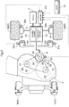
Fig. 2 is a power system diagram of the riding grass mowing machine, -
Fig.3 is a plan view of a mower unit, -
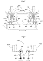
Fig. 4 is a plan view schematically showing relation between a coupling mechanism and an operation of a second pedal for displacing the mower unit to the right side, -
Fig. 5 is a plan view schematically showing relation between a coupling mechanism and an operation of a first pedal for displacing the mower unit to the left side, -
Fig. 6 is an explanatory view schematically showing a displacement operation mechanism consisting of an operational unit and a displacement conversion mechanism, -
Fig. 7 is an explanatory view schematically showing movements of the displacement operation mechanism consisting of the operational unit and the displacement conversion mechanism and a coupling mechanism, -
Fig. 8 is an explanatory view schematically showing movements of a first pedal, a second pedal and the displacement conversion mechanism, and -
Fig. 9 is a perspective view of a riding grass mowing machine relating to a further embodiment. - With reference to the accompanying drawings, there will be explained a mid-mount type riding grass mowing machine mounting a mower unit according to one embodiment of the present invention.
Fig.1 shows a left side view of the grass mowing machine. Here, unless explicitly indicated otherwise, the term "front" means the front side in relation to a machine (vehicle) body front/rear direction (traveling direction), the term "rear" means the rear side in relation to the machine body front/rear direction (traveling direction). Further, the left/right direction or the lateral direction refers to the machine body width direction which is orthogonal to the machine body front/rear direction. The terms "upper" and "lower" refer to positional relations in the perpendicular (vertical) direction of the machine body, representing the relation in connection with the ground height or clearance. - This grass mowing machine includes a
vehicle body frame 10 supported via afront wheel unit 1 and adrive wheel unit 2, abattery 7, a driver'sseat 11, and aROPS frame 12. Thefront wheel unit 1 includes a leftfront wheel 1a and a rightfront wheel 1b. The leftfront wheel 1a and the rightfront wheel 1b are freely rotatable caster type wheels. Thedrive wheel unit 2 includes a leftrear wheel 2a and a rightrear wheel 2b. Thebattery 7 is disposed at a rear portion of thevehicle body frame 10. The driver'sseat 11 is disposed on more front side than thebattery 7. TheROPS frame 12 is mounted erect upward at a position in thevehicle body frame 10 and between the driver'sseat 11 and thebattery 7. Under thevehicle body frame 10, amower deck 30 is provided in a space between thefront wheel unit 1 and thedrive wheel unit 2. Thismower deck 30 constitutes amower unit 3. - Forwardly of the driver's
seat 11, afloor plate 14 is formed. Thefloor plate 14 acts as a "footrest" for the driver. On the left and right opposed sides across the driver'sseat 11, there are disposed a pair of left andright steering units 15. The left andright steering units 15 consist of aleft steering lever 15a and aright steering lever 15b. Theleft steering lever 15a and theright steering lever 15b respectively is pivotable about a horizontal axis extending in the vehicle body lateral or transverse direction. - As shown in
Fig. 1 andFig. 2 , themower unit 3 is configured as a "side-discharge" type unit, and themower unit 3 includes themower deck 30 and tworotary cutter blades 20. A pair ofrotary shafts 21 corresponding respectively to the tworotary cutter blades 20 extend downwards through atop wall 31 of themower deck 30. The pair ofrotary shafts 21 are rotatably supported to thetop wall 31 via bearings. At the respective lower ends of therespective rotary shafts 21, therotary cutter blades 20 are fixed. - Each
rotary cutter blade 20 is rotated by a mowerelectric motor 8. This mowerelectric motor 8 has a flattened shape. Anoutput pulley 24 is attached to the leading end of anoutput shaft 8a of the mowerelectric motor 8. Further, in eachrotary shaft 21, at a portion thereof located upwardly of thetop wall 31, aninput pulley 22 is attached. And, abelt 25 is wound around and across the two input pulleys 22, asingle tension pulley 23 and the oneoutput pulley 24. - As shown in
Fig. 2 , the leftrear wheel 2a is rotatably driven by aleft motor 81 and the rightrear wheel 2b is rotatably driven by aright motor 82. Theleft motor 81 and theright motor 82 function as "traveling electric motors". Aninverter section 70 is configured to be able to feed electric power to theleft motor 81 and theright motor 82 and the mowerelectric motor 8. Theinverter section 70 includes a travelinginverter 71 and an implementinverter 72. The travelinginverter 71 feeds power to theleft motor 81 and theright motor 82. The implementinverter 72 feeds power to the mowerelectric motor 8. Theinverter section 70 drives based on control signals from a controller CU. - To the controller CU, there are connected a mower
operational tool 16, a left steeringangle detection sensor 91a, a right steeringangle detection sensor 91b, a leftrotation detection sensor 92a, a rightrotation detection sensor 92b, and a mowerrotational speed sensor 93. The moweroperational tool 16 is used for effecting ON/OFF operations and rotational speed adjustment operation of the mowerelectric motor 8. The left steeringangle detection sensor 91a detects a pivotal angle of theleft steering lever 15a. The right steeringangle detection sensor 91b detects a pivotal angle of theright steering lever 15b. The leftrotation detection sensor 92a detects a rotational speed of theleft motor 81. The rightrotation detection sensor 92b detects a rotational speed of theright motor 82. The mowerrotational speed sensor 93 detects a rotational speed of the mowerelectric motor 8. - Based on a pivotal angle of the
left steering lever 15a detected by the left steeringangle detection sensor 91a, the controller CU calculates the rotational speed of the leftrear wheel 2a, namely, calculates a rotational speed of theleft motor 81. Based on a pivotal angle of theright steering lever 15b detected by the right steeringangle detection sensor 91b, the controller CU calculates the rotational speed of the rightrear wheel 2b, namely, calculates a rotational speed of theright motor 82. Then, the controller CU outputs control signals for rotational speeds respectively of theleft motor 81 and theright motor 82 to the travelinginverter 71. The travelinginverter 71 is configured to be capable of outputting electric powers independently to theleft motor 81 and theright motor 82. And, by feeding different power values to theleft motor 81 and theright motor 82, the travelinginverter 71 can make the respective rotational speeds of the leftrear wheel 2a and the rightrear wheel 2b different from each other. And, based on a speed difference between the leftrear wheel 2a and the rightrear wheel 2b, a turning of the grass mowing machine is performed. - As shown in
Fig. 3 , themower deck 30 includes thetop wall 31 and afront wall 32 and arear wall 33 which extend downward from the outer circumferential edge of thetop wall 31. Thefront wall 32 is continuous with the front side outer circumferential edge of thetop wall 31 and therear wall 33 is continuous with the rear side outer circumferential edge. Right end areas of thefront wall 32 and therear wall 33 are cutaway, thus creating a cutgrass discharge outlet 35 covered by acover 34. Thetop wall 31, thefront wall 32 and therear wall 33 together form a space inside themower deck 30. In this inner space, the tworotary cutter blades 20 are disposed in juxtaposition along the vehicle body transverse direction. - As shown in
Fig. 1 , themower deck 30 is suspended from thevehicle body frame 10 to be liftable up/down via asuspension mechanism 4 which functions as a "coupling mechanism" for operably coupling themower deck 30 to thevehicle body frame 10. Further, themower deck 30 is laterally displaceable in the vehicle body transverse direction by a displacement operation mechanism MV. - Schematic arrangements of the
suspension mechanism 4 and the displacement operation mechanism MV are shown inFigs. 4 through 8 . Thesuspension mechanism 4, as shown inFig. 1 , is a parallel crank mechanism employed in conventional grass mowing machines. However, unlike the convention, thissuspension mechanism 4 is capable of not only lifting up/down themower deck 30, but also displacing thismower deck 30 in the vehicle body transverse direction. Thesuspension mechanism 4, as shown inFig. 6 , includes four link units. Each link unit includes amower bracket 41 fixed to themower deck 30, avehicle body bracket 42 fixed to thevehicle body frame 10, and amower link 43 operably coupling themower bracket 41 with thevehicle body bracket 42. Thevehicle body bracket 42 and themower link 43 are connected via anupper link pin 44. Themower bracket 41 and themower link 43 are connected via alower link pin 45. The leftfront mower link 43 and the leftrear mower link 43 are connected via aconnection rod 40. The rightfront mower link 43 and the rightrear mower link 43 are connected via aconnection rod 40. - In the example shown in
Fig. 6 , as the rear mower links 43 are operated by a hydraulic or electric lift cylinder SY, themower deck 30 is lifted up/down. The point of action of the lift cylinder SY on the link unit may be other than the rear mower links 43. Needless to say, lifting up/down of themower deck 30 may be carried out manually also without using the lift cylinder SY. - The mower links 43 of the
suspension mechanism 4, in order to enable the displacement of themower deck 30 in the vehicle body transverse direction, consists of amain link 431 and an angle-shapedauxiliary link 432, as shown inFig. 7 . Theauxiliary link 432 is fixed to themain link 431 in such a manner as to secure a free space FS in the vehicle body transverse direction between themain link 431 and theauxiliary link 432. Themain link 431, theauxiliary link 432 and themower bracket 41 are pin-connected to each other. Here, themain link 431, theauxiliary link 432 and themower bracket 41 are coupled to be pivotable relative to each other by alower link pin 45 which extends through holes formed respectively therein, with a positional relationship of a vertical piece of themower bracket 41 entering the free space FS of themower link 43. Therefore, the length of thelower link pin 45 is greater than the length of the free space FS in the vehicle body transverse direction. With this arrangement, themower deck 30 is able to be laterally displaced in the vehicle body transverse direction substantially by the distance between themain link 431 and theauxiliary link 432. - As shown in
Fig. 7 and also inFig. 8 which is more schematic than theFig. 7 illustration, the displacement operation mechanism MV includes anoperational unit 5 supported to thevehicle body frame 10 and adisplacement conversion mechanism 6 including adisplacement conversion section 60 for converting an operational displacement of theoperational unit 5 to a lateral displacement of themower deck 30. Incidentally, in the instant embodiment, theoperational unit 5 is constituted of a pedal unit operable by a driver's foot. And, this pedal unit consists of afirst pedal 51 and asecond pedal 52. Therefore, operational displacements for laterally displacing themower deck 30 are stepping-on displacements of thefirst pedal 51 and thesecond pedal 52. Thedisplacement conversion section 60 converts an operational displacement into an operational displacement needed for a lateral displacement of themower deck 30. - The
displacement conversion mechanism 6 is divided into a leftdisplacement conversion mechanism 6 and a rightdisplacement conversion mechanism 6. The leftdisplacement conversion mechanism 6 utilizes an operational displacement of thefirst pedal 51 for a lateral displacement in first direction (left displacement) of themower deck 30. The rightdisplacement conversion mechanism 6 utilizes an operational displacement of thesecond pedal 52 for a lateral displacement in second direction (right displacement) of themower deck 30. The arrangements of these two mechanisms are essentially identical. Thus, in the following discussion, the leftdisplacement conversion mechanism 6 will be explained as being representative of both. - The left
displacement conversion mechanism 6 further includes a firstdisplacement transmission member 61 and a seconddisplacement transmission member 62. The firstdisplacement transmission member 61 is a shaft body operably coupled with apedal shaft 53 of thefirst pedal 51 and configured to transmit a displacement of thepedal shaft 53 to thedisplacement conversion section 60. Thedisplacement conversion section 60 is constituted of a gear, a cam or any combination thereof and configured to convert an inputted displacement to a pivotal displacement in the vehicle body transverse direction (first direction: left displacement) and to output the resultant pivotal displacement. The seconddisplacement transmission member 62 is a pivot arm. the leading end of the seconddisplacement transmission member 62 is operably coupled to or placed in abutment against adisplacement action portion 63 fixed to themower deck 30. The seconddisplacement transmission member 62 is configured to transmit a pivotal displacement which is an action displacement outputted from thedisplacement conversion section 60 to thedisplacement action portion 63, thereby to laterally displace thedisplacement action portion 63, namely, themower deck 30 to the left side. - With the above-described arrangement of the displacement operation mechanism MV in operation, when the driver steps on the
first pedal 51 which is the left pedal, themower deck 30 is laterally displaced to the left side and the grass mowing path is offset to the left side. Similarly, when the driver steps on thesecond pedal 52 which is the right pedal, themower deck 30 is laterally displaced to the right side and the grass mowing path is offset to the right side. - The present invention is not limited to the arrangement illustrated in the above embodiment. Next, other embodiments of the present invention will be described one by one.
- (1) In the foregoing embodiment the
operational unit 5 is configured as a pedal unit consisting of thefirst pedal 51 and thesecond pedal 52. Instead of this, thisunit 5 may be constituted of a single pedal. In this case, there will be provided a stopper for maintaining a stepped-on position of the single pedal. Then, in accordance with a stepping-on of the single pedal, themower deck 30 will be laterally displaced to the left side and when the single pedal is returned to the home position (the position prior to the stepping-on operation), themower deck 30 will be laterally displaced to the right side by an action of an urging means such as a spring. - (2) The
operational unit 5 may be constituted of a handle lever unit operable by a driver's hand, rather than a pedal unit. - (3) The displacement operation mechanism MV may comprise a ball screw mechanism configured to convert a rotation of the
operational unit 5 to a lateral displacement of themower deck 30. - (4) In the foregoing embodiment, the
mower deck 30 is disposed between thefront wheel unit 1 as front wheels and thedrive wheel unit 2 as rear wheels. Alternatively, themower deck 30 may be disposed forwardly of the front wheels or rearwardly of the rear wheels. - (5) In the foregoing embodiment, as the
steering unit 15, there was employed a lever operation mechanism consisting of an elongateleft steering lever 15a and an elongateright steering lever 15b. Instead of this, as this unit, a joystick operation mechanism having a short lever may be employed, as shown inFig. 9 . In the example illustrated inFig. 9 , the joystick operation mechanism consists of aleft joystick 9a and aright joystick 9b provided at the leading end regions of aleft armrest 11a and aright armrest 11b of the driver'sseat 11 via abase 90. Thebase 90 is adjustable to the front and rear sides, left and right sides and upper and lower sides, so joystick operations are possible at various positions suited for the driver's preference. In this example, pivotal movements of theleft joystick 9a and theright joystick 9b in the front/rear direction alone are utilized for adjustment of rotational speeds (forward traveling and reverse traveling) of thedrive wheel unit 2. In place of this, in case displacements of the joysticks in the front/rear direction and left/right direction are utilized, the joystick operation mechanism will be constituted of a single joystick and the grass mowing machine will be moved into a tilted direction of the joystick. - Incidentally, the arrangements disclosed in the foregoing embodiments (including the further embodiments) may be used in any combinations with the arrangements disclosed in any other embodiment unless contradiction results from such combinations. Further, it is noted that the embodiments disclosed in this detailed disclosure are only exemplary and embodiments of the present invention are not limited thereto, but may be modified in any appropriate matter within a range not deviating from the object of the present invention as defined by the claims.
- The present invention is applicable to a grass mowing machine having a mower unit including an electrically driven cutter blade.
Claims (7)
- A grass mowing machine comprising:a vehicle body frame (10) supported on a ground surface via a wheel unit;a mower deck (30) incorporating a rotary cutter blade (20);a coupling mechanism for coupling the mower deck (30) to the vehicle body frame (10) with allowing a lateral displacement of the mower deck (30) in a vehicle body transverse direction;a mower electric motor attached to the mower deck (30) and configured to feed rotary power to the rotary cutter blade (20); anda displacement operation mechanism (MV) for laterally displacing the mower deck (30) in the vehicle body transverse direction in operative association with the coupling mechanism.
- The grass mowing machine of claim 1, wherein the coupling mechanism comprises a suspension mechanism (4) for suspending the mower deck (30) from the vehicle body frame (10).
- The grass mowing machine of claim 2, wherein:the suspension mechanism (4) includes a vehicle body bracket (42) fixed to the vehicle body frame (10) and a mower bracket (41) fixed to the mower deck (30) and a mower link (43) coupled by a pin coupling to the vehicle body bracket (42) and the mower bracket (41); andthe pin coupling is configured to allow a lateral displacement of the mower bracket (41) in the vehicle body transverse direction relative to the vehicle body frame (10).
- The grass mowing machine of any one of claims 1-3, wherein the displacement operation mechanism (MV) includes an operational unit (5) supported to the vehicle body frame (10) and a displacement conversion mechanism (6) for converting an operational displacement of the operational unit (5) to a lateral displacement of the mower deck (30).
- The grass mowing machine of claim 4, wherein the operational unit (5) comprises a pedal unit operated by a driver's foot and the operational displacement comprises a step-on displacement of a pedal.
- The grass mowing machine of claim 5, wherein:the pedal unit includes a first pedal (51) and a second pedal (52); andthe displacement conversion mechanism (6) is configured to convert a step-on displacement of the first pedal (51) into a lateral displacement in one direction of the mower deck (30) and to convert a step-on displacement of the second pedal (52) into a lateral displacement in the other direction of the mower deck (30).
- The grass mowing machine of any one of claims 1-6, wherein the grass mowing machine is configured such that its traveling drive power is fed by a traveling electric motor.
Applications Claiming Priority (1)
| Application Number | Priority Date | Filing Date | Title |
|---|---|---|---|
| JP2019093691A JP7157001B2 (en) | 2019-05-17 | 2019-05-17 | lawn mower |
Publications (2)
| Publication Number | Publication Date |
|---|---|
| EP3738424A1 true EP3738424A1 (en) | 2020-11-18 |
| EP3738424B1 EP3738424B1 (en) | 2024-03-20 |
Family
ID=70738276
Family Applications (1)
| Application Number | Title | Priority Date | Filing Date |
|---|---|---|---|
| EP20174800.1A Active EP3738424B1 (en) | 2019-05-17 | 2020-05-14 | Grass mowing machine |
Country Status (3)
| Country | Link |
|---|---|
| US (1) | US11700790B2 (en) |
| EP (1) | EP3738424B1 (en) |
| JP (1) | JP7157001B2 (en) |
Cited By (4)
| Publication number | Priority date | Publication date | Assignee | Title |
|---|---|---|---|---|
| US20220312673A1 (en) * | 2021-04-01 | 2022-10-06 | Kubota Corporation | Mower Unit |
| EP4140276A1 (en) | 2021-08-31 | 2023-03-01 | Stiga S.p.A. in breve anche St. S.p.A. | Mobile device comprising a handlebar with capability of variation of its inclination |
| EP4140281A1 (en) | 2021-08-31 | 2023-03-01 | Stiga S.p.A. in breve anche St. S.p.A. | Mobile device with an articulation system effective between an operating body and a support frame and with an obstacle detector functionally connected to an actuator of the articulation system |
| EP4140277A1 (en) | 2021-08-31 | 2023-03-01 | Stiga S.p.A. in breve anche St. S.p.A. | Land maintenance device |
Families Citing this family (8)
| Publication number | Priority date | Publication date | Assignee | Title |
|---|---|---|---|---|
| US10455826B2 (en) | 2018-02-05 | 2019-10-29 | FarmWise Labs, Inc. | Method for autonomously weeding crops in an agricultural field |
| US12201044B2 (en) | 2018-02-05 | 2025-01-21 | FarmWise Labs, Inc. | Method for autonomously weeding crops in an agricultural field |
| DE112019001956T5 (en) * | 2018-04-13 | 2021-01-21 | Dana Heavy Vehicle Systems Group, Llc | SUPPORT DEVICE FOR A LOAD OFFSET ON A WHEEL AXLE |
| TWI874522B (en) | 2020-03-27 | 2025-03-01 | 大陸商石家莊誠志永華顯示材料有限公司 | Liquid crystal composition, liquid crystal display element and compound |
| JP2023004671A (en) | 2021-06-28 | 2023-01-17 | 株式会社クボタ | riding lawn mower |
| US11993323B2 (en) * | 2021-09-03 | 2024-05-28 | Firefly Automatix, Inc. | Steering system for a mower |
| US12120973B2 (en) | 2023-02-07 | 2024-10-22 | FarmWise Labs, Inc. | Crop detection system and/or method |
| WO2025037292A1 (en) * | 2023-08-16 | 2025-02-20 | Multihog R& D Limited | A wheeled work vehicle |
Citations (6)
| Publication number | Priority date | Publication date | Assignee | Title |
|---|---|---|---|---|
| DE4407812A1 (en) * | 1994-03-09 | 1995-09-14 | Popiolek Franz M | Drum mower for agricultural crops |
| US6223510B1 (en) * | 1999-06-08 | 2001-05-01 | Gary L. Gillins | Mower deck with object tracing capability |
| FR2900023A1 (en) * | 2007-05-31 | 2007-10-26 | Gyrax Soc Par Actions Simplifi | Vegetable grinder for being hooked to tractor, has protection shield that is mounted on lateral grinding modules for pivoting connecting rod along axis parallel to articulation axis of grinding modules |
| WO2010140929A1 (en) * | 2009-06-01 | 2010-12-09 | Andersson, Jonas | Lawn mower |
| JP2017035029A (en) | 2015-08-10 | 2017-02-16 | 株式会社ササキコーポレーション | Mowing machine |
| CN109526402A (en) * | 2018-12-06 | 2019-03-29 | 宁波朗辉工具有限公司 | A lawn mower folding chassis |
Family Cites Families (19)
| Publication number | Priority date | Publication date | Assignee | Title |
|---|---|---|---|---|
| US3706186A (en) * | 1971-07-07 | 1972-12-19 | Sperry Rand Corp | Suspension system for a mower unit |
| JPS568221U (en) | 1979-06-29 | 1981-01-24 | ||
| US4893456A (en) * | 1988-04-21 | 1990-01-16 | Wallace Robert H | Tractor with shiftable mowing deck |
| US5085044A (en) * | 1990-09-24 | 1992-02-04 | Simplicity Manufacturing, Inc. | Two-blade mower deck with infinite height adjustment |
| JPH0568221U (en) * | 1992-02-25 | 1993-09-17 | セイレイ工業株式会社 | Mower mounting structure for lawn mower |
| US5483789A (en) * | 1994-04-22 | 1996-01-16 | Gummerson; Elwyn W. | Laterally movable grass cutting mower attachment |
| US5502957A (en) * | 1995-03-29 | 1996-04-02 | Robertson; Charles W. | Electric lawn mower with intelligent control |
| US6584756B2 (en) * | 2001-06-20 | 2003-07-01 | Deere & Company | Pivoting hooks for parallelogram lift linkages |
| US7059107B2 (en) * | 2003-12-10 | 2006-06-13 | Vincent Pulvirenti | Multi-purpose lawn assembly |
| US7240470B2 (en) * | 2005-07-21 | 2007-07-10 | Deere & Company | Drive over mower deck |
| US7587886B1 (en) * | 2007-12-28 | 2009-09-15 | Scag Power Equipment, Inc. | Lawnmower with cutter deck locator assembly |
| US7669394B2 (en) * | 2008-01-20 | 2010-03-02 | Exmark Mfg. Co., Inc. | Propulsion and stabilization struts for mower cutting deck |
| EP2389797B1 (en) * | 2010-05-27 | 2014-11-19 | Kanzaki Kokyukoki Mfg. Co., Ltd. | Electric lawn mower |
| EP2574160B1 (en) * | 2010-06-16 | 2017-03-01 | Husqvarna AB | Light riding vehicle |
| JP5615730B2 (en) | 2011-02-17 | 2014-10-29 | ヤンマー株式会社 | Electric riding mower |
| JP5860380B2 (en) * | 2012-10-30 | 2016-02-16 | ヤンマー株式会社 | Shift operation mechanism and work vehicle |
| WO2014203422A1 (en) * | 2013-06-19 | 2014-12-24 | ヤンマー株式会社 | Electric work vehicle |
| US9622406B2 (en) * | 2013-12-27 | 2017-04-18 | Kubota Corporation | Mid-mount mower with power transmission coupling |
| JP6509060B2 (en) | 2015-07-13 | 2019-05-08 | 株式会社クボタ | Mowing machine |
-
2019
- 2019-05-17 JP JP2019093691A patent/JP7157001B2/en active Active
-
2020
- 2020-05-13 US US15/930,534 patent/US11700790B2/en active Active
- 2020-05-14 EP EP20174800.1A patent/EP3738424B1/en active Active
Patent Citations (6)
| Publication number | Priority date | Publication date | Assignee | Title |
|---|---|---|---|---|
| DE4407812A1 (en) * | 1994-03-09 | 1995-09-14 | Popiolek Franz M | Drum mower for agricultural crops |
| US6223510B1 (en) * | 1999-06-08 | 2001-05-01 | Gary L. Gillins | Mower deck with object tracing capability |
| FR2900023A1 (en) * | 2007-05-31 | 2007-10-26 | Gyrax Soc Par Actions Simplifi | Vegetable grinder for being hooked to tractor, has protection shield that is mounted on lateral grinding modules for pivoting connecting rod along axis parallel to articulation axis of grinding modules |
| WO2010140929A1 (en) * | 2009-06-01 | 2010-12-09 | Andersson, Jonas | Lawn mower |
| JP2017035029A (en) | 2015-08-10 | 2017-02-16 | 株式会社ササキコーポレーション | Mowing machine |
| CN109526402A (en) * | 2018-12-06 | 2019-03-29 | 宁波朗辉工具有限公司 | A lawn mower folding chassis |
Cited By (12)
| Publication number | Priority date | Publication date | Assignee | Title |
|---|---|---|---|---|
| US20220312673A1 (en) * | 2021-04-01 | 2022-10-06 | Kubota Corporation | Mower Unit |
| EP4140276A1 (en) | 2021-08-31 | 2023-03-01 | Stiga S.p.A. in breve anche St. S.p.A. | Mobile device comprising a handlebar with capability of variation of its inclination |
| EP4140281A1 (en) | 2021-08-31 | 2023-03-01 | Stiga S.p.A. in breve anche St. S.p.A. | Mobile device with an articulation system effective between an operating body and a support frame and with an obstacle detector functionally connected to an actuator of the articulation system |
| EP4140280A1 (en) | 2021-08-31 | 2023-03-01 | Stiga S.p.A. in breve anche St. S.p.A. | Mobile device with an articulation system effective between an operating body and a support frame and with an actuation system functionally connected to the articulation system |
| EP4140277A1 (en) | 2021-08-31 | 2023-03-01 | Stiga S.p.A. in breve anche St. S.p.A. | Land maintenance device |
| IT202100022616A1 (en) * | 2021-08-31 | 2023-03-03 | Stiga S P A In Breve Anche St S P A | MOBILE DEVICE EQUIPPED WITH MEANS FOR ADJUSTING THE POSITION OF A PAYLOAD, IN PARTICULAR A GRASS CUTTING UNIT |
| EP4165975A1 (en) | 2021-08-31 | 2023-04-19 | Stiga S.p.A. in breve anche St. S.p.A. | Mobile device with an articulation system effective between an operating body and a support frame and with a flexible duct interposed between the operating body and the support frame |
| EP4368009A1 (en) | 2021-08-31 | 2024-05-15 | Stiga S.p.A. in breve anche St. S.p.A. | Mobile device with an effective articulation system between an operating body and a support frame and with a flexible conduit interposed between the operating body and the support frame |
| EP4595738A2 (en) | 2021-08-31 | 2025-08-06 | Stiga S.p.A. in breve anche St. S.p.A. | Self-driving mobile device having an operating body housing a work tool and movable along a translation axis |
| EP4599660A2 (en) | 2021-08-31 | 2025-08-13 | Stiga S.p.A. in breve anche St. S.p.A. | Mobile device with an articulation system effective between an operating body and a support frame and with an actuation system functionally connected to the articulation system |
| EP4595738A3 (en) * | 2021-08-31 | 2025-11-12 | Stiga S.p.A. in breve anche St. S.p.A. | Self-driving mobile device having an operating body housing a work tool and movable along a translation axis |
| EP4599660A3 (en) * | 2021-08-31 | 2026-02-18 | Stiga S.p.A. in breve anche St. S.p.A. | Mobile device with an articulation system effective between an operating body and a support frame and with an actuation system functionally connected to the articulation system |
Also Published As
| Publication number | Publication date |
|---|---|
| JP7157001B2 (en) | 2022-10-19 |
| EP3738424B1 (en) | 2024-03-20 |
| JP2020184970A (en) | 2020-11-19 |
| US20200359565A1 (en) | 2020-11-19 |
| US11700790B2 (en) | 2023-07-18 |
Similar Documents
| Publication | Publication Date | Title |
|---|---|---|
| EP3738424B1 (en) | Grass mowing machine | |
| US8490722B2 (en) | Riding-type ground working vehicle | |
| US5913802A (en) | Single lever drivewheel steering power lawn mower | |
| EP3501947B1 (en) | Electrically powered work vehicle | |
| US5337543A (en) | Lawn mower for use both as riding and walking operator type | |
| EP3777507A1 (en) | Work vehicle and grass mowing machine | |
| US10645873B2 (en) | Grass mower | |
| US9750184B2 (en) | Mower deck with tilted idle pulleys | |
| EP4111847A1 (en) | Riding grass mower | |
| US7159343B2 (en) | Working machine | |
| CA2227539C (en) | Brake for self-propelled vehicle | |
| US4147227A (en) | Standard model tractor with removable second set of operating controls | |
| GB2627341A (en) | Zero turning radius mower steering sensor linkage | |
| US6367574B1 (en) | Multi-function control system for articulated vehicle | |
| EP3504955B1 (en) | Grass mower | |
| JP6976226B2 (en) | Work platform | |
| US12464980B2 (en) | Compaction roller for working machine | |
| JP2021004586A (en) | Work vehicle | |
| JPS6230501Y2 (en) | ||
| JP2008239031A (en) | Traveling vehicle | |
| JPS6323224Y2 (en) | ||
| JP3567646B2 (en) | Rice transplanter | |
| WO2021176266A1 (en) | Electrically powered, universal accessory drive | |
| JP2003274730A (en) | Mower elevating structure of work machine | |
| JP2008239032A (en) | Traveling vehicle |
Legal Events
| Date | Code | Title | Description |
|---|---|---|---|
| PUAI | Public reference made under article 153(3) epc to a published international application that has entered the european phase |
Free format text: ORIGINAL CODE: 0009012 |
|
| STAA | Information on the status of an ep patent application or granted ep patent |
Free format text: STATUS: REQUEST FOR EXAMINATION WAS MADE |
|
| 17P | Request for examination filed |
Effective date: 20200514 |
|
| AK | Designated contracting states |
Kind code of ref document: A1 Designated state(s): AL AT BE BG CH CY CZ DE DK EE ES FI FR GB GR HR HU IE IS IT LI LT LU LV MC MK MT NL NO PL PT RO RS SE SI SK SM TR |
|
| AX | Request for extension of the european patent |
Extension state: BA ME |
|
| GRAP | Despatch of communication of intention to grant a patent |
Free format text: ORIGINAL CODE: EPIDOSNIGR1 |
|
| STAA | Information on the status of an ep patent application or granted ep patent |
Free format text: STATUS: GRANT OF PATENT IS INTENDED |
|
| INTG | Intention to grant announced |
Effective date: 20231016 |
|
| RIN1 | Information on inventor provided before grant (corrected) |
Inventor name: YASUE, FUMIYA Inventor name: YAMADA, MASAHIRO |
|
| GRAS | Grant fee paid |
Free format text: ORIGINAL CODE: EPIDOSNIGR3 |
|
| GRAA | (expected) grant |
Free format text: ORIGINAL CODE: 0009210 |
|
| STAA | Information on the status of an ep patent application or granted ep patent |
Free format text: STATUS: THE PATENT HAS BEEN GRANTED |
|
| AK | Designated contracting states |
Kind code of ref document: B1 Designated state(s): AL AT BE BG CH CY CZ DE DK EE ES FI FR GB GR HR HU IE IS IT LI LT LU LV MC MK MT NL NO PL PT RO RS SE SI SK SM TR |
|
| REG | Reference to a national code |
Ref country code: GB Ref legal event code: FG4D |
|
| REG | Reference to a national code |
Ref country code: CH Ref legal event code: EP |
|
| REG | Reference to a national code |
Ref country code: DE Ref legal event code: R096 Ref document number: 602020027402 Country of ref document: DE |
|
| REG | Reference to a national code |
Ref country code: IE Ref legal event code: FG4D |
|
| PG25 | Lapsed in a contracting state [announced via postgrant information from national office to epo] |
Ref country code: LT Free format text: LAPSE BECAUSE OF FAILURE TO SUBMIT A TRANSLATION OF THE DESCRIPTION OR TO PAY THE FEE WITHIN THE PRESCRIBED TIME-LIMIT Effective date: 20240320 |
|
| REG | Reference to a national code |
Ref country code: LT Ref legal event code: MG9D |
|
| PG25 | Lapsed in a contracting state [announced via postgrant information from national office to epo] |
Ref country code: GR Free format text: LAPSE BECAUSE OF FAILURE TO SUBMIT A TRANSLATION OF THE DESCRIPTION OR TO PAY THE FEE WITHIN THE PRESCRIBED TIME-LIMIT Effective date: 20240621 |
|
| PG25 | Lapsed in a contracting state [announced via postgrant information from national office to epo] |
Ref country code: RS Free format text: LAPSE BECAUSE OF FAILURE TO SUBMIT A TRANSLATION OF THE DESCRIPTION OR TO PAY THE FEE WITHIN THE PRESCRIBED TIME-LIMIT Effective date: 20240620 Ref country code: HR Free format text: LAPSE BECAUSE OF FAILURE TO SUBMIT A TRANSLATION OF THE DESCRIPTION OR TO PAY THE FEE WITHIN THE PRESCRIBED TIME-LIMIT Effective date: 20240320 |
|
| REG | Reference to a national code |
Ref country code: NL Ref legal event code: MP Effective date: 20240320 |
|
| PG25 | Lapsed in a contracting state [announced via postgrant information from national office to epo] |
Ref country code: RS Free format text: LAPSE BECAUSE OF FAILURE TO SUBMIT A TRANSLATION OF THE DESCRIPTION OR TO PAY THE FEE WITHIN THE PRESCRIBED TIME-LIMIT Effective date: 20240620 Ref country code: NO Free format text: LAPSE BECAUSE OF FAILURE TO SUBMIT A TRANSLATION OF THE DESCRIPTION OR TO PAY THE FEE WITHIN THE PRESCRIBED TIME-LIMIT Effective date: 20240620 Ref country code: LT Free format text: LAPSE BECAUSE OF FAILURE TO SUBMIT A TRANSLATION OF THE DESCRIPTION OR TO PAY THE FEE WITHIN THE PRESCRIBED TIME-LIMIT Effective date: 20240320 Ref country code: HR Free format text: LAPSE BECAUSE OF FAILURE TO SUBMIT A TRANSLATION OF THE DESCRIPTION OR TO PAY THE FEE WITHIN THE PRESCRIBED TIME-LIMIT Effective date: 20240320 Ref country code: GR Free format text: LAPSE BECAUSE OF FAILURE TO SUBMIT A TRANSLATION OF THE DESCRIPTION OR TO PAY THE FEE WITHIN THE PRESCRIBED TIME-LIMIT Effective date: 20240621 Ref country code: FI Free format text: LAPSE BECAUSE OF FAILURE TO SUBMIT A TRANSLATION OF THE DESCRIPTION OR TO PAY THE FEE WITHIN THE PRESCRIBED TIME-LIMIT Effective date: 20240320 Ref country code: BG Free format text: LAPSE BECAUSE OF FAILURE TO SUBMIT A TRANSLATION OF THE DESCRIPTION OR TO PAY THE FEE WITHIN THE PRESCRIBED TIME-LIMIT Effective date: 20240320 |
|
| REG | Reference to a national code |
Ref country code: AT Ref legal event code: MK05 Ref document number: 1666961 Country of ref document: AT Kind code of ref document: T Effective date: 20240320 |
|
| PG25 | Lapsed in a contracting state [announced via postgrant information from national office to epo] |
Ref country code: SE Free format text: LAPSE BECAUSE OF FAILURE TO SUBMIT A TRANSLATION OF THE DESCRIPTION OR TO PAY THE FEE WITHIN THE PRESCRIBED TIME-LIMIT Effective date: 20240320 Ref country code: LV Free format text: LAPSE BECAUSE OF FAILURE TO SUBMIT A TRANSLATION OF THE DESCRIPTION OR TO PAY THE FEE WITHIN THE PRESCRIBED TIME-LIMIT Effective date: 20240320 |
|
| PG25 | Lapsed in a contracting state [announced via postgrant information from national office to epo] |
Ref country code: NL Free format text: LAPSE BECAUSE OF FAILURE TO SUBMIT A TRANSLATION OF THE DESCRIPTION OR TO PAY THE FEE WITHIN THE PRESCRIBED TIME-LIMIT Effective date: 20240320 |
|
| PG25 | Lapsed in a contracting state [announced via postgrant information from national office to epo] |
Ref country code: NL Free format text: LAPSE BECAUSE OF FAILURE TO SUBMIT A TRANSLATION OF THE DESCRIPTION OR TO PAY THE FEE WITHIN THE PRESCRIBED TIME-LIMIT Effective date: 20240320 |
|
| PG25 | Lapsed in a contracting state [announced via postgrant information from national office to epo] |
Ref country code: IS Free format text: LAPSE BECAUSE OF FAILURE TO SUBMIT A TRANSLATION OF THE DESCRIPTION OR TO PAY THE FEE WITHIN THE PRESCRIBED TIME-LIMIT Effective date: 20240720 |
|
| PG25 | Lapsed in a contracting state [announced via postgrant information from national office to epo] |
Ref country code: PT Free format text: LAPSE BECAUSE OF FAILURE TO SUBMIT A TRANSLATION OF THE DESCRIPTION OR TO PAY THE FEE WITHIN THE PRESCRIBED TIME-LIMIT Effective date: 20240722 Ref country code: SM Free format text: LAPSE BECAUSE OF FAILURE TO SUBMIT A TRANSLATION OF THE DESCRIPTION OR TO PAY THE FEE WITHIN THE PRESCRIBED TIME-LIMIT Effective date: 20240320 |
|
| PG25 | Lapsed in a contracting state [announced via postgrant information from national office to epo] |
Ref country code: ES Free format text: LAPSE BECAUSE OF FAILURE TO SUBMIT A TRANSLATION OF THE DESCRIPTION OR TO PAY THE FEE WITHIN THE PRESCRIBED TIME-LIMIT Effective date: 20240320 |
|
| PG25 | Lapsed in a contracting state [announced via postgrant information from national office to epo] |
Ref country code: CZ Free format text: LAPSE BECAUSE OF FAILURE TO SUBMIT A TRANSLATION OF THE DESCRIPTION OR TO PAY THE FEE WITHIN THE PRESCRIBED TIME-LIMIT Effective date: 20240320 Ref country code: EE Free format text: LAPSE BECAUSE OF FAILURE TO SUBMIT A TRANSLATION OF THE DESCRIPTION OR TO PAY THE FEE WITHIN THE PRESCRIBED TIME-LIMIT Effective date: 20240320 |
|
| PG25 | Lapsed in a contracting state [announced via postgrant information from national office to epo] |
Ref country code: AT Free format text: LAPSE BECAUSE OF FAILURE TO SUBMIT A TRANSLATION OF THE DESCRIPTION OR TO PAY THE FEE WITHIN THE PRESCRIBED TIME-LIMIT Effective date: 20240320 |
|
| PG25 | Lapsed in a contracting state [announced via postgrant information from national office to epo] |
Ref country code: PL Free format text: LAPSE BECAUSE OF FAILURE TO SUBMIT A TRANSLATION OF THE DESCRIPTION OR TO PAY THE FEE WITHIN THE PRESCRIBED TIME-LIMIT Effective date: 20240320 |
|
| PG25 | Lapsed in a contracting state [announced via postgrant information from national office to epo] |
Ref country code: SK Free format text: LAPSE BECAUSE OF FAILURE TO SUBMIT A TRANSLATION OF THE DESCRIPTION OR TO PAY THE FEE WITHIN THE PRESCRIBED TIME-LIMIT Effective date: 20240320 |
|
| PG25 | Lapsed in a contracting state [announced via postgrant information from national office to epo] |
Ref country code: SM Free format text: LAPSE BECAUSE OF FAILURE TO SUBMIT A TRANSLATION OF THE DESCRIPTION OR TO PAY THE FEE WITHIN THE PRESCRIBED TIME-LIMIT Effective date: 20240320 Ref country code: SK Free format text: LAPSE BECAUSE OF FAILURE TO SUBMIT A TRANSLATION OF THE DESCRIPTION OR TO PAY THE FEE WITHIN THE PRESCRIBED TIME-LIMIT Effective date: 20240320 Ref country code: RO Free format text: LAPSE BECAUSE OF FAILURE TO SUBMIT A TRANSLATION OF THE DESCRIPTION OR TO PAY THE FEE WITHIN THE PRESCRIBED TIME-LIMIT Effective date: 20240320 Ref country code: PT Free format text: LAPSE BECAUSE OF FAILURE TO SUBMIT A TRANSLATION OF THE DESCRIPTION OR TO PAY THE FEE WITHIN THE PRESCRIBED TIME-LIMIT Effective date: 20240722 Ref country code: PL Free format text: LAPSE BECAUSE OF FAILURE TO SUBMIT A TRANSLATION OF THE DESCRIPTION OR TO PAY THE FEE WITHIN THE PRESCRIBED TIME-LIMIT Effective date: 20240320 Ref country code: IS Free format text: LAPSE BECAUSE OF FAILURE TO SUBMIT A TRANSLATION OF THE DESCRIPTION OR TO PAY THE FEE WITHIN THE PRESCRIBED TIME-LIMIT Effective date: 20240720 Ref country code: ES Free format text: LAPSE BECAUSE OF FAILURE TO SUBMIT A TRANSLATION OF THE DESCRIPTION OR TO PAY THE FEE WITHIN THE PRESCRIBED TIME-LIMIT Effective date: 20240320 Ref country code: EE Free format text: LAPSE BECAUSE OF FAILURE TO SUBMIT A TRANSLATION OF THE DESCRIPTION OR TO PAY THE FEE WITHIN THE PRESCRIBED TIME-LIMIT Effective date: 20240320 Ref country code: CZ Free format text: LAPSE BECAUSE OF FAILURE TO SUBMIT A TRANSLATION OF THE DESCRIPTION OR TO PAY THE FEE WITHIN THE PRESCRIBED TIME-LIMIT Effective date: 20240320 Ref country code: AT Free format text: LAPSE BECAUSE OF FAILURE TO SUBMIT A TRANSLATION OF THE DESCRIPTION OR TO PAY THE FEE WITHIN THE PRESCRIBED TIME-LIMIT Effective date: 20240320 |
|
| PG25 | Lapsed in a contracting state [announced via postgrant information from national office to epo] |
Ref country code: IT Free format text: LAPSE BECAUSE OF FAILURE TO SUBMIT A TRANSLATION OF THE DESCRIPTION OR TO PAY THE FEE WITHIN THE PRESCRIBED TIME-LIMIT Effective date: 20240320 |
|
| REG | Reference to a national code |
Ref country code: DE Ref legal event code: R097 Ref document number: 602020027402 Country of ref document: DE |
|
| REG | Reference to a national code |
Ref country code: CH Ref legal event code: PL |
|
| PG25 | Lapsed in a contracting state [announced via postgrant information from national office to epo] |
Ref country code: IT Free format text: LAPSE BECAUSE OF FAILURE TO SUBMIT A TRANSLATION OF THE DESCRIPTION OR TO PAY THE FEE WITHIN THE PRESCRIBED TIME-LIMIT Effective date: 20240320 |
|
| PG25 | Lapsed in a contracting state [announced via postgrant information from national office to epo] |
Ref country code: MC Free format text: LAPSE BECAUSE OF FAILURE TO SUBMIT A TRANSLATION OF THE DESCRIPTION OR TO PAY THE FEE WITHIN THE PRESCRIBED TIME-LIMIT Effective date: 20240320 |
|
| PG25 | Lapsed in a contracting state [announced via postgrant information from national office to epo] |
Ref country code: DK Free format text: LAPSE BECAUSE OF FAILURE TO SUBMIT A TRANSLATION OF THE DESCRIPTION OR TO PAY THE FEE WITHIN THE PRESCRIBED TIME-LIMIT Effective date: 20240320 |
|
| PG25 | Lapsed in a contracting state [announced via postgrant information from national office to epo] |
Ref country code: LU Free format text: LAPSE BECAUSE OF NON-PAYMENT OF DUE FEES Effective date: 20240514 |
|
| PLBE | No opposition filed within time limit |
Free format text: ORIGINAL CODE: 0009261 |
|
| STAA | Information on the status of an ep patent application or granted ep patent |
Free format text: STATUS: NO OPPOSITION FILED WITHIN TIME LIMIT |
|
| PG25 | Lapsed in a contracting state [announced via postgrant information from national office to epo] |
Ref country code: MC Free format text: LAPSE BECAUSE OF FAILURE TO SUBMIT A TRANSLATION OF THE DESCRIPTION OR TO PAY THE FEE WITHIN THE PRESCRIBED TIME-LIMIT Effective date: 20240320 Ref country code: LU Free format text: LAPSE BECAUSE OF NON-PAYMENT OF DUE FEES Effective date: 20240514 Ref country code: DK Free format text: LAPSE BECAUSE OF FAILURE TO SUBMIT A TRANSLATION OF THE DESCRIPTION OR TO PAY THE FEE WITHIN THE PRESCRIBED TIME-LIMIT Effective date: 20240320 Ref country code: CH Free format text: LAPSE BECAUSE OF NON-PAYMENT OF DUE FEES Effective date: 20240531 |
|
| REG | Reference to a national code |
Ref country code: BE Ref legal event code: MM Effective date: 20240531 |
|
| 26N | No opposition filed |
Effective date: 20241223 |
|
| GBPC | Gb: european patent ceased through non-payment of renewal fee |
Effective date: 20240620 |
|
| PG25 | Lapsed in a contracting state [announced via postgrant information from national office to epo] |
Ref country code: IE Free format text: LAPSE BECAUSE OF NON-PAYMENT OF DUE FEES Effective date: 20240514 |
|
| PG25 | Lapsed in a contracting state [announced via postgrant information from national office to epo] |
Ref country code: BE Free format text: LAPSE BECAUSE OF NON-PAYMENT OF DUE FEES Effective date: 20240531 Ref country code: SI Free format text: LAPSE BECAUSE OF FAILURE TO SUBMIT A TRANSLATION OF THE DESCRIPTION OR TO PAY THE FEE WITHIN THE PRESCRIBED TIME-LIMIT Effective date: 20240320 |
|
| PG25 | Lapsed in a contracting state [announced via postgrant information from national office to epo] |
Ref country code: GB Free format text: LAPSE BECAUSE OF NON-PAYMENT OF DUE FEES Effective date: 20240620 |
|
| PGFP | Annual fee paid to national office [announced via postgrant information from national office to epo] |
Ref country code: DE Payment date: 20250402 Year of fee payment: 6 |
|
| PGFP | Annual fee paid to national office [announced via postgrant information from national office to epo] |
Ref country code: FR Payment date: 20250401 Year of fee payment: 6 |
|
| PG25 | Lapsed in a contracting state [announced via postgrant information from national office to epo] |
Ref country code: CY Free format text: LAPSE BECAUSE OF FAILURE TO SUBMIT A TRANSLATION OF THE DESCRIPTION OR TO PAY THE FEE WITHIN THE PRESCRIBED TIME-LIMIT; INVALID AB INITIO Effective date: 20200514 |
|
| PG25 | Lapsed in a contracting state [announced via postgrant information from national office to epo] |
Ref country code: HU Free format text: LAPSE BECAUSE OF FAILURE TO SUBMIT A TRANSLATION OF THE DESCRIPTION OR TO PAY THE FEE WITHIN THE PRESCRIBED TIME-LIMIT; INVALID AB INITIO Effective date: 20200514 |