EP3737293B1 - Analyse d'écoulement de fluide - Google Patents
Analyse d'écoulement de fluide Download PDFInfo
- Publication number
- EP3737293B1 EP3737293B1 EP19701900.3A EP19701900A EP3737293B1 EP 3737293 B1 EP3737293 B1 EP 3737293B1 EP 19701900 A EP19701900 A EP 19701900A EP 3737293 B1 EP3737293 B1 EP 3737293B1
- Authority
- EP
- European Patent Office
- Prior art keywords
- conduit
- measure
- change
- function
- fluid
- Prior art date
- Legal status (The legal status is an assumption and is not a legal conclusion. Google has not performed a legal analysis and makes no representation as to the accuracy of the status listed.)
- Active
Links
Images
Classifications
-
- A—HUMAN NECESSITIES
- A61—MEDICAL OR VETERINARY SCIENCE; HYGIENE
- A61B—DIAGNOSIS; SURGERY; IDENTIFICATION
- A61B8/00—Diagnosis using ultrasonic, sonic or infrasonic waves
- A61B8/06—Measuring blood flow
- A61B8/065—Measuring blood flow to determine blood output from the heart
-
- G—PHYSICS
- G01—MEASURING; TESTING
- G01P—MEASURING LINEAR OR ANGULAR SPEED, ACCELERATION, DECELERATION, OR SHOCK; INDICATING PRESENCE, ABSENCE, OR DIRECTION, OF MOVEMENT
- G01P5/00—Measuring speed of fluids, e.g. of air stream; Measuring speed of bodies relative to fluids, e.g. of ship, of aircraft
- G01P5/24—Measuring speed of fluids, e.g. of air stream; Measuring speed of bodies relative to fluids, e.g. of ship, of aircraft by measuring the direct influence of the streaming fluid on the properties of a detecting acoustical wave
- G01P5/245—Measuring speed of fluids, e.g. of air stream; Measuring speed of bodies relative to fluids, e.g. of ship, of aircraft by measuring the direct influence of the streaming fluid on the properties of a detecting acoustical wave by measuring transit time of acoustical waves
-
- A—HUMAN NECESSITIES
- A61—MEDICAL OR VETERINARY SCIENCE; HYGIENE
- A61B—DIAGNOSIS; SURGERY; IDENTIFICATION
- A61B8/00—Diagnosis using ultrasonic, sonic or infrasonic waves
- A61B8/08—Clinical applications
- A61B8/0891—Clinical applications for diagnosis of blood vessels
-
- A—HUMAN NECESSITIES
- A61—MEDICAL OR VETERINARY SCIENCE; HYGIENE
- A61B—DIAGNOSIS; SURGERY; IDENTIFICATION
- A61B8/00—Diagnosis using ultrasonic, sonic or infrasonic waves
- A61B8/06—Measuring blood flow
-
- A—HUMAN NECESSITIES
- A61—MEDICAL OR VETERINARY SCIENCE; HYGIENE
- A61B—DIAGNOSIS; SURGERY; IDENTIFICATION
- A61B8/00—Diagnosis using ultrasonic, sonic or infrasonic waves
- A61B8/08—Clinical applications
- A61B8/0883—Clinical applications for diagnosis of the heart
-
- A—HUMAN NECESSITIES
- A61—MEDICAL OR VETERINARY SCIENCE; HYGIENE
- A61B—DIAGNOSIS; SURGERY; IDENTIFICATION
- A61B8/00—Diagnosis using ultrasonic, sonic or infrasonic waves
- A61B8/48—Diagnostic techniques
- A61B8/481—Diagnostic techniques involving the use of contrast agents, e.g. microbubbles introduced into the bloodstream
-
- A—HUMAN NECESSITIES
- A61—MEDICAL OR VETERINARY SCIENCE; HYGIENE
- A61B—DIAGNOSIS; SURGERY; IDENTIFICATION
- A61B8/00—Diagnosis using ultrasonic, sonic or infrasonic waves
- A61B8/48—Diagnostic techniques
- A61B8/486—Diagnostic techniques involving arbitrary m-mode
-
- A—HUMAN NECESSITIES
- A61—MEDICAL OR VETERINARY SCIENCE; HYGIENE
- A61B—DIAGNOSIS; SURGERY; IDENTIFICATION
- A61B8/00—Diagnosis using ultrasonic, sonic or infrasonic waves
- A61B8/52—Devices using data or image processing specially adapted for diagnosis using ultrasonic, sonic or infrasonic waves
- A61B8/5215—Devices using data or image processing specially adapted for diagnosis using ultrasonic, sonic or infrasonic waves involving processing of medical diagnostic data
- A61B8/5223—Devices using data or image processing specially adapted for diagnosis using ultrasonic, sonic or infrasonic waves involving processing of medical diagnostic data for extracting a diagnostic or physiological parameter from medical diagnostic data
-
- A—HUMAN NECESSITIES
- A61—MEDICAL OR VETERINARY SCIENCE; HYGIENE
- A61B—DIAGNOSIS; SURGERY; IDENTIFICATION
- A61B8/00—Diagnosis using ultrasonic, sonic or infrasonic waves
- A61B8/52—Devices using data or image processing specially adapted for diagnosis using ultrasonic, sonic or infrasonic waves
- A61B8/5215—Devices using data or image processing specially adapted for diagnosis using ultrasonic, sonic or infrasonic waves involving processing of medical diagnostic data
- A61B8/5238—Devices using data or image processing specially adapted for diagnosis using ultrasonic, sonic or infrasonic waves involving processing of medical diagnostic data for combining image data of patient, e.g. merging several images from different acquisition modes into one image
- A61B8/5246—Devices using data or image processing specially adapted for diagnosis using ultrasonic, sonic or infrasonic waves involving processing of medical diagnostic data for combining image data of patient, e.g. merging several images from different acquisition modes into one image combining images from the same or different imaging techniques, e.g. color Doppler and B-mode
-
- G—PHYSICS
- G01—MEASURING; TESTING
- G01F—MEASURING VOLUME, VOLUME FLOW, MASS FLOW OR LIQUID LEVEL; METERING BY VOLUME
- G01F1/00—Measuring the volume flow or mass flow of fluid or fluent solid material wherein the fluid passes through a meter in a continuous flow
- G01F1/66—Measuring the volume flow or mass flow of fluid or fluent solid material wherein the fluid passes through a meter in a continuous flow by measuring frequency, phase shift or propagation time of electromagnetic or other waves, e.g. using ultrasonic flowmeters
-
- G—PHYSICS
- G01—MEASURING; TESTING
- G01S—RADIO DIRECTION-FINDING; RADIO NAVIGATION; DETERMINING DISTANCE OR VELOCITY BY USE OF RADIO WAVES; LOCATING OR PRESENCE-DETECTING BY USE OF THE REFLECTION OR RERADIATION OF RADIO WAVES; ANALOGOUS ARRANGEMENTS USING OTHER WAVES
- G01S15/00—Systems using the reflection or reradiation of acoustic waves, e.g. sonar systems
- G01S15/02—Systems using the reflection or reradiation of acoustic waves, e.g. sonar systems using reflection of acoustic waves
- G01S15/06—Systems determining the position data of a target
- G01S15/08—Systems for measuring distance only
- G01S15/10—Systems for measuring distance only using transmission of interrupted, pulse-modulated waves
- G01S15/12—Systems for measuring distance only using transmission of interrupted, pulse-modulated waves wherein the pulse-recurrence frequency is varied to provide a desired time relationship between the transmission of a pulse and the receipt of the echo of a preceding pulse
-
- G—PHYSICS
- G01—MEASURING; TESTING
- G01S—RADIO DIRECTION-FINDING; RADIO NAVIGATION; DETERMINING DISTANCE OR VELOCITY BY USE OF RADIO WAVES; LOCATING OR PRESENCE-DETECTING BY USE OF THE REFLECTION OR RERADIATION OF RADIO WAVES; ANALOGOUS ARRANGEMENTS USING OTHER WAVES
- G01S15/00—Systems using the reflection or reradiation of acoustic waves, e.g. sonar systems
- G01S15/02—Systems using the reflection or reradiation of acoustic waves, e.g. sonar systems using reflection of acoustic waves
- G01S15/50—Systems of measurement, based on relative movement of the target
- G01S15/58—Velocity or trajectory determination systems; Sense-of-movement determination systems
- G01S15/588—Velocity or trajectory determination systems; Sense-of-movement determination systems measuring the velocity vector
-
- G—PHYSICS
- G01—MEASURING; TESTING
- G01S—RADIO DIRECTION-FINDING; RADIO NAVIGATION; DETERMINING DISTANCE OR VELOCITY BY USE OF RADIO WAVES; LOCATING OR PRESENCE-DETECTING BY USE OF THE REFLECTION OR RERADIATION OF RADIO WAVES; ANALOGOUS ARRANGEMENTS USING OTHER WAVES
- G01S15/00—Systems using the reflection or reradiation of acoustic waves, e.g. sonar systems
- G01S15/88—Sonar systems specially adapted for specific applications
- G01S15/89—Sonar systems specially adapted for specific applications for mapping or imaging
- G01S15/8906—Short-range imaging systems; Acoustic microscope systems using pulse-echo techniques
-
- G—PHYSICS
- G16—INFORMATION AND COMMUNICATION TECHNOLOGY [ICT] SPECIALLY ADAPTED FOR SPECIFIC APPLICATION FIELDS
- G16H—HEALTHCARE INFORMATICS, i.e. INFORMATION AND COMMUNICATION TECHNOLOGY [ICT] SPECIALLY ADAPTED FOR THE HANDLING OR PROCESSING OF MEDICAL OR HEALTHCARE DATA
- G16H50/00—ICT specially adapted for medical diagnosis, medical simulation or medical data mining; ICT specially adapted for detecting, monitoring or modelling epidemics or pandemics
- G16H50/30—ICT specially adapted for medical diagnosis, medical simulation or medical data mining; ICT specially adapted for detecting, monitoring or modelling epidemics or pandemics for calculating health indices; for individual health risk assessment
-
- A—HUMAN NECESSITIES
- A61—MEDICAL OR VETERINARY SCIENCE; HYGIENE
- A61B—DIAGNOSIS; SURGERY; IDENTIFICATION
- A61B8/00—Diagnosis using ultrasonic, sonic or infrasonic waves
- A61B8/48—Diagnostic techniques
- A61B8/485—Diagnostic techniques involving measuring strain or elastic properties
-
- G—PHYSICS
- G06—COMPUTING OR CALCULATING; COUNTING
- G06T—IMAGE DATA PROCESSING OR GENERATION, IN GENERAL
- G06T2207/00—Indexing scheme for image analysis or image enhancement
- G06T2207/10—Image acquisition modality
- G06T2207/10132—Ultrasound image
Definitions
- the present invention relates to methods and apparatus for using ultrasound to analyse fluid flow in fluid conduits.
- the invention applies to such methods and apparatus useful for analysing fluid flows in human or animal circulatory systems.
- Pulse waves in arteries can therefore be used for assessing (a) the performance of the heart, since it generates the waves, (b) arterial stiffness, which determines the velocity of the waves, and (c) changes in arterial or peripheral vessel cross section or mechanical properties, which reflect the waves.
- Wave phenomena can readily be assessed from invasive, catheter-based measurements and are increasingly used for the functional assessment of coronary artery stenosis. Their use in other areas of cardiovascular medicine has been impeded by the difficulty of making accurate, non-invasive measurements.
- WO 2017/163030 described a method and apparatus for determining a measure of wave speed in a fluid flowing through a conduit using ultrasound measurements to determine fluid velocity as a function of time by tracking objects within a fluid flow in successive frames sampling a volume element, and obtaining displacement vectors for the objects. The change in fluid velocity, in conjunction with measured changes in conduit diameter, is then used to determine a wave speed or a wave intensity.
- analysis of fluid flows in fluid conduits such as arteries can be implemented non-invasively and provide an ultrasound-based system for assessing wave phenomena that is non-invasive and suitable for the clinical investigation of heart failure, arterial stiffening, altered vascular tone and endothelial dysfunction, for example.
- the invention provides a method of determining a measure of wave speed in a fluid flowing through a fluid conduit, the method comprising:
- the measure of fluid velocity may comprise a decorrelation coefficient for scattering objects in said successive frames.
- the wave speed may be determined from either
- the wave speed may be determined from the change in the measure of fluid velocity at the longitudinal position within a time interval and a corresponding change in the conduit diameter within the same time interval.
- the ultrasound measurements for determining conduit diameter and decorrelation coefficient may be both derived from a common ultrasound transducer head.
- the common transducer head may be directed such that the beam axis is orthogonal to a fluid flow axis of the fluid flow conduit, oblique to the fluid flow axis or coaxial with the flow conduit.
- the ultrasound measurements for determining conduit diameter or conduit cross-sectional area, and the measure of fluid velocity may be both derived from common ultrasound excitation and response signals.
- the fluid conduit may comprise a part of the human or animal circulatory system.
- the method may further include repeating the ultrasound measurements and determining a wave speed at multiple times during a cardiac cycle and correlating the measurement of wave speed with time within the cardiac cycle.
- the objects being tracked may comprise red blood cells, white blood cells, platelets or contrast agent entities.
- the method may further include determining a measure of fluid conduit wall elasticity or distensibility at the volume element, from the wave speed.
- the invention provides a method of determining a measure of wave speed in a fluid flowing through a fluid conduit, the method comprising:
- the measure of fluid velocity may comprise a decorrelation coefficient for scattering objects in said successive frames.
- the ultrasound measurements for determining conduit diameter and decorrelation coefficient may be both derived from a common ultrasound transducer head.
- the common transducer head may be directed such that the beam axis is orthogonal to the fluid flow axis of the fluid flow conduit, oblique to the fluid flow axis or coaxial with the flow conduit.
- the ultrasound measurements for determining conduit diameter and the measure of fluid velocity may be both derived from common ultrasound excitation and response signals.
- the fluid conduit may comprise a part of the human or animal circulatory system.
- the method may further include repeating the ultrasound measurements and determining a wave speed at multiple times during a cardiac cycle and correlating the measurement of wave speed with time within the cardiac cycle.
- the objects being tracked may comprise red blood cells, white blood cells, platelets or contrast agent entities.
- the method may further include determining a measure of fluid conduit wall elasticity or distensibility at the volume element, from the wave speed.
- the invention provides a method of determining a measure of wave intensity in a fluid conduit, the method comprising:
- the measure of fluid velocity may comprise a decorrelation coefficient for scattering objects in said successive frames.
- the ultrasound measurements for determining conduit diameter and decorrelation coefficient may be both derived from a common ultrasound transducer head.
- the common transducer head may be directed such that the beam axis is orthogonal to the fluid flow axis of the fluid flow conduit, oblique to the fluid flow axis or coaxial with the fluid flow axis.
- the method may further include determining wave energy by integrating the wave intensity over a period of time.
- the wave speed may be determined as a function of a ratio of the change in the measure of fluid velocity at the longitudinal position as a function of time and the change in a logarithmic function of the conduit diameter as a function of time.
- the fluid conduit may comprise a part of the human or animal circulatory system.
- the method may further include repeating the ultrasound measurements and determining a wave intensity at multiple times during a cardiac cycle and correlating the measurement of wave intensity with time within the cardiac cycle.
- the objects being tracked may comprise red blood cells, white blood cells, platelets or contrast agent entities.
- the method may further include determining a measure of fluid conduit cross-sectional properties upstream and or downstream of the sampled volume element from the wave intensity.
- the method may further include determining a cardiac output profile from the wave intensity.
- the invention provides an apparatus for determining a measure of wave speed in a fluid conduit, comprising an analysis module configured to perform the steps of determining wave speed in a fluid conduit as defined above.
- the invention provides an apparatus for determining a measure of wave intensity in a fluid conduit, comprising an analysis module configured to perform the steps of determining wave intensity in a fluid conduit as defined above.
- Pulse waves originate from the heart and travel forwards from the proximal (upstream) end of the arterial system towards the periphery. Reflections originate more peripherally, at sites where vascular properties change; the reflected waves travel backwards, and can then re-reflect forwards and backwards between reflection sites until they dissipate. Pushing more blood into the artery gives a compression wave whereas suction gives a decompression wave. A compression wave will increase pressure and accelerate flow if it originates proximal to the measurement site, whilst a decompression wave will decrease pressure and retard flow.
- Methods described in this disclosure may generally relate to measuring the speed and / or intensity and / or reflection of such compression / decompression waves travelling through a fluid flowing in a fluid conduit such as the circulatory system.
- the waves may generally be considered to comprise disturbances in fluid pressure, fluid velocity and fluid conduit diameter that propagate along the fluid conduit with time.
- the fluid is blood and the fluid conduits comprise blood vessels and components of the circulatory system.
- the left ventricle generates forward-going waves in non-coronary systemic arteries.
- a compression wave arises at the start of systole because the contraction of the ventricle causes the pressure and flow of blood to increase.
- a forward expansion wave that arises in late systole is thought to be generated by momentum, which carries the blood forward as ventricular contraction slows and then relaxes, resulting in a decrease in pressure and flow.
- These waves are altered in clinically-important conditions.
- the left ventricle produces a smaller compression wave in patients with systolic heart failure, including dilated cardiomyopathy [1, 2], whereas hypertrophic cardiomyopathy causes diastolic dysfunction and results in a less powerful expansion wave [2].
- Pulse Wave Velocity Pulse Wave Velocity
- PWV is a measure of arterial stiffness: the stiffer the artery, the faster the wave speed.
- Peripheral arteries have a higher PWV than central ones, and arteries stiffen with age [3].
- PWV is clinically important because it is a strong, independent cardiovascular risk factor [4], and because arteries stiffen when they become diseased [5].
- Pulse waves are reflected at vascular sites where there is a change in cross-sectional area or wave speed. Changes in area occur at sites of branching or taper, and changes in wave speed occur where wall structure alters. Wave reflections are clinically important; the ASCOT trial, for example, showed increased reflection to be a strong independent predictor of cardiovascular events in hypertensives [6]. Wave reflections can account for the different left ventricular masses in patients taking different anti-hypertensive medication, despite similar brachial blood pressures [7], and they maintain systolic blood pressure in patients with heart failure [1].
- PWV has been assessed by transit time methods.
- an invasive transit-time technique a catheter having two pressure sensors a known distance apart is inserted into an artery, and the time delay between the arrival of the pressure wave at the two sites is used in conjunction with their separation to find the wave speed.
- Non-invasive assessment of PWV using this principle is also possible. Detection can be based on pressure measured by applanation tonometry, velocity measured using Doppler ultrasound, or volume measured by photoplethysmography. It is also possible to make measurements with MRI [9,10] but this may be too costly for routine use. Sites are much further apart than with the invasive technique: typically, transit times between the carotid and femoral arteries are assessed.
- the catheter-based method is considered too invasive for routine use in people.
- the non-invasive methods also suffer from limitations.
- Second, the methods give a PWV averaged over several vessels, rather than local values. That is an important issue because different arteries stiffen with age at different rates [3] and have different relations to disease [10,11]; local measurements should have much greater clinical value (although since they are less widely used, there have been few attempts to validate their predictive value).
- Third, femoral waveforms may be difficult to record accurately or may be modified in patients with a range of medical conditions. Fourth, and most importantly, all these methods assess the velocity of the waves but not their intensity or reflection.
- wave properties are determined by continuously and simultaneously measuring both blood pressure (P) and blood velocity (U).
- PWV can be derived from the ratio of the change in P (dP) to the change in U (dU) between successive measurements, if P and U are measured during phases of the cardiac cycle when forward waves dominate [12].
- Further characterisation of the waves was revolutionised by the Wave Intensity Analysis (WIA) methods developed over the last 20 years by Parker and co-workers [13]; an on-line tutorial is given at [14]. Their mathematical derivation is complex but the equations derived for their practical application are straightforward.
- the wave intensity, dl, at any time in the cardiac cycle is obtained from the product of dP and dU. Knowing PWV (see above) additionally allows the wave to be decomposed into forward and backward components.
- P and U can be measured invasively with catheter-based arterial probes. This method has been used in many WIA studies, for example where WIA is used to determine the severity of coronary stenosis [15]. However, the invasive nature of the technique is highly restrictive. Attempts have therefore been made to develop non-invasive alternatives.
- pressures could be assessed by tonometry that has been calibrated by sphygmomanometry of the same vessel.
- Another non-invasive method [2] has been implemented which uses a combination of Doppler and M-Mode ultrasound to measure U and arterial diameter D, respectively.
- a linear relation between the diameter of the artery and the pressure inside it is assumed, in order to obtain the P required for conventional WIA.
- the use of Doppler and M-Mode can be problematic since these modes require different beam angles, making it difficult to image the same arterial segment.
- the calibration of the pressure-diameter relationship is complex, as just described for tonometry.
- the techniques described herein overcome the limitations of existing systems because they obviate the need for measuring P (invasively) or estimating it (inaccurately) from measurements of diameter, D.
- WIA is based directly on U and D, rather than U and P [17].
- n dl+ is the forward wave intensity as derived from non-invasive measurements
- n dl- is the backward wave intensity as derived from non-invasive measurements
- D is the conduit diameter
- dD is the change of the conduit diameter
- c is the wave velocity
- dU is the change of fluid velocity.
- Ultrasound may be used to obtain the D and U data required by this new analysis technique, thereby avoiding the use of costly MRI.
- Conventional ultrasound B-mode methods can be used to determine D.
- Doppler ultrasound is not used to determine U.
- a form of particle image velocimetry known as ultrasound image velocimetry (UIV) is used.
- UAV ultrasound image velocimetry
- a series of B-mode images, or the radio-frequency (RF) data from which they derive, is acquired and regional cross correlation is performed on sequential images to determine the local displacement of the ultrasound scatterers.
- the ultrasound scatterers may be any suitable objects, such as red blood cells, white blood cells, platelets or microbubble contrast agents, which can be tracked through consecutive image frames. From these displacements, and the acquisition frame rate, a full 2-D velocity field is found. Combining the axial velocities obtained by this method with the WIA equations means that wave velocities, intensities and reflections can be obtained non-invasively, without unreliable conversion of D to P, from data streams obtained simultaneously at the same location.
- a particle or speckle decorrelation technique is performed.
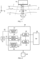
- a fluid conduit 1 has a longitudinal axis 2 which may be referred to as the z-axis and conveys a fluid 3 therethrough with a dominant flow direction 4 generally along the z-axis.
- the fluid conduit 1 may be a vessel in the human or animal circulatory system.
- An ultrasound transducer 10 is positioned to direct ultrasonic excitation energy along a beam axis 11 which may be transverse to the fluid conduit longitudinal axis 2, and may be orthogonal to the fluid conduit longitudinal axis 2 as shown in the example of figure 1 , i.e. the beam axis 11 is on the y-axis as shown, the x-axis being into the plane of the drawing.
- the transducer preferably comprises an array of transducer elements which may extend laterally to provide a wide excitation beam 12 as shown in figure 1 , where the lateral extent of the beam is along the conduit z-axis.
- the transducer 10 may be orientated to provide a lateral extent of the beam across the width of the fluid conduit 1, e.g. the beam width dimension is aligned with the x-axis or the y-axis of the fluid conduit.
- the ultrasound transducer 10 generates an excitation beam 12 comprising excitation signals configured to sample a longitudinal position or extent 13 of the conduit 1 along the z-axis and a lateral extent along the x-axis.
- the longitudinal extent 13 along the z-axis may effectively be considered as the beam width.
- the transducer 10 receives response signals, from which are generated a succession of image frames. At least a part of each image frame represents a volume element 15.
- the volume element 15 represents a finite segment of the conduit along the z-axis, and may represent a portion of the conduit in x- and y-space (orthogonal to the dominant flow axis) or may represent a full slice through the conduit, i.e. the full conduit width in one or both of x and y.
- speckle decorrelation is performed on volume elements that are a full slice through the conduit diameter and the stated finite segment of the conduit along the z-axis (which may correspond to a beam width), and variation in fluid velocity across the conduit diameter is not considered.
- Each image frame provides a spatial map of, or data set relating to, ultrasound-scattering objects in the flow and correlation of successive image frames enables the velocity of selected objects passing through the volume element 15 to be determined.
- the objects may, for example, be red blood cells, white blood cells or platelets in blood flow through an artery in the human or animal circulatory system.
- the objects may, for example, be microbubble contrast agents within the blood flow. More generally, the objects may be any objects such as single particles or clumps of particles capable of being distinguished in the ultrasound images from received ultrasound echo signals. In a general aspect, all of these objects may be described as giving speckles or speckle patterns.
- identifiable objects in the first image of the volume element 15 are identified in a successive, e.g. second, image of the volume element to see how far the objects have travelled using an autocorrelation method, e.g. where the data from the volume element is windowed longitudinally along the z-axis and successive overlapping windows along the z-axis (z 1 , z 2 , z 3 etc) are compared with the first window (z 0 ) to find a z position of maximum correlation.
- the autocorrelation method may be applied to groups of objects.
- a decorrelation-based fluid velocity measurement or fluid velocity profile measurement is made of a velocity component in the fluid flow direction using an ultrasound beam which is preferably directed with its beam axis transverse to the fluid flow direction.
- the received echo signals decorrelate with time at a rate that is a function of the particle flow velocity.
- Two images or data sets, separated by a short time interval, are taken and the correlation between the patterns of scatterers in the first image or data set and in the second image or data set is calculated. If the fluid is stationary, the correlation between the two images or data sets will be high, e.g. at or near 1.0. If the fluid is moving slowly, some of the particles (i.e.
- the expression 'image' or 'data set' is used in the present context to refer to any data set that is representative of the spatial locations / spatial distribution of speckle pattern corresponding to the particles / scatterers.
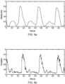
- the extent of decorrelation is found to be approximately linear with particle velocity and therefore with fluid velocity over a significant range 31 of correlation coefficient values, reaching a minimum 32 at some point.
- a decorrelation coefficient (1 - (correlation coefficient)) therefore proves to provide a good measure of, or proxy for, fluid velocity, provided that the system is confined to operation within the linear range 31.
- this correlation coefficient has been found to approximate a (half) Gaussian profile as seen in figure 3a , where the correlation coefficient still proves to provide a good measure of, or proxy for, fluid velocity, provided that the system is confined to operate within the more linear portions of the Gaussian profile, e.g. between approximately 0.9 and 0.2.
- the horizontal axis represents frame number, which is proportional to time and therefore particle velocity.
- the decorrelation flow velocity may be measured for one or more volume elements 15 to obtain a velocity measurement at a specific lateral (x and/or y) position as shown in figure 1 , or a flow velocity profile across x and/or y, or an averaged flow velocity across all x and/or y positions in the fluid conduit 1.
- the z-position of the volume element is selected to correspond to the z-position at which the conduit diameter or conduit area is being measured.
- Plotting the correlation coefficient also enables accurate determination of conduit diameter D by reference to the inflexion points 41, 42 of the correlation coefficient as a function of ultrasound reflection depth.
- a suitable edge detection algorithm may be used, e.g. based on second order gradient of the velocity profile. This could be used in conjunction with the other techniques for determining conduit diameter as described herein.
- a speckle decorrelation method used in this context may offer an advantage in that it can use a smaller spatial window (i.e. in the x, y and/or z-dimension of volume element 15) and can perform the correlation over successive frames, whereas particle imaging velocimetry techniques perform correlations over space, thereby requiring a larger effective volume element 15 extending in the z-direction ( figure 1 ).
- the particle imaging velocimetry technique generally requires capturing images of a volume element at a first time and a second time, dividing the volume of the second time image into multiple windows along the flow, or z-dimension, calculating an autocorrelation value of each window with the original volume, and finding the best match.
- the decorrelation technique can be implemented by observing a pattern of scatterers along a line (e.g. a volume element 15 that is small in z - e.g. only a beam width), whereas UIV requires a volume element 15 that provides a large spatial map of particles.
- the speckle decorrelation technique may therefore potentially be performed on lower cost, slower frame rate machines, e.g. because only one part of the array may be being fired each time. This could substantially increase clinical utility.
- the speckle decorrelation flow velocity measurement technique may also be more easily implemented to generate a fluid velocity profile across the vessel cross-section.
- the speckle decorrelation technique may also be less demanding in terms of the number of scans per second required to measure the flow, and hence in the cost and availability of the equipment required. Potentially, the method could be reduced to imaging a single line across the fluid conduit.
- the speckle decorrelation method may also be computationally less intensive in providing a direct measure of, or proxy for, fluid velocity by way of the decorrelation coefficient. This can potentially be obtained from fewer correlation operations than the autocorrelation techniques of WO 2017/163030 , which may require multiple windows within the volume elements 15 at multiple z-positions to be compared to find the maximum correlation value which corresponds to the distance travelled by the particles.
- the speckle decorrelation technique may require only two frames to be compared to obtain a single measure of decorrelation.
- n dl dDdU
- the fluid flowing in the conduit 1 is subject to pressure waves such as those caused by the heart pumping action, arterial elasticity and arterial topology as discussed earlier.
- the expression "as a function of time” is intended to encompass any changes determined by successive measurements of the relevant property at known time intervals such as unit time intervals (e.g.
- D and U are determined periodically according to the frame rate of the ultrasound transducer 10.
- dU/dt and dInD/dt may be used to determine wave speed or velocity.
- the change in fluid velocity within the volume element 15 is determined by measuring the fluid velocity at two or more successive times using the speckle decorrelation technique.
- the change in the logarithmic function of D may be determined by measuring the diameter from the ultrasound response signals at the same two or more successive times.
- Wave velocity c can then be determined by direct computation of the ratio of these two changes.
- the rate of change of fluid velocity, dU/dt may be determined for a sample period and the rate of change of the logarithmic function of conduit diameter, dInD/dt, may be determined for a corresponding, but not necessarily identical, sample period.
- the sample periods are preferably coextensive or overlapping or contiguous, but in any event are sufficiently close in time that measured changes in fluid velocity are correlated in time with measured changes in conduit diameter.
- the fluid velocity may be expressed as an average fluid velocity for the volume element 15.
- the volume element can comprise a full cross-section of the conduit diameter and the average fluid velocity can therefore be the mean velocity across the conduit diameter.
- the ultrasound response signals used to derive both fluid velocity and conduit diameter may comprise M-mode or B-mode data.
- the M-mode or B-mode data may comprise RF data from which M-mode or B-mode images may be derived, and the fluid velocity and conduit diameter may be determined directly from the RF data.
- the B-mode image data may comprise B-mode images.
- the ultrasound response signals used to derive both fluid velocity and conduit diameter may be obtained as responses to common ultrasound excitation signals.
- the ultrasound response signals used to derive both fluid velocity and conduit diameter may comprise B-mode data.
- the conduit diameter may be obtained with fewer transducer elements than required for a B-mode image, even down to a single transducer element used more frequently, e.g. M-mode. This could be interleaved with the full B-mode imaging used to obtain the velocity. Use of the M-mode could give a more accurate measure of the diameter as a function of time.
- the fluid velocity and conduit diameters may be determined at multiple times during each cardiac cycle.
- the determination of wave velocity may then be determined at multiple times during each cardiac cycle and / or the wave velocity may be determined only at selected times during each cardiac cycle.
- the wave velocity may be determined at a point in the cardiac cycle when forward waves dominate at the longitudinal position 13.
- a measure of the fluid conduit wall elasticity, at the longitudinal position 13 of the volume element 15, may be made.
- the wave velocity may be computed according to a slightly different methodology.
- the ultrasound data used to determine the conduit diameter D, as a function of time, at the longitudinal position 13 of the conduit 1 may be used to calculate a cross-sectional area A of the conduit as a function of time.
- the ultrasound measurements used to determine fluid velocity as a function of time, in the volume element 15 at the longitudinal position 13 of the conduit 1, may be used to calculate a total flow rate Q through the conduit as a function of time.
- the expression "as a function of time” is intended to encompass any changes determined by successive measurements of the relevant property (e.g.
- Q or A at known time intervals such as unit time intervals or variable time intervals, or at times when two different properties being measured can be correlated to a common point in time or time interval, as well as an instantaneous measurement of the first time derivative of that property.
- Q and A are determined periodically according to the frame rate of the ultrasound transducer 10.
- the measurements Q and A can be determined from velocity measurements U and diameter measurements D by assuming radial symmetry. Alternatively, with some more recent 3D ultrasound systems, it may be possible to obtain Q and A directly.
- Change in flow rate through the conduit may be based on successive fluid velocity measurements and conduit diameter measurements.
- Change in cross-sectional area of the conduit may be based on successive conduit diameter measurements.
- wave speed can be determined from a function of (i) the change in fluid velocity at the longitudinal position as a function of time and (ii) the change in the conduit diameter as a function of time, or wave speed can be determined from a ratio of the change in flow rate at the longitudinal position as a function of time and the change in conduit cross-sectional area as a function of time. It will be understood that in this context, a measure of the change in cross-sectional area in a conduit having a circular cross-section can readily be obtained from the measure of change in cross-sectional diameter.
- a measure of wave intensity can also be calculated from the ultrasound measurements as described above, and in particular from the determined conduit diameter and fluid velocity.
- a measure of wave energy, I can also be determined by integrating the wave intensity n dl over a period of time.
- the period of time may be from the start of a wave to the end of a wave and / or over a predetermined portion of a cardiac cycle. Determining wave energy I may be useful for long lasting waves of low intensity.
- the cross-sectional properties may include properties such as wall stiffness, wall thickness, vessel cross-sectional area, branching, bifurcation, pathological alteration of wall properties, etc.
- the longitudinal extent 13 of the volume element 15 may be of any size that provides sufficient spatial resolution for determination of the fluid velocity and conduit diameter or conduit cross-sectional area in order to achieve a determination of wave speed or wave intensity at a requisite spatial resolution.
- the wavelength of pulses affecting the fluid velocity can be quite long (e.g. of the order of more than a metre) and so the longitudinal extent 13 of the volume element 15 can be of the order of centimetres, provided that the scatterer movement can be resolved for the speckle decorrelation.
- the transducer head 10 may alternatively be directed such that the beam axis 11 is oblique to the fluid flow axis (z-axis), as long as it is capable of resolving speckle decorrelation based on movement along the z-axis and, if required from the same beam, determining conduit diameter or conduit cross-sectional area.
- the transducer head 10 could be positioned coaxial with the fluid flow axis (z-axis) at a position outside the body, as long as it is capable of resolving speckle decorrelation based on movement along that axis and, if required from the same beam, determining conduit diameter or conduit cross-sectional area at the appropriate z-position.
- the ultrasound transducer 10 can select an imaging depth that selects volume element 15 as viewed from along the z axis, or oblique to the z-axis.
- the volume element 15 represents a finite segment of the conduit along the z-axis, and may represent a portion of the conduit in x- and y-space or may represent a full slice through the conduit, i.e. the full conduit width in one or both of x and y.
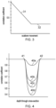
- Ultrasound transducer 10 is coupled to an ultrasound system module 20.
- An excitation module 21 or driver provides signals 22 to the transducer 10 to generate ultrasound excitation signals for insonification of the fluid conduit 1, particularly adapted to generate response signals from a selected volume element 15 at a longitudinal position 13 of the fluid conduit 1 as seen in figure 1 .
- Response signals 23 from the transducer 10 are passed to a speckle decorrelation analysis module 24 and to a geometric structure analysis module 25.
- the speckle decorrelation analysis module 24 is configured to determine a succession of fluid velocity measurements, i.e. to determine fluid velocity as a function of time, using speckle decorrelation techniques as described above.
- the speckle decorrelation analysis module 24 may also or instead be configured to calculate the total flow rate Q through the conduit as a function of time, also as discussed above.
- the geometric structure analysis module 25 is configured to determine a succession of conduit diameter measurements, i.e. to determine conduit diameter as a function of time, derived from ultrasound response signals from the conduit walls, using techniques as described above.
- the geometric structure analysis module 25 may also be configured to determine a succession of cross-sectional area measurements of the conduit from the successive diameter measurements.
- the measurements of fluid velocity as a function of time and conduit diameter as a function of time are passed to wave velocity analysis module 26 and / or wave intensity analysis module 27.
- Wave velocity analysis module 26 is configured to determine wave velocity either (i) from a ratio of the change in fluid velocity and the corresponding change in logarithmic function of conduit diameter, or (ii) from a ratio of the change in flow rate and the change in conduit cross-sectional area, at the longitudinal position 13 of the conduit, using techniques as described above.
- Wave intensity analysis module 27 is configured to determine wave intensity as a function of change in conduit diameter and corresponding change in fluid velocity, using techniques as described above.
- the various modules described above may comprise any hardware, firmware or software module or modules or combination thereof suitably configured to carry out the operations described.
- the functionalities may be kept separate or combined within one or more modules, e.g. including being implemented by a suitably programmed generic computer system.
- Ultrafast ultrasound imaging systems have recently been developed for medical applications. They beam-form and acquire data from all transducer elements in parallel instead of line by line, giving a frame rate up to two orders of magnitude higher than conventional scanners. The technique is likely to form the basis of the next generation of clinical scanners. For our purposes, the massively increased frame rate enables more accurate tracking of the rapid changes in flow and diameter that occur in arteries, and it also reduces signal-to-noise ratios by allowing averaging of repeat measurements even while meeting the stringent temporal resolution requirements. These ultrafast ultrasound imaging systems can optionally be used to perform speckle decorrelation techniques as described above.
- the ultrasound system module 20 of figure 2 may be further adapted to include a real-time graphical user interface 28 that shows a current B-mode image and a preliminary estimate of velocity from speckle decorrelation flow velocimetry, allowing a user to select a region for analysis. Furthermore, more complex algorithms to assess correlation by, for example, allowing for phase changes in the ultrasound beam or working in the frequency domain or adjusting for depth-wise variation in sensitivity, may be advantageous.
- the system module 20 may further include a semi-automated echo tracking method for monitoring arterial diameter.
- the position of the luminal surface of upper and lower conduit walls may first be marked manually, e.g. using interface 28.
- a cross correlation of the RF signals may then be used to track their position and hence obtain changes in conduit diameter D.
- Imaging and speckle decorrelation variables such as plane wave steering angles and speckle decorrelation window sizes may be optimised for accuracy and precision.
- RF data filtering may be incorporated to optimise the ultrasound signals for speckle decorrelation velocity measurements.
- speckle decorrelation measurement does not inherently provide a direction of fluid velocity. However, where required, the fluid flow direction in many or most instances will be deducible or detectable from other sensed parameters, e.g. by the time variance of the measured fluid velocity as it passes through zero and knowledge of the cardiac cycle.
- a recently-described factor [27] that corrects PWV for effects of wave reflections may be incorporated into the control software of the system module 20.
- Wave velocity and/or wave intensity analysis modules 26, 27 may be provided as separate apparatus, e.g. for off-line processing and calculation of wave speed, intensity and reflection from data captured to the database 29.
- the system 20 may be used to detect circulatory abnormalities in humans and animals by monitoring changes in wave intensities, which are altered in heart failure patients, using the non-invasive techniques described.
- vasodilator nitric oxide changes the height of the dichrotic notch (a point of inflection between the systolic and diastolic peaks) in the pressure or volume wave.
- Substances which stimulate NO release such as acetylcholine (ACh)
- ACh acetylcholine
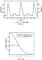
- Substances like L-NAME that inhibit NO production raise the height of the dichrotic notch, relative to the overall amplitude of the wave. It has been shown that these changes are quite specific to NO (and the related nitrovasodilators); they do not reflect general influences of vasoactive agents on peripheral tone, blood pressure or heart rate. The effect may be due to altered wave reflections as illustrated in figure 4 .
- the system 20 may be deployed to determine the effects of NO on wave reflections.
- the system 20 may be usable to detect heart failure, age-related arterial stiffening and NO-dependent wave reflection in pre-clinical models.
- Wave Intensity Analysis conceptualises waves as being built up of infinitesimal wavefronts that travel forward or backwards with known intensities at specific times. The breakdown of the pulse wave in this way makes it much easier to relate its features to real cardiac and vascular properties.
- WIA may be used in procedures that evaluate the functional significance of coronary stenoses, and hence determine whether intervention is required. It identifies naturally wave-free periods during the cardiac cycle. At such points, the ratio of pressure upstream and downstream of a stenosis can be used to assess the resistance it causes. In a conventional procedure, such periods are not identified and waves may have to be eliminated by administering vasodilating drugs, which is time consuming, expensive, unpleasant for the patient and not feasible in some patient groups.
- the techniques described herein may provide a non-invasive method without requiring catheterization.
- the system may be used for investigating Heart Failure.
- Curtiss et al [1] compared normal subjects and patients with compensated systolic heart failure.
- the energy in a re-reflected expansion wave (the X wave) was 80% lower in the patients.
- the augmentation index based on tonometry - a supposed measure of wave reflections that is not based on WIA - was unchanged.
- Takaya et al [37] examined patients having chronic heart failure with normal ejection fraction under exercise testing, an accepted method for predicting survival. No transthoracic echocardiography parameters correlated significantly with any exercise parameter, but the intensity of the forward expansion wave (W2) correlated significantly with all exercise parameters, implying that this simple non-invasive measure will better predict outcome.
- W2 forward expansion wave
- Vriz et al [38] conducted a longitudinal study of patients with heart failure and reduced ejection fraction, comparing wave parameters with echocardiographic indices of left ventricular function. Average follow-up was >3 yr. On stepwise backward multiple regression, only a wave parameter - the intensity of W2 - was an independent predictor of outcome.
- Li and Guo [39] assessed the value of WIA in differentiating non-obstructive hypertrophic cardiomyopathy (NOHCM) from left ventricular hypertrophy secondary to hypertension (LVHSH). They examined the forward going compression (W1) and expansion (W2) waves and an area of negative wave intensity (NA) resulting from peripheral reflections. W2 was lower in NOHCM than in LVHSH and in normal subjects.
- NOHCM non-obstructive hypertrophic cardiomyopathy
- Endothelial dysfunction characterised principally by a reduction in NO bioavailability - is a strong risk factor for cardiovascular disease but rarely assessed. That is unfortunate because a number of lifestyle changes have been shown to improve endothelial function. Several pharmacological approaches are also under investigation [43, 44]. It is likely to reflect the technical challenge of measuring such dysfunction.
- Figure 5 illustrates blood flow velocity measurements taken using the speckle decorrelation techniques as described herein, compared with existing Doppler techniques.
- Figure 5a shows blood flow velocity measured invasively by the "gold standard" Doppler method (top) and figure 5b shows the blood flow velocity as measured by the speckle decorrelation technique. Both measurements were taken in the abdominal aorta of the same anaesthetised rabbit. Data are shown for three heart beats. Measurements were made at different times since the Doppler system and the B-mode system interfere. A similar pattern is seen in the two panels for the main peak.
- the errors occur after the part of cardiac cycle that is of interest for diagnosing heart failure - the maximum acceleration and deceleration of flow which correspond to the peaks of the compression and expansion waves.
- Noise in the speckle decorrelation data of figure 5b can be eliminated by filtering and averaging. Contrast agents were not used.
- Figure 6 illustrates blood flow velocity measurements taken using the speckle decorrelation techniques as described herein, compared with ultrasound image velocimetry (UIV), showing a close comparison.
- the data for the speckle decorrelation results were acquired with a transducer head aligned with its beam axis 11 orthogonal to the fluid conduit longitudinal axis 2 (z-axis), and with the beam width dimension or lateral extent of the beam along the z-axis.
- the methods of determining wave speed and / or determining wave intensity generally have application in any non-rigid fluid conduit system, particularly within a system exhibiting elastic behaviour in the walls in at least part of the system.
- the expression 'conduit' encompasses pipes and tubes which may have varying diameters and cross-sectional profiles, which may be branching and which may have chambers connected thereto.
- the techniques described could be applied in any elastic walled fluid conduit which has sufficient transparency to ultrasound to enable a quantitative measurement of decorrelation of objects in successive ultrasound frames of a flow of fluid within the conduit.
- the techniques could generally be applicable to a system where compression / decompression waves may arise within the fluid conduit, e.g. from the operation of valves within the system.
- the equations used as described above, to determine wave speed, wave intensity, and / or wave energy can be modified for greater accuracy to take into account other measurable properties of the system such as viscosity of the fluid medium (e.g. blood), viscoelasticity of the conduit walls and other non-linear effects.
- this may be achieved by making additional measurements of D or U (or equivalently additional measurements of A or Q) at a second site along the conduit.
- the equations used to determine wave speed could be modified to take account of reflections, e.g. using a correction factor as derived by P Segers et al [27] .
- Wave intensity analysis techniques such as those used in this disclosure can be improved by subtracting "windkessel” effects, i.e. subtracting the pressure that is caused by the elastic vessels being pumped full of blood, and not by waves [56].
Landscapes
- Health & Medical Sciences (AREA)
- Life Sciences & Earth Sciences (AREA)
- Engineering & Computer Science (AREA)
- Physics & Mathematics (AREA)
- Public Health (AREA)
- Medical Informatics (AREA)
- General Health & Medical Sciences (AREA)
- Pathology (AREA)
- Biomedical Technology (AREA)
- Veterinary Medicine (AREA)
- Radiology & Medical Imaging (AREA)
- Heart & Thoracic Surgery (AREA)
- Nuclear Medicine, Radiotherapy & Molecular Imaging (AREA)
- Molecular Biology (AREA)
- Surgery (AREA)
- Animal Behavior & Ethology (AREA)
- Biophysics (AREA)
- Radar, Positioning & Navigation (AREA)
- Remote Sensing (AREA)
- General Physics & Mathematics (AREA)
- Acoustics & Sound (AREA)
- Hematology (AREA)
- Computer Networks & Wireless Communication (AREA)
- Computer Vision & Pattern Recognition (AREA)
- Primary Health Care (AREA)
- Physiology (AREA)
- Data Mining & Analysis (AREA)
- Databases & Information Systems (AREA)
- Epidemiology (AREA)
- Cardiology (AREA)
- Multimedia (AREA)
- Aviation & Aerospace Engineering (AREA)
- Vascular Medicine (AREA)
- Electromagnetism (AREA)
- Fluid Mechanics (AREA)
- Ultra Sonic Daignosis Equipment (AREA)
Claims (26)
- Procédé de détermination d'une mesure de vitesse d'onde dans un fluide (3) s'écoulant (4) à travers un conduit de fluide (1), le procédé comprenant :l'utilisation de mesures par ultrasons (12) destinées à déterminer le diamètre de conduit (D) ou la section transversale de conduit (A), en fonction du temps, au niveau d'une position longitudinale (13) du conduit ;l'utilisation de mesures par ultrasons destinées à déterminer une mesure de vitesse de fluide, en fonction du temps, dans un élément de volume au niveau de ladite position longitudinale du conduit, les mesures par ultrasons destinées à déterminer la mesure de vitesse de fluide étant réalisées par décorrélation d'objets diffusants à l'intérieur de l'écoulement de fluide dans des trames successives échantillonnant l'élément de volume, dans lequel la vitesse de fluide est déterminée en utilisant une vélocimétrie par décorrélation de speckle ;la détermination de la mesure de vitesse d'onde à partir d'une fonction (i) du changement de la mesure de vitesse de fluide au niveau de la position longitudinale en fonction du temps et (ii) du changement du diamètre de conduit (D) ou de la section transversale de conduit (A), en fonction du temps.
- Procédé selon la revendication 1 dans lequel la vitesse d'onde est déterminée à partir(i) d'un rapport entre le changement de la mesure de vitesse de fluide au niveau de la position longitudinale en fonction du temps et le changement d'une fonction logarithmique du diamètre de conduit en fonction du temps, ou(ii) d'un rapport entre un changement de la mesure de vitesse de fluide au niveau de la position longitudinale dans un intervalle de temps et un changement correspondant d'une fonction logarithmique du diamètre de conduit dans le même intervalle de temps.
- Procédé selon la revendication 1 dans lequel la vitesse d'onde est déterminée à partir du changement de la mesure de vitesse de fluide au niveau de la position longitudinale dans un intervalle de temps et un changement correspondant du diamètre de conduit dans le même intervalle de temps.
- Procédé selon la revendication 1 dans lequel la mesure de vitesse de fluide comprend un coefficient de décorrélation pour des objets diffusants dans lesdites trames successives et dans lequel la vitesse d'onde, c', est déterminée selon l'équation c' = 0,5(dU' / dlnD), où dU' est un changement du coefficient de décorrélation U' en fonction du temps et dlnD est un changement du logarithme népérien de D en fonction du temps, et c' est une mesure mise à l'échelle de la vitesse d'onde réelle.
- Procédé selon la revendication 1 dans lequel la mesure de vitesse de fluide comprend un coefficient de décorrélation pour des objets diffusants dans lesdites trames successives et dans lequel la vitesse d'onde, c', est déterminée selon l'équation c' = AdU'/dA ou c' = dU'/dlnA, où A est la section transversale, dA est le changement de la section transversale en fonction du temps, dU' est un changement du coefficient de décorrélation U' en fonction du temps et dlnA est un changement du logarithme népérien de A en fonction du temps et c' est une mesure mise à l'échelle de la vitesse d'onde réelle.
- Procédé de détermination d'une mesure de vitesse d'onde dans un fluide (3) s'écoulant (4) à travers un conduit de fluide (1), le procédé comprenant :l'utilisation de mesures par ultrasons (12) destinées à déterminer le diamètre de conduit (D), en fonction du temps, au niveau d'une position longitudinale (13) du conduit (1) ;l'utilisation de mesures par ultrasons destinées à déterminer une mesure de vitesse de fluide, en fonction du temps, dans un élément de volume (15) au niveau de ladite position longitudinale (13) du conduit, les mesures par ultrasons destinées à déterminer la mesure de vitesse de fluide étant réalisées par décorrélation d'objets diffusants à l'intérieur de l'écoulement de fluide dans des trames successives échantillonnant l'élément de volume, dans lesquelles la vitesse de fluide est déterminée en utilisant une vélocimétrie par décorrélation de speckle ;la détermination d'un changement de débit à travers le conduit (1) sur la base des mesures de vitesse de fluide et des mesures de diamètre de conduit ;la détermination d'un changement de section transversale du conduit sur la base des mesures de diamètre de conduit ; etla détermination de la mesure de vitesse d'onde à partir d'un rapport entre le changement de débit au niveau de la position longitudinale en fonction du temps et le changement de section transversale de conduit en fonction du temps.
- Procédé selon la revendication 6 dans lequel la vitesse d'onde, c, est déterminée selon l'équation c = dQ / dA, où dQ est un changement du débit d'écoulement et dA est un changement de la section transversale du conduit.
- Procédé selon la revendication 1 ou la revendication 6 comportant en outre la détermination d'une mesure d'élasticité ou de distensibilité de paroi de conduit de fluide au niveau de l'élément de volume, à partir de la vitesse d'onde.
- Procédé de détermination d'une mesure d'intensité d'onde dans un conduit (1) de fluide (3), le procédé comprenant :l'utilisation de mesures par ultrasons (12) destinées à déterminer le diamètre de conduit (D), en fonction du temps, au niveau d'une position longitudinale (13) du conduit ;l'utilisation de mesures par ultrasons destinées à déterminer une mesure de vitesse de fluide, en fonction du temps, dans un élément de volume au niveau de ladite position longitudinale du conduit, les mesures par ultrasons destinées à déterminer la mesure de vitesse de fluide étant réalisées par décorrélation d'objets diffusants à l'intérieur de l'écoulement de fluide dans des trames successives échantillonnant l'élément de volume, dans lequel la vitesse de fluide est déterminée en utilisant une vélocimétrie par décorrélation de speckle ;la détermination d'une mesure d'intensité d'onde en fonction d'un changement du diamètre de conduit (D) déterminé et d'un changement correspondant de la mesure de vitesse de fluide.
- Procédé selon la revendication 1, la revendication 6 ou la revendication 9 dans lequel la mesure de vitesse de fluide comprend un coefficient de décorrélation pour des objets diffusants dans lesdites trames successives.
- Procédé selon la revendication 1, la revendication 6 ou la revendication 9 dans lequel les mesures par ultrasons destinées à déterminer une mesure de vitesse de fluide comprennent une série d'images en mode M ou en mode B ou de données RF en mode M ou en mode B, et la détermination de la mesure de vitesse de fluide comprend la mesure d'un coefficient de corrélation pour les objets diffusants dans des trames successives des images en mode M ou en mode B ou des données RF en mode M ou en mode B.
- Procédé selon la revendication 10 dans lequel les mesures par ultrasons destinées à déterminer un diamètre de conduit et un coefficient de décorrélation sont dérivées d'une tête de transducteur à ultrasons commune (10).
- Procédé selon la revendication 12 dans lequel la tête de transducteur à ultrasons commune (10) est dirigée (11) de sorte que l'axe de faisceau soit orthogonal ou oblique par rapport à l'axe d'écoulement de fluide (4) du conduit d'écoulement de fluide (1).
- Procédé selon la revendication 12 dans lequel les mesures par ultrasons destinées à déterminer un diamètre de conduit (D) ou une section transversale de conduit et la mesure de vitesse de fluide sont dérivées de signaux d'excitation et de réponse ultrasonores communs.
- Procédé selon la revendication 9 comportant en outre la détermination d'une vitesse d'onde dans le conduit de fluide (1), et dans lequel la mesure d'intensité d'onde est déterminée en fonction du diamètre de conduit (D) déterminé, de la mesure de vitesse de fluide déterminée et de la vitesse d'onde déterminée.
- Procédé selon la revendication 9 dans lequel la mesure de vitesse de fluide comprend un coefficient de décorrélation pour des objets diffusants dans lesdites trames successives et dans lequel la mesure d'intensité d'onde est déterminée selon l'équation :

- Procédé selon la revendication 9 dans lequel la mesure d'intensité d'onde est déterminée selon l'équation ndl = dDdU, où ndl est l'intensité d'onde déterminée à partir de mesures non invasives ; dD est le changement de diamètre de conduit ; et dU est le changement de la mesure de vitesse de fluide.
- Procédé selon la revendication 16 ou 17 comportant en outre la détermination d'une énergie d'onde en intégrant l'intensité d'onde sur une période de temps.
- Procédé selon la revendication 15 dans lequel la vitesse d'onde est déterminée en fonction d'un rapport du changement de la mesure de vitesse de fluide au niveau de la position longitudinale en fonction du temps et du changement d'une fonction logarithmique du diamètre de conduit en fonction du temps.
- Procédé selon la revendication 19 dans lequel une mesure de vitesse d'onde, c', est déterminée selon l'équation c' = 0,5(dU' / dlnD), où dU' est un changement du coefficient de décorrélation U' en fonction du temps et dlnD est un changement du logarithme népérien de D en fonction du temps.
- Procédé selon la revendication 1, la revendication 6 ou la revendication 9 dans lequel le conduit de fluide (1) comprend une partie du système circulatoire humain ou animal.
- Procédé selon la revendication 21 comportant en outre la répétition des mesures par ultrasons et la détermination d'une intensité d'onde à de multiples reprises pendant un cycle cardiaque et la corrélation de la mesure d'intensité d'onde avec le temps dans le cycle cardiaque.
- Procédé selon la revendication 20 dans lequel les objets suivis comprennent des globules rouges, des globules blancs, des plaquettes ou des entités de produit de contraste.
- Procédé selon la revendication 9 comportant en outre la détermination d'une mesure de propriétés de section transversale de conduit de fluide en amont et/ou en aval de l'élément de volume (15) échantillonné à partir de l'intensité d'onde.
- Procédé selon la revendication 21 comportant en outre la détermination d'un profil de débit cardiaque à partir de l'intensité d'onde.
- Appareil (10, 20) pour déterminer une mesure de vitesse d'onde ou d'intensité d'onde dans un conduit de fluide, comprenant :
un module d'analyse (24, 25, 26, 27) configuré pour réaliser les étapes selon l'une quelconque des revendications 1 à 25.
Applications Claiming Priority (2)
| Application Number | Priority Date | Filing Date | Title |
|---|---|---|---|
| GB1800481.2A GB2570131A (en) | 2018-01-11 | 2018-01-11 | Fluid flow analysis |
| PCT/GB2019/050074 WO2019138241A1 (fr) | 2018-01-11 | 2019-01-11 | Analyse d'écoulement de fluide |
Publications (2)
| Publication Number | Publication Date |
|---|---|
| EP3737293A1 EP3737293A1 (fr) | 2020-11-18 |
| EP3737293B1 true EP3737293B1 (fr) | 2025-03-05 |
Family
ID=61256259
Family Applications (1)
| Application Number | Title | Priority Date | Filing Date |
|---|---|---|---|
| EP19701900.3A Active EP3737293B1 (fr) | 2018-01-11 | 2019-01-11 | Analyse d'écoulement de fluide |
Country Status (5)
| Country | Link |
|---|---|
| US (1) | US12144674B2 (fr) |
| EP (1) | EP3737293B1 (fr) |
| CN (1) | CN111801053A (fr) |
| GB (1) | GB2570131A (fr) |
| WO (1) | WO2019138241A1 (fr) |
Families Citing this family (5)
| Publication number | Priority date | Publication date | Assignee | Title |
|---|---|---|---|---|
| KR102482475B1 (ko) * | 2020-09-24 | 2022-12-28 | 포항공과대학교 산학협력단 | 적응적 하이브리드 유동 측정 방법 및 이를 수행하는 장치 |
| US20230414123A1 (en) * | 2020-11-17 | 2023-12-28 | Case Western Reserve University | System and method for measuring blood flow velocity on a microfluidic chip |
| EP4008267A1 (fr) * | 2020-12-01 | 2022-06-08 | Koninklijke Philips N.V. | Détermination de la vélocité du sang |
| US12462371B2 (en) * | 2021-05-28 | 2025-11-04 | Institut National De La Sante Et De La Recherche Medicale (Inserm)—Raison Sociale Obsolete | Computer-implemented method and apparatus for characterizing a flexible tube |
| JP7746547B2 (ja) * | 2021-09-25 | 2025-09-30 | メディカル・エーアイ・カンパニー・リミテッド | ディープラーニングに基づいて連続的な身体状態を計測する方法、コンピュータプログラム及び装置 |
Citations (1)
| Publication number | Priority date | Publication date | Assignee | Title |
|---|---|---|---|---|
| EP1122556A2 (fr) * | 2000-01-31 | 2001-08-08 | General Electric Company | Imagerie harmonique améliorée générée dans les tissus employant l'excitation codée |
Family Cites Families (16)
| Publication number | Priority date | Publication date | Assignee | Title |
|---|---|---|---|---|
| FR1539652A (fr) * | 1967-04-07 | 1968-09-20 | Comp Generale Electricite | Débitmètre enregistreur pour vaisseau sanguin |
| US4733669A (en) * | 1985-05-24 | 1988-03-29 | Cardiometrics, Inc. | Blood flow measurement catheter |
| EP0321717B1 (fr) * | 1987-11-30 | 1995-07-05 | Aloka Co. Ltd. | Procédé et dispositif de mesure de la vitesse du fluide au moyen d'ondes ultrasonores |
| FI94909C (fi) * | 1994-04-19 | 1995-11-10 | Valtion Teknillinen | Akustinen virtausmittausmenetelmä ja sitä soveltava laite |
| EP0839497A1 (fr) * | 1996-11-01 | 1998-05-06 | EndoSonics Corporation | Procédé pour mesurer le débit volumétrique et son profil de vitesse dans un lumen ou dans une cavité d'un corps |
| JP3857788B2 (ja) * | 1997-09-01 | 2006-12-13 | テルモ株式会社 | 循環器情報計測システム |
| US6535835B1 (en) * | 2000-01-31 | 2003-03-18 | Ge Medical Systems Global Technology Company, Llc | Angle independent ultrasound volume flow measurement |
| EP1123687A3 (fr) * | 2000-02-10 | 2004-02-04 | Aloka Co., Ltd. | Appareil diagnostique à ultrasons |
| US20070167809A1 (en) * | 2002-07-22 | 2007-07-19 | Ep Medsystems, Inc. | Method and System For Estimating Cardiac Ejection Volume And Placing Pacemaker Electrodes Using Speckle Tracking |
| EP1703261A4 (fr) * | 2003-12-26 | 2007-07-04 | Tokyo Electric Power Co | Debitmetre ultrasonore, coin pour debitmetre ultrasonore, procede de reglage d'unite de transmission/reception d'ultrasons, et unite de transmission/reception d'ultrasons |
| JP5158679B2 (ja) * | 2007-09-14 | 2013-03-06 | 国立大学法人岐阜大学 | 画像処理装置、画像処理プログラム、記憶媒体及び超音波診断装置 |
| JP5497821B2 (ja) * | 2012-03-16 | 2014-05-21 | 国立大学法人 東京大学 | 流体流速検出装置及びプログラム |
| CN106456118B (zh) * | 2013-11-19 | 2019-12-31 | 港大科桥有限公司 | 超声流体向量成像装置及其方法 |
| WO2015187573A1 (fr) * | 2014-06-03 | 2015-12-10 | Rush University Medical Center | Dispositif de mesure d'impédance vasculaire et procédé de détermination d'impédance |
| GB201604873D0 (en) * | 2016-03-22 | 2016-05-04 | Imp Innovations Ltd | Fluid flow analysis |
| EP3457911A1 (fr) * | 2016-05-20 | 2019-03-27 | Koninklijke Philips N.V. | Dispositifs et procédés de détermination de la vitesse des ondes de pouls sur la base des changements de diamètre du vaisseau |
-
2018
- 2018-01-11 GB GB1800481.2A patent/GB2570131A/en not_active Withdrawn
-
2019
- 2019-01-11 WO PCT/GB2019/050074 patent/WO2019138241A1/fr not_active Ceased
- 2019-01-11 EP EP19701900.3A patent/EP3737293B1/fr active Active
- 2019-01-11 US US16/961,360 patent/US12144674B2/en active Active
- 2019-01-11 CN CN201980016493.9A patent/CN111801053A/zh active Pending
Patent Citations (1)
| Publication number | Priority date | Publication date | Assignee | Title |
|---|---|---|---|---|
| EP1122556A2 (fr) * | 2000-01-31 | 2001-08-08 | General Electric Company | Imagerie harmonique améliorée générée dans les tissus employant l'excitation codée |
Also Published As
| Publication number | Publication date |
|---|---|
| EP3737293A1 (fr) | 2020-11-18 |
| WO2019138241A1 (fr) | 2019-07-18 |
| US12144674B2 (en) | 2024-11-19 |
| US20200345323A1 (en) | 2020-11-05 |
| GB201800481D0 (en) | 2018-02-28 |
| CN111801053A (zh) | 2020-10-20 |
| GB2570131A (en) | 2019-07-17 |
Similar Documents
| Publication | Publication Date | Title |
|---|---|---|
| US12232906B2 (en) | Fluid flow analysis | |
| EP3737293B1 (fr) | Analyse d'écoulement de fluide | |
| Meinders et al. | Assessment of local pulse wave velocity in arteries using 2D distension waveforms | |
| Beulen et al. | Toward noninvasive blood pressure assessment in arteries by using ultrasound | |
| Seo et al. | Noninvasive arterial blood pressure waveform monitoring using two-element ultrasound system | |
| CN100512764C (zh) | 超声诊断设备和超声诊断方法 | |
| Nagaoka et al. | Measurement of regional pulse-wave velocity using spatial compound imaging of the common carotid artery in vivo | |
| US20160095572A1 (en) | System and Method for Non-Invasive Blood Pressure Measurement | |
| WO2012021765A2 (fr) | Méthodes et appareil permettant de déterminer la vitesse de l'onde pulsatile artérielle | |
| WO2008038615A1 (fr) | dispositif ÉCHOGRAPHIQUE | |
| US11918413B2 (en) | Ultrasound probe, system and method for measuring arterial parameters using non-imaging ultrasound | |
| Park et al. | Ultrasound deep learning for monitoring of flow–vessel dynamics in murine carotid artery | |
| WO2006129545A1 (fr) | Ultrasonographe | |
| Sorensen et al. | Pulse wave velocity in the carotid artery | |
| EP2034901B1 (fr) | Détection globale et locale de l'élasticité d'un vaisseau sanguin | |
| Manoj et al. | Measurement of Local Pulse Wave Velocity: Agreement Among Various Methodologies | |
| Bazan et al. | Power spectral estimation of high-harmonics in echoes of wall resonances to improve resolution in non-invasive measurements of wall mechanical properties in rubber tube and ex-vivo artery | |
| Xu et al. | Continuous and noninvasive measurement of arterial pulse pressure and pressure waveform using an image-free ultrasound system | |
| Seo et al. | Monitoring of pulse pressure and arterial pressure waveform changes during the valsalva maneuver by a portable ultrasound system | |
| Manoj et al. | Measurement of Inter and Intra-cycle Variations in Local Pulse Wave Velocity from Forward Travelling Pulse Waves | |
| Patil et al. | A method for localized computation of Pulse Wave Velocity in carotid structure | |
| Nabeel et al. | Local evaluation of variation in pulse wave velocity over the cardiac cycle using single-element ultrasound transducer | |
| Joseph et al. | Non-invasive estimation of arterial compliance | |
| Wang et al. | Estimation of cardiac output based on PRAM algorithm and ARX model from noninvasive radial pressure wave | |
| Aristizabal et al. | Application of Guided Waves for Quantifying Elasticity and Viscoelasticity of Boundary Sensitive Organs |
Legal Events
| Date | Code | Title | Description |
|---|---|---|---|
| STAA | Information on the status of an ep patent application or granted ep patent |
Free format text: STATUS: UNKNOWN |
|
| STAA | Information on the status of an ep patent application or granted ep patent |
Free format text: STATUS: THE INTERNATIONAL PUBLICATION HAS BEEN MADE |
|
| PUAI | Public reference made under article 153(3) epc to a published international application that has entered the european phase |
Free format text: ORIGINAL CODE: 0009012 |
|
| STAA | Information on the status of an ep patent application or granted ep patent |
Free format text: STATUS: REQUEST FOR EXAMINATION WAS MADE |
|
| 17P | Request for examination filed |
Effective date: 20200807 |
|
| AK | Designated contracting states |
Kind code of ref document: A1 Designated state(s): AL AT BE BG CH CY CZ DE DK EE ES FI FR GB GR HR HU IE IS IT LI LT LU LV MC MK MT NL NO PL PT RO RS SE SI SK SM TR |
|
| AX | Request for extension of the european patent |
Extension state: BA ME |
|
| DAV | Request for validation of the european patent (deleted) | ||
| DAX | Request for extension of the european patent (deleted) | ||
| STAA | Information on the status of an ep patent application or granted ep patent |
Free format text: STATUS: EXAMINATION IS IN PROGRESS |
|
| 17Q | First examination report despatched |
Effective date: 20220509 |
|
| GRAP | Despatch of communication of intention to grant a patent |
Free format text: ORIGINAL CODE: EPIDOSNIGR1 |
|
| STAA | Information on the status of an ep patent application or granted ep patent |
Free format text: STATUS: GRANT OF PATENT IS INTENDED |
|
| INTG | Intention to grant announced |
Effective date: 20230807 |
|
| GRAJ | Information related to disapproval of communication of intention to grant by the applicant or resumption of examination proceedings by the epo deleted |
Free format text: ORIGINAL CODE: EPIDOSDIGR1 |
|
| STAA | Information on the status of an ep patent application or granted ep patent |
Free format text: STATUS: EXAMINATION IS IN PROGRESS |
|
| INTC | Intention to grant announced (deleted) | ||
| GRAP | Despatch of communication of intention to grant a patent |
Free format text: ORIGINAL CODE: EPIDOSNIGR1 |
|
| STAA | Information on the status of an ep patent application or granted ep patent |
Free format text: STATUS: GRANT OF PATENT IS INTENDED |
|
| RIC1 | Information provided on ipc code assigned before grant |
Ipc: G16H 50/30 20180101ALI20240925BHEP Ipc: A61B 8/08 20060101ALI20240925BHEP Ipc: G01S 15/89 20060101ALI20240925BHEP Ipc: A61B 8/06 20060101AFI20240925BHEP |
|
| INTG | Intention to grant announced |
Effective date: 20241008 |
|
| GRAS | Grant fee paid |
Free format text: ORIGINAL CODE: EPIDOSNIGR3 |
|
| GRAA | (expected) grant |
Free format text: ORIGINAL CODE: 0009210 |
|
| STAA | Information on the status of an ep patent application or granted ep patent |
Free format text: STATUS: THE PATENT HAS BEEN GRANTED |
|
| AK | Designated contracting states |
Kind code of ref document: B1 Designated state(s): AL AT BE BG CH CY CZ DE DK EE ES FI FR GB GR HR HU IE IS IT LI LT LU LV MC MK MT NL NO PL PT RO RS SE SI SK SM TR |
|
| P01 | Opt-out of the competence of the unified patent court (upc) registered |
Free format text: CASE NUMBER: APP_4035/2025 Effective date: 20250124 |
|
| REG | Reference to a national code |
Ref country code: GB Ref legal event code: FG4D |
|
| REG | Reference to a national code |
Ref country code: CH Ref legal event code: EP |
|
| REG | Reference to a national code |
Ref country code: DE Ref legal event code: R096 Ref document number: 602019066807 Country of ref document: DE |
|
| REG | Reference to a national code |
Ref country code: IE Ref legal event code: FG4D |
|
| PG25 | Lapsed in a contracting state [announced via postgrant information from national office to epo] |
Ref country code: RS Free format text: LAPSE BECAUSE OF FAILURE TO SUBMIT A TRANSLATION OF THE DESCRIPTION OR TO PAY THE FEE WITHIN THE PRESCRIBED TIME-LIMIT Effective date: 20250605 |
|
| PG25 | Lapsed in a contracting state [announced via postgrant information from national office to epo] |
Ref country code: FI Free format text: LAPSE BECAUSE OF FAILURE TO SUBMIT A TRANSLATION OF THE DESCRIPTION OR TO PAY THE FEE WITHIN THE PRESCRIBED TIME-LIMIT Effective date: 20250305 |
|
| REG | Reference to a national code |
Ref country code: NL Ref legal event code: MP Effective date: 20250305 |
|
| PG25 | Lapsed in a contracting state [announced via postgrant information from national office to epo] |
Ref country code: ES Free format text: LAPSE BECAUSE OF FAILURE TO SUBMIT A TRANSLATION OF THE DESCRIPTION OR TO PAY THE FEE WITHIN THE PRESCRIBED TIME-LIMIT Effective date: 20250305 |
|
| REG | Reference to a national code |
Ref country code: LT Ref legal event code: MG9D |
|
| PG25 | Lapsed in a contracting state [announced via postgrant information from national office to epo] |
Ref country code: NO Free format text: LAPSE BECAUSE OF FAILURE TO SUBMIT A TRANSLATION OF THE DESCRIPTION OR TO PAY THE FEE WITHIN THE PRESCRIBED TIME-LIMIT Effective date: 20250605 |
|
| PG25 | Lapsed in a contracting state [announced via postgrant information from national office to epo] |
Ref country code: HR Free format text: LAPSE BECAUSE OF FAILURE TO SUBMIT A TRANSLATION OF THE DESCRIPTION OR TO PAY THE FEE WITHIN THE PRESCRIBED TIME-LIMIT Effective date: 20250305 |
|
| PG25 | Lapsed in a contracting state [announced via postgrant information from national office to epo] |
Ref country code: LV Free format text: LAPSE BECAUSE OF FAILURE TO SUBMIT A TRANSLATION OF THE DESCRIPTION OR TO PAY THE FEE WITHIN THE PRESCRIBED TIME-LIMIT Effective date: 20250305 |
|
| PG25 | Lapsed in a contracting state [announced via postgrant information from national office to epo] |
Ref country code: GR Free format text: LAPSE BECAUSE OF FAILURE TO SUBMIT A TRANSLATION OF THE DESCRIPTION OR TO PAY THE FEE WITHIN THE PRESCRIBED TIME-LIMIT Effective date: 20250606 Ref country code: BG Free format text: LAPSE BECAUSE OF FAILURE TO SUBMIT A TRANSLATION OF THE DESCRIPTION OR TO PAY THE FEE WITHIN THE PRESCRIBED TIME-LIMIT Effective date: 20250305 |
|
| REG | Reference to a national code |
Ref country code: AT Ref legal event code: MK05 Ref document number: 1772148 Country of ref document: AT Kind code of ref document: T Effective date: 20250305 |
|
| PG25 | Lapsed in a contracting state [announced via postgrant information from national office to epo] |
Ref country code: NL Free format text: LAPSE BECAUSE OF FAILURE TO SUBMIT A TRANSLATION OF THE DESCRIPTION OR TO PAY THE FEE WITHIN THE PRESCRIBED TIME-LIMIT Effective date: 20250305 |
|
| PG25 | Lapsed in a contracting state [announced via postgrant information from national office to epo] |
Ref country code: SE Free format text: LAPSE BECAUSE OF FAILURE TO SUBMIT A TRANSLATION OF THE DESCRIPTION OR TO PAY THE FEE WITHIN THE PRESCRIBED TIME-LIMIT Effective date: 20250305 |
|
| PG25 | Lapsed in a contracting state [announced via postgrant information from national office to epo] |
Ref country code: SM Free format text: LAPSE BECAUSE OF FAILURE TO SUBMIT A TRANSLATION OF THE DESCRIPTION OR TO PAY THE FEE WITHIN THE PRESCRIBED TIME-LIMIT Effective date: 20250305 |
|
| PG25 | Lapsed in a contracting state [announced via postgrant information from national office to epo] |
Ref country code: PT Free format text: LAPSE BECAUSE OF FAILURE TO SUBMIT A TRANSLATION OF THE DESCRIPTION OR TO PAY THE FEE WITHIN THE PRESCRIBED TIME-LIMIT Effective date: 20250707 |
|
| PG25 | Lapsed in a contracting state [announced via postgrant information from national office to epo] |
Ref country code: PL Free format text: LAPSE BECAUSE OF FAILURE TO SUBMIT A TRANSLATION OF THE DESCRIPTION OR TO PAY THE FEE WITHIN THE PRESCRIBED TIME-LIMIT Effective date: 20250305 Ref country code: IT Free format text: LAPSE BECAUSE OF FAILURE TO SUBMIT A TRANSLATION OF THE DESCRIPTION OR TO PAY THE FEE WITHIN THE PRESCRIBED TIME-LIMIT Effective date: 20250305 |
|
| PG25 | Lapsed in a contracting state [announced via postgrant information from national office to epo] |
Ref country code: AT Free format text: LAPSE BECAUSE OF FAILURE TO SUBMIT A TRANSLATION OF THE DESCRIPTION OR TO PAY THE FEE WITHIN THE PRESCRIBED TIME-LIMIT Effective date: 20250305 |
|
| PG25 | Lapsed in a contracting state [announced via postgrant information from national office to epo] |
Ref country code: EE Free format text: LAPSE BECAUSE OF FAILURE TO SUBMIT A TRANSLATION OF THE DESCRIPTION OR TO PAY THE FEE WITHIN THE PRESCRIBED TIME-LIMIT Effective date: 20250305 Ref country code: CZ Free format text: LAPSE BECAUSE OF FAILURE TO SUBMIT A TRANSLATION OF THE DESCRIPTION OR TO PAY THE FEE WITHIN THE PRESCRIBED TIME-LIMIT Effective date: 20250305 |
|
| PG25 | Lapsed in a contracting state [announced via postgrant information from national office to epo] |
Ref country code: RO Free format text: LAPSE BECAUSE OF FAILURE TO SUBMIT A TRANSLATION OF THE DESCRIPTION OR TO PAY THE FEE WITHIN THE PRESCRIBED TIME-LIMIT Effective date: 20250305 |
|
| PG25 | Lapsed in a contracting state [announced via postgrant information from national office to epo] |
Ref country code: SK Free format text: LAPSE BECAUSE OF FAILURE TO SUBMIT A TRANSLATION OF THE DESCRIPTION OR TO PAY THE FEE WITHIN THE PRESCRIBED TIME-LIMIT Effective date: 20250305 |
|
| PG25 | Lapsed in a contracting state [announced via postgrant information from national office to epo] |
Ref country code: IS Free format text: LAPSE BECAUSE OF FAILURE TO SUBMIT A TRANSLATION OF THE DESCRIPTION OR TO PAY THE FEE WITHIN THE PRESCRIBED TIME-LIMIT Effective date: 20250705 |
|
| REG | Reference to a national code |
Ref country code: DE Ref legal event code: R097 Ref document number: 602019066807 Country of ref document: DE |
|
| PLBE | No opposition filed within time limit |
Free format text: ORIGINAL CODE: 0009261 |
|
| STAA | Information on the status of an ep patent application or granted ep patent |
Free format text: STATUS: NO OPPOSITION FILED WITHIN TIME LIMIT |
|
| PG25 | Lapsed in a contracting state [announced via postgrant information from national office to epo] |
Ref country code: DK Free format text: LAPSE BECAUSE OF FAILURE TO SUBMIT A TRANSLATION OF THE DESCRIPTION OR TO PAY THE FEE WITHIN THE PRESCRIBED TIME-LIMIT Effective date: 20250305 |
|
| REG | Reference to a national code |
Ref country code: CH Ref legal event code: L10 Free format text: ST27 STATUS EVENT CODE: U-0-0-L10-L00 (AS PROVIDED BY THE NATIONAL OFFICE) Effective date: 20260114 |
|
| 26N | No opposition filed |
Effective date: 20251208 |
|
| PGFP | Annual fee paid to national office [announced via postgrant information from national office to epo] |
Ref country code: GB Payment date: 20260202 Year of fee payment: 8 |
|
| PGFP | Annual fee paid to national office [announced via postgrant information from national office to epo] |
Ref country code: DE Payment date: 20260217 Year of fee payment: 8 |
|
| PGFP | Annual fee paid to national office [announced via postgrant information from national office to epo] |
Ref country code: FR Payment date: 20260219 Year of fee payment: 8 |