EP3737253B1 - Casque - Google Patents
Casque Download PDFInfo
- Publication number
- EP3737253B1 EP3737253B1 EP19700252.0A EP19700252A EP3737253B1 EP 3737253 B1 EP3737253 B1 EP 3737253B1 EP 19700252 A EP19700252 A EP 19700252A EP 3737253 B1 EP3737253 B1 EP 3737253B1
- Authority
- EP
- European Patent Office
- Prior art keywords
- helmet
- impact
- adjustment mechanism
- shell
- outer shell
- Prior art date
- Legal status (The legal status is an assumption and is not a legal conclusion. Google has not performed a legal analysis and makes no representation as to the accuracy of the status listed.)
- Active
Links
- 230000004044 response Effects 0.000 claims description 94
- 230000007246 mechanism Effects 0.000 claims description 79
- 239000000463 material Substances 0.000 claims description 23
- 238000006073 displacement reaction Methods 0.000 claims description 18
- 238000006243 chemical reaction Methods 0.000 claims description 17
- 238000000926 separation method Methods 0.000 claims description 4
- 239000010410 layer Substances 0.000 description 51
- 230000001681 protective effect Effects 0.000 description 14
- 230000001133 acceleration Effects 0.000 description 10
- 230000000694 effects Effects 0.000 description 9
- 210000003625 skull Anatomy 0.000 description 9
- 239000012791 sliding layer Substances 0.000 description 9
- 210000004556 brain Anatomy 0.000 description 8
- 230000008859 change Effects 0.000 description 7
- 208000002667 Subdural Hematoma Diseases 0.000 description 6
- 229920003023 plastic Polymers 0.000 description 6
- 239000004033 plastic Substances 0.000 description 6
- 208000000202 Diffuse Axonal Injury Diseases 0.000 description 5
- 208000027418 Wounds and injury Diseases 0.000 description 5
- 230000006378 damage Effects 0.000 description 5
- 230000009521 diffuse axonal injury Effects 0.000 description 5
- 239000002783 friction material Substances 0.000 description 5
- 208000014674 injury Diseases 0.000 description 4
- 239000004417 polycarbonate Substances 0.000 description 4
- 229920000515 polycarbonate Polymers 0.000 description 4
- 238000010521 absorption reaction Methods 0.000 description 3
- 239000004676 acrylonitrile butadiene styrene Substances 0.000 description 3
- 239000004744 fabric Substances 0.000 description 3
- 239000002861 polymer material Substances 0.000 description 3
- 239000004800 polyvinyl chloride Substances 0.000 description 3
- 239000012858 resilient material Substances 0.000 description 3
- 239000000725 suspension Substances 0.000 description 3
- 206010010254 Concussion Diseases 0.000 description 2
- XECAHXYUAAWDEL-UHFFFAOYSA-N acrylonitrile butadiene styrene Chemical compound C=CC=C.C=CC#N.C=CC1=CC=CC=C1 XECAHXYUAAWDEL-UHFFFAOYSA-N 0.000 description 2
- 229920000122 acrylonitrile butadiene styrene Polymers 0.000 description 2
- 210000004204 blood vessel Anatomy 0.000 description 2
- 230000009514 concussion Effects 0.000 description 2
- 230000001351 cycling effect Effects 0.000 description 2
- 229920001971 elastomer Polymers 0.000 description 2
- 239000000835 fiber Substances 0.000 description 2
- 239000006260 foam Substances 0.000 description 2
- 238000004519 manufacturing process Methods 0.000 description 2
- 238000000034 method Methods 0.000 description 2
- -1 polypropylene Polymers 0.000 description 2
- 239000004810 polytetrafluoroethylene Substances 0.000 description 2
- 229920001343 polytetrafluoroethylene Polymers 0.000 description 2
- 229920000915 polyvinyl chloride Polymers 0.000 description 2
- 230000008569 process Effects 0.000 description 2
- 230000009467 reduction Effects 0.000 description 2
- 229920000742 Cotton Polymers 0.000 description 1
- 208000032843 Hemorrhage Diseases 0.000 description 1
- 239000004677 Nylon Substances 0.000 description 1
- 239000004813 Perfluoroalkoxy alkane Substances 0.000 description 1
- 239000004698 Polyethylene Substances 0.000 description 1
- 239000004743 Polypropylene Substances 0.000 description 1
- 239000004809 Teflon Substances 0.000 description 1
- 229920006362 Teflon® Polymers 0.000 description 1
- 239000004699 Ultra-high molecular weight polyethylene Substances 0.000 description 1
- 239000006096 absorbing agent Substances 0.000 description 1
- 239000003570 air Substances 0.000 description 1
- 239000004760 aramid Substances 0.000 description 1
- 229920003235 aromatic polyamide Polymers 0.000 description 1
- 230000005540 biological transmission Effects 0.000 description 1
- 230000000740 bleeding effect Effects 0.000 description 1
- 210000005013 brain tissue Anatomy 0.000 description 1
- 230000009194 climbing Effects 0.000 description 1
- 239000002131 composite material Substances 0.000 description 1
- 238000010276 construction Methods 0.000 description 1
- 238000013016 damping Methods 0.000 description 1
- 238000010586 diagram Methods 0.000 description 1
- 230000005489 elastic deformation Effects 0.000 description 1
- 239000000806 elastomer Substances 0.000 description 1
- 239000004794 expanded polystyrene Substances 0.000 description 1
- 230000003631 expected effect Effects 0.000 description 1
- 239000012530 fluid Substances 0.000 description 1
- 239000006261 foam material Substances 0.000 description 1
- 239000003365 glass fiber Substances 0.000 description 1
- 230000005484 gravity Effects 0.000 description 1
- 239000004761 kevlar Substances 0.000 description 1
- 239000000314 lubricant Substances 0.000 description 1
- 239000002184 metal Substances 0.000 description 1
- 239000004005 microsphere Substances 0.000 description 1
- 210000005036 nerve Anatomy 0.000 description 1
- 229920001778 nylon Polymers 0.000 description 1
- 239000003921 oil Substances 0.000 description 1
- 229920011301 perfluoro alkoxyl alkane Polymers 0.000 description 1
- 229920000642 polymer Polymers 0.000 description 1
- 229920001155 polypropylene Polymers 0.000 description 1
- 229920002635 polyurethane Polymers 0.000 description 1
- 239000004814 polyurethane Substances 0.000 description 1
- 239000000843 powder Substances 0.000 description 1
- 230000002441 reversible effect Effects 0.000 description 1
- 239000005060 rubber Substances 0.000 description 1
- 238000010008 shearing Methods 0.000 description 1
- 239000004753 textile Substances 0.000 description 1
- 239000004762 twaron Substances 0.000 description 1
- 229920000785 ultra high molecular weight polyethylene Polymers 0.000 description 1
- 229920002554 vinyl polymer Polymers 0.000 description 1
Images


Classifications
-
- A—HUMAN NECESSITIES
- A42—HEADWEAR
- A42B—HATS; HEAD COVERINGS
- A42B3/00—Helmets; Helmet covers ; Other protective head coverings
- A42B3/04—Parts, details or accessories of helmets
- A42B3/06—Impact-absorbing shells, e.g. of crash helmets
- A42B3/062—Impact-absorbing shells, e.g. of crash helmets with reinforcing means
- A42B3/063—Impact-absorbing shells, e.g. of crash helmets with reinforcing means using layered structures
- A42B3/064—Impact-absorbing shells, e.g. of crash helmets with reinforcing means using layered structures with relative movement between layers
Definitions
- the present invention relates to helmets.
- Helmets are known for use in various activities. These activities include combat and industrial purposes, such as protective helmets for soldiers and hard-hats or helmets used by builders, mine-workers, or operators of industrial machinery for example. Helmets are also common in sporting activities. For example, protective helmets may be used in ice hockey, cycling, motorcycling, motor-car racing, skiing, snow-boarding, skating, skateboarding, equestrian activities, American football, baseball, rugby, cricket, lacrosse, climbing, golf, airsoft and paintballing.
- Helmets can be of fixed size or adjustable, to fit different sizes and shapes of head.
- the adjustability can be provided by moving parts of the helmet to change the outer and inner dimensions of the helmet. This can be achieved by having a helmet with two or more parts which can move with respect to each other.
- the helmet is provided with an attachment device for fixing the helmet to the user's head, and it is the attachment device that can vary in dimension to fit the user's head whilst the main body or shell of the helmet remains the same size.
- comfort padding within the helmet can act as the attachment device.
- the attachment device can also be provided in the form of a plurality of physically separate parts, for example a plurality of comfort pads which are not interconnected with each other.
- Such attachment devices for seating the helmet on a user's head may be used together with additional strapping (such as a chin strap) to further secure the helmet in place. Combinations of these adjustment mechanisms are also possible.
- Helmets are often made of an outer shell, that is usually hard and made of a plastic or a composite material, and an energy absorbing layer called a liner.
- a protective helmet has to be designed so as to satisfy certain legal requirements which relate to inter alia the maximum acceleration that may occur in the centre of gravity of the brain at a specified load.
- tests are performed, in which what is known as a dummy skull equipped with a helmet is subjected to a radial blow towards the head. This has resulted in modern helmets having good energy- absorption capacity in the case of blows radially against the skull.
- Progress has also been made (e.g.
- WO 2001/045526 and WO 2011/139224 in developing helmets to lessen the energy transmitted from oblique blows (i.e. which combine both tangential and radial components), by absorbing or dissipating rotation energy and/or redirecting it into translational energy rather than rotational energy.
- Such oblique impacts result in both translational acceleration and angular acceleration of the brain.
- Angular acceleration causes the brain to rotate within the skull creating injuries on bodily elements connecting the brain to the skull and also to the brain itself.
- rotational injuries include concussion, subdural haematomas (SDH), bleeding as a consequence of blood vessels rapturing, and diffuse axonal injuries (DAI), which can be summarized as nerve fibres being over stretched as a consequence of high shear deformations in the brain tissue.
- SDH subdural haematomas
- DAI diffuse axonal injuries
- SDH SDH
- DAI DAI
- helmets have been developed in which a sliding interface may be provided between two shells of the helmet in order to assist with management of an oblique impact.
- the present inventors have identified that, for some uses, it may be desirable to make adjustments to the way in which the inner and outer shell move relative to each other in response to loading. For example, this may be of interest to a user if the helmet is to be used in a plurality of circumstances in which expected conditions may differ. It may also be of interest to the user if optional components or other items that may add weight may be mounted to the helmet and may affect the behaviour of the helmet, both in the event of an impact and in normal use. Additional components that may be added to a helmet may include, for example, cameras and/or position-tracking devices.
- the present invention aims to at least partially address this problem.
- US 2013/061371 A1 discloses a protective for protecting the head of a user includes an outer layer and an inner layer.
- the outer layer is connected to the inner layer by multiple connectors that are under tension along their longitudinal axis.
- the connectors absorb energy from the force of an impact by resisting further tension along their longitudinal axis and allow the outer layer and inner layer to move relative to each other.
- the helmet affords a reduction in the amount of force, including rotational force, from an impact that is transferred to the head of a user.
- US 2013/283507 A1 discloses protective gear, such as, for example, protective headgear that includes a rigid helmet structure, an engagement system configured to engage a user's head, and a plurality of tethering devices coupled between the engagement system and the rigid helmet structure to suspend the rigid helmet structure from the user's head when the protective headgear is worn.
- the protective headgear further includes at least one damper coupled to one or more of the plurality of tethering devices to resist motion of the rigid helmet structure relative to the engagement system when the rigid structure is impacted during an impact event.
- US 2016/316829 A1 discloses sport equipment for absorbing and dispersing, at least in part, an impact force, thereby reducing the impact force.
- the sport equipment can be a helmet having an outer shell, an inner shell, and a tensile sheet located between the outer and inner shells.
- the outer shell includes an interior side featuring a plurality of outer shell detents extending out there-from.
- the inner shell includes an exterior side featuring a plurality of inner shell detents extending toward the outer shell.
- the tensile sheet is configured to dissipate and redirect, randomly directed impact force applied to the outer shell, to a tensile loading directed along a respective longitudinal axis of the tensile sheet.
- the outer and inner shells are in a spaced apart relationship with and movable to each other.
- the outer shell detents extend toward the inner shell.
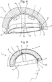
- Fig. 1 depicts a first helmet 1 of the sort discussed in WO 01/45526 , intended for providing protection against oblique impacts.
- This type of helmet could be any of the types of helmet discussed above.
- Protective helmet 1 is constructed with an outer shell 2 and, arranged inside the outer shell 2, an inner shell 3 that is intended for contact with the head of the wearer.
- a sliding layer 4 or a sliding facilitator Arranged between the outer shell 2 and the inner shell 3 is a sliding layer 4 or a sliding facilitator, and thus makes possible displacement between the outer shell 2 and the inner shell 3.
- a sliding layer 4 or sliding facilitator may be configured such that sliding may occur between two parts during an impact.
- it may be configured to enable sliding under forces associated with an impact on the helmet 1 that is expected to be survivable for the wearer of the helmet 1.
- it may be desirable to configure the sliding layer or sliding facilitator such that the coefficient of friction is between 0.001 and 0.3 and/or below 0.15.
- connecting members 5 Arranged in the edge portion of the helmet 1, in the Fig. 1 depiction, may be one or more connecting members 5 which interconnect the outer shell 2 and the inner shell 3.
- the connectors may counteract mutual displacement between the outer shell 2 and the inner shell 3 by absorbing energy. However, this is not essential. Further, even where this feature is present, the amount of energy absorbed is usually minimal in comparison to the energy absorbed by the inner shell 3 during an impact. In other arrangements, connecting members 5 may not be present at all.
- connecting members 5 can be varied (for example, being positioned away from the edge portion, and connecting the outer shell 2 and the inner shell 3 through the sliding layer 4).
- the outer shell 2 is preferably relatively thin and strong so as to withstand impact of various types.
- the outer shell 2 could be made of a polymer material such as polycarbonate (PC), polyvinylchloride (PVC) or acrylonitrile butadiene styrene (ABS) for example.
- the polymer material can be fibre-reinforced, using materials such as glass-fibre, Aramid, Twaron TM carbon-fibre or Kevlar TM .
- the inner shell 3 is considerably thicker and acts as an energy absorbing layer. As such, it is capable of damping or absorbing impacts against the head. It can advantageously be made of foam material like expanded polystyrene (EPS), expanded polypropylene (EPP), expanded polyurethane (EPU), vinyl nitrile foam; or other materials forming a honeycomb-like structure, for example; or strain rate sensitive foams such as marketed under the brand-names Poron TM and D3O TM .
- the construction can be varied in different ways, which emerge below, with, for example, a number of layers of different materials.
- Inner shell 3 is designed for absorbing the energy of an impact.
- Other elements of the helmet 1 will absorb that energy to a limited extend (e.g. the hard outer shell 2 or so-called 'comfort padding' provided within the inner shell 3), but that is not their primary purpose and their contribution to the energy absorption is minimal compared to the energy absorption of the inner shell 3.
- comfort padding may be made of 'compressible' materials, and as such considered as 'energy absorbing' in other contexts, it is well recognised in the field of helmets that compressible materials are not necessarily 'energy absorbing' in the sense of absorbing a meaningful amount of energy during an impact, for the purposes of reducing the harm to the wearer of the helmet.
- sliding layer 4 or sliding facilitator for example oil, Teflon, microspheres, air, rubber, polycarbonate (PC), a fabric material such as felt, etc.
- a layer may have a thickness of roughly 0.1-5 mm, but other thicknesses can also be used, depending on the material selected and the performance desired.
- the number of sliding layers and their positioning can also be varied, and an example of this is discussed below (with reference to Fig. 3B ).
- connecting members 5 use can be made of, for example, deformable strips of plastic or metal which are anchored in the outer shell and the inner shell in a suitable manner.
- Fig. 2 shows the functioning principle of protective helmet 1, in which the helmet 1 and a skull 10 of a wearer are assumed to be semi-cylindrical, with the skull 10 being mounted on a longitudinal axis 11. Torsional force and torque are transmitted to the skull 10 when the helmet 1 is subjected to an oblique impact K.
- the impact force K gives rise to both a tangential force K T and a radial force K R against the protective helmet 1.
- only the helmet-rotating tangential force K T and its effect are of interest.
- the force K gives rise to a displacement 12 of the outer shell 2 relative to the inner shell 3, the connecting members 5 being deformed.
- a reduction in the torsional force transmitted to the skull 10 of roughly 25% can be obtained with such an arrangement. This is a result of the sliding motion between the inner shell 3 and the outer shell 2 reducing the amount of energy which is transferred into radial acceleration.
- Sliding motion can also occur in the circumferential direction of the protective helmet 1, although this is not depicted. This can be as a consequence of circumferential angular rotation between the outer shell 2 and the inner shell 3 (i.e. during an impact the outer shell 2 can be rotated by a circumferential angle relative to the inner shell 3).
- the inner shell 3 is constructed from a relatively thin outer layer 3" and a relatively thick inner layer 3'.
- the outer layer 3" is preferably harder than the inner layer 3', to help facilitate the sliding with respect to outer shell 2.
- the inner shell 3 is constructed in the same manner as in Fig. 3a . In this case, however, there are two sliding layers 4, between which there is an intermediate shell 6.
- the two sliding layers 4 can, if so desired, be embodied differently and made of different materials.
- One possibility, for example, is to have lower friction in the outer sliding layer than in the inner.
- the outer shell 2 is embodied differently to previously. In this case, a harder outer layer 2" covers a softer inner layer 2'.
- the inner layer 2' may, for example, be the same material as the inner shell 3.
- Fig. 4 depicts a second helmet 1 of the sort discussed in WO 2011/139224 , which is also intended for providing protection against oblique impacts.
- This type of helmet could also be any of the types of helmet discussed above.
- helmet 1 comprises an energy absorbing layer 3, similar to the inner shell 3 of the helmet of Fig. 1 .
- the outer surface of the energy absorbing layer 3 may be provided from the same material as the energy absorbing layer 3 (i.e. there may be no additional outer shell), or the outer surface could be a rigid shell 2 (see Fig. 5 ) equivalent to the outer shell 2 of the helmet shown in Fig. 1 .
- the rigid shell 2 may be made from a different material than the energy absorbing layer 3.
- the helmet 1 of Fig. 4 has a plurality of vents 7, which are optional, extending through both the energy absorbing layer 3 and the outer shell 2, thereby allowing airflow through the helmet 1.
- An attachment device 13 is provided, for attachment of the helmet 1 to a wearer's head. As previously discussed, this may be desirable when energy absorbing layer 3 and rigid shell 2 cannot be adjusted in size, as it allows for the different size heads to be accommodated by adjusting the size of the attachment device 13.
- the attachment device 13 could be made of an elastic or semi-elastic polymer material, such as PC, ABS, PVC or PTFE, or a natural fibre material such as cotton cloth. For example, a cap of textile or a net could form the attachment device 13.
- the attachment device 13 is shown as comprising a headband portion with further strap portions extending from the front, back, left and right sides, the particular configuration of the attachment device 13 can vary according to the configuration of the helmet. In some cases the attachment device may be more like a continuous (shaped) sheet, perhaps with holes or gaps, e.g. corresponding to the positions of vents 7, to allow air-flow through the helmet.
- Fig. 4 also depicts an optional adjustment device 6 for adjusting the diameter of the head band of the attachment device 13 for the particular wearer.
- the head band could be an elastic head band in which case the adjustment device 6 could be excluded.
- a sliding facilitator 4 is provided radially inwards of the energy absorbing layer 3.
- the sliding facilitator 4 is adapted to slide against the energy absorbing layer or against the attachment device 13 that is provided for attaching the helmet to a wearer's head.
- the sliding facilitator 4 is provided to assist sliding of the energy absorbing layer 3 in relation to an attachment device 13, in the same manner as discussed above.
- the sliding facilitator 4 may be a material having a low coefficient of friction, or may be coated with such a material.
- the sliding facilitator may be provided on or integrated with the innermost sided of the energy absorbing layer 3, facing the attachment device 13.
- the sliding facilitator 4 may be provided on or integrated with the outer surface of the attachment device 13, for the same purpose of providing slidability between the energy absorbing layer 3 and the attachment device 13. That is, in particular arrangements, the attachment device 13 itself can be adapted to act as a sliding facilitator 4 and may comprise a low friction material.
- the sliding facilitator 4 is provided radially inwards of the energy absorbing layer 3.
- the sliding facilitator can also be provided radially outwards of the attachment device 13.
- sliding facilitators 4 may be provided as patches of low friction material.
- the low friction material may be a waxy polymer, such as PTFE, ABS, PVC, PC, Nylon, PFA, EEP, PE and UHMWPE, or a powder material which could be infused with a lubricant.
- the low friction material could be a fabric material. As discussed, this low friction material could be applied to either one, or both of the sliding facilitator and the energy absorbing layer
- the attachment device 13 can be fixed to the energy absorbing layer 3 and/ or the outer shell 2 by means of fixing members 5, such as the four fixing members 5a, 5b, 5c and 5d in Fig. 4 .
- fixing members 5 such as the four fixing members 5a, 5b, 5c and 5d in Fig. 4 .
- These may be adapted to absorb energy by deforming in an elastic, semi-elastic or plastic way. However, this is not essential. Further, even where this feature is present, the amount of energy absorbed is usually minimal in comparison to the energy absorbed by the energy absorbing layer 3 during an impact.
- the four fixing members 5a, 5b, 5c and 5d are suspension members 5a, 5b, 5c, 5d, having first and second portions 8, 9, wherein the first portions 8 of the suspension members 5a, 5b, 5c, 5d are adapted to be fixed to the attachment device 13, and the second portions 9 of the suspension members 5a, 5b, 5c, 5d are adapted to be fixed to the energy absorbing layer 3.
- Fig. 5 shows an embodiment of a helmet similar to the helmet in Fig. 4 , when placed on a wearers' head.
- the helmet 1 of Fig. 5 comprises a hard outer shell 2 made from a different material than the energy absorbing layer 3.
- the attachment device 13 is fixed to the energy absorbing layer 3 by means of two fixing members 5a, 5b, which are adapted to absorb energy and forces elastically, semi-elastically or plastically.
- a frontal oblique impact I creating a rotational force to the helmet is shown in Fig. 5 .
- the oblique impact I causes the energy absorbing layer 3 to slide in relation to the attachment device 13.
- the attachment device 13 is fixed to the energy absorbing layer 3 by means of the fixing members 5a, 5b.
- the fixing members 5 can absorb the rotational forces by deforming elastically or semi-elastically. In other arrangements, the deformation may be plastic, even resulting in the severing of one or more of the fixing members 5. In the case of plastic deformation, at least the fixing members 5 will need to be replaced after an impact. In some case a combination of plastic and elastic deformation in the fixing members 5 may occur, i.e. some fixing members 5 rupture, absorbing energy plastically, whilst other fixing members deform and absorb forces elastically.
- the energy absorbing layer 3 acts as an impact absorber by compressing, in the same way as the inner shell of the Fig. 1 helmet. If an outer shell 2 is used, it will help spread out the impact energy over the energy absorbing layer 3.
- the sliding facilitator 4 will also allow sliding between the attachment device and the energy absorbing layer. This allows for a controlled way to dissipate energy that would otherwise be transmitted as rotational energy to the brain.
- the energy can be dissipated by friction heat, energy absorbing layer deformation or deformation or displacement of the fixing members.
- the reduced energy transmission results in reduced rotational acceleration affecting the brain, thus reducing the rotation of the brain within the skull.
- the risk of rotational injuries such as subdural haematomas, SDH, blood vessel rapturing, concussions and DAI is thereby reduced.
- a helmet is provided with an impact response adjustment mechanism that is configured to enable adjustment of the response of the relative displacement between the inner shell and the outer shell in the event of an impact on the helmet.
- the displacement between the inner shell and the outer shell may be implemented by the provision of a sliding interface between the two shells.
- other arrangements may be provided, including but not limited to the provision of one or more components between the two shells that shear. It will be appreciated that, in such an arrangement, the inner and the outer surface of the one or more shearing components may be considered to be sliding relative to each other, enabling sliding of the shells relative to each other.
- An adjustment mechanism may be configured such that a user can make adjustments in a controlled manner, for example enabling them to make an adjustment with an understanding of the expected effect of an adjustment that they make. This may be distinct from variations in the performance of a helmet that may arise from natural variations in the process of assembling a helmet.
- the inner and outer shells of the helmet for which the impact response adjustment mechanism may adjust the relative displacement may, in general, be any two layers of a helmet between which a sliding interface, or other interface enabling relative displacement, is provided.
- such an impact response adjustment mechanism may be provided to any of the helmet arrangements discussed above.
- the inner shell may be a layer that is configured to contact the head of the wearer and/or to be mounted to the head of the wearer and the outer shell may be an energy absorbing layer for absorbing impact energy.
- the inner shell may be a first energy absorbing layer for absorbing impact energy and the outer shell may be a second energy absorbing layer for absorbing impact energy.
- the inner shell may be an energy absorbing layer for absorbing impact energy and the outer shell may be a relatively hard shell, for example formed from a material that is harder than the material used to form the energy absorbing layer.
- the impact response adjustment mechanism may be configured such that it can be manually adjusted by a wearer of the helmet. Accordingly, the adjustment of the impact response adjustment mechanism may be performed after a user has purchased a helmet rather than being set, for example, in the manufacturing/assembly process. A user may also be able to repeatedly adjust the impact response adjustment mechanism to different settings.
- a tool may be used in order to adjust the impact response adjustment mechanism.
- the impact response adjustment mechanism may be configured such that the user can adjust the setting of the impact response adjustment mechanism without requiring the use of a tool.
- the impact response adjustment mechanism may be configured such that changing the setting of the impact response adjustment mechanism may be effected using their hand/fingers.
- an impact response adjustment mechanism may be provided at any convenient point on a helmet.
- the impact response adjustment mechanism may be provided at the edge of a helmet. This may be convenient for providing access for a user to the impact response adjustment mechanism. For example, this may permit the user to change the setting of the impact response adjustment mechanism while wearing the helmet.
- providing an impact response adjustment mechanism at an edge of a helmet may facilitate the manufacture of a helmet with such an impact response adjustment mechanism.
- the impact response adjustment mechanism may enable adjustment of the response profile of the relative displacement over time between the inner shell and the outer shell. Accordingly, for a given magnitude of impact at a specific location on the helmet, a characteristic profile of the displacement over time of the outer shell relative to the inner shell over time may be altered by changing the setting of the impact response adjustment mechanism. Depending on the impact response adjustment mechanism used, the effect of the change may be to change at least one of the maximum relative velocity, the maximum rate of change of the relative velocity, namely the relative acceleration, the time above a threshold relative velocity and the time above a threshold relative acceleration.
- the comparison of the effect of the performance of a helmet for different settings of the impact response adjustment mechanism may be understood by considering the change of the response profile of the relative displacement over time between the inner shell and the outer shell for a given magnitude of impact at a specific location on the helmet.
- Such an impact may be a standard impact, namely of a standard impact force at a standard location.
- the effect of changing the setting of the impact response adjustment mechanism in a helmet may also be such that, for the different settings, the helmet may be able to withstand different levels of impact whilst having the same, or a similar, response profile of the relative displacement over time between the inner shell and the outer shell.
- the impact response adjustment mechanism includes a friction pad that is mounted on one of the inner shell and the outer shell and contacts an opposing surface on the other of the inner shell and the outer shell.
- the impact response adjustment mechanism may be configured such that changing the setting of the impact response adjustment mechanism adjusts the friction force between the friction pad and the opposing surface. In so doing, the response profile of the relative displacement over time of the outer shell relative to the inner shell is also adjusted.
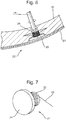
- Figure 6 depicts an arrangement of an impact response adjustment mechanism 20 that includes a friction pad 25 mounted on the inner shell 22 of a helmet.
- the surface of the friction pad 25 is arranged to oppose an inner surface of the outer shell 21.
- the friction pad 25 may include a surface having a coefficient of friction with the opposing surface that may be higher than the coefficient friction between the inner shell and the outer shell at the sliding interface.
- the friction pad 25 may also include a resilient portion, configured such that the further the resilient portion is advanced towards the opposing surface, the greater the reaction force between the surface of the friction pad 25 and the opposing surface.
- a rotating actuator 26 is provided in conjunction with the friction pad 25.
- the friction pad 25 is advanced towards the opposing surface of the outer shell 21.
- the friction pad 25 is retracted away from the opposing surface of the outer shell 21. Accordingly, by adjusting the rotating actuator 26, the reaction force between the friction pad 25 and the opposing surface of the outer shell 21 may be changed, which in turn changes the response profile of the relative displacement over time of the outer shell in relation to the inner shell in response to an impact on the helmet.
- the impact response adjustment mechanism 20 is mounted to the inner shell 22 and includes a friction pad 25 that opposes the inner surface of the outer shell 21, the arrangement may be reversed. Accordingly, the impact response adjustment mechanism 20 may be mounted to the outer shell 21 and have a friction pad 25 that opposes an outer surface of the inner shell 22.
- the rotating actuator is depicted being adjusted by use of a tool 27, it should be appreciated, that in a variation, the rotating actuator 26 may be configured to be adjusted without the use of a tool. For example, it may have an integral user interface that can be adjusted manually by a user.
- the impact response adjustment mechanism 20 may be configured such that the rotating actuator 26 is adjusted from the side of the sliding interface that corresponds to the shell on which it is mounted, variations are possible.
- the arrangement depicted in Figure 6 may be modified to include an opening through the outer shell 21 and the friction pad 25 that permit a tool 27 to be inserted from outside the helmet and to engage with the rotating actuator 26 in order to adjust the setting of the impact response adjustment mechanism 20.
- the impact response adjustment mechanism may comprise a controller that is configured to be operated by a user and may, in turn, control the friction pad to adjust the reaction force between the friction pad and the opposing surface.
- the controller may be part of, or used in conjunction with, the rotating actuator 26. In other arrangements, the controller may be separated from the friction pad 25. Such an arrangement may enable the friction pad to be mounted at a location that is desirable for the operation of the impact response adjustment mechanism but for the controller to be provided at a location that is convenient for access by the user.
- the impact response adjustment mechanism may include at least one tensile element, such as a wire, band or tape that provides a connection between the controller and the friction pad.
- the controller may be configured such that it can adjust the tension in the wire, band or tape.
- the friction pad may be arranged such that the tension in the wire, band or tape determines the reaction force between the friction pad and the opposing surface against which it acts. Accordingly, by means of adjusting the controller, a user may adjust the friction between the inner and outer shell, adjusting the response profile of the relative displacement over time of the outer shell in relation to the inner shell in response to an impact on the helmet.
- the controller may be provided by one of a number of arrangements.
- a controller 31 such as that depicted in Figure 7 may be used.
- the controller 31 may include a rotatably mounted spool 32 about which the wire, band or tape 33 may be wound.
- a control knob 34 may be connected to the spool 32.
- the user may turn the knob 34 in order to wind on, or wind off, the wire, band or tape 33 from the spool 32, adjusting the tension of the wire, band or tape.
- a ratchet or other similar mechanism may be provided arranged such that, when the user has set the control knob 34 to the desired position, it remains in the desired position when the user releases the control knob 34, maintaining the desired tension in the wire, band or tape 33.
- the wire, band or tape may engage with a friction pad 25 such that applying tension to the wire, band or tape 33 forces the friction pad 25 towards the opposing surface.
- the wire, band or tape may be arranged to be diverted around a part of the friction pad 25.
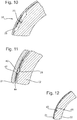
- the force has the effect of trying to straighten the wire, band or tape 33, forcing the friction pad 25 to one side, namely in the arrangement depicted in Figure 8 , towards the inner surface of the outer shell 21.
- reverse configurations may be made, namely in which increasing the tension in the wire, band or tape 33 forces a friction pad 25 mounted on the outer shell 21 towards the outer surface of the inner shell 22.
- Figure 9 depicts a further possible variation of an arrangement using a wire, band or tape 33.
- the wire, band or tape 33 may be a relatively stiff element that is constrained by the friction pad 25 and the surrounding parts of the shell to which the friction pad 25 is mounted such that it biases the friction pad 25 towards the opposing surface.
- the friction pad 25 is mounted on the inner shell 22 and the stiff wire, band or tape 33 biases the friction pad 25 towards the inner surface of the outer shell 21.
- Application of a tensile force to the stiff wire, band or tape 33 may reduce the reaction force between the friction pad 25 and the inner surface of the outer shell 21. If the tensile force applied to the stiff wire, band or tape 33 is sufficient, the friction pad 25 may be completely retracted from the opposing surface, namely such that it no longer contacts the inner surface of the outer shell 21.
- a friction pad 35 may be provided that is configured such that, when the tension in the wire, band or tape 33 is increased, the shape of the friction pad 35 changes.
- the friction pad 35 may be formed from a pocket of resilient material 36, bounding a portion of the wire, band or tape 33. When the tension in the wire, band or tape 33 increases, it may act against the section of resilient material 36, changing the shape of the friction pad 35, in particular such that the outer surface of the friction pad 35 presses against the opposing surface or presses against it more strongly.
- the impact response adjustment mechanism 20 may include a plurality of friction pads.
- a plurality of friction pads may be connected to a wire, band or tape 33 such that adjusting the tension in the wire, band or tape controls the reaction force between the plurality of friction pads 25 and respective surfaces opposing the friction pads.
- the impact response adjustment mechanism 20 may include a plurality of wires, bands or tapes 33, each connected to at least one friction pad 25. Accordingly, a user adjusting the setting of the impact response adjustment mechanism on a single controller may adjust the tension within a plurality of wires, bands or tapes, and, as a result, the reaction force between the friction pads and the respective opposing surfaces.
- a tube may be provided between a controller and one or more friction pads.
- the controller may be configured such that a user may use the controller to adjust the pressure of a fluid such as air, within the tube.
- the impact response adjustment mechanism may be configured such that the pressure in the tube determines the reaction force between the one or more friction pads and the opposing surface.
- Figure 11 depicts an example of an arrangement in which the reaction force exerted by a friction pad is controlled by pressure.
- the friction pad 25 includes an inflatable bladder 45 connected to the outer shell 21. As the pressure inside the inflatable bladder 45 is increased, the reaction force between it and the inner shell 22 is increased.
- a low friction layer 46 is provided between the inner shell 22 and the outer shell 21 in order to facilitate sliding between the two shells.
- the inflatable bladder 45 may be provided at, and partially protrude through, an opening 47 in the low friction layer 46. It should be appreciated that, in an alternative arrangement, the inflatable bladder may be connected to the inner shell 22.
- a part of the surface of the tube 40 may function as a friction pad.
- the tube 40 may be mounted within a recess 41 within one of the inner shell 22 and the outer shell 21 and may be formed from a resilient material. Accordingly, as the pressure in the tube 40 increases, the tube 40 expands, which may control the reaction force between part of the tube 40 and an opposing surface.
- the tube 40 is mounted within a recess 41 within the inner shell 22 and the opposing surface is the inner surface of the outer shell 21. It will be appreciated that this arrangement may readily be reversed.
- a controller that is configured to adjust the pressure within a tube 40 may be connected to, and control the pressure within, a plurality of tubes.
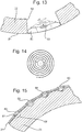
- Figure 13 depicts an alternative arrangement of an impact response adjustment mechanism.
- the impact response adjustment mechanism includes a deformable member 51 mounted to one of the inner and the outer shell (in the arrangement shown the outer shell 21) and arranged within an opening 52 in the other shell (in the arrangement shown the opening 52 is within the inner shell 22).
- a surface of the deformable member 51 may engage with the surface of the opening 52, affecting the sliding of one shell relative to another as the deformable member 51 deforms.
- the inner and outer shells 21, 22 may slide relative to one another for a distance corresponding to the initial separation before contact is made between the deformable member 51 and the surface of the opening 52. Accordingly, for an initial distance, the inner and outer shells, 22 may slide relative to one another without interference. At the point at which the deformable member 51 contacts the surface of the opening 52, the sliding of the inner shell relative to the outer shell 22 will be restricted by the extent to which the deformable member 51 deforms.
- the impact response adjustment mechanism including a deformable member 51 may include a controller 53 that can deform the deformable member 51 in order to provide a desired setting of the impact response adjustment mechanism.
- the controller 53 may deform the shape of the deformable member 51 in order to control the initial separation between an edge of the deformable member 51 and the edge of the opening 52. This may control the extent to which the inner and outer shells 21, 22, may slide relative to one another before the engagement between the deformable member 51 and the edge of the opening 52 starts to affect the sliding of the outer shell 21 relative to the inner shell 22.
- the adjustment by the controller 53 may adjust the pre-stress applied to the deformable member 51.
- the higher the level of pre-stress applied to the deformable member 51 the greater the force that must be applied to the deformable member 51 by the edge of the opening 52 in order to compress the deformable member 51 a given distance. Accordingly, this may adjust the response profile of the relative displacement over time of the inner and outer shells in response to an impact on the helmet.
- the deformable member 51 may be in contact with the edge of the opening 52 for the full range of settings available to be set by the controller 53. Accordingly, the controller may purely control the pre-stress applied to the deformable member 51.
- controller 53 may adjust the shape of the deformable member 51 in order to adjust the initial separation between the edge of the deformable member 51 and the opening 52.
- the deformable member 51 may be formed from a single piece of a deformable material such as an elastomer. Alternatively or additionally, as shown in Figure 14 , the deformable member 51 may include an element such as flat coil spring.
- the impact response adjustment mechanism may include a removable stud that is configured to be removably inserted into a socket in one of the inner shell and outer shell.
- the impact response adjustment mechanism may be configured such that a part of the stud may engage with a surface on the other of the inner and the outer shell in the event of an impact on the helmet in order to affect the relative sliding of the inner and the outer shell.
- the outer shell 21 may include one or more sockets 61, into which a stud 62 may be removably inserted. Part of the stud 62 may protrude into a recess 66 in the inner shell 22.
- the recess 66 may be arranged such that it is opposite the socket 61 in normal use of the helmet, namely when the helmet has not been subjected to an impact.
- the outer shell 21 may slide relative to the inner shell 22, whereupon the stud 62 may engage with an edge of the recess 66 in the inner shell 22.
- the engagement of the stud 62 with the edge of the recess 66 may restrict or otherwise affect the sliding of the outer shell 21 relative to the inner shell 22.
- the removable stud 62 may be removed and replaced with a different stud 63, 64, 65.
- the different studs may have different shapes, for example different sized protrusions as depicted in Figure 15 and/or may have different harnesses.
- a helmet may have a single socket and the user may select one from a plurality of studs to insert in the socket or may insert no studs in the socket in order to provide the helmet with a desired setting of the impact response adjustment mechanism.
- a helmet may have a plurality of sockets and the user may select desired studs for one or more of those sockets as appropriate.
- a user may be provided with a sufficient number of studs of each type that each socket may be provided with the same type of stud.
- the sockets may be simple holes, through which deformable studs may be forced in order to attach or remove the studs from the sockets.
- other attachment arrangements may be provided, such as, for example, providing the sockets and studs with threaded sections such that the studs can be removably screwed into the socket.
Landscapes
- Helmets And Other Head Coverings (AREA)
Claims (15)
- Casque (1) comprenant :une coque interne (22) ;une coque externe (21), configurée pour pouvoir se déplacer par rapport à la coque interne (22) en réponse à un impact ;une interface coulissante entre la coque interne (22) et la coque externe (21) ; etcaractérisé en ce qu'il comprend en outre :
un mécanisme de réglage de la réponse à l'impact configuré pour être réglable de telle sorte que le profil de réponse du déplacement relatif dans le temps de la coque externe (21) par rapport à la coque interne (22) en réponse à un impact sur le casque (1) varie en fonction du réglage du mécanisme de réglage de la réponse à l'impact. - Casque (1) selon la revendication 1, dans lequel le mécanisme de réglage de la réponse à l'impact comprend un patin de friction (25) monté sur l'une parmi la coque interne (22) et la coque externe (21) ;le patin de friction (25) est configuré pour être en contact avec une surface opposée formée sur, ou connectée à, l'une de la coque interne (22) et de la coque externe (21) à laquelle la surface de friction n'est pas connectée ; etle mécanisme de réglage de la réponse à l'impact est configuré de telle sorte qu'il puisse régler le frottement entre le patin de friction (25) et la surface opposée pour régler le profil de réponse du déplacement relatif dans le temps de la coque externe (21) par rapport à la coque interne (22) en réponse à un impact sur le casque (1).
- Casque (1) selon la revendication 2, dans lequel le mécanisme de réglage de la réponse à l'impact est configuré pour pouvoir régler la force de réaction entre le patin de friction (25) et la surface opposée.
- Casque (1) selon la revendication 3, dans lequel le mécanisme de réglage de la réponse à l'impact comprend un actionneur rotatif (26) qui, lors d'une rotation dans des premier et deuxième directions respectives, rétracte et avance le patin de friction (25) afin de régler la force de réaction entre le patin de friction (25) et la surface opposée.
- Casque (1) selon l'une quelconque des revendications 2 à 3, dans lequel le mécanisme de réglage de la réponse à l'impact comprend un contrôleur (31) configuré pour être actionné par un utilisateur ;
dans lequel le contrôleur (31) est configuré pour contrôler le patin de friction (25) pour ajuster la force de réaction entre le patin de friction (25) et la surface opposée. - Casque (1) selon la revendication 5, dans lequel le mécanisme de réglage de la réponse à l'impact comprend un fil, une bande ou un ruban (33) connectant le contrôleur (31) et le patin de friction (25) ; et
la tension dans le fil, la bande ou le ruban (33) détermine la force de réaction entre le patin de friction (25) et la surface opposée. - Casque (1) selon la revendication 6, dans lequel le mécanisme de réglage de la réponse à l'impact comprend une pluralité de patins de friction (25) et le fil, la bande ou le ruban (33) est connecté à une pluralité desdits patins de friction (25) ;
dans lequel éventuellement le contrôleur (31) est connecté à une pluralité de fils, bandes ou rubans (33), dont chacun est connecté à au moins un patin de friction (25). - Casque (1) selon la revendication 5, dans lequel le mécanisme de réglage de la réponse à l'impact comprend un tube (40) connectant le contrôleur (31) et le patin de friction (25) ; etle mécanisme de réglage de la réponse à l'impact est configuré de telle sorte que la pression dans le tube (40) détermine la force de réaction entre le patin de friction (25) et la surface opposée ;dans lequel éventuellement la surface du tube (40) forme un patin de friction ;dans lequel éventuellement le contrôleur (31) est connecté à une pluralité de tubes (40), dont chacun est connecté à au moins un patin de friction (25).
- Casque (1) selon l'une quelconque des revendications précédentes, dans lequel le mécanisme de réglage de la réponse à l'impact comprend un élément déformable (51) monté sur une surface de l'une de la coque interne (22) et de la coque externe (21) à une interface entre les coques et à l'intérieur d'une ouverture (52) formée dans l'autre de la coque interne (22) et de la coque externe (21) ; et
l'élément de réglage de réponse à l'impact est configuré de telle sorte qu'après un impact sur le casque (1) qui provoque le déplacement de la coque externe (21) par rapport à la coque interne (22), l'élément déformable (51) exerce une force sur les parois latérales de l'ouverture (52). - Casque (1) selon la revendication 9, dans lequel l'élément déformable (51) est en contact avec les parois de l'ouverture (52) en l'absence d'impact sur le casque (1) qui provoque la coque externe (21) à se déplacer par rapport à la coque interne (22) ;
ou dans lequel le mécanisme de réglage de la réponse à l'impact est configuré de telle sorte que l'élément déformable (51) peut être déformé pour ajuster la séparation entre le bord de l'élément déformable (51) et les parois latérales de l'ouverture (52) en l'absence d'impact sur le casque (1) qui provoque le déplacement de la coque externe (21) par rapport à la coque interne (22). - Casque (1) selon l'une quelconque des revendications 9 à 10, dans lequel le mécanisme de réglage de la réponse à l'impact est configuré de telle sorte qu'il puisse régler une précontrainte appliquée à l'élément déformable (52) en l'absence d'impact sur le casque (1) qui provoque le déplacement de la coque externe (21) par rapport à la coque interne (22).
- Casque (1) selon l'une quelconque des revendications précédentes, dans lequel le mécanisme de réglage de la réponse à l'impact comprend une douille (61) disposée dans au moins l'une de la coque interne (22) et de la coque externe (21) ;
un goujon amovible (62), configuré pour être inséré de manière amovible dans la douille (61) ; et le mécanisme de réglage de la réponse à l'impact est configuré de telle sorte qu'après un impact sur le casque (1) qui provoque le déplacement de la coque externe (21) par rapport à la coque interne (22), le goujon (62) entre en contact avec une surface opposée sur l'une de la coque interne (22) et de la coque externe (21) qui ne comprend pas la douille (61). - Casque (1) selon la revendication 12, comprenant une pluralité de goujons (62, 63, 64, 65) de formes et/ou duretés différentes, dont l'un quelconque peut être inséré de manière amovible dans ladite douille (61) ;
dans lequel éventuellement le mécanisme de réglage de la réponse à l'impact comprend une pluralité desdites douilles (61). - Casque (1) selon l'une quelconque des revendications précédentes, dans lequel le mécanisme de réglage de la réponse à l'impact est configuré pour être réglable manuellement par un porteur du casque (1) ;
dans lequel éventuellement le mécanisme de réglage de la réponse à l'impact est configuré pour être réglable sans nécessiter l'utilisation d'un outil. - Casque (1) selon l'une quelconque des revendications précédentes, dans lequel la coque interne (22) est configurée pour entrer en contact avec la tête d'un porteur, et la coque externe (21) est une coque absorbant l'énergie pour absorber l'énergie d'impact ; oudans lequel la coque interne (22) est une première coque d'absorption d'énergie pour absorber l'énergie d'impact et la coque externe (21) est une deuxième coque d'absorption d'énergie pour absorber l'énergie d'impact ;ou dans lequel la coque interne (22) est une coque absorbant l'énergie pour absorber l'énergie d'impact et la coque externe (21) est une coque dure formée d'un matériau dur par rapport à un matériau formant la coque absorbant l'énergie.
Applications Claiming Priority (2)
| Application Number | Priority Date | Filing Date | Title |
|---|---|---|---|
| GBGB1800255.0A GB201800255D0 (en) | 2018-01-08 | 2018-01-08 | Helmet |
| PCT/EP2019/050173 WO2019134974A1 (fr) | 2018-01-08 | 2019-01-04 | Casque |
Publications (2)
| Publication Number | Publication Date |
|---|---|
| EP3737253A1 EP3737253A1 (fr) | 2020-11-18 |
| EP3737253B1 true EP3737253B1 (fr) | 2021-12-08 |
Family
ID=61190367
Family Applications (1)
| Application Number | Title | Priority Date | Filing Date |
|---|---|---|---|
| EP19700252.0A Active EP3737253B1 (fr) | 2018-01-08 | 2019-01-04 | Casque |
Country Status (7)
| Country | Link |
|---|---|
| US (1) | US11812810B2 (fr) |
| EP (1) | EP3737253B1 (fr) |
| CN (1) | CN111770698B (fr) |
| ES (1) | ES2902948T3 (fr) |
| GB (1) | GB201800255D0 (fr) |
| TW (1) | TWI693036B (fr) |
| WO (1) | WO2019134974A1 (fr) |
Families Citing this family (5)
| Publication number | Priority date | Publication date | Assignee | Title |
|---|---|---|---|---|
| GB2592872B (en) * | 2019-11-04 | 2023-03-08 | Globus Shetland Ltd | Safety helmet |
| EP3838043B1 (fr) * | 2019-12-18 | 2023-08-16 | George TFE SCP | Casque |
| USD1004850S1 (en) | 2021-03-17 | 2023-11-14 | Studson, Inc. | Protective helmet |
| USD995925S1 (en) | 2020-09-23 | 2023-08-15 | Studson, Inc. | Protective helmet |
| USD995924S1 (en) | 2021-03-17 | 2023-08-15 | Studson, Inc. | Protective helmet |
Family Cites Families (25)
| Publication number | Priority date | Publication date | Assignee | Title |
|---|---|---|---|---|
| GB9423113D0 (en) | 1994-11-16 | 1995-01-04 | Phillips Kenneth D | Protective headgear |
| US6658671B1 (en) | 1999-12-21 | 2003-12-09 | Neuroprevention Scandinavia Ab | Protective helmet |
| JP3765377B2 (ja) * | 2000-04-04 | 2006-04-12 | 本田技研工業株式会社 | ヘルメット |
| CA2401929C (fr) | 2002-09-09 | 2010-11-09 | Ione G. Puchalski | Casque de sport comprenant une zone de cisaillement ou de froissement qui absorbe les impacts |
| US20040117896A1 (en) * | 2002-10-04 | 2004-06-24 | Madey Steven M. | Load diversion method and apparatus for head protective devices |
| US20040250340A1 (en) * | 2003-02-05 | 2004-12-16 | Dennis Piper | Protective headguard |
| US8316512B2 (en) | 2007-02-20 | 2012-11-27 | Mips Ab | Apparatus at a protective helmet |
| SE536246C2 (sv) * | 2010-01-13 | 2013-07-16 | Mips Ab | Mellanliggande lager av friktionsminskande material |
| SE534868C2 (sv) | 2010-05-07 | 2012-01-24 | Mips Ab | Hjälm med glidningsfrämjare anordnad vid ett energiabsorberande lager |
| DE102011112790A1 (de) | 2010-09-09 | 2012-03-15 | Oliver Schimpf | Schutzhelm; Verfahren zur Verminderung oder Verhinderung einer Kopfverletzung |
| CN103635112B (zh) | 2011-02-09 | 2015-12-23 | 6D头盔有限责任公司 | 头盔全向能量管理系统 |
| US9439469B2 (en) * | 2011-09-08 | 2016-09-13 | Emerson Spalding Phipps | Protective helmet |
| US9388873B1 (en) | 2011-09-08 | 2016-07-12 | Emerson Spalding Phipps | Torso protection system |
| US9089180B2 (en) | 2011-09-08 | 2015-07-28 | Emerson Spalding Phipps | Protective helmet |
| US9980531B2 (en) | 2012-03-06 | 2018-05-29 | Loubert S. Suddaby | Protective helmet with energy storage mechanism |
| US9021616B2 (en) | 2012-04-25 | 2015-05-05 | David Baty | Protective gear |
| US20140013492A1 (en) | 2012-07-11 | 2014-01-16 | Apex Biomedical Company Llc | Protective helmet for mitigation of linear and rotational acceleration |
| GB201409041D0 (en) * | 2014-05-21 | 2014-07-02 | Leatt Corp | Helmet |
| US9408423B2 (en) * | 2014-09-25 | 2016-08-09 | David A. Guerra | Impact reducing sport equipment |
| US10729200B2 (en) | 2014-11-11 | 2020-08-04 | The Uab Research Foundation | Protective helmets having energy absorbing tethers |
| US9918507B2 (en) | 2014-11-25 | 2018-03-20 | Charles Eaton | Protective helmet |
| WO2016209740A1 (fr) | 2015-06-17 | 2016-12-29 | 6D Helmets, Llc | Systèmes et procédés de gestion d'énergie omnidirectionnelle de casque |
| US10376010B2 (en) | 2015-11-04 | 2019-08-13 | Bell Sports, Inc. | Shock absorbing helmet |
| US20180153243A1 (en) * | 2016-12-05 | 2018-06-07 | Brainguard Technologies, Inc. | Adjustable elastic shear protection in protective gear |
| DE102017206897B4 (de) * | 2017-04-25 | 2021-02-04 | Robert Bosch Gmbh | Schutzhelm und Verfahren zur Herstellung eines Schutzhelms |
-
2018
- 2018-01-08 GB GBGB1800255.0A patent/GB201800255D0/en not_active Ceased
-
2019
- 2019-01-04 ES ES19700252T patent/ES2902948T3/es active Active
- 2019-01-04 CN CN201980015734.8A patent/CN111770698B/zh active Active
- 2019-01-04 WO PCT/EP2019/050173 patent/WO2019134974A1/fr unknown
- 2019-01-04 US US16/960,259 patent/US11812810B2/en active Active
- 2019-01-04 EP EP19700252.0A patent/EP3737253B1/fr active Active
- 2019-01-08 TW TW108100689A patent/TWI693036B/zh active
Also Published As
| Publication number | Publication date |
|---|---|
| WO2019134974A1 (fr) | 2019-07-11 |
| TW201929708A (zh) | 2019-08-01 |
| US20200359727A1 (en) | 2020-11-19 |
| TWI693036B (zh) | 2020-05-11 |
| CN111770698A (zh) | 2020-10-13 |
| US11812810B2 (en) | 2023-11-14 |
| CN111770698B (zh) | 2023-08-11 |
| EP3737253A1 (fr) | 2020-11-18 |
| GB201800255D0 (en) | 2018-02-21 |
| ES2902948T3 (es) | 2022-03-30 |
Similar Documents
| Publication | Publication Date | Title |
|---|---|---|
| EP3256016B1 (fr) | Casque, doublure de casque, rembourrage de confort destiné à un casque et élément de liaison | |
| EP3554298B1 (fr) | Casque | |
| EP3624625B1 (fr) | Casque | |
| EP3737253B1 (fr) | Casque | |
| EP3755172B1 (fr) | Raccord | |
| EP3873286B1 (fr) | Coussinet de joue pour casque | |
| CA3164964A1 (fr) | Raccord | |
| EP3737252B1 (fr) | Casque | |
| US20230037810A1 (en) | Helmet | |
| NZ759007B2 (en) | Helmet |
Legal Events
| Date | Code | Title | Description |
|---|---|---|---|
| STAA | Information on the status of an ep patent application or granted ep patent |
Free format text: STATUS: UNKNOWN |
|
| STAA | Information on the status of an ep patent application or granted ep patent |
Free format text: STATUS: THE INTERNATIONAL PUBLICATION HAS BEEN MADE |
|
| PUAI | Public reference made under article 153(3) epc to a published international application that has entered the european phase |
Free format text: ORIGINAL CODE: 0009012 |
|
| STAA | Information on the status of an ep patent application or granted ep patent |
Free format text: STATUS: REQUEST FOR EXAMINATION WAS MADE |
|
| 17P | Request for examination filed |
Effective date: 20200724 |
|
| AK | Designated contracting states |
Kind code of ref document: A1 Designated state(s): AL AT BE BG CH CY CZ DE DK EE ES FI FR GB GR HR HU IE IS IT LI LT LU LV MC MK MT NL NO PL PT RO RS SE SI SK SM TR |
|
| AX | Request for extension of the european patent |
Extension state: BA ME |
|
| DAV | Request for validation of the european patent (deleted) | ||
| DAX | Request for extension of the european patent (deleted) | ||
| GRAP | Despatch of communication of intention to grant a patent |
Free format text: ORIGINAL CODE: EPIDOSNIGR1 |
|
| STAA | Information on the status of an ep patent application or granted ep patent |
Free format text: STATUS: GRANT OF PATENT IS INTENDED |
|
| INTG | Intention to grant announced |
Effective date: 20210923 |
|
| GRAS | Grant fee paid |
Free format text: ORIGINAL CODE: EPIDOSNIGR3 |
|
| GRAA | (expected) grant |
Free format text: ORIGINAL CODE: 0009210 |
|
| STAA | Information on the status of an ep patent application or granted ep patent |
Free format text: STATUS: THE PATENT HAS BEEN GRANTED |
|
| AK | Designated contracting states |
Kind code of ref document: B1 Designated state(s): AL AT BE BG CH CY CZ DE DK EE ES FI FR GB GR HR HU IE IS IT LI LT LU LV MC MK MT NL NO PL PT RO RS SE SI SK SM TR |
|
| REG | Reference to a national code |
Ref country code: GB Ref legal event code: FG4D |
|
| REG | Reference to a national code |
Ref country code: AT Ref legal event code: REF Ref document number: 1453061 Country of ref document: AT Kind code of ref document: T Effective date: 20211215 Ref country code: CH Ref legal event code: EP |
|
| REG | Reference to a national code |
Ref country code: DE Ref legal event code: R096 Ref document number: 602019009926 Country of ref document: DE |
|
| REG | Reference to a national code |
Ref country code: IE Ref legal event code: FG4D |
|
| REG | Reference to a national code |
Ref country code: FI Ref legal event code: FGE |
|
| REG | Reference to a national code |
Ref country code: SE Ref legal event code: TRGR |
|
| REG | Reference to a national code |
Ref country code: NL Ref legal event code: FP |
|
| REG | Reference to a national code |
Ref country code: NO Ref legal event code: T2 Effective date: 20211208 |
|
| REG | Reference to a national code |
Ref country code: ES Ref legal event code: FG2A Ref document number: 2902948 Country of ref document: ES Kind code of ref document: T3 Effective date: 20220330 |
|
| REG | Reference to a national code |
Ref country code: LT Ref legal event code: MG9D |
|
| PG25 | Lapsed in a contracting state [announced via postgrant information from national office to epo] |
Ref country code: RS Free format text: LAPSE BECAUSE OF FAILURE TO SUBMIT A TRANSLATION OF THE DESCRIPTION OR TO PAY THE FEE WITHIN THE PRESCRIBED TIME-LIMIT Effective date: 20211208 Ref country code: LT Free format text: LAPSE BECAUSE OF FAILURE TO SUBMIT A TRANSLATION OF THE DESCRIPTION OR TO PAY THE FEE WITHIN THE PRESCRIBED TIME-LIMIT Effective date: 20211208 Ref country code: BG Free format text: LAPSE BECAUSE OF FAILURE TO SUBMIT A TRANSLATION OF THE DESCRIPTION OR TO PAY THE FEE WITHIN THE PRESCRIBED TIME-LIMIT Effective date: 20220308 |
|
| REG | Reference to a national code |
Ref country code: AT Ref legal event code: MK05 Ref document number: 1453061 Country of ref document: AT Kind code of ref document: T Effective date: 20211208 |
|
| PG25 | Lapsed in a contracting state [announced via postgrant information from national office to epo] |
Ref country code: LV Free format text: LAPSE BECAUSE OF FAILURE TO SUBMIT A TRANSLATION OF THE DESCRIPTION OR TO PAY THE FEE WITHIN THE PRESCRIBED TIME-LIMIT Effective date: 20211208 Ref country code: HR Free format text: LAPSE BECAUSE OF FAILURE TO SUBMIT A TRANSLATION OF THE DESCRIPTION OR TO PAY THE FEE WITHIN THE PRESCRIBED TIME-LIMIT Effective date: 20211208 Ref country code: GR Free format text: LAPSE BECAUSE OF FAILURE TO SUBMIT A TRANSLATION OF THE DESCRIPTION OR TO PAY THE FEE WITHIN THE PRESCRIBED TIME-LIMIT Effective date: 20220309 |
|
| PG25 | Lapsed in a contracting state [announced via postgrant information from national office to epo] |
Ref country code: SM Free format text: LAPSE BECAUSE OF FAILURE TO SUBMIT A TRANSLATION OF THE DESCRIPTION OR TO PAY THE FEE WITHIN THE PRESCRIBED TIME-LIMIT Effective date: 20211208 Ref country code: SK Free format text: LAPSE BECAUSE OF FAILURE TO SUBMIT A TRANSLATION OF THE DESCRIPTION OR TO PAY THE FEE WITHIN THE PRESCRIBED TIME-LIMIT Effective date: 20211208 Ref country code: RO Free format text: LAPSE BECAUSE OF FAILURE TO SUBMIT A TRANSLATION OF THE DESCRIPTION OR TO PAY THE FEE WITHIN THE PRESCRIBED TIME-LIMIT Effective date: 20211208 Ref country code: PT Free format text: LAPSE BECAUSE OF FAILURE TO SUBMIT A TRANSLATION OF THE DESCRIPTION OR TO PAY THE FEE WITHIN THE PRESCRIBED TIME-LIMIT Effective date: 20220408 Ref country code: EE Free format text: LAPSE BECAUSE OF FAILURE TO SUBMIT A TRANSLATION OF THE DESCRIPTION OR TO PAY THE FEE WITHIN THE PRESCRIBED TIME-LIMIT Effective date: 20211208 Ref country code: CZ Free format text: LAPSE BECAUSE OF FAILURE TO SUBMIT A TRANSLATION OF THE DESCRIPTION OR TO PAY THE FEE WITHIN THE PRESCRIBED TIME-LIMIT Effective date: 20211208 |
|
| PG25 | Lapsed in a contracting state [announced via postgrant information from national office to epo] |
Ref country code: PL Free format text: LAPSE BECAUSE OF FAILURE TO SUBMIT A TRANSLATION OF THE DESCRIPTION OR TO PAY THE FEE WITHIN THE PRESCRIBED TIME-LIMIT Effective date: 20211208 Ref country code: AT Free format text: LAPSE BECAUSE OF FAILURE TO SUBMIT A TRANSLATION OF THE DESCRIPTION OR TO PAY THE FEE WITHIN THE PRESCRIBED TIME-LIMIT Effective date: 20211208 |
|
| REG | Reference to a national code |
Ref country code: DE Ref legal event code: R097 Ref document number: 602019009926 Country of ref document: DE |
|
| PG25 | Lapsed in a contracting state [announced via postgrant information from national office to epo] |
Ref country code: MC Free format text: LAPSE BECAUSE OF FAILURE TO SUBMIT A TRANSLATION OF THE DESCRIPTION OR TO PAY THE FEE WITHIN THE PRESCRIBED TIME-LIMIT Effective date: 20211208 Ref country code: IS Free format text: LAPSE BECAUSE OF FAILURE TO SUBMIT A TRANSLATION OF THE DESCRIPTION OR TO PAY THE FEE WITHIN THE PRESCRIBED TIME-LIMIT Effective date: 20220408 |
|
| PLBE | No opposition filed within time limit |
Free format text: ORIGINAL CODE: 0009261 |
|
| STAA | Information on the status of an ep patent application or granted ep patent |
Free format text: STATUS: NO OPPOSITION FILED WITHIN TIME LIMIT |
|
| PG25 | Lapsed in a contracting state [announced via postgrant information from national office to epo] |
Ref country code: LU Free format text: LAPSE BECAUSE OF NON-PAYMENT OF DUE FEES Effective date: 20220104 Ref country code: DK Free format text: LAPSE BECAUSE OF FAILURE TO SUBMIT A TRANSLATION OF THE DESCRIPTION OR TO PAY THE FEE WITHIN THE PRESCRIBED TIME-LIMIT Effective date: 20211208 Ref country code: AL Free format text: LAPSE BECAUSE OF FAILURE TO SUBMIT A TRANSLATION OF THE DESCRIPTION OR TO PAY THE FEE WITHIN THE PRESCRIBED TIME-LIMIT Effective date: 20211208 |
|
| 26N | No opposition filed |
Effective date: 20220909 |
|
| PG25 | Lapsed in a contracting state [announced via postgrant information from national office to epo] |
Ref country code: SI Free format text: LAPSE BECAUSE OF FAILURE TO SUBMIT A TRANSLATION OF THE DESCRIPTION OR TO PAY THE FEE WITHIN THE PRESCRIBED TIME-LIMIT Effective date: 20211208 |
|
| PG25 | Lapsed in a contracting state [announced via postgrant information from national office to epo] |
Ref country code: IE Free format text: LAPSE BECAUSE OF NON-PAYMENT OF DUE FEES Effective date: 20220104 |
|
| PGFP | Annual fee paid to national office [announced via postgrant information from national office to epo] |
Ref country code: GB Payment date: 20231130 Year of fee payment: 6 |
|
| PGFP | Annual fee paid to national office [announced via postgrant information from national office to epo] |
Ref country code: SE Payment date: 20231213 Year of fee payment: 6 Ref country code: NL Payment date: 20231215 Year of fee payment: 6 Ref country code: FR Payment date: 20231212 Year of fee payment: 6 Ref country code: FI Payment date: 20231219 Year of fee payment: 6 |
|
| PGFP | Annual fee paid to national office [announced via postgrant information from national office to epo] |
Ref country code: BE Payment date: 20231219 Year of fee payment: 6 |
|
| PGFP | Annual fee paid to national office [announced via postgrant information from national office to epo] |
Ref country code: ES Payment date: 20240206 Year of fee payment: 6 |
|
| PG25 | Lapsed in a contracting state [announced via postgrant information from national office to epo] |
Ref country code: MK Free format text: LAPSE BECAUSE OF FAILURE TO SUBMIT A TRANSLATION OF THE DESCRIPTION OR TO PAY THE FEE WITHIN THE PRESCRIBED TIME-LIMIT Effective date: 20211208 Ref country code: CY Free format text: LAPSE BECAUSE OF FAILURE TO SUBMIT A TRANSLATION OF THE DESCRIPTION OR TO PAY THE FEE WITHIN THE PRESCRIBED TIME-LIMIT Effective date: 20211208 |
|
| PGFP | Annual fee paid to national office [announced via postgrant information from national office to epo] |
Ref country code: DE Payment date: 20231205 Year of fee payment: 6 Ref country code: CH Payment date: 20240201 Year of fee payment: 6 |
|
| PG25 | Lapsed in a contracting state [announced via postgrant information from national office to epo] |
Ref country code: HU Free format text: LAPSE BECAUSE OF FAILURE TO SUBMIT A TRANSLATION OF THE DESCRIPTION OR TO PAY THE FEE WITHIN THE PRESCRIBED TIME-LIMIT; INVALID AB INITIO Effective date: 20190104 |
|
| PGFP | Annual fee paid to national office [announced via postgrant information from national office to epo] |
Ref country code: NO Payment date: 20240108 Year of fee payment: 6 Ref country code: IT Payment date: 20231212 Year of fee payment: 6 |