EP3737053A1 - Resource mapping method and apparatus and device - Google Patents
Resource mapping method and apparatus and device Download PDFInfo
- Publication number
- EP3737053A1 EP3737053A1 EP18898495.9A EP18898495A EP3737053A1 EP 3737053 A1 EP3737053 A1 EP 3737053A1 EP 18898495 A EP18898495 A EP 18898495A EP 3737053 A1 EP3737053 A1 EP 3737053A1
- Authority
- EP
- European Patent Office
- Prior art keywords
- interleaver
- bundles
- bundle
- vrb
- mapping
- Prior art date
- Legal status (The legal status is an assumption and is not a legal conclusion. Google has not performed a legal analysis and makes no representation as to the accuracy of the status listed.)
- Granted
Links
Images


Classifications
-
- H—ELECTRICITY
- H04—ELECTRIC COMMUNICATION TECHNIQUE
- H04L—TRANSMISSION OF DIGITAL INFORMATION, e.g. TELEGRAPHIC COMMUNICATION
- H04L5/00—Arrangements affording multiple use of the transmission path
- H04L5/0001—Arrangements for dividing the transmission path
- H04L5/0003—Two-dimensional division
- H04L5/0005—Time-frequency
- H04L5/0007—Time-frequency the frequencies being orthogonal, e.g. OFDM(A) or DMT
- H04L5/001—Time-frequency the frequencies being orthogonal, e.g. OFDM(A) or DMT the frequencies being arranged in component carriers
-
- H—ELECTRICITY
- H03—ELECTRONIC CIRCUITRY
- H03M—CODING; DECODING; CODE CONVERSION IN GENERAL
- H03M13/00—Coding, decoding or code conversion, for error detection or error correction; Coding theory basic assumptions; Coding bounds; Error probability evaluation methods; Channel models; Simulation or testing of codes
- H03M13/27—Coding, decoding or code conversion, for error detection or error correction; Coding theory basic assumptions; Coding bounds; Error probability evaluation methods; Channel models; Simulation or testing of codes using interleaving techniques
- H03M13/2703—Coding, decoding or code conversion, for error detection or error correction; Coding theory basic assumptions; Coding bounds; Error probability evaluation methods; Channel models; Simulation or testing of codes using interleaving techniques the interleaver involving at least two directions
- H03M13/2707—Simple row-column interleaver, i.e. pure block interleaving
-
- H—ELECTRICITY
- H03—ELECTRONIC CIRCUITRY
- H03M—CODING; DECODING; CODE CONVERSION IN GENERAL
- H03M13/00—Coding, decoding or code conversion, for error detection or error correction; Coding theory basic assumptions; Coding bounds; Error probability evaluation methods; Channel models; Simulation or testing of codes
- H03M13/27—Coding, decoding or code conversion, for error detection or error correction; Coding theory basic assumptions; Coding bounds; Error probability evaluation methods; Channel models; Simulation or testing of codes using interleaving techniques
- H03M13/2778—Interleaver using block-wise interleaving, e.g. the interleaving matrix is sub-divided into sub-matrices and the permutation is performed in blocks of sub-matrices
-
- H—ELECTRICITY
- H03—ELECTRONIC CIRCUITRY
- H03M—CODING; DECODING; CODE CONVERSION IN GENERAL
- H03M13/00—Coding, decoding or code conversion, for error detection or error correction; Coding theory basic assumptions; Coding bounds; Error probability evaluation methods; Channel models; Simulation or testing of codes
- H03M13/27—Coding, decoding or code conversion, for error detection or error correction; Coding theory basic assumptions; Coding bounds; Error probability evaluation methods; Channel models; Simulation or testing of codes using interleaving techniques
- H03M13/2789—Interleaver providing variable interleaving, e.g. variable block sizes
-
- H—ELECTRICITY
- H04—ELECTRIC COMMUNICATION TECHNIQUE
- H04L—TRANSMISSION OF DIGITAL INFORMATION, e.g. TELEGRAPHIC COMMUNICATION
- H04L1/00—Arrangements for detecting or preventing errors in the information received
-
- H—ELECTRICITY
- H04—ELECTRIC COMMUNICATION TECHNIQUE
- H04L—TRANSMISSION OF DIGITAL INFORMATION, e.g. TELEGRAPHIC COMMUNICATION
- H04L1/00—Arrangements for detecting or preventing errors in the information received
- H04L1/004—Arrangements for detecting or preventing errors in the information received by using forward error control
- H04L1/0056—Systems characterized by the type of code used
- H04L1/0071—Use of interleaving
-
- H—ELECTRICITY
- H04—ELECTRIC COMMUNICATION TECHNIQUE
- H04L—TRANSMISSION OF DIGITAL INFORMATION, e.g. TELEGRAPHIC COMMUNICATION
- H04L27/00—Modulated-carrier systems
-
- H—ELECTRICITY
- H04—ELECTRIC COMMUNICATION TECHNIQUE
- H04L—TRANSMISSION OF DIGITAL INFORMATION, e.g. TELEGRAPHIC COMMUNICATION
- H04L5/00—Arrangements affording multiple use of the transmission path
- H04L5/003—Arrangements for allocating sub-channels of the transmission path
- H04L5/0044—Allocation of payload; Allocation of data channels, e.g. PDSCH or PUSCH
-
- H—ELECTRICITY
- H04—ELECTRIC COMMUNICATION TECHNIQUE
- H04W—WIRELESS COMMUNICATION NETWORKS
- H04W72/00—Local resource management
- H04W72/04—Wireless resource allocation
- H04W72/044—Wireless resource allocation based on the type of the allocated resource
- H04W72/0453—Resources in frequency domain, e.g. a carrier in FDMA
-
- H—ELECTRICITY
- H04—ELECTRIC COMMUNICATION TECHNIQUE
- H04W—WIRELESS COMMUNICATION NETWORKS
- H04W72/00—Local resource management
- H04W72/12—Wireless traffic scheduling
- H04W72/1263—Mapping of traffic onto schedule, e.g. scheduled allocation or multiplexing of flows
-
- H—ELECTRICITY
- H04—ELECTRIC COMMUNICATION TECHNIQUE
- H04L—TRANSMISSION OF DIGITAL INFORMATION, e.g. TELEGRAPHIC COMMUNICATION
- H04L5/00—Arrangements affording multiple use of the transmission path
- H04L5/0001—Arrangements for dividing the transmission path
- H04L5/0003—Two-dimensional division
- H04L5/0005—Time-frequency
- H04L5/0007—Time-frequency the frequencies being orthogonal, e.g. OFDM(A) or DMT
Definitions
- the present application relates to the field of wireless communication technologies and particularly to a resource mapping method, apparatus and device.
- the data to be sent that is carried by the data channel PDSCH (Physical Downlink Shared Channel)/PUSCH (Physical Uplink Shared Channel) is firstly mapped to a VRB (Virtual Resource Block), and then the VRB is mapped to a PRB (Physical Resource Block).
- PDSCH Physical Downlink Shared Channel
- PUSCH Physical Uplink Shared Channel
- VRB-to-PRB mapping There are two types of VRB-to-PRB mapping: interleaved mapping and non-interleaved mapping.
- the non-interleaved VRB-to-PRB mapping refers to that the VRB n is directly mapped to the PRB n. While for the interleaved VRB-to-PRB mapping, the unit is RB bundle (RB: Resource Block), and the VRB bundle j is mapped to the PRB bundle f(j).
- the present application provides a resource mapping method and apparatus and device, so as to solve the problem that the existing VRB-to-PRB mapping may cause the VRB bundle and the PRB bundle to be inconsistent in size so that the VRB-to-PRB mapping cannot be performed.
- mapping the VRBs to the PRBs in units of RB bundle includes:
- BWP Band Width Part
- P is the number of rows or columns of the interleaver, including:
- mapping the VRBs to the PRBs in units of RB bundle includes:
- inserting (C ⁇ R-N) nulls in a last row or last column of an interleaver includes: the inserted nulls do not occupy a last element position of the last row or last column of the interleaver.
- inserting (C ⁇ R-N) nulls in a last row or last column of an interleaver includes:
- the method before mapping the VRB to the PRB in units of RB bundle, the method further includes: determining the number of RB bundles in a BWP and/or whether the size of a last RB bundle is less than L, and determining whether to map the VRBs to the PRBs in units of RB bundle according to a determining result, where L is the size of a RB bundle.
- determining the number of RB bundles in a BWP includes: determining whether the number of RB bundles in the BWP is an integer multiple of the number of interleaver rows or the number of interleaver columns.
- determining whether the number of RB bundles in the BWP is an integer multiple of the number of interleaver rows or the number of interleaver columns includes:
- a computer device provided in an embodiment of the present application includes a memory, a processor and a computer program that is stored on the memory and can run on the processor, where the processor, when executing the computer program, implements the following method:
- mapping the VRBs to the PRBs in units of RB bundle includes:
- P is the number of rows or columns of the interleaver, including:
- mapping the VRB to a PRB in units of RB bundle includes:
- inserting (C ⁇ R-N) nulls in a last row or last column of an interleaver includes: the inserted nulls do not occupy a last element position of the last row or last column of the interleaver.
- inserting (C ⁇ R-N) nulls in a last row or last column of an interleaver includes:
- the method before mapping the VRBs to the PRBs in units of RB bundle, the method further includes: determining the number of RB bundles in a BWP and/or whether the size of a last RB bundle is less than L, and determining whether to map the VRB to the PRB in units of RB bundle according to a determining result, where L is the size of a RB bundle.
- determining the number of RB bundles in a BWP includes: determining whether the number of RB bundles in the BWP is an integer multiple of the number of interleaver rows or the number of interleaver columns.
- determining whether the number of RB bundles in the BWP is an integer multiple of the number of interleaver rows or the number of interleaver columns includes:
- An embodiment of the present application provides a computer readable storage medium storing a computer program that performs the resource mapping method described above.
- the present application has the following beneficial effects.
- the technical solution provided by the embodiments of the present application can avoid the problem that the VRB bundle and the PRB bundle are inconsistent in size so that the VRB-to-PRB mapping cannot be performed.
- the unit is RB bundle, and the size of the RB bundle is notified by the network side and is denoted as L during the process of mapping the VRB bundle j to the PRB bundle f(j).
- Fig. 1 is a schematic diagram of the correspondence of the sizes of RB bundles, where the correspondence between RB bundles and CRBs is as shown in Fig. 1 .
- the above formula is to write the RB bundle numbers into a 2-row and C-column interleaver by column and then read them out by row to realize the interleaved mapping from the VRB bundle numbers to the PRB bundle numbers.
- the number C of interleaver columns is the number of RB bundles in the BWP divided by the number of interleaver rows and then rounded up.
- the VRB bundle numbers are written into the 2-row and 6-column interleaver by column and then read out by row to realize the interleaved mapping from the VRB bundle numbers to the PRB bundle numbers.
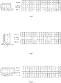
- the VRB bundles 0, 1, 2, 3, 4, 5, 6, 7, 8, 9, 10, 11 are mapped to the PRB bundles 0, 2, 4, 6, 8, 10, 1, 3, 5, 7, 9, 11 respectively, as shown in Fig. 2 .
- the size of the first and last RB bundles in the BWP may be smaller than the size L of the RB bundle notified by the network side.
- the technical solution provided by the embodiments of the present application is intended to solve the problem that the existing VRB-to-PRB mapping may cause the VRB bundle and the PRB bundle to be inconsistent in size so that the VRB-to-PRB mapping cannot be performed.
- the specific embodiments of the present application will be illustrated below in combination with the drawings.
- Fig. 4 is a schematic flow diagram of a resource mapping method, as shown, which includes:
- P is the number of rows or columns of the interleaver, including:
- the number of RB bundles in the BWP is N, and they are numbered as 0, 1, ..., N-1 in order from low to high frequency. Then, in the interleaved VRB-to-PRB mapping, the VRB bundle N-1 is fixedly mapped to the PRB bundle N-1; and the interleaved mapping is performed on the VRB bundle 0 to VRB bundle N-2 based on their bundle numbers to determine the corresponding PRB bundle numbers.
- FIG. 6 is a schematic diagram of the correspondence between indexes and bundle numbers of VRBs and PRBs in the first embodiment. As shown, it is assumed that the interleaved mapping from VRB bundles to PRB bundles follows the existing mapping method in the NR, then the VRB bundles 0, 1, 2, 3, 4, 5, 6, 7, 8, 9 are mapped to the PRB bundles 0, 2, 4, 6, 8, 1, 3, 5, 7, 9 respectively, as shown in Fig. 6 .
- the rows and columns of the interleaver are interchangeable.
- the number of columns of the interleaver is fixed to 2
- the number of rows is variable based on the BWP size and bundle size.
- the RB bundle numbers are written by row and read out by column.
- the interleaved mapping from VRB bundles to PRB bundles is not limited to the existing mapping method in the NR, because its essence is just the correspondence transformation between numbers.
- the technical solution provided by the embodiments of the present application does not limits the specific number correspondence rule, so the use of other methods will not affect the implementation of the embodiments of the present application.
- Fig. 7 is a schematic diagram of the correspondence between indexes and bundle numbers of VRBs and PRBs of the 4-row interleaver in the first embodiment. Then the VRB bundles 0, 1, 2, 3, 4, 5, 6, 7, 8, 9 are mapped to the PRB bundles 0, 4, 8, 1, 5, 9, 2, 6, 3, 7 respectively, as shown in Fig. 7 .
- FIG. 8 is a schematic diagram of the correspondence between indexes and bundle numbers of VRBs and PRBs of the 6-column interleaver in the first embodiment.
- the number C of the interleaver columns is increased to 6, and the VRB bundles 0, 1, 2, 3, 4, 5, 6, 7, 8, and 9 are mapped to the PRB bundles 0, 2, 4, 6, 8, 8, 9, 1, 3, 5, and 7 respectively, as shown in Fig. 8 .
- the number of RB bundles in the BWP is N, and they are numbered as 0, 1, ..., N-1 in order from low to high frequency.
- the interleaved VRB-to-PRB mapping the first M VRB bundles are fixedly and directly mapped to the PRB bundles with the same numbers as the VRB bundles; and the interleaved mapping is performed on the VRB bundle M to VRB bundle N-1 according to their bundle numbers to determine the corresponding PRB bundle numbers.
- M N ⁇ ⁇ N R ⁇ ⁇ R .
- Fig. 10 is a schematic diagram of the correspondence between indexes and bundle numbers of VRBs and PRBs in the second embodiment, and the details are as shown in Fig. 10 .
- N is the number of RB bundles in the BWP
- R is the number of rows of the interleaver
- C is the number of columns of the interleaver.
- inserting (C ⁇ R-N) nulls in the last row or last column of an interleaver includes: the inserted nulls do not occupy the last element position of the last row or last column of the interleaver.
- the inserting (C ⁇ R-N) nulls in the last row or last column of an interleaver includes:
- the number of RB bundles in the BWP is N, and they are numbered as 0, 1, ..., N-1 in order from low to high frequency.
- the number of rows of the interleaver is fixed to R, and the number C of columns of the interleaver is variable based on the BWP size and the bundle size (the rows and columns of the interleaver may be interchanged in the implementation).
- the VRB bundle numbers are written into the interleaver by column and read out by row.
- the first (C ⁇ R-N) rows in the last column of the interleaver are filled with nulls, and the positions filled with null are not written with VRB bundle numbers during writting and not read out from when the PRB bundle numbers are read out.
- Fig. 14 is a schematic diagram of the correspondence between indexes and bundle numbers of VRBs and PRBs when null is filled in the last column of the interleaver in the third embodiment, where the null filled in the last column of the interleaver may also be at another element position except the last row, as shown in Fig. 14 .
- the method may further include: determining the number of RB bundles in the BWP and/or whether the size of the last RB bundle is less than L, and determining whether to map the VRBs to the PRBs in units of RB bundle according to the judgment result, where L is the size of a RB bundle.
- the number of RB bundles in the BWP and/or whether the size of the last RB bundle is less than L is/are determined, and it is determined whether to apply the first, second or third embodiment according to the determining result.
- the determining the number of RB bundles in the BWP includes: determining whether the number of RB bundles in the BWP is an integer multiple of the number of interleaver rows or the number of interleaver columns.
- the determining whether the number of RB bundles in the BWP is an integer multiple of the number of interleaver rows or the number of interleaver columns includes:
- the embodiments of the present application further provide a computer device, a computer readable storage medium, and a resource mapping apparatus. Since the principle solving the problem of these devices is similar to the resource mapping method, the implementations of these devices may refer to the implementations of the method, and the repeated description thereof will be omitted here.
- a computer device provided in an embodiment of the present application includes a memory, a processor and a computer program that is stored on the memory and can run on the processor, where the processor, when executing the computer program, implements the following method:
- mapping the VRBs to PRBs in units of RB bundle includes:
- P is the number of rows or columns of the interleaver, including:
- mapping the VRBs to PRBs in units of RB bundle includes:
- the inserting (C ⁇ R-N) nulls in the last row or last column of an interleaver includes: the inserted nulls do not occupy the last element position of the last row or last column of the interleaver.
- the inserting (C ⁇ R-N) nulls in the last row or last column of an interleaver includes:
- the method before mapping the VRBs to the PRBs in units of RB bundle, the method further includes: determining the number of RB bundles in the BWP and/or whether the size of the last RB bundle is less than L, and determining whether to map the VRBs to the PRBs in units of RB bundle according to the determining result, where L is the size of a RB bundle.
- the determining the number of RB bundles in the BWP includes: determining whether the number of RB bundles in the BWP is an integer multiple of the number of interleaver rows or the number of interleaver columns.
- the determining whether the number of RB bundles in the BWP is an integer multiple of the number of interleaver rows or the number of interleaver columns includes:
- An embodiment of the present application provides a computer readable storage medium storing a computer program that performs the resource mapping method described above.
- the details may refer to the implementations of the computer device.
- the embodiments of the present application provides the mapping solution from the VRB bundle to the PRB bundle, which can avoid the problem that the VRB bundle and the PRB bundle are inconsistent in size so that the VRB-to-PRB mapping cannot be performed.
- the embodiments of the present application can provide methods, systems and computer program products.
- the present application can take the form of hardware embodiments alone, software embodiments alone, or embodiments combining the software and hardware aspects.
- the present application can take the form of computer program products implemented on one or more computer usable storage mediums (including but not limited to magnetic disk memories, CD-ROMs, optical memories and the like) containing computer usable program codes therein.
- These computer program instructions can also be stored in a computer readable memory which is capable of guiding the computer or another programmable data processing device to operate in a particular way, so that the instructions stored in the computer readable memory produce a manufacture including the instruction apparatus which implements the functions specified in one or more processes of the flow charts and/or one or more blocks of the block diagrams.
- These computer program instructions can also be loaded onto the computer or another programmable data processing device, so that a series of operation steps are performed on the computer or another programmable device to produce the computer-implemented processing.
- the instructions executed on the computer or another programmable device provide steps for implementing the functions specified in one or more processes of the flow charts and/or one or more blocks of the block diagrams.
Landscapes
- Engineering & Computer Science (AREA)
- Signal Processing (AREA)
- Computer Networks & Wireless Communication (AREA)
- Physics & Mathematics (AREA)
- Probability & Statistics with Applications (AREA)
- Theoretical Computer Science (AREA)
- Mathematical Physics (AREA)
- Error Detection And Correction (AREA)
- Mobile Radio Communication Systems (AREA)
- Stacking Of Articles And Auxiliary Devices (AREA)
- Detection And Prevention Of Errors In Transmission (AREA)
Abstract
Description
- The present application claims the priority from Chinese Patent Application No.
201810004885.0 - The present application relates to the field of wireless communication technologies and particularly to a resource mapping method, apparatus and device.
- In the NR (Next generation Radio) technology, the data to be sent that is carried by the data channel PDSCH (Physical Downlink Shared Channel)/PUSCH (Physical Uplink Shared Channel) is firstly mapped to a VRB (Virtual Resource Block), and then the VRB is mapped to a PRB (Physical Resource Block).
- There are two types of VRB-to-PRB mapping: interleaved mapping and non-interleaved mapping. The non-interleaved VRB-to-PRB mapping refers to that the VRB n is directly mapped to the PRB n. While for the interleaved VRB-to-PRB mapping, the unit is RB bundle (RB: Resource Block), and the VRB bundle j is mapped to the PRB bundle f(j).
- The deficiency of the prior art is that there are cases in which the mapping from VRB to PRB cannot be finished.
- The present application provides a resource mapping method and apparatus and device, so as to solve the problem that the existing VRB-to-PRB mapping may cause the VRB bundle and the PRB bundle to be inconsistent in size so that the VRB-to-PRB mapping cannot be performed.
- A resource mapping method provided in an embodiment of the present application includes:
- determining data to be sent that is carried on a data channel PDSCH/PUSCH;
- mapping the data to be sent to VRBs;
- mapping the VRBs to PRBs in units of RB bundle.
- Preferably, mapping the VRBs to the PRBs in units of RB bundle, includes:
- determining M VRB bundles with lower frequency and/or L VRB bundles with higher frequency in RBs occupied by the data channel;
- fixedly mapping the M VRB bundles with lower frequency and/or L VRB bundles with higher frequency to PRB bundles with same numbers as the VRB bundles;
- determining PRB bundle numbers corresponding to remaining VRB bundles through interleaved mapping.
- Preferably, the M VRB bundles with lower frequency include:
M = N - └N/P┘ × P, where N is the number of RB bundles in a Band Width Part (BWP), and P is the number of rows or columns of an interleaver. - Preferably, the L VRB bundles with higher frequency include:
L = N - └N/P┘ × P, where N is the number of RB bundles in a BWP, and P is the number of rows or columns of an interleaver. - Preferably, P is the number of rows or columns of the interleaver, including:
- if the number of rows of the interleaver is fixed, P is the number of rows of the interleaver;
- if the number of columns of the interleaver is fixed, P is the number of columns of the interleaver.
- Preferably, the L VRB bundles with higher frequency include a case that L = 1.
- Preferably, mapping the VRBs to the PRBs in units of RB bundle, includes:
- determining PRB bundle numbers corresponding to all VRB bundles through interleaved mapping;
- inserting (C∗R-N) nulls in a last row or last column of an interleaver, and ignoring nulls when reading out from the interleaver,
- where N is the number of RB bundles in a BWP, R is the number of rows of the interleaver, and C is the number of columns of the interleaver.
- Preferably, inserting (C∗R-N) nulls in a last row or last column of an interleaver, includes:
the inserted nulls do not occupy a last element position of the last row or last column of the interleaver. - Preferably, inserting (C∗R-N) nulls in a last row or last column of an interleaver, includes:
- if VRB bundle numbers are written into the interleaver by row and read out from the interleaver by column, then inserting (C∗R-N) nulls in the last row or last column of the interleaver by inserting (C∗R-N) nulls in the last row of the interleaver;
- if VRB bundle numbers are written into the interleaver by column and read out from the interleaver by row, then inserting (C∗R-N) nulls in the last row or last column of the interleaver by inserting (C∗R-N) nulls in the last column of the interleaver.
- Preferably, before mapping the VRB to the PRB in units of RB bundle, the method further includes:
determining the number of RB bundles in a BWP and/or whether the size of a last RB bundle is less than L, and determining whether to map the VRBs to the PRBs in units of RB bundle according to a determining result, where L is the size of a RB bundle. - Preferably, determining the number of RB bundles in a BWP, includes:
determining whether the number of RB bundles in the BWP is an integer multiple of the number of interleaver rows or the number of interleaver columns. - Preferably, determining whether the number of RB bundles in the BWP is an integer multiple of the number of interleaver rows or the number of interleaver columns, includes:
- if the number of interleaver rows is fixed, determining whether the number of RB bundles in the BWP is an integer multiple of the number of interleaver rows;
- if the number of interleaver columns is fixed, determining whether the number of RB bundles in the BWP is an integer multiple of the number of interleaver columns.
- A computer device provided in an embodiment of the present application includes a memory, a processor and a computer program that is stored on the memory and can run on the processor, where the processor, when executing the computer program, implements the following method:
- determining data to be sent that is carried on a data channel PDSCH/PUSCH;
- mapping the data to be sent to VRBs;
- mapping the VRBs to PRBs in units of RB bundle.
- In an implementation, mapping the VRBs to the PRBs in units of RB bundle, includes:
- determining M VRB bundles with lower frequency and/or L VRB bundles with higher frequency in RBs occupied by the data channel;
- fixedly mapping the M VRB bundles with lower frequency and/or L VRB bundles with higher frequency to PRB bundles with same numbers as the VRB bundles;
- determining PRB bundle numbers corresponding to remaining VRB bundles through interleaved mapping.
- Preferably, the M VRB bundles with lower frequency include:
M = N - └N/P┘ × P, where N is the number of RB bundles in a BWP, and P is the number of rows or columns of an interleaver. - Preferably, the L VRB bundles with higher frequency include:
L = N - └N/P┘ × P, where N is the number of RB bundles in a BWP, and P is the number of rows or columns of an interleaver. - Preferably, P is the number of rows or columns of the interleaver, including:
- if the number of rows of the interleaver is fixed, P is the number of rows of the interleaver;
- if the number of columns of the interleaver is fixed, P is the number of columns of the interleaver.
- Preferably, the L VRB bundles with higher frequency include a case that L = 1.
- Preferably, mapping the VRB to a PRB in units of RB bundle, includes:
- determining PRB bundle numbers corresponding to all VRB bundles through interleaved mapping;
- inserting (C∗R-N) nulls in a last row or last column of an interleaver, and ignoring nulls when reading out from the interleaver,
- where N is the number of RB bundles in a BWP, R is the number of rows of the interleaver, and C is the number of columns of the interleaver.
- Preferably, inserting (C∗R-N) nulls in a last row or last column of an interleaver, includes:
the inserted nulls do not occupy a last element position of the last row or last column of the interleaver. - Preferably, inserting (C∗R-N) nulls in a last row or last column of an interleaver, includes:
- if VRB bundle numbers are written into the interleaver by row and read out from the interleaver by column, then inserting (C∗R-N) nulls in the last row or last column of the interleaver by inserting (C∗R-N) nulls in the last row of the interleaver;
- if VRB bundle numbers are written into the interleaver by column and read out from the interleaver by row, then inserting (C∗R-N) nulls in the last row or last column of the interleaver by inserting (C∗R-N) nulls in the last column of the interleaver.
- Preferably, before mapping the VRBs to the PRBs in units of RB bundle, the method further includes:
determining the number of RB bundles in a BWP and/or whether the size of a last RB bundle is less than L, and determining whether to map the VRB to the PRB in units of RB bundle according to a determining result, where L is the size of a RB bundle. - Preferably, determining the number of RB bundles in a BWP, includes:
determining whether the number of RB bundles in the BWP is an integer multiple of the number of interleaver rows or the number of interleaver columns. - Preferably, determining whether the number of RB bundles in the BWP is an integer multiple of the number of interleaver rows or the number of interleaver columns, includes:
- if the number of interleaver rows is fixed, determining whether the number of RB bundles in the BWP is an integer multiple of the number of interleaver rows;
- if the number of interleaver columns is fixed, determining whether the number of RB bundles in the BWP is an integer multiple of the number of interleaver columns.
- An embodiment of the present application provides a computer readable storage medium storing a computer program that performs the resource mapping method described above.
- A resource mapping apparatus provided in an embodiment of the present application includes:
- a determining module configured to determine data to be sent that is carried on a data channel PDSCH/PUSCH;
- a mapping module configured to map the data to be sent to VRBs, and map the VRBs to PRBs in units of RB bundle.
- The present application has the following beneficial effects.
- The technical solution provided by the embodiments of the present application can avoid the problem that the VRB bundle and the PRB bundle are inconsistent in size so that the VRB-to-PRB mapping cannot be performed.
- The accompanying drawings illustrated here are used to provide the further understanding of the present application and constitute a part of the present application, and the schematic embodiments of the present application and the illustration thereof are used to explain the present application but not limit the present application improperly. In the accompanying drawings:
-
Fig. 1 is a schematic diagram illustrating the size correspondence of RB bundles in an embodiment of the present application; -
Fig. 2 is a schematic diagram of interleaved mapping of 12 RB bundles in an embodiment of the present application; -
Fig. 3 is a schematic diagram of inconsistent interleaved mapping of 11 RB bundles in an embodiment of the present application; -
Fig. 4 is a schematic flow diagram of a resource mapping method in an embodiment of the present application; -
Fig. 5 is a schematic diagram of the correspondence between RB indexes and RB bundle numbers in a first embodiment of the present application; -
Fig. 6 is a schematic diagram of the correspondence between indexes and bundle numbers of VRBs and PRBs in the first embodiment of the present application; -
Fig. 7 is a schematic diagram of the correspondence between indexes and bundle numbers of VRBs and PRBs of the 4-row interleaver in the first embodiment of the present application; -
Fig. 8 is a schematic diagram of the correspondence between indexes and bundle numbers of VRBs and PRBs of the 6-column interleaver in the first embodiment of the present application; -
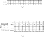
Fig. 9 is a schematic diagram of the correspondence between RB indexes and RB bundle numbers in a second embodiment of the present application; -
Fig. 10 is a schematic diagram of the correspondence between indexes and bundle numbers of VRBs and PRBs in the second embodiment of the present application; -
Fig. 11 is a schematic diagram of the correspondence between indexes and bundle numbers of VRBs and PRBs of the 4-row interleaver in the second embodiment of the present application; -
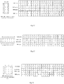
Fig. 12 is a schematic diagram of the correspondence between indexes and bundle numbers of VRBs and PRBs in a third embodiment of the present application; -
Fig. 13 is a schematic diagram of the correspondence between indexes and bundle numbers of VRBs and PRBs of the 4-row interleaver in the third embodiment of the present application; -
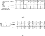
Fig. 14 is a schematic diagram of the correspondence between indexes and bundle numbers of VRBs and PRBs when nulls being filled in the last column of the interleaver in the third embodiment of the present application; -
Fig. 15 is a schematic diagram of the correspondence between indexes and bundle numbers of VRBs and PRBs with an integer multiple of RBG being satisfied in the third embodiment of the present application. - The inventor noticed the following in the inventive process.
- For the interleaved VRB-to-PRB mapping, the unit is RB bundle, and the size of the RB bundle is notified by the network side and is denoted as L during the process of mapping the VRB bundle j to the PRB bundle f(j). The size of the first RB bundle is


Fig. 1 is a schematic diagram of the correspondence of the sizes of RB bundles, where the correspondence between RB bundles and CRBs is as shown inFig. 1 . - The mapping from the VRB bundle j to the PRB bundle f(j) needs to satisfy:


- In the prior art, other methods are also used to express the interleaved mapping, e.g., the matrix method. Conversion is performed according to the predetermined rules or protocol requirements during the interleaved mapping. The embodiments of the present application will mainly take the above formula as an example to illustrate by way of a row-column interleaver.
- Specifically, for example, it is assumed that


Fig. 2 is a schematic diagram of the interleaved mapping of 12 RB bundles. As shown, there are 12 RB bundles in the BWP, and the number of interleaver columns is C = 6. The VRB bundle numbers are written into the 2-row and 6-column interleaver by column and then read out by row to realize the interleaved mapping from the VRB bundle numbers to the PRB bundle numbers. The VRB bundles 0, 1, 2, 3, 4, 5, 6, 7, 8, 9, 10, 11 are mapped to the PRB bundles 0, 2, 4, 6, 8, 10, 1, 3, 5, 7, 9, 11 respectively, as shown inFig. 2 . - In the prior art, due to the starting CRB number of the BWP, the size of the BWP, and the size of the RB bundle, the size of the first and last RB bundles in the BWP may be smaller than the size L of the RB bundle notified by the network side.
- When the size of the first RB bundle is less than L, the
VRB bundle 0 is fixedly mapping to thePRB bundle 0, so there will be no such problem that the size of the VRB bundle is inconsistent with the size of the PRB bundle. However, when the size of the last RB bundle is less than L, if the number of RB bundles in the BWP is an odd number, the situation where the VRB bundle is inconsistent with the PRB bundle in size may occur according to the existing VRB-to-PRB mapping rules.Fig. 3 is a schematic diagram illustrating the inconsistent interleaved mapping of 11 RB bundles. It needs to be noted that some parts are shown by bold line boxes and circles. As shown, it is assumed that
- Based on this, the technical solution provided by the embodiments of the present application is intended to solve the problem that the existing VRB-to-PRB mapping may cause the VRB bundle and the PRB bundle to be inconsistent in size so that the VRB-to-PRB mapping cannot be performed. The specific embodiments of the present application will be illustrated below in combination with the drawings.
-
Fig. 4 is a schematic flow diagram of a resource mapping method, as shown, which includes: - Step 401: determining the data to be sent that is carried on a data channel PDSCH/PUSCH. Here, the data channel is the PDSCH/PUSCH;
- Step 402: mapping the data to be sent to VRBs; and
- Step 403: mapping the VRBs to PRBs in units of RB bundle.
- The specific ways of mapping the VRBs to the PRBs in units of RB bundle will be illustrated below in combination with examples.
- 1. Mapping the VRBs to the PRBs in units of RB bundle, includes:
- determining M VRB bundles with lower frequency and/or L VRB bundles with higher frequency in the RBs occupied by the data channel;
- fixedly mapping the M VRB bundles with lower frequency and/or L VRB bundles with higher frequency to the PRB bundles with the same numbers as the VRB bundles;
- determining the PRB bundle numbers corresponding to the remaining VRB bundles through interleaved mapping.
- In an implementation, the M VRB bundles with lower frequency include:
M = N - └N/P┘ × P, where N is the number of RB bundles in the BWP, and P is the number of rows or columns of an interleaver. - In an implementation, the L VRB bundles with higher frequency include:
L = N - └N/P┘ × P, where N is the number of RB bundles in the BWP, and P is the number of rows or columns of an interleaver. - Further, in an implementation, P is the number of rows or columns of the interleaver, including:
- if the number of rows of the interleaver is fixed, P is the number of rows of the interleaver;
- if the number of columns of the interleaver is fixed, P is the number of columns of the interleaver.
- In an implementation, the L VRB bundles with higher frequency include a case that L = 1.
- In this embodiment, it is assumed that the number of RB bundles in the BWP is N, and they are numbered as 0, 1, ..., N-1 in order from low to high frequency. Then, in the interleaved VRB-to-PRB mapping, the VRB bundle N-1 is fixedly mapped to the PRB bundle N-1; and the interleaved mapping is performed on the
VRB bundle 0 to VRB bundle N-2 based on their bundle numbers to determine the corresponding PRB bundle numbers. - Specifically,
Fig. 5 is a schematic diagram of the correspondence between RB indexes and RB bundle numbers in the first embodiment. As shown, it is assumed that

Fig. 5 . Here there are 11 RB bundles, and theRB bundle 10 contains only one RB. - Then the
VRB bundle 10 is fixedly mapped to thePRB bundle 10, and the interleaved mapping is performed on theVRB bundle 0 toVRB bundle 9 according to their bundle numbers to determine the corresponding PRB bundle numbers.Fig. 6 is a schematic diagram of the correspondence between indexes and bundle numbers of VRBs and PRBs in the first embodiment. As shown, it is assumed that the interleaved mapping from VRB bundles to PRB bundles follows the existing mapping method in the NR, then the VRB bundles 0, 1, 2, 3, 4, 5, 6, 7, 8, 9 are mapped to the PRB bundles 0, 2, 4, 6, 8, 1, 3, 5, 7, 9 respectively, as shown inFig. 6 . - In an implementation, the rows and columns of the interleaver are interchangeable. For example, the number of columns of the interleaver is fixed to 2, and the number of rows is variable based on the BWP size and bundle size. Correspondingly, the RB bundle numbers are written by row and read out by column.
- In addition, the interleaved mapping from VRB bundles to PRB bundles is not limited to the existing mapping method in the NR, because its essence is just the correspondence transformation between numbers. The technical solution provided by the embodiments of the present application does not limits the specific number correspondence rule, so the use of other methods will not affect the implementation of the embodiments of the present application.
- For example, the number of rows of the above interleaver is increased to 4, and the number of columns is decreased accordingly. The above assumption is still followed.
Fig. 7 is a schematic diagram of the correspondence between indexes and bundle numbers of VRBs and PRBs of the 4-row interleaver in the first embodiment. Then the VRB bundles 0, 1, 2, 3, 4, 5, 6, 7, 8, 9 are mapped to the PRB bundles 0, 4, 8, 1, 5, 9, 2, 6, 3, 7 respectively, as shown inFig. 7 . - As another example, it is assumed that the number of RBs between the starting RB of the
VRB bundle 0 and the starting RB of theVRB bundle 1 in the interleaved mapping from VRB bundles to PRB bundles is required to be an integer multiple of RBG, that is, C∗L is an integer multiple of the RBG size, i.e.,
Fig. 8 is a schematic diagram of the correspondence between indexes and bundle numbers of VRBs and PRBs of the 6-column interleaver in the first embodiment. Then the number C of the interleaver columns is increased to 6, and the VRB bundles 0, 1, 2, 3, 4, 5, 6, 7, 8, and 9 are mapped to the PRB bundles 0, 2, 4, 6, 8, 8, 9, 1, 3, 5, and 7 respectively, as shown inFig. 8 . - In this embodiment, it is assumed that the number of RB bundles in the BWP is N, and they are numbered as 0, 1, ..., N-1 in order from low to high frequency. Then, in the interleaved VRB-to-PRB mapping, the first M VRB bundles are fixedly and directly mapped to the PRB bundles with the same numbers as the VRB bundles; and the interleaved mapping is performed on the VRB bundle M to VRB bundle N-1 according to their bundle numbers to determine the corresponding PRB bundle numbers.
- Assuming the number of interleaver rows is fixed to R, then

- Specifically,
Fig. 9 is a schematic diagram of the correspondence between RB indexes and RB bundle numbers in the second embodiment. As shown, the assumption of the first embodiment is still followed, where

Fig. 9 . - Assuming that an NR interleaver is used and the number of interleaver rows is fixed to R=2, then

VRB bundle 0 is fixedly mapped to thePRB bundle 0, and the interleaved mapping is performed on theVRB bundle 1 toVRB bundle 10 according to their bundle numbers to determine the corresponding PRB bundle numbers.Fig. 10 is a schematic diagram of the correspondence between indexes and bundle numbers of VRBs and PRBs in the second embodiment, and the details are as shown inFig. 10 . -
Fig. 11 is a schematic diagram of the correspondence between indexes and bundle numbers of VRBs and PRBs of the 4-row interleaver in the second embodiment. Assuming that the number of interleaver rows is R=4, then
VRB bundle 0 toVRB bundle 2 are fixedly mapped to thePRB bundle 0 toPRB bundle 2 respectively, and the interleaved mapping is used for theVRB bundle 3 toVRB bundle 10 to determine the corresponding PRB bundle numbers. The details are as shown inFig. 11 . - 2. Mapping the VRBs to the PRBs in units of RB bundle, includes:
- determining the PRB bundle numbers corresponding to all VRB bundles through interleaved mapping;
- inserting (C∗R-N) nulls in the last row or last column of an interleaver, and ignoring nulls when reading out from the interleaver.
- Here N is the number of RB bundles in the BWP, R is the number of rows of the interleaver, and C is the number of columns of the interleaver.
- In an implementation, inserting (C∗R-N) nulls in the last row or last column of an interleaver, includes:
the inserted nulls do not occupy the last element position of the last row or last column of the interleaver. - In an implementation, the inserting (C∗R-N) nulls in the last row or last column of an interleaver, includes:
- if the VRB bundle numbers are written into the interleaver by row and read out from the interleaver by column, then inserting (C∗R-N) nulls in the last row or last column of the interleaver by inserting (C∗R-N) nulls in the last row of the interleaver;
- if the VRB bundle numbers are written into the interleaver by column and read out from the interleaver by row, then inserting (C∗R-N) nulls in the last row or last column of the interleaver by inserting (C∗R-N) nulls in the last column of the interleaver.
- In this embodiment, it is assumed that the number of RB bundles in the BWP is N, and they are numbered as 0, 1, ..., N-1 in order from low to high frequency. The number of rows of the interleaver is fixed to R, and the number C of columns of the interleaver is variable based on the BWP size and the bundle size (the rows and columns of the interleaver may be interchanged in the implementation). The VRB bundle numbers are written into the interleaver by column and read out by row. The first (C∗R-N) rows in the last column of the interleaver are filled with nulls, and the positions filled with null are not written with VRB bundle numbers during writting and not read out from when the PRB bundle numbers are read out.
-
Fig. 12 is a schematic diagram of the correspondence between indexes and bundle numbers of VRBs and PRBs in the third embodiment. Assuming that an NR interleaver is used and the number of rows of the interleaver is R = 2, then the first 2∗6-11=1 row in the last column of the interleaver is filled with null, as shown inFig. 12 . -
Fig. 13 is a schematic diagram of the correspondence between indexes and bundle numbers of VRBs and PRBs of the 4-row interleaver in the third embodiment. Assuming that the number of rows of the interleaver is increased to R = 4, then the first 4∗3-11=1 row in the last column of the interleaver is filled with null, as shown inFig. 13 . -
Fig. 14 is a schematic diagram of the correspondence between indexes and bundle numbers of VRBs and PRBs when null is filled in the last column of the interleaver in the third embodiment, where the null filled in the last column of the interleaver may also be at another element position except the last row, as shown inFig. 14 . -
Fig. 15 is a schematic diagram of the correspondence between indexes and bundle numbers of VRBs and PRBs where integer multiple of RBG is satisfied in the third embodiment. Assuming that the number of RBs between the starting RB of theVRB bundle 0 and the starting RB of theVRB bundle 1 in the interleaved mapping from VRB bundles to PRB bundles is required to be an integer multiple of RBG, similarly to the first embodiment, then the first 2∗6-11=1 row in the last column of the interleaver is filled with null, as shown inFig. 15 . - In an implementation, before mapping the VRB to the PRB in units of RB bundle, the method may further include:
determining the number of RB bundles in the BWP and/or whether the size of the last RB bundle is less than L, and determining whether to map the VRBs to the PRBs in units of RB bundle according to the judgment result, where L is the size of a RB bundle. - The number of RB bundles in the BWP and/or whether the size of the last RB bundle is less than L is/are determined, and it is determined whether to apply the first, second or third embodiment according to the determining result.
- In an implementation, the determining the number of RB bundles in the BWP, includes:
determining whether the number of RB bundles in the BWP is an integer multiple of the number of interleaver rows or the number of interleaver columns. - In an implementation, the determining whether the number of RB bundles in the BWP is an integer multiple of the number of interleaver rows or the number of interleaver columns, includes:
- if the number of interleaver rows is fixed, determining whether the number of RB bundles in the BWP is an integer multiple of the number of interleaver rows;
- if the number of interleaver columns is fixed, determining whether the number of RB bundles in the BWP is an integer multiple of the number of interleaver columns.
- The specific implementation may be as follows.
- For example, it is determined whether the number of RB bundles in the BWP is an integer multiple of the number of interleaver rows or the number of interleaver columns. If it is not an integer multiple of the number of interleaver rows or the number of interleaver columns, the first, second or third embodiment is applied; otherwise, the interleaved mapping is performed on all the VRB bundles in the BWP according to their bundle numbers to determine the corresponding PRB bundle numbers, for example, using the existing mechanism.
- For example, it is determined whether the size of the last RB bundle is less than L. If it is less than L, the first, second or third embodiment is applied; otherwise, the interleaved mapping is performed on all the VRB bundles in the BWP according to their bundle numbers to determine the corresponding PRB bundle numbers, for example, using the existing mechanism.
- For example, the number of RB bundles in the BWP and whether the size of the last RB bundle is less than L are determined. If it is determined that the number of RB bundles in the BWP is not an integer multiple of the number of interleaver rows or the number of interleaver columns and the size of the last RB bundle is less than L, the first, second or third embodiment is applied; otherwise, the interleaved mapping is performed on all the VRB bundles in the BWP according to their bundle numbers to determine the corresponding PRB bundle numbers, for example, using the existing mechanism.
- Based upon the same inventive concept, the embodiments of the present application further provide a computer device, a computer readable storage medium, and a resource mapping apparatus. Since the principle solving the problem of these devices is similar to the resource mapping method, the implementations of these devices may refer to the implementations of the method, and the repeated description thereof will be omitted here.
- A computer device provided in an embodiment of the present application includes a memory, a processor and a computer program that is stored on the memory and can run on the processor, where the processor, when executing the computer program, implements the following method:
- determining the data to be sent that is carried on a data channel PDSCH/PUSCH;
- mapping the data to be sent to VRBs; and
- mapping the VRBs to PRBs in units of RB bundle.
- In an implementation, mapping the VRBs to PRBs in units of RB bundle, includes:
- determining M VRB bundles with lower frequency and/or L VRB bundles with higher frequency in the RBs occupied by the data channel;
- fixedly mapping the M VRB bundles with lower frequency and/or L VRB bundles with higher frequency to the PRB bundles with the same numbers as the VRB bundles; and
- determining the PRB bundle numbers corresponding to the remaining VRB bundles through interleaved mapping.
- In an implementation, the M VRB bundles with lower frequency include:
M = N - └N/P┘ × P, where N is the number of RB bundles in the BWP, and P is the number of rows or columns of an interleaver. - In an implementation, the L VRB bundles with higher frequency include:
L = N - └N/P┘× P, where N is the number of RB bundles in the BWP, and P is the number of rows or columns of an interleaver. - In an implementation, P is the number of rows or columns of the interleaver, including:
- if the number of rows of the interleaver is fixed, P is the number of rows of the interleaver;
- if the number of columns of the interleaver is fixed, P is the number of columns of the interleaver.
- In an implementation, the L VRB bundles with higher frequency include a case that L = 1.
- In an implementation, mapping the VRBs to PRBs in units of RB bundle, includes:
- determining the PRB bundle numbers corresponding to all VRB bundles through interleaved mapping; and
- inserting (C∗R-N) nulls in the last row or last column of an interleaver, and ignoring nulls when reading out from the interleaver;
- where N is the number of RB bundles in the BWP, R is the number of rows of the interleaver, and C is the number of columns of the interleaver.
- In an implementation, the inserting (C∗R-N) nulls in the last row or last column of an interleaver, includes:
the inserted nulls do not occupy the last element position of the last row or last column of the interleaver. - In an implementation, the inserting (C∗R-N) nulls in the last row or last column of an interleaver, includes:
- if the VRB bundle numbers are written into the interleaver by row and read out from the interleaver by column, then inserting (C∗R-N) nulls in the last row or last column of the interleaver by inserting (C∗R-N) nulls in the last row of the interleaver;
- if the VRB bundle numbers are written into the interleaver by column and read out from the interleaver by row, then inserting (C∗R-N) nulls in the last row or last column of the interleaver by inserting (C∗R-N) nulls in the last column of the interleaver.
- In an implementation, before mapping the VRBs to the PRBs in units of RB bundle, the method further includes:
determining the number of RB bundles in the BWP and/or whether the size of the last RB bundle is less than L, and determining whether to map the VRBs to the PRBs in units of RB bundle according to the determining result, where L is the size of a RB bundle. - In an implementation, the determining the number of RB bundles in the BWP, includes:
determining whether the number of RB bundles in the BWP is an integer multiple of the number of interleaver rows or the number of interleaver columns. - In an implementation, the determining whether the number of RB bundles in the BWP is an integer multiple of the number of interleaver rows or the number of interleaver columns, includes:
- if the number of interleaver rows is fixed, determining whether the number of RB bundles in the BWP is an integer multiple of the number of interleaver rows;
- if the number of interleaver columns is fixed, determining whether the number of RB bundles in the BWP is an integer multiple of the number of interleaver columns.
- An embodiment of the present application provides a computer readable storage medium storing a computer program that performs the resource mapping method described above. The details may refer to the implementations of the computer device.
- A resource mapping apparatus provided in an embodiment of the present application includes:
- a determining module configured to determine the data to be sent that is carried on a data channel PDSCH/PUSCH; and
- a mapping module configured to map the data to be sent to VRBs, and map the VRBs to PRBs in units of RB bundle.
- For the sake of description, all the parts of the above-mentioned device are divided into various modules or units by function, which are described respectively. Of course, the functions of the various modules or units may be implemented in the same one or more software or hardware when the present application is implemented.
- In summary, the embodiments of the present application provides the mapping solution from the VRB bundle to the PRB bundle, which can avoid the problem that the VRB bundle and the PRB bundle are inconsistent in size so that the VRB-to-PRB mapping cannot be performed.
- It should be understood by those skilled in the art that the embodiments of the present application can provide methods, systems and computer program products. Thus the present application can take the form of hardware embodiments alone, software embodiments alone, or embodiments combining the software and hardware aspects. Also the present application can take the form of computer program products implemented on one or more computer usable storage mediums (including but not limited to magnetic disk memories, CD-ROMs, optical memories and the like) containing computer usable program codes therein.
- The present application is described by reference to the flow charts and/or the block diagrams of the methods, the devices (systems) and the computer program products according to the embodiments of the present application. It should be understood that each process and/or block in the flow charts and/or the block diagrams, and a combination of processes and/or blocks in the flow charts and/or the block diagrams can be implemented by the computer program instructions. These computer program instructions can be provided to a general-purpose computer, a dedicated computer, an embedded processor, or a processor of another programmable data processing device to produce a machine, so that an apparatus for implementing the functions specified in one or more processes of the flow charts and/or one or more blocks of the block diagrams is produced by the instructions executed by the computer or the processor of another programmable data processing device.
- These computer program instructions can also be stored in a computer readable memory which is capable of guiding the computer or another programmable data processing device to operate in a particular way, so that the instructions stored in the computer readable memory produce a manufacture including the instruction apparatus which implements the functions specified in one or more processes of the flow charts and/or one or more blocks of the block diagrams.
- These computer program instructions can also be loaded onto the computer or another programmable data processing device, so that a series of operation steps are performed on the computer or another programmable device to produce the computer-implemented processing. Thus the instructions executed on the computer or another programmable device provide steps for implementing the functions specified in one or more processes of the flow charts and/or one or more blocks of the block diagrams.
- Although the preferred embodiments of the present application have been described, those skilled in the art can make additional alterations and modifications to these embodiments once they learn about the basic creative concepts. Thus the attached claims are intended to be interpreted to include the preferred embodiments as well as all the alterations and modifications falling within the scope of the present application.
- Evidently those skilled in the art can make various modifications and variations to the embodiments of the present application without departing from the spirit and scope of the embodiments of the present application. Thus the present application is also intended to encompass these modifications and variations therein as long as these modifications and variations to the embodiments of the present application come into the scope of the claims of the present application and their equivalents.
Claims (26)
- A resource mapping method, comprising:determining data to be sent that is carried on a data channel Physical Downlink Shared Channel, PDSCH/Physical Uplink Shared Channel, PUSCH;mapping the data to be sent to Virtual Resource Blocks, VRBs; andmapping the VRBs to Physical Resource Blocks, PRBs, in units of Resource Block, RB, bundle.
- The method of claim 1, wherein, said that mapping the VRBs to the PRBs in units of RB bundle, comprises:determining M VRB bundles with lower frequency and/or L VRB bundles with higher frequency in RBs occupied by the data channel;fixedly mapping the M VRB bundles with lower frequency and/or L VRB bundles with higher frequency to PRB bundles with same numbers as the VRB bundles; anddetermining PRB bundle numbers corresponding to remaining VRB bundles through interleaved mapping.
- The method of claim 2, wherein, the M VRB bundles with lower frequency comprise:
M = N - └N/P┘× P, wherein N is a quantity of RB bundles in a Band Width Part, BWP, and P is a quantity of rows or columns of an interleaver. - The method of claim 2, wherein, the L VRB bundles with higher frequency comprise:
L = N - └N/P┘× P, wherein N is a quantity of RB bundles in a Band Width Part, BWP, and P is a quantity of rows or columns of an interleaver. - The method of claim 3 or 4, wherein, P is the quantity of rows or columns of the interleaver, comprising:if the quantity of rows of the interleaver is fixed, P is the quantity of rows of the interleaver;if the quantity of columns of the interleaver is fixed, P is the quantity of columns of the interleaver.
- The method of claim 2, wherein, the L VRB bundles with higher frequency comprise a case that L = 1.
- The method of claim 1, wherein, said that mapping the VRB to a PRB in units of RB bundle, comprises:determining PRB bundle numbers corresponding to all VRB bundles through interleaved mapping; andinserting (C∗R-N) nulls in a last row or last column of an interleaver, and ignoring nulls when reading out from the interleaver,wherein N is a quantity of RB bundles in a BWP, R is a quantity of rows of the interleaver, and C is a quantity of columns of the interleaver.
- The method of claim 7, wherein, said that inserting (C∗R-N) nulls in a last row or last column of an interleaver, comprises:
inserted nulls do not occupy a last element position of the last row or last column of the interleaver. - The method of claim 7, wherein, said that inserting (C∗R-N) nulls in a last row or last column of an interleaver, comprises:if VRB bundle numbers are written into the interleaver by row and read out from the interleaver by column, then inserting (C∗R-N) nulls in the last row or last column of the interleaver by inserting (C∗R-N) nulls in the last row of the interleaver;if VRB bundle numbers are written into the interleaver by column and read out from the interleaver by row, then inserting (C∗R-N) nulls in the last row or last column of the interleaver by inserting (C∗R-N) nulls in the last column of the interleaver.
- The method of any one of claims 1 to 9, wherein, before said that mapping the VRBs to the PRBs in units of RB bundle, the method further comprises:
determining a quantity of RB bundles in a BWP and/or whether a size of a last RB bundle is less than L, and determining whether to map the VRBs to the PRBs in units of RB bundle according to a determining result, wherein L is a size of a RB bundle. - The method of claim 10, wherein, said that determining the quantity of RB bundles in a BWP, comprises:
determining whether the quantity of RB bundles in the BWP is an integer multiple of the quantity of interleaver rows or the quantity of interleaver columns. - The method of claim 11, wherein, said that determining whether the quantity of RB bundles in the BWP is an integer multiple of the quantity of interleaver rows or the quantity of interleaver columns, comprises:if the quantity of interleaver rows is fixed, determining whether the quantity of RB bundles in the BWP is an integer multiple of the quantity of interleaver rows;if the quantity of interleaver columns is fixed, determining whether the quantity of RB bundles in the BWP is an integer multiple of the quantity of interleaver columns.
- A computer device comprising a memory, a processor and a computer program that is stored on the memory and can run on the processor, wherein, the processor, when executing the computer program, implements a following method:determining data to be sent that is carried on a data channel PDSCH/PUSCH;mapping the data to be sent to VRBs; andmapping the VRBs to PRBs in units of RB bundle.
- The computer device of claim 13, wherein, said that mapping the VRBs to the PRBs in units of RB bundle, comprises:determining M VRB bundles with lower frequency and/or L VRB bundles with higher frequency in RBs occupied by the data channel;fixedly mapping the M VRB bundles with lower frequency and/or L VRB bundles with higher frequency to PRB bundles with same numbers as the VRB bundles; anddetermining PRB bundle numbers corresponding to remaining VRB bundles through interleaved mapping.
- The computer device of claim 14, wherein, the M VRB bundles with lower frequency comprise:
M = N - └N/P┘× P, wherein N is the quantity of RB bundles in a Band Width Part, BWP, and P is the quantity of rows or columns of an interleaver. - The computer device of claim 14, wherein, the L VRB bundles with higher frequency comprise:
L = N - └N/P┘× P, wherein N is the quantity of RB bundles in a Band Width Part, BWP, and P is the quantity of rows or columns of an interleaver. - The computer device of claim 15 or 16, wherein, P is the quantity of rows or columns of the interleaver, comprising:if the quantity of rows of the interleaver is fixed, P is the quantity of rows of the interleaver;if the quantity of columns of the interleaver is fixed, P is the quantity of columns of the interleaver.
- The computer device of claim 14, wherein, the L VRB bundles with higher frequency comprise a case that L = 1.
- The computer device of claim 13, wherein, said that mapping the VRBs to PRBs in units of RB bundle, comprises:determining PRB bundle numbers corresponding to all VRB bundles through interleaved mapping; andinserting (C∗R-N) nulls in a last row or last column of an interleaver, and ignoring nulls when reading out from the interleaver,wherein N is a quantity of RB bundles in a BWP, R is a quantity of rows of the interleaver, and C is a quantity of columns of the interleaver.
- The computer device of claim 19, wherein, said that inserting (C∗R-N) nulls in a last row or last column of an interleaver, comprises:
inserted nulls do not occupy a last element position of the last row or last column of the interleaver. - The computer device of claim 19, wherein, said that inserting (C∗R-N) nulls in a last row or last column of an interleaver, comprises:if VRB bundle numbers are written into the interleaver by row and read out from the interleaver by column, then inserting (C∗R-N) nulls in the last row or last column of the interleaver by inserting (C∗R-N) nulls in the last row of the interleaver;if VRB bundle numbers are written into the interleaver by column and read out from the interleaver by row, then inserting (C∗R-N) nulls in the last row or last column of the interleaver by inserting (C∗R-N) nulls in the last column of the interleaver.
- The computer device of any one of claims 13 to 21, wherein, before said that mapping the VRBs to the PRBs in units of RB bundle, the method further comprises:
determining a quantity of RB bundles in a BWP and/or whether a size of a last RB bundle is less than L, and determining whether to map the VRBs to the PRBs in units of RB bundle according to a determining result, wherein L is a size of a RB bundle. - The computer device of claim 22, wherein, said that determining the quantity of RB bundles in a BWP, comprises:
determining whether the quantity of RB bundles in the BWP is an integer multiple of the quantity of interleaver rows or the quantity of interleaver columns. - The computer device of claim 23, wherein, said that whether the quantity of RB bundles in the BWP is an integer multiple of the quantity of interleaver rows or the quantity of interleaver columns, comprises:if the quantity of interleaver rows is fixed, determining whether the quantity of RB bundles in the BWP is an integer multiple of the quantity of interleaver rows;if the quantity of interleaver columns is fixed, determining whether the quantity of RB bundles in the BWP is an integer multiple of the quantity of interleaver columns.
- A computer readable storage medium, wherein, the computer readable storage medium stores a computer program performing the method of any one of claims 1 to 12.
- A resource mapping apparatus, comprising:a determining module configured to determine data to be sent that is carried on a data channel PDSCH/PUSCH; anda mapping module configured to map the data to be sent to VRBs, and map the VRBs to PRBs in units of RB bundle.
Priority Applications (1)
| Application Number | Priority Date | Filing Date | Title |
|---|---|---|---|
| EP23159554.7A EP4213451A1 (en) | 2018-01-03 | 2018-12-12 | Resource mapping method and apparatus and device |
Applications Claiming Priority (2)
| Application Number | Priority Date | Filing Date | Title |
|---|---|---|---|
| CN201810004885.0A CN109995467B (en) | 2018-01-03 | 2018-01-03 | A resource mapping method, apparatus, and device |
| PCT/CN2018/120741 WO2019134487A1 (en) | 2018-01-03 | 2018-12-12 | Resource mapping method and apparatus and device |
Related Child Applications (2)
| Application Number | Title | Priority Date | Filing Date |
|---|---|---|---|
| EP23159554.7A Division-Into EP4213451A1 (en) | 2018-01-03 | 2018-12-12 | Resource mapping method and apparatus and device |
| EP23159554.7A Division EP4213451A1 (en) | 2018-01-03 | 2018-12-12 | Resource mapping method and apparatus and device |
Publications (3)
| Publication Number | Publication Date |
|---|---|
| EP3737053A1 true EP3737053A1 (en) | 2020-11-11 |
| EP3737053A4 EP3737053A4 (en) | 2021-03-03 |
| EP3737053B1 EP3737053B1 (en) | 2023-05-03 |
Family
ID=67128838
Family Applications (2)
| Application Number | Title | Priority Date | Filing Date |
|---|---|---|---|
| EP18898495.9A Active EP3737053B1 (en) | 2018-01-03 | 2018-12-12 | Resource mapping method and apparatus and device |
| EP23159554.7A Pending EP4213451A1 (en) | 2018-01-03 | 2018-12-12 | Resource mapping method and apparatus and device |
Family Applications After (1)
| Application Number | Title | Priority Date | Filing Date |
|---|---|---|---|
| EP23159554.7A Pending EP4213451A1 (en) | 2018-01-03 | 2018-12-12 | Resource mapping method and apparatus and device |
Country Status (7)
| Country | Link |
|---|---|
| US (2) | US11658779B2 (en) |
| EP (2) | EP3737053B1 (en) |
| JP (1) | JP7241760B2 (en) |
| KR (1) | KR102442930B1 (en) |
| CN (1) | CN109995467B (en) |
| TW (1) | TWI695599B (en) |
| WO (1) | WO2019134487A1 (en) |
Families Citing this family (8)
| Publication number | Priority date | Publication date | Assignee | Title |
|---|---|---|---|---|
| CN110035533B (en) * | 2018-01-12 | 2023-06-06 | 华为技术有限公司 | Resource mapping method and equipment |
| EP4156831B1 (en) * | 2018-12-21 | 2024-03-20 | LG Electronics, Inc. | Method for operating a user equipment in wireless communication system and user equipment supporting same |
| US11916671B2 (en) * | 2019-09-18 | 2024-02-27 | Qualcomm Incorporated | Methods for interleaved mapping |
| US20230135832A1 (en) * | 2020-05-05 | 2023-05-04 | Qualcomm Incorporated | Vrb-to-prb allocation for disjoint bwp segments |
| CN112153701B (en) * | 2020-09-09 | 2023-11-21 | 中国联合网络通信集团有限公司 | Method and device for determining bandwidth usage |
| CN114698110B (en) * | 2020-12-31 | 2026-02-17 | 维沃移动通信有限公司 | Resource mapping method, device and equipment |
| CN117240419A (en) * | 2022-06-02 | 2023-12-15 | 北京紫光展锐通信技术有限公司 | Communication method, device and storage medium |
| CN115997448A (en) * | 2022-10-14 | 2023-04-21 | 北京小米移动软件有限公司 | Method and device for determining frequency domain resources |
Family Cites Families (16)
| Publication number | Priority date | Publication date | Assignee | Title |
|---|---|---|---|---|
| JP3815344B2 (en) * | 2002-02-21 | 2006-08-30 | 株式会社日立製作所 | Codeword mapping method suitable for multilevel modulation |
| KR100904433B1 (en) * | 2008-01-07 | 2009-06-24 | 엘지전자 주식회사 | Distributed Virtual Resource Block Scheduling Method |
| KR100925441B1 (en) * | 2008-01-07 | 2009-11-06 | 엘지전자 주식회사 | Distributed Virtual Resource Block Scheduling Method |
| JP5247822B2 (en) * | 2008-12-18 | 2013-07-24 | 日本電信電話株式会社 | COMMUNICATION SYSTEM, TRANSMISSION DEVICE, RECEPTION DEVICE, TRANSMISSION METHOD, AND COMMUNICATION METHOD |
| JP2011151545A (en) | 2010-01-20 | 2011-08-04 | Nec Corp | Communication device, receiving method, and program |
| EP2561629A4 (en) | 2010-04-22 | 2014-11-05 | Lg Electronics Inc | Method and apparatus for channel estimation for radio link between a base station and a relay station |
| US9450729B2 (en) | 2011-06-15 | 2016-09-20 | Lg Electronics Inc. | Method and device for allocating a downlink control channel in a wireless communication system |
| IN2014CN03084A (en) | 2011-11-04 | 2015-07-03 | Intel Corp | |
| CN102412951B (en) * | 2011-11-17 | 2014-06-11 | 武汉邮电科学研究院 | Method and device for mapping distributed virtual resource blocks to physical resource blocks in LTE (Long Term Evolution) |
| WO2016114611A1 (en) | 2015-01-14 | 2016-07-21 | 엘지전자(주) | Method for updating area in wireless communication system, and device therefor |
| US10348448B2 (en) | 2015-01-22 | 2019-07-09 | Samsung Electronics Co., Ltd. | Transmitter and repetition method thereof |
| CN107925999B (en) * | 2015-08-31 | 2020-12-01 | 华为技术有限公司 | Resource allocation method and device |
| WO2017143529A1 (en) | 2016-02-24 | 2017-08-31 | 华为技术有限公司 | Signal transmission method and apparatus, and terminal device |
| CN108632915B (en) | 2017-03-20 | 2022-07-15 | 中兴通讯股份有限公司 | A method, device and device for terminal moving between 4G and 5G networks |
| EP3685623B1 (en) * | 2017-10-24 | 2021-08-11 | LG Electronics Inc. | Method and apparatus for performing random access procedure in wireless communication system |
| US12114291B2 (en) * | 2017-11-10 | 2024-10-08 | Qualcomm Incorporated | Virtual resource block to physical resource block mapping in new radio |
-
2018
- 2018-01-03 CN CN201810004885.0A patent/CN109995467B/en active Active
- 2018-12-12 EP EP18898495.9A patent/EP3737053B1/en active Active
- 2018-12-12 JP JP2020537192A patent/JP7241760B2/en active Active
- 2018-12-12 US US16/959,707 patent/US11658779B2/en active Active
- 2018-12-12 EP EP23159554.7A patent/EP4213451A1/en active Pending
- 2018-12-12 WO PCT/CN2018/120741 patent/WO2019134487A1/en not_active Ceased
- 2018-12-12 KR KR1020207022389A patent/KR102442930B1/en active Active
- 2018-12-18 TW TW107145610A patent/TWI695599B/en active
-
2022
- 2022-10-18 US US17/968,757 patent/US12238022B2/en active Active
Also Published As
| Publication number | Publication date |
|---|---|
| JP2021510037A (en) | 2021-04-08 |
| TWI695599B (en) | 2020-06-01 |
| EP3737053B1 (en) | 2023-05-03 |
| WO2019134487A1 (en) | 2019-07-11 |
| CN109995467B (en) | 2020-09-01 |
| US20230043981A1 (en) | 2023-02-09 |
| EP4213451A1 (en) | 2023-07-19 |
| US12238022B2 (en) | 2025-02-25 |
| CN109995467A (en) | 2019-07-09 |
| TW201931801A (en) | 2019-08-01 |
| US11658779B2 (en) | 2023-05-23 |
| US20200382249A1 (en) | 2020-12-03 |
| EP3737053A4 (en) | 2021-03-03 |
| JP7241760B2 (en) | 2023-03-17 |
| KR20200103815A (en) | 2020-09-02 |
| KR102442930B1 (en) | 2022-09-13 |
Similar Documents
| Publication | Publication Date | Title |
|---|---|---|
| US12238022B2 (en) | Resource mapping method and device | |
| US10631321B2 (en) | Method and apparatus for determining allocation of communication resources | |
| EP3952178A1 (en) | Resource determining and receiving methods and devices, electronic device, and storage medium | |
| US12107712B2 (en) | Method and apparatus for transmitting downlink control information | |
| US11470610B2 (en) | Resource mapping method and device | |
| CN101778394B (en) | Method and device for mapping resources | |
| EP3952536A1 (en) | Information sending method and apparatus | |
| US12490261B2 (en) | Scheduling method and apparatus, device and storage medium | |
| CN108809588B (en) | A kind of control channel resource mapping method and device | |
| US20180143787A1 (en) | Write method and write apparatus for storage device | |
| CN107566972A (en) | A kind of blue-teeth data high speed transmission method and device based on BLE standards | |
| US10140209B2 (en) | Time de-interleaving circuit and time de-interleaving method for reducing a number of times of accessing memory | |
| EP3706485A1 (en) | Method and device for determining reference signal, method and device for determining control channel unit, and storage medium | |
| US10164664B2 (en) | Time and cell de-interleaving circuit and method for performing time and cell de-interleaving | |
| RU2468512C2 (en) | Method for planning of distributed units of virtual resources | |
| CN106100790A (en) | A kind of data transmission method and system |
Legal Events
| Date | Code | Title | Description |
|---|---|---|---|
| STAA | Information on the status of an ep patent application or granted ep patent |
Free format text: STATUS: THE INTERNATIONAL PUBLICATION HAS BEEN MADE |
|
| PUAI | Public reference made under article 153(3) epc to a published international application that has entered the european phase |
Free format text: ORIGINAL CODE: 0009012 |
|
| STAA | Information on the status of an ep patent application or granted ep patent |
Free format text: STATUS: REQUEST FOR EXAMINATION WAS MADE |
|
| 17P | Request for examination filed |
Effective date: 20200723 |
|
| AK | Designated contracting states |
Kind code of ref document: A1 Designated state(s): AL AT BE BG CH CY CZ DE DK EE ES FI FR GB GR HR HU IE IS IT LI LT LU LV MC MK MT NL NO PL PT RO RS SE SI SK SM TR |
|
| AX | Request for extension of the european patent |
Extension state: BA ME |
|
| A4 | Supplementary search report drawn up and despatched |
Effective date: 20210129 |
|
| RIC1 | Information provided on ipc code assigned before grant |
Ipc: H04L 27/00 20060101AFI20210125BHEP Ipc: H03M 13/00 20060101ALI20210125BHEP Ipc: H04L 5/00 20060101ALI20210125BHEP Ipc: H03M 13/27 20060101ALI20210125BHEP Ipc: H04L 1/00 20060101ALI20210125BHEP |
|
| DAV | Request for validation of the european patent (deleted) | ||
| DAX | Request for extension of the european patent (deleted) | ||
| STAA | Information on the status of an ep patent application or granted ep patent |
Free format text: STATUS: EXAMINATION IS IN PROGRESS |
|
| RAP1 | Party data changed (applicant data changed or rights of an application transferred) |
Owner name: DATANG MOBILE COMMUNICATIONS EQUIPMENT CO., LTD. |
|
| 17Q | First examination report despatched |
Effective date: 20211007 |
|
| GRAP | Despatch of communication of intention to grant a patent |
Free format text: ORIGINAL CODE: EPIDOSNIGR1 |
|
| STAA | Information on the status of an ep patent application or granted ep patent |
Free format text: STATUS: GRANT OF PATENT IS INTENDED |
|
| INTG | Intention to grant announced |
Effective date: 20220525 |
|
| GRAJ | Information related to disapproval of communication of intention to grant by the applicant or resumption of examination proceedings by the epo deleted |
Free format text: ORIGINAL CODE: EPIDOSDIGR1 |
|
| STAA | Information on the status of an ep patent application or granted ep patent |
Free format text: STATUS: EXAMINATION IS IN PROGRESS |
|
| INTC | Intention to grant announced (deleted) | ||
| GRAP | Despatch of communication of intention to grant a patent |
Free format text: ORIGINAL CODE: EPIDOSNIGR1 |
|
| STAA | Information on the status of an ep patent application or granted ep patent |
Free format text: STATUS: GRANT OF PATENT IS INTENDED |
|
| INTG | Intention to grant announced |
Effective date: 20221125 |
|
| GRAS | Grant fee paid |
Free format text: ORIGINAL CODE: EPIDOSNIGR3 |
|
| GRAA | (expected) grant |
Free format text: ORIGINAL CODE: 0009210 |
|
| STAA | Information on the status of an ep patent application or granted ep patent |
Free format text: STATUS: THE PATENT HAS BEEN GRANTED |
|
| AK | Designated contracting states |
Kind code of ref document: B1 Designated state(s): AL AT BE BG CH CY CZ DE DK EE ES FI FR GB GR HR HU IE IS IT LI LT LU LV MC MK MT NL NO PL PT RO RS SE SI SK SM TR |
|
| REG | Reference to a national code |
Ref country code: GB Ref legal event code: FG4D |
|
| REG | Reference to a national code |
Ref country code: DE Ref legal event code: R096 Ref document number: 602018049417 Country of ref document: DE |
|
| REG | Reference to a national code |
Ref country code: AT Ref legal event code: REF Ref document number: 1565620 Country of ref document: AT Kind code of ref document: T Effective date: 20230515 Ref country code: CH Ref legal event code: EP |
|
| REG | Reference to a national code |
Ref country code: IE Ref legal event code: FG4D |
|
| P01 | Opt-out of the competence of the unified patent court (upc) registered |
Effective date: 20230512 |
|
| REG | Reference to a national code |
Ref country code: LT Ref legal event code: MG9D |
|
| REG | Reference to a national code |
Ref country code: NL Ref legal event code: MP Effective date: 20230503 |
|
| REG | Reference to a national code |
Ref country code: AT Ref legal event code: MK05 Ref document number: 1565620 Country of ref document: AT Kind code of ref document: T Effective date: 20230503 |
|
| PG25 | Lapsed in a contracting state [announced via postgrant information from national office to epo] |
Ref country code: SE Free format text: LAPSE BECAUSE OF FAILURE TO SUBMIT A TRANSLATION OF THE DESCRIPTION OR TO PAY THE FEE WITHIN THE PRESCRIBED TIME-LIMIT Effective date: 20230503 Ref country code: PT Free format text: LAPSE BECAUSE OF FAILURE TO SUBMIT A TRANSLATION OF THE DESCRIPTION OR TO PAY THE FEE WITHIN THE PRESCRIBED TIME-LIMIT Effective date: 20230904 Ref country code: NO Free format text: LAPSE BECAUSE OF FAILURE TO SUBMIT A TRANSLATION OF THE DESCRIPTION OR TO PAY THE FEE WITHIN THE PRESCRIBED TIME-LIMIT Effective date: 20230803 Ref country code: NL Free format text: LAPSE BECAUSE OF FAILURE TO SUBMIT A TRANSLATION OF THE DESCRIPTION OR TO PAY THE FEE WITHIN THE PRESCRIBED TIME-LIMIT Effective date: 20230503 Ref country code: ES Free format text: LAPSE BECAUSE OF FAILURE TO SUBMIT A TRANSLATION OF THE DESCRIPTION OR TO PAY THE FEE WITHIN THE PRESCRIBED TIME-LIMIT Effective date: 20230503 Ref country code: AT Free format text: LAPSE BECAUSE OF FAILURE TO SUBMIT A TRANSLATION OF THE DESCRIPTION OR TO PAY THE FEE WITHIN THE PRESCRIBED TIME-LIMIT Effective date: 20230503 |
|
| PG25 | Lapsed in a contracting state [announced via postgrant information from national office to epo] |
Ref country code: RS Free format text: LAPSE BECAUSE OF FAILURE TO SUBMIT A TRANSLATION OF THE DESCRIPTION OR TO PAY THE FEE WITHIN THE PRESCRIBED TIME-LIMIT Effective date: 20230503 Ref country code: PL Free format text: LAPSE BECAUSE OF FAILURE TO SUBMIT A TRANSLATION OF THE DESCRIPTION OR TO PAY THE FEE WITHIN THE PRESCRIBED TIME-LIMIT Effective date: 20230503 Ref country code: LV Free format text: LAPSE BECAUSE OF FAILURE TO SUBMIT A TRANSLATION OF THE DESCRIPTION OR TO PAY THE FEE WITHIN THE PRESCRIBED TIME-LIMIT Effective date: 20230503 Ref country code: LT Free format text: LAPSE BECAUSE OF FAILURE TO SUBMIT A TRANSLATION OF THE DESCRIPTION OR TO PAY THE FEE WITHIN THE PRESCRIBED TIME-LIMIT Effective date: 20230503 Ref country code: IS Free format text: LAPSE BECAUSE OF FAILURE TO SUBMIT A TRANSLATION OF THE DESCRIPTION OR TO PAY THE FEE WITHIN THE PRESCRIBED TIME-LIMIT Effective date: 20230903 Ref country code: HR Free format text: LAPSE BECAUSE OF FAILURE TO SUBMIT A TRANSLATION OF THE DESCRIPTION OR TO PAY THE FEE WITHIN THE PRESCRIBED TIME-LIMIT Effective date: 20230503 Ref country code: GR Free format text: LAPSE BECAUSE OF FAILURE TO SUBMIT A TRANSLATION OF THE DESCRIPTION OR TO PAY THE FEE WITHIN THE PRESCRIBED TIME-LIMIT Effective date: 20230804 |
|
| PG25 | Lapsed in a contracting state [announced via postgrant information from national office to epo] |
Ref country code: FI Free format text: LAPSE BECAUSE OF FAILURE TO SUBMIT A TRANSLATION OF THE DESCRIPTION OR TO PAY THE FEE WITHIN THE PRESCRIBED TIME-LIMIT Effective date: 20230503 |
|
| PG25 | Lapsed in a contracting state [announced via postgrant information from national office to epo] |
Ref country code: SK Free format text: LAPSE BECAUSE OF FAILURE TO SUBMIT A TRANSLATION OF THE DESCRIPTION OR TO PAY THE FEE WITHIN THE PRESCRIBED TIME-LIMIT Effective date: 20230503 |
|
| PG25 | Lapsed in a contracting state [announced via postgrant information from national office to epo] |
Ref country code: SM Free format text: LAPSE BECAUSE OF FAILURE TO SUBMIT A TRANSLATION OF THE DESCRIPTION OR TO PAY THE FEE WITHIN THE PRESCRIBED TIME-LIMIT Effective date: 20230503 Ref country code: SK Free format text: LAPSE BECAUSE OF FAILURE TO SUBMIT A TRANSLATION OF THE DESCRIPTION OR TO PAY THE FEE WITHIN THE PRESCRIBED TIME-LIMIT Effective date: 20230503 Ref country code: RO Free format text: LAPSE BECAUSE OF FAILURE TO SUBMIT A TRANSLATION OF THE DESCRIPTION OR TO PAY THE FEE WITHIN THE PRESCRIBED TIME-LIMIT Effective date: 20230503 Ref country code: EE Free format text: LAPSE BECAUSE OF FAILURE TO SUBMIT A TRANSLATION OF THE DESCRIPTION OR TO PAY THE FEE WITHIN THE PRESCRIBED TIME-LIMIT Effective date: 20230503 Ref country code: DK Free format text: LAPSE BECAUSE OF FAILURE TO SUBMIT A TRANSLATION OF THE DESCRIPTION OR TO PAY THE FEE WITHIN THE PRESCRIBED TIME-LIMIT Effective date: 20230503 Ref country code: CZ Free format text: LAPSE BECAUSE OF FAILURE TO SUBMIT A TRANSLATION OF THE DESCRIPTION OR TO PAY THE FEE WITHIN THE PRESCRIBED TIME-LIMIT Effective date: 20230503 |
|
| REG | Reference to a national code |
Ref country code: DE Ref legal event code: R097 Ref document number: 602018049417 Country of ref document: DE |
|
| PLBE | No opposition filed within time limit |
Free format text: ORIGINAL CODE: 0009261 |
|
| STAA | Information on the status of an ep patent application or granted ep patent |
Free format text: STATUS: NO OPPOSITION FILED WITHIN TIME LIMIT |
|
| 26N | No opposition filed |
Effective date: 20240206 |
|
| PG25 | Lapsed in a contracting state [announced via postgrant information from national office to epo] |
Ref country code: SI Free format text: LAPSE BECAUSE OF FAILURE TO SUBMIT A TRANSLATION OF THE DESCRIPTION OR TO PAY THE FEE WITHIN THE PRESCRIBED TIME-LIMIT Effective date: 20230503 |
|
| PG25 | Lapsed in a contracting state [announced via postgrant information from national office to epo] |
Ref country code: SI Free format text: LAPSE BECAUSE OF FAILURE TO SUBMIT A TRANSLATION OF THE DESCRIPTION OR TO PAY THE FEE WITHIN THE PRESCRIBED TIME-LIMIT Effective date: 20230503 Ref country code: IT Free format text: LAPSE BECAUSE OF FAILURE TO SUBMIT A TRANSLATION OF THE DESCRIPTION OR TO PAY THE FEE WITHIN THE PRESCRIBED TIME-LIMIT Effective date: 20230503 |
|
| REG | Reference to a national code |
Ref country code: CH Ref legal event code: PL |
|
| PG25 | Lapsed in a contracting state [announced via postgrant information from national office to epo] |
Ref country code: LU Free format text: LAPSE BECAUSE OF NON-PAYMENT OF DUE FEES Effective date: 20231212 |
|
| PG25 | Lapsed in a contracting state [announced via postgrant information from national office to epo] |
Ref country code: MC Free format text: LAPSE BECAUSE OF FAILURE TO SUBMIT A TRANSLATION OF THE DESCRIPTION OR TO PAY THE FEE WITHIN THE PRESCRIBED TIME-LIMIT Effective date: 20230503 |
|
| REG | Reference to a national code |
Ref country code: BE Ref legal event code: MM Effective date: 20231231 |
|
| PG25 | Lapsed in a contracting state [announced via postgrant information from national office to epo] |
Ref country code: MC Free format text: LAPSE BECAUSE OF FAILURE TO SUBMIT A TRANSLATION OF THE DESCRIPTION OR TO PAY THE FEE WITHIN THE PRESCRIBED TIME-LIMIT Effective date: 20230503 Ref country code: LU Free format text: LAPSE BECAUSE OF NON-PAYMENT OF DUE FEES Effective date: 20231212 |
|
| REG | Reference to a national code |
Ref country code: IE Ref legal event code: MM4A |
|
| PG25 | Lapsed in a contracting state [announced via postgrant information from national office to epo] |
Ref country code: IE Free format text: LAPSE BECAUSE OF NON-PAYMENT OF DUE FEES Effective date: 20231212 |
|
| PG25 | Lapsed in a contracting state [announced via postgrant information from national office to epo] |
Ref country code: BE Free format text: LAPSE BECAUSE OF NON-PAYMENT OF DUE FEES Effective date: 20231231 |
|
| PG25 | Lapsed in a contracting state [announced via postgrant information from national office to epo] |
Ref country code: CH Free format text: LAPSE BECAUSE OF NON-PAYMENT OF DUE FEES Effective date: 20231231 |
|
| PG25 | Lapsed in a contracting state [announced via postgrant information from national office to epo] |
Ref country code: IE Free format text: LAPSE BECAUSE OF NON-PAYMENT OF DUE FEES Effective date: 20231212 Ref country code: CH Free format text: LAPSE BECAUSE OF NON-PAYMENT OF DUE FEES Effective date: 20231231 Ref country code: BE Free format text: LAPSE BECAUSE OF NON-PAYMENT OF DUE FEES Effective date: 20231231 |
|
| PG25 | Lapsed in a contracting state [announced via postgrant information from national office to epo] |
Ref country code: BG Free format text: LAPSE BECAUSE OF FAILURE TO SUBMIT A TRANSLATION OF THE DESCRIPTION OR TO PAY THE FEE WITHIN THE PRESCRIBED TIME-LIMIT Effective date: 20230503 |
|
| PG25 | Lapsed in a contracting state [announced via postgrant information from national office to epo] |
Ref country code: BG Free format text: LAPSE BECAUSE OF FAILURE TO SUBMIT A TRANSLATION OF THE DESCRIPTION OR TO PAY THE FEE WITHIN THE PRESCRIBED TIME-LIMIT Effective date: 20230503 |
|
| PG25 | Lapsed in a contracting state [announced via postgrant information from national office to epo] |
Ref country code: CY Free format text: LAPSE BECAUSE OF FAILURE TO SUBMIT A TRANSLATION OF THE DESCRIPTION OR TO PAY THE FEE WITHIN THE PRESCRIBED TIME-LIMIT; INVALID AB INITIO Effective date: 20181212 |
|
| PG25 | Lapsed in a contracting state [announced via postgrant information from national office to epo] |
Ref country code: HU Free format text: LAPSE BECAUSE OF FAILURE TO SUBMIT A TRANSLATION OF THE DESCRIPTION OR TO PAY THE FEE WITHIN THE PRESCRIBED TIME-LIMIT; INVALID AB INITIO Effective date: 20181212 |
|
| PG25 | Lapsed in a contracting state [announced via postgrant information from national office to epo] |
Ref country code: TR Free format text: LAPSE BECAUSE OF FAILURE TO SUBMIT A TRANSLATION OF THE DESCRIPTION OR TO PAY THE FEE WITHIN THE PRESCRIBED TIME-LIMIT Effective date: 20230503 |
|
| PGFP | Annual fee paid to national office [announced via postgrant information from national office to epo] |
Ref country code: DE Payment date: 20251211 Year of fee payment: 8 |
|
| PGFP | Annual fee paid to national office [announced via postgrant information from national office to epo] |
Ref country code: GB Payment date: 20251219 Year of fee payment: 8 |
|
| PGFP | Annual fee paid to national office [announced via postgrant information from national office to epo] |
Ref country code: FR Payment date: 20251229 Year of fee payment: 8 |