EP3736936A1 - Determining model parameter values describing harmonic behavior of wind turbine generators - Google Patents
Determining model parameter values describing harmonic behavior of wind turbine generators Download PDFInfo
- Publication number
- EP3736936A1 EP3736936A1 EP19173711.3A EP19173711A EP3736936A1 EP 3736936 A1 EP3736936 A1 EP 3736936A1 EP 19173711 A EP19173711 A EP 19173711A EP 3736936 A1 EP3736936 A1 EP 3736936A1
- Authority
- EP
- European Patent Office
- Prior art keywords
- parameter value
- wea
- candidate
- source parameter
- impedance
- Prior art date
- Legal status (The legal status is an assumption and is not a legal conclusion. Google has not performed a legal analysis and makes no representation as to the accuracy of the status listed.)
- Ceased
Links
Images


Classifications
-
- H—ELECTRICITY
- H02—GENERATION; CONVERSION OR DISTRIBUTION OF ELECTRIC POWER
- H02J—ELECTRIC POWER NETWORKS; CIRCUIT ARRANGEMENTS OR SYSTEMS FOR SUPPLYING OR DISTRIBUTING ELECTRIC POWER; SYSTEMS FOR STORING ELECTRIC ENERGY
- H02J3/00—Circuit arrangements for AC mains or AC distribution networks
- H02J3/01—Arrangements for reducing harmonics or ripples
-
- H—ELECTRICITY
- H02—GENERATION; CONVERSION OR DISTRIBUTION OF ELECTRIC POWER
- H02J—ELECTRIC POWER NETWORKS; CIRCUIT ARRANGEMENTS OR SYSTEMS FOR SUPPLYING OR DISTRIBUTING ELECTRIC POWER; SYSTEMS FOR STORING ELECTRIC ENERGY
- H02J3/00—Circuit arrangements for AC mains or AC distribution networks
- H02J3/38—Arrangements for feeding a single network from two or more generators or sources in parallel; Arrangements for feeding already energised networks from additional generators or sources in parallel
- H02J3/381—Dispersed generators
-
- H—ELECTRICITY
- H02—GENERATION; CONVERSION OR DISTRIBUTION OF ELECTRIC POWER
- H02J—ELECTRIC POWER NETWORKS; CIRCUIT ARRANGEMENTS OR SYSTEMS FOR SUPPLYING OR DISTRIBUTING ELECTRIC POWER; SYSTEMS FOR STORING ELECTRIC ENERGY
- H02J2101/00—Supply or distribution of decentralised, dispersed or local electric power generation
- H02J2101/20—Dispersed power generation using renewable energy sources
- H02J2101/28—Wind energy
-
- H—ELECTRICITY
- H02—GENERATION; CONVERSION OR DISTRIBUTION OF ELECTRIC POWER
- H02J—ELECTRIC POWER NETWORKS; CIRCUIT ARRANGEMENTS OR SYSTEMS FOR SUPPLYING OR DISTRIBUTING ELECTRIC POWER; SYSTEMS FOR STORING ELECTRIC ENERGY
- H02J2103/00—Details of circuit arrangements for mains or AC distribution networks
- H02J2103/30—Simulating, planning, modelling, reliability check or computer assisted design [CAD] of electric power networks
-
- Y—GENERAL TAGGING OF NEW TECHNOLOGICAL DEVELOPMENTS; GENERAL TAGGING OF CROSS-SECTIONAL TECHNOLOGIES SPANNING OVER SEVERAL SECTIONS OF THE IPC; TECHNICAL SUBJECTS COVERED BY FORMER USPC CROSS-REFERENCE ART COLLECTIONS [XRACs] AND DIGESTS
- Y02—TECHNOLOGIES OR APPLICATIONS FOR MITIGATION OR ADAPTATION AGAINST CLIMATE CHANGE
- Y02E—REDUCTION OF GREENHOUSE GAS [GHG] EMISSIONS, RELATED TO ENERGY GENERATION, TRANSMISSION OR DISTRIBUTION
- Y02E10/00—Energy generation through renewable energy sources
- Y02E10/70—Wind energy
- Y02E10/76—Power conversion electric or electronic aspects
-
- Y—GENERAL TAGGING OF NEW TECHNOLOGICAL DEVELOPMENTS; GENERAL TAGGING OF CROSS-SECTIONAL TECHNOLOGIES SPANNING OVER SEVERAL SECTIONS OF THE IPC; TECHNICAL SUBJECTS COVERED BY FORMER USPC CROSS-REFERENCE ART COLLECTIONS [XRACs] AND DIGESTS
- Y02—TECHNOLOGIES OR APPLICATIONS FOR MITIGATION OR ADAPTATION AGAINST CLIMATE CHANGE
- Y02E—REDUCTION OF GREENHOUSE GAS [GHG] EMISSIONS, RELATED TO ENERGY GENERATION, TRANSMISSION OR DISTRIBUTION
- Y02E40/00—Technologies for an efficient electrical power generation, transmission or distribution
- Y02E40/40—Arrangements for reducing harmonics
-
- Y—GENERAL TAGGING OF NEW TECHNOLOGICAL DEVELOPMENTS; GENERAL TAGGING OF CROSS-SECTIONAL TECHNOLOGIES SPANNING OVER SEVERAL SECTIONS OF THE IPC; TECHNICAL SUBJECTS COVERED BY FORMER USPC CROSS-REFERENCE ART COLLECTIONS [XRACs] AND DIGESTS
- Y02—TECHNOLOGIES OR APPLICATIONS FOR MITIGATION OR ADAPTATION AGAINST CLIMATE CHANGE
- Y02E—REDUCTION OF GREENHOUSE GAS [GHG] EMISSIONS, RELATED TO ENERGY GENERATION, TRANSMISSION OR DISTRIBUTION
- Y02E60/00—Enabling technologies; Technologies with a potential or indirect contribution to GHG emissions mitigation
-
- Y—GENERAL TAGGING OF NEW TECHNOLOGICAL DEVELOPMENTS; GENERAL TAGGING OF CROSS-SECTIONAL TECHNOLOGIES SPANNING OVER SEVERAL SECTIONS OF THE IPC; TECHNICAL SUBJECTS COVERED BY FORMER USPC CROSS-REFERENCE ART COLLECTIONS [XRACs] AND DIGESTS
- Y04—INFORMATION OR COMMUNICATION TECHNOLOGIES HAVING AN IMPACT ON OTHER TECHNOLOGY AREAS
- Y04S—SYSTEMS INTEGRATING TECHNOLOGIES RELATED TO POWER NETWORK OPERATION, COMMUNICATION OR INFORMATION TECHNOLOGIES FOR IMPROVING THE ELECTRICAL POWER GENERATION, TRANSMISSION, DISTRIBUTION, MANAGEMENT OR USAGE, i.e. SMART GRIDS
- Y04S40/00—Systems for electrical power generation, transmission, distribution or end-user application management characterised by the use of communication or information technologies, or communication or information technology specific aspects supporting them
- Y04S40/20—Information technology specific aspects, e.g. CAD, simulation, modelling, system security
Definitions
- the present invention relates to the field of wind turbine generators, in particular to methods and systems for determining a source parameter value and an impedance parameter value for an electrical model of a wind turbine generator, wherein the electrical model is representative of a selected harmonic occurring during operation of the wind turbine generator.
- Harmonic oscillations in power grids i.e. oscillations at multiples of the grid frequency
- a method of determining a source parameter value and an impedance parameter value for an electrical model of a wind turbine generator wherein the electrical model is representative of a selected harmonic occurring during operation of the wind turbine generator.
- the method comprises (a) obtaining a set of measured voltage values and a set of measured current values corresponding to the selected harmonic, (b) calculating an initial source parameter value and an initial impedance parameter value based on the set of measured voltage values and the set of measured current values, (c) calculating a respective fitting index for each of a plurality of candidate combinations of respective candidate source parameter values and candidate impedance parameter values, wherein each candidate source parameter value is obtained as a multiple of the initial source parameter value divided by a first predetermined number and each candidate impedance parameter value is obtained as a multiple of the initial source parameter value divided by a second predetermined number, (d) selecting a subset of the candidate combinations for which the corresponding fitting index is maximal, and (e) determining the source parameter value and the impedance parameter
- This aspect of the invention is based on the idea that for a selected harmonic (such as 1*f, 2*f, 3*f, 4*f, 5*f and so on, where f denotes the grid frequency), a set of model parameter values (source parameter value and impedance parameter value) is determined, which describes the electrical behavior of the wind turbine generator with regard to the selected harmonic. This is done by obtaining measured voltage and current values corresponding to the selected harmonic (e.g. by applying DFT (Discrete Fourier Transform) or FFT (Fast Fourier Transform) to raw measurement data). Based on these sets of measurement data, initial parameter values are calculated and then a fitting index is calculated for each of a plurality of candidate combinations of candidate source parameter values and candidate impedance values.
- DFT Discrete Fourier Transform
- FFT Fast Fourier Transform
- the fitting index is indicative of how well a given candidate combination (and the corresponding electrical model) fits the measured reality.
- the candidate source parameter values are obtained as respective multiples of the initial source parameter values divided by a first predetermined number and the candidate impedance parameter values are obtained as respective multiples of the initial impedance parameter value divided by a second predetermined number.
- a matrix containing a fitting index for each candidate combination is formed.
- the subset of candidate combinations having the maximal fitting index is identified and the (final) source parameter value and the (final) impedance parameter value are determined based on this subset.
- the candidate combinations with the maximum fitting index are used to determined the desired parameter values (source parameter value and impedance parameter value) .
- the set of measured voltage values and the set of measured current values are obtained during operation of the wind turbine generator while it is connected to a power grid.
- the measurements are obtained during normal operation of the wind turbine generator while it is connected to the power grid.
- the measurements should be collected over a substantive period of time, such as during a week or more of continuous operation.
- the measurements are preferably obtained at a coupling point between the wind turbine generator and the power grid or at a point in the vicinity of this coupling point.
- the set of measured voltage values and the set of measured current values are obtained during operation of the wind turbine generator while it is connected to a power grid simulator.
- the grid simulator is capable of electrically behaving like a power grid in a wide range of situations. This can in particular be utilized to obtain a wider variation in the collected data in a significantly shorter period of time as compared to the above embodiment which relies on a true power grid.
- the power grid simulator is operated to generate a plurality of harmonics at a coupling point between the wind turbine generator and the power grid simulator.
- the electrical model is a Thevenin equivalent circuit
- the source parameter value is a Thevenin generator voltage
- the impedance parameter value is a Thevenin series impedance
- the electrical model consists of an ideal (alternating) voltage generator coupled in series with an impedance.
- the frequency of the voltage generator is a multiple of the grid frequency (e.g. 50 Hz, 100 Hz, 150 Hz, etc.).
- the initial source parameter value is calculated as a median value of the set of measured voltage values
- the initial impedance parameter value is calculated as the sum of all measured voltage values in the set of measured voltage values divided by the sum of all measured current values in the set of measured current values.
- the electrical model is a Norton equivalent circuit
- the source parameter value is a Norton generator current
- the impedance parameter value is a Norton parallel impedance
- the electrical model consists of an ideal (alternating) current generator coupled in parallel with an impedance.
- the frequency of the voltage generator is a multiple of the grid frequency (e.g. 50 Hz, 100 Hz, 150 Hz, etc.).
- the fitting index is indicative of how well the corresponding candidate combination fits the obtained sets of measured voltage values and measured current values.
- the fitting index may preferably be a number between 0 and 1, where a fitting index equal to 0 indicates no or a very bad fit while a fitting index equal to 1 indicates a perfect or very good fit.
- determining the source parameter value comprises (a) determining a minimum source parameter value and a maximum source parameter value in the selected subset of candidate combinations, and (b) determining the source parameter value as a mean value of the minimum source parameter value and the maximum source parameter value.
- determining the impedance parameter value comprises (a) determining a minimum impedance parameter value and a maximum impedance parameter value in the selected subset of candidate combinations, and (b) determining the impedance parameter value as a mean value of the minimum impedance parameter value and the maximum impedance parameter value.
- a system for determining a source parameter value and an impedance parameter value for an electrical model of a wind turbine generator wherein the electrical model is representative of a selected harmonic occurring during operation of the wind turbine generator.
- the system comprises (a) a measurement unit configured to obtain a set of measured voltage values and a set of measured current values corresponding to the selected harmonic, and (b) a processing unit configured to (b1) calculate an initial source parameter value and an initial impedance parameter value based on the set of measured voltage values and the set of measured current values, (b2) calculate a respective fitting index for each of a plurality of candidate combinations of respective candidate source parameter values and candidate impedance parameter values, wherein each candidate source parameter value is obtained as a multiple of the initial source parameter value divided by a first predetermined number and each candidate impedance parameter value is obtained as a multiple of the initial source parameter value divided by a second predetermined number, (b3) select a subset of the candidate combinations for which the corresponding fitting index is maximal, and (b
- This aspect of the invention is essentially based on the same idea as the first aspect described above.
- a computer program comprising computer executable instructions which, when executed by a computer processor, are adapted to cause the processor to perform the method according to the first aspect or any of the embodiments thereof.
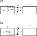
- FIG. 1 shows an electrical model 1 utilized in embodiments of the present invention.
- the electrical model 1 is a Thevenin equivalent circuit of a wind turbine generator and comprises a voltage generator in series with an impedance Z v,WEA .
- the wind turbine generator represented by the model 1 is coupled to a power grid 5 or a power grid simulator 6.
- a voltage U v,NAP and current I v,NAP corresponding to the v-th harmonic are measured, e.g. by applying FFT or DFT to corresponding raw measurement signals.
- Figure 2 shows another electrical model 2 utilized in embodiments of the present invention.
- the electrical model 2 is a Norton equivalent circuit of a wind turbine generator and comprises a current generator in parallel with an impedance Z v,WEA .
- the wind turbine generator represented by the model 2 is coupled to a power grid 5 or a power grid simulator 6.
- a voltage U v,NAP and current I v,NAP corresponding to the v-th harmonic are measured, e.g. by applying FFT or DFT to corresponding raw measurement signals.
- Figure 3 shows a flowchart of a method 300 according to an embodiment of the present invention, more specifically a method 300 of determining a source parameter value U v,WEA and an impedance parameter value Z v,WEA for an electrical model 1 (see Figure 1 ) of a wind turbine generator, wherein the electrical model is representative of a selected harmonic occurring during operation of the wind turbine generator.
- the method aims at determining the source parameter value U v,WEA and impedance parameter value Z v,WEA for a given v-th harmonic.
- the method 300 begins at 305 and continues at 310 with obtaining a set of measured voltage values U v,NAP (k) and a set of measured current values I v,NAP (k) corresponding to the selected harmonic.
- the index k has integer values between 1 and N tot .
- the measured values may be obtained over a longer period of time while the wind turbine generator is connected to a power grid 5 or during a (possibly) shorter period of time while the wind turbine generator is connected a power grid simulator 6. This will be discussed in more detail below in conjunction with Figures 7 and 8 .
- the obtained measurement values represent a variety of voltages and currents associated with the selected v-th harmonic of the grid frequency.
- an initial source parameter value U v,WEA,0 and an initial impedance parameter value Z v,WEA,0 based on the set of measured voltage values and the set of measured current values are calculated at 315.
- a fitting index r is calculated for the combination of candidate values U th and Z th .
- the fitting index is preferably a value between 0 (zero) and 1 (one), where a larger value indicates that the combination of candidate values fits the measurements better while a smaller value indicates that the combination of candidate values fits the measurements worse.
- the calculation of the fitting index r will be discussed in more detail below in conjunction with Figure 4 .
- the method returns to 325 and repeats the inner loop, i.e. steps 325, 330, 335, 340, and 345 for each incremented value of j and the corresponding new candidate impedance parameter value Z th calculated at 325.
- the method returns back to 320 and repeats the inner loop (i.e. steps 325, 330, 335, 340, and 345) for the corresponding new candidate source parameter value U th calculated at 320.
- both the first and second predetermined number is equal to 100.
- optimum values U v,WEA,opt and Z v,WEA,opt calculated by selecting a subset of the candidate combinations for which the corresponding fitting index r is maximal, and determining the source parameter value U v,WEA,opt and the impedance parameter value Z v,WEA,opt based on the selected subset of candidate combinations. More specifically, this is done by applying the algorithm 360A shown in Figure 5 and the algorithm 360B shown in Figure 6 to the matrix r mat as will be discussed in more detail further below.
- the method 300 continues to 365 where the optimum parameter values are output before the method ends at 370.
- Figure 4 shows a flowchart of a part of the method 300 shown in Figure 3 . More specifically, Figure 4 shows the calculating 330 of the fitting index r for a given candidate combination of U th and Z th .
- Figure 5 shows a flowchart of another part of the method 300 shown in Figure 3 . More specifically, Figure 5 shows the process 360A of calculating the optimum source parameter value U v,WEA,opt .
- Figure 6 shows a flowchart of yet another part of the method 300 shown in Figure 3 . More specifically, Figure 6 shows the process 360B of calculating the optimum impedance parameter value Z v,WEA,opt .
- the processes 360A and 360B are preferably performed in parallel.
- a subset of candidate combinations i.e. combinations of candidate source parameter values and impedance parameter values for which the corresponding fitting index is maximal is selected by going through the matrix r mat . Thereafter, the optimum source parameter value and the optimum impedance parameter value are determining based on the selected subset, in the present embodiment as the mean value of the maximum and minimum values in the subset.
- the corresponding method relies on measured voltage and current values corresponding to the selected harmonic.
- the quality of the determined parameter values evidently depends on the quality of the measurement data which can generally be obtained in one of two ways: either during normal operation of the wind turbine generator while it is connected to the power grid or during operation of the wind turbine generator while it is connected to a power grid simulator.
- measurements must be made during an extensive period of time in order to obtain data corresponding to a wide variety of operating conditions and power grid events.
- the diversity of the measurement data may be assured by corresponding programming of the power grid simulator such that the desired conditions and events are sufficiently represented. This takes much less time and generally leads to a more precise determination of the model parameters as shown in the following.
- Figure 7 shows a plot of measured harmonic voltages U v and currents I v in accordance with an embodiment of the present invention where the wind turbine generator is connected to a power grid simulator 6 (see Figure 1 and Figure 2 ).
- the measurement values 700 fit very well into a rectangle 701. Accordingly, there is a clear distinction between combinations of harmonic current and voltage that fit and do not fit the model (represented by the rectangle 701). This illustrates the point already made above, namely that a very precise model (source parameter value and impedance parameter value) can be obtained in this case.
- Figure 8 shows a plot of measured harmonic voltages U v and currents I v in accordance with another embodiment of the present invention where the wind turbine is connected to a power grid 5 (see Figure 1 and Figure 2 ) during normal operation.
- the obtained measurement values 800 cover a much smaller area in the graph and both rectangles 801 and 802 appear to surround them quite well.
Landscapes
- Engineering & Computer Science (AREA)
- Power Engineering (AREA)
- Control Of Eletrric Generators (AREA)
- Supply And Distribution Of Alternating Current (AREA)
Abstract
There is described a method of determining a source parameter value (U<sub>v,WEA</sub>, I<sub>v,WEA</sub>) and an impedance parameter value (Z<sub>v,WEA</sub>) for an electrical model (1, 2) of a wind turbine generator, wherein the electrical model is representative of a selected harmonic occurring during operation of the wind turbine generator. The method comprises obtaining (310) a set of measured voltage values (U<sub>v,NAP</sub>) and a set of measured current values (I<sub>v,NAP</sub>) corresponding to the selected harmonic, calculating (315) an initial source parameter value (U<sub>v,WEA,0</sub>) and an initial impedance parameter value (Z<sub>v,WEA,0</sub>) based on the set of measured voltage values and the set of measured current values, calculating (330) a respective fitting index (r) for each of a plurality of candidate combinations of respective candidate source parameter values and candidate impedance parameter values, wherein each candidate source parameter value is obtained as a multiple of the initial source parameter value divided by a first predetermined number and each candidate impedance parameter value is obtained as a multiple of the initial source parameter value divided by a second predetermined number, selecting a subset of the candidate combinations for which the corresponding fitting index is maximal, and determining (360) the source parameter value (U<sub>v,WEA,opt</sub>) and the impedance parameter value (Z<sub>v,WEA,opt</sub>) based on the selected subset of candidate combinations.
Description
- The present invention relates to the field of wind turbine generators, in particular to methods and systems for determining a source parameter value and an impedance parameter value for an electrical model of a wind turbine generator, wherein the electrical model is representative of a selected harmonic occurring during operation of the wind turbine generator.
- Harmonic oscillations in power grids, i.e. oscillations at multiples of the grid frequency, are a well-known problem. When connecting a wind turbine generator to a power grid, it is therefore desirable to know how the wind turbine generator may contribute and react to such oscillations.
- There may thus be a need for a simple and efficient way of obtaining useful information on the harmonic behavior of a wind turbine generator.
- This need may be met by the subject matter according to the independent claims. Advantageous embodiments of the present invention are described by the dependent claims.
- According to a first aspect of the invention there is provided a method of determining a source parameter value and an impedance parameter value for an electrical model of a wind turbine generator, wherein the electrical model is representative of a selected harmonic occurring during operation of the wind turbine generator. The method comprises (a) obtaining a set of measured voltage values and a set of measured current values corresponding to the selected harmonic, (b) calculating an initial source parameter value and an initial impedance parameter value based on the set of measured voltage values and the set of measured current values, (c) calculating a respective fitting index for each of a plurality of candidate combinations of respective candidate source parameter values and candidate impedance parameter values, wherein each candidate source parameter value is obtained as a multiple of the initial source parameter value divided by a first predetermined number and each candidate impedance parameter value is obtained as a multiple of the initial source parameter value divided by a second predetermined number, (d) selecting a subset of the candidate combinations for which the corresponding fitting index is maximal, and (e) determining the source parameter value and the impedance parameter value based on the selected subset of candidate combinations.
- This aspect of the invention is based on the idea that for a selected harmonic (such as 1*f, 2*f, 3*f, 4*f, 5*f and so on, where f denotes the grid frequency), a set of model parameter values (source parameter value and impedance parameter value) is determined, which describes the electrical behavior of the wind turbine generator with regard to the selected harmonic. This is done by obtaining measured voltage and current values corresponding to the selected harmonic (e.g. by applying DFT (Discrete Fourier Transform) or FFT (Fast Fourier Transform) to raw measurement data). Based on these sets of measurement data, initial parameter values are calculated and then a fitting index is calculated for each of a plurality of candidate combinations of candidate source parameter values and candidate impedance values. The fitting index is indicative of how well a given candidate combination (and the corresponding electrical model) fits the measured reality. The candidate source parameter values are obtained as respective multiples of the initial source parameter values divided by a first predetermined number and the candidate impedance parameter values are obtained as respective multiples of the initial impedance parameter value divided by a second predetermined number. In other words, a matrix containing a fitting index for each candidate combination is formed. Then, the subset of candidate combinations having the maximal fitting index is identified and the (final) source parameter value and the (final) impedance parameter value are determined based on this subset. Thus, the candidate combinations with the maximum fitting index are used to determined the desired parameter values (source parameter value and impedance parameter value) .
- According to an embodiment of the invention, the set of measured voltage values and the set of measured current values are obtained during operation of the wind turbine generator while it is connected to a power grid.
- In other words, the measurements are obtained during normal operation of the wind turbine generator while it is connected to the power grid. In order for the measurements to be representative of a wide variety of situations, the measurements should be collected over a substantive period of time, such as during a week or more of continuous operation.
- The measurements are preferably obtained at a coupling point between the wind turbine generator and the power grid or at a point in the vicinity of this coupling point.
- According to a further embodiment of the invention, the set of measured voltage values and the set of measured current values are obtained during operation of the wind turbine generator while it is connected to a power grid simulator.
- The grid simulator is capable of electrically behaving like a power grid in a wide range of situations. This can in particular be utilized to obtain a wider variation in the collected data in a significantly shorter period of time as compared to the above embodiment which relies on a true power grid. According to a further embodiment of the invention, the power grid simulator is operated to generate a plurality of harmonics at a coupling point between the wind turbine generator and the power grid simulator.
- Thereby, it can be assured that sufficient measurement data representative of each harmonic of interest is actually available.
- According to a further embodiment of the invention, the electrical model is a Thevenin equivalent circuit, the source parameter value is a Thevenin generator voltage, and the impedance parameter value is a Thevenin series impedance.
- In other words, the electrical model consists of an ideal (alternating) voltage generator coupled in series with an impedance. The frequency of the voltage generator is a multiple of the grid frequency (e.g. 50 Hz, 100 Hz, 150 Hz, etc.).
- According to a further embodiment of the invention, the initial source parameter value is calculated as a median value of the set of measured voltage values, and the initial impedance parameter value is calculated as the sum of all measured voltage values in the set of measured voltage values divided by the sum of all measured current values in the set of measured current values.
- According to a further embodiment of the invention, the electrical model is a Norton equivalent circuit, the source parameter value is a Norton generator current, and the impedance parameter value is a Norton parallel impedance.
- In other words, the electrical model consists of an ideal (alternating) current generator coupled in parallel with an impedance. The frequency of the voltage generator is a multiple of the grid frequency (e.g. 50 Hz, 100 Hz, 150 Hz, etc.). According to a further embodiment of the invention, the fitting index is indicative of how well the corresponding candidate combination fits the obtained sets of measured voltage values and measured current values.
- The fitting index may preferably be a number between 0 and 1, where a fitting index equal to 0 indicates no or a very bad fit while a fitting index equal to 1 indicates a perfect or very good fit.
- According to a further embodiment of the invention, determining the source parameter value comprises (a) determining a minimum source parameter value and a maximum source parameter value in the selected subset of candidate combinations, and (b) determining the source parameter value as a mean value of the minimum source parameter value and the maximum source parameter value.
- According to a further embodiment of the invention, determining the impedance parameter value comprises (a) determining a minimum impedance parameter value and a maximum impedance parameter value in the selected subset of candidate combinations, and (b) determining the impedance parameter value as a mean value of the minimum impedance parameter value and the maximum impedance parameter value.
- According to a second aspect of the invention there is provided a system for determining a source parameter value and an impedance parameter value for an electrical model of a wind turbine generator, wherein the electrical model is representative of a selected harmonic occurring during operation of the wind turbine generator. The system comprises (a) a measurement unit configured to obtain a set of measured voltage values and a set of measured current values corresponding to the selected harmonic, and (b) a processing unit configured to (b1) calculate an initial source parameter value and an initial impedance parameter value based on the set of measured voltage values and the set of measured current values, (b2) calculate a respective fitting index for each of a plurality of candidate combinations of respective candidate source parameter values and candidate impedance parameter values, wherein each candidate source parameter value is obtained as a multiple of the initial source parameter value divided by a first predetermined number and each candidate impedance parameter value is obtained as a multiple of the initial source parameter value divided by a second predetermined number, (b3) select a subset of the candidate combinations for which the corresponding fitting index is maximal, and (b4) determine the source parameter value and the impedance parameter value based on the selected subset of candidate combinations.
- This aspect of the invention is essentially based on the same idea as the first aspect described above.
- According to a third aspect of the invention, there is provided a computer program comprising computer executable instructions which, when executed by a computer processor, are adapted to cause the processor to perform the method according to the first aspect or any of the embodiments thereof.
- It is noted that embodiments of the invention have been described with reference to different subject matters. In particular, some embodiments have been described with reference to method type claims whereas other embodiments have been described with reference to apparatus type claims. However, a person skilled in the art will gather from the above and the following description that, unless otherwise indicated, in addition to any combination of features belonging to one type of subject matter also any combination of features relating to different subject matters, in particular to combinations of features of the method type claims and features of the apparatus type claims, is part of the disclosure of this document.
- The aspects defined above and further aspects of the present invention are apparent from the examples of embodiments to be described hereinafter and are explained with reference to the examples of embodiments. The invention will be described in more detail hereinafter with reference to examples of embodiments. However, it is explicitly noted that the invention is not limited to the described exemplary embodiments.
-
-
Figure 1 shows an electrical model utilized in embodiments of the present invention. -
Figure 2 shows another electrical model utilized in embodiments of the present invention. -
Figure 3 shows a flowchart of a method according to an embodiment of the present invention. -
Figure 4 shows a flowchart of a part of the method shown inFigure 3 . -
Figure 5 shows a flowchart of another part of the method shown inFigure 3 . -
Figure 6 shows a flowchart of yet another part of the method shown inFigure 3 . -
Figure 7 shows a plot of measured harmonic voltages and currents in accordance with an embodiment of the present invention. -
Figure 8 shows a plot of measured harmonic voltages and currents in accordance with another embodiment of the present invention. - The illustration in the drawing is schematic. It is noted that in different figures, similar or identical elements are provided with the same reference numerals or with reference numerals which differ only within the first digit.
-
Figure 1 shows anelectrical model 1 utilized in embodiments of the present invention. Theelectrical model 1 is a Thevenin equivalent circuit of a wind turbine generator and comprises a voltage generator in series with an impedance Zv,WEA. The voltage generator provides an alternating voltage with magnitude Uv,WEA and frequency corresponding to a selected v-th harmonic of a grid frequency (e.g. v∗50Hz, v = 1, 2, 3,...). The wind turbine generator represented by themodel 1 is coupled to a power grid 5 or a power grid simulator 6. At the point of interconnection between the wind turbine generator represented by themodel 1 and the power grid 5 or power grid simulator 6, a voltage Uv,NAP and current Iv,NAP corresponding to the v-th harmonic are measured, e.g. by applying FFT or DFT to corresponding raw measurement signals. -
Figure 2 shows anotherelectrical model 2 utilized in embodiments of the present invention. Theelectrical model 2 is a Norton equivalent circuit of a wind turbine generator and comprises a current generator in parallel with an impedance Zv,WEA. The current generator provides an alternating current with magnitude Iv,WEA and frequency corresponding to a selected v-th harmonic of a grid frequency (e.g. v∗50Hz, v = 1, 2, 3,...). Like inFigure 1 , the wind turbine generator represented by themodel 2 is coupled to a power grid 5 or a power grid simulator 6. At the point of interconnection between the wind turbine generator represented by themodel 2 and the power grid 5 or power grid simulator 6, a voltage Uv,NAP and current Iv,NAP corresponding to the v-th harmonic are measured, e.g. by applying FFT or DFT to corresponding raw measurement signals. -
Figure 3 shows a flowchart of amethod 300 according to an embodiment of the present invention, more specifically amethod 300 of determining a source parameter value Uv,WEA and an impedance parameter value Zv,WEA for an electrical model 1 (seeFigure 1 ) of a wind turbine generator, wherein the electrical model is representative of a selected harmonic occurring during operation of the wind turbine generator. In other words, the method aims at determining the source parameter value Uv,WEA and impedance parameter value Zv,WEA for a given v-th harmonic. - The
method 300 begins at 305 and continues at 310 with obtaining a set of measured voltage values Uv,NAP(k) and a set of measured current values Iv,NAP(k) corresponding to the selected harmonic. The index k has integer values between 1 and Ntot. The measured values may be obtained over a longer period of time while the wind turbine generator is connected to a power grid 5 or during a (possibly) shorter period of time while the wind turbine generator is connected a power grid simulator 6. This will be discussed in more detail below in conjunction withFigures 7 and 8 . In any event, the obtained measurement values represent a variety of voltages and currents associated with the selected v-th harmonic of the grid frequency. - Then, an initial source parameter value Uv,WEA,0 and an initial impedance parameter value Zv,WEA,0 based on the set of measured voltage values and the set of measured current values are calculated at 315. Here, a first index i is set to one, i.e. i = 1. The initial values are starting points for the algorithm and may in particular be calculated as follows:


- At 320, a candidate source parameter value Uth is calculated as

- At 325, a candidate impedance value Zth is calculated as

- Then, at 330 a fitting index r is calculated for the combination of candidate values Uth and Zth. The fitting index is preferably a value between 0 (zero) and 1 (one), where a larger value indicates that the combination of candidate values fits the measurements better while a smaller value indicates that the combination of candidate values fits the measurements worse. The calculation of the fitting index r will be discussed in more detail below in conjunction with
Figure 4 . - At 335, the calculated fitting index r is stored in a matrix rmat at a position corresponding to row i (i=1) and column j (j=1), and then j is incremented by one (j = j + 1) at 340.
- At 345, it is determined whether j > 600 and as long as this is not the case, the method returns to 325 and repeats the inner loop, i.e. steps 325, 330, 335, 340, and 345 for each incremented value of j and the corresponding new candidate impedance parameter value Zth calculated at 325.
- When it is determined at 345 that j > 600 (i.e. j = 601), the method continues to 350 where the first index i is incremented by one (i = i + 1).
- Then, at 355, it is determined whether i > 600 and as long as this is not the case, the method returns back to 320 and repeats the inner loop (i.e. steps 325, 330, 335, 340, and 345) for the corresponding new candidate source parameter value Uth calculated at 320.
- When it is determined at 355 that i > 600 (i.e. i = 601), the method continues to 360. At this stage, a 600 x 600 matrix rmat has been established by calculating a respective fitting index r for each of a plurality of candidate combinations of respective candidate source parameter values Uth and candidate impedance parameter values Zth, wherein each candidate source parameter value is obtained as a multiple of the initial source parameter value divided by a first predetermined number (i.e. Uth = U v,WEA,0 ▪ i/100) and each candidate impedance parameter value is obtained as a multiple of the initial source parameter value divided by a second predetermined number (i.e. Zth = Z v,WEA,0 ▪ j/100). Here, both the first and second predetermined number is equal to 100.
- At 360, optimum values Uv,WEA,opt and Zv,WEA,opt calculated by selecting a subset of the candidate combinations for which the corresponding fitting index r is maximal, and determining the source parameter value Uv,WEA,opt and the impedance parameter value Zv,WEA,opt based on the selected subset of candidate combinations. More specifically, this is done by applying the
algorithm 360A shown inFigure 5 and thealgorithm 360B shown inFigure 6 to the matrix rmat as will be discussed in more detail further below. - Having obtained the optimum parameter values Uv,WEA,opt and Zv,WEA,opt, the
method 300 continues to 365 where the optimum parameter values are output before the method ends at 370. -
Figure 4 shows a flowchart of a part of themethod 300 shown inFigure 3 . More specifically,Figure 4 shows the calculating 330 of the fitting index r for a given candidate combination of Uth and Zth. The calculatingprocess 330 begins at 405 where the measurement index k is set to one (k = 1) and the value rsum is set to zero (rsum = 0). Then, at 411, it is determined whether the k-th voltage measurement value Uv,NAP(k) is less than the candidate voltage value Uth, i.e. whether Uv,NAP(k) <Uth. If that is the case, the process continues to 416, otherwise it continues to 421. - At 416, it is determined whether

- If this is the case, the process continues to 426 where rsum is incremented by one (i.e. rsum = rsum + 1) and then to 431 where k is incremented by one (i.e. k = k + 1). If not, the process goes directly to 431 without incrementing rsum.
- Similarly at 421, it is determined whether

- Again, if this is the case, the process continues to 426 where rsum is incremented by one (i.e. rsum = rsum + 1) and then to 431 where k is incremented by one (i.e. k = k + 1). If not, the process goes directly to 431 without incrementing rsum.
- Thereafter, it is determined at 436 whether all measurement values have been used, i.e. whether k > Ntot. If this is not case, the process returns to 411 and repeats the
steps method 300 continues at 335 as discussed above in conjunction withFigure 3 . -
Figure 5 shows a flowchart of another part of themethod 300 shown inFigure 3 . More specifically,Figure 5 shows theprocess 360A of calculating the optimum source parameter value Uv,WEA,opt. The process begins at 507 where the index k is set to one (k = 1) and the value rmax is set to zero (rmax = 0). Then, at 512, the optimum fitting index r for the k-th row (i.e. in this case the first row) in the matrix rmat is found as
- Then, at 517, it is determined whether ropt(k) is larger than rmax, i.e. whether ropt(k) > rmax. If this is the case, the process continues to 522 where Umin is set equal to Uv,WEA,0 ∗k/100 and rmax is set equal to ropt(k) before the process continues to 532. Otherwise, the process continues to 527 where it is determined whether ropt(k) is equal to rmax. If this is the case, the process continues to 532 where Umax is set equal to Uv,WEA,0 ∗k/100. If not, 532 is skipped and the process continues at 537 by incrementing k by one (i.e. k = k + 1).
- Then, at 542, it is determined whether k exceeds 600, i.e. whether k > 600. If not, the process returns to 512 and repeats the
steps 
method 300 continues at 365 as discussed above in conjunction withFigure 3 . -
Figure 6 shows a flowchart of yet another part of themethod 300 shown inFigure 3 . More specifically,Figure 6 shows theprocess 360B of calculating the optimum impedance parameter value Zv,WEA,opt. The process begins at 608 where the index k is set to one (k = 1) and the value rmax is set to zero (rmax = 0). Then, at 613, the optimum fitting index r for the k-th column (i.e. in this case the first column) in the matrix rmat is found as
- Then, at 618, it is determined whether ropt(k) is larger than rmax, i.e. whether ropt(k) > rmax. If this is the case, the process continues to 623 where Zmin is set equal to Zv,WEA,0 ∗k/100 and rmax is set equal to ropt(k) before the process continues to 633. Otherwise, the process continues to 628 where it is determined whether ropt(k) is equal to rmax. If this is the case, the process continues to 633 where Zmax is set equal to Zv,MEA,0 ∗k/100. If not, 633 is skipped and the process continues at 638 by incrementing k by one (i.e. k = k + 1).
- Then, at 643, it is determined whether k exceeds 600, i.e. whether k > 600. If not, the process returns to 613 and repeats the
steps 
method 300 continues at 365 as discussed above in conjunction withFigure 3 . - The
processes - As can be seen from the above discussion of
Figure 5 andFigure 6 , a subset of candidate combinations (i.e. combinations of candidate source parameter values and impedance parameter values) for which the corresponding fitting index is maximal is selected by going through the matrix rmat. Thereafter, the optimum source parameter value and the optimum impedance parameter value are determining based on the selected subset, in the present embodiment as the mean value of the maximum and minimum values in the subset. - An important aspect of the present invention is that the corresponding method relies on measured voltage and current values corresponding to the selected harmonic. Thus, the quality of the determined parameter values evidently depends on the quality of the measurement data which can generally be obtained in one of two ways: either during normal operation of the wind turbine generator while it is connected to the power grid or during operation of the wind turbine generator while it is connected to a power grid simulator. In the first case, measurements must be made during an extensive period of time in order to obtain data corresponding to a wide variety of operating conditions and power grid events. In the second case, the diversity of the measurement data may be assured by corresponding programming of the power grid simulator such that the desired conditions and events are sufficiently represented. This takes much less time and generally leads to a more precise determination of the model parameters as shown in the following.
-
Figure 7 shows a plot of measured harmonic voltages Uv and currents Iv in accordance with an embodiment of the present invention where the wind turbine generator is connected to a power grid simulator 6 (seeFigure 1 and Figure 2 ). As can be seen, the measurement values 700 fit very well into arectangle 701. Accordingly, there is a clear distinction between combinations of harmonic current and voltage that fit and do not fit the model (represented by the rectangle 701). This illustrates the point already made above, namely that a very precise model (source parameter value and impedance parameter value) can be obtained in this case. - As a contrast,
Figure 8 shows a plot of measured harmonic voltages Uv and currents Iv in accordance with another embodiment of the present invention where the wind turbine is connected to a power grid 5 (seeFigure 1 and Figure 2 ) during normal operation. In this case, the obtainedmeasurement values 800 cover a much smaller area in the graph and bothrectangles Figure 7 . - It is noted that the term "comprising" does not exclude other elements or steps and the use of the articles "a" or "an" does not exclude a plurality. Also elements described in association with different embodiments may be combined. It is further noted that reference signs in the claims are not to be construed as limiting the scope of the claims.
Claims (12)
- A method of determining a source parameter value (Uv,WEA, Iv,WEA) and an impedance parameter value (Zv,WEA) for an electrical model (1, 2) of a wind turbine generator, wherein the electrical model is representative of a selected harmonic occurring during operation of the wind turbine generator, the method comprising
obtaining (310) a set of measured voltage values (Uv,NAP) and a set of measured current values (Iv,NAP) corresponding to the selected harmonic,
calculating (315) an initial source parameter value (Uv,WEA,0) and an initial impedance parameter value (Zv,WEA,0) based on the set of measured voltage values and the set of measured current values,
calculating (330) a respective fitting index (r) for each of a plurality of candidate combinations of respective candidate source parameter values and candidate impedance parameter values, wherein each candidate source parameter value is obtained as a multiple of the initial source parameter value divided by a first predetermined number and each candidate impedance parameter value is obtained as a multiple of the initial source parameter value divided by a second predetermined number,
selecting a subset of the candidate combinations for which the corresponding fitting index is maximal, and
determining (360) the source parameter value (Uv,WEA,opt) and the impedance parameter value (Zv,WEA,opt) based on the selected subset of candidate combinations. - The method according to the preceding claim, wherein the set of measured voltage values and the set of measured current values are obtained during operation of the wind turbine generator while it is connected to a power grid (5).
- The method according to claim 1, wherein the set of measured voltage values and the set of measured current values are obtained during operation of the wind turbine generator while it is connected to a power grid simulator (6).
- The method according to the preceding claim, wherein the power grid simulator is operated to generate a plurality of harmonics at a coupling point between the wind turbine generator and the power grid simulator.
- The method according to any of the preceding claims, wherein the electrical model is a Thevenin equivalent circuit (1), the source parameter value is a Thevenin generator voltage (Uv,MEA), and the impedance parameter value is a Thevenin series impedance (Zv,WEA).
- The method according to the preceding claim, wherein the initial source parameter value is calculated as a median value of the set of measured voltage values, and wherein the initial impedance parameter value is calculated as the sum of all measured voltage values in the set of measured voltage values divided by the sum of all measured current values in the set of measured current values.
- The method according to any of claims 1 to 4, wherein the electrical model is a Norton equivalent circuit (2), the source parameter value is a Norton generator current (Iv,WEA), and the impedance parameter value is a Norton parallel impedance (Zv,WEA).
- The method according to any of the preceding claims, wherein the fitting index is indicative of how well the corresponding candidate combination fits the obtained sets of measured voltage values and measured current values.
- The method according to any of the preceding claims, wherein determining the source parameter value comprises
determining a minimum source parameter value (Umin) and a maximum source parameter value (Umax) in the selected subset of candidate combinations, and
determining the source parameter value as a mean value of the minimum source parameter value and the maximum source parameter value. - The method according to any of the preceding claims, wherein determining the impedance parameter value comprises
determining a minimum impedance parameter value (Zmax) and a maximum impedance parameter value (Zmax) in the selected subset of candidate combinations, and
determining the impedance parameter value as a mean value of the minimum impedance parameter value and the maximum impedance parameter value. - A system for determining a source parameter value (Uv,WEA, Iv,WEA) and an impedance parameter value (Zv,WEA) for an electrical model (1, 2) of a wind turbine generator, wherein the electrical model is representative of a selected harmonic occurring during operation of the wind turbine generator, the system comprising
a measurement unit configured to obtain a set of measured voltage values (Uv,NAP) and a set of measured current values (Iv,NAP) corresponding to the selected harmonic, and
a processing unit configured to
calculate an initial source parameter value (Uv,WEA,0) and an initial impedance parameter value (Zv,WEA,0) based on the set of measured voltage values and the set of measured current values,
calculate a respective fitting index (r) for each of a plurality of candidate combinations of respective candidate source parameter values and candidate impedance parameter values, wherein each candidate source parameter value is obtained as a multiple of the initial source parameter value divided by a first predetermined number and each candidate impedance parameter value is obtained as a multiple of the initial source parameter value divided by a second predetermined number,
select a subset of the candidate combinations for which the corresponding fitting index is maximal, and
determine the source parameter value (Uv,WEA,opt) and the impedance parameter value (Zv,WEA,opt) based on the selected subset of candidate combinations. - A computer program comprising computer executable instructions which, when executed by a computer processor, are adapted to cause the processor to perform the method according to any of claims 1 to 10.
Priority Applications (5)
| Application Number | Priority Date | Filing Date | Title |
|---|---|---|---|
| EP19173711.3A EP3736936A1 (en) | 2019-05-10 | 2019-05-10 | Determining model parameter values describing harmonic behavior of wind turbine generators |
| ES20718233T ES3042833T3 (en) | 2019-05-10 | 2020-04-02 | Determining model parameter values describing harmonic behavior of wind turbine generators |
| DK20718233.8T DK3954013T3 (en) | 2019-05-10 | 2020-04-02 | Determining model parameter values describing harmonic behaviour of wind turbine generators |
| PCT/EP2020/059327 WO2020229048A1 (en) | 2019-05-10 | 2020-04-02 | Determining model parameter values describing harmonic behavior of wind turbine generators |
| EP20718233.8A EP3954013B1 (en) | 2019-05-10 | 2020-04-02 | Determining model parameter values describing harmonic behavior of wind turbine generators |
Applications Claiming Priority (1)
| Application Number | Priority Date | Filing Date | Title |
|---|---|---|---|
| EP19173711.3A EP3736936A1 (en) | 2019-05-10 | 2019-05-10 | Determining model parameter values describing harmonic behavior of wind turbine generators |
Publications (1)
| Publication Number | Publication Date |
|---|---|
| EP3736936A1 true EP3736936A1 (en) | 2020-11-11 |
Family
ID=66483871
Family Applications (2)
| Application Number | Title | Priority Date | Filing Date |
|---|---|---|---|
| EP19173711.3A Ceased EP3736936A1 (en) | 2019-05-10 | 2019-05-10 | Determining model parameter values describing harmonic behavior of wind turbine generators |
| EP20718233.8A Active EP3954013B1 (en) | 2019-05-10 | 2020-04-02 | Determining model parameter values describing harmonic behavior of wind turbine generators |
Family Applications After (1)
| Application Number | Title | Priority Date | Filing Date |
|---|---|---|---|
| EP20718233.8A Active EP3954013B1 (en) | 2019-05-10 | 2020-04-02 | Determining model parameter values describing harmonic behavior of wind turbine generators |
Country Status (4)
| Country | Link |
|---|---|
| EP (2) | EP3736936A1 (en) |
| DK (1) | DK3954013T3 (en) |
| ES (1) | ES3042833T3 (en) |
| WO (1) | WO2020229048A1 (en) |
Citations (3)
| Publication number | Priority date | Publication date | Assignee | Title |
|---|---|---|---|---|
| US6182017B1 (en) * | 1998-08-11 | 2001-01-30 | The Governor Of The University Of Alberta | Method and apparatus for differentiating contributions of harmonic pollution sources |
| EP3361272A1 (en) * | 2017-02-09 | 2018-08-15 | ABB Schweiz AG | Grid impedance estimation based on total least squares |
| CN109378855A (en) * | 2018-08-31 | 2019-02-22 | 上海电机学院 | A power grid simulator topology |
Family Cites Families (1)
| Publication number | Priority date | Publication date | Assignee | Title |
|---|---|---|---|---|
| CN104362628B (en) * | 2014-09-28 | 2016-05-25 | 浙江运达风电股份有限公司 | A control method and device for avoiding large-scale wind farm resonance |
-
2019
- 2019-05-10 EP EP19173711.3A patent/EP3736936A1/en not_active Ceased
-
2020
- 2020-04-02 ES ES20718233T patent/ES3042833T3/en active Active
- 2020-04-02 WO PCT/EP2020/059327 patent/WO2020229048A1/en not_active Ceased
- 2020-04-02 DK DK20718233.8T patent/DK3954013T3/en active
- 2020-04-02 EP EP20718233.8A patent/EP3954013B1/en active Active
Patent Citations (3)
| Publication number | Priority date | Publication date | Assignee | Title |
|---|---|---|---|---|
| US6182017B1 (en) * | 1998-08-11 | 2001-01-30 | The Governor Of The University Of Alberta | Method and apparatus for differentiating contributions of harmonic pollution sources |
| EP3361272A1 (en) * | 2017-02-09 | 2018-08-15 | ABB Schweiz AG | Grid impedance estimation based on total least squares |
| CN109378855A (en) * | 2018-08-31 | 2019-02-22 | 上海电机学院 | A power grid simulator topology |
Non-Patent Citations (3)
| Title |
|---|
| BABAK BADRZADEH ET AL: "Power system harmonic analysis in wind power plants Part I: Study methodology and techniques", INDUSTRY APPLICATIONS SOCIETY ANNUAL MEETING (IAS), 2012 IEEE, IEEE, 7 October 2012 (2012-10-07), pages 1 - 11, XP032278554, ISBN: 978-1-4673-0330-9, DOI: 10.1109/IAS.2012.6374102 * |
| BORKOWSKI DARIUSZ: "Power system impedance tracking using sliding, finite memory complex recursive least squares", 2013 SIGNAL PROCESSING: ALGORITHMS, ARCHITECTURES, ARRANGEMENTS, AND APPLICATIONS (SPA), POZNAN UNIV OF TECHNOLOGY, 26 September 2013 (2013-09-26), pages 78 - 81, XP032550275, ISSN: 2326-0262, ISBN: 978-83-62065-31-8, [retrieved on 20140113] * |
| MD. UMAR HASHMI ET AL: "Online Thevenin Equivalent Parameter Estimation using Nonlinear and Linear Recursive Least Square Algorithm", 20 July 2016 (2016-07-20), XP055330158, Retrieved from the Internet <URL:https://arxiv.org/ftp/arxiv/papers/1610/1610.05142.pdf> * |
Also Published As
| Publication number | Publication date |
|---|---|
| EP3954013B1 (en) | 2025-07-16 |
| DK3954013T3 (en) | 2025-10-13 |
| ES3042833T3 (en) | 2025-11-24 |
| EP3954013A1 (en) | 2022-02-16 |
| WO2020229048A1 (en) | 2020-11-19 |
Similar Documents
| Publication | Publication Date | Title |
|---|---|---|
| Kuwalek | Estimation of parameters associated with individual sources of voltage fluctuations | |
| US8680842B2 (en) | Method for measurement of total harmonic distortion | |
| Abdelrahman et al. | Practical approaches to assessment of harmonics along radial distribution feeders | |
| US20220182014A1 (en) | Characterization of electricity-producing cells using broadband impedance spectroscopy | |
| Mohammed et al. | Performance evaluation of wideband binary identification of grid impedance using grid-connected inverters | |
| CN113341223B (en) | Method suitable for power grid harmonic analysis and harmonic source positioning | |
| CN120638528A (en) | A photovoltaic grid-connected reactive power compensation method and system based on SVG | |
| EP3954013B1 (en) | Determining model parameter values describing harmonic behavior of wind turbine generators | |
| JP5953913B2 (en) | Generated power estimation device, generated power estimation method, and generated power estimation program | |
| CN107179758B (en) | A kind of dynamic signal parameter identification method and system | |
| CN119199403B (en) | A cable fault identification method, system, medium and device based on mutual inductor | |
| US8676524B2 (en) | System for computing machine parameters of an induction machine | |
| Domagk et al. | Identification of Equivalent Impedance Models of Downstream Networks for Harmonic Studies in Extra High Voltage Systems | |
| CN109088413B (en) | Dynamic reactive power planning and site selection method and device for direct-current receiving-end power grid | |
| Lahcène et al. | Detecting rotor faults of SCIG based wind turbine using PSD estimation methods | |
| RU2140089C1 (en) | Method of measurement of nonlinear distortions of four- terminal networks | |
| JP3620930B2 (en) | Power system characteristic estimation apparatus and characteristic estimation method | |
| CN114123164B (en) | Method and device for calculating short-circuit capacity of power system and terminal equipment | |
| CN110989363B (en) | Electric energy quality control method and device based on deep learning | |
| Gadanayak et al. | Microgrid protection using iterative filtering | |
| CN114240111A (en) | Power system risk operation assessment method and device and computer equipment | |
| CN120357496B (en) | A Method for Suppressing Wideband Oscillations in New Energy Grid Connection Based on Inverter Damping Control | |
| CN115313381B (en) | Voltage sag weak node monitoring method and device based on node load characteristics | |
| JP6921892B2 (en) | Output control device, power generation system, output control method, control program, and recording medium | |
| US20220175315A1 (en) | Method for estimating arrangement of electrodes on biological tissue |
Legal Events
| Date | Code | Title | Description |
|---|---|---|---|
| PUAI | Public reference made under article 153(3) epc to a published international application that has entered the european phase |
Free format text: ORIGINAL CODE: 0009012 |
|
| STAA | Information on the status of an ep patent application or granted ep patent |
Free format text: STATUS: THE APPLICATION HAS BEEN PUBLISHED |
|
| AK | Designated contracting states |
Kind code of ref document: A1 Designated state(s): AL AT BE BG CH CY CZ DE DK EE ES FI FR GB GR HR HU IE IS IT LI LT LU LV MC MK MT NL NO PL PT RO RS SE SI SK SM TR |
|
| AX | Request for extension of the european patent |
Extension state: BA ME |
|
| 18R | Application refused |
Effective date: 20201203 |