EP3736921A2 - Optical fiber laser device - Google Patents
Optical fiber laser device Download PDFInfo
- Publication number
- EP3736921A2 EP3736921A2 EP20172678.3A EP20172678A EP3736921A2 EP 3736921 A2 EP3736921 A2 EP 3736921A2 EP 20172678 A EP20172678 A EP 20172678A EP 3736921 A2 EP3736921 A2 EP 3736921A2
- Authority
- EP
- European Patent Office
- Prior art keywords
- rare earth
- doped
- core
- optical fiber
- fiber
- Prior art date
- Legal status (The legal status is an assumption and is not a legal conclusion. Google has not performed a legal analysis and makes no representation as to the accuracy of the status listed.)
- Granted
Links
Images








Classifications
-
- H—ELECTRICITY
- H01—ELECTRIC ELEMENTS
- H01S—DEVICES USING THE PROCESS OF LIGHT AMPLIFICATION BY STIMULATED EMISSION OF RADIATION [LASER] TO AMPLIFY OR GENERATE LIGHT; DEVICES USING STIMULATED EMISSION OF ELECTROMAGNETIC RADIATION IN WAVE RANGES OTHER THAN OPTICAL
- H01S3/00—Lasers, i.e. devices using stimulated emission of electromagnetic radiation in the infrared, visible or ultraviolet wave range
- H01S3/05—Construction or shape of optical resonators; Accommodation of active medium therein; Shape of active medium
- H01S3/06—Construction or shape of active medium
- H01S3/063—Waveguide lasers, i.e. whereby the dimensions of the waveguide are of the order of the light wavelength
- H01S3/067—Fibre lasers
-
- H—ELECTRICITY
- H01—ELECTRIC ELEMENTS
- H01S—DEVICES USING THE PROCESS OF LIGHT AMPLIFICATION BY STIMULATED EMISSION OF RADIATION [LASER] TO AMPLIFY OR GENERATE LIGHT; DEVICES USING STIMULATED EMISSION OF ELECTROMAGNETIC RADIATION IN WAVE RANGES OTHER THAN OPTICAL
- H01S3/00—Lasers, i.e. devices using stimulated emission of electromagnetic radiation in the infrared, visible or ultraviolet wave range
- H01S3/05—Construction or shape of optical resonators; Accommodation of active medium therein; Shape of active medium
- H01S3/06—Construction or shape of active medium
- H01S3/063—Waveguide lasers, i.e. whereby the dimensions of the waveguide are of the order of the light wavelength
- H01S3/067—Fibre lasers
- H01S3/06708—Constructional details of the fibre, e.g. compositions, cross-section, shape or tapering
- H01S3/06716—Fibre compositions or doping with active elements
-
- G—PHYSICS
- G02—OPTICS
- G02B—OPTICAL ELEMENTS, SYSTEMS OR APPARATUS
- G02B6/00—Light guides; Structural details of arrangements comprising light guides and other optical elements, e.g. couplings
- G02B6/0001—Light guides; Structural details of arrangements comprising light guides and other optical elements, e.g. couplings specially adapted for lighting devices or systems
- G02B6/0005—Light guides; Structural details of arrangements comprising light guides and other optical elements, e.g. couplings specially adapted for lighting devices or systems the light guides being of the fibre type
-
- G—PHYSICS
- G02—OPTICS
- G02B—OPTICAL ELEMENTS, SYSTEMS OR APPARATUS
- G02B6/00—Light guides; Structural details of arrangements comprising light guides and other optical elements, e.g. couplings
- G02B6/02—Optical fibres with cladding with or without a coating
- G02B6/02057—Optical fibres with cladding with or without a coating comprising gratings
- G02B6/02076—Refractive index modulation gratings, e.g. Bragg gratings
- G02B6/0208—Refractive index modulation gratings, e.g. Bragg gratings characterised by their structure, wavelength response
- G02B6/021—Refractive index modulation gratings, e.g. Bragg gratings characterised by their structure, wavelength response characterised by the core or cladding or coating, e.g. materials, radial refractive index profiles, cladding shape
-
- H—ELECTRICITY
- H01—ELECTRIC ELEMENTS
- H01S—DEVICES USING THE PROCESS OF LIGHT AMPLIFICATION BY STIMULATED EMISSION OF RADIATION [LASER] TO AMPLIFY OR GENERATE LIGHT; DEVICES USING STIMULATED EMISSION OF ELECTROMAGNETIC RADIATION IN WAVE RANGES OTHER THAN OPTICAL
- H01S3/00—Lasers, i.e. devices using stimulated emission of electromagnetic radiation in the infrared, visible or ultraviolet wave range
- H01S3/05—Construction or shape of optical resonators; Accommodation of active medium therein; Shape of active medium
- H01S3/06—Construction or shape of active medium
- H01S3/063—Waveguide lasers, i.e. whereby the dimensions of the waveguide are of the order of the light wavelength
- H01S3/067—Fibre lasers
- H01S3/06708—Constructional details of the fibre, e.g. compositions, cross-section, shape or tapering
- H01S3/0672—Non-uniform radial doping
-
- H—ELECTRICITY
- H01—ELECTRIC ELEMENTS
- H01S—DEVICES USING THE PROCESS OF LIGHT AMPLIFICATION BY STIMULATED EMISSION OF RADIATION [LASER] TO AMPLIFY OR GENERATE LIGHT; DEVICES USING STIMULATED EMISSION OF ELECTROMAGNETIC RADIATION IN WAVE RANGES OTHER THAN OPTICAL
- H01S3/00—Lasers, i.e. devices using stimulated emission of electromagnetic radiation in the infrared, visible or ultraviolet wave range
- H01S3/05—Construction or shape of optical resonators; Accommodation of active medium therein; Shape of active medium
- H01S3/06—Construction or shape of active medium
- H01S3/063—Waveguide lasers, i.e. whereby the dimensions of the waveguide are of the order of the light wavelength
- H01S3/067—Fibre lasers
- H01S3/06708—Constructional details of the fibre, e.g. compositions, cross-section, shape or tapering
- H01S3/06729—Peculiar transverse fibre profile
-
- H—ELECTRICITY
- H01—ELECTRIC ELEMENTS
- H01S—DEVICES USING THE PROCESS OF LIGHT AMPLIFICATION BY STIMULATED EMISSION OF RADIATION [LASER] TO AMPLIFY OR GENERATE LIGHT; DEVICES USING STIMULATED EMISSION OF ELECTROMAGNETIC RADIATION IN WAVE RANGES OTHER THAN OPTICAL
- H01S3/00—Lasers, i.e. devices using stimulated emission of electromagnetic radiation in the infrared, visible or ultraviolet wave range
- H01S3/05—Construction or shape of optical resonators; Accommodation of active medium therein; Shape of active medium
- H01S3/06—Construction or shape of active medium
- H01S3/063—Waveguide lasers, i.e. whereby the dimensions of the waveguide are of the order of the light wavelength
- H01S3/067—Fibre lasers
- H01S3/0675—Resonators including a grating structure, e.g. distributed Bragg reflectors [DBR] or distributed feedback [DFB] fibre lasers
-
- H—ELECTRICITY
- H01—ELECTRIC ELEMENTS
- H01S—DEVICES USING THE PROCESS OF LIGHT AMPLIFICATION BY STIMULATED EMISSION OF RADIATION [LASER] TO AMPLIFY OR GENERATE LIGHT; DEVICES USING STIMULATED EMISSION OF ELECTROMAGNETIC RADIATION IN WAVE RANGES OTHER THAN OPTICAL
- H01S3/00—Lasers, i.e. devices using stimulated emission of electromagnetic radiation in the infrared, visible or ultraviolet wave range
- H01S3/05—Construction or shape of optical resonators; Accommodation of active medium therein; Shape of active medium
- H01S3/06—Construction or shape of active medium
- H01S3/07—Construction or shape of active medium consisting of a plurality of parts, e.g. segments
-
- H—ELECTRICITY
- H01—ELECTRIC ELEMENTS
- H01S—DEVICES USING THE PROCESS OF LIGHT AMPLIFICATION BY STIMULATED EMISSION OF RADIATION [LASER] TO AMPLIFY OR GENERATE LIGHT; DEVICES USING STIMULATED EMISSION OF ELECTROMAGNETIC RADIATION IN WAVE RANGES OTHER THAN OPTICAL
- H01S3/00—Lasers, i.e. devices using stimulated emission of electromagnetic radiation in the infrared, visible or ultraviolet wave range
- H01S3/05—Construction or shape of optical resonators; Accommodation of active medium therein; Shape of active medium
- H01S3/08—Construction or shape of optical resonators or components thereof
- H01S3/08018—Mode suppression
- H01S3/0804—Transverse or lateral modes
- H01S3/08045—Single-mode emission
-
- H—ELECTRICITY
- H01—ELECTRIC ELEMENTS
- H01S—DEVICES USING THE PROCESS OF LIGHT AMPLIFICATION BY STIMULATED EMISSION OF RADIATION [LASER] TO AMPLIFY OR GENERATE LIGHT; DEVICES USING STIMULATED EMISSION OF ELECTROMAGNETIC RADIATION IN WAVE RANGES OTHER THAN OPTICAL
- H01S3/00—Lasers, i.e. devices using stimulated emission of electromagnetic radiation in the infrared, visible or ultraviolet wave range
- H01S3/14—Lasers, i.e. devices using stimulated emission of electromagnetic radiation in the infrared, visible or ultraviolet wave range characterised by the material used as the active medium
-
- H—ELECTRICITY
- H01—ELECTRIC ELEMENTS
- H01S—DEVICES USING THE PROCESS OF LIGHT AMPLIFICATION BY STIMULATED EMISSION OF RADIATION [LASER] TO AMPLIFY OR GENERATE LIGHT; DEVICES USING STIMULATED EMISSION OF ELECTROMAGNETIC RADIATION IN WAVE RANGES OTHER THAN OPTICAL
- H01S3/00—Lasers, i.e. devices using stimulated emission of electromagnetic radiation in the infrared, visible or ultraviolet wave range
- H01S3/14—Lasers, i.e. devices using stimulated emission of electromagnetic radiation in the infrared, visible or ultraviolet wave range characterised by the material used as the active medium
- H01S3/16—Solid materials
- H01S3/1691—Solid materials characterised by additives / sensitisers / promoters as further dopants
- H01S3/1698—Solid materials characterised by additives / sensitisers / promoters as further dopants rare earth
-
- H—ELECTRICITY
- H01—ELECTRIC ELEMENTS
- H01S—DEVICES USING THE PROCESS OF LIGHT AMPLIFICATION BY STIMULATED EMISSION OF RADIATION [LASER] TO AMPLIFY OR GENERATE LIGHT; DEVICES USING STIMULATED EMISSION OF ELECTROMAGNETIC RADIATION IN WAVE RANGES OTHER THAN OPTICAL
- H01S3/00—Lasers, i.e. devices using stimulated emission of electromagnetic radiation in the infrared, visible or ultraviolet wave range
- H01S3/05—Construction or shape of optical resonators; Accommodation of active medium therein; Shape of active medium
- H01S3/06—Construction or shape of active medium
- H01S3/063—Waveguide lasers, i.e. whereby the dimensions of the waveguide are of the order of the light wavelength
- H01S3/067—Fibre lasers
- H01S3/06754—Fibre amplifiers
-
- H—ELECTRICITY
- H01—ELECTRIC ELEMENTS
- H01S—DEVICES USING THE PROCESS OF LIGHT AMPLIFICATION BY STIMULATED EMISSION OF RADIATION [LASER] TO AMPLIFY OR GENERATE LIGHT; DEVICES USING STIMULATED EMISSION OF ELECTROMAGNETIC RADIATION IN WAVE RANGES OTHER THAN OPTICAL
- H01S3/00—Lasers, i.e. devices using stimulated emission of electromagnetic radiation in the infrared, visible or ultraviolet wave range
- H01S3/09—Processes or apparatus for excitation, e.g. pumping
- H01S3/091—Processes or apparatus for excitation, e.g. pumping using optical pumping
- H01S3/094—Processes or apparatus for excitation, e.g. pumping using optical pumping by coherent light
- H01S3/094003—Processes or apparatus for excitation, e.g. pumping using optical pumping by coherent light the pumped medium being a fibre
-
- H—ELECTRICITY
- H01—ELECTRIC ELEMENTS
- H01S—DEVICES USING THE PROCESS OF LIGHT AMPLIFICATION BY STIMULATED EMISSION OF RADIATION [LASER] TO AMPLIFY OR GENERATE LIGHT; DEVICES USING STIMULATED EMISSION OF ELECTROMAGNETIC RADIATION IN WAVE RANGES OTHER THAN OPTICAL
- H01S3/00—Lasers, i.e. devices using stimulated emission of electromagnetic radiation in the infrared, visible or ultraviolet wave range
- H01S3/09—Processes or apparatus for excitation, e.g. pumping
- H01S3/091—Processes or apparatus for excitation, e.g. pumping using optical pumping
- H01S3/094—Processes or apparatus for excitation, e.g. pumping using optical pumping by coherent light
- H01S3/0941—Processes or apparatus for excitation, e.g. pumping using optical pumping by coherent light of a laser diode
- H01S3/09415—Processes or apparatus for excitation, e.g. pumping using optical pumping by coherent light of a laser diode the pumping beam being parallel to the lasing mode of the pumped medium, e.g. end-pumping
-
- H—ELECTRICITY
- H01—ELECTRIC ELEMENTS
- H01S—DEVICES USING THE PROCESS OF LIGHT AMPLIFICATION BY STIMULATED EMISSION OF RADIATION [LASER] TO AMPLIFY OR GENERATE LIGHT; DEVICES USING STIMULATED EMISSION OF ELECTROMAGNETIC RADIATION IN WAVE RANGES OTHER THAN OPTICAL
- H01S3/00—Lasers, i.e. devices using stimulated emission of electromagnetic radiation in the infrared, visible or ultraviolet wave range
- H01S3/14—Lasers, i.e. devices using stimulated emission of electromagnetic radiation in the infrared, visible or ultraviolet wave range characterised by the material used as the active medium
- H01S3/16—Solid materials
- H01S3/1601—Solid materials characterised by an active (lasing) ion
- H01S3/1603—Solid materials characterised by an active (lasing) ion rare earth
- H01S3/1618—Solid materials characterised by an active (lasing) ion rare earth ytterbium
-
- H—ELECTRICITY
- H01—ELECTRIC ELEMENTS
- H01S—DEVICES USING THE PROCESS OF LIGHT AMPLIFICATION BY STIMULATED EMISSION OF RADIATION [LASER] TO AMPLIFY OR GENERATE LIGHT; DEVICES USING STIMULATED EMISSION OF ELECTROMAGNETIC RADIATION IN WAVE RANGES OTHER THAN OPTICAL
- H01S3/00—Lasers, i.e. devices using stimulated emission of electromagnetic radiation in the infrared, visible or ultraviolet wave range
- H01S3/14—Lasers, i.e. devices using stimulated emission of electromagnetic radiation in the infrared, visible or ultraviolet wave range characterised by the material used as the active medium
- H01S3/16—Solid materials
- H01S3/17—Solid materials amorphous, e.g. glass
- H01S3/176—Solid materials amorphous, e.g. glass silica or silicate glass
Definitions
- the invention relates to optical fiber laser devices.
- JP 2007-273600 A describes an optical fiber laser device that outputs laser light.
- optical fibers each having a fiber Bragg grating (FBG) are connected to both ends of a rare earth-doped fiber.
- FBG fiber Bragg grating
- a rare earth element is uniformly distributed in its entire core.
- the laser light is not single-mode (unimodal) laser light but multi-mode laser light with poor condensing properties.
- the invention relates to a technique for effectively outputting single-mode laser light as compared to the case where a rare earth element is uniformly distributed in the entire core.
- An optical fiber laser device includes: a first fiber having a first fiber Bragg grating; a second fiber having a second fiber Bragg grating with lower reflectance than the first fiber Bragg grating; and a third fiber doped with a rare earth element, having a first end connected with the first fiber, and having a second end connected with the second fiber.
- a central portion of a core of the third fiber is more heavily doped with the rare earth element than a peripheral portion of the core is.
- excitation light having entered the first fiber excites the rare earth element added to the core of the third fiber.
- the excited rare earth element thus spontaneously emits light with a specific wavelength.
- the spontaneously emitted light enters the second fiber and is reflected by the second fiber Bragg grating.
- the light reflected by the second fiber Bragg grating is amplified by the excited rare earth element as it travels back and forth between the first fiber Bragg grating and the second fiber Bragg grating.
- the amplified light having been amplified and thus having exceeded oscillation conditions passes through the second fiber Bragg grating and is output as laser light.
- the central portion of the core is more heavily doped with the rare earth element than the peripheral portion of the core is. Accordingly, the light passing through the central portion of the core is amplified as it travels back and forth between the first fiber Bragg grating and the second fiber Bragg grating a plurality of times. Single-mode laser light is thus output.
- the optical fiber laser device thus effectively outputs single-mode laser light as compared to the case where the rare earth element is uniformly distributed in the entire core.
- the central portion of the core may be doped with the rare earth element
- the peripheral portion of the core may not be doped with the rare earth element
- the following expression may be satisfied, where Da represents a diameter of the central portion doped with the rare earth element and Db represents a diameter of the core Db / 2 ⁇ Da ⁇ (3 ⁇ Db) / 4.
- the degree of amplification of an LP01 mode which is a single mode, is higher than in the case where the diameter Da of the doped portion is larger than (3 ⁇ Db) / 4 or smaller than Db / 2.
- the optical fiber laser device thus effectively outputs single-mode laser light.
- the peripheral portion of the core may include an absorbing portion that absorbs light in an output wavelength band.
- the gain of light that is output from the peripheral portion of the core is reduced as the peripheral portion of the core includes the absorbing portion that absorbs light in the output wavelength band.
- the optical fiber laser device thus effectively outputs single-mode laser light as compared to the case where the peripheral portion of the core does not include the absorbing portion that absorbs light in the output wavelength band.
- the rare earth element may be ytterbium, and the absorbing portion may be samarium-doped quartz.
- the optical fiber laser device effectively outputs single-mode laser light as compared to the case where the rare earth element is uniformly distributed in the entire core.
- FIGS. 1 to 10 An example of an optical fiber laser device according to a first embodiment of the invention will be described with reference to FIGS. 1 to 10 .
- Arrow H shown in the figures indicates the up-down direction of the device (vertical direction), and arrow W shown in the figures indicates the lateral direction of the vehicle (horizontal direction).
- an optical fiber laser device 10 includes an excitation light source 20 that outputs excitation light in a predetermined wavelength band, an optical fiber 30 with a first fiber Bragg grating 32 (hereinafter referred to as the "first FBG 32"), and a rare earth-doped fiber 50.
- the optical fiber laser device 10 further includes an optical fiber 80 with a second fiber Bragg grating 82 (hereinafter referred to as the "second FBG 82").
- the excitation light source 20, the optical fiber 30, the rare earth-doped fiber 50, and the optical fiber 80 are arranged in this order from one side to the other side in the lateral direction of the device.
- the optical fiber 30 is an example of the first fiber
- the optical fiber 80 is an example of the second fiber.
- the excitation light source 20 is, e.g., a semiconductor laser etc. As shown in FIG. 5 , the excitation light source 20 is disposed so as to face one end of the optical fiber 30. The excitation light source 20 outputs excitation light toward the one end of the optical fiber 30. In the present embodiment, the excitation light source 20 outputs, e.g., excitation light with a wavelength of 975 nm.
- the optical fiber 30 is linearly disposed such that its one end faces the excitation light source 20 and that the optical fiber 30 extends in the lateral direction of the device.
- the optical fiber 30 has its one end fused to the excitation light source 20.
- the optical fiber 30 has a core 34, a cladding 36 covering the core 34, and a resin cladding 38 covering the cladding 36.
- the refractive index of the cladding 36 is lower than that of the core 34, and the refractive index of the resin cladding 38 is significantly lower than that of the cladding 36.
- the core 34 is made of quartz doped with germanium, phosphorus, or aluminum, and the cladding 36 is made of quartz not doped with any dopant.
- the resin cladding 38 is made of an ultraviolet curable resin.
- the core 34 has a diameter of 40 ⁇ m
- the cladding 36 has a diameter of 400 ⁇ m
- the resin cladding 38 has a diameter of 800 ⁇ m.
- the first FBG 32 formed in the optical fiber 30 has a diffraction grating 40.
- the diffraction grating 40 has high refractive index portions 40a and low refractive index portions 40b in the core 34 of the optical fiber 30.
- the high refractive index portions 40a are arranged at regular intervals in the longitudinal direction of the optical fiber 30 and have a higher refractive index than the core 34.
- Each of the low refractive index portions 40b is located between a pair of high refractive index portions 40a and has the same refractive index as the core 34.
- the left-right direction in FIGS. 4A and 4B indicates the longitudinal direction of the fiber
- the up-down direction in FIGS. 4A and 4B indicates the radial direction of the fiber.
- the reflection center wavelength (Bragg wavelength) of light reflected by the first FBG 32 is, e.g., 1080 nm.
- the dimensions of each part, physical property values, etc. are determined so that the first FBG 32 reflects light with reflectance of 99% or more.
- the optical fiber 80 is linearly disposed so as to extend in the lateral direction of the device. As shown in FIG. 3A , the optical fiber 80 has a core 84, a cladding 86 covering the core 84, and a resin cladding 88 covering the cladding 86.
- Each member of the optical fiber 80 has a diameter similar to that of each member of the optical fiber 30 and is made of a material similar to that of each member of the optical fiber 30.
- the second FBG 82 formed in the optical fiber 80 has a diffraction grating 90.
- the diffraction grating 90 has high refractive index portions 90a and low refractive index portions 90b in the core 84 of the optical fiber 80.
- the high refractive index portions 90a are arranged at regular intervals in the longitudinal direction of the optical fiber 80 and have a higher refractive index than the core 84.
- Each of the low refractive index portions 90b is located between a pair of high refractive index portions 90a and has the same refractive index as the core 84.
- the reflection center wavelength (Bragg wavelength) of light reflected by the second FBG 82 is, e.g., 1080 nm like the first FBG 32.
- the reflectance of light reflected by the second FBG 82 is lower than that of light reflected by the first FBG 32.
- the dimensions of each part, physical property values, etc. are determined so that the second FBG 82 reflects light with reflectance of 10%.
- the rare earth-doped fiber 50 is disposed between the optical fiber 30 and the optical fiber 80 in the lateral direction of the device.
- the rare earth-doped fiber 50 is wound in a coil shape with a large diameter so that no stress is produced in the rare earth-doped fiber 50.
- the rare earth-doped fiber 50 has a core 54 doped with a rare earth element, a cladding 56 covering the core 54, and a resin cladding 58 covering the cladding 56.
- the refractive index of the cladding 56 is lower than that of the core 54, and the refractive index of the resin cladding 58 is significantly lower than that of the cladding 56.
- the core 54 is made of quartz doped with ytterbium (Yb) that is an example of the rare earth element, and the cladding 56 is made of quartz not doped with any dopant.
- the resin cladding 58 is made of an ultraviolet curable resin.
- the core 54 doped with the rare earth element will be described in detail later.
- the core 54 has a diameter of 40 ⁇ m
- the cladding 56 has a diameter of 400 ⁇ m
- the resin cladding 58 has a diameter of 500 ⁇ m.
- the rare earth-doped fiber 50 has a length of 9 m or more.
- the rare earth-doped fiber 50 has its one end fused to the other end of the optical fiber 30 by arc discharge machining (see FIG. 5 ). Specifically, the core 34 and the cladding 36 of the optical fiber 30 and the core 54 and the cladding 56 of the rare earth-doped fiber 50 are fused together by arc discharge (see FIGS. 3A and 3B ).
- the other end of the rare earth-doped fiber 50 is fused to one end of the optical fiber 80 by arc discharge machining (see FIG. 5 ). Specifically, the core 84 and the cladding 86 of the optical fiber 80 and the core 54 and the cladding 56 of the rare earth-doped fiber 50 are fused together by arc discharge (see FIGS. 3A and 3B ).
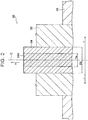
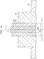
- FIG. 1 shows a section of the rare earth-doped fiber 50 taken in a direction perpendicular to the longitudinal direction of the rare earth-doped fiber 50.
- FIG. 2 is a refractive index distribution diagram showing distribution of the refractive index of the rare earth-doped fiber 50.
- the up-down direction in FIG. 2 indicates the level of the refractive index, and the greater the height in the figure is, the higher the refractive index is.
- the left-right direction in FIG. 2 indicates the radial direction of the rare earth-doped fiber 50.
- the dimensional ratios in the figures are exaggerated for convenience of description and may be different from the actual dimensional ratios.
- the core 54 of the rare earth-doped fiber 50 is made of quartz doped with the rare earth element and has a diameter of 40 ⁇ m.
- the central portion of the core 54 is doped with the rare earth element as viewed in the longitudinal direction of the rare earth-doped fiber 50, and a portion 54a doped with the rare earth element has a circular section.
- the doped portion 54a is shaded with dots in the figure.
- central portion of the core 54 herein refers to a portion that includes the center C of the core 54 and is located away from the cladding 56 as viewed in the longitudinal direction of the rare earth-doped fiber 50.
- the portion 54a doped with the rare earth element is a cylindrical portion concentric with the core 54 and having a predetermined diameter Da of 20 ⁇ m or more and 30 ⁇ m or less.
- the portion 54a doped with the rare earth element is a cylindrical portion with a predetermined diameter Da of Db / 2 or more and (3 ⁇ Db) / 4 or less, where Db represents the diameter of the core 54.
- the central portion of the core 54 is more heavily doped with the rare earth element than the peripheral portion of the core 54 is.
- the doped portion 54a is doped with the rare earth element at a predetermined concentration in the range of 0.5 mass% or more and 10 mass% or less.
- the concentration of the rare earth element is preferably high in order for the rare earth element to be excited and spontaneously emit light with a specific wavelength and is preferably low in order for the doped portion 54a to have a uniform concentration of the rare earth element.
- the doped portion 54a is therefore preferably doped with the rare earth element at the concentration of 1 mass% or more and 2 mass% or less.
- the portion 54a of the core 54 which is doped with the rare earth element can be specified by analysis using an electron probe micro analyzer (EPMA).
- EPMA electron probe micro analyzer
- optical fiber laser device 10 functions of the optical fiber laser device 10 will be described by comparison with an optical fiber laser device 510 according to a comparative form.
- the configuration of the optical fiber laser device 510 will be described mainly with respect to differences from the optical fiber laser device 10.
- functions of the optical fiber laser device 510 will also be described mainly with respect to differences from the optical fiber laser device 10.
- the optical fiber laser device 510 includes the excitation light source 20, the optical fiber 30, a rare earth-doped fiber 550, and the optical fiber 80.
- the rare earth-doped fiber 550 is disposed between the optical fiber 30 and the optical fiber 80 in the lateral direction of the device.
- the rare earth-doped fiber 550 is wound in a coil shape with a large diameter so that no stress is produced in the rare earth-doped fiber 550.
- the rare earth-doped fiber 550 has a core 554 doped with a rare earth element, the cladding 56 covering the core 554, and the resin cladding 58 covering the cladding 56.
- the core 554 is made of quartz doped with the rare earth element and has a diameter of 40 ⁇ m.
- the entire core 554 is uniformly doped with the rare earth element. In other words, the rare earth element is uniformly distributed in the entire core 554.
- the core 554 is doped with the rare earth element at the concentration of 0.5 mass% or more and 10 mass% or less.
- the rare earth-doped fibers 50, 550 were analyzed by simulation for the degree of amplification of each oscillation mode. This analysis will be described below.
- FIGS. 7A, 7B , 8A, and 8B are graphs in which the X-axis and the Y-axis are coordinate axes indicating the position in a section of the core and the Z-axis represents radiant intensity.
- the LP01 mode is a single mode (unimodal) in which the output is the highest at the center of the core and an extreme value, namely the output higher than at surrounding locations, appears at one location.
- the LP02 mode is a multi-mode in which the output is the highest at the center of the core and extreme values, namely the output higher than at surrounding locations, appear in a circle pattern around the center of the core.
- the LP03 mode is a multi-mode in which the output is the highest at the center of the core and extreme values, namely the output higher than at surrounding locations, appear in a double-circle pattern around the center of the core.
- the LP04 mode is a multi-mode in which the output is the highest at the center of the core and extreme values, namely the output higher than at surrounding locations, appear in a triple-circle pattern around the center of the core.
- FIG. 6 is a graph in which the abscissa represents the oscillation mode and the ordinate represents the degree of amplification of the oscillation mode (hereinafter sometimes simply referred to as the "degree of amplification").
- the continuous line in the graph indicates the analysis results of Example 1
- the long dashed short dashed line in the graph indicates the analysis results of Example 2
- the long dashed double-short dashed line in the graph indicates the analysis results of Example 3.
- the dashed line in the graph indicates the analysis results of the comparative example.
- the degrees of amplification of the LP01 mode, the LP02 mode, the LP03 mode, and the LP04 mode were similar in the comparative example. That is, all the modes were amplified to the same degree in the comparative example.
- the amplification ratio herein refers to the ratio of the degree of amplification of the LP01 mode to the degree of amplification of the LP02 mode.
- the amplification ratio of the first embodiment is 1.4
- the amplification ratio of the second embodiment is 1.6
- the amplification ratio of the third embodiment is 1.2.
- the amplification ratio of the comparative example is 1.0.
- the amplification ratio is the highest when the diameter of the portion doped with the rare earth element is 25 ⁇ m, and the amplification ratio becomes lower when the diameter of the portion doped with the rare earth element is larger or smaller than 25 ⁇ m. That is, the amplification ratio is the highest when the diameter Da of the portion doped with the rare earth element is (5 ⁇ Db) / 8, and the amplification ratio becomes lower when the diameter Da of the portion doped with the rare earth element is larger or smaller than (5 ⁇ Db) / 8, where Db represents the diameter of the core 54. Based on the knowledge that the degree of amplification of each oscillation mode changes according to the ratio between the diameter of the core and the diameter of the portion doped with the rare earth element, the portion doped with the rare earth element was nondimensionalized.
- the entire core 554 is uniformly doped with the rare earth element, as described above. It is therefore considered that the degree of amplification of each oscillation mode is similar.
- the central portion of the core 54 is doped with the rare earth element, as described above. It is therefore considered that the degree of amplification of the LP01 mode is higher than the degrees of amplification of the other oscillation modes.
- the excitation light source 20 shown in FIGS. 5 and 10 emits excitation light with a wavelength of 975 nm toward the one end of the optical fiber 30. This excitation light enters the cladding 36 and the core 34 of the optical fiber 30 (see FIG. 3A ). The excitation light having propagated through the optical fiber 30 enters the rare earth-doped fiber 50, 550.
- the excitation light having entered the rare earth-doped fiber 50, 550 is absorbed by the rare earth element added to the core 54, 554 of the rare earth-doped fiber 50, 550.
- the rare earth element is thus excited, and the excited rare earth element spontaneously emits light with a specific wavelength.
- the spontaneously emitted light having propagated through the core 54, 554 of the rare earth-doped fiber 50, 550 enters the optical fiber 80.
- the spontaneously emitted light having entered the optical fiber 80 light in the reflection wavelength band (1080 nm in the present embodiment) of the second FBG 82 is reflected by the second FBG 82.
- the light reflected by the second FBG 82 returns to the rare earth-doped fiber 50, 550.
- the light having returned to the rare earth-doped fiber 50, 550 is amplified by stimulated emission of the rare earth element.
- the amplified light then enters the optical fiber 30.
- the light having entered the optical fiber 30 light in the reflection wavelength band of the first FBG 32 (1080 nm in the present embodiment) is reflected by the first FBG 32.
- the light reflected by the first FBG 32 returns to the rare earth-doped fiber 50, 550.
- the light having returned to the rare earth-doped fiber 50, 550 is amplified by stimulated emission of the rare earth element. The amplified light then enters the optical fiber 80.
- the propagating light is gradually amplified as it travels back and forth between the first FBG 32 and the second FBG 82.
- the light having exceeded oscillation conditions passes through the second FBG 82 and is output as laser light from the optical fiber laser device 10, 510.
- the entire core 554 is uniformly doped with the rare earth element.
- the degree of amplification of each oscillation mode is therefore similar, as described with respect to the above analysis results. Accordingly, it is difficult to selectively output single-mode laser light even when light travels back and forth between the first FBG 32 and the second FBG 82 a plurality of times.
- the central portion of the core 54 is doped with the rare earth element.
- the degree of amplification of the LP01 mode is therefore higher than the degrees of amplification of the other oscillation modes, as described with respect to the above analysis results.
- light of the LP01 mode is amplified more than light of the other oscillation modes as light travels back and forth between the first FBG 32 and the second FBG 82 a plurality of times.
- Laser light of the LP01 mode is thus output from the optical fiber laser device 10.
- single-mode laser light is output from the optical fiber laser device 10.
- the optical fiber laser device 10 efficiently outputs single-mode laser light as compared to the optical fiber laser device 510 in which the entire core 554 is uniformly doped with the rare earth element.
- the optical fiber laser device 10 outputs laser light with better condensing properties as compared to the optical fiber laser device 510 in which the entire core 554 is uniformly doped with the rare earth element.
- the diameter Da of the portion doped with the rare earth element satisfies the following expression, where Db represents the diameter of the core 54.
- the optical fiber laser device 10 effectively outputs single-mode laser light as compared to the case where the diameter Da is larger than (3 ⁇ Db) / 4 or smaller than Db / 2.
- FIGS. 11A to 13 An example of an optical fiber laser device according to a second embodiment of the invention will be described with reference to FIGS. 11A to 13 .
- the second embodiment will be described mainly with respect to differences from the first embodiment.
- an optical fiber laser device 210 includes the excitation light source 20, the optical fiber 30, a rare earth-doped fiber 250, and the optical fiber 80.
- the rare earth-doped fiber 250 is disposed between the optical fiber 30 and the optical fiber 80 in the lateral direction of the device.
- the rare earth-doped fiber 250 is wound in a coil shape with a large diameter so that no stress is produced in the rare earth-doped fiber 250.
- the rare earth-doped fiber 250 has a core 254 doped with a rare earth element, the cladding 56 covering the core 254, and the resin cladding 58 covering the cladding 56.
- the core 254 is made of quartz doped with the rare earth element and has a diameter of 40 ⁇ m.
- the central portion of the core 254 is doped with the rare earth element, and a portion 254a doped with the rare earth element has a circular section.
- the portion 54a doped with the rare earth element is a cylindrical portion concentric with the core 54 and having a predetermined diameter Da of 20 ⁇ m or more and 30 ⁇ m or less.
- the core 254 has an absorbing portion 254b in the peripheral portion of the core 254.
- the absorbing portion 254b is formed in a portion different from the doped portion 54a and absorbs light in a wavelength band to be output without the absorbing excitation light.
- the absorbing portion 254b is formed along the entire circumference of the core 254. For example, when the wavelength of excitation light is 975 nm and the rare earth element is ytterbium (Yb), the absorbing portion 254b is a hollow cylindrical portion made of samarium (Sm)-doped quartz and absorbs about 20% of light in the output wavelength band as compared to the remaining portion of the core 254.
- Sm samarium
- the optical fiber laser device 210 thus efficiently outputs single-mode laser light as compared to the case where the core 254 does not have the absorbing portion 254b.
- the central portion of the core 54, 254 is doped with the rare earth element, and the peripheral portion of the core 54, 254 is not doped with the rare earth element.
- the peripheral portion of the core may be doped with the rare earth element.
- the central portion of the core 54, 254 need only be more heavily doped with the rare earth element than the peripheral portion of the core 54, 254 is.
- the portions 54a, 254a doped with the rare earth element have a circular section.
- the doped portions 54a, 254a may have other shapes in section such as a rectangular section.
- the doped portions 54a, 254a need only be located away from the cladding 56. In this case, the function that is implemented by the doped portions 54a, 254a having a circular section is not implemented.
- the cores 54, 254 of the rare earth-doped fibers 50, 250 are doped with ytterbium (Yb).
- the rare earth element may be erbium (Er), dysprosium (Dy), or thulium (Tm) when, e.g., a gallium nitride (GaN) semiconductor laser having a wavelength in the 400 nm band etc. is used as the excitation light source 20.
- the absorbing portion 254b is doped with samarium (Sm).
- the absorbing portion 254b may be doped with europium (Eu) etc. depending on the wavelength of laser light to be absorbed by the absorbing portion 254b.
- the doped portion 54a may have a higher refractive index than the core 54 except for the doped portion 54a as shown in FIG. 14 or may have a lower refractive index than the core 54 except for the doped portion 54a as shown in FIG. 15 .
- the doped portion 54a may have a lower refractive index than the core 54 except for the doped portion 54a as shown in FIG. 16 .
- a cylindrical central portion 54c which is the center of the core 54 and has a diameter of 1 ⁇ m or more and 2 ⁇ m or less, is not doped with a rare earth element and has a higher refractive index than the doped portion 54a.
- the central portion 54c may have a higher refractive index than the portion of the core 54 which is not doped with a rare earth element.
- the central portion of the core 54 need only be more heavily doped with the rare earth element than the peripheral portion of the core 54 is.
Landscapes
- Physics & Mathematics (AREA)
- Electromagnetism (AREA)
- Optics & Photonics (AREA)
- Engineering & Computer Science (AREA)
- Plasma & Fusion (AREA)
- General Physics & Mathematics (AREA)
- Lasers (AREA)
- Optical Fibers, Optical Fiber Cores, And Optical Fiber Bundles (AREA)
Abstract
Description
- The invention relates to optical fiber laser devices.
- Japanese Patent Application Publication No.
2007-273600 JP 2007-273600 A - In the rare earth-doped fiber included in the optical fiber laser device, a rare earth element is uniformly distributed in its entire core. When outputting high intensity laser light using the rare earth-doped fiber in which the rare earth element is uniformly distributed in its entire core, the laser light is not single-mode (unimodal) laser light but multi-mode laser light with poor condensing properties.
- The invention relates to a technique for effectively outputting single-mode laser light as compared to the case where a rare earth element is uniformly distributed in the entire core.
- An optical fiber laser device according to a first aspect of the invention includes: a first fiber having a first fiber Bragg grating; a second fiber having a second fiber Bragg grating with lower reflectance than the first fiber Bragg grating; and a third fiber doped with a rare earth element, having a first end connected with the first fiber, and having a second end connected with the second fiber. A central portion of a core of the third fiber is more heavily doped with the rare earth element than a peripheral portion of the core is.
- According to the above configuration, excitation light having entered the first fiber excites the rare earth element added to the core of the third fiber. The excited rare earth element thus spontaneously emits light with a specific wavelength. The spontaneously emitted light enters the second fiber and is reflected by the second fiber Bragg grating.
- The light reflected by the second fiber Bragg grating is amplified by the excited rare earth element as it travels back and forth between the first fiber Bragg grating and the second fiber Bragg grating. The amplified light having been amplified and thus having exceeded oscillation conditions passes through the second fiber Bragg grating and is output as laser light.
- The central portion of the core is more heavily doped with the rare earth element than the peripheral portion of the core is. Accordingly, the light passing through the central portion of the core is amplified as it travels back and forth between the first fiber Bragg grating and the second fiber Bragg grating a plurality of times. Single-mode laser light is thus output. The optical fiber laser device thus effectively outputs single-mode laser light as compared to the case where the rare earth element is uniformly distributed in the entire core.
- In the optical fiber laser device according to the first aspect, the central portion of the core may be doped with the rare earth element, the peripheral portion of the core may not be doped with the rare earth element, and the following expression may be satisfied, where Da represents a diameter of the central portion doped with the rare earth element and Db represents a diameter of the core
Db / 2 ≤ Da ≤ (3 · Db) / 4. - According to the above configuration, the degree of amplification of an LP01 mode, which is a single mode, is higher than in the case where the diameter Da of the doped portion is larger than (3 · Db) / 4 or smaller than Db / 2. The optical fiber laser device thus effectively outputs single-mode laser light.
- In the optical fiber laser device according to the first aspect, the peripheral portion of the core may include an absorbing portion that absorbs light in an output wavelength band.
- According to the above configuration, the gain of light that is output from the peripheral portion of the core is reduced as the peripheral portion of the core includes the absorbing portion that absorbs light in the output wavelength band. The optical fiber laser device thus effectively outputs single-mode laser light as compared to the case where the peripheral portion of the core does not include the absorbing portion that absorbs light in the output wavelength band.
- In the optical fiber laser device according to the first aspect, the rare earth element may be ytterbium, and the absorbing portion may be samarium-doped quartz.
- According to the invention, the optical fiber laser device effectively outputs single-mode laser light as compared to the case where the rare earth element is uniformly distributed in the entire core.
- Features, advantages, and technical and industrial significance of exemplary embodiments of the invention will be described below with reference to the accompanying drawings, in which like numerals denote like elements, and wherein:
-
FIG. 1 is a sectional view of a rare earth-doped fiber included in an optical fiber laser device according to a first embodiment of the invention; -
FIG. 2 is a refractive index distribution diagram showing distribution of the refractive index of the rare earth-doped fiber included in the optical fiber laser device according to the first embodiment of the invention; -
FIG. 3A is a sectional view of an optical fiber used in the optical fiber laser device according to the first embodiment of the invention; -
FIG. 3B is a sectional view of the rare earth-doped fiber used in the optical fiber laser device according to the first embodiment of the invention; -
FIG. 4A is a sectional view of a first FBG formed in the optical fiber used in the optical fiber laser device according to the first embodiment of the invention; -
FIG. 4B is a sectional view of a second FBG formed in the optical fiber used in the optical fiber laser device according to the first embodiment of the invention; -
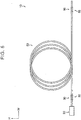
FIG. 5 is a schematic configuration diagram of the optical fiber laser device according to the first embodiment of the invention; -
FIG. 6 is a graph showing the analysis results of rare earth-doped fibers of examples included in the optical fiber laser device according to the first embodiment of the invention and a rare earth-doped fiber of a comparative example; -
FIG. 7A illustrates an oscillation mode of laser light in the optical fiber laser device according to the first embodiment of the invention; -
FIG. 7B illustrates an oscillation mode of laser light in the optical fiber laser device according to the first embodiment of the invention; -
FIG. 8A illustrates an oscillation mode of laser light in the optical fiber laser device according to the first embodiment of the invention; -
FIG. 8B illustrates an oscillation mode of laser light in the optical fiber laser device according to the first embodiment of the invention; -
FIG. 9A is a sectional view of a rare earth-doped fiber used in an optical fiber laser device according to a comparative form for the first embodiment of the invention; -
FIG. 9B is an enlarged sectional view ofFIG. 9A ; -
FIG. 10 is a schematic configuration diagram of the optical fiber laser device according to the comparative form for the first embodiment of the invention; -
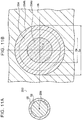
FIG. 11A is a sectional view of a rare earth-doped fiber used in an optical fiber laser device according to a second embodiment of the invention; -
FIG. 11B is an enlarged sectional view ofFIG. 11A ; -
FIG. 12 is a refractive index distribution diagram showing distribution of the refractive index of the rare earth-doped fiber included in the optical fiber laser device according to the second embodiment of the invention; -
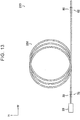
FIG. 13 is a schematic configuration diagram of the optical fiber laser device according to the second embodiment of the invention; -
FIG. 14 is a refractive index distribution diagram showing distribution of the refractive index of a rare earth-doped fiber included in an optical fiber laser device according to a modification of the embodiment of the invention; -
FIG. 15 is a refractive index distribution diagram showing distribution of the refractive index of a rare earth-doped fiber included in an optical fiber laser device according to a modification of the embodiment of the invention; and -
FIG. 16 is a refractive index distribution diagram showing distribution of the refractive index of a rare earth-doped fiber included in an optical fiber laser device according to a modification of the embodiment of the invention. - An example of an optical fiber laser device according to a first embodiment of the invention will be described with reference to
FIGS. 1 to 10 . Arrow H shown in the figures indicates the up-down direction of the device (vertical direction), and arrow W shown in the figures indicates the lateral direction of the vehicle (horizontal direction). - As shown in
FIG. 5 , an opticalfiber laser device 10 includes anexcitation light source 20 that outputs excitation light in a predetermined wavelength band, anoptical fiber 30 with a first fiber Bragg grating 32 (hereinafter referred to as the "first FBG 32"), and a rare earth-dopedfiber 50. The opticalfiber laser device 10 further includes anoptical fiber 80 with a second fiber Bragg grating 82 (hereinafter referred to as the "second FBG 82"). - The
excitation light source 20, theoptical fiber 30, the rare earth-dopedfiber 50, and theoptical fiber 80 are arranged in this order from one side to the other side in the lateral direction of the device. Theoptical fiber 30 is an example of the first fiber, and theoptical fiber 80 is an example of the second fiber. - The
excitation light source 20 is, e.g., a semiconductor laser etc. As shown inFIG. 5 , theexcitation light source 20 is disposed so as to face one end of theoptical fiber 30. Theexcitation light source 20 outputs excitation light toward the one end of theoptical fiber 30. In the present embodiment, theexcitation light source 20 outputs, e.g., excitation light with a wavelength of 975 nm. - As shown in
FIG. 5 , theoptical fiber 30 is linearly disposed such that its one end faces theexcitation light source 20 and that theoptical fiber 30 extends in the lateral direction of the device. Theoptical fiber 30 has its one end fused to theexcitation light source 20. As shown inFIG. 3A , theoptical fiber 30 has a core 34, acladding 36 covering thecore 34, and aresin cladding 38 covering thecladding 36. - The refractive index of the
cladding 36 is lower than that of the core 34, and the refractive index of theresin cladding 38 is significantly lower than that of thecladding 36. Thecore 34 is made of quartz doped with germanium, phosphorus, or aluminum, and thecladding 36 is made of quartz not doped with any dopant. Theresin cladding 38 is made of an ultraviolet curable resin. - In the present embodiment, the
core 34 has a diameter of 40 µm, thecladding 36 has a diameter of 400 µm, and theresin cladding 38 has a diameter of 800 µm. - As shown in
FIG. 4A , thefirst FBG 32 formed in theoptical fiber 30 has adiffraction grating 40. Thediffraction grating 40 has highrefractive index portions 40a and lowrefractive index portions 40b in thecore 34 of theoptical fiber 30. The highrefractive index portions 40a are arranged at regular intervals in the longitudinal direction of theoptical fiber 30 and have a higher refractive index than thecore 34. Each of the lowrefractive index portions 40b is located between a pair of highrefractive index portions 40a and has the same refractive index as thecore 34. The left-right direction inFIGS. 4A and 4B (arrow z in the figures) indicates the longitudinal direction of the fiber, and the up-down direction inFIGS. 4A and 4B (arrow r in the figures) indicates the radial direction of the fiber. - In the present embodiment, the reflection center wavelength (Bragg wavelength) of light reflected by the
first FBG 32 is, e.g., 1080 nm. The dimensions of each part, physical property values, etc. are determined so that thefirst FBG 32 reflects light with reflectance of 99% or more. - As shown in
FIG. 5 , theoptical fiber 80 is linearly disposed so as to extend in the lateral direction of the device. As shown inFIG. 3A , theoptical fiber 80 has a core 84, acladding 86 covering thecore 84, and aresin cladding 88 covering thecladding 86. - Each member of the
optical fiber 80 has a diameter similar to that of each member of theoptical fiber 30 and is made of a material similar to that of each member of theoptical fiber 30. - As shown in
FIG. 4B , thesecond FBG 82 formed in theoptical fiber 80 has adiffraction grating 90. Thediffraction grating 90 has highrefractive index portions 90a and lowrefractive index portions 90b in thecore 84 of theoptical fiber 80. The highrefractive index portions 90a are arranged at regular intervals in the longitudinal direction of theoptical fiber 80 and have a higher refractive index than thecore 84. Each of the lowrefractive index portions 90b is located between a pair of highrefractive index portions 90a and has the same refractive index as thecore 84. - In the present embodiment, the reflection center wavelength (Bragg wavelength) of light reflected by the
second FBG 82 is, e.g., 1080 nm like thefirst FBG 32. The reflectance of light reflected by thesecond FBG 82 is lower than that of light reflected by thefirst FBG 32. For example, in the present embodiment, the dimensions of each part, physical property values, etc. are determined so that thesecond FBG 82 reflects light with reflectance of 10%. - As shown in
FIG. 5 , the rare earth-dopedfiber 50 is disposed between theoptical fiber 30 and theoptical fiber 80 in the lateral direction of the device. The rare earth-dopedfiber 50 is wound in a coil shape with a large diameter so that no stress is produced in the rare earth-dopedfiber 50. - As shown in
FIG. 3B , the rare earth-dopedfiber 50 has a core 54 doped with a rare earth element, acladding 56 covering thecore 54, and aresin cladding 58 covering thecladding 56. - The refractive index of the
cladding 56 is lower than that of the core 54, and the refractive index of theresin cladding 58 is significantly lower than that of thecladding 56. Thecore 54 is made of quartz doped with ytterbium (Yb) that is an example of the rare earth element, and thecladding 56 is made of quartz not doped with any dopant. Theresin cladding 58 is made of an ultraviolet curable resin. The core 54 doped with the rare earth element will be described in detail later. - In the present embodiment, the
core 54 has a diameter of 40 µm, thecladding 56 has a diameter of 400 µm, and theresin cladding 58 has a diameter of 500 µm. The rare earth-dopedfiber 50 has a length of 9 m or more. - The rare earth-doped
fiber 50 has its one end fused to the other end of theoptical fiber 30 by arc discharge machining (seeFIG. 5 ). Specifically, thecore 34 and thecladding 36 of theoptical fiber 30 and thecore 54 and thecladding 56 of the rare earth-dopedfiber 50 are fused together by arc discharge (seeFIGS. 3A and 3B ). - The other end of the rare earth-doped
fiber 50 is fused to one end of theoptical fiber 80 by arc discharge machining (seeFIG. 5 ). Specifically, thecore 84 and thecladding 86 of theoptical fiber 80 and thecore 54 and thecladding 56 of the rare earth-dopedfiber 50 are fused together by arc discharge (seeFIGS. 3A and 3B ). - Next, the core 54 doped with the rare earth element will be described with reference to
FIGS. 1 and2 .FIG. 1 shows a section of the rare earth-dopedfiber 50 taken in a direction perpendicular to the longitudinal direction of the rare earth-dopedfiber 50.FIG. 2 is a refractive index distribution diagram showing distribution of the refractive index of the rare earth-dopedfiber 50. The up-down direction inFIG. 2 (arrow n in the figure) indicates the level of the refractive index, and the greater the height in the figure is, the higher the refractive index is. The left-right direction inFIG. 2 (arrow r in the figure) indicates the radial direction of the rare earth-dopedfiber 50. The dimensional ratios in the figures are exaggerated for convenience of description and may be different from the actual dimensional ratios. - As described above, the
core 54 of the rare earth-dopedfiber 50 is made of quartz doped with the rare earth element and has a diameter of 40 µm. - As shown in
FIGS. 1 and2 , the central portion of thecore 54 is doped with the rare earth element as viewed in the longitudinal direction of the rare earth-dopedfiber 50, and aportion 54a doped with the rare earth element has a circular section. The dopedportion 54a is shaded with dots in the figure. - The "central portion of the core 54" herein refers to a portion that includes the center C of the
core 54 and is located away from thecladding 56 as viewed in the longitudinal direction of the rare earth-dopedfiber 50. - In the present embodiment, the
portion 54a doped with the rare earth element is a cylindrical portion concentric with thecore 54 and having a predetermined diameter Da of 20 µm or more and 30 µm or less. In other words, theportion 54a doped with the rare earth element is a cylindrical portion with a predetermined diameter Da of Db / 2 or more and (3 · Db) / 4 or less, where Db represents the diameter of thecore 54. As described above, in the present embodiment, the central portion of thecore 54 is more heavily doped with the rare earth element than the peripheral portion of thecore 54 is. - The doped
portion 54a is doped with the rare earth element at a predetermined concentration in the range of 0.5 mass% or more and 10 mass% or less. The concentration of the rare earth element is preferably high in order for the rare earth element to be excited and spontaneously emit light with a specific wavelength and is preferably low in order for the dopedportion 54a to have a uniform concentration of the rare earth element. The dopedportion 54a is therefore preferably doped with the rare earth element at the concentration of 1 mass% or more and 2 mass% or less. - The
portion 54a of the core 54 which is doped with the rare earth element can be specified by analysis using an electron probe micro analyzer (EPMA). - Next, functions of the optical
fiber laser device 10 will be described by comparison with an opticalfiber laser device 510 according to a comparative form. First, the configuration of the opticalfiber laser device 510 will be described mainly with respect to differences from the opticalfiber laser device 10. Functions of the opticalfiber laser device 510 will also be described mainly with respect to differences from the opticalfiber laser device 10. - As shown in
FIG. 10 , the opticalfiber laser device 510 includes theexcitation light source 20, theoptical fiber 30, a rare earth-dopedfiber 550, and theoptical fiber 80. The rare earth-dopedfiber 550 is disposed between theoptical fiber 30 and theoptical fiber 80 in the lateral direction of the device. The rare earth-dopedfiber 550 is wound in a coil shape with a large diameter so that no stress is produced in the rare earth-dopedfiber 550. - As shown in
FIG. 9A , the rare earth-dopedfiber 550 has a core 554 doped with a rare earth element, thecladding 56 covering thecore 554, and theresin cladding 58 covering thecladding 56. Thecore 554 is made of quartz doped with the rare earth element and has a diameter of 40 µm. Theentire core 554 is uniformly doped with the rare earth element. In other words, the rare earth element is uniformly distributed in theentire core 554. In the present embodiment, thecore 554 is doped with the rare earth element at the concentration of 0.5 mass% or more and 10 mass% or less. - The rare earth-doped
fibers - First, the oscillation modes will be described. The following four oscillation modes were used in this analysis: LP01 mode, LP02 mode, LP03 mode, and LP04 mode.
-
FIGS. 7A, 7B ,8A, and 8B are graphs in which the X-axis and the Y-axis are coordinate axes indicating the position in a section of the core and the Z-axis represents radiant intensity. - As shown in
FIG. 7A , the LP01 mode is a single mode (unimodal) in which the output is the highest at the center of the core and an extreme value, namely the output higher than at surrounding locations, appears at one location. As shown inFIG. 7B , the LP02 mode is a multi-mode in which the output is the highest at the center of the core and extreme values, namely the output higher than at surrounding locations, appear in a circle pattern around the center of the core. - As shown in
FIG. 8A , the LP03 mode is a multi-mode in which the output is the highest at the center of the core and extreme values, namely the output higher than at surrounding locations, appear in a double-circle pattern around the center of the core. As shown inFIG. 8B , the LP04 mode is a multi-mode in which the output is the highest at the center of the core and extreme values, namely the output higher than at surrounding locations, appear in a triple-circle pattern around the center of the core. -
- 1. The rare earth-doped
fiber 50 in which theportion 54a concentric with thecore 54 and having a diameter of 20 µm was doped with the rare earth element was used as Example 1. - 2. The rare earth-doped
fiber 50 in which theportion 54a concentric with thecore 54 and having a diameter of 25 µm was doped with the rare earth element was used as Example 2. - 3. The rare earth-doped
fiber 50 in which theportion 54a concentric with thecore 54 and having a diameter of 30 µm was doped with the rare earth element was used as Example 3. - 4. The rare earth-doped
fiber 550 in which theentire core 554 was uniformly doped with the rare earth element was used as a comparative example. -
FIG. 6 is a graph in which the abscissa represents the oscillation mode and the ordinate represents the degree of amplification of the oscillation mode (hereinafter sometimes simply referred to as the "degree of amplification"). The continuous line in the graph indicates the analysis results of Example 1, the long dashed short dashed line in the graph indicates the analysis results of Example 2, and the long dashed double-short dashed line in the graph indicates the analysis results of Example 3. The dashed line in the graph indicates the analysis results of the comparative example. - As shown in the graph of
FIG. 6 , the degrees of amplification of the LP01 mode, the LP02 mode, the LP03 mode, and the LP04 mode were similar in the comparative example. That is, all the modes were amplified to the same degree in the comparative example. - For Examples 1, 2, and 3, as shown in the graph of
FIG. 6 , the degree of amplification of the LP01 mode was higher than the degrees of amplification of the other oscillation modes. The amplification ratio herein refers to the ratio of the degree of amplification of the LP01 mode to the degree of amplification of the LP02 mode. The amplification ratio of the first embodiment is 1.4, the amplification ratio of the second embodiment is 1.6, and the amplification ratio of the third embodiment is 1.2. The amplification ratio of the comparative example is 1.0. - That is, the amplification ratio is the highest when the diameter of the portion doped with the rare earth element is 25 µm, and the amplification ratio becomes lower when the diameter of the portion doped with the rare earth element is larger or smaller than 25 µm. That is, the amplification ratio is the highest when the diameter Da of the portion doped with the rare earth element is (5 · Db) / 8, and the amplification ratio becomes lower when the diameter Da of the portion doped with the rare earth element is larger or smaller than (5 · Db) / 8, where Db represents the diameter of the
core 54. Based on the knowledge that the degree of amplification of each oscillation mode changes according to the ratio between the diameter of the core and the diameter of the portion doped with the rare earth element, the portion doped with the rare earth element was nondimensionalized. - In the comparative example, the
entire core 554 is uniformly doped with the rare earth element, as described above. It is therefore considered that the degree of amplification of each oscillation mode is similar. - In Examples 1, 2 and 3, the central portion of the
core 54 is doped with the rare earth element, as described above. It is therefore considered that the degree of amplification of the LP01 mode is higher than the degrees of amplification of the other oscillation modes. - Next, functions of the optical
fiber laser devices - The
excitation light source 20 shown inFIGS. 5 and10 emits excitation light with a wavelength of 975 nm toward the one end of theoptical fiber 30. This excitation light enters thecladding 36 and thecore 34 of the optical fiber 30 (seeFIG. 3A ). The excitation light having propagated through theoptical fiber 30 enters the rare earth-dopedfiber - The excitation light having entered the rare earth-doped
fiber core fiber core fiber 50, 550 (seeFIG. 3B ) enters theoptical fiber 80. - Of the spontaneously emitted light having entered the
optical fiber 80, light in the reflection wavelength band (1080 nm in the present embodiment) of thesecond FBG 82 is reflected by thesecond FBG 82. The light reflected by thesecond FBG 82 returns to the rare earth-dopedfiber - The light having returned to the rare earth-doped
fiber optical fiber 30. - Of the light having entered the
optical fiber 30, light in the reflection wavelength band of the first FBG 32 (1080 nm in the present embodiment) is reflected by thefirst FBG 32. The light reflected by thefirst FBG 32 returns to the rare earth-dopedfiber fiber optical fiber 80. - As described above, the propagating light is gradually amplified as it travels back and forth between the
first FBG 32 and thesecond FBG 82. The light having exceeded oscillation conditions passes through thesecond FBG 82 and is output as laser light from the opticalfiber laser device - In the optical
fiber laser device 510, theentire core 554 is uniformly doped with the rare earth element. The degree of amplification of each oscillation mode is therefore similar, as described with respect to the above analysis results. Accordingly, it is difficult to selectively output single-mode laser light even when light travels back and forth between thefirst FBG 32 and the second FBG 82 a plurality of times. - In the optical
fiber laser device 10, on the other hand, the central portion of thecore 54 is doped with the rare earth element. The degree of amplification of the LP01 mode is therefore higher than the degrees of amplification of the other oscillation modes, as described with respect to the above analysis results. - Accordingly, light of the LP01 mode is amplified more than light of the other oscillation modes as light travels back and forth between the
first FBG 32 and the second FBG 82 a plurality of times. Laser light of the LP01 mode is thus output from the opticalfiber laser device 10. In other words, single-mode laser light is output from the opticalfiber laser device 10. - As described above, the optical
fiber laser device 10 efficiently outputs single-mode laser light as compared to the opticalfiber laser device 510 in which theentire core 554 is uniformly doped with the rare earth element. - In other words, the optical
fiber laser device 10 outputs laser light with better condensing properties as compared to the opticalfiber laser device 510 in which theentire core 554 is uniformly doped with the rare earth element. - In the optical
fiber laser device 10, the diameter Da of the portion doped with the rare earth element satisfies the following expression, where Db represents the diameter of thecore 54. - Db / 2 ≤ Da ≤ (3 · Db) / 4
- Accordingly, the optical
fiber laser device 10 effectively outputs single-mode laser light as compared to the case where the diameter Da is larger than (3 · Db) / 4 or smaller than Db / 2. - An example of an optical fiber laser device according to a second embodiment of the invention will be described with reference to
FIGS. 11A to 13 . The second embodiment will be described mainly with respect to differences from the first embodiment. - As shown in
FIG. 13 , an opticalfiber laser device 210 according to the second embodiment includes theexcitation light source 20, theoptical fiber 30, a rare earth-dopedfiber 250, and theoptical fiber 80. The rare earth-dopedfiber 250 is disposed between theoptical fiber 30 and theoptical fiber 80 in the lateral direction of the device. The rare earth-dopedfiber 250 is wound in a coil shape with a large diameter so that no stress is produced in the rare earth-dopedfiber 250. - As shown in
FIG. 11A , the rare earth-dopedfiber 250 has a core 254 doped with a rare earth element, thecladding 56 covering thecore 254, and theresin cladding 58 covering thecladding 56. - As described above, the
core 254 is made of quartz doped with the rare earth element and has a diameter of 40 µm. Specifically, as shown inFIGS. 11B and12 , the central portion of thecore 254 is doped with the rare earth element, and aportion 254a doped with the rare earth element has a circular section. Specifically, theportion 54a doped with the rare earth element is a cylindrical portion concentric with thecore 54 and having a predetermined diameter Da of 20 µm or more and 30 µm or less. - The
core 254 has an absorbingportion 254b in the peripheral portion of thecore 254. The absorbingportion 254b is formed in a portion different from the dopedportion 54a and absorbs light in a wavelength band to be output without the absorbing excitation light. The absorbingportion 254b is formed along the entire circumference of thecore 254. For example, when the wavelength of excitation light is 975 nm and the rare earth element is ytterbium (Yb), the absorbingportion 254b is a hollow cylindrical portion made of samarium (Sm)-doped quartz and absorbs about 20% of light in the output wavelength band as compared to the remaining portion of thecore 254. - Since the absorbing
portion 254b that absorbs light in the output wavelength band is formed in the peripheral portion of thecore 254, light that is output from the peripheral portion of thecore 254 has reduced radiant intensity. The opticalfiber laser device 210 thus efficiently outputs single-mode laser light as compared to the case where thecore 254 does not have the absorbingportion 254b. - The other functions of the second embodiment are the same as the functions of the first embodiment.
- Although the invention is described above in detail with respect to the specific embodiments, the invention is not limited to such embodiments, and various other embodiments are possible within the spirit and scope of the invention. For example, in the first and second embodiments, the central portion of the core 54, 254 is doped with the rare earth element, and the peripheral portion of the core 54, 254 is not doped with the rare earth element. However, the peripheral portion of the core may be doped with the rare earth element. The central portion of the core 54, 254 need only be more heavily doped with the rare earth element than the peripheral portion of the core 54, 254 is.
- In the first and second embodiments, the
portions doped portions doped portions cladding 56. In this case, the function that is implemented by the dopedportions - In the first and second embodiments, the
cores fibers excitation light source 20. - In the second embodiment, the absorbing
portion 254b is doped with samarium (Sm). However, the absorbingportion 254b may be doped with europium (Eu) etc. depending on the wavelength of laser light to be absorbed by the absorbingportion 254b. - Although not particularly described in the first embodiment, the doped
portion 54a may have a higher refractive index than the core 54 except for the dopedportion 54a as shown inFIG. 14 or may have a lower refractive index than the core 54 except for the dopedportion 54a as shown inFIG. 15 . - Although not particularly described in the first embodiment, the doped
portion 54a may have a lower refractive index than the core 54 except for the dopedportion 54a as shown inFIG. 16 . A cylindrical central portion 54c, which is the center of thecore 54 and has a diameter of 1 µm or more and 2 µm or less, is not doped with a rare earth element and has a higher refractive index than the dopedportion 54a. The central portion 54c may have a higher refractive index than the portion of the core 54 which is not doped with a rare earth element. The central portion of the core 54 need only be more heavily doped with the rare earth element than the peripheral portion of thecore 54 is.
Claims (4)
- An optical fiber laser device (10; 210), comprising:a first fiber (30) having a first fiber Bragg grating;a second fiber (80) having a second fiber Bragg grating with lower reflectance than the first fiber Bragg grating; anda third fiber (50) doped with a rare earth element, having a first end connected with the first fiber (30), and having a second end connected with the second fiber (80), whereina central portion of a core (54) of the third fiber (50) is more heavily doped with the rare earth element than a peripheral portion of the core is.
- The optical fiber laser device (10; 210) according to claim 1, wherein:the central portion of the core (54) is doped with the rare earth element and the peripheral portion of the core (54) is not doped with the rare earth element; andthe following expression is satisfied, where Da represents a diameter of the central portion doped with the rare earth element and Db represents a diameter of the core (54)
Db / 2 ≤ Da ≤ (3 · Db) / 4. - The optical fiber laser device (210) according to claim 1 or 2, wherein the peripheral portion of the core (54) includes an absorbing portion (254b) that absorbs light in an output wavelength band.
- The optical fiber laser device (210) according to claim 3, wherein:the rare earth element is ytterbium; andthe absorbing portion (254b) is samarium-doped quartz.
Applications Claiming Priority (1)
| Application Number | Priority Date | Filing Date | Title |
|---|---|---|---|
| JP2019087569A JP7136534B2 (en) | 2019-05-07 | 2019-05-07 | Optical fiber laser device |
Publications (3)
| Publication Number | Publication Date |
|---|---|
| EP3736921A2 true EP3736921A2 (en) | 2020-11-11 |
| EP3736921A3 EP3736921A3 (en) | 2020-11-18 |
| EP3736921B1 EP3736921B1 (en) | 2022-03-16 |
Family
ID=70553732
Family Applications (1)
| Application Number | Title | Priority Date | Filing Date |
|---|---|---|---|
| EP20172678.3A Active EP3736921B1 (en) | 2019-05-07 | 2020-05-04 | Optical fiber laser device |
Country Status (8)
| Country | Link |
|---|---|
| US (1) | US11424589B2 (en) |
| EP (1) | EP3736921B1 (en) |
| JP (1) | JP7136534B2 (en) |
| KR (1) | KR20200129044A (en) |
| CN (1) | CN111916980B (en) |
| BR (1) | BR102020008924A2 (en) |
| MX (1) | MX2020004701A (en) |
| RU (1) | RU2740005C1 (en) |
Citations (1)
| Publication number | Priority date | Publication date | Assignee | Title |
|---|---|---|---|---|
| JP2007273600A (en) | 2006-03-30 | 2007-10-18 | Furukawa Electric Co Ltd:The | Optical fiber laser |
Family Cites Families (32)
| Publication number | Priority date | Publication date | Assignee | Title |
|---|---|---|---|---|
| WO1991013038A1 (en) * | 1990-02-28 | 1991-09-05 | Otc Limited | A rare-earth doped fibre |
| US5121460A (en) * | 1991-01-31 | 1992-06-09 | The Charles Stark Draper Lab., Inc. | High-power mode-selective optical fiber laser |
| US5187759A (en) * | 1991-11-07 | 1993-02-16 | At&T Bell Laboratories | High gain multi-mode optical amplifier |
| JP3228451B2 (en) | 1994-01-26 | 2001-11-12 | 日本電信電話株式会社 | Optical fiber amplifier |
| US5530710A (en) * | 1995-05-15 | 1996-06-25 | At&T Corp. | High-power pumping of three-level optical fiber laser amplifier |
| JP3622816B2 (en) * | 1996-12-27 | 2005-02-23 | 富士通株式会社 | Optical amplification fiber and manufacturing method thereof |
| US5818630A (en) * | 1997-06-25 | 1998-10-06 | Imra America, Inc. | Single-mode amplifiers and compressors based on multi-mode fibers |
| JP4947853B2 (en) | 2001-06-25 | 2012-06-06 | 三菱電線工業株式会社 | Rare earth element doped fiber |
| WO2003067723A1 (en) | 2002-02-06 | 2003-08-14 | Mitsubishi Denki Kabushiki Kaisha | Multimode optical fiber, fiber laser amplifier, and fiber laser oscillator |
| US7787729B2 (en) * | 2005-05-20 | 2010-08-31 | Imra America, Inc. | Single mode propagation in fibers and rods with large leakage channels |
| US20080144673A1 (en) | 2006-12-15 | 2008-06-19 | Ipg Photonics Corporation | Fiber laser with large mode area fiber |
| CN101663604A (en) * | 2007-02-28 | 2010-03-03 | 康宁股份有限公司 | Optical fiber with large effective area |
| WO2009057309A1 (en) * | 2007-10-31 | 2009-05-07 | Panasonic Corporation | Fiber laser light source |
| CN101320109A (en) * | 2008-06-13 | 2008-12-10 | 华中科技大学 | A Rare Earth Ion Doped Ring Double-clad Optical Fiber |
| US20090316733A1 (en) * | 2008-06-20 | 2009-12-24 | Bing Yao | Optical fiber for a fiber laser and fiber laser using the same |
| DE102008047736B3 (en) * | 2008-07-07 | 2010-01-21 | Heraeus Quarzglas Gmbh & Co. Kg | Biegeunempfindliche optical fiber, quartz glass tube as a semi-finished product for its production and method for producing the fiber |
| EP2321678B1 (en) * | 2008-08-18 | 2018-12-26 | NKT Photonics A/S | Optical fiber with resonant structure of cladding features connected to light sink |
| JP5171569B2 (en) * | 2008-11-19 | 2013-03-27 | 浜松ホトニクス株式会社 | Fiber optic plate and manufacturing method thereof |
| JP2010167433A (en) | 2009-01-21 | 2010-08-05 | Omron Corp | Laser beam applying device and laser beam machining apparatus |
| JP4672071B2 (en) * | 2009-05-28 | 2011-04-20 | 株式会社フジクラ | Fiber laser equipment |
| US8204349B2 (en) * | 2009-10-28 | 2012-06-19 | Ipg Photonics Corporation | Optical fiber with multiple ring-shaped core regions |
| US8498044B2 (en) | 2009-12-22 | 2013-07-30 | Fujikura Ltd. | Amplification optical fiber, and optical fiber amplifier and resonator using the same |
| JP2013032241A (en) * | 2011-08-01 | 2013-02-14 | Sumitomo Electric Ind Ltd | Method for making optical fiber preform |
| JP5771586B2 (en) * | 2012-10-16 | 2015-09-02 | 株式会社フジクラ | Optical fiber and fiber laser device using the same |
| JP5779606B2 (en) | 2013-03-14 | 2015-09-16 | 株式会社フジクラ | Amplifying optical fiber and fiber laser device using the same |
| CN103955020B (en) * | 2014-04-17 | 2017-01-18 | 中天科技精密材料有限公司 | Low-loss large-effective-area single-mode optical fiber and manufacturing method thereof |
| JP6536036B2 (en) * | 2015-01-14 | 2019-07-03 | 住友電気工業株式会社 | Optical fiber |
| CN104793285B (en) * | 2015-04-29 | 2018-01-02 | 武汉邮电科学研究院 | Low-loss less fundamental mode optical fibre |
| JP6571562B2 (en) * | 2016-03-03 | 2019-09-04 | 日本電信電話株式会社 | Amplifying optical fiber design method |
| JP2017181777A (en) | 2016-03-30 | 2017-10-05 | 株式会社豊田中央研究所 | Modification method of transparent optical material, optical device, method for manufacturing optical device, and apparatus for manufacturing optical device |
| JP6668272B2 (en) | 2017-01-27 | 2020-03-18 | 株式会社フジクラ | Optical fiber for amplification |
| CN108761635B (en) * | 2018-05-03 | 2019-12-31 | 烽火通信科技股份有限公司 | Double-clad ytterbium-doped optical fiber |
-
2019
- 2019-05-07 JP JP2019087569A patent/JP7136534B2/en active Active
-
2020
- 2020-04-30 RU RU2020115235A patent/RU2740005C1/en active
- 2020-04-30 CN CN202010368078.4A patent/CN111916980B/en active Active
- 2020-05-04 KR KR1020200053206A patent/KR20200129044A/en not_active Ceased
- 2020-05-04 US US16/865,478 patent/US11424589B2/en active Active
- 2020-05-04 EP EP20172678.3A patent/EP3736921B1/en active Active
- 2020-05-05 BR BR102020008924-2A patent/BR102020008924A2/en not_active IP Right Cessation
- 2020-07-13 MX MX2020004701A patent/MX2020004701A/en unknown
Patent Citations (1)
| Publication number | Priority date | Publication date | Assignee | Title |
|---|---|---|---|---|
| JP2007273600A (en) | 2006-03-30 | 2007-10-18 | Furukawa Electric Co Ltd:The | Optical fiber laser |
Also Published As
| Publication number | Publication date |
|---|---|
| BR102020008924A2 (en) | 2020-12-01 |
| US20200358245A1 (en) | 2020-11-12 |
| RU2740005C1 (en) | 2020-12-30 |
| EP3736921A3 (en) | 2020-11-18 |
| KR20200129044A (en) | 2020-11-17 |
| JP7136534B2 (en) | 2022-09-13 |
| CN111916980A (en) | 2020-11-10 |
| JP2020184565A (en) | 2020-11-12 |
| MX2020004701A (en) | 2020-11-09 |
| US11424589B2 (en) | 2022-08-23 |
| EP3736921B1 (en) | 2022-03-16 |
| CN111916980B (en) | 2024-12-24 |
Similar Documents
| Publication | Publication Date | Title |
|---|---|---|
| JP5977215B2 (en) | Fiber that provides double-clad gain with increased cladding absorption while maintaining single-mode operation | |
| EP2082462B1 (en) | Photonic bandgap fiber and fiber amplifier | |
| US6987783B2 (en) | Three-level air-clad rare-earth doped fiber laser/amplifier | |
| EP2503653A1 (en) | Amplifying optical fiber, and optical fiber amplifier and resonator using same | |
| US20200161826A1 (en) | Multimode fiber, optical amplifier, and fiber laser | |
| CN105009387B (en) | Photon band-gap optical fiber and the fiber laser device using photon band-gap optical fiber | |
| JPWO2009104691A1 (en) | Optical fiber laser | |
| US20220094131A1 (en) | Active element-added optical fiber, resonator, and fiber laser device | |
| EP3736921B1 (en) | Optical fiber laser device | |
| JP6306638B2 (en) | Fiber that provides gain with increased cladding absorption while maintaining single mode operation | |
| US11835776B2 (en) | Filter device and laser apparatus | |
| JP4799810B2 (en) | Double clad fiber and optical amplification method using the same | |
| EP4287423B1 (en) | Rare-earth-doped fiber and fiber laser device | |
| EP3176886A1 (en) | Optical fiber, fiber amplifier, and fiber laser | |
| WO2020203930A1 (en) | Active element added-optical fiber, resonator, and fiber laser device | |
| CN113474952A (en) | Active element-added optical fiber, resonator, and fiber laser device |
Legal Events
| Date | Code | Title | Description |
|---|---|---|---|
| PUAI | Public reference made under article 153(3) epc to a published international application that has entered the european phase |
Free format text: ORIGINAL CODE: 0009012 |
|
| STAA | Information on the status of an ep patent application or granted ep patent |
Free format text: STATUS: REQUEST FOR EXAMINATION WAS MADE |
|
| PUAL | Search report despatched |
Free format text: ORIGINAL CODE: 0009013 |
|
| 17P | Request for examination filed |
Effective date: 20200504 |
|
| AK | Designated contracting states |
Kind code of ref document: A2 Designated state(s): AL AT BE BG CH CY CZ DE DK EE ES FI FR GB GR HR HU IE IS IT LI LT LU LV MC MK MT NL NO PL PT RO RS SE SI SK SM TR |
|
| AX | Request for extension of the european patent |
Extension state: BA ME |
|
| AK | Designated contracting states |
Kind code of ref document: A3 Designated state(s): AL AT BE BG CH CY CZ DE DK EE ES FI FR GB GR HR HU IE IS IT LI LT LU LV MC MK MT NL NO PL PT RO RS SE SI SK SM TR |
|
| AX | Request for extension of the european patent |
Extension state: BA ME |
|
| RIC1 | Information provided on ipc code assigned before grant |
Ipc: H01S 3/094 20060101ALN20201014BHEP Ipc: H01S 3/08 20060101ALI20201014BHEP Ipc: H01S 3/0941 20060101ALN20201014BHEP Ipc: H01S 3/067 20060101AFI20201014BHEP Ipc: H01S 3/16 20060101ALN20201014BHEP Ipc: H01S 3/17 20060101ALN20201014BHEP |
|
| GRAP | Despatch of communication of intention to grant a patent |
Free format text: ORIGINAL CODE: EPIDOSNIGR1 |
|
| STAA | Information on the status of an ep patent application or granted ep patent |
Free format text: STATUS: GRANT OF PATENT IS INTENDED |
|
| RIC1 | Information provided on ipc code assigned before grant |
Ipc: H01S 3/17 20060101ALN20211001BHEP Ipc: H01S 3/16 20060101ALN20211001BHEP Ipc: H01S 3/0941 20060101ALN20211001BHEP Ipc: H01S 3/094 20060101ALN20211001BHEP Ipc: H01S 3/08 20060101ALI20211001BHEP Ipc: H01S 3/067 20060101AFI20211001BHEP |
|
| INTG | Intention to grant announced |
Effective date: 20211026 |
|
| GRAS | Grant fee paid |
Free format text: ORIGINAL CODE: EPIDOSNIGR3 |
|
| GRAA | (expected) grant |
Free format text: ORIGINAL CODE: 0009210 |
|
| STAA | Information on the status of an ep patent application or granted ep patent |
Free format text: STATUS: THE PATENT HAS BEEN GRANTED |
|
| RAP3 | Party data changed (applicant data changed or rights of an application transferred) |
Owner name: TOYOTA SCHOOL FOUNDATION Owner name: TOYOTA JIDOSHA KABUSHIKI KAISHA |
|
| RIN1 | Information on inventor provided before grant (corrected) |
Inventor name: HALDER, ARINDAM Inventor name: SAITO, KAZUYA Inventor name: OKAZAKI, TOMOYA Inventor name: KATO, SATORU Inventor name: INOUE, DAISUKE Inventor name: HASEGAWA, KAZUO |
|
| AK | Designated contracting states |
Kind code of ref document: B1 Designated state(s): AL AT BE BG CH CY CZ DE DK EE ES FI FR GB GR HR HU IE IS IT LI LT LU LV MC MK MT NL NO PL PT RO RS SE SI SK SM TR |
|
| REG | Reference to a national code |
Ref country code: GB Ref legal event code: FG4D |
|
| REG | Reference to a national code |
Ref country code: CH Ref legal event code: EP |
|
| REG | Reference to a national code |
Ref country code: DE Ref legal event code: R096 Ref document number: 602020002209 Country of ref document: DE |
|
| REG | Reference to a national code |
Ref country code: IE Ref legal event code: FG4D |
|
| REG | Reference to a national code |
Ref country code: AT Ref legal event code: REF Ref document number: 1476559 Country of ref document: AT Kind code of ref document: T Effective date: 20220415 |
|
| REG | Reference to a national code |
Ref country code: LT Ref legal event code: MG9D |
|
| REG | Reference to a national code |
Ref country code: NL Ref legal event code: MP Effective date: 20220316 |
|
| PG25 | Lapsed in a contracting state [announced via postgrant information from national office to epo] |
Ref country code: SE Free format text: LAPSE BECAUSE OF FAILURE TO SUBMIT A TRANSLATION OF THE DESCRIPTION OR TO PAY THE FEE WITHIN THE PRESCRIBED TIME-LIMIT Effective date: 20220316 Ref country code: RS Free format text: LAPSE BECAUSE OF FAILURE TO SUBMIT A TRANSLATION OF THE DESCRIPTION OR TO PAY THE FEE WITHIN THE PRESCRIBED TIME-LIMIT Effective date: 20220316 Ref country code: NO Free format text: LAPSE BECAUSE OF FAILURE TO SUBMIT A TRANSLATION OF THE DESCRIPTION OR TO PAY THE FEE WITHIN THE PRESCRIBED TIME-LIMIT Effective date: 20220616 Ref country code: LT Free format text: LAPSE BECAUSE OF FAILURE TO SUBMIT A TRANSLATION OF THE DESCRIPTION OR TO PAY THE FEE WITHIN THE PRESCRIBED TIME-LIMIT Effective date: 20220316 Ref country code: HR Free format text: LAPSE BECAUSE OF FAILURE TO SUBMIT A TRANSLATION OF THE DESCRIPTION OR TO PAY THE FEE WITHIN THE PRESCRIBED TIME-LIMIT Effective date: 20220316 Ref country code: BG Free format text: LAPSE BECAUSE OF FAILURE TO SUBMIT A TRANSLATION OF THE DESCRIPTION OR TO PAY THE FEE WITHIN THE PRESCRIBED TIME-LIMIT Effective date: 20220616 |
|
| REG | Reference to a national code |
Ref country code: AT Ref legal event code: MK05 Ref document number: 1476559 Country of ref document: AT Kind code of ref document: T Effective date: 20220316 |
|
| PG25 | Lapsed in a contracting state [announced via postgrant information from national office to epo] |
Ref country code: LV Free format text: LAPSE BECAUSE OF FAILURE TO SUBMIT A TRANSLATION OF THE DESCRIPTION OR TO PAY THE FEE WITHIN THE PRESCRIBED TIME-LIMIT Effective date: 20220316 Ref country code: GR Free format text: LAPSE BECAUSE OF FAILURE TO SUBMIT A TRANSLATION OF THE DESCRIPTION OR TO PAY THE FEE WITHIN THE PRESCRIBED TIME-LIMIT Effective date: 20220617 Ref country code: FI Free format text: LAPSE BECAUSE OF FAILURE TO SUBMIT A TRANSLATION OF THE DESCRIPTION OR TO PAY THE FEE WITHIN THE PRESCRIBED TIME-LIMIT Effective date: 20220316 |
|
| PG25 | Lapsed in a contracting state [announced via postgrant information from national office to epo] |
Ref country code: NL Free format text: LAPSE BECAUSE OF FAILURE TO SUBMIT A TRANSLATION OF THE DESCRIPTION OR TO PAY THE FEE WITHIN THE PRESCRIBED TIME-LIMIT Effective date: 20220316 |
|
| PG25 | Lapsed in a contracting state [announced via postgrant information from national office to epo] |
Ref country code: SM Free format text: LAPSE BECAUSE OF FAILURE TO SUBMIT A TRANSLATION OF THE DESCRIPTION OR TO PAY THE FEE WITHIN THE PRESCRIBED TIME-LIMIT Effective date: 20220316 Ref country code: SK Free format text: LAPSE BECAUSE OF FAILURE TO SUBMIT A TRANSLATION OF THE DESCRIPTION OR TO PAY THE FEE WITHIN THE PRESCRIBED TIME-LIMIT Effective date: 20220316 Ref country code: RO Free format text: LAPSE BECAUSE OF FAILURE TO SUBMIT A TRANSLATION OF THE DESCRIPTION OR TO PAY THE FEE WITHIN THE PRESCRIBED TIME-LIMIT Effective date: 20220316 Ref country code: PT Free format text: LAPSE BECAUSE OF FAILURE TO SUBMIT A TRANSLATION OF THE DESCRIPTION OR TO PAY THE FEE WITHIN THE PRESCRIBED TIME-LIMIT Effective date: 20220718 Ref country code: ES Free format text: LAPSE BECAUSE OF FAILURE TO SUBMIT A TRANSLATION OF THE DESCRIPTION OR TO PAY THE FEE WITHIN THE PRESCRIBED TIME-LIMIT Effective date: 20220316 Ref country code: EE Free format text: LAPSE BECAUSE OF FAILURE TO SUBMIT A TRANSLATION OF THE DESCRIPTION OR TO PAY THE FEE WITHIN THE PRESCRIBED TIME-LIMIT Effective date: 20220316 Ref country code: CZ Free format text: LAPSE BECAUSE OF FAILURE TO SUBMIT A TRANSLATION OF THE DESCRIPTION OR TO PAY THE FEE WITHIN THE PRESCRIBED TIME-LIMIT Effective date: 20220316 Ref country code: AT Free format text: LAPSE BECAUSE OF FAILURE TO SUBMIT A TRANSLATION OF THE DESCRIPTION OR TO PAY THE FEE WITHIN THE PRESCRIBED TIME-LIMIT Effective date: 20220316 |
|
| PG25 | Lapsed in a contracting state [announced via postgrant information from national office to epo] |
Ref country code: PL Free format text: LAPSE BECAUSE OF FAILURE TO SUBMIT A TRANSLATION OF THE DESCRIPTION OR TO PAY THE FEE WITHIN THE PRESCRIBED TIME-LIMIT Effective date: 20220316 Ref country code: IS Free format text: LAPSE BECAUSE OF FAILURE TO SUBMIT A TRANSLATION OF THE DESCRIPTION OR TO PAY THE FEE WITHIN THE PRESCRIBED TIME-LIMIT Effective date: 20220716 Ref country code: AL Free format text: LAPSE BECAUSE OF FAILURE TO SUBMIT A TRANSLATION OF THE DESCRIPTION OR TO PAY THE FEE WITHIN THE PRESCRIBED TIME-LIMIT Effective date: 20220316 |
|
| REG | Reference to a national code |
Ref country code: DE Ref legal event code: R097 Ref document number: 602020002209 Country of ref document: DE |
|
| PLBE | No opposition filed within time limit |
Free format text: ORIGINAL CODE: 0009261 |
|
| STAA | Information on the status of an ep patent application or granted ep patent |
Free format text: STATUS: NO OPPOSITION FILED WITHIN TIME LIMIT |
|
| REG | Reference to a national code |
Ref country code: BE Ref legal event code: MM Effective date: 20220531 |
|
| PG25 | Lapsed in a contracting state [announced via postgrant information from national office to epo] |
Ref country code: MC Free format text: LAPSE BECAUSE OF FAILURE TO SUBMIT A TRANSLATION OF THE DESCRIPTION OR TO PAY THE FEE WITHIN THE PRESCRIBED TIME-LIMIT Effective date: 20220316 Ref country code: LU Free format text: LAPSE BECAUSE OF NON-PAYMENT OF DUE FEES Effective date: 20220504 Ref country code: DK Free format text: LAPSE BECAUSE OF FAILURE TO SUBMIT A TRANSLATION OF THE DESCRIPTION OR TO PAY THE FEE WITHIN THE PRESCRIBED TIME-LIMIT Effective date: 20220316 |
|
| 26N | No opposition filed |
Effective date: 20221219 |
|
| PG25 | Lapsed in a contracting state [announced via postgrant information from national office to epo] |
Ref country code: SI Free format text: LAPSE BECAUSE OF FAILURE TO SUBMIT A TRANSLATION OF THE DESCRIPTION OR TO PAY THE FEE WITHIN THE PRESCRIBED TIME-LIMIT Effective date: 20220316 |
|
| PG25 | Lapsed in a contracting state [announced via postgrant information from national office to epo] |
Ref country code: IE Free format text: LAPSE BECAUSE OF NON-PAYMENT OF DUE FEES Effective date: 20220504 |
|
| PG25 | Lapsed in a contracting state [announced via postgrant information from national office to epo] |
Ref country code: BE Free format text: LAPSE BECAUSE OF NON-PAYMENT OF DUE FEES Effective date: 20220531 |
|
| PG25 | Lapsed in a contracting state [announced via postgrant information from national office to epo] |
Ref country code: IT Free format text: LAPSE BECAUSE OF FAILURE TO SUBMIT A TRANSLATION OF THE DESCRIPTION OR TO PAY THE FEE WITHIN THE PRESCRIBED TIME-LIMIT Effective date: 20220316 |
|
| REG | Reference to a national code |
Ref country code: CH Ref legal event code: PL |
|
| PG25 | Lapsed in a contracting state [announced via postgrant information from national office to epo] |
Ref country code: LI Free format text: LAPSE BECAUSE OF NON-PAYMENT OF DUE FEES Effective date: 20230531 Ref country code: CH Free format text: LAPSE BECAUSE OF NON-PAYMENT OF DUE FEES Effective date: 20230531 |
|
| PG25 | Lapsed in a contracting state [announced via postgrant information from national office to epo] |
Ref country code: MK Free format text: LAPSE BECAUSE OF FAILURE TO SUBMIT A TRANSLATION OF THE DESCRIPTION OR TO PAY THE FEE WITHIN THE PRESCRIBED TIME-LIMIT Effective date: 20220316 Ref country code: CY Free format text: LAPSE BECAUSE OF FAILURE TO SUBMIT A TRANSLATION OF THE DESCRIPTION OR TO PAY THE FEE WITHIN THE PRESCRIBED TIME-LIMIT Effective date: 20220316 |
|
| PG25 | Lapsed in a contracting state [announced via postgrant information from national office to epo] |
Ref country code: HU Free format text: LAPSE BECAUSE OF FAILURE TO SUBMIT A TRANSLATION OF THE DESCRIPTION OR TO PAY THE FEE WITHIN THE PRESCRIBED TIME-LIMIT; INVALID AB INITIO Effective date: 20200504 |
|
| PG25 | Lapsed in a contracting state [announced via postgrant information from national office to epo] |
Ref country code: MT Free format text: LAPSE BECAUSE OF FAILURE TO SUBMIT A TRANSLATION OF THE DESCRIPTION OR TO PAY THE FEE WITHIN THE PRESCRIBED TIME-LIMIT Effective date: 20220316 |
|
| PGFP | Annual fee paid to national office [announced via postgrant information from national office to epo] |
Ref country code: GB Payment date: 20250327 Year of fee payment: 6 |
|
| PGFP | Annual fee paid to national office [announced via postgrant information from national office to epo] |
Ref country code: DE Payment date: 20250402 Year of fee payment: 6 |
|
| PGFP | Annual fee paid to national office [announced via postgrant information from national office to epo] |
Ref country code: FR Payment date: 20250401 Year of fee payment: 6 |
|
| PG25 | Lapsed in a contracting state [announced via postgrant information from national office to epo] |
Ref country code: TR Free format text: LAPSE BECAUSE OF FAILURE TO SUBMIT A TRANSLATION OF THE DESCRIPTION OR TO PAY THE FEE WITHIN THE PRESCRIBED TIME-LIMIT Effective date: 20220316 |
|
| REG | Reference to a national code |
Ref country code: DE Ref legal event code: R084 Ref document number: 602020002209 Country of ref document: DE |