EP3736792A1 - Display device - Google Patents
Display device Download PDFInfo
- Publication number
- EP3736792A1 EP3736792A1 EP20173287.2A EP20173287A EP3736792A1 EP 3736792 A1 EP3736792 A1 EP 3736792A1 EP 20173287 A EP20173287 A EP 20173287A EP 3736792 A1 EP3736792 A1 EP 3736792A1
- Authority
- EP
- European Patent Office
- Prior art keywords
- protection
- support portion
- support
- display device
- exemplary embodiment
- Prior art date
- Legal status (The legal status is an assumption and is not a legal conclusion. Google has not performed a legal analysis and makes no representation as to the accuracy of the status listed.)
- Granted
Links
Images









Classifications
-
- G—PHYSICS
- G06—COMPUTING OR CALCULATING; COUNTING
- G06F—ELECTRIC DIGITAL DATA PROCESSING
- G06F1/00—Details not covered by groups G06F3/00 - G06F13/00 and G06F21/00
- G06F1/16—Constructional details or arrangements
- G06F1/1613—Constructional details or arrangements for portable computers
- G06F1/1633—Constructional details or arrangements of portable computers not specific to the type of enclosures covered by groups G06F1/1615 - G06F1/1626
- G06F1/1675—Miscellaneous details related to the relative movement between the different enclosures or enclosure parts
- G06F1/1681—Details related solely to hinges
-
- G—PHYSICS
- G09—EDUCATION; CRYPTOGRAPHY; DISPLAY; ADVERTISING; SEALS
- G09F—DISPLAYING; ADVERTISING; SIGNS; LABELS OR NAME-PLATES; SEALS
- G09F9/00—Indicating arrangements for variable information in which the information is built-up on a support by selection or combination of individual elements
- G09F9/30—Indicating arrangements for variable information in which the information is built-up on a support by selection or combination of individual elements in which the desired character or characters are formed by combining individual elements
- G09F9/301—Indicating arrangements for variable information in which the information is built-up on a support by selection or combination of individual elements in which the desired character or characters are formed by combining individual elements flexible foldable or roll-able electronic displays, e.g. thin LCD, OLED
-
- F—MECHANICAL ENGINEERING; LIGHTING; HEATING; WEAPONS; BLASTING
- F16—ENGINEERING ELEMENTS AND UNITS; GENERAL MEASURES FOR PRODUCING AND MAINTAINING EFFECTIVE FUNCTIONING OF MACHINES OR INSTALLATIONS; THERMAL INSULATION IN GENERAL
- F16C—SHAFTS; FLEXIBLE SHAFTS; ELEMENTS OR CRANKSHAFT MECHANISMS; ROTARY BODIES OTHER THAN GEARING ELEMENTS; BEARINGS
- F16C11/00—Pivots; Pivotal connections
- F16C11/04—Pivotal connections
-
- G—PHYSICS
- G06—COMPUTING OR CALCULATING; COUNTING
- G06F—ELECTRIC DIGITAL DATA PROCESSING
- G06F1/00—Details not covered by groups G06F3/00 - G06F13/00 and G06F21/00
- G06F1/16—Constructional details or arrangements
- G06F1/1613—Constructional details or arrangements for portable computers
-
- G—PHYSICS
- G06—COMPUTING OR CALCULATING; COUNTING
- G06F—ELECTRIC DIGITAL DATA PROCESSING
- G06F1/00—Details not covered by groups G06F3/00 - G06F13/00 and G06F21/00
- G06F1/16—Constructional details or arrangements
- G06F1/1613—Constructional details or arrangements for portable computers
- G06F1/1633—Constructional details or arrangements of portable computers not specific to the type of enclosures covered by groups G06F1/1615 - G06F1/1626
- G06F1/1637—Details related to the display arrangement, including those related to the mounting of the display in the housing
- G06F1/1652—Details related to the display arrangement, including those related to the mounting of the display in the housing the display being flexible, e.g. mimicking a sheet of paper, or rollable
-
- G—PHYSICS
- G06—COMPUTING OR CALCULATING; COUNTING
- G06F—ELECTRIC DIGITAL DATA PROCESSING
- G06F2203/00—Indexing scheme relating to G06F3/00 - G06F3/048
- G06F2203/041—Indexing scheme relating to G06F3/041 - G06F3/045
- G06F2203/04102—Flexible digitiser, i.e. constructional details for allowing the whole digitising part of a device to be flexed or rolled like a sheet of paper
Definitions
- Exemplary embodiments of the invention relate to a display device, and more particularly, to a display device capable of substantially preventing damage to a display panel.
- a deformable display device such as a flexible or foldable display device generally includes a display panel that may be bendable. Since a curved portion of a display panel is more stressed than other portions thereof, the curved portion may be vulnerable to an impact from an outside.
- Exemplary embodiments of the invention may be directed to a display device capable of substantially preventing damage to a display panel.
- An exemplary embodiment provides a display device including a panel support portion including a plurality of support portions rotatably connected to each other, a flexible display panel on a first surface of the panel support portion, and a first protection portion rotatably connected to a side of the panel support portion.
- the curved portion of the flexible display can be protected from the impact from the outside due to the first protection portion.
- the first protection portion may be connected to the side of the panel support portion in a rotatable manner by a degree in a range from about 80 degrees to about 190 degrees. Then, the first protection portion could protrude to face a curved portion of the flexible display panel. The first protection portion is not exposed to an outside and can be protected from the impact from the outside due to the first protection portion.
- the display device may include a rotation shaft in respect to which the first protection portion is rotated and through which the first protection portion is connected to the side of the panel support portion.
- the rotation shaft of the first protection portion may be substantially parallel to a rotation shaft between the first support portion and the second support portion.
- the first protection portion may not contact a non-display surface of the flexible display panel.
- the panel support portion may further include a first support portion rotatably connected to the first protection portion, a second support portion rotatably connected to the first support portion, and a third support portion rotatably connected to the second support portion.
- the first protection portion may be connected to the first support portion in a rotatable manner by a degree in a range from about 80 degrees to about 190 degrees, preferably in a range from about 90 degrees to about 180 degrees.
- the first protection portion when an angle between the first protection portion and the first support portion is less than about 180 degrees, the first protection portion may face a display surface of the flexible display panel between the second support portion and the third support portion.
- a rotation shaft of the first protection portion may be substantially parallel to a rotation shaft between the first support portion and the second support portion.
- first support portion and the second support portion may rotate such that a first surface of the first support portion and a second surface of the second support portion face each other.
- the second support portion and the third support portion may rotate such that a second surface of the second support portion and a second surface of the third support portion face each other, or such that a first surface of the second support portion and a first surface of the third support portion face each other.
- a first edge of first and second edges, facing each other, of the first support portion may be rotatably connected to the second support portion, and the second edge is rotatably connected to the first protection portion.
- the first protection portion may extend along the second edge.
- the first protection portion may have a thickness that increases, as further away from the first support portion.
- a surface of the first support portion may have a rounded shape.
- At least a part of a surface of the first protection portion may have a curvature substantially the same as a curvature of a curved portion of the flexible display panel.
- the first protection portion when an angle between the first protection portion and the first support portion is about 90 degrees, the first protection portion may not expose a curved portion of the flexible display panel.
- the first protection portion when an angle between the first protection portion and the first support portion is about 90 degrees, the first protection portion may contact a curved portion of the flexible display panel.
- the first protection portion may include a protection plate, and an extension portion extending from the protection plate and disposed between a first connection portion and a second connection portion of the first support portion.
- the protection plate, the first connection portion and the second connection portion may be connected to each other by a rotation shaft.
- the first protection portion may include a protection plate, a first extension portion extending from a first edge of the protection plate and disposed outside a first connection portion of the first support portion, and a second extension portion extending from a second edge of the protection plate and disposed outside a second connection portion of the first support portion.
- the protection plate and the first extension portion may be connected to each other by a first rotation shaft, and the protection plate and the second extension portion are connected to each other by a second rotation shaft.
- the first protection portion may include a transparent material.
- the display device may further include a buffer portion at an inner side surface of the first protection portion.
- the buffer portion may be disposed over an entire surface of the inner side surface of the first protection portion.
- the buffer portion may be disposed at opposite edges of the inner side surface of the first protection portion.
- the display device may further include an auxiliary display panel on at least one of an inner side surface and an outer side surface of the first protection portion.
- the display device may further include a mode determination sensor on at least one of an inner side surface and an outer side surface of the first protection portion.
- the display device may further include a fingerprint sensor disposed on at least one of an inner side surface and an outer side surface of the first protection portion.
- the display device may further include a physical manipulation unit on at least one of an inner side surface and an outer side surface of the first protection portion.
- the display device may further include an imaging unit on at least one of an inner side surface and an outer side surface of the first protection portion.
- the display device may further include a lighting unit on at least one of an inner side surface and an outer side surface of the first protection portion.
- the display device may further include a second protection portion rotatably connected to the first protection portion.
- the second protection portion may be disposed on the third support portion.
- the second protection portion may include a transparent or translucent material.
- the display device may further include a third protection portion rotatably connected to the third support portion.
- an angle between an inner side surface of the third protection portion and a rear surface of the third support portion may be in a range from about 80 degrees to about 190 degrees.
- the display device may further include a first hinge portion connecting the first support portion and the second support portion.
- the first hinge portion may include a first plate, a first coupling portion protruding from a first edge of the first plate, and connected to a first connection portion of the first support portion and a first connection portion of the second support portion, and a second coupling portion protruding from a second edge of the first plate, and connected to a second connection portion of the first support portion and a second connection portion of the second support portion.
- the first coupling portion may include a first rotation shaft connected to the first connection portion of the first support portion, a second rotation shaft connected to the first connection portion of the second support portion, and a plurality of gears connected to the first rotation shaft and the second rotation shaft.
- the second coupling portion may include a third rotation shaft connected to the second connection portion of the first support portion, a fourth rotation shaft connected to the second connection portion of the second support portion, and a plurality of gears connected to the third rotation shaft and the fourth rotation shaft.
- the display device may further include a second hinge portion connecting the second support portion and the third support portion.
- the second hinge portion may include a plurality of joint portions hingedly coupled between the second support portion and the third support portion.
- An exemplary embodiment provides a display device including a panel support portion including a first support portion, a second support portion rotatably connected to the first support portion, and a third support portion rotatably connected to the second support portion, a flexible display panel on the panel support portion, and a protection portion rotatably connected to the first support portion.
- the protection portion may not contact a non-display surface of the flexible display panel.
- the protection portion may be connected to the first support portion in a rotatable manner by a degree in a range from about 80 degrees to about 190 degrees.
- the protection portion when an angle between the protection portion and the first support portion is less than about 180 degrees, the protection portion may face a display surface of the flexible display panel between the second support portion and the third support portion.
- An exemplary embodiment provides a display device including a panel support portion including 'n' number of support portions of which adjacent ones are connected to each other where 'n' is a natural number greater than two, a flexible display panel on the panel support portion, and a protection portion rotatably connected to a support portion that is disposed at an outermost position among the 'n' number of support portions.
- the protection portion may not contact a non-display surface of the flexible display panel.
- thicknesses of a plurality of layers and areas are illustrated in an enlarged manner for clarity and ease of description thereof.
- a layer, area, or plate When a layer, area, or plate is referred to as being “on” another layer, area, or plate, it may be directly on the other layer, area, or plate, or intervening layers, areas, or plates may be present therebetween. Conversely, when a layer, area, or plate is referred to as being “directly on” another layer, area, or plate, intervening layers, areas, or plates may be absent therebetween. Further when a layer, area, or plate is referred to as being “below” another layer, area, or plate, it may be directly below the other layer, area, or plate, or intervening layers, areas, or plates may be present therebetween. Conversely, when a layer, area, or plate is referred to as being “directly below” another layer, area, or plate, intervening layers, areas, or plates may be absent therebetween.
- spatially relative terms “below”, “beneath”, “lower”, “above”, “upper” and the like, may be used herein for ease of description to describe the relations between one element or component and another element or component as illustrated in the drawings. It will be understood that the spatially relative terms are intended to encompass different orientations of the device in use or operation, in addition to the orientation depicted in the drawings. For example, in the case where a device illustrated in the drawing is turned over, the device located “below” or “beneath” another device may be placed “above” another device. Accordingly, the illustrative term “below” may include both the lower and upper positions. The device may also be oriented in the other direction and thus the spatially relative terms may be interpreted differently depending on the orientations.
- FIGS. 1 to 31 an exemplary embodiment of a display device will be described with reference to FIGS. 1 to 31 .
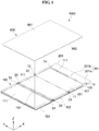
- FIG. 1 is a perspective view illustrating an exemplary embodiment of a display device
- FIG. 2 is a view illustrating a front surface of FIG. 1
- FIG. 3 is a view illustrating a rear surface of FIG. 1 .
- a display device 1000 in an exemplary embodiment may include a panel support portion 100, a display panel 900, and a first protection portion 201, as illustrated in FIGS. 1 to 3 .
- the panel support portion 100 may include a plurality of support portions 101, 102, and 103 and a plurality of hinge portions 151 and 152.
- the panel support portion 100 may further include a support surface 111 and a protrusion 120 disposed at an edge of the support surface 111.
- the protrusion 120 may protrude along a Z-axis direction from the edge of the support surface 111.
- a height of the protrusion 120 is higher than a height of the support surface 111.
- the height of the protrusion 120 and the height of the support surface 111 refer to the lengths in the Z-axis direction.
- the plurality of support portions 101, 102, and 103 may include a first support portion 101, a second support portion 102, and a third support portion 103. As illustrated in FIG. 1 , when the panel support portion 100 is fully unfolded, the second support portion 102 may be disposed between the first support portion 101 and the third support portion 103.
- the protrusion 120 on the first support portion 101 is not connected to the protrusion 120 on the second support portion 102 and the protrusion 120 on the third support portion 103
- the protrusion 120 on the second support portion 102 is not connected to the protrusion 120 on the first support portion 101 and the protrusion 120 on the third support portion 103
- the protrusion 120 on the third support portion 103 is not connected to the protrusion 120 on the first support portion 101 and the protrusion 120 on the second support portion 102.
- the protrusions 120 on different support portions are separated from each other.
- the protrusion 120 on the first support portion 101 may have a shape similar to "]"
- the protrusion 120 on the third support portion 103 may have a shape similar to "[”.
- the protrusion 120 on the first support portion 101 may include upper and lower portions extending in the X direction and facing each other and a right side portion connecting the upper and lower portions
- the protrusion 120 on the second support portion 102 may include upper and lower portions extending in the X direction and facing each other
- the protrusion 120 on the third support portion 103 may include upper and lower portions extending in the X direction and facing each other and a left side portion connecting the upper and lower portions.
- Adjacent ones of the support portions 101, 102, and 103 are rotatably connected to each other. To this end, the adjacent ones of the support portions 101, 102, and 103 may be hingedly coupled to each other by hinge portions 151 and 152 disposed therebetween.
- the plurality of hinge portions 151 and 152 may include a first hinge portion 151 and a second hinge portion 152.
- the number of hinge portions may be one less than the number of support portions.
- the panel support portion 100 may include two hinge portions, for example.
- the hinge portions 151 and 152 may be disposed between adjacent ones of the support portions 101, 102 and 103.
- the first hinge portion 151 may be disposed between the first support portion 101 and the second support portion 102 disposed adjacent to each other
- the second hinge portion 152 may be disposed between the second support portion 102 and the third support portion 103 adjacent to each other, for example.
- the first support portion 101 is connected to the first hinge portion 151
- the second support portion 102 is connected to the first hinge portion 151 and the second hinge portion 152
- the third support portion 103 is connected to the second hinge portion 152.
- a first connection portion 11 and a second connection portion 12 of the first support portion 101 are rotatably connected to the first hinge portion 151
- a first connection portion 21 and a second connection portion 22 of the second support portion 102 are rotatably connected to the first hinge portion 151
- a third connection portion 23 and a fourth connection portion 24 of the second support portion 102 are rotatably connected to the second hinge portion 152
- a first connection portion 31 and a second connection portion 32 of the third support portion 103 are rotatably connected to the second hinge portion 152, for example.
- the first, second, and third support portions 101, 102, and 103 may rotate by a predetermined angle with reference to the first and second hinge portions 151 and 152.
- the first support portion 101 may rotate about 180 degrees with respect to the first hinge portion 151 as an axis
- the third support portion 103 may rotate about 360 degrees with respect to the second hinge portion 152 as an axis, for example.
- the first support portion 101 is rotatable toward the support surface 111 of the second support portion 102.
- the first support portion 101 is in-foldable toward the support surface 111 of the second support portion 102.
- the second support portion 102 may not be able to rotate toward a rear surface 112 of the first support portion 101.
- the second support portion 102 may be rotatable toward a rear surface 112 of the third support portion 103.
- the third support portion 103 is rotatable toward the support surface 111 of the second support portion 102 or a rear surface 112 of the second support portion 102.
- the third support portion 103 is in-foldable toward the support surface 111 of the second support portion 102 and is also out-foldable toward the rear surface 112 of the second support portion 102.
- a rotation shaft of the first hinge portion 151 and a rotation shaft of the second hinge portion 152 may be substantially parallel to each other.
- a rotation shaft of the first protection portion 201 may be substantially parallel to at least one of the rotation shaft of the first hinge portion 151 and the rotation shaft of the second hinge portion 152.
- the display panel 900 is disposed on the panel support portion 100.
- the display panel 900 may be disposed on the support surface 111 of the panel support portion 100, for example. More specifically, the display panel 900 may be disposed on the respective support surfaces 111 of the first support portion 101, the second support portion 102, and the third support portion 103.
- a non-display surface 992 of the display panel 900 may contact respective support surfaces 111 of the first support portion 101, the second support portion 102, and the third support portion 103.
- the display panel 900 may also be disposed on the first hinge portion 151 and the second hinge portion 152, and in such an exemplary embodiment, the non-display surface 992 of the display panel 900 may contact the first hinge portion 151 and the second hinge portion 152. In an exemplary embodiment, the non-display surface 992 of the display panel 900 does not contact the first protection portion 201.
- the support surface 111 of the panel support portion 100 faces the non-display surface 992 of the display panel 900.
- the non-display surface 992 of the display panel 900 faces a display surface 991 of the display panel 900.
- the display panel 900 provides an image through the display surface 991.
- the non-display surface 992 of the display panel 900 may be disposed between the display surface 991 of the display panel 900 and the support surface 111 of the panel support portion 100.
- the display panel 900 disposed on the support surface 111 of the panel support portion 100 may be enclosed by the protrusion 120 of the panel support portion 100.
- the display panel 900 may be a flexible display panel 900 or a foldable display panel 900.
- the display panel 900 may be a light emitting display panel 900 or a liquid crystal display panel 900.
- the light emitting display panel 900 may be an organic light emitting diode (“OLED”) display panel 900.
- the first protection portion 201 may be connected to any one of the plurality of support portions 101, 102, and 103.
- the first protection portion 201 when the panel support portion 100 is fully unfolded as illustrated in FIGS. 1 and 2 , the first protection portion 201 may be connected to the first support portion 101 which is disposed at one outermost position of the panel support portion 100 of the plurality of support portions 101, 102, and 103, for example.
- the first protection portion 201 may be rotatably connected to the first support portion 101.
- the first protection portion 201 may be rotatably connected to the second side surface of the first support portion 101, for example.
- the first support portion 101 may include a third connection portion 13 and a fourth connection portion 14 which protrude from the second side surface of the first support portion 101 toward the first protection portion 201.
- the first protection portion 201 may be connected to the third connection portion 13 and the fourth connection portion 14 through a connection shaft 301.
- the third connection portion 13 and the fourth connection portion 14 have through holes 1 and 2, respectively.
- a through hole 1 of the third connection portion 13 and a through hole 2 of the fourth connection portion 14 may face each other in a Y-axis direction.
- the through hole 1 of the third connection portion 13 penetrates the third connection portion 13 in the Y-axis direction, and the through hole 2 of the fourth connection portion 14 penetrates the fourth connection portion 14 in the Y-axis direction.
- the first protection portion 201 may include, for example, a protection plate 201a and an extension portion 201b extending from the protection plate 201a.
- the extension portion 201b may be disposed between the third connection portion 13 and the fourth connection portion 14.
- the extension portion 201b of the first protection portion 201 has a through hole 3.
- the through hole 3 penetrates the extension portion 201b in the Y-axis direction.
- the connection shaft 301 described above is inserted into the through hole 1 of the third connection portion 13, the through hole 2 of the first protection portion 201, and the through hole 2 of the fourth connection portion 14.
- the first protection portion 201 is rotatably coupled to the connection shaft 301.
- the first protection portion 201 may include, for example, a transparent material.
- the first protection portion 201 may protect the second hinge portion 152 and a display panel portion (e.g., a second curved portion (900b in FIG. 11 ) of the display panel) on the second hinge portion 152. Detailed description thereof will be described below.
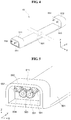
- FIG. 4 is a perspective view illustrating the first hinge portion 151 of FIG. 1
- FIG. 5 is a detailed configuration view illustrating the first hinge portion 151 of FIG. 4 .
- the first hinge portion 151 may include a first plate 501, a first coupling portion 511, and a second coupling portion 512.
- the first coupling portion 511 may protrude in the Z-axis direction from one edge of the first plate 501.
- the first support portion 101 and the second support portion 102 described above, may be rotatably connected to the first coupling portion 511.
- the first connection portion 11 of the first support portion 101 and the first connection portion 21 of the second support portion 102 may be rotatably connected to the first coupling portion 511, for example.
- the first coupling portion 511 may include a first rotation shaft 551 and a second rotation shaft 552.
- the first rotation shaft 551 and the second rotation shaft 552 extend along a Y-axis direction.
- the first rotation shaft 551 and the second rotation shaft 552 are exposed to the outside of the first coupling portion 511 through holes of the first coupling portion 511, respectively.
- the first rotation shaft 551 and the second rotation shaft 552 are exposed to the outside through opposite surfaces of the first coupling portion 511 that face each other in the Y-axis direction.
- the first rotation shaft 551 is connected to the first connection portion 11 of the first support portion 101.
- the first rotation shaft 551 may be inserted into a coupling hole of the first connection portion 11 of the first support portion 101, for example.
- an end portion of the first rotation shaft 551 and the coupling hole of the first connection portion 11 connected to the end portion may each have a quadrangular shape, for example.
- the second rotation shaft 552 is connected to the first connection portion 21 of the second support portion 102.
- the second rotation shaft 552 may be inserted into a coupling hole of the first connection portion 21 of the second support portion 102, for example.
- an end portion of the second rotation shaft 552 and the coupling hole of the first connection portion 21 connected to the end portion may each have a quadrangular shape.
- the first coupling portion 511 may include a first gear 591, a second gear 592, a third gear 593, and a fourth gear 594.
- the first gear 591, the second gear 592, the third gear 593, and the fourth gear 594 may be disposed at an accommodation space provided in the first coupling portion 511.
- the first gear 591 and the second gear 592 are spaced apart from each other at an upper position of the accommodation space, and the third gear 593 and the fourth gear 594 are disposed at a lower position of the accommodation space.
- the third gear 593 is disposed below the first gear 591
- the fourth gear 594 is disposed below the second gear 592.
- a shaft of the first gear 591 may be connected to the first rotation shaft 551 described above, and a shaft of the second gear 592 may be connected to the second rotation shaft 552 described above.
- the shaft of the first gear 591 may be unitary with the first rotation shaft 551
- the shaft of the second gear 592 may be unitary with the second rotation shaft 552, for example.
- the first gear 591 is connected to the third gear 593, the third gear 593 is connected to the fourth gear 594, and the fourth gear 594 is connected to the second gear 592.
- the first gear 591 is engagingly connected to the third gear 593
- the third gear 593 is engagingly connected to the fourth gear 594
- the fourth gear 594 is engagingly connected to the second gear 592.
- each of the shaft of the third gear 593 and the shaft of the fourth gear 594 is rotatably coupled to the first coupling portion 511.
- the second coupling portion 512 may protrude in the Z-axis direction from another edge of the first plate 501.
- the first support portion 101 and the second support portion 102 described above may be rotatably connected to the second coupling portion 512.
- the second connection portion 12 of the first support portion 101 and the second connection portion 22 of the second support portion 102 may be rotatably connected to the second coupling portion 512, for example.
- the second coupling portion 512 may include a third rotation shaft 553 and a fourth rotation shaft 554.
- the third rotation shaft 553 and the fourth rotation shaft 554 extend along the Y-axis direction.
- the third rotation shaft 553 and the fourth rotation shaft 554 are exposed to the outside of the second coupling portion 512 through holes of the second coupling portion 512, respectively.
- the third rotation shaft 553 and the fourth rotation shaft 554 are exposed to the outside through opposite surfaces of the second coupling portion 512 that face each other in the Y-axis direction.
- the third rotation shaft 553 is connected to the second connection portion 12 of the first support portion 101.
- the third rotation shaft 553 may be inserted into a coupling hole of the second connection portion 12 of the first support portion 101, for example.
- an end portion of the third rotation shaft 553 and the coupling hole of the second connection portion 12 connected to the end portion may each have a quadrangular shape.
- the fourth rotation shaft 554 is connected to the second connection portion 22 of the second support portion 102.
- the fourth rotation shaft 554 may be inserted into a coupling hole of the second connection portion 22 of the second support portion 102, for example.
- an end portion of the fourth rotation shaft 554 and the coupling hole of the second connection portion 22 connected to the end portion may each have a quadrangular shape.
- the second coupling portion 512 may include the first, second, third, and fourth gears 591, 592, 593, and 594 described above.
- a shaft of the first gear 591 included in the second coupling portion 512 may be connected to the third rotation shaft 553, and a shaft of the second gear 592 included in the second coupling portion 512 may be connected to the fourth rotation shaft 554.
- FIG. 6 is a perspective view illustrating the second hinge portion 152 of FIG. 1
- FIG. 7 is a view illustrating a coupling relationship between the second hinge portion 152 and the support portions of FIG. 6
- FIG. 8 is a perspective view illustrating one of joint portions 600 of FIG. 6
- FIG. 9 is an explanatory view illustrating a connection relationship between the joint portions 600 and the connection shaft.
- the second hinge portion 152 may include a plurality of joint portions 600, a plurality of first connection shafts 621, and a plurality of second connection shafts 622.
- Each of the joint portions 600 may include a second plate 602, a third coupling portion 613, and a fourth coupling portion 614.
- the third coupling portion 613 is connected to one edge of the second plate 602, and the fourth coupling portion 614 is connected to another edge of the second plate 602.
- the second plate 602, the third coupling portion 613, and the fourth coupling portion 614 included in one joint portion 600 may be provided unitarily.
- Adjacent ones of the third coupling portions 613 are hingedly coupled to each other through the first connection shafts 621.
- each of the plurality of third coupling portions 613 may have a cross-section in a rhombus shape.
- At least one first protrusion 61 and at least one first recess 71 are alternately disposed on one surface of each of the third coupling portions 613, and at least one second protrusion 62 and at least one second recess 72 are alternately disposed on another surface of each of the third coupling portion 613.
- the second recess 72 is disposed at a position corresponding to the first protrusion 61
- the second protrusion 62 is disposed at a position corresponding to the first recess 71.
- the first protrusion 61 and the second protrusion 62 have through hole 60 penetrating respective center portion of the first protrusion 61 and the second protrusion 62.
- first protrusion 61 and the second protrusion 62 each have a shape of a protruding cylinder, and the first recess 71 and the second recess 72 each have a concave shape.
- the first protrusion 61 provided at one of facing surfaces of the third coupling portions 613 adjacent to each other faces the second recess 72 provided at the other of the facing surfaces. This first protrusion 61 is inserted into the second recess 72. After the protrusions and the recesses of the third coupling portions 613 adjacent to each other are coupled to each other, the first connection shaft 621 is inserted into the holes of the protrusions. In such a manner, the third coupling portions 613 adjacent to each other may be coupled in a hinged manner.
- the third coupling portion 613 disposed at one outermost position of the plurality of third coupling portions 613 is connected to the third connection portion 23 of the second support portion 102 through the first connection shaft 621, and the third coupling portion 613 disposed at another outermost position of the plurality of third coupling portions 613 is connected to the first connection portion 31 of the third support portion 103 through the first connection shaft 621.
- the third coupling portion 613 disposed at the one outermost position of the plurality of third coupling portions 613 is disposed most adjacent to the second support portion 102 among the plurality of third coupling portions 613, and the third coupling portion 613 disposed at the another outermost position of the plurality of third coupling portions 613 is disposed most adjacent to the third support portion 103 among the plurality of third coupling portions 613.
- each of the plurality of fourth coupling portions 614 may have a cross-section in a rhombus shape.
- the fourth coupling portion 614 may include or have the first protrusion 61, the second protrusion 62, the first recess 71, and the second recess 72 described above. Specifically, at least one first protrusion and at least one first recess are alternately disposed on one surface of each of the fourth coupling portions 614, and at least one second protrusion and at least one second recess are alternately disposed on another surface of each of the fourth coupling portions 614.
- the second recess is disposed at a position corresponding to the first protrusion, and the second protrusion is disposed at a position corresponding to the first recess.
- the first and second protrusions each have a shape of a protruding cylinder, and the first and second recesses have a concave shape.
- the first protrusion provided at one of facing surfaces of the fourth coupling portions 614 adjacent to each other faces the second recess provided at the other surface of the facing surfaces. This first protrusion is inserted into the second recess. After the protrusions and the recesses of the fourth coupling portions 614 adjacent to each other are coupled to each other, the second connection shaft 622 is inserted into the holes of the protrusions. In such a manner, the fourth coupling portions 614 adjacent to each other may be coupled in a hinged manner.
- the fourth coupling portion 614 disposed at one outermost position of the plurality of fourth coupling portions 614 is connected to the fourth connection portion 24 of the second support portion 102 through the second connection shaft 622, and the fourth coupling portion 614 disposed at another outermost position of the plurality of fourth coupling portions 614 is connected to the second connection portion 32 of the third support portion 103 through the second connection shaft 622.
- the fourth coupling portion 614 disposed at the one outermost position of the plurality of fourth coupling portions 614 is disposed most adjacent to the second support portion 102 among the plurality of fourth coupling portions 614, and the fourth coupling portion 614 disposed at the another outermost position of the plurality of fourth coupling portions 614 is disposed most adjacent to the third support portion 103 among the plurality of fourth coupling portions 614.
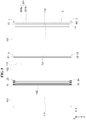
- FIG. 10 is a view illustrating the display device of FIG. 1 viewed in the direction of an arrow in a Y-axis direction
- FIG. 11 is a view illustrating a folded state of the display device of FIG. 10 .
- the first protection portion 201 and the first support portion 101 may define a predetermined angle ⁇ 1.
- the angle ⁇ 1 between the first protection portion 201 and the first support portion 101 may be in a range from about 90 degrees to about 180 degrees, for example.
- an angle defined between an inner side surface 201c of the first protection portion 201 and the support surface 111 of the first support portion 101 may be in a range from about 90 degrees to about 180 degrees
- the angle ⁇ 1 between the first protection portion 201 and the first support portion 101 may be in a range from about 80 degrees to about 190 degrees.
- the support portions 101, 102, and 103 may be disposed along the Z-axis direction (e.g., the vertical direction), as illustrated in FIG. 11 .
- the second support portion 102 may be disposed on the first support portion 101
- the third support portion 103 may be disposed on the second support portion 102.
- the support surface 111 of the first support portion 101 and the support surface 111 of the second support portion 102 may face each other, and the rear surface 112 of the second support portion 102 and the rear surface 112 of the third support portion 103 may face each other.
- the display panel 900 on the panel support portion 100 is also kept in the folded state.
- a display panel portion on the first hinge portion 151 and a display panel portion on the second hinge portion 152 are curved, for example.
- the first curved portion 900a of the display panel 900 is disposed on the first hinge portion 151
- the second curved portion 900b of the display panel 900 is disposed on the second hinge portion 152.
- the first protection portion 201 may rotate 90 degrees toward the support surface 111 of the first support portion 101.
- the first protection portion 201 is disposed in a perpendicular direction with respect to the support surface 111 of the first support portion 101.
- the first protection portion 201 may have a shape protruding along the Z-axis direction.
- the first protection portion 201 protruding in the Z-axis direction faces the second hinge portion 152 and the second curved portion 900b of the display panel 900 in the X-axis direction. Accordingly, the second hinge portion 152 and the second curved portion 900b of the display panel 900 may be disposed between a side surface of the panel support portion 100 (e.g., a side surface of the third support portion 103 and a side surface of the second support portion 102) and the first protection portion 201. Accordingly, the second hinge portion 152 and the second curved portion 900b of the display panel 900 may be protected by the first protection portion 201.
- an angle between the first protection portion 201 and the first support portion 101 may be fixed at about 90 degrees.
- the first protection portion 201 may be connected to the first support portion 101 in a fixed state.
- the first protection portion 201 may have a shape protruding from one edge of the first support portion 101, for example.
- FIG. 12 is a view illustrating another exemplary embodiment of the display device 1000
- FIG. 13 is an explanatory view illustrating an exemplary embodiment of the buffer portion 400 of FIG. 12
- FIG. 14 is an explanatory view illustrating another exemplary embodiment of the buffer portion 400 of FIG. 12 .
- the display device 1000 in an exemplary embodiment may further include a buffer portion 400 disposed at the inner side surface 201c of the first protection portion 201.
- the buffer portion 400 may be disposed over an entire surface of the inner side surface 201c of the protection plate 201a.
- the buffer portion 400 may be disposed at each of opposite edges of the inner side surface 201c of the protection plate 201a, as illustrated in FIG. 14 .
- the buffer portions 400 disposed at the opposite edges of the inner side surface 201c of the protection plate 201 a do not overlap the display panel 900.
- the buffer portion 400 may include at least one of acryl, silicone, and rubber, for example.
- FIG. 15 is a view illustrating another exemplary embodiment of the first protection portion 201 of the display device 1000.
- the display device 1000 in an exemplary embodiment may further include an auxiliary display panel 110 disposed at the inner side surface 201c of the first protection portion 201.
- icons 115 related to various functions such as a call, a message, a phone book, the internet, a clock, a camera, a volume control, and the like may be displayed.
- the aforementioned auxiliary display panel 110 may be disposed at an outer side surface 201d, instead of the inner side surface 201c, of the first protection portion 201. In an alternative exemplary embodiment, the aforementioned auxiliary display panel 110 may be disposed on both the inner side surface 201c and the outer side surface 201 d of the first protection portion 201.
- FIG. 16 is a view illustrating another exemplary embodiment of the first protection portion 201 of the display device 1000
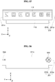
- FIGS. 17 and 18 are explanatory views illustrating an operation of a mode determination sensor 510 of FIG. 16 .
- the display device 1000 in an exemplary embodiment may include at least one of a mode determination sensor 510 and a fingerprint sensor 520 disposed at the inner side surface 201c of the first protection portion 201.
- the mode determination sensor 510 may detect whether the display device 1000 is folded. In an exemplary embodiment, when the display device 1000 is fully unfolded as illustrated in FIG. 17 , for example, light from the mode determination sensor 510 is not blocked, and in such a case, the mode determination sensor 510 determines that the display device 1000 is in an unfolding mode. When the display device 1000 is completely folded as illustrated in FIG. 18 , light from the mode determination sensor 510 is blocked by the second hinge portion 152, and in such a case, the mode determination sensor 510 determines that the display device 1000 is in a folding mode.
- the mode determination sensor 510 described above may be disposed at an edge of the first protection portion 201 so that the light from the mode determination sensor 510 may be substantially prevented from being blocked by a user's finger or the like.
- the edge of the first protection portion 201 corresponds to one edge of the second hinge portion 152.
- the mode determination sensor 510 may include an infrared sensor, for example.
- the detection result from the mode determination sensor 510 may be displayed on the display panel 900.
- a text such as "unfolding mode” may be displayed on the display panel 900, for example.
- a text such as "folding mode” may be displayed on the display panel 900.
- Such text may be displayed on the display surface 991 991 of the auxiliary display panel 110 described above.
- the fingerprint sensor 520 detects a fingerprint in contact with the fingerprint sensor 520.
- a driver of the display device 1000 may compare the detected fingerprint with a pre-registered fingerprint, and limit the use authority of the display device 1000 according to the comparison result.
- the display surface 991 of the display panel 900 may be activated, for example.
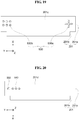
- FIG. 19 is a view illustrating another exemplary embodiment of the first protection portion 201 of the display device 1000.
- the display device 1000 in an exemplary embodiment may include a physical manipulation unit 530 disposed at the inner side surface 201c of the first protection portion 201.
- the physical manipulation unit 530 may include, for example, a direction control key 530a in a cross-like shape, and a push button 530b.
- the screen of the display panel 900 may be controlled by manipulating the physical manipulation unit 530.
- the physical manipulation unit 530 may be disposed at an outer side surface 201d of the first protection portion 201.
- FIG. 20 is a view illustrating another exemplary embodiment of the first protection portion 201 of the display device 1000.
- the display device 1000 in an exemplary embodiment may include at least one of an imaging unit 540 and a lighting unit 550 disposed at the outer side surface 201 d of the first protection portion 201.
- the imaging unit 540 may include a camera. An image captured by the imaging unit 540 may be displayed on the display panel 900.
- the lighting unit 550 emits light.
- the lighting unit 550 may emit light in synchronization with a capturing time of the imaging unit 540.
- the lighting unit 550 may be driven independently regardless of whether the imaging unit 540 is capturing images.
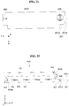
- FIG. 21 is a view illustrating another exemplary embodiment of the first protection portion 201 of the display device 1000
- FIGS. 22 and 23 are explanatory views illustrating an operation of a position determination sensor 560 of FIG. 21 .
- the display device 1000 in an exemplary embodiment includes at least one of a position determination sensor 560 and a fingerprint sensor 570 disposed on the outer side surface 201d of the first protection portion 201.
- the position determination sensor 560 may determine a position of the first protection portion 201. In an exemplary embodiment, as illustrated in FIG. 22 , when the first protection portion 201 defines an angle of about 180 degrees with the first support portion 101, the position determination sensor 560 detects this angle and transmits the detection result to the driver of the display device 1000, for example. In such an exemplary embodiment, the driver may control the display panel 900 to display, on the display panel 900, the angle between the first protection portion 201 and the first support portion 101. In an exemplary embodiment, when the first protection portion 201 defines an angle of about 90 degrees with the first support portion 101 as illustrated in FIG. 23 , the position determination sensor 560 detects the angle and transmits the detection result to the driver of the display device 1000. In such an exemplary embodiment, the driver may control the display panel 900 to display, on the display panel 900, the angle between the first protection portion 201 and the first support portion 101.
- the fingerprint sensor 570 detects a fingerprint in contact with the fingerprint sensor 570. Since the fingerprint sensor 570 is substantially the same as the fingerprint sensor 520 of FIG. 16 , the description of the fingerprint sensor 570 of FIG. 21 will refer to the description of the fingerprint sensor 520 of FIG. 16 .
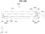
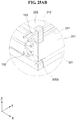
- FIGS. 24A and 24B are explanatory views illustrating another exemplary embodiment of the first protection portion 201.
- the first protection portion 201 may have a thickness which gradually increases, as further away from the third support portion 103.
- the first protection portion 201 may further include a protrusion 201e protruding from the protection plate 201a.
- the protrusion 201 e may protrude from one edge of the protection plate 201a.
- an inner side surface 201f of the protrusion 201e may have a round shape, for example.
- a curvature of the protrusion 201e and a curvature of the second curved portion 900b of the display panel 900 may be substantially the same as each other.
- At least one of the buffer portion 400, the auxiliary display panel 110, the mode determination sensor 510, the fingerprint sensor 520, and the physical manipulation unit 530 described above may be disposed at the inner side surface 201c of the first protection portion 201 of FIGS. 24A and 24B .
- at least one of the imaging unit 540, the lighting unit 550, the position determination sensor 560, and the fingerprint sensor 570 described above may be disposed on the outer side surface 201d of the first protection portion 201 of FIGS. 24A and 24B .
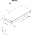
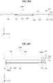
- FIGS. 25AA to 25C are views illustrating another exemplary embodiment of the display device 1000.
- the display device 1000 in another exemplary embodiment may further include a second protection portion 202, as illustrated in FIGS. 25AA to 25C .
- the second protection portion 202 is rotatably connected to the first protection portion 201.
- the second protection portion 202 may be connected to the first protection portion 201 through a third hinge portion 153, for example.
- the second protection portion 202 may rotate 360 degrees with reference to the third hinge portion 153.
- One end portion of the third hinge portion 153 may be rotatably connected to the first protection portion 201 through a first connection shaft 311, and another end portion of the third hinge portion 153 may be connected to the second protection portion 202 through a second connection shaft 312.
- a rotation shaft of the second protection portion 202 may be substantially parallel to at least one of a rotation shaft of the first hinge portion 151 and a rotation shaft of the second hinge portion 152.
- the second protection portion 202 may rotate in a counterclockwise direction to be disposed on the third support portion 103.
- the second protection portion 202 faces the display surface 991 of the display panel 900 disposed on the support surface 111 on the third support portion 103.
- the display panel 900 on the support surface 111 may be protected by the second protection portion 202.
- the display surface 991 (refer to FIG. 1 ) of the display panel 900 on the support surface 111 may be protected by the second protection portion 202, for example.
- the second protection portion 202 may include a transparent material or a translucent material.
- the second protection portion 202 when the second protection portion 202 is disposed on the third support portion 103, the second protection portion 202 may contact the display panel 900 on the third support portion 103. In other words, the second protection portion 202 may contact the display surface 991 of the display panel 900.
- a touch applied from the outside to the second protection portion 202 may be recognized by a touch sensing unit of the display panel 900.
- At least one of the buffer portion 400, the auxiliary display panel 110, the mode determination sensor 510, the fingerprint sensor 520, and the physical manipulation unit 530 described above may be disposed at the inner side surface 201c of the first protection portion 201 of FIGS. 25AA to 25C .
- at least one of the imaging unit 540, the lighting unit 550, the position determination sensor 560, and the fingerprint sensor 570 described above may be disposed on the outer side surface 201 d of the first protection portion 201 of FIGS. 25AA to 25C .
- first protection portion 201 of FIGS. 25AA to 25C may have a shape substantially the same as a shape of the first protection portion 201 of FIGS. 24AA and 24B described above.
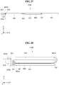
- FIG. 26 is a view illustrating another exemplary embodiment of the display device 1000
- FIG. 27 is a view illustrating the display device 1000 of FIG. 26 viewed in the direction of an arrow in the Y-axis direction
- FIG. 28 is a view illustrating a folded state of the display device 1000 of FIG. 27 .
- the display device 1000 in an exemplary embodiment may include a third protection portion 203.
- the third protection portion 203 may be connected to the third support portion 103 disposed at another outermost position of the panel support portion 100 among the plurality of support portions 101, 102 and 103.
- the third protection portion 203 may be rotatably connected to the third support portion 103.
- one surface of the third support portion 103, connected to the second hinge portion 152 is defined as a first side surface
- another surface of the third support portion 103 that faces the first side surface of the third support portion 103 is defined as a second side surface
- the third protection portion 203 may be rotatably connected to the second side surface of the third support portion 103, for example.
- the third support portion 103 may include a third connection portion 33 and a fourth connection portion 34 protruding from the second side surface of the third support portion 103 toward the third protection portion 203.
- the third protection portion 203 may be connected to the third connection portion 33 and the fourth connection portion 34 through a connection shaft 303.
- the third connection portion 33 and the fourth connection portion 34 have through holes 10 and 20, respectively.
- the through hole 10 of the third connection portion 33 and the through hole 20 of the fourth connection portion 34 may face each other in the Y-axis direction.
- the through hole 10 of the third connection portion 33 penetrates the third connection portion 33 in the Y-axis direction, and the through hole 20 of the fourth connection portion 34 penetrates the fourth connection portion 34 in the Y-axis direction.
- the third protection portion 203 may include, for example, a protection plate 203a and an extension portion 203b extending from the protection plate 203a.
- the extension portion 203b may be disposed between the third connection portion 33 and the fourth connection portion 34.
- the extension portion 203b of the third protection portion 203 has a through hole 30.
- the through hole 30 of the third protection portion 203 penetrates the extension portion 203b in the Y-axis direction.
- the aforementioned connection shaft 303 is inserted into the through hole 10 of the third connection portion 33, the through hole 30 of the third protection portion 203, and the through hole 20 of the fourth connection portion 34.
- the third protection portion 203 is rotatably coupled to the connection shaft 303.
- the third protection portion 203 may include, for example, a transparent material.
- the third protection portion 203 may protect the first hinge portion 151 and the display panel portion (e.g., the first curved portion 900a of the display panel 900) on the first hinge portion 151.
- the third protection portion 203 and the third support portion 103 may define a predetermined angle ⁇ 3.
- the angle ⁇ 3 between the third protection portion 203 and the third support portion 103 may be in a range from about 90 degrees to about 180 degrees, for example.
- the angle ⁇ 3 defined between the inner side surface 203c of the third protection portion 203 and the rear surface 112 of the third support portion 103 may be in a range from about 90 degrees to about 180 degrees.
- the angle ⁇ 3 between the third protection portion 203 and the third support portion 103 may be in a range from about 80 degrees to about 190 degrees.
- a rotation shaft of the third protection portion 203 may be substantially parallel to at least one of a rotation shaft of the first hinge portion 151 and a rotation shaft of the second hinge portion 152.
- the support portions 101, 102, and 103 may be disposed along the Z-axis direction (e.g., the vertical direction), as illustrated in FIG. 28 .
- the second support portion 102 may be disposed on the first support portion 101
- the third support portion 103 may be disposed on the second support portion 102.
- the support surface 111 of the first support portion 101 and the support surface 111 of the second support portion 102 may face each other, and the rear surface 112 of the second support portion 102 and the rear surface 112 of the third support portion 103 may face each other.
- the display panel 900 on the panel support portion 100 is also kept in the folded state.
- the display panel portion on the first hinge portion 151 and the display panel portion on the second hinge portion 152 are curved, for example.
- the first curved portion 900a of the display panel 900 is disposed on the first hinge portion 151
- the second curved portion 900b of the display panel 900 is disposed on the second hinge portion 152.
- the third protection portion 203 may rotate 90 degrees toward the rear surface 112 of the third support portion 103.
- the third protection portion 203 is disposed in a perpendicular direction with respect to the rear surface 112 of the third support portion 103.
- the third protection portion 203 may have a shape protruding along a direction opposite to the Z-axis direction (hereinafter, a "-Z-axis direction").
- the third protection portion 203 protruding in the -Z-axis direction faces the first hinge portion 151 and the first curved portion 900a of the display panel 900 in the X-axis direction. Accordingly, the first hinge portion 151 and the first curved portion 900a of the display panel 900 may be disposed between a side surface of the panel support portion 100 (e.g., a side surface of the second support portion 102 and a side surface of the first support portion 101) and the third protection portion 203. Accordingly, the first hinge portion 151 and the first curved portion 900a of the display panel 900 may be protected by the third protection portion 203.
- At least one of the buffer portion 400, the auxiliary display panel 110, the mode determination sensor 510, the fingerprint sensor 520, and the physical manipulation unit 530 described above may be disposed at the inner side surface 203c of the third protection portion 203.
- at least one of the imaging unit 540, the lighting unit 550, the position determination sensor 560, and the fingerprint sensor 520 described above may be disposed at an outer side surface 203d of the third protection portion 203.
- at least one of the buffer portion 400, the auxiliary display panel 110, the mode determination sensor 510, the fingerprint sensor 520, and the physical manipulation unit 530 described above may be disposed at the outer side surface 203d of the third protection portion 203.
- at least one of the imaging unit 540, the lighting unit 550, the position determination sensor 560, and the fingerprint sensor 520 described above may be disposed at the inner side surface 203c of the third protection portion 203.
- the third protection portion 203 may have a shape substantially the same as a shape of the first protection portion 201 of FIGS. 24AA and 24B described above.
- the angle between the third protection portion 203 and the third support portion 103 may be fixed at about 90 degrees.
- the third protection portion 203 may be connected to the third support portion 103 in a fixed state.
- the third protection portion 203 may have a shape protruding from one edge of the third support portion 103, for example.
- FIG. 29 is a view illustrating another exemplary embodiment of the display device 1000.
- the display device 1000 may include the first protection portion 201 and the third protection portion 203 described above.
- first protection portion 201 and the third protection portion 203 of FIG. 29 are substantially the same as the first protection portion 201 of FIG. 1 and the third protection portion 203 of FIG. 26 , respectively, the description of the first protection portion 201 of FIG. 29 will refer to the description on the first protection portion 201 of FIG. 1 , and the description of the third protection portion 203 of FIG. 29 will refer to the description on the third protection portion 203 of FIG. 26 .
- FIG. 30 is a view illustrating another exemplary embodiment of the display device 1000.
- the display device 1000 may include the first protection portion 201 and the third protection portion 203 described above.
- the first protection portion 201 and the third protection portion 203 of FIG. 30 are substantially the same as the first protection portion 201 of FIG. 1 and the third protection portion 203 of FIG. 26 described above.
- the first protection portion 201 may contact the second hinge portion 152 and the display surface 991 of the display panel 900 disposed on the second hinge portion 152.
- the third protection portion 203 may contact the first hinge portion 151.
- FIG. 31 is a view illustrating another exemplary embodiment of a display device. Specifically, FIG. 31 illustrates another exemplary embodiment of the first protection portion.
- a first protection portion 241 includes a protection plate 70, a first extension portion 71, a second extension portion 72, a first rotation shaft 81, and a second rotation shaft 82.
- the first extension portion 71 extends in a -X-axis direction from one edge of the protection plate 70.
- the first extension portion 71 has a through hole 41 penetrating the first extension portion 71 in the Y-axis direction.
- the second extension portion 72 extends in the -X-axis direction from another edge of the protection plate 70.
- the second extension portion 72 has a through hole 42 penetrating the second extension portion 72 in the Y-axis direction.
- the first rotation shaft 81 passes through the through hole 41 of the first extension portion 71 and is coupled to a recess 91 of the first support portion 101.
- the recess 91 of the first support portion 101 is disposed at a third coupling portion 33 of the first support portion 101.
- the second rotation shaft 82 passes through the through hole 42 of the second extension portion 72 and is coupled to a recess 92 of the first support portion 101.
- the recess 92 of the first support portion 101 is disposed at a fourth coupling portion 34 of the first support portion 101.
- the display device according to one or more exemplary embodiments provides the following effects.
- the display device includes a protection portion connected to a panel support portion.
- the protection portion may protect the curved portion of the display panel that is folded. Accordingly, damage to the display panel may be substantially prevented.
Landscapes
- Engineering & Computer Science (AREA)
- Theoretical Computer Science (AREA)
- Physics & Mathematics (AREA)
- General Physics & Mathematics (AREA)
- Computer Hardware Design (AREA)
- General Engineering & Computer Science (AREA)
- Human Computer Interaction (AREA)
- Mechanical Engineering (AREA)
- Devices For Indicating Variable Information By Combining Individual Elements (AREA)
- Casings For Electric Apparatus (AREA)
- Pivots And Pivotal Connections (AREA)
Abstract
Description
- Exemplary embodiments of the invention relate to a display device, and more particularly, to a display device capable of substantially preventing damage to a display panel.
- A deformable display device such as a flexible or foldable display device generally includes a display panel that may be bendable. Since a curved portion of a display panel is more stressed than other portions thereof, the curved portion may be vulnerable to an impact from an outside.
- Exemplary embodiments of the invention may be directed to a display device capable of substantially preventing damage to a display panel.
- An exemplary embodiment provides a display device including a panel support portion including a plurality of support portions rotatably connected to each other, a flexible display panel on a first surface of the panel support portion, and a first protection portion rotatably connected to a side of the panel support portion.
- In the present invention, the curved portion of the flexible display can be protected from the impact from the outside due to the first protection portion.
- In an exemplary embodiment, the first protection portion may be connected to the side of the panel support portion in a rotatable manner by a degree in a range from about 80 degrees to about 190 degrees. Then, the first protection portion could protrude to face a curved portion of the flexible display panel. The first protection portion is not exposed to an outside and can be protected from the impact from the outside due to the first protection portion.
- In an exemplary embodiment, the display device may include a rotation shaft in respect to which the first protection portion is rotated and through which the first protection portion is connected to the side of the panel support portion.
- In an exemplary embodiment, the rotation shaft of the first protection portion may be substantially parallel to a rotation shaft between the first support portion and the second support portion.
- In an exemplary embodiment, the first protection portion may not contact a non-display surface of the flexible display panel.
- In an exemplary embodiment, the panel support portion may further include a first support portion rotatably connected to the first protection portion, a second support portion rotatably connected to the first support portion, and a third support portion rotatably connected to the second support portion.
- In an exemplary embodiment, the first protection portion may be connected to the first support portion in a rotatable manner by a degree in a range from about 80 degrees to about 190 degrees, preferably in a range from about 90 degrees to about 180 degrees.
- In an exemplary embodiment, when an angle between the first protection portion and the first support portion is less than about 180 degrees, the first protection portion may face a display surface of the flexible display panel between the second support portion and the third support portion.
- In an exemplary embodiment, a rotation shaft of the first protection portion may be substantially parallel to a rotation shaft between the first support portion and the second support portion.
- In an exemplary embodiment, the first support portion and the second support portion may rotate such that a first surface of the first support portion and a second surface of the second support portion face each other.
- In an exemplary embodiment, the second support portion and the third support portion may rotate such that a second surface of the second support portion and a second surface of the third support portion face each other, or such that a first surface of the second support portion and a first surface of the third support portion face each other.
- In an exemplary embodiment, a first edge of first and second edges, facing each other, of the first support portion may be rotatably connected to the second support portion, and the second edge is rotatably connected to the first protection portion.
- In an exemplary embodiment, the first protection portion may extend along the second edge.
- In an exemplary embodiment, the first protection portion may have a thickness that increases, as further away from the first support portion.
- In an exemplary embodiment, a surface of the first support portion may have a rounded shape.
- In an exemplary embodiment, at least a part of a surface of the first protection portion may have a curvature substantially the same as a curvature of a curved portion of the flexible display panel.
- In an exemplary embodiment, when an angle between the first protection portion and the first support portion is about 90 degrees, the first protection portion may not expose a curved portion of the flexible display panel.
- In an exemplary embodiment, when an angle between the first protection portion and the first support portion is about 90 degrees, the first protection portion may contact a curved portion of the flexible display panel.
- In an exemplary embodiment, the first protection portion may include a protection plate, and an extension portion extending from the protection plate and disposed between a first connection portion and a second connection portion of the first support portion. The protection plate, the first connection portion and the second connection portion may be connected to each other by a rotation shaft.
- In an exemplary embodiment, the first protection portion may include a protection plate, a first extension portion extending from a first edge of the protection plate and disposed outside a first connection portion of the first support portion, and a second extension portion extending from a second edge of the protection plate and disposed outside a second connection portion of the first support portion. The protection plate and the first extension portion may be connected to each other by a first rotation shaft, and the protection plate and the second extension portion are connected to each other by a second rotation shaft.
- In an exemplary embodiment, the first protection portion may include a transparent material.
- In an exemplary embodiment, the display device may further include a buffer portion at an inner side surface of the first protection portion.
- In an exemplary embodiment, the buffer portion may be disposed over an entire surface of the inner side surface of the first protection portion.
- In an exemplary embodiment, the buffer portion may be disposed at opposite edges of the inner side surface of the first protection portion.
- In an exemplary embodiment, the display device may further include an auxiliary display panel on at least one of an inner side surface and an outer side surface of the first protection portion.
- In an exemplary embodiment, the display device may further include a mode determination sensor on at least one of an inner side surface and an outer side surface of the first protection portion.
- In an exemplary embodiment, the display device may further include a fingerprint sensor disposed on at least one of an inner side surface and an outer side surface of the first protection portion.
- In an exemplary embodiment, the display device may further include a physical manipulation unit on at least one of an inner side surface and an outer side surface of the first protection portion.
- In an exemplary embodiment, the display device may further include an imaging unit on at least one of an inner side surface and an outer side surface of the first protection portion.
- In an exemplary embodiment, the display device may further include a lighting unit on at least one of an inner side surface and an outer side surface of the first protection portion.
- In an exemplary embodiment, the display device may further include a second protection portion rotatably connected to the first protection portion.
- In an exemplary embodiment, the second protection portion may be disposed on the third support portion.
- In an exemplary embodiment, the second protection portion may include a transparent or translucent material.
- In an exemplary embodiment, the display device may further include a third protection portion rotatably connected to the third support portion.
- In an exemplary embodiment, an angle between an inner side surface of the third protection portion and a rear surface of the third support portion may be in a range from about 80 degrees to about 190 degrees.
- In an exemplary embodiment, the display device may further include a first hinge portion connecting the first support portion and the second support portion.
- In an exemplary embodiment, the first hinge portion may include a first plate, a first coupling portion protruding from a first edge of the first plate, and connected to a first connection portion of the first support portion and a first connection portion of the second support portion, and a second coupling portion protruding from a second edge of the first plate, and connected to a second connection portion of the first support portion and a second connection portion of the second support portion.
- In an exemplary embodiment, the first coupling portion may include a first rotation shaft connected to the first connection portion of the first support portion, a second rotation shaft connected to the first connection portion of the second support portion, and a plurality of gears connected to the first rotation shaft and the second rotation shaft.
- In an exemplary embodiment, the second coupling portion may include a third rotation shaft connected to the second connection portion of the first support portion, a fourth rotation shaft connected to the second connection portion of the second support portion, and a plurality of gears connected to the third rotation shaft and the fourth rotation shaft.
- In an exemplary embodiment, the display device may further include a second hinge portion connecting the second support portion and the third support portion.
- In an exemplary embodiment, the second hinge portion may include a plurality of joint portions hingedly coupled between the second support portion and the third support portion.
- An exemplary embodiment provides a display device including a panel support portion including a first support portion, a second support portion rotatably connected to the first support portion, and a third support portion rotatably connected to the second support portion, a flexible display panel on the panel support portion, and a protection portion rotatably connected to the first support portion.
- In an exemplary embodiment, the protection portion may not contact a non-display surface of the flexible display panel.
- In an exemplary embodiment, the protection portion may be connected to the first support portion in a rotatable manner by a degree in a range from about 80 degrees to about 190 degrees.
- In an exemplary embodiment, when an angle between the protection portion and the first support portion is less than about 180 degrees, the protection portion may face a display surface of the flexible display panel between the second support portion and the third support portion.
- An exemplary embodiment provides a display device including a panel support portion including 'n' number of support portions of which adjacent ones are connected to each other where 'n' is a natural number greater than two, a flexible display panel on the panel support portion, and a protection portion rotatably connected to a support portion that is disposed at an outermost position among the 'n' number of support portions.
- In an exemplary embodiment, the protection portion may not contact a non-display surface of the flexible display panel.
- The foregoing is illustrative only and is not intended to be in any way limiting. In addition to the illustrative exemplary embodiments, embodiments and features described above, further exemplary embodiments and features will become apparent by reference to the drawings and the following detailed description.
- A more complete appreciation of the invention will become more apparent by describing in detail embodiments thereof with reference to the accompanying drawings, in which:
-
FIG. 1 is a perspective view illustrating an exemplary embodiment of a display device; -
FIG. 2 is a view illustrating a front surface ofFIG. 1 ; -
FIG. 3 is a view illustrating a rear surface ofFIG. 1 ; -
FIG. 4 is a perspective view illustrating a first hinge portion ofFIG. 1 ; -
FIG. 5 is a view illustrating a coupling relationship between the first hinge portion and support portions ofFIG. 4 ; -
FIG. 6 is a perspective view illustrating a joint portion ofFIG. 4 ; -
FIG. 7 is an explanatory view illustrating a connection relationship between the joint portions ofFIG. 4 and a connection shaft; -
FIG. 8 is a perspective view illustrating a second hinge portion ofFIG. 1 ; -
FIG. 9 is a detailed configuration view illustrating the second hinge portion ofFIG. 8 ; -
FIG. 10 is a view illustrating the display device ofFIG. 1 viewed in the direction of an arrow in a Y-axis direction; -
FIG. 11 is a view illustrating a folded state of the display device ofFIG. 10 ; -
FIG. 12 is a view illustrating another exemplary embodiment of a display device; -
FIG. 13 is an explanatory view illustrating an exemplary embodiment of a buffer portion ofFIG. 12 ; -
FIG. 14 is an explanatory view illustrating another exemplary embodiment of the buffer portion ofFIG. 12 ; -
FIG. 15 is a view illustrating another exemplary embodiment of a first protection portion of a display device; -
FIG. 16 is a view illustrating another exemplary embodiment of a first protection portion of a display device; -
FIGS. 17 and 18 are explanatory views illustrating an operation of a mode determination sensor ofFIG. 16 ; -
FIG. 19 is a view illustrating another exemplary embodiment of a first protection portion of a display device; -
FIG. 20 is a view illustrating another exemplary embodiment of a first protection portion of a display device; -
FIG. 21 is a view illustrating another exemplary embodiment of a first protection portion of a display device; -
FIGS. 22 and23 are explanatory views illustrating an operation of a position determination sensor ofFIG. 21 ; -
FIGS. 24AA and24B are explanatory views illustrating another exemplary embodiment of a first protection portion, andFIG. 24AB is an enlarged view of a portion "A" of the first protection portion ofFIG. 24AA ; -
FIGS. 25AA to 25C are views illustrating another exemplary embodiment of a display device, andFIG. 25AB is an enlarged view of a portion "B" of the display device ofFIG. 25AA ; -
FIG. 26 is a view illustrating another exemplary embodiment of a display device; -
FIG. 27 is a view illustrating the display device ofFIG. 26 viewed in the direction of an arrow in the Y-axis direction; -
FIG. 28 is a view illustrating a folded state of the display device ofFIG. 27 ; -
FIG. 29 is a view illustrating another exemplary embodiment of a display device; -
FIG. 30 is a view illustrating another exemplary embodiment of a display device; and -
FIG. 31 is a view illustrating another exemplary embodiment of a display device. - Exemplary embodiments will now be described more fully hereinafter with reference to the accompanying drawings. Although the invention may be modified in various manners and have several embodiments, embodiments are illustrated in the accompanying drawings and will be mainly described in the specification. However, the scope of the invention is not limited to the exemplary embodiments and should be construed as including all the changes, equivalents and substitutions included in the scope of the invention.
- In the drawings, thicknesses of a plurality of layers and areas are illustrated in an enlarged manner for clarity and ease of description thereof. When a layer, area, or plate is referred to as being "on" another layer, area, or plate, it may be directly on the other layer, area, or plate, or intervening layers, areas, or plates may be present therebetween. Conversely, when a layer, area, or plate is referred to as being "directly on" another layer, area, or plate, intervening layers, areas, or plates may be absent therebetween. Further when a layer, area, or plate is referred to as being "below" another layer, area, or plate, it may be directly below the other layer, area, or plate, or intervening layers, areas, or plates may be present therebetween. Conversely, when a layer, area, or plate is referred to as being "directly below" another layer, area, or plate, intervening layers, areas, or plates may be absent therebetween.
- The spatially relative terms "below", "beneath", "lower", "above", "upper" and the like, may be used herein for ease of description to describe the relations between one element or component and another element or component as illustrated in the drawings. It will be understood that the spatially relative terms are intended to encompass different orientations of the device in use or operation, in addition to the orientation depicted in the drawings. For example, in the case where a device illustrated in the drawing is turned over, the device located "below" or "beneath" another device may be placed "above" another device. Accordingly, the illustrative term "below" may include both the lower and upper positions. The device may also be oriented in the other direction and thus the spatially relative terms may be interpreted differently depending on the orientations.
- Throughout the specification, when an element is referred to as being "connected" to another element, the element is "directly connected" to the other element, or "electrically connected" to the other element with one or more intervening elements interposed therebetween. It will be further understood that the terms "comprises", "including", "includes" and/or "including", when used in this specification, specify the presence of stated features, integers, steps, operations, elements and/or components, but do not preclude the presence or addition of one or more other features, integers, steps, operations, elements, components and/or groups thereof.
- It will be understood that, although the terms "first", "second", "third", and the like may be used herein to describe various elements, these elements should not be limited by these terms. These terms are only used to distinguish one element from another element. Thus, "a first element" discussed below could be termed "a second element" or "a third element", and "a second element" and "a third element" may be termed likewise without departing from the teachings herein.
- "About" or "approximately" as used herein is inclusive of the stated value and means within an acceptable range of variation for the particular value as determined by one of ordinary skill in the art, considering the measurement in question and the error associated with measurement of the particular quantity (i.e., the limitations of the measurement system). For example, "about" may mean within one or more standard variations, or within ± 30%, 20%, 10%, 5% of the stated value.
- Unless otherwise defined, all terms used herein (including technical and scientific terms) have the same meaning as commonly understood by those skilled in the art to which this invention pertains. It will be further understood that terms, such as those defined in commonly used dictionaries, should be interpreted as having a meaning that is consistent with their meaning in the context of the relevant art and will not be interpreted in an ideal or excessively formal sense unless clearly defined in the specification.
- Some of the parts which are not associated with the description may not be provided in order to in specific describe embodiments of the invention and like reference numerals refer to like elements throughout the specification.
- Hereinafter, an exemplary embodiment of a display device will be described with reference to
FIGS. 1 to 31 . -
FIG. 1 is a perspective view illustrating an exemplary embodiment of a display device,FIG. 2 is a view illustrating a front surface ofFIG. 1 , andFIG. 3 is a view illustrating a rear surface ofFIG. 1 . - A
display device 1000 in an exemplary embodiment may include apanel support portion 100, adisplay panel 900, and afirst protection portion 201, as illustrated inFIGS. 1 to 3 . In such an exemplary embodiment, thepanel support portion 100 may include a plurality ofsupport portions hinge portions - The
panel support portion 100 may further include asupport surface 111 and aprotrusion 120 disposed at an edge of thesupport surface 111. Theprotrusion 120 may protrude along a Z-axis direction from the edge of thesupport surface 111. A height of theprotrusion 120 is higher than a height of thesupport surface 111. In such an exemplary embodiment, the height of theprotrusion 120 and the height of thesupport surface 111 refer to the lengths in the Z-axis direction. - The plurality of
support portions first support portion 101, asecond support portion 102, and athird support portion 103. As illustrated inFIG. 1 , when thepanel support portion 100 is fully unfolded, thesecond support portion 102 may be disposed between thefirst support portion 101 and thethird support portion 103. - The
protrusion 120 on thefirst support portion 101 is not connected to theprotrusion 120 on thesecond support portion 102 and theprotrusion 120 on thethird support portion 103, theprotrusion 120 on thesecond support portion 102 is not connected to theprotrusion 120 on thefirst support portion 101 and theprotrusion 120 on thethird support portion 103, and theprotrusion 120 on thethird support portion 103 is not connected to theprotrusion 120 on thefirst support portion 101 and theprotrusion 120 on thesecond support portion 102. In other words, theprotrusions 120 on different support portions are separated from each other. - As illustrated in the example illustrated in
FIG. 1 , theprotrusion 120 on thefirst support portion 101 may have a shape similar to "]", theprotrusion 120 on thesecond support portion 102 may have a shape similar to "=", and theprotrusion 120 on thethird support portion 103 may have a shape similar to "[". That is, in the illustrated exemplary embodiment, theprotrusion 120 on thefirst support portion 101 may include upper and lower portions extending in the X direction and facing each other and a right side portion connecting the upper and lower portions, theprotrusion 120 on thesecond support portion 102 may include upper and lower portions extending in the X direction and facing each other, and theprotrusion 120 on thethird support portion 103 may include upper and lower portions extending in the X direction and facing each other and a left side portion connecting the upper and lower portions. - Adjacent ones of the
support portions support portions hinge portions - The plurality of
hinge portions first hinge portion 151 and asecond hinge portion 152. The number of hinge portions may be one less than the number of support portions. In an exemplary embodiment, when thepanel support portion 100 includes three support portions, thepanel support portion 100 may include two hinge portions, for example. - The
hinge portions support portions first hinge portion 151 may be disposed between thefirst support portion 101 and thesecond support portion 102 disposed adjacent to each other, and thesecond hinge portion 152 may be disposed between thesecond support portion 102 and thethird support portion 103 adjacent to each other, for example. - The
first support portion 101 is connected to thefirst hinge portion 151, thesecond support portion 102 is connected to thefirst hinge portion 151 and thesecond hinge portion 152, and thethird support portion 103 is connected to thesecond hinge portion 152. In an exemplary embodiment, afirst connection portion 11 and asecond connection portion 12 of thefirst support portion 101 are rotatably connected to thefirst hinge portion 151, afirst connection portion 21 and asecond connection portion 22 of thesecond support portion 102 are rotatably connected to thefirst hinge portion 151, athird connection portion 23 and afourth connection portion 24 of thesecond support portion 102 are rotatably connected to thesecond hinge portion 152, and afirst connection portion 31 and asecond connection portion 32 of thethird support portion 103 are rotatably connected to thesecond hinge portion 152, for example. - The first, second, and
third support portions second hinge portions first support portion 101 may rotate about 180 degrees with respect to thefirst hinge portion 151 as an axis, and thethird support portion 103 may rotate about 360 degrees with respect to thesecond hinge portion 152 as an axis, for example. - The
first support portion 101 is rotatable toward thesupport surface 111 of thesecond support portion 102. In other words, thefirst support portion 101 is in-foldable toward thesupport surface 111 of thesecond support portion 102. In an exemplary embodiment, thesecond support portion 102 may not be able to rotate toward arear surface 112 of thefirst support portion 101. However, thesecond support portion 102 may be rotatable toward arear surface 112 of thethird support portion 103. - The
third support portion 103 is rotatable toward thesupport surface 111 of thesecond support portion 102 or arear surface 112 of thesecond support portion 102. In other words, thethird support portion 103 is in-foldable toward thesupport surface 111 of thesecond support portion 102 and is also out-foldable toward therear surface 112 of thesecond support portion 102. - A rotation shaft of the
first hinge portion 151 and a rotation shaft of thesecond hinge portion 152 may be substantially parallel to each other. In addition, a rotation shaft of thefirst protection portion 201 may be substantially parallel to at least one of the rotation shaft of thefirst hinge portion 151 and the rotation shaft of thesecond hinge portion 152. - The
display panel 900 is disposed on thepanel support portion 100. In an exemplary embodiment, thedisplay panel 900 may be disposed on thesupport surface 111 of thepanel support portion 100, for example. More specifically, thedisplay panel 900 may be disposed on the respective support surfaces 111 of thefirst support portion 101, thesecond support portion 102, and thethird support portion 103. Anon-display surface 992 of thedisplay panel 900 may contact respective support surfaces 111 of thefirst support portion 101, thesecond support portion 102, and thethird support portion 103. In addition, thedisplay panel 900 may also be disposed on thefirst hinge portion 151 and thesecond hinge portion 152, and in such an exemplary embodiment, thenon-display surface 992 of thedisplay panel 900 may contact thefirst hinge portion 151 and thesecond hinge portion 152. In an exemplary embodiment, thenon-display surface 992 of thedisplay panel 900 does not contact thefirst protection portion 201. - The
support surface 111 of thepanel support portion 100 faces thenon-display surface 992 of thedisplay panel 900. Thenon-display surface 992 of thedisplay panel 900 faces adisplay surface 991 of thedisplay panel 900. Thedisplay panel 900 provides an image through thedisplay surface 991. Thenon-display surface 992 of thedisplay panel 900 may be disposed between thedisplay surface 991 of thedisplay panel 900 and thesupport surface 111 of thepanel support portion 100. Thedisplay panel 900 disposed on thesupport surface 111 of thepanel support portion 100 may be enclosed by theprotrusion 120 of thepanel support portion 100. - The
display panel 900 may be aflexible display panel 900 or afoldable display panel 900. In such an exemplary embodiment, thedisplay panel 900 may be a light emittingdisplay panel 900 or a liquidcrystal display panel 900. In such an exemplary embodiment, the light emittingdisplay panel 900 may be an organic light emitting diode ("OLED")display panel 900. - The
first protection portion 201 may be connected to any one of the plurality ofsupport portions panel support portion 100 is fully unfolded as illustrated inFIGS. 1 and2 , thefirst protection portion 201 may be connected to thefirst support portion 101 which is disposed at one outermost position of thepanel support portion 100 of the plurality ofsupport portions first protection portion 201 may be rotatably connected to thefirst support portion 101. In an exemplary embodiment, when one surface of thefirst support portion 101 connected to thefirst hinge portion 151 is defined as a first side surface, and another surface of thefirst support portion 101 that faces the first side surface of thefirst support portion 101 is defined as a second side surface, thefirst protection portion 201 may be rotatably connected to the second side surface of thefirst support portion 101, for example. - The
first support portion 101 may include athird connection portion 13 and afourth connection portion 14 which protrude from the second side surface of thefirst support portion 101 toward thefirst protection portion 201. As illustrated inFIG. 2 , thefirst protection portion 201 may be connected to thethird connection portion 13 and thefourth connection portion 14 through aconnection shaft 301. Thethird connection portion 13 and thefourth connection portion 14 have throughholes hole 1 of thethird connection portion 13 and a throughhole 2 of thefourth connection portion 14 may face each other in a Y-axis direction. The throughhole 1 of thethird connection portion 13 penetrates thethird connection portion 13 in the Y-axis direction, and the throughhole 2 of thefourth connection portion 14 penetrates thefourth connection portion 14 in the Y-axis direction. - The
first protection portion 201 may include, for example, aprotection plate 201a and anextension portion 201b extending from theprotection plate 201a. Theextension portion 201b may be disposed between thethird connection portion 13 and thefourth connection portion 14. Theextension portion 201b of thefirst protection portion 201 has a throughhole 3. The throughhole 3 penetrates theextension portion 201b in the Y-axis direction. Theconnection shaft 301 described above is inserted into the throughhole 1 of thethird connection portion 13, the throughhole 2 of thefirst protection portion 201, and the throughhole 2 of thefourth connection portion 14. Thefirst protection portion 201 is rotatably coupled to theconnection shaft 301. - In an exemplary embodiment, the
first protection portion 201 may include, for example, a transparent material. - The
first protection portion 201 may protect thesecond hinge portion 152 and a display panel portion (e.g., a second curved portion (900b inFIG. 11 ) of the display panel) on thesecond hinge portion 152. Detailed description thereof will be described below. -
FIG. 4 is a perspective view illustrating thefirst hinge portion 151 ofFIG. 1 , andFIG. 5 is a detailed configuration view illustrating thefirst hinge portion 151 ofFIG. 4 . - As illustrated in
FIG. 4 , thefirst hinge portion 151 may include afirst plate 501, afirst coupling portion 511, and asecond coupling portion 512. - The
first coupling portion 511 may protrude in the Z-axis direction from one edge of thefirst plate 501. Thefirst support portion 101 and thesecond support portion 102, described above, may be rotatably connected to thefirst coupling portion 511. In an exemplary embodiment, thefirst connection portion 11 of thefirst support portion 101 and thefirst connection portion 21 of thesecond support portion 102 may be rotatably connected to thefirst coupling portion 511, for example. - The
first coupling portion 511 may include afirst rotation shaft 551 and asecond rotation shaft 552. Thefirst rotation shaft 551 and thesecond rotation shaft 552 extend along a Y-axis direction. Thefirst rotation shaft 551 and thesecond rotation shaft 552 are exposed to the outside of thefirst coupling portion 511 through holes of thefirst coupling portion 511, respectively. In such an exemplary embodiment, thefirst rotation shaft 551 and thesecond rotation shaft 552 are exposed to the outside through opposite surfaces of thefirst coupling portion 511 that face each other in the Y-axis direction. - The
first rotation shaft 551 is connected to thefirst connection portion 11 of thefirst support portion 101. In an exemplary embodiment, thefirst rotation shaft 551 may be inserted into a coupling hole of thefirst connection portion 11 of thefirst support portion 101, for example. In an exemplary embodiment, an end portion of thefirst rotation shaft 551 and the coupling hole of thefirst connection portion 11 connected to the end portion may each have a quadrangular shape, for example. - The
second rotation shaft 552 is connected to thefirst connection portion 21 of thesecond support portion 102. In an exemplary embodiment, thesecond rotation shaft 552 may be inserted into a coupling hole of thefirst connection portion 21 of thesecond support portion 102, for example. In an exemplary embodiment, an end portion of thesecond rotation shaft 552 and the coupling hole of thefirst connection portion 21 connected to the end portion may each have a quadrangular shape. - In addition, as illustrated in
FIG. 5 , thefirst coupling portion 511 may include afirst gear 591, asecond gear 592, athird gear 593, and afourth gear 594. Thefirst gear 591, thesecond gear 592, thethird gear 593, and thefourth gear 594 may be disposed at an accommodation space provided in thefirst coupling portion 511. Thefirst gear 591 and thesecond gear 592 are spaced apart from each other at an upper position of the accommodation space, and thethird gear 593 and thefourth gear 594 are disposed at a lower position of the accommodation space. In such an exemplary embodiment, thethird gear 593 is disposed below thefirst gear 591, and thefourth gear 594 is disposed below thesecond gear 592. - A shaft of the
first gear 591 may be connected to thefirst rotation shaft 551 described above, and a shaft of thesecond gear 592 may be connected to thesecond rotation shaft 552 described above. In an exemplary embodiment, the shaft of thefirst gear 591 may be unitary with thefirst rotation shaft 551, and the shaft of thesecond gear 592 may be unitary with thesecond rotation shaft 552, for example. - The
first gear 591 is connected to thethird gear 593, thethird gear 593 is connected to thefourth gear 594, and thefourth gear 594 is connected to thesecond gear 592. In other words, thefirst gear 591 is engagingly connected to thethird gear 593, thethird gear 593 is engagingly connected to thefourth gear 594, and thefourth gear 594 is engagingly connected to thesecond gear 592. In an exemplary embodiment, each of the shaft of thethird gear 593 and the shaft of thefourth gear 594 is rotatably coupled to thefirst coupling portion 511. - When the
first gear 591 rotates, thethird gear 593 engaging with thefirst gear 591 rotates, when thethird gear 593 rotates, thefourth gear 594 engaging with thethird gear 593 rotates, and when thefourth gear 594 rotates, thesecond gear 592 engaging with thefourth gear 594 rotates. Thefirst gear 591 and thefourth gear 594 rotate in substantially the same direction, and thesecond gear 592 and thethird gear 593 rotate in substantially the same direction. Thefirst gear 591 and thesecond gear 592 rotate in opposite directions, and thethird gear 593 and thefourth gear 594 rotate in opposite directions. - As illustrated in
FIG. 4 , thesecond coupling portion 512 may protrude in the Z-axis direction from another edge of thefirst plate 501. Thefirst support portion 101 and thesecond support portion 102 described above may be rotatably connected to thesecond coupling portion 512. In an exemplary embodiment, thesecond connection portion 12 of thefirst support portion 101 and thesecond connection portion 22 of thesecond support portion 102 may be rotatably connected to thesecond coupling portion 512, for example. - The
second coupling portion 512 may include athird rotation shaft 553 and afourth rotation shaft 554. Thethird rotation shaft 553 and thefourth rotation shaft 554 extend along the Y-axis direction. Thethird rotation shaft 553 and thefourth rotation shaft 554 are exposed to the outside of thesecond coupling portion 512 through holes of thesecond coupling portion 512, respectively. In such an exemplary embodiment, thethird rotation shaft 553 and thefourth rotation shaft 554 are exposed to the outside through opposite surfaces of thesecond coupling portion 512 that face each other in the Y-axis direction. - The
third rotation shaft 553 is connected to thesecond connection portion 12 of thefirst support portion 101. In an exemplary embodiment, thethird rotation shaft 553 may be inserted into a coupling hole of thesecond connection portion 12 of thefirst support portion 101, for example. In an exemplary embodiment, an end portion of thethird rotation shaft 553 and the coupling hole of thesecond connection portion 12 connected to the end portion may each have a quadrangular shape. - The
fourth rotation shaft 554 is connected to thesecond connection portion 22 of thesecond support portion 102. In an exemplary embodiment, thefourth rotation shaft 554 may be inserted into a coupling hole of thesecond connection portion 22 of thesecond support portion 102, for example. In an exemplary embodiment, an end portion of thefourth rotation shaft 554 and the coupling hole of thesecond connection portion 22 connected to the end portion may each have a quadrangular shape. - Although not illustrated, the
second coupling portion 512 may include the first, second, third, andfourth gears first gear 591 included in thesecond coupling portion 512 may be connected to thethird rotation shaft 553, and a shaft of thesecond gear 592 included in thesecond coupling portion 512 may be connected to thefourth rotation shaft 554. -
FIG. 6 is a perspective view illustrating thesecond hinge portion 152 ofFIG. 1 ,FIG. 7 is a view illustrating a coupling relationship between thesecond hinge portion 152 and the support portions ofFIG. 6 ,FIG. 8 is a perspective view illustrating one ofjoint portions 600 ofFIG. 6 , andFIG. 9 is an explanatory view illustrating a connection relationship between thejoint portions 600 and the connection shaft. - As illustrated in
FIGS. 6 to 9 , thesecond hinge portion 152 may include a plurality ofjoint portions 600, a plurality offirst connection shafts 621, and a plurality ofsecond connection shafts 622. - Each of the
joint portions 600 may include asecond plate 602, athird coupling portion 613, and afourth coupling portion 614. - The
third coupling portion 613 is connected to one edge of thesecond plate 602, and thefourth coupling portion 614 is connected to another edge of thesecond plate 602. Thesecond plate 602, thethird coupling portion 613, and thefourth coupling portion 614 included in onejoint portion 600 may be provided unitarily. - Adjacent ones of the
third coupling portions 613 are hingedly coupled to each other through thefirst connection shafts 621. In an exemplary embodiment, each of the plurality ofthird coupling portions 613 may have a cross-section in a rhombus shape. - As illustrated in
FIG. 8 , at least onefirst protrusion 61 and at least onefirst recess 71 are alternately disposed on one surface of each of thethird coupling portions 613, and at least onesecond protrusion 62 and at least onesecond recess 72 are alternately disposed on another surface of each of thethird coupling portion 613. In such an exemplary embodiment, thesecond recess 72 is disposed at a position corresponding to thefirst protrusion 61, and thesecond protrusion 62 is disposed at a position corresponding to thefirst recess 71. - The
first protrusion 61 and thesecond protrusion 62 have throughhole 60 penetrating respective center portion of thefirst protrusion 61 and thesecond protrusion 62. - In an exemplary embodiment, the
first protrusion 61 and thesecond protrusion 62 each have a shape of a protruding cylinder, and thefirst recess 71 and thesecond recess 72 each have a concave shape. - The
first protrusion 61 provided at one of facing surfaces of thethird coupling portions 613 adjacent to each other faces thesecond recess 72 provided at the other of the facing surfaces. Thisfirst protrusion 61 is inserted into thesecond recess 72. After the protrusions and the recesses of thethird coupling portions 613 adjacent to each other are coupled to each other, thefirst connection shaft 621 is inserted into the holes of the protrusions. In such a manner, thethird coupling portions 613 adjacent to each other may be coupled in a hinged manner. - In an exemplary embodiment, as illustrated in
FIG. 7 , thethird coupling portion 613 disposed at one outermost position of the plurality ofthird coupling portions 613 is connected to thethird connection portion 23 of thesecond support portion 102 through thefirst connection shaft 621, and thethird coupling portion 613 disposed at another outermost position of the plurality ofthird coupling portions 613 is connected to thefirst connection portion 31 of thethird support portion 103 through thefirst connection shaft 621. In such an exemplary embodiment, thethird coupling portion 613 disposed at the one outermost position of the plurality ofthird coupling portions 613 is disposed most adjacent to thesecond support portion 102 among the plurality ofthird coupling portions 613, and thethird coupling portion 613 disposed at the another outermost position of the plurality ofthird coupling portions 613 is disposed most adjacent to thethird support portion 103 among the plurality ofthird coupling portions 613. - As illustrated in
FIG. 6 , adjacent ones of thefourth coupling portions 614 are hingedly coupled to each other through thesecond connection shafts 622. In an exemplary embodiment, each of the plurality offourth coupling portions 614 may have a cross-section in a rhombus shape. - The
fourth coupling portion 614 may include or have thefirst protrusion 61, thesecond protrusion 62, thefirst recess 71, and thesecond recess 72 described above. Specifically, at least one first protrusion and at least one first recess are alternately disposed on one surface of each of thefourth coupling portions 614, and at least one second protrusion and at least one second recess are alternately disposed on another surface of each of thefourth coupling portions 614. In such an exemplary embodiment, the second recess is disposed at a position corresponding to the first protrusion, and the second protrusion is disposed at a position corresponding to the first recess. - In an exemplary embodiment, the first and second protrusions each have a shape of a protruding cylinder, and the first and second recesses have a concave shape.
- The first protrusion provided at one of facing surfaces of the
fourth coupling portions 614 adjacent to each other faces the second recess provided at the other surface of the facing surfaces. This first protrusion is inserted into the second recess. After the protrusions and the recesses of thefourth coupling portions 614 adjacent to each other are coupled to each other, thesecond connection shaft 622 is inserted into the holes of the protrusions. In such a manner, thefourth coupling portions 614 adjacent to each other may be coupled in a hinged manner. - In an exemplary embodiment, the
fourth coupling portion 614 disposed at one outermost position of the plurality offourth coupling portions 614 is connected to thefourth connection portion 24 of thesecond support portion 102 through thesecond connection shaft 622, and thefourth coupling portion 614 disposed at another outermost position of the plurality offourth coupling portions 614 is connected to thesecond connection portion 32 of thethird support portion 103 through thesecond connection shaft 622. In such an exemplary embodiment, thefourth coupling portion 614 disposed at the one outermost position of the plurality offourth coupling portions 614 is disposed most adjacent to thesecond support portion 102 among the plurality offourth coupling portions 614, and thefourth coupling portion 614 disposed at the another outermost position of the plurality offourth coupling portions 614 is disposed most adjacent to thethird support portion 103 among the plurality offourth coupling portions 614. -
FIG. 10 is a view illustrating the display device ofFIG. 1 viewed in the direction of an arrow in a Y-axis direction, andFIG. 11 is a view illustrating a folded state of the display device ofFIG. 10 . - As illustrated in
FIG. 10 , thefirst protection portion 201 and thefirst support portion 101 may define a predetermined angle θ1. In an exemplary embodiment, the angle θ1 between thefirst protection portion 201 and thefirst support portion 101 may be in a range from about 90 degrees to about 180 degrees, for example. In other words, an angle defined between aninner side surface 201c of thefirst protection portion 201 and thesupport surface 111 of thefirst support portion 101 may be in a range from about 90 degrees to about 180 degrees - . In another exemplary embodiment, the angle θ1 between the
first protection portion 201 and thefirst support portion 101 may be in a range from about 80 degrees to about 190 degrees. - In a state illustrated in
FIG. 10 , when thesecond support portion 102 rotates about 180 degrees toward thesupport surface 111 of thefirst support portion 101, and thethird support portion 103 rotates about 180 degrees toward therear surface 112 of thesecond support portion 102, thesupport portions FIG. 11 . As illustrated inFIG. 11 , when thedisplay device 1000 is folded, thesecond support portion 102 may be disposed on thefirst support portion 101, and thethird support portion 103 may be disposed on thesecond support portion 102. In such an exemplary embodiment, thesupport surface 111 of thefirst support portion 101 and thesupport surface 111 of thesecond support portion 102 may face each other, and therear surface 112 of thesecond support portion 102 and therear surface 112 of thethird support portion 103 may face each other. When thepanel support portion 100 is folded in such a manner, thedisplay panel 900 on thepanel support portion 100 is also kept in the folded state. In an exemplary embodiment, a display panel portion on thefirst hinge portion 151 and a display panel portion on thesecond hinge portion 152 are curved, for example. In other words, the firstcurved portion 900a of thedisplay panel 900 is disposed on thefirst hinge portion 151, and the secondcurved portion 900b of thedisplay panel 900 is disposed on thesecond hinge portion 152. - As illustrated in
FIG. 11 , thefirst protection portion 201 may rotate 90 degrees toward thesupport surface 111 of thefirst support portion 101. In such an exemplary embodiment, thefirst protection portion 201 is disposed in a perpendicular direction with respect to thesupport surface 111 of thefirst support portion 101. In other words, thefirst protection portion 201 may have a shape protruding along the Z-axis direction. - The
first protection portion 201 protruding in the Z-axis direction faces thesecond hinge portion 152 and the secondcurved portion 900b of thedisplay panel 900 in the X-axis direction. Accordingly, thesecond hinge portion 152 and the secondcurved portion 900b of thedisplay panel 900 may be disposed between a side surface of the panel support portion 100 (e.g., a side surface of thethird support portion 103 and a side surface of the second support portion 102) and thefirst protection portion 201. Accordingly, thesecond hinge portion 152 and the secondcurved portion 900b of thedisplay panel 900 may be protected by thefirst protection portion 201. - In an exemplary embodiment, an angle between the
first protection portion 201 and thefirst support portion 101 may be fixed at about 90 degrees. In such an exemplary embodiment, thefirst protection portion 201 may be connected to thefirst support portion 101 in a fixed state. In an exemplary embodiment, thefirst protection portion 201 may have a shape protruding from one edge of thefirst support portion 101, for example. -
FIG. 12 is a view illustrating another exemplary embodiment of thedisplay device 1000,FIG. 13 is an explanatory view illustrating an exemplary embodiment of thebuffer portion 400 ofFIG. 12 , andFIG. 14 is an explanatory view illustrating another exemplary embodiment of thebuffer portion 400 ofFIG. 12 . - As illustrated in
FIG. 12 , thedisplay device 1000 in an exemplary embodiment may further include abuffer portion 400 disposed at theinner side surface 201c of thefirst protection portion 201. - As illustrated in
FIG. 13 , thebuffer portion 400 may be disposed over an entire surface of theinner side surface 201c of theprotection plate 201a. - In another exemplary embodiment, the
buffer portion 400 may be disposed at each of opposite edges of theinner side surface 201c of theprotection plate 201a, as illustrated inFIG. 14 . Thebuffer portions 400 disposed at the opposite edges of theinner side surface 201c of theprotection plate 201 a do not overlap thedisplay panel 900. - In an exemplary embodiment, the
buffer portion 400 may include at least one of acryl, silicone, and rubber, for example. -
FIG. 15 is a view illustrating another exemplary embodiment of thefirst protection portion 201 of thedisplay device 1000. - As illustrated in
FIG. 15 , thedisplay device 1000 in an exemplary embodiment may further include anauxiliary display panel 110 disposed at theinner side surface 201c of thefirst protection portion 201. - On a display surface of the
auxiliary display panel 110, for example,icons 115 related to various functions such as a call, a message, a phone book, the internet, a clock, a camera, a volume control, and the like may be displayed. - In an exemplary embodiment, the aforementioned
auxiliary display panel 110 may be disposed at anouter side surface 201d, instead of theinner side surface 201c, of thefirst protection portion 201. In an alternative exemplary embodiment, the aforementionedauxiliary display panel 110 may be disposed on both theinner side surface 201c and theouter side surface 201 d of thefirst protection portion 201. -
FIG. 16 is a view illustrating another exemplary embodiment of thefirst protection portion 201 of thedisplay device 1000, andFIGS. 17 and 18 are explanatory views illustrating an operation of amode determination sensor 510 ofFIG. 16 . - As illustrated in
FIG. 16 , thedisplay device 1000 in an exemplary embodiment may include at least one of amode determination sensor 510 and afingerprint sensor 520 disposed at theinner side surface 201c of thefirst protection portion 201. - The
mode determination sensor 510 may detect whether thedisplay device 1000 is folded. In an exemplary embodiment, when thedisplay device 1000 is fully unfolded as illustrated inFIG. 17 , for example, light from themode determination sensor 510 is not blocked, and in such a case, themode determination sensor 510 determines that thedisplay device 1000 is in an unfolding mode. When thedisplay device 1000 is completely folded as illustrated inFIG. 18 , light from themode determination sensor 510 is blocked by thesecond hinge portion 152, and in such a case, themode determination sensor 510 determines that thedisplay device 1000 is in a folding mode. In an exemplary embodiment, themode determination sensor 510 described above may be disposed at an edge of thefirst protection portion 201 so that the light from themode determination sensor 510 may be substantially prevented from being blocked by a user's finger or the like. The edge of thefirst protection portion 201 corresponds to one edge of thesecond hinge portion 152. - In an exemplary embodiment, the
mode determination sensor 510 may include an infrared sensor, for example. - The detection result from the
mode determination sensor 510 may be displayed on thedisplay panel 900. In an exemplary embodiment, when thedisplay device 1000 is in the unfolding mode, a text such as "unfolding mode" may be displayed on thedisplay panel 900, for example. When thedisplay device 1000 is in the folding mode, a text such as "folding mode" may be displayed on thedisplay panel 900. Such text may be displayed on thedisplay surface 991 991 of theauxiliary display panel 110 described above. - The
fingerprint sensor 520 detects a fingerprint in contact with thefingerprint sensor 520. A driver of thedisplay device 1000 may compare the detected fingerprint with a pre-registered fingerprint, and limit the use authority of thedisplay device 1000 according to the comparison result. In an exemplary embodiment, when the fingerprint detected by thefingerprint sensor 520 and the registered fingerprint match, thedisplay surface 991 of thedisplay panel 900 may be activated, for example. -
FIG. 19 is a view illustrating another exemplary embodiment of thefirst protection portion 201 of thedisplay device 1000. - As illustrated in
FIG. 19 , thedisplay device 1000 in an exemplary embodiment may include aphysical manipulation unit 530 disposed at theinner side surface 201c of thefirst protection portion 201. - The
physical manipulation unit 530 may include, for example, a direction control key 530a in a cross-like shape, and apush button 530b. The screen of thedisplay panel 900 may be controlled by manipulating thephysical manipulation unit 530. - In an exemplary embodiment, the
physical manipulation unit 530 may be disposed at anouter side surface 201d of thefirst protection portion 201. -
FIG. 20 is a view illustrating another exemplary embodiment of thefirst protection portion 201 of thedisplay device 1000. - As illustrated in
FIG. 20 , thedisplay device 1000 in an exemplary embodiment may include at least one of animaging unit 540 and alighting unit 550 disposed at theouter side surface 201 d of thefirst protection portion 201. - The
imaging unit 540 may include a camera. An image captured by theimaging unit 540 may be displayed on thedisplay panel 900. - The
lighting unit 550 emits light. Thelighting unit 550 may emit light in synchronization with a capturing time of theimaging unit 540. In addition, thelighting unit 550 may be driven independently regardless of whether theimaging unit 540 is capturing images. -
FIG. 21 is a view illustrating another exemplary embodiment of thefirst protection portion 201 of thedisplay device 1000, andFIGS. 22 and23 are explanatory views illustrating an operation of aposition determination sensor 560 ofFIG. 21 . - As illustrated in
FIG. 21 , thedisplay device 1000 in an exemplary embodiment includes at least one of aposition determination sensor 560 and afingerprint sensor 570 disposed on theouter side surface 201d of thefirst protection portion 201. - The
position determination sensor 560 may determine a position of thefirst protection portion 201. In an exemplary embodiment, as illustrated inFIG. 22 , when thefirst protection portion 201 defines an angle of about 180 degrees with thefirst support portion 101, theposition determination sensor 560 detects this angle and transmits the detection result to the driver of thedisplay device 1000, for example. In such an exemplary embodiment, the driver may control thedisplay panel 900 to display, on thedisplay panel 900, the angle between thefirst protection portion 201 and thefirst support portion 101. In an exemplary embodiment, when thefirst protection portion 201 defines an angle of about 90 degrees with thefirst support portion 101 as illustrated inFIG. 23 , theposition determination sensor 560 detects the angle and transmits the detection result to the driver of thedisplay device 1000. In such an exemplary embodiment, the driver may control thedisplay panel 900 to display, on thedisplay panel 900, the angle between thefirst protection portion 201 and thefirst support portion 101. - The
fingerprint sensor 570 detects a fingerprint in contact with thefingerprint sensor 570. Since thefingerprint sensor 570 is substantially the same as thefingerprint sensor 520 ofFIG. 16 , the description of thefingerprint sensor 570 ofFIG. 21 will refer to the description of thefingerprint sensor 520 ofFIG. 16 . -
FIGS. 24A and24B are explanatory views illustrating another exemplary embodiment of thefirst protection portion 201. - As illustrated in
FIGS. 24A and24B , thefirst protection portion 201 may have a thickness which gradually increases, as further away from thethird support portion 103. To this end, thefirst protection portion 201 may further include aprotrusion 201e protruding from theprotection plate 201a. Theprotrusion 201 e may protrude from one edge of theprotection plate 201a. In an exemplary embodiment, aninner side surface 201f of theprotrusion 201e may have a round shape, for example. In such an exemplary embodiment, a curvature of theprotrusion 201e and a curvature of the secondcurved portion 900b of thedisplay panel 900 may be substantially the same as each other. - Although not illustrated, at least one of the
buffer portion 400, theauxiliary display panel 110, themode determination sensor 510, thefingerprint sensor 520, and thephysical manipulation unit 530 described above may be disposed at theinner side surface 201c of thefirst protection portion 201 ofFIGS. 24A and24B . In addition, at least one of theimaging unit 540, thelighting unit 550, theposition determination sensor 560, and thefingerprint sensor 570 described above may be disposed on theouter side surface 201d of thefirst protection portion 201 ofFIGS. 24A and24B . -
FIGS. 25AA to 25C are views illustrating another exemplary embodiment of thedisplay device 1000. - The
display device 1000 in another exemplary embodiment may further include asecond protection portion 202, as illustrated inFIGS. 25AA to 25C . - The
second protection portion 202 is rotatably connected to thefirst protection portion 201. In an exemplary embodiment, thesecond protection portion 202 may be connected to thefirst protection portion 201 through athird hinge portion 153, for example. Thesecond protection portion 202 may rotate 360 degrees with reference to thethird hinge portion 153. - One end portion of the
third hinge portion 153 may be rotatably connected to thefirst protection portion 201 through afirst connection shaft 311, and another end portion of thethird hinge portion 153 may be connected to thesecond protection portion 202 through asecond connection shaft 312. - A rotation shaft of the
second protection portion 202 may be substantially parallel to at least one of a rotation shaft of thefirst hinge portion 151 and a rotation shaft of thesecond hinge portion 152. - As illustrated in
FIG. 25C , thesecond protection portion 202 may rotate in a counterclockwise direction to be disposed on thethird support portion 103. Thesecond protection portion 202 faces thedisplay surface 991 of thedisplay panel 900 disposed on thesupport surface 111 on thethird support portion 103. Thedisplay panel 900 on thesupport surface 111 may be protected by thesecond protection portion 202. In an exemplary embodiment, the display surface 991 (refer toFIG. 1 ) of thedisplay panel 900 on thesupport surface 111 may be protected by thesecond protection portion 202, for example. - The
second protection portion 202 may include a transparent material or a translucent material. - As illustrated in
FIG. 25C , when thesecond protection portion 202 is disposed on thethird support portion 103, thesecond protection portion 202 may contact thedisplay panel 900 on thethird support portion 103. In other words, thesecond protection portion 202 may contact thedisplay surface 991 of thedisplay panel 900. - In an exemplary embodiment, a touch applied from the outside to the
second protection portion 202 may be recognized by a touch sensing unit of thedisplay panel 900. - In an exemplary embodiment, although not illustrated, at least one of the
buffer portion 400, theauxiliary display panel 110, themode determination sensor 510, thefingerprint sensor 520, and thephysical manipulation unit 530 described above may be disposed at theinner side surface 201c of thefirst protection portion 201 ofFIGS. 25AA to 25C . In addition, at least one of theimaging unit 540, thelighting unit 550, theposition determination sensor 560, and thefingerprint sensor 570 described above may be disposed on theouter side surface 201 d of thefirst protection portion 201 ofFIGS. 25AA to 25C . - In addition, the
first protection portion 201 ofFIGS. 25AA to 25C may have a shape substantially the same as a shape of thefirst protection portion 201 ofFIGS. 24AA and24B described above. -
FIG. 26 is a view illustrating another exemplary embodiment of thedisplay device 1000,FIG. 27 is a view illustrating thedisplay device 1000 ofFIG. 26 viewed in the direction of an arrow in the Y-axis direction, andFIG. 28 is a view illustrating a folded state of thedisplay device 1000 ofFIG. 27 . - As illustrated in
FIGS. 26 to 28 , thedisplay device 1000 in an exemplary embodiment may include athird protection portion 203. - As illustrated in
FIGS. 26 and27 , when thepanel support portion 100 is fully unfolded, thethird protection portion 203 may be connected to thethird support portion 103 disposed at another outermost position of thepanel support portion 100 among the plurality ofsupport portions third protection portion 203 may be rotatably connected to thethird support portion 103. In an exemplary embodiment, when one surface of thethird support portion 103, connected to thesecond hinge portion 152, is defined as a first side surface, and another surface of thethird support portion 103 that faces the first side surface of thethird support portion 103 is defined as a second side surface, thethird protection portion 203 may be rotatably connected to the second side surface of thethird support portion 103, for example. - The
third support portion 103 may include athird connection portion 33 and afourth connection portion 34 protruding from the second side surface of thethird support portion 103 toward thethird protection portion 203. Thethird protection portion 203 may be connected to thethird connection portion 33 and thefourth connection portion 34 through aconnection shaft 303. Thethird connection portion 33 and thefourth connection portion 34 have throughholes hole 10 of thethird connection portion 33 and the throughhole 20 of thefourth connection portion 34 may face each other in the Y-axis direction. The throughhole 10 of thethird connection portion 33 penetrates thethird connection portion 33 in the Y-axis direction, and the throughhole 20 of thefourth connection portion 34 penetrates thefourth connection portion 34 in the Y-axis direction. - The
third protection portion 203 may include, for example, aprotection plate 203a and anextension portion 203b extending from theprotection plate 203a. Theextension portion 203b may be disposed between thethird connection portion 33 and thefourth connection portion 34. Theextension portion 203b of thethird protection portion 203 has a throughhole 30. The throughhole 30 of thethird protection portion 203 penetrates theextension portion 203b in the Y-axis direction. Theaforementioned connection shaft 303 is inserted into the throughhole 10 of thethird connection portion 33, the throughhole 30 of thethird protection portion 203, and the throughhole 20 of thefourth connection portion 34. Thethird protection portion 203 is rotatably coupled to theconnection shaft 303. - In an exemplary embodiment, the
third protection portion 203 may include, for example, a transparent material. - The
third protection portion 203 may protect thefirst hinge portion 151 and the display panel portion (e.g., the firstcurved portion 900a of the display panel 900) on thefirst hinge portion 151. - As illustrated in
FIG. 27 , thethird protection portion 203 and thethird support portion 103 may define a predetermined angle θ3. In an exemplary embodiment, the angle θ3 between thethird protection portion 203 and thethird support portion 103 may be in a range from about 90 degrees to about 180 degrees, for example. In other words, the angle θ3 defined between theinner side surface 203c of thethird protection portion 203 and therear surface 112 of thethird support portion 103 may be in a range from about 90 degrees to about 180 degrees. In another exemplary embodiment, the angle θ3 between thethird protection portion 203 and thethird support portion 103 may be in a range from about 80 degrees to about 190 degrees. - A rotation shaft of the
third protection portion 203 may be substantially parallel to at least one of a rotation shaft of thefirst hinge portion 151 and a rotation shaft of thesecond hinge portion 152. - In a state illustrated in
FIG. 27 , when thesecond support portion 102 rotates about 180 degrees toward thesupport surface 111 of thefirst support portion 101, and thethird support portion 103 rotates about 180 degrees toward therear surface 112 of thesecond support portion 102, thesupport portions FIG. 28 . When thedisplay device 1000 is folded as illustrated inFIG. 28 , thesecond support portion 102 may be disposed on thefirst support portion 101, and thethird support portion 103 may be disposed on thesecond support portion 102. In such an exemplary embodiment, thesupport surface 111 of thefirst support portion 101 and thesupport surface 111 of thesecond support portion 102 may face each other, and therear surface 112 of thesecond support portion 102 and therear surface 112 of thethird support portion 103 may face each other. When thepanel support portion 100 is folded in such a manner, thedisplay panel 900 on thepanel support portion 100 is also kept in the folded state. In an exemplary embodiment, the display panel portion on thefirst hinge portion 151 and the display panel portion on thesecond hinge portion 152 are curved, for example. In other words, the firstcurved portion 900a of thedisplay panel 900 is disposed on thefirst hinge portion 151, and the secondcurved portion 900b of thedisplay panel 900 is disposed on thesecond hinge portion 152. - As illustrated in
FIG. 28 , thethird protection portion 203 may rotate 90 degrees toward therear surface 112 of thethird support portion 103. In such an exemplary embodiment, thethird protection portion 203 is disposed in a perpendicular direction with respect to therear surface 112 of thethird support portion 103. In other words, thethird protection portion 203 may have a shape protruding along a direction opposite to the Z-axis direction (hereinafter, a "-Z-axis direction"). - The
third protection portion 203 protruding in the -Z-axis direction faces thefirst hinge portion 151 and the firstcurved portion 900a of thedisplay panel 900 in the X-axis direction. Accordingly, thefirst hinge portion 151 and the firstcurved portion 900a of thedisplay panel 900 may be disposed between a side surface of the panel support portion 100 (e.g., a side surface of thesecond support portion 102 and a side surface of the first support portion 101) and thethird protection portion 203. Accordingly, thefirst hinge portion 151 and the firstcurved portion 900a of thedisplay panel 900 may be protected by thethird protection portion 203. - Although not illustrated, at least one of the
buffer portion 400, theauxiliary display panel 110, themode determination sensor 510, thefingerprint sensor 520, and thephysical manipulation unit 530 described above may be disposed at theinner side surface 203c of thethird protection portion 203. In addition, at least one of theimaging unit 540, thelighting unit 550, theposition determination sensor 560, and thefingerprint sensor 520 described above may be disposed at anouter side surface 203d of thethird protection portion 203. In addition, at least one of thebuffer portion 400, theauxiliary display panel 110, themode determination sensor 510, thefingerprint sensor 520, and thephysical manipulation unit 530 described above may be disposed at theouter side surface 203d of thethird protection portion 203. In addition, at least one of theimaging unit 540, thelighting unit 550, theposition determination sensor 560, and thefingerprint sensor 520 described above may be disposed at theinner side surface 203c of thethird protection portion 203. - In addition, the
third protection portion 203 may have a shape substantially the same as a shape of thefirst protection portion 201 ofFIGS. 24AA and24B described above. - In an exemplary embodiment, the angle between the
third protection portion 203 and thethird support portion 103 may be fixed at about 90 degrees. In such an exemplary embodiment, thethird protection portion 203 may be connected to thethird support portion 103 in a fixed state. In an exemplary embodiment, thethird protection portion 203 may have a shape protruding from one edge of thethird support portion 103, for example. -
FIG. 29 is a view illustrating another exemplary embodiment of thedisplay device 1000. - As illustrated in
FIG. 29 , thedisplay device 1000 may include thefirst protection portion 201 and thethird protection portion 203 described above. - Since the
first protection portion 201 and thethird protection portion 203 ofFIG. 29 are substantially the same as thefirst protection portion 201 ofFIG. 1 and thethird protection portion 203 ofFIG. 26 , respectively, the description of thefirst protection portion 201 ofFIG. 29 will refer to the description on thefirst protection portion 201 ofFIG. 1 , and the description of thethird protection portion 203 ofFIG. 29 will refer to the description on thethird protection portion 203 ofFIG. 26 . -
FIG. 30 is a view illustrating another exemplary embodiment of thedisplay device 1000. - As illustrated in
FIG. 30 , thedisplay device 1000 may include thefirst protection portion 201 and thethird protection portion 203 described above. - The
first protection portion 201 and thethird protection portion 203 ofFIG. 30 are substantially the same as thefirst protection portion 201 ofFIG. 1 and thethird protection portion 203 ofFIG. 26 described above. - In such an exemplary embodiment, the
first protection portion 201 may contact thesecond hinge portion 152 and thedisplay surface 991 of thedisplay panel 900 disposed on thesecond hinge portion 152. - In addition, the
third protection portion 203 may contact thefirst hinge portion 151. -
FIG. 31 is a view illustrating another exemplary embodiment of a display device. Specifically,FIG. 31 illustrates another exemplary embodiment of the first protection portion. - As illustrated in
FIG. 31 , afirst protection portion 241 includes aprotection plate 70, afirst extension portion 71, asecond extension portion 72, afirst rotation shaft 81, and asecond rotation shaft 82. - The
first extension portion 71 extends in a -X-axis direction from one edge of theprotection plate 70. Thefirst extension portion 71 has a throughhole 41 penetrating thefirst extension portion 71 in the Y-axis direction. - The
second extension portion 72 extends in the -X-axis direction from another edge of theprotection plate 70. Thesecond extension portion 72 has a throughhole 42 penetrating thesecond extension portion 72 in the Y-axis direction. - The
first rotation shaft 81 passes through the throughhole 41 of thefirst extension portion 71 and is coupled to arecess 91 of thefirst support portion 101. Therecess 91 of thefirst support portion 101 is disposed at athird coupling portion 33 of thefirst support portion 101. - The
second rotation shaft 82 passes through the throughhole 42 of thesecond extension portion 72 and is coupled to arecess 92 of thefirst support portion 101. Therecess 92 of thefirst support portion 101 is disposed at afourth coupling portion 34 of thefirst support portion 101. - As set forth hereinabove, the display device according to one or more exemplary embodiments provides the following effects.
- The display device according to one or more exemplary embodiments includes a protection portion connected to a panel support portion. The protection portion may protect the curved portion of the display panel that is folded. Accordingly, damage to the display panel may be substantially prevented.
- While the invention has been illustrated and described with reference to the exemplary embodiments thereof, it will be apparent to those of ordinary skill in the art that various changes in form and detail may be made thereto without departing from the scope of the invention.
Claims (15)
- A display device comprising:a panel support portion (100) comprising a plurality of support portions (101 to 103) rotatably connected to each other;a flexible display panel (900) on a first surface (111) of the panel support portion (100); anda first protection portion (201) rotatably connected to a side of the panel support portion (100).
- The display device of claim 1, wherein the first protection portion does not contact a non-display surface of the flexible display panel (900).
- The display device of claim 1 or 2, wherein the plurality of support portions comprises:a first support portion (101) rotatably connected to the first protection portion (201);a second support portion (102) rotatably connected to the first support portion; anda third support portion (103) rotatably connected to the second support portion.
- The display device of claim 3, wherein the first protection portion (201) is connected to the first support portion (101) in a rotatable manner by a degree in a range from 80 degrees to 190 degrees.
- The display device of claim 4, wherein when an angle between the first protection portion and the first support portion (101) is less than 180 degrees, the first protection portion faces a display surface of the flexible display panel (900) between the second support portion (102) and the third support portion (103).
- The display device of claim 3, wherein as farther the first protection portion is away from the first support portion, as larger a thickness of the first protection portion (201) is, and/or wherein a surface of the first protection portion (101) has a round shape,
wherein at least a part of a surface of the first protection portion (201) has a curvature the same as a curvature of a curved portion of the flexible display panel (900),
wherein when an angle between the first protection portion (201) and the first support portion (101) is 90 degrees, the first protection portion (201) does not expose a curved portion of the flexible display panel. - The display device of any of claims 3 to 6, wherein when an angle between the first protection portion (201) and the first support portion (101) is 90 degrees, the first protection portion (201) contacts a curved portion of the flexible display panel (900).
- The display device of any of claims 1 to 7, wherein the first protection portion (201) comprises:a protection plate (201a); andan extension portion (201a) extending from the protection plate and disposed between a third connection portion and a fourth connection portion of the first support portion, andthe extension plate, the third connection portion and the fourth connection portion are connected to each other by a rotation shaft (301).
- The display device of any of claims 1 to 8, wherein the first protection portion (201) comprises:a protection plate (70);a first extension portion (71) extending from a first edge of the protection plate and disposed outside a third connection portion of the first support portion; anda second extension portion (72) extending from a second edge of the protection plate and disposed outside a fourth connection portion of the first support portion, andthe third connection portion and the first extension portion (71) are connected to each other by a first rotation shaft (81), and the fourth connection portion and the second extension portion (72) are connected to each other by a second rotation shaft (82).
- The display device of any of claims 1 to 9, further comprising an auxiliary display panel (110) on at least one of an inner side surface (201c) and an outer side surface of the first protection portion (201);
a mode determination sensor on at least one of an inner side surface and an outer side surface of the first protection portion (201);
a fingerprint sensor disposed on at least one of an inner side surface and an outer side surface of the first protection portion (201);
a physical manipulation unit on at least one of an inner side surface and an outer side surface of the first protection portion (201);
an imaging unit on at least one of an inner side surface and an outer side surface of the first protection portion; and
a lighting unit on at least one of an inner side surface and an outer side surface of the first protection portion. - The display device of claim 3, further comprising a second protection portion (202) rotatably connected to the first protection portion (201), wherein the second protection portion (202) is disposed on the third support portion (103), or further comprising g a third protection portion rotatably connected to the third support portion (203), wherein an angle between an inner side surface of the third protection portion and a rear surface of the third support portion (103) is in a range from 80 degrees to 190 degrees.
- The display device of claim any of claims 3 to 11, further comprising a first hinge portion (151) connecting the first support portion (101) and the second support portion (102).
- The display device of claim 12, wherein the first hinge portion comprises:a first plate;a first coupling portion protruding from a first edge of the first plate, and connected to a first connection portion of the first support portion (101) and a first connection portion of the second support portion; anda second coupling portion protruding from a second edge of the first plate, and connected to a second connection portion of the first support portion (101) and a second connection portion of the second support portion.
- The display device of claim 13, wherein the first coupling portion comprises:a first rotation shaft connected to the first connection portion of the first support portion;a second rotation shaft connected to the first connection portion of the second support portion; anda plurality of gears connected to the first rotation shaft and the second rotation shaft,wherein the second coupling portion comprises:a third rotation shaft connected to the second connection portion of the first support portion;a fourth rotation shaft connected to the second connection portion of the second support portion; anda plurality of gears connected to the third rotation shaft and the fourth rotation shaft.
- The display device of any of claims 3 to 14, further comprising:
a second hinge (152) portion connecting the second support portion (102) and the third support portion, and/or wherein the second hinge portion (152) comprises a plurality of joint portions hingedly coupled between the second support portion (102) and the third support portion (103).
Applications Claiming Priority (1)
| Application Number | Priority Date | Filing Date | Title |
|---|---|---|---|
| KR1020190054610A KR20200130574A (en) | 2019-05-10 | 2019-05-10 | Display device |
Publications (2)
| Publication Number | Publication Date |
|---|---|
| EP3736792A1 true EP3736792A1 (en) | 2020-11-11 |
| EP3736792B1 EP3736792B1 (en) | 2024-01-10 |
Family
ID=70613666
Family Applications (1)
| Application Number | Title | Priority Date | Filing Date |
|---|---|---|---|
| EP20173287.2A Active EP3736792B1 (en) | 2019-05-10 | 2020-05-06 | Display device |
Country Status (5)
| Country | Link |
|---|---|
| US (1) | US10921864B2 (en) |
| EP (1) | EP3736792B1 (en) |
| JP (1) | JP2020187353A (en) |
| KR (1) | KR20200130574A (en) |
| CN (1) | CN111915988A (en) |
Families Citing this family (12)
| Publication number | Priority date | Publication date | Assignee | Title |
|---|---|---|---|---|
| KR102747652B1 (en) * | 2019-06-05 | 2024-12-31 | 삼성전자주식회사 | Foldable electronic device |
| KR102668484B1 (en) * | 2019-07-29 | 2024-05-24 | 삼성디스플레이 주식회사 | Display device |
| CN111179762A (en) * | 2020-03-06 | 2020-05-19 | 上海天马微电子有限公司 | Folding display device |
| CN112466211B (en) * | 2020-11-26 | 2022-09-23 | 京东方科技集团股份有限公司 | Middle frame assembly and display device |
| USD1043599S1 (en) * | 2020-12-11 | 2024-09-24 | Samsung Display Co., Ltd. | Display device |
| KR20230033772A (en) | 2021-09-01 | 2023-03-09 | 엘지디스플레이 주식회사 | Display panel and display device including the same |
| CN114078385B (en) * | 2021-11-05 | 2023-05-02 | 武汉华星光电半导体显示技术有限公司 | Folding display device |
| KR20230094203A (en) | 2021-12-20 | 2023-06-28 | 삼성디스플레이 주식회사 | Electronic device |
| KR20230106191A (en) * | 2022-01-05 | 2023-07-13 | 삼성디스플레이 주식회사 | Electronic device |
| JP2024090273A (en) * | 2022-12-22 | 2024-07-04 | レノボ・シンガポール・プライベート・リミテッド | Electronic device and method for manufacturing electronic device |
| EP4707987A1 (en) * | 2023-06-13 | 2026-03-11 | Samsung Electronics Co., Ltd. | Hinge apparatus and electronic device comprising same |
| EP4509953A4 (en) * | 2023-06-26 | 2025-08-06 | Samsung Electronics Co Ltd | ELECTRONIC DEVICE WITH HINGE |
Citations (4)
| Publication number | Priority date | Publication date | Assignee | Title |
|---|---|---|---|---|
| WO2008054206A2 (en) * | 2006-10-31 | 2008-05-08 | Polymer Vision Limited | Flexible display supported by hinged frame |
| US20150230349A1 (en) * | 2014-02-10 | 2015-08-13 | Samsung Display Co., Ltd. | Foldable display |
| KR20180030435A (en) * | 2016-09-15 | 2018-03-23 | 노완동 | 2 Step folderabl Display Device |
| CN109686251A (en) * | 2018-12-25 | 2019-04-26 | 厦门天马微电子有限公司 | A kind of flexible display panels and display device |
Family Cites Families (22)
| Publication number | Priority date | Publication date | Assignee | Title |
|---|---|---|---|---|
| KR20100009910A (en) | 2008-07-21 | 2010-01-29 | 삼성모바일디스플레이주식회사 | Organic light emitting diode display and manufacturing method of the same |
| US20090167171A1 (en) | 2007-11-22 | 2009-07-02 | Samsung Mobile Display Co., Ltd. | Display device, organic light emitting diode display and manufacturing method of the same |
| KR20100092222A (en) | 2009-02-12 | 2010-08-20 | 삼성전자주식회사 | Multi-foldable mobile display apparatus |
| KR20120094676A (en) | 2011-02-17 | 2012-08-27 | 박기한 | Liquid crystal display |
| KR101839615B1 (en) * | 2011-04-14 | 2018-03-19 | 삼성전자주식회사 | Portable communication device having flexible display |
| WO2015119485A1 (en) * | 2014-02-10 | 2015-08-13 | Samsung Electronics Co., Ltd. | User terminal device and displaying method thereof |
| KR101659032B1 (en) * | 2014-07-25 | 2016-09-23 | 엘지전자 주식회사 | Mobile terminal and control method thereof |
| KR102226694B1 (en) * | 2014-09-01 | 2021-03-11 | 엘지디스플레이 주식회사 | Foldable display apparatus |
| KR102233119B1 (en) * | 2014-09-23 | 2021-03-30 | 삼성디스플레이 주식회사 | Display device |
| KR102471237B1 (en) * | 2015-01-21 | 2022-11-28 | 삼성디스플레이 주식회사 | Folderable display device |
| US9857832B2 (en) * | 2015-06-23 | 2018-01-02 | Samsung Electronics Co., Ltd. | Foldable electronic apparatus having display panel with variable curvature |
| KR102378359B1 (en) | 2015-07-23 | 2022-03-25 | 삼성디스플레이 주식회사 | Foldable display apparatus |
| CN107920642B (en) * | 2015-08-03 | 2020-08-25 | 林裕燮 | Protective case for externally foldable image display device with flexible display device and application scheme of the protective case |
| KR102655011B1 (en) | 2016-05-30 | 2024-04-08 | 엘지디스플레이 주식회사 | Display device |
| EP3557852A4 (en) * | 2016-12-16 | 2020-07-29 | LG Electronics Inc. -1- | Mobile terminal |
| US10481634B2 (en) * | 2017-01-10 | 2019-11-19 | Lenovo (Singapore) Pte. Ltd. | Portable information device |
| JP6429909B2 (en) * | 2017-01-10 | 2018-11-28 | レノボ・シンガポール・プライベート・リミテッド | Portable information equipment |
| JP6507183B2 (en) * | 2017-01-10 | 2019-04-24 | レノボ・シンガポール・プライベート・リミテッド | Portable information equipment |
| KR102688971B1 (en) | 2017-02-22 | 2024-07-25 | 삼성디스플레이 주식회사 | Foldable display device |
| KR102356866B1 (en) | 2017-04-10 | 2022-02-03 | 삼성디스플레이 주식회사 | Foldable display device and method for manufacturing the same |
| WO2019210728A1 (en) * | 2018-05-04 | 2019-11-07 | Guangdong Oppo Mobile Telecommunications Corp., Ltd. | Mobile terminal |
| JP6758442B2 (en) * | 2019-02-26 | 2020-09-23 | レノボ・シンガポール・プライベート・リミテッド | Portable information equipment |
-
2019
- 2019-05-10 KR KR1020190054610A patent/KR20200130574A/en not_active Withdrawn
-
2020
- 2020-02-20 US US16/795,894 patent/US10921864B2/en active Active
- 2020-05-06 CN CN202010371086.4A patent/CN111915988A/en active Pending
- 2020-05-06 EP EP20173287.2A patent/EP3736792B1/en active Active
- 2020-05-08 JP JP2020082356A patent/JP2020187353A/en active Pending
Patent Citations (4)
| Publication number | Priority date | Publication date | Assignee | Title |
|---|---|---|---|---|
| WO2008054206A2 (en) * | 2006-10-31 | 2008-05-08 | Polymer Vision Limited | Flexible display supported by hinged frame |
| US20150230349A1 (en) * | 2014-02-10 | 2015-08-13 | Samsung Display Co., Ltd. | Foldable display |
| KR20180030435A (en) * | 2016-09-15 | 2018-03-23 | 노완동 | 2 Step folderabl Display Device |
| CN109686251A (en) * | 2018-12-25 | 2019-04-26 | 厦门天马微电子有限公司 | A kind of flexible display panels and display device |
Also Published As
| Publication number | Publication date |
|---|---|
| KR20200130574A (en) | 2020-11-19 |
| EP3736792B1 (en) | 2024-01-10 |
| CN111915988A (en) | 2020-11-10 |
| US20200356145A1 (en) | 2020-11-12 |
| JP2020187353A (en) | 2020-11-19 |
| US10921864B2 (en) | 2021-02-16 |
Similar Documents
| Publication | Publication Date | Title |
|---|---|---|
| EP3736792B1 (en) | Display device | |
| US11385854B2 (en) | Foldable display | |
| CN107799010B (en) | rollable display | |
| US9715251B2 (en) | Portable device | |
| US11594155B2 (en) | Display device and electronic apparatus having the same | |
| US10170524B2 (en) | Display device | |
| JP4739787B2 (en) | Electronics | |
| US12429632B2 (en) | Window and display device including same | |
| KR20190137433A (en) | Electronic device including a foldable display | |
| CN106502318A (en) | Flexible keyboard annex for portable electron device | |
| CN112309249A (en) | Display device | |
| US9727091B2 (en) | Electronic device | |
| US10819380B2 (en) | Cover of portable terminal and electronic device including the same | |
| US7551431B2 (en) | Electronic device with rotatable display panel | |
| TWI576615B (en) | Display device and display method | |
| CN110308767B (en) | Electronic device and method of operation thereof | |
| JP2005228054A (en) | Mobile device | |
| KR20030065991A (en) | A Portable Display Device |
Legal Events
| Date | Code | Title | Description |
|---|---|---|---|
| PUAI | Public reference made under article 153(3) epc to a published international application that has entered the european phase |
Free format text: ORIGINAL CODE: 0009012 |
|
| STAA | Information on the status of an ep patent application or granted ep patent |
Free format text: STATUS: THE APPLICATION HAS BEEN PUBLISHED |
|
| AK | Designated contracting states |
Kind code of ref document: A1 Designated state(s): AL AT BE BG CH CY CZ DE DK EE ES FI FR GB GR HR HU IE IS IT LI LT LU LV MC MK MT NL NO PL PT RO RS SE SI SK SM TR |
|
| AX | Request for extension of the european patent |
Extension state: BA ME |
|
| STAA | Information on the status of an ep patent application or granted ep patent |
Free format text: STATUS: REQUEST FOR EXAMINATION WAS MADE |
|
| 17P | Request for examination filed |
Effective date: 20210128 |
|
| RBV | Designated contracting states (corrected) |
Designated state(s): AL AT BE BG CH CY CZ DE DK EE ES FI FR GB GR HR HU IE IS IT LI LT LU LV MC MK MT NL NO PL PT RO RS SE SI SK SM TR |
|
| STAA | Information on the status of an ep patent application or granted ep patent |
Free format text: STATUS: EXAMINATION IS IN PROGRESS |
|
| 17Q | First examination report despatched |
Effective date: 20211202 |
|
| P01 | Opt-out of the competence of the unified patent court (upc) registered |
Effective date: 20230516 |
|
| GRAP | Despatch of communication of intention to grant a patent |
Free format text: ORIGINAL CODE: EPIDOSNIGR1 |
|
| STAA | Information on the status of an ep patent application or granted ep patent |
Free format text: STATUS: GRANT OF PATENT IS INTENDED |
|
| INTG | Intention to grant announced |
Effective date: 20230628 |
|
| GRAJ | Information related to disapproval of communication of intention to grant by the applicant or resumption of examination proceedings by the epo deleted |
Free format text: ORIGINAL CODE: EPIDOSDIGR1 |
|
| STAA | Information on the status of an ep patent application or granted ep patent |
Free format text: STATUS: EXAMINATION IS IN PROGRESS |
|
| GRAP | Despatch of communication of intention to grant a patent |
Free format text: ORIGINAL CODE: EPIDOSNIGR1 |
|
| STAA | Information on the status of an ep patent application or granted ep patent |
Free format text: STATUS: GRANT OF PATENT IS INTENDED |
|
| GRAS | Grant fee paid |
Free format text: ORIGINAL CODE: EPIDOSNIGR3 |
|
| INTG | Intention to grant announced |
Effective date: 20231110 |
|
| RAP3 | Party data changed (applicant data changed or rights of an application transferred) |
Owner name: SAMSUNG DISPLAY CO., LTD. |
|
| GRAA | (expected) grant |
Free format text: ORIGINAL CODE: 0009210 |
|
| STAA | Information on the status of an ep patent application or granted ep patent |
Free format text: STATUS: THE PATENT HAS BEEN GRANTED |
|
| AK | Designated contracting states |
Kind code of ref document: B1 Designated state(s): AL AT BE BG CH CY CZ DE DK EE ES FI FR GB GR HR HU IE IS IT LI LT LU LV MC MK MT NL NO PL PT RO RS SE SI SK SM TR |
|
| REG | Reference to a national code |
Ref country code: GB Ref legal event code: FG4D |
|
| REG | Reference to a national code |
Ref country code: CH Ref legal event code: EP |
|
| REG | Reference to a national code |
Ref country code: DE Ref legal event code: R096 Ref document number: 602020024095 Country of ref document: DE |
|
| REG | Reference to a national code |
Ref country code: IE Ref legal event code: FG4D |
|
| REG | Reference to a national code |
Ref country code: LT Ref legal event code: MG9D |
|
| REG | Reference to a national code |
Ref country code: NL Ref legal event code: MP Effective date: 20240110 |
|
| REG | Reference to a national code |
Ref country code: AT Ref legal event code: MK05 Ref document number: 1649534 Country of ref document: AT Kind code of ref document: T Effective date: 20240110 |
|
| PG25 | Lapsed in a contracting state [announced via postgrant information from national office to epo] |
Ref country code: NL Free format text: LAPSE BECAUSE OF FAILURE TO SUBMIT A TRANSLATION OF THE DESCRIPTION OR TO PAY THE FEE WITHIN THE PRESCRIBED TIME-LIMIT Effective date: 20240110 |
|
| PG25 | Lapsed in a contracting state [announced via postgrant information from national office to epo] |
Ref country code: NL Free format text: LAPSE BECAUSE OF FAILURE TO SUBMIT A TRANSLATION OF THE DESCRIPTION OR TO PAY THE FEE WITHIN THE PRESCRIBED TIME-LIMIT Effective date: 20240110 |
|
| PG25 | Lapsed in a contracting state [announced via postgrant information from national office to epo] |
Ref country code: IS Free format text: LAPSE BECAUSE OF FAILURE TO SUBMIT A TRANSLATION OF THE DESCRIPTION OR TO PAY THE FEE WITHIN THE PRESCRIBED TIME-LIMIT Effective date: 20240510 |
|
| PG25 | Lapsed in a contracting state [announced via postgrant information from national office to epo] |
Ref country code: LT Free format text: LAPSE BECAUSE OF FAILURE TO SUBMIT A TRANSLATION OF THE DESCRIPTION OR TO PAY THE FEE WITHIN THE PRESCRIBED TIME-LIMIT Effective date: 20240110 |
|
| PG25 | Lapsed in a contracting state [announced via postgrant information from national office to epo] |
Ref country code: GR Free format text: LAPSE BECAUSE OF FAILURE TO SUBMIT A TRANSLATION OF THE DESCRIPTION OR TO PAY THE FEE WITHIN THE PRESCRIBED TIME-LIMIT Effective date: 20240411 |
|
| PG25 | Lapsed in a contracting state [announced via postgrant information from national office to epo] |
Ref country code: HR Free format text: LAPSE BECAUSE OF FAILURE TO SUBMIT A TRANSLATION OF THE DESCRIPTION OR TO PAY THE FEE WITHIN THE PRESCRIBED TIME-LIMIT Effective date: 20240110 Ref country code: RS Free format text: LAPSE BECAUSE OF FAILURE TO SUBMIT A TRANSLATION OF THE DESCRIPTION OR TO PAY THE FEE WITHIN THE PRESCRIBED TIME-LIMIT Effective date: 20240410 |
|
| PG25 | Lapsed in a contracting state [announced via postgrant information from national office to epo] |
Ref country code: ES Free format text: LAPSE BECAUSE OF FAILURE TO SUBMIT A TRANSLATION OF THE DESCRIPTION OR TO PAY THE FEE WITHIN THE PRESCRIBED TIME-LIMIT Effective date: 20240110 |
|
| PG25 | Lapsed in a contracting state [announced via postgrant information from national office to epo] |
Ref country code: AT Free format text: LAPSE BECAUSE OF FAILURE TO SUBMIT A TRANSLATION OF THE DESCRIPTION OR TO PAY THE FEE WITHIN THE PRESCRIBED TIME-LIMIT Effective date: 20240110 |
|
| PG25 | Lapsed in a contracting state [announced via postgrant information from national office to epo] |
Ref country code: RS Free format text: LAPSE BECAUSE OF FAILURE TO SUBMIT A TRANSLATION OF THE DESCRIPTION OR TO PAY THE FEE WITHIN THE PRESCRIBED TIME-LIMIT Effective date: 20240410 Ref country code: NO Free format text: LAPSE BECAUSE OF FAILURE TO SUBMIT A TRANSLATION OF THE DESCRIPTION OR TO PAY THE FEE WITHIN THE PRESCRIBED TIME-LIMIT Effective date: 20240410 Ref country code: LT Free format text: LAPSE BECAUSE OF FAILURE TO SUBMIT A TRANSLATION OF THE DESCRIPTION OR TO PAY THE FEE WITHIN THE PRESCRIBED TIME-LIMIT Effective date: 20240110 Ref country code: IS Free format text: LAPSE BECAUSE OF FAILURE TO SUBMIT A TRANSLATION OF THE DESCRIPTION OR TO PAY THE FEE WITHIN THE PRESCRIBED TIME-LIMIT Effective date: 20240510 Ref country code: HR Free format text: LAPSE BECAUSE OF FAILURE TO SUBMIT A TRANSLATION OF THE DESCRIPTION OR TO PAY THE FEE WITHIN THE PRESCRIBED TIME-LIMIT Effective date: 20240110 Ref country code: GR Free format text: LAPSE BECAUSE OF FAILURE TO SUBMIT A TRANSLATION OF THE DESCRIPTION OR TO PAY THE FEE WITHIN THE PRESCRIBED TIME-LIMIT Effective date: 20240411 Ref country code: ES Free format text: LAPSE BECAUSE OF FAILURE TO SUBMIT A TRANSLATION OF THE DESCRIPTION OR TO PAY THE FEE WITHIN THE PRESCRIBED TIME-LIMIT Effective date: 20240110 Ref country code: BG Free format text: LAPSE BECAUSE OF FAILURE TO SUBMIT A TRANSLATION OF THE DESCRIPTION OR TO PAY THE FEE WITHIN THE PRESCRIBED TIME-LIMIT Effective date: 20240110 Ref country code: AT Free format text: LAPSE BECAUSE OF FAILURE TO SUBMIT A TRANSLATION OF THE DESCRIPTION OR TO PAY THE FEE WITHIN THE PRESCRIBED TIME-LIMIT Effective date: 20240110 |
|
| PG25 | Lapsed in a contracting state [announced via postgrant information from national office to epo] |
Ref country code: PL Free format text: LAPSE BECAUSE OF FAILURE TO SUBMIT A TRANSLATION OF THE DESCRIPTION OR TO PAY THE FEE WITHIN THE PRESCRIBED TIME-LIMIT Effective date: 20240110 Ref country code: PT Free format text: LAPSE BECAUSE OF FAILURE TO SUBMIT A TRANSLATION OF THE DESCRIPTION OR TO PAY THE FEE WITHIN THE PRESCRIBED TIME-LIMIT Effective date: 20240510 |
|
| PG25 | Lapsed in a contracting state [announced via postgrant information from national office to epo] |
Ref country code: SE Free format text: LAPSE BECAUSE OF FAILURE TO SUBMIT A TRANSLATION OF THE DESCRIPTION OR TO PAY THE FEE WITHIN THE PRESCRIBED TIME-LIMIT Effective date: 20240110 Ref country code: PT Free format text: LAPSE BECAUSE OF FAILURE TO SUBMIT A TRANSLATION OF THE DESCRIPTION OR TO PAY THE FEE WITHIN THE PRESCRIBED TIME-LIMIT Effective date: 20240510 Ref country code: PL Free format text: LAPSE BECAUSE OF FAILURE TO SUBMIT A TRANSLATION OF THE DESCRIPTION OR TO PAY THE FEE WITHIN THE PRESCRIBED TIME-LIMIT Effective date: 20240110 Ref country code: LV Free format text: LAPSE BECAUSE OF FAILURE TO SUBMIT A TRANSLATION OF THE DESCRIPTION OR TO PAY THE FEE WITHIN THE PRESCRIBED TIME-LIMIT Effective date: 20240110 |
|
| PG25 | Lapsed in a contracting state [announced via postgrant information from national office to epo] |
Ref country code: DK Free format text: LAPSE BECAUSE OF FAILURE TO SUBMIT A TRANSLATION OF THE DESCRIPTION OR TO PAY THE FEE WITHIN THE PRESCRIBED TIME-LIMIT Effective date: 20240110 |
|
| REG | Reference to a national code |
Ref country code: DE Ref legal event code: R097 Ref document number: 602020024095 Country of ref document: DE |
|
| PG25 | Lapsed in a contracting state [announced via postgrant information from national office to epo] |
Ref country code: SM Free format text: LAPSE BECAUSE OF FAILURE TO SUBMIT A TRANSLATION OF THE DESCRIPTION OR TO PAY THE FEE WITHIN THE PRESCRIBED TIME-LIMIT Effective date: 20240110 |
|
| PG25 | Lapsed in a contracting state [announced via postgrant information from national office to epo] |
Ref country code: EE Free format text: LAPSE BECAUSE OF FAILURE TO SUBMIT A TRANSLATION OF THE DESCRIPTION OR TO PAY THE FEE WITHIN THE PRESCRIBED TIME-LIMIT Effective date: 20240110 Ref country code: CZ Free format text: LAPSE BECAUSE OF FAILURE TO SUBMIT A TRANSLATION OF THE DESCRIPTION OR TO PAY THE FEE WITHIN THE PRESCRIBED TIME-LIMIT Effective date: 20240110 |
|
| PG25 | Lapsed in a contracting state [announced via postgrant information from national office to epo] |
Ref country code: SK Free format text: LAPSE BECAUSE OF FAILURE TO SUBMIT A TRANSLATION OF THE DESCRIPTION OR TO PAY THE FEE WITHIN THE PRESCRIBED TIME-LIMIT Effective date: 20240110 |
|
| PG25 | Lapsed in a contracting state [announced via postgrant information from national office to epo] |
Ref country code: SM Free format text: LAPSE BECAUSE OF FAILURE TO SUBMIT A TRANSLATION OF THE DESCRIPTION OR TO PAY THE FEE WITHIN THE PRESCRIBED TIME-LIMIT Effective date: 20240110 Ref country code: SK Free format text: LAPSE BECAUSE OF FAILURE TO SUBMIT A TRANSLATION OF THE DESCRIPTION OR TO PAY THE FEE WITHIN THE PRESCRIBED TIME-LIMIT Effective date: 20240110 Ref country code: RO Free format text: LAPSE BECAUSE OF FAILURE TO SUBMIT A TRANSLATION OF THE DESCRIPTION OR TO PAY THE FEE WITHIN THE PRESCRIBED TIME-LIMIT Effective date: 20240110 Ref country code: EE Free format text: LAPSE BECAUSE OF FAILURE TO SUBMIT A TRANSLATION OF THE DESCRIPTION OR TO PAY THE FEE WITHIN THE PRESCRIBED TIME-LIMIT Effective date: 20240110 Ref country code: DK Free format text: LAPSE BECAUSE OF FAILURE TO SUBMIT A TRANSLATION OF THE DESCRIPTION OR TO PAY THE FEE WITHIN THE PRESCRIBED TIME-LIMIT Effective date: 20240110 Ref country code: CZ Free format text: LAPSE BECAUSE OF FAILURE TO SUBMIT A TRANSLATION OF THE DESCRIPTION OR TO PAY THE FEE WITHIN THE PRESCRIBED TIME-LIMIT Effective date: 20240110 |
|
| PLBE | No opposition filed within time limit |
Free format text: ORIGINAL CODE: 0009261 |
|
| STAA | Information on the status of an ep patent application or granted ep patent |
Free format text: STATUS: NO OPPOSITION FILED WITHIN TIME LIMIT |
|
| PG25 | Lapsed in a contracting state [announced via postgrant information from national office to epo] |
Ref country code: IT Free format text: LAPSE BECAUSE OF FAILURE TO SUBMIT A TRANSLATION OF THE DESCRIPTION OR TO PAY THE FEE WITHIN THE PRESCRIBED TIME-LIMIT Effective date: 20240110 |
|
| 26N | No opposition filed |
Effective date: 20241011 |
|
| REG | Reference to a national code |
Ref country code: CH Ref legal event code: PL |
|
| PG25 | Lapsed in a contracting state [announced via postgrant information from national office to epo] |
Ref country code: IT Free format text: LAPSE BECAUSE OF FAILURE TO SUBMIT A TRANSLATION OF THE DESCRIPTION OR TO PAY THE FEE WITHIN THE PRESCRIBED TIME-LIMIT Effective date: 20240110 |
|
| PG25 | Lapsed in a contracting state [announced via postgrant information from national office to epo] |
Ref country code: MC Free format text: LAPSE BECAUSE OF FAILURE TO SUBMIT A TRANSLATION OF THE DESCRIPTION OR TO PAY THE FEE WITHIN THE PRESCRIBED TIME-LIMIT Effective date: 20240110 |
|
| PG25 | Lapsed in a contracting state [announced via postgrant information from national office to epo] |
Ref country code: LU Free format text: LAPSE BECAUSE OF NON-PAYMENT OF DUE FEES Effective date: 20240506 |
|
| GBPC | Gb: european patent ceased through non-payment of renewal fee |
Effective date: 20240506 |
|
| PG25 | Lapsed in a contracting state [announced via postgrant information from national office to epo] |
Ref country code: MC Free format text: LAPSE BECAUSE OF FAILURE TO SUBMIT A TRANSLATION OF THE DESCRIPTION OR TO PAY THE FEE WITHIN THE PRESCRIBED TIME-LIMIT Effective date: 20240110 Ref country code: LU Free format text: LAPSE BECAUSE OF NON-PAYMENT OF DUE FEES Effective date: 20240506 Ref country code: CH Free format text: LAPSE BECAUSE OF NON-PAYMENT OF DUE FEES Effective date: 20240531 |
|
| REG | Reference to a national code |
Ref country code: BE Ref legal event code: MM Effective date: 20240531 |
|
| PG25 | Lapsed in a contracting state [announced via postgrant information from national office to epo] |
Ref country code: IE Free format text: LAPSE BECAUSE OF NON-PAYMENT OF DUE FEES Effective date: 20240506 |
|
| PG25 | Lapsed in a contracting state [announced via postgrant information from national office to epo] |
Ref country code: BE Free format text: LAPSE BECAUSE OF NON-PAYMENT OF DUE FEES Effective date: 20240531 Ref country code: SI Free format text: LAPSE BECAUSE OF FAILURE TO SUBMIT A TRANSLATION OF THE DESCRIPTION OR TO PAY THE FEE WITHIN THE PRESCRIBED TIME-LIMIT Effective date: 20240110 |
|
| PG25 | Lapsed in a contracting state [announced via postgrant information from national office to epo] |
Ref country code: FR Free format text: LAPSE BECAUSE OF NON-PAYMENT OF DUE FEES Effective date: 20240531 |
|
| PG25 | Lapsed in a contracting state [announced via postgrant information from national office to epo] |
Ref country code: GB Free format text: LAPSE BECAUSE OF NON-PAYMENT OF DUE FEES Effective date: 20240506 |
|
| PGFP | Annual fee paid to national office [announced via postgrant information from national office to epo] |
Ref country code: DE Payment date: 20250422 Year of fee payment: 6 |
|
| PG25 | Lapsed in a contracting state [announced via postgrant information from national office to epo] |
Ref country code: CY Free format text: LAPSE BECAUSE OF FAILURE TO SUBMIT A TRANSLATION OF THE DESCRIPTION OR TO PAY THE FEE WITHIN THE PRESCRIBED TIME-LIMIT; INVALID AB INITIO Effective date: 20200506 |
|
| PG25 | Lapsed in a contracting state [announced via postgrant information from national office to epo] |
Ref country code: HU Free format text: LAPSE BECAUSE OF FAILURE TO SUBMIT A TRANSLATION OF THE DESCRIPTION OR TO PAY THE FEE WITHIN THE PRESCRIBED TIME-LIMIT; INVALID AB INITIO Effective date: 20200506 |
|
| PG25 | Lapsed in a contracting state [announced via postgrant information from national office to epo] |
Ref country code: FI Free format text: LAPSE BECAUSE OF FAILURE TO SUBMIT A TRANSLATION OF THE DESCRIPTION OR TO PAY THE FEE WITHIN THE PRESCRIBED TIME-LIMIT Effective date: 20240110 |