EP3736548A1 - Fuel level monitoring system for a field vehicle - Google Patents
Fuel level monitoring system for a field vehicle Download PDFInfo
- Publication number
- EP3736548A1 EP3736548A1 EP19173814.5A EP19173814A EP3736548A1 EP 3736548 A1 EP3736548 A1 EP 3736548A1 EP 19173814 A EP19173814 A EP 19173814A EP 3736548 A1 EP3736548 A1 EP 3736548A1
- Authority
- EP
- European Patent Office
- Prior art keywords
- fuel level
- calibration
- fuel
- calibration mode
- field vehicle
- Prior art date
- Legal status (The legal status is an assumption and is not a legal conclusion. Google has not performed a legal analysis and makes no representation as to the accuracy of the status listed.)
- Granted
Links
- 239000000446 fuel Substances 0.000 title claims abstract description 176
- 238000012544 monitoring process Methods 0.000 title claims abstract description 48
- 239000002828 fuel tank Substances 0.000 claims abstract description 87
- 239000004459 forage Substances 0.000 claims description 34
- 238000003860 storage Methods 0.000 claims description 19
- 238000000034 method Methods 0.000 claims description 10
- 238000004891 communication Methods 0.000 claims description 5
- 239000012530 fluid Substances 0.000 claims description 4
- 241001124569 Lycaenidae Species 0.000 description 5
- 238000002485 combustion reaction Methods 0.000 description 3
- 238000013461 design Methods 0.000 description 3
- 239000004460 silage Substances 0.000 description 3
- 238000012790 confirmation Methods 0.000 description 2
- 238000004519 manufacturing process Methods 0.000 description 2
- 238000013507 mapping Methods 0.000 description 2
- 238000005259 measurement Methods 0.000 description 2
- 235000014676 Phragmites communis Nutrition 0.000 description 1
- 238000012937 correction Methods 0.000 description 1
- 238000005520 cutting process Methods 0.000 description 1
- 238000002955 isolation Methods 0.000 description 1
- 238000012986 modification Methods 0.000 description 1
- 230000004048 modification Effects 0.000 description 1
- 238000012545 processing Methods 0.000 description 1
Images

Classifications
-
- G—PHYSICS
- G01—MEASURING; TESTING
- G01F—MEASURING VOLUME, VOLUME FLOW, MASS FLOW OR LIQUID LEVEL; METERING BY VOLUME
- G01F25/00—Testing or calibration of apparatus for measuring volume, volume flow or liquid level or for metering by volume
- G01F25/20—Testing or calibration of apparatus for measuring volume, volume flow or liquid level or for metering by volume of apparatus for measuring liquid level
-
- A—HUMAN NECESSITIES
- A01—AGRICULTURE; FORESTRY; ANIMAL HUSBANDRY; HUNTING; TRAPPING; FISHING
- A01D—HARVESTING; MOWING
- A01D43/00—Mowers combined with apparatus performing additional operations while mowing
- A01D43/08—Mowers combined with apparatus performing additional operations while mowing with means for cutting up the mown crop, e.g. forage harvesters
- A01D43/085—Control or measuring arrangements specially adapted therefor
Definitions
- the present disclosure relates to a fuel level monitoring system and particularly, but not exclusively, to a fuel level monitoring system for a field vehicle such as a forage harvester.
- the fuel in the fuel tank 3 may no longer cover the outlet 4 even if a significant volume of fuel still remains within the fuel tank 3. In this case, it may no longer be possible to extract fuel from the fuel tank 3, and so the field vehicle may be at risk of becoming stranded.
- the fuel level monitoring systems of field vehicles are typically calibrated to under-report the actual volume of fuel remaining in the fuel tank 3.
- the fuel level monitoring systems of field vehicles may be calibrated with a zero level (that is the measured fuel level at which the fuel tank 3 is indicated to be empty when the field vehicle is on flat level ground) that is sufficiently high to ensure that there will still be sufficient fuel in the fuel tank 3 to enable the field vehicle to operate up to a predetermined maximum angle of inclination for which reliable operation is to be guaranteed as long as the fuel level monitoring system has not yet indicated that the fuel tank 3 is empty.
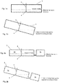
- Figure 1b schematically illustrates a fuel tank 3 of a field vehicle at a predetermined maximum angle of inclination for which reliable operation is to be guaranteed.
- the minimum volume of fuel that is required in order to ensure that it will still be possible to extract fuel at this angle of inclination may be calculated based on the geometry of the fuel tank. This volume of fuel is illustrated as X litres in Figure 1b .
- Figure 1a schematically illustrates the fuel tank 3 in its normal orientation, as experienced when the field vehicle is on flat, level ground, with the same volume of X litres of fuel within the fuel tank 3.
- the above-described calibration method is advantageous for preventing a field vehicle from becoming stranded by being operated on a significant incline with insufficient fuel.
- calibrating the fuel level monitoring system to intentionally under-report the actual volume of fuel remaining in the fuel tank reduces the usable volume of fuel that is visible to an operator of the vehicle, as indicated in Figures 1a and 1b , thereby reducing the range of the field vehicle and increasing the frequency at which the fuel tank will require refilling.
- the above-described problem of reduced effective fuel tank volume may be particularly pronounced in field vehicles having fuel tanks that are comparatively wide and shallow, as is often the case with forage harvesters. This is because in fuel tanks that are comparatively wide and shallow fuel can be displaced further from the outlet than in fuel tanks that are narrower and deeper, and so a higher zero level may be required in order to meet the same steepest slope requirement.
- This problem may also be heightened in field vehicles having fuel tanks 3 that comprise an auxiliary chamber 3b that is in fluid communication with the main chamber 3a in which the fuel sensor 5 is located, as schematically illustrated in Figures 2a and 2b .
- a fuel level monitoring system for a field vehicle, the fuel level monitoring system comprising: a fuel level sensor that is configured to generate a sensor signal indicative of a measured fuel level in a fuel tank of the field vehicle; a calibration mode selector that is configured to generate a calibration mode selection signal indicative of a selected calibration mode; and a control module comprising an input that is configured to receive the sensor signal and to receive the calibration mode selection signal, and an output that is configured to output a signal indicative of a calibrated fuel level; wherein the control module is configured to selectively switch between a plurality of calibration modes having different calibration settings in dependence on the calibration mode selection signal; and is configured to generate the output signal in dependence on the measured fuel level and further in dependence on the calibration setting of the selected calibration mode.
- the term "measured fuel level” may refer either to a directly measured surface level of the fuel within the fuel tank, or alternatively to a calculated volume of fuel within the fuel tank. Moreover, in either case, the measured fuel level may optionally be corrected in order to take account of the natural variation in fuel level readings that are obtained for the same fuel volume at different angles of inclination due to the movement of fuel within the fuel tank.
- the calibration setting is a setting that governs the relationship between the measured fuel level and the calibrated fuel level that is communicated to an operator of the field vehicle.
- the calibration settings of the respective calibration modes may be defined by any suitable number of set points or any suitable equations for mapping the measured fuel level onto the calibrated fuel level.
- control module being selectively switchable between a plurality of calibration modes having different calibration settings means that the calibration setting is adjustable during use of the field vehicle (that is while the field vehicle is in the possession of an operator) and not only during design, manufacture or initial calibration of the field vehicle.
- the present invention eliminates the need for the calibration setting to be fixed during design or manufacture of the field vehicle, and instead allows the fuel level to be indicated to an operator of the field vehicle using a calibration setting that is well suited to the environment in which the field vehicle is operating. For example if the field vehicle is operating in an area that is known to include significant inclines, then a calibration setting that under-represents the actual quantity of fuel that remains in the fuel tank can be used in order to reduce the probability of the fuel level falling below a critical level required for continued operation at a given angle of inclination.
- the calibration settings of the respective calibration modes may comprise different zero levels.
- the zero level of a calibration mode is the measured fuel level at which the fuel tank is indicated to be empty when the field vehicle is on flat level ground.
- a calibration mode with a comparatively low zero level may be engaged in order to increase the effective fuel tank volume that is visible to an operator of the field vehicle.
- a calibration mode with a comparatively high zero level may be engaged in order to reduce the probability of the fuel level falling below a critical level required for continued operation at a given angle of inclination.
- the calibration modes may include at least one flat mode and at least one non-flat mode.
- the flat mode may be intended primarily for use in flat areas (for example in flat fields and in geographical regions that are known to be predominantly flat), and the non-flat mode may be intended primarily for use in non-flat areas (for example in fields and geographical regions that are known to include significant inclines).
- the flat mode may have a zero level that is lower than the zero level of the non-flat mode.
- the zero level of the flat mode may correspond to an actual fuel volume that is at least 50% lower than the actual fuel volume represented by the zero level of the non-flat mode, although other values are also possible.
- the calibration modes may also include at least one intermediate mode intended for use in areas with intermediate terrain characteristics.
- the intermediate mode may have a zero level that is higher than the zero level of the flat mode but lower than the zero level of the non-flat mode.
- the flat, intermediate and non-flat calibration modes may equally be referred to by any other suitable names.
- the flat mode may be referred to as a low zero level mode and the non-flat mode may be referred to as a high zero level mode.
- it may be possible to select the "non-flat mode" while the field vehicle is operating in a generally flat area and vice-versa to thereby control the calibration settings of the fuel level monitoring system in a desired manner independently of the characteristics of the local terrain.
- the control module may store the calibration modes as discrete selectable calibration modes with pre-set calibration settings.
- the stored calibration modes may comprise a series of calibration modes with progressively different calibration settings, for example the flat mode, intermediate mode(s) and non-flat mode described above.
- control module may be configured to adjust at least one characteristic of the calibration setting in dependence on the calibration mode selection signal to thereby change the calibration mode.
- control module may be configured to adjust at least one set point of the calibration setting such as the zero level of the calibration setting along a scale between maximum and minimum permitted values in dependence on the calibration mode selection signal. In this case, it may not be necessary for the control module to store discrete calibration modes with pre-set calibration settings.
- the calibration mode selector may be configured to generate the calibration mode selection signal in dependence on a command entered by an operator or end user of the field vehicle, for example a driver.
- the calibration mode selector may be configured to generate a calibration mode selection signal identifying a pre-set calibration mode or identifying an adjustment to a characteristic of the calibration setting that has been requested by an operator of the vehicle.
- the command may be entered using any suitable input device of the field vehicle that is capable of receiving commands from an operator, for example a touch screen display or a control panel including one or more physical control elements.
- the calibration mode selector may be configured to generate the calibration mode selection signal in dependence on an identified geographical area.
- the calibration mode selector may be configured to identify the geographical area in which the field vehicle is located (or towards which the field vehicle is heading), and to generate a calibration mode selection signal identifying a pre-set calibration mode or identifying an adjustment to a characteristic of the calibration setting based on the terrain characteristics of the identified geographical area.
- area does not refer to a precise instantaneous location of the field vehicle, but rather to a broader area such as a field or a geographical region in which the field vehicle may be operated. Therefore the calibration mode is not changed continuously based on the instantaneous location of the field vehicle, but is instead set to match the general characteristics of the local terrain.
- the fuel level monitoring system may be configured to change the calibration mode automatically without requiring any input from an operator of the field vehicle, although in other embodiments the fuel level monitoring system may be configured to may be configured to request manual confirmation from the operator before changing the calibration mode.
- the control module may be configured to continue to operate in the selected calibration mode until a further calibration mode selection signal has been received, the further calibration mode selection signal being indicative of a different calibration mode.
- the control module may be configured to continue to operate in the selected calibration mode irrespective of the current or instantaneous angle of inclination of the field vehicle.
- the fuel level monitoring system may further comprise an interface system that is configured to provide an indication of the current fuel level of the fuel tank to an operator of the field vehicle in dependence on the output signal indicative of the calibrated fuel level.
- the interface system may comprise a display device such as a display screen or a gauge that is configured to display the current fuel level and/or a notification device such as a warning light or a speaker that is configured to provide a low fuel level warning.
- a field vehicle comprising a fuel level monitoring system as described above.
- field vehicles are vehicles that are designed and intended to perform agricultural work in field environments.
- the field vehicle may, for example, be a forage harvester, also known as a silage harvester, forager or chopper.
- the present invention may also be applied to other types of field vehicle, including, for example, combine harvesters.
- the present invention may be especially advantageous when applied to forager harvesters because forage harvesters often include fuel tanks that are comparatively wide and shallow and may therefore require a comparatively high zero level in order to ensure that sufficient fuel remains in the fuel tank to enable the field vehicle to be operated on a given incline.
- the fuel tank may have a depth that is significantly lower, for example, at least 50% lower, than a longitudinal or transverse extent of the fuel tank.
- the fuel tank of the field vehicle may comprise a first storage chamber in which the fuel sensor is located, and a second storage chamber that is in fluid communication with the first storage chamber. It will be appreciated that the present invention may also be applied to field vehicles in which the fuel tank only includes a single fuel tank that is not divided into separate first and second storage chambers. However, the present invention may be especially advantageous when applied to field vehicles in which the fuel tank comprises an auxiliary chamber in addition to the main chamber in which the fuel level is measured because fuel tanks of this type may require a comparatively high zero level in order to ensure that sufficient fuel remains in the fuel tank to enable the field vehicle to be operated on a given incline.
- the second storage chamber may optionally have a lower capacity than the first storage chamber, and may be provided at any suitable location relative to the first storage chamber.
- a method of monitoring a fuel level in a fuel tank of a field vehicle comprising: measuring the level of fuel in the fuel tank using a fuel level sensor; selecting a calibration mode from a plurality of possible calibration modes; and operating an interface system to provide an indication of the current fuel level of the fuel tank to an operator of the field vehicle in dependence on the measured fuel level and further in dependence on the calibration setting of the selected calibration mode.
- the calibration mode may be selected manually by an operator of the field vehicle.
- the calibration mode may be selected using any suitable input device of the field vehicle, for example a touch screen display or a control panel including one or more physical control elements.
- the calibration mode may be selected automatically in dependence on an identified geographical area.
- the automatically selected calibration mode may optionally be confirmed manually by an operator of the field vehicle.
- the step of providing an indication of the current fuel level of the fuel tank may comprise operating a display device such as a display screen or a gauge to display the current fuel level.
- the step of providing an indication of the current fuel level of the fuel tank may comprise operating a notification device such as a warning light or a speaker to provide a low fuel level warning.
- the method may further comprise any steps associated with normal operation of a fuel level monitoring system as described above in connection with the first aspect of the present invention.
- FIG 3 schematically illustrates a forage harvester 1 comprising a fuel level monitoring system 10 in accordance with one possible embodiment of the present invention.
- the forage harvester 1 comprises an internal combustion engine 2 for propelling the forage harvester 1 in use, and a fuel tank 3 for storing fuel to be supplied to the internal combustion engine 2.
- the fuel tank 3 is illustrated schematically in isolation in Figures 2a and 2b
- the fuel level monitoring system 10 is illustrated schematically in Figure 4 .
- the remaining features of the forage harvester 1, including the silage cutting and processing stages, are conventional and well known to the skilled person, and so are not described in more detail.
- the fuel tank 3 comprises a main storage chamber 3a and an auxiliary chamber 3b that is in fluid communication with the main storage chamber 3a.
- the main storage chamber 3a is comparatively wide and shallow in design, and may be provided at any suitable location within the forage harvester 1.
- the auxiliary chamber 3b is smaller than the main storage chamber 3a, and may be provided at any suitable location relative to the main storage chamber 3a, for example in front of, to the rear of or to the side of the main storage chamber 3a.
- the purpose of the auxiliary chamber 3b is to increase the total capacity of the fuel tank 3.
- the fuel tank 3 further comprises an outlet 4 through which fuel may be extracted for supply to the internal combustion engine 2.
- the outlet 4 is located adjacent to the lower wall of the main storage chamber 3a at an approximately central location.
- the fuel tank 3 is provided with a fuel level sensor 5.
- the fuel level sensor 5 is a vertical float type level sensor comprising a vertically extending shaft mounted at an approximately central location within the main storage chamber 3a, and a float that is slidingly mounted on the shaft and configured to selectively open and close a series of reed contacts to thereby change the resistance of the fuel level sensor 5 in dependence on the position of the float along the shaft.
- the fuel level sensor 5 is configured to generate a sensor signal 20 indicative of a measured fuel level in the fuel tank 3 based on the resistance of the fuel level sensor 5.
- the sensor signal 20 is based directly on the position of the float along the shaft, and so represents the level of the surface of the fuel at the location of the fuel level sensor 5.
- the outlet 4 of the fuel tank 3 is integrated with the shaft of the fuel level sensor 5 adjacent to a lower end of the shaft.
- fuel may be extracted from the fuel tank 3 through the shaft of the fuel level sensor 5.
- the outlet 4 of the fuel tank 3 may equally be provided separately to the fuel level sensor 5, for example through the lower wall of the fuel tank 3.
- the fuel level monitoring system 10 comprises a control module 11 having an input 11a that is configured to receive the sensor signal 20 indicative of the measured fuel level from the fuel level sensor 5.
- the control module 11 may optionally be configured to apply a correction to the measured fuel level as detected by the fuel level sensor 5 in dependence on the current angle of inclination of the forage harvester 1 in order to take account of the natural variation in fuel level readings that are obtained for the same fuel volume at different angles of inclination due to the movement of fuel within the fuel tank 3.
- the control module 11 is configured to calculate a calibrated fuel level in dependence on the measured fuel level (either as originally detected by the fuel level sensor or as corrected) and further in dependence on a calibration setting applied by the control module 11, as described in more detail below.
- the control module 11 further comprises an output 11b that is configured to output a signal 21 indicative of the calibrated fuel level to an interface system 12.
- the interface system 12 comprises a display device 13 such as a display screen or a fuel gauge that is located within the cabin of the forage harvester 1 and configured to display the calibrated fuel level to a driver of the forage harvester 1.
- the interface system 12 may also include a notification device 14 such as a warning light or a speaker that is configured to provide a low fuel level warning if the calibrated fuel level falls below a warning threshold.
- the control module 11 stores at least two different calibration modes each including different calibration settings that govern the relationship between the measured fuel level (as measured by the fuel level sensor 5) and the calibrated fuel level which is displayed to the driver of the forage harvester 1.
- the calibration settings of the respective calibration modes may be defined by any suitable number of set points or any suitable equations for mapping the measured fuel level onto the calibrated fuel level, and each define a zero level at which the fuel tank 3 is indicated to be empty when the forage harvester 1 is on flat level ground.
- the stored calibration modes include at least a flat mode that is intended primarily for use in areas that are predominantly flat, and a non-flat mode that is intended primarily for use in areas that include significant inclines.
- the calibration settings of the flat mode and the non-flat modes define different zero levels, with the zero level of the flat mode being significantly lower than the zero level of the non-flat mode.
- the stored calibration modes may optionally further comprise at least one intermediate mode having a zero level that is higher than the zero level of the flat mode but lower than the zero level of the non-flat mode.
- the fuel level monitoring system 10 further comprises an input system 15 located within the cabin of the forage harvester 1 for allowing the driver to select a desired calibration mode from the calibration modes stored by the control module 11.
- the input system 15 may, for example, comprise a touch screen display via which the driver may select the desired calibration mode from a menu, or alternatively one or more physical control elements such as buttons corresponding to the respective calibration modes. In either case, the input system 15 is configured to receive a command from the driver indicative of a desired calibration mode, and to generate a calibration mode selection signal 22 identifying the selected calibration mode.
- the control module 11 is configured to receive the calibration mode selection signal 22 generated by the input system 15, and to activate the selected calibration mode in dependence on the received calibration mode selection signal 22.
- the calibration settings of the selected calibration mode are then used in calculating the calibrated fuel level until a different calibration made has been selected using the input system 15. In this way, it is possible for the driver of the forage harvester 1 to selectively switch the fuel level monitoring system 10 between the plurality of stored calibration modes to suit the environment in which the forage harvester 1 is working.
- the flat mode may be selected, in which case the fuel level monitoring system 10 will not indicate that the fuel tank 3 is empty until the actual fuel level in the fuel tank 3 has fallen below the comparatively low zero level of the flat mode. In this case the effective fuel tank volume that is visible to the driver is maximised.
- the non-flat mode may be selected, in which case the fuel level monitoring system 10 will indicate that the fuel tank 3 is empty when the actual fuel level reaches the comparatively higher zero level of the non-flat mode. In this case the driver of the forage harvester 1 will be prompted to refill the fuel tank 3 while a comparatively larger volume of fuel remains in the fuel tank 3, thereby making it less likely that the fuel volume will fall below the minimum volume required in order to permit continued operation of the forage harvester 1 on an incline.
- the zero level of the non-flat mode may be set to correspond to the fuel level measurement obtained by the fuel level sensor 5 when the forage harvester 1 is on flat level ground and the volume of fuel within the fuel tank 3 is equal to the volume of fuel that is required for reliable operation at a predetermined maximum angle of inclination. In this case, it can be ensured that there will still be sufficient fuel in the fuel tank 3 to enable the forage harvester 1 to operate up to the predetermined maximum angle of inclination as long as the non-flat mode is engaged and the fuel level monitoring system has not yet indicated that the fuel tank 3 is empty.
- the fuel level monitoring system 10 may further comprise an additional mode selector that is configured to change the calibration mode automatically in dependence on the geographical area in which the forage harvester is operating.
- the fuel level monitoring system 10 may additionally comprise a location module 16, for example a GPS location module, that is configured to detect the location of the forage harvester 1, and to identify the geographical area (for example the field or region) in which the forage harvester 1 is operating.
- the location module 16 may further be configured to generate a calibration mode selection signal 22 identifying a calibration mode that is suitable for use in the identified geographical area based on the local terrain characteristics.
- the calibration mode may, for example, be selected using a pre-configured database including terrain information, or alternatively based on historic data generated by the forage harvester during previous periods of operation in the identified geographical area. In this way, the calibration mode may be adjusted automatically to suit the terrain characteristics of the local area.
- the control module 11 may optionally be configured to request manual confirmation from the driver before permitting a change in the selected calibration mode.
- the present invention may also be applied to other types of field vehicle besides forage harvesters, including field vehicles having different fuel tank configurations and different fuel level sensors to those described above.
- the fuel level monitoring system 10 is configured to selectively switch between discrete selectable calibration modes with pre-set calibration settings.
- the fuel level monitoring system 10 may alternatively, or additionally, be configured to adjust at least one characteristic of the calibration setting to thereby change the calibration mode.
- the fuel level monitoring system 10 may be configured to permit the driver to manually adjust the zero level along a scale between maximum and minimum permitted values using the input system, or alternatively may be configured to adjust the zero level along a scale automatically in dependence on the geographical area in which the forage harvester is operating, to thereby change the calibration mode.
- control modules and systems including the main control module 11, the interface system 12, the input system 15, and the location module 16.
- these control modules and systems are described and illustrated as being discrete and self-contained units that are in communication with each other.
- control modules and systems may be formed by any suitable arrangement of processors and memory modules provided at any suitable location or locations within the field vehicle, and may be integrated with each other in any suitable manner as part of the overall control system of the field vehicle.
- the above description refers to various different signals being outputted by particular control modules and systems.
- the above-described signals may be generated and processed internally within the overall control system of the forage harvester in any suitable manner.
Abstract
Description
- The present disclosure relates to a fuel level monitoring system and particularly, but not exclusively, to a fuel level monitoring system for a field vehicle such as a forage harvester.
- When a field vehicle such as a forage harvester (also known as a silage harvester, forager or chopper) is operated on flat, level ground, the fuel within the
fuel tank 3 of the field vehicle will generally cover anoutlet 4 located near the base of the fuel tank thereby enabling fuel to be extracted as long as there is still fuel within the fuel tank, as schematically illustrated inFigure 1a . However, field vehicles may also from time to time be required to operate on a significant incline. When a field vehicle is operated on an incline, the fuel in thefuel tank 3 will naturally move towards the lower side of the fuel tank, as schematically illustrated inFigure 1b . If the field vehicle is operated on a sufficiently steep incline then the fuel in thefuel tank 3 may no longer cover theoutlet 4 even if a significant volume of fuel still remains within thefuel tank 3. In this case, it may no longer be possible to extract fuel from thefuel tank 3, and so the field vehicle may be at risk of becoming stranded. - In order to reduce the probability of field vehicles becoming stranded, the fuel level monitoring systems of field vehicles are typically calibrated to under-report the actual volume of fuel remaining in the
fuel tank 3. In particular, the fuel level monitoring systems of field vehicles may be calibrated with a zero level (that is the measured fuel level at which thefuel tank 3 is indicated to be empty when the field vehicle is on flat level ground) that is sufficiently high to ensure that there will still be sufficient fuel in thefuel tank 3 to enable the field vehicle to operate up to a predetermined maximum angle of inclination for which reliable operation is to be guaranteed as long as the fuel level monitoring system has not yet indicated that thefuel tank 3 is empty. - For example,
Figure 1b schematically illustrates afuel tank 3 of a field vehicle at a predetermined maximum angle of inclination for which reliable operation is to be guaranteed. The minimum volume of fuel that is required in order to ensure that it will still be possible to extract fuel at this angle of inclination may be calculated based on the geometry of the fuel tank. This volume of fuel is illustrated as X litres inFigure 1b . -
Figure 1a schematically illustrates thefuel tank 3 in its normal orientation, as experienced when the field vehicle is on flat, level ground, with the same volume of X litres of fuel within thefuel tank 3. If the fuel level monitoring system is calibrated to have a zero level that is equal to the fuel level measurement obtained by thefuel level sensor 5 when thefuel tank 3 is in its normal orientation and contains the minimum volume of fuel required for reliable operation at the predetermined maximum angle of inclination, as illustrated inFigure 1a , then the fuel level monitoring system will report that thefuel tank 3 is empty before the fuel volume falls below the minimum volume required for reliable operation up to the predetermined maximum angle of inclination. In this way the artificially high zero level will generally prevent the field vehicle from becoming stranded due to a lack of fuel flow (unless the field vehicle is operated beyond the predetermined maximum angle of inclination or after thefuel tank 3 has been reported to be empty). - The above-described calibration method is advantageous for preventing a field vehicle from becoming stranded by being operated on a significant incline with insufficient fuel. However, calibrating the fuel level monitoring system to intentionally under-report the actual volume of fuel remaining in the fuel tank reduces the usable volume of fuel that is visible to an operator of the vehicle, as indicated in
Figures 1a and 1b , thereby reducing the range of the field vehicle and increasing the frequency at which the fuel tank will require refilling. - The above-described problem of reduced effective fuel tank volume may be particularly pronounced in field vehicles having fuel tanks that are comparatively wide and shallow, as is often the case with forage harvesters. This is because in fuel tanks that are comparatively wide and shallow fuel can be displaced further from the outlet than in fuel tanks that are narrower and deeper, and so a higher zero level may be required in order to meet the same steepest slope requirement. This problem may also be heightened in field vehicles having
fuel tanks 3 that comprise anauxiliary chamber 3b that is in fluid communication with themain chamber 3a in which thefuel sensor 5 is located, as schematically illustrated inFigures 2a and 2b . This is because infuel tanks 3 of this type fuel can collect in theauxiliary chamber 3b when the field vehicle is operated on an incline, and so a higher zero level (illustrated as Y litres inFigure 2b ) may be required in order to meet a particular steepest slope requirement than would be necessary if the fuel tank only included a single chamber. - It is an aim of the present invention to address disadvantages associated with the prior art.
- According to an aspect of the present invention there is provided a fuel level monitoring system for a field vehicle, the fuel level monitoring system comprising: a fuel level sensor that is configured to generate a sensor signal indicative of a measured fuel level in a fuel tank of the field vehicle; a calibration mode selector that is configured to generate a calibration mode selection signal indicative of a selected calibration mode; and a control module comprising an input that is configured to receive the sensor signal and to receive the calibration mode selection signal, and an output that is configured to output a signal indicative of a calibrated fuel level; wherein the control module is configured to selectively switch between a plurality of calibration modes having different calibration settings in dependence on the calibration mode selection signal; and is configured to generate the output signal in dependence on the measured fuel level and further in dependence on the calibration setting of the selected calibration mode.
- It will be appreciated that the term "measured fuel level" may refer either to a directly measured surface level of the fuel within the fuel tank, or alternatively to a calculated volume of fuel within the fuel tank. Moreover, in either case, the measured fuel level may optionally be corrected in order to take account of the natural variation in fuel level readings that are obtained for the same fuel volume at different angles of inclination due to the movement of fuel within the fuel tank.
- It will further be appreciated that the calibration setting is a setting that governs the relationship between the measured fuel level and the calibrated fuel level that is communicated to an operator of the field vehicle. The calibration settings of the respective calibration modes may be defined by any suitable number of set points or any suitable equations for mapping the measured fuel level onto the calibrated fuel level.
- It will further be appreciated that the control module being selectively switchable between a plurality of calibration modes having different calibration settings means that the calibration setting is adjustable during use of the field vehicle (that is while the field vehicle is in the possession of an operator) and not only during design, manufacture or initial calibration of the field vehicle.
- By allowing the calibration setting to be adjusted, the present invention eliminates the need for the calibration setting to be fixed during design or manufacture of the field vehicle, and instead allows the fuel level to be indicated to an operator of the field vehicle using a calibration setting that is well suited to the environment in which the field vehicle is operating. For example if the field vehicle is operating in an area that is known to include significant inclines, then a calibration setting that under-represents the actual quantity of fuel that remains in the fuel tank can be used in order to reduce the probability of the fuel level falling below a critical level required for continued operation at a given angle of inclination. However, if the field vehicle is operating in an area that is known to be predominantly flat than a different calibration setting that provides a more accurate representation of the actual quantity of fuel that remains in the fuel tank can be used in order to increase the effective fuel tank volume that is visible to an operator of the field vehicle.
- The calibration settings of the respective calibration modes may comprise different zero levels. It will be appreciated that the zero level of a calibration mode is the measured fuel level at which the fuel tank is indicated to be empty when the field vehicle is on flat level ground. By enabling the fuel level monitoring system to switch between different calibration modes having different zero levels it is possible to change the amount of fuel that is guaranteed to remain in the fuel tank when the fuel level monitoring system indicates that the fuel level is low. For example, a calibration mode with a comparatively low zero level may be engaged in order to increase the effective fuel tank volume that is visible to an operator of the field vehicle. Alternatively, a calibration mode with a comparatively high zero level may be engaged in order to reduce the probability of the fuel level falling below a critical level required for continued operation at a given angle of inclination.
- The calibration modes may include at least one flat mode and at least one non-flat mode. The flat mode may be intended primarily for use in flat areas (for example in flat fields and in geographical regions that are known to be predominantly flat), and the non-flat mode may be intended primarily for use in non-flat areas (for example in fields and geographical regions that are known to include significant inclines). The flat mode may have a zero level that is lower than the zero level of the non-flat mode. For example, the zero level of the flat mode may correspond to an actual fuel volume that is at least 50% lower than the actual fuel volume represented by the zero level of the non-flat mode, although other values are also possible.
- The calibration modes may also include at least one intermediate mode intended for use in areas with intermediate terrain characteristics. The intermediate mode may have a zero level that is higher than the zero level of the flat mode but lower than the zero level of the non-flat mode.
- It will be appreciated that the flat, intermediate and non-flat calibration modes may equally be referred to by any other suitable names. For example, the flat mode may be referred to as a low zero level mode and the non-flat mode may be referred to as a high zero level mode. Moreover, it will be appreciated that it may be possible to select the "non-flat mode" while the field vehicle is operating in a generally flat area and vice-versa to thereby control the calibration settings of the fuel level monitoring system in a desired manner independently of the characteristics of the local terrain.
- The control module may store the calibration modes as discrete selectable calibration modes with pre-set calibration settings. The stored calibration modes may comprise a series of calibration modes with progressively different calibration settings, for example the flat mode, intermediate mode(s) and non-flat mode described above.
- Alternatively, or in addition, the control module may be configured to adjust at least one characteristic of the calibration setting in dependence on the calibration mode selection signal to thereby change the calibration mode. For example, the control module may be configured to adjust at least one set point of the calibration setting such as the zero level of the calibration setting along a scale between maximum and minimum permitted values in dependence on the calibration mode selection signal. In this case, it may not be necessary for the control module to store discrete calibration modes with pre-set calibration settings.
- The calibration mode selector may be configured to generate the calibration mode selection signal in dependence on a command entered by an operator or end user of the field vehicle, for example a driver. For example, the calibration mode selector may be configured to generate a calibration mode selection signal identifying a pre-set calibration mode or identifying an adjustment to a characteristic of the calibration setting that has been requested by an operator of the vehicle. The command may be entered using any suitable input device of the field vehicle that is capable of receiving commands from an operator, for example a touch screen display or a control panel including one or more physical control elements.
- Alternatively, or in addition, the calibration mode selector may be configured to generate the calibration mode selection signal in dependence on an identified geographical area. For example, the calibration mode selector may be configured to identify the geographical area in which the field vehicle is located (or towards which the field vehicle is heading), and to generate a calibration mode selection signal identifying a pre-set calibration mode or identifying an adjustment to a characteristic of the calibration setting based on the terrain characteristics of the identified geographical area. It will be appreciated that the term "area" does not refer to a precise instantaneous location of the field vehicle, but rather to a broader area such as a field or a geographical region in which the field vehicle may be operated. Therefore the calibration mode is not changed continuously based on the instantaneous location of the field vehicle, but is instead set to match the general characteristics of the local terrain.
- In some embodiments, the fuel level monitoring system may be configured to change the calibration mode automatically without requiring any input from an operator of the field vehicle, although in other embodiments the fuel level monitoring system may be configured to may be configured to request manual confirmation from the operator before changing the calibration mode.
- The control module may be configured to continue to operate in the selected calibration mode until a further calibration mode selection signal has been received, the further calibration mode selection signal being indicative of a different calibration mode. The control module may be configured to continue to operate in the selected calibration mode irrespective of the current or instantaneous angle of inclination of the field vehicle.
- The fuel level monitoring system may further comprise an interface system that is configured to provide an indication of the current fuel level of the fuel tank to an operator of the field vehicle in dependence on the output signal indicative of the calibrated fuel level. The interface system may comprise a display device such as a display screen or a gauge that is configured to display the current fuel level and/or a notification device such as a warning light or a speaker that is configured to provide a low fuel level warning.
- According to a further aspect of the present invention there is provided a field vehicle comprising a fuel level monitoring system as described above. It will be appreciated field vehicles are vehicles that are designed and intended to perform agricultural work in field environments. The field vehicle may, for example, be a forage harvester, also known as a silage harvester, forager or chopper. It will be appreciated that the present invention may also be applied to other types of field vehicle, including, for example, combine harvesters. However, the present invention may be especially advantageous when applied to forager harvesters because forage harvesters often include fuel tanks that are comparatively wide and shallow and may therefore require a comparatively high zero level in order to ensure that sufficient fuel remains in the fuel tank to enable the field vehicle to be operated on a given incline. The fuel tank may have a depth that is significantly lower, for example, at least 50% lower, than a longitudinal or transverse extent of the fuel tank.
- The fuel tank of the field vehicle may comprise a first storage chamber in which the fuel sensor is located, and a second storage chamber that is in fluid communication with the first storage chamber. It will be appreciated that the present invention may also be applied to field vehicles in which the fuel tank only includes a single fuel tank that is not divided into separate first and second storage chambers. However, the present invention may be especially advantageous when applied to field vehicles in which the fuel tank comprises an auxiliary chamber in addition to the main chamber in which the fuel level is measured because fuel tanks of this type may require a comparatively high zero level in order to ensure that sufficient fuel remains in the fuel tank to enable the field vehicle to be operated on a given incline. The second storage chamber may optionally have a lower capacity than the first storage chamber, and may be provided at any suitable location relative to the first storage chamber.
- According to a further aspect of the present invention there is provided a method of monitoring a fuel level in a fuel tank of a field vehicle, the method comprising: measuring the level of fuel in the fuel tank using a fuel level sensor; selecting a calibration mode from a plurality of possible calibration modes; and operating an interface system to provide an indication of the current fuel level of the fuel tank to an operator of the field vehicle in dependence on the measured fuel level and further in dependence on the calibration setting of the selected calibration mode.
- The calibration mode may be selected manually by an operator of the field vehicle. In this case the calibration mode may be selected using any suitable input device of the field vehicle, for example a touch screen display or a control panel including one or more physical control elements.
- Alternatively, the calibration mode may be selected automatically in dependence on an identified geographical area. In this case, the automatically selected calibration mode may optionally be confirmed manually by an operator of the field vehicle.
- The step of providing an indication of the current fuel level of the fuel tank may comprise operating a display device such as a display screen or a gauge to display the current fuel level. Alternatively, or in addition, the step of providing an indication of the current fuel level of the fuel tank may comprise operating a notification device such as a warning light or a speaker to provide a low fuel level warning.
- The method may further comprise any steps associated with normal operation of a fuel level monitoring system as described above in connection with the first aspect of the present invention.
- Within the scope of this application it is expressly intended that the various aspects, embodiments, examples and alternatives set out in the preceding paragraphs, in the claims and/or in the following description and drawings, and in particular the individual features thereof, may be taken independently or in any combination. That is, all embodiments and/or features of any embodiment can be combined in any way and/or combination, unless such features are incompatible. The applicant reserves the right to change any originally filed claim or file any new claim accordingly, including the right to amend any originally filed claim to depend from and/or incorporate any feature of any other claim although not originally claimed in that manner.
- One or more embodiments of the invention will now be described, by way of example only, with reference to the accompanying drawings, in which:
-
Figures 1a and 1b schematically illustrate a fuel tank of a field vehicle a) when the field vehicle is on flat, level ground and b) when the field vehicle is on an incline; -
Figures 2a and 2b schematically illustrate an alternative fuel tank arrangement of a field vehicle a) when the field vehicle is on flat, level ground and b) when the field vehicle is on an incline; -
Figure 3 schematically illustrates a forage harvester comprising a fuel level monitoring system according to one possible embodiment of the present invention; and -
Figure 4 schematically illustrates the fuel level monitoring system of the forage harvester illustrated inFigure 3 . -
Figure 3 schematically illustrates a forage harvester 1 comprising a fuellevel monitoring system 10 in accordance with one possible embodiment of the present invention. The forage harvester 1 comprises aninternal combustion engine 2 for propelling the forage harvester 1 in use, and afuel tank 3 for storing fuel to be supplied to theinternal combustion engine 2. Thefuel tank 3 is illustrated schematically in isolation inFigures 2a and 2b , and the fuellevel monitoring system 10 is illustrated schematically inFigure 4 . The remaining features of the forage harvester 1, including the silage cutting and processing stages, are conventional and well known to the skilled person, and so are not described in more detail. - As shown in
Figures 2a and 2b , thefuel tank 3 comprises amain storage chamber 3a and anauxiliary chamber 3b that is in fluid communication with themain storage chamber 3a. Themain storage chamber 3a is comparatively wide and shallow in design, and may be provided at any suitable location within the forage harvester 1. Theauxiliary chamber 3b is smaller than themain storage chamber 3a, and may be provided at any suitable location relative to themain storage chamber 3a, for example in front of, to the rear of or to the side of themain storage chamber 3a. The purpose of theauxiliary chamber 3b is to increase the total capacity of thefuel tank 3. - The
fuel tank 3 further comprises anoutlet 4 through which fuel may be extracted for supply to theinternal combustion engine 2. Theoutlet 4 is located adjacent to the lower wall of themain storage chamber 3a at an approximately central location. - The
fuel tank 3 is provided with afuel level sensor 5. In the present embodiment thefuel level sensor 5 is a vertical float type level sensor comprising a vertically extending shaft mounted at an approximately central location within themain storage chamber 3a, and a float that is slidingly mounted on the shaft and configured to selectively open and close a series of reed contacts to thereby change the resistance of thefuel level sensor 5 in dependence on the position of the float along the shaft. Thefuel level sensor 5 is configured to generate asensor signal 20 indicative of a measured fuel level in thefuel tank 3 based on the resistance of thefuel level sensor 5. In the present embodiment, thesensor signal 20 is based directly on the position of the float along the shaft, and so represents the level of the surface of the fuel at the location of thefuel level sensor 5. - In the embodiment illustrated in
Figures 2a and 2b theoutlet 4 of thefuel tank 3 is integrated with the shaft of thefuel level sensor 5 adjacent to a lower end of the shaft. In this case, fuel may be extracted from thefuel tank 3 through the shaft of thefuel level sensor 5. However, it will be appreciated that in other embodiments theoutlet 4 of thefuel tank 3 may equally be provided separately to thefuel level sensor 5, for example through the lower wall of thefuel tank 3. - As shown in
Figure 4 , the fuellevel monitoring system 10 comprises acontrol module 11 having aninput 11a that is configured to receive thesensor signal 20 indicative of the measured fuel level from thefuel level sensor 5. Thecontrol module 11 may optionally be configured to apply a correction to the measured fuel level as detected by thefuel level sensor 5 in dependence on the current angle of inclination of the forage harvester 1 in order to take account of the natural variation in fuel level readings that are obtained for the same fuel volume at different angles of inclination due to the movement of fuel within thefuel tank 3. In either case, thecontrol module 11 is configured to calculate a calibrated fuel level in dependence on the measured fuel level (either as originally detected by the fuel level sensor or as corrected) and further in dependence on a calibration setting applied by thecontrol module 11, as described in more detail below. - The
control module 11 further comprises anoutput 11b that is configured to output asignal 21 indicative of the calibrated fuel level to aninterface system 12. Theinterface system 12 comprises adisplay device 13 such as a display screen or a fuel gauge that is located within the cabin of the forage harvester 1 and configured to display the calibrated fuel level to a driver of the forage harvester 1. Theinterface system 12 may also include anotification device 14 such as a warning light or a speaker that is configured to provide a low fuel level warning if the calibrated fuel level falls below a warning threshold. - In accordance with an embodiment of the present invention, the
control module 11 stores at least two different calibration modes each including different calibration settings that govern the relationship between the measured fuel level (as measured by the fuel level sensor 5) and the calibrated fuel level which is displayed to the driver of the forage harvester 1. The calibration settings of the respective calibration modes may be defined by any suitable number of set points or any suitable equations for mapping the measured fuel level onto the calibrated fuel level, and each define a zero level at which thefuel tank 3 is indicated to be empty when the forage harvester 1 is on flat level ground. - The stored calibration modes include at least a flat mode that is intended primarily for use in areas that are predominantly flat, and a non-flat mode that is intended primarily for use in areas that include significant inclines. The calibration settings of the flat mode and the non-flat modes define different zero levels, with the zero level of the flat mode being significantly lower than the zero level of the non-flat mode. The stored calibration modes may optionally further comprise at least one intermediate mode having a zero level that is higher than the zero level of the flat mode but lower than the zero level of the non-flat mode.
- The fuel
level monitoring system 10 further comprises aninput system 15 located within the cabin of the forage harvester 1 for allowing the driver to select a desired calibration mode from the calibration modes stored by thecontrol module 11. Theinput system 15 may, for example, comprise a touch screen display via which the driver may select the desired calibration mode from a menu, or alternatively one or more physical control elements such as buttons corresponding to the respective calibration modes. In either case, theinput system 15 is configured to receive a command from the driver indicative of a desired calibration mode, and to generate a calibrationmode selection signal 22 identifying the selected calibration mode. - The
control module 11 is configured to receive the calibrationmode selection signal 22 generated by theinput system 15, and to activate the selected calibration mode in dependence on the received calibrationmode selection signal 22. The calibration settings of the selected calibration mode are then used in calculating the calibrated fuel level until a different calibration made has been selected using theinput system 15. In this way, it is possible for the driver of the forage harvester 1 to selectively switch the fuellevel monitoring system 10 between the plurality of stored calibration modes to suit the environment in which the forage harvester 1 is working. - For example, if the forage harvester 1 is operating in an environment that is known to be predominantly flat then the flat mode may be selected, in which case the fuel
level monitoring system 10 will not indicate that thefuel tank 3 is empty until the actual fuel level in thefuel tank 3 has fallen below the comparatively low zero level of the flat mode. In this case the effective fuel tank volume that is visible to the driver is maximised. - In contrast, if the forage harvester 1 is operating in an environment that is known to include significant inclines then the non-flat mode may be selected, in which case the fuel
level monitoring system 10 will indicate that thefuel tank 3 is empty when the actual fuel level reaches the comparatively higher zero level of the non-flat mode. In this case the driver of the forage harvester 1 will be prompted to refill thefuel tank 3 while a comparatively larger volume of fuel remains in thefuel tank 3, thereby making it less likely that the fuel volume will fall below the minimum volume required in order to permit continued operation of the forage harvester 1 on an incline. - In one particular example the zero level of the non-flat mode may be set to correspond to the fuel level measurement obtained by the
fuel level sensor 5 when the forage harvester 1 is on flat level ground and the volume of fuel within thefuel tank 3 is equal to the volume of fuel that is required for reliable operation at a predetermined maximum angle of inclination. In this case, it can be ensured that there will still be sufficient fuel in thefuel tank 3 to enable the forage harvester 1 to operate up to the predetermined maximum angle of inclination as long as the non-flat mode is engaged and the fuel level monitoring system has not yet indicated that thefuel tank 3 is empty. - In some embodiments, the fuel
level monitoring system 10 may further comprise an additional mode selector that is configured to change the calibration mode automatically in dependence on the geographical area in which the forage harvester is operating. For example, as also illustrated inFigure 4 , the fuellevel monitoring system 10 may additionally comprise alocation module 16, for example a GPS location module, that is configured to detect the location of the forage harvester 1, and to identify the geographical area (for example the field or region) in which the forage harvester 1 is operating. Thelocation module 16 may further be configured to generate a calibrationmode selection signal 22 identifying a calibration mode that is suitable for use in the identified geographical area based on the local terrain characteristics. The calibration mode may, for example, be selected using a pre-configured database including terrain information, or alternatively based on historic data generated by the forage harvester during previous periods of operation in the identified geographical area. In this way, the calibration mode may be adjusted automatically to suit the terrain characteristics of the local area. However, thecontrol module 11 may optionally be configured to request manual confirmation from the driver before permitting a change in the selected calibration mode. - The above description relates to one possible embodiment of the present invention. However, many modifications may be made to the above example without departing from the scope of the present invention as defined in the accompanying claims.
- For example, the present invention may also be applied to other types of field vehicle besides forage harvesters, including field vehicles having different fuel tank configurations and different fuel level sensors to those described above.
- In addition, in the above-described embodiment, the fuel
level monitoring system 10 is configured to selectively switch between discrete selectable calibration modes with pre-set calibration settings. However, in other examples the fuellevel monitoring system 10 may alternatively, or additionally, be configured to adjust at least one characteristic of the calibration setting to thereby change the calibration mode. For example, the fuellevel monitoring system 10 may be configured to permit the driver to manually adjust the zero level along a scale between maximum and minimum permitted values using the input system, or alternatively may be configured to adjust the zero level along a scale automatically in dependence on the geographical area in which the forage harvester is operating, to thereby change the calibration mode. - The above description refers to various control modules and systems, including the
main control module 11, theinterface system 12, theinput system 15, and thelocation module 16. For ease of reference these control modules and systems are described and illustrated as being discrete and self-contained units that are in communication with each other. However, it will be appreciated that the above-described control modules and systems may be formed by any suitable arrangement of processors and memory modules provided at any suitable location or locations within the field vehicle, and may be integrated with each other in any suitable manner as part of the overall control system of the field vehicle. In addition, the above description refers to various different signals being outputted by particular control modules and systems. However, it will be appreciated that the above-described signals may be generated and processed internally within the overall control system of the forage harvester in any suitable manner.
Claims (15)
- A fuel level monitoring system (10) for a field vehicle (1), the fuel level monitoring system comprising:a fuel level sensor (5) that is configured to generate a sensor signal (20) indicative of a measured fuel level in a fuel tank (3) of the field vehicle (1);a calibration mode selector (15, 16) that is configured to generate a calibration mode selection signal (22) indicative of a selected calibration mode; anda control module (11) comprising an input (11a) that is configured to receive the sensor signal (20) and to receive the calibration mode selection signal (22), and an output (11b) that is configured to output a signal (21) indicative of a calibrated fuel level;wherein the control module (11) is configured to selectively switch between a plurality of calibration modes having different calibration settings in dependence on the calibration mode selection signal (22); and is configured to generate the output signal (21) in dependence on the measured fuel level and further in dependence on the calibration setting of the selected calibration mode.
- A fuel level monitoring system (10) according to Claim 1, wherein calibration settings of the respective calibration modes comprise different zero levels.
- A fuel level monitoring system (10) according to Claim 1 or Claim 2, wherein the calibration modes include at least one flat mode intended primarily for use in flat areas and at least one non-flat mode intended primarily for use in non-flat areas.
- A fuel level monitoring system (10) according to any preceding claim, wherein the control module (11) stores the calibration modes as discrete selectable calibration modes with pre-set calibration settings.
- A fuel level monitoring system (10) according to any preceding claim, wherein the control module (11) is configured to adjust at least one characteristic of the calibration setting in dependence on the calibration mode selection signal (22) to thereby change the calibration mode.
- A fuel level monitoring system (10) according to any preceding claim, wherein the calibration mode selector (15) is configured to generate the calibration mode selection signal (22) in dependence on a command entered by an operator of the field vehicle (1).
- A fuel level monitoring system (10) according to any preceding claim, wherein the calibration mode selector (16) is configured to generate the calibration mode selection signal (22) in dependence on an identified geographical area.
- A fuel level monitoring system (10) according to any preceding claim, further comprising an interface system (12) that is configured to provide an indication of the current fuel level of the fuel tank (3) to an operator of the field vehicle in dependence on the output signal (21) indicative of the calibrated fuel level.
- A field vehicle (1) comprising a fuel level monitoring system (10) according to any preceding claim, optionally wherein the field vehicle (1) is a forage harvester.
- A field vehicle (1) according to claim 9, wherein the fuel tank (3) of the field vehicle (1) comprises a first storage chamber (3a) in which the fuel sensor (5) is located, and a second storage chamber (3b) that is in fluid communication with the first storage chamber (3a).
- A method of monitoring a fuel level in a fuel tank (3) of a field vehicle (1), the method comprising:measuring the level of fuel in the fuel tank (3) using a fuel level sensor (5);selecting a calibration mode from a plurality of possible calibration modes; andoperating an interface system (12) to provide an indication of the current fuel level of the fuel tank (3) to an operator of the field vehicle (1) in dependence on the measured fuel level and further in dependence on the calibration setting of the selected calibration mode.
- A method according to Claim 11, wherein the calibration mode is selected manually by an operator of the field vehicle (1).
- A method according to Claim 11, wherein the calibration mode is selected automatically in dependence on an identified geographical area.
- A method according to any of Claims 11 to 13, wherein the step of providing an indication of the current fuel level of the fuel tank (3) comprises operating a display device (13) to display the current fuel level.
- A non-transitory computer readable storage medium comprising computer readable instructions for a computer processor to carry out the method of any of Claims 11 to 14.
Priority Applications (1)
| Application Number | Priority Date | Filing Date | Title |
|---|---|---|---|
| EP19173814.5A EP3736548B1 (en) | 2019-05-10 | 2019-05-10 | Fuel level monitoring system for a field vehicle |
Applications Claiming Priority (1)
| Application Number | Priority Date | Filing Date | Title |
|---|---|---|---|
| EP19173814.5A EP3736548B1 (en) | 2019-05-10 | 2019-05-10 | Fuel level monitoring system for a field vehicle |
Publications (2)
| Publication Number | Publication Date |
|---|---|
| EP3736548A1 true EP3736548A1 (en) | 2020-11-11 |
| EP3736548B1 EP3736548B1 (en) | 2022-08-24 |
Family
ID=66483925
Family Applications (1)
| Application Number | Title | Priority Date | Filing Date |
|---|---|---|---|
| EP19173814.5A Active EP3736548B1 (en) | 2019-05-10 | 2019-05-10 | Fuel level monitoring system for a field vehicle |
Country Status (1)
| Country | Link |
|---|---|
| EP (1) | EP3736548B1 (en) |
Citations (4)
| Publication number | Priority date | Publication date | Assignee | Title |
|---|---|---|---|---|
| DE69324648T2 (en) * | 1992-10-26 | 1999-11-11 | Solvay | Manufacturing method for a liquid tank provided with a sensor; Application in the manufacture of a plastic tank and tank manufactured in this way |
| US8175856B2 (en) * | 2008-06-24 | 2012-05-08 | Inergy Automotive Systems Research (S.A.) | Method for simulating the gauging of a liquid tank |
| DE102017203312A1 (en) * | 2016-03-04 | 2017-09-07 | Coavis | DEVICE FOR DETECTING A FUEL LEVEL USING AN ELECTRIC CAPACITY |
| US20180335297A1 (en) * | 2017-05-17 | 2018-11-22 | A.C. Dispensing Equipment Inc. | Optical fluid level measurement system for dispensing apparatus |
-
2019
- 2019-05-10 EP EP19173814.5A patent/EP3736548B1/en active Active
Patent Citations (4)
| Publication number | Priority date | Publication date | Assignee | Title |
|---|---|---|---|---|
| DE69324648T2 (en) * | 1992-10-26 | 1999-11-11 | Solvay | Manufacturing method for a liquid tank provided with a sensor; Application in the manufacture of a plastic tank and tank manufactured in this way |
| US8175856B2 (en) * | 2008-06-24 | 2012-05-08 | Inergy Automotive Systems Research (S.A.) | Method for simulating the gauging of a liquid tank |
| DE102017203312A1 (en) * | 2016-03-04 | 2017-09-07 | Coavis | DEVICE FOR DETECTING A FUEL LEVEL USING AN ELECTRIC CAPACITY |
| US20180335297A1 (en) * | 2017-05-17 | 2018-11-22 | A.C. Dispensing Equipment Inc. | Optical fluid level measurement system for dispensing apparatus |
Non-Patent Citations (1)
| Title |
|---|
| KOCH P: "SIMPLE PROGRAM CALCULATES PARTIAL LIQUID VOLUMES IN VESSELS", OIL AND GAS JOURNAL, PENNWELL, HOUSTON, TX, US, vol. 90, no. 15, 13 April 1992 (1992-04-13), pages 54 - 57, XP000263676, ISSN: 0030-1388 * |
Also Published As
| Publication number | Publication date |
|---|---|
| EP3736548B1 (en) | 2022-08-24 |
Similar Documents
| Publication | Publication Date | Title |
|---|---|---|
| EP3125670B1 (en) | Agricultural implement operator monitoring methods | |
| EP2250871B1 (en) | Scalable grain tank fill level display | |
| US6282953B1 (en) | Solid state fuel level sensing | |
| EP2538764B1 (en) | System and method for controlling harvest operations | |
| US6002328A (en) | Tank display system and method for determining the remaining volume in a tank | |
| US9371071B2 (en) | Method for refueling motor vehicles | |
| US5105663A (en) | Apparatus and method for measuring low fuel level in a fuel tank | |
| US6263916B1 (en) | Tank system | |
| US6650974B2 (en) | Methods and apparatus for automated flight preparation | |
| US6252499B1 (en) | Fuel supply indicator arrangement for a motor vehicle fuel tank | |
| US7059167B2 (en) | Method and arrangement for indirectly determining fill characteristics of a fluid tank on a marine vessel | |
| EP3736548B1 (en) | Fuel level monitoring system for a field vehicle | |
| JP6425859B1 (en) | Fuel consumption measuring system for working vehicle and fuel consumption measuring method for working vehicle | |
| US5485740A (en) | Method of calibration for gauging fuel in an automotive tank | |
| EP2466278B1 (en) | Method for estimating the fuel level in a vehicle tank and corresponding fuel level estimation system | |
| EP3392626A1 (en) | Aircraft fuel gauging method using virtual probes | |
| CN108120486B (en) | Fuel quantity display method and device and vehicle | |
| EP0741895B1 (en) | Hydraulic fluid leak detection system and method | |
| US20180216983A1 (en) | Solid state fuel level sensor | |
| US6532813B1 (en) | Method and device for determining a fill level of liquid in a container | |
| JP4718783B2 (en) | Liquid level indicator | |
| JP3474086B2 (en) | Work vehicle alarm | |
| US11634031B2 (en) | Work vehicle with fluid gauge accessible from the ground | |
| CN111811609B (en) | Aircraft oil mass detection method and system | |
| RU2156444C2 (en) | Method of determination of fuel capacity available on board aircraft and fuel gauging system for realization of this method |
Legal Events
| Date | Code | Title | Description |
|---|---|---|---|
| PUAI | Public reference made under article 153(3) epc to a published international application that has entered the european phase |
Free format text: ORIGINAL CODE: 0009012 |
|
| STAA | Information on the status of an ep patent application or granted ep patent |
Free format text: STATUS: THE APPLICATION HAS BEEN PUBLISHED |
|
| AK | Designated contracting states |
Kind code of ref document: A1 Designated state(s): AL AT BE BG CH CY CZ DE DK EE ES FI FR GB GR HR HU IE IS IT LI LT LU LV MC MK MT NL NO PL PT RO RS SE SI SK SM TR |
|
| AX | Request for extension of the european patent |
Extension state: BA ME |
|
| STAA | Information on the status of an ep patent application or granted ep patent |
Free format text: STATUS: REQUEST FOR EXAMINATION WAS MADE |
|
| 17P | Request for examination filed |
Effective date: 20210511 |
|
| RBV | Designated contracting states (corrected) |
Designated state(s): AL AT BE BG CH CY CZ DE DK EE ES FI FR GB GR HR HU IE IS IT LI LT LU LV MC MK MT NL NO PL PT RO RS SE SI SK SM TR |
|
| STAA | Information on the status of an ep patent application or granted ep patent |
Free format text: STATUS: EXAMINATION IS IN PROGRESS |
|
| 17Q | First examination report despatched |
Effective date: 20210928 |
|
| REG | Reference to a national code |
Ref country code: DE Ref legal event code: R079 Ref document number: 602019018551 Country of ref document: DE Free format text: PREVIOUS MAIN CLASS: G01F0025000000 Ipc: G01F0025200000 |
|
| RIC1 | Information provided on ipc code assigned before grant |
Ipc: A01D 43/08 20060101ALN20220210BHEP Ipc: G01F 25/20 20220101AFI20220210BHEP |
|
| GRAP | Despatch of communication of intention to grant a patent |
Free format text: ORIGINAL CODE: EPIDOSNIGR1 |
|
| STAA | Information on the status of an ep patent application or granted ep patent |
Free format text: STATUS: GRANT OF PATENT IS INTENDED |
|
| RIC1 | Information provided on ipc code assigned before grant |
Ipc: A01D 43/08 20060101ALN20220309BHEP Ipc: G01F 25/20 20220101AFI20220309BHEP |
|
| INTG | Intention to grant announced |
Effective date: 20220322 |
|
| GRAS | Grant fee paid |
Free format text: ORIGINAL CODE: EPIDOSNIGR3 |
|
| GRAA | (expected) grant |
Free format text: ORIGINAL CODE: 0009210 |
|
| STAA | Information on the status of an ep patent application or granted ep patent |
Free format text: STATUS: THE PATENT HAS BEEN GRANTED |
|
| AK | Designated contracting states |
Kind code of ref document: B1 Designated state(s): AL AT BE BG CH CY CZ DE DK EE ES FI FR GB GR HR HU IE IS IT LI LT LU LV MC MK MT NL NO PL PT RO RS SE SI SK SM TR |
|
| REG | Reference to a national code |
Ref country code: CH Ref legal event code: EP |
|
| REG | Reference to a national code |
Ref country code: DE Ref legal event code: R096 Ref document number: 602019018551 Country of ref document: DE |
|
| REG | Reference to a national code |
Ref country code: IE Ref legal event code: FG4D |
|
| REG | Reference to a national code |
Ref country code: AT Ref legal event code: REF Ref document number: 1513957 Country of ref document: AT Kind code of ref document: T Effective date: 20220915 |
|
| REG | Reference to a national code |
Ref country code: LT Ref legal event code: MG9D |
|
| REG | Reference to a national code |
Ref country code: NL Ref legal event code: MP Effective date: 20220824 |
|
| PG25 | Lapsed in a contracting state [announced via postgrant information from national office to epo] |
Ref country code: SE Free format text: LAPSE BECAUSE OF FAILURE TO SUBMIT A TRANSLATION OF THE DESCRIPTION OR TO PAY THE FEE WITHIN THE PRESCRIBED TIME-LIMIT Effective date: 20220824 Ref country code: RS Free format text: LAPSE BECAUSE OF FAILURE TO SUBMIT A TRANSLATION OF THE DESCRIPTION OR TO PAY THE FEE WITHIN THE PRESCRIBED TIME-LIMIT Effective date: 20220824 Ref country code: PT Free format text: LAPSE BECAUSE OF FAILURE TO SUBMIT A TRANSLATION OF THE DESCRIPTION OR TO PAY THE FEE WITHIN THE PRESCRIBED TIME-LIMIT Effective date: 20221226 Ref country code: NO Free format text: LAPSE BECAUSE OF FAILURE TO SUBMIT A TRANSLATION OF THE DESCRIPTION OR TO PAY THE FEE WITHIN THE PRESCRIBED TIME-LIMIT Effective date: 20221124 Ref country code: NL Free format text: LAPSE BECAUSE OF FAILURE TO SUBMIT A TRANSLATION OF THE DESCRIPTION OR TO PAY THE FEE WITHIN THE PRESCRIBED TIME-LIMIT Effective date: 20220824 Ref country code: LV Free format text: LAPSE BECAUSE OF FAILURE TO SUBMIT A TRANSLATION OF THE DESCRIPTION OR TO PAY THE FEE WITHIN THE PRESCRIBED TIME-LIMIT Effective date: 20220824 Ref country code: LT Free format text: LAPSE BECAUSE OF FAILURE TO SUBMIT A TRANSLATION OF THE DESCRIPTION OR TO PAY THE FEE WITHIN THE PRESCRIBED TIME-LIMIT Effective date: 20220824 Ref country code: FI Free format text: LAPSE BECAUSE OF FAILURE TO SUBMIT A TRANSLATION OF THE DESCRIPTION OR TO PAY THE FEE WITHIN THE PRESCRIBED TIME-LIMIT Effective date: 20220824 |
|
| REG | Reference to a national code |
Ref country code: AT Ref legal event code: MK05 Ref document number: 1513957 Country of ref document: AT Kind code of ref document: T Effective date: 20220824 |
|
| PG25 | Lapsed in a contracting state [announced via postgrant information from national office to epo] |
Ref country code: PL Free format text: LAPSE BECAUSE OF FAILURE TO SUBMIT A TRANSLATION OF THE DESCRIPTION OR TO PAY THE FEE WITHIN THE PRESCRIBED TIME-LIMIT Effective date: 20220824 Ref country code: IS Free format text: LAPSE BECAUSE OF FAILURE TO SUBMIT A TRANSLATION OF THE DESCRIPTION OR TO PAY THE FEE WITHIN THE PRESCRIBED TIME-LIMIT Effective date: 20221224 Ref country code: HR Free format text: LAPSE BECAUSE OF FAILURE TO SUBMIT A TRANSLATION OF THE DESCRIPTION OR TO PAY THE FEE WITHIN THE PRESCRIBED TIME-LIMIT Effective date: 20220824 Ref country code: GR Free format text: LAPSE BECAUSE OF FAILURE TO SUBMIT A TRANSLATION OF THE DESCRIPTION OR TO PAY THE FEE WITHIN THE PRESCRIBED TIME-LIMIT Effective date: 20221125 |
|
| PG25 | Lapsed in a contracting state [announced via postgrant information from national office to epo] |
Ref country code: SM Free format text: LAPSE BECAUSE OF FAILURE TO SUBMIT A TRANSLATION OF THE DESCRIPTION OR TO PAY THE FEE WITHIN THE PRESCRIBED TIME-LIMIT Effective date: 20220824 Ref country code: RO Free format text: LAPSE BECAUSE OF FAILURE TO SUBMIT A TRANSLATION OF THE DESCRIPTION OR TO PAY THE FEE WITHIN THE PRESCRIBED TIME-LIMIT Effective date: 20220824 Ref country code: ES Free format text: LAPSE BECAUSE OF FAILURE TO SUBMIT A TRANSLATION OF THE DESCRIPTION OR TO PAY THE FEE WITHIN THE PRESCRIBED TIME-LIMIT Effective date: 20220824 Ref country code: DK Free format text: LAPSE BECAUSE OF FAILURE TO SUBMIT A TRANSLATION OF THE DESCRIPTION OR TO PAY THE FEE WITHIN THE PRESCRIBED TIME-LIMIT Effective date: 20220824 Ref country code: CZ Free format text: LAPSE BECAUSE OF FAILURE TO SUBMIT A TRANSLATION OF THE DESCRIPTION OR TO PAY THE FEE WITHIN THE PRESCRIBED TIME-LIMIT Effective date: 20220824 Ref country code: AT Free format text: LAPSE BECAUSE OF FAILURE TO SUBMIT A TRANSLATION OF THE DESCRIPTION OR TO PAY THE FEE WITHIN THE PRESCRIBED TIME-LIMIT Effective date: 20220824 |
|
| REG | Reference to a national code |
Ref country code: DE Ref legal event code: R097 Ref document number: 602019018551 Country of ref document: DE |
|
| PG25 | Lapsed in a contracting state [announced via postgrant information from national office to epo] |
Ref country code: SK Free format text: LAPSE BECAUSE OF FAILURE TO SUBMIT A TRANSLATION OF THE DESCRIPTION OR TO PAY THE FEE WITHIN THE PRESCRIBED TIME-LIMIT Effective date: 20220824 Ref country code: EE Free format text: LAPSE BECAUSE OF FAILURE TO SUBMIT A TRANSLATION OF THE DESCRIPTION OR TO PAY THE FEE WITHIN THE PRESCRIBED TIME-LIMIT Effective date: 20220824 |
|
| PG25 | Lapsed in a contracting state [announced via postgrant information from national office to epo] |
Ref country code: AL Free format text: LAPSE BECAUSE OF FAILURE TO SUBMIT A TRANSLATION OF THE DESCRIPTION OR TO PAY THE FEE WITHIN THE PRESCRIBED TIME-LIMIT Effective date: 20220824 |
|
| PLBE | No opposition filed within time limit |
Free format text: ORIGINAL CODE: 0009261 |
|
| STAA | Information on the status of an ep patent application or granted ep patent |
Free format text: STATUS: NO OPPOSITION FILED WITHIN TIME LIMIT |
|
| PGFP | Annual fee paid to national office [announced via postgrant information from national office to epo] |
Ref country code: IT Payment date: 20230512 Year of fee payment: 5 Ref country code: FR Payment date: 20230523 Year of fee payment: 5 Ref country code: DE Payment date: 20230525 Year of fee payment: 5 |
|
| 26N | No opposition filed |
Effective date: 20230525 |
|
| PG25 | Lapsed in a contracting state [announced via postgrant information from national office to epo] |
Ref country code: SI Free format text: LAPSE BECAUSE OF FAILURE TO SUBMIT A TRANSLATION OF THE DESCRIPTION OR TO PAY THE FEE WITHIN THE PRESCRIBED TIME-LIMIT Effective date: 20220824 |
|
| PGFP | Annual fee paid to national office [announced via postgrant information from national office to epo] |
Ref country code: GB Payment date: 20230526 Year of fee payment: 5 |
|
| REG | Reference to a national code |
Ref country code: CH Ref legal event code: PL |
|
| PG25 | Lapsed in a contracting state [announced via postgrant information from national office to epo] |
Ref country code: MC Free format text: LAPSE BECAUSE OF FAILURE TO SUBMIT A TRANSLATION OF THE DESCRIPTION OR TO PAY THE FEE WITHIN THE PRESCRIBED TIME-LIMIT Effective date: 20220824 |
|
| REG | Reference to a national code |
Ref country code: BE Ref legal event code: MM Effective date: 20230531 |
|
| PG25 | Lapsed in a contracting state [announced via postgrant information from national office to epo] |
Ref country code: MC Free format text: LAPSE BECAUSE OF FAILURE TO SUBMIT A TRANSLATION OF THE DESCRIPTION OR TO PAY THE FEE WITHIN THE PRESCRIBED TIME-LIMIT Effective date: 20220824 Ref country code: LU Free format text: LAPSE BECAUSE OF NON-PAYMENT OF DUE FEES Effective date: 20230510 Ref country code: LI Free format text: LAPSE BECAUSE OF NON-PAYMENT OF DUE FEES Effective date: 20230531 Ref country code: CH Free format text: LAPSE BECAUSE OF NON-PAYMENT OF DUE FEES Effective date: 20230531 |
|
| REG | Reference to a national code |
Ref country code: IE Ref legal event code: MM4A |
|
| PG25 | Lapsed in a contracting state [announced via postgrant information from national office to epo] |
Ref country code: IE Free format text: LAPSE BECAUSE OF NON-PAYMENT OF DUE FEES Effective date: 20230510 |