EP3736482B1 - Bend pipe and fluid machine comprising same - Google Patents
Bend pipe and fluid machine comprising same Download PDFInfo
- Publication number
- EP3736482B1 EP3736482B1 EP20182247.5A EP20182247A EP3736482B1 EP 3736482 B1 EP3736482 B1 EP 3736482B1 EP 20182247 A EP20182247 A EP 20182247A EP 3736482 B1 EP3736482 B1 EP 3736482B1
- Authority
- EP
- European Patent Office
- Prior art keywords
- line
- bend pipe
- flow
- bend
- pipe portion
- Prior art date
- Legal status (The legal status is an assumption and is not a legal conclusion. Google has not performed a legal analysis and makes no representation as to the accuracy of the status listed.)
- Active
Links
- 239000012530 fluid Substances 0.000 title claims description 59
- 230000007423 decrease Effects 0.000 claims description 15
- 238000007599 discharging Methods 0.000 claims description 8
- 238000011144 upstream manufacturing Methods 0.000 claims description 8
- 238000000926 separation method Methods 0.000 description 47
- 238000010586 diagram Methods 0.000 description 39
- 230000000694 effects Effects 0.000 description 8
- 230000005484 gravity Effects 0.000 description 5
- 230000006866 deterioration Effects 0.000 description 3
- 238000006243 chemical reaction Methods 0.000 description 1
- 229910003460 diamond Inorganic materials 0.000 description 1
- 239000010432 diamond Substances 0.000 description 1
- 239000000463 material Substances 0.000 description 1
- 230000001629 suppression Effects 0.000 description 1
Images


Classifications
-
- F—MECHANICAL ENGINEERING; LIGHTING; HEATING; WEAPONS; BLASTING
- F16—ENGINEERING ELEMENTS AND UNITS; GENERAL MEASURES FOR PRODUCING AND MAINTAINING EFFECTIVE FUNCTIONING OF MACHINES OR INSTALLATIONS; THERMAL INSULATION IN GENERAL
- F16L—PIPES; JOINTS OR FITTINGS FOR PIPES; SUPPORTS FOR PIPES, CABLES OR PROTECTIVE TUBING; MEANS FOR THERMAL INSULATION IN GENERAL
- F16L43/00—Bends; Siphons
-
- F—MECHANICAL ENGINEERING; LIGHTING; HEATING; WEAPONS; BLASTING
- F16—ENGINEERING ELEMENTS AND UNITS; GENERAL MEASURES FOR PRODUCING AND MAINTAINING EFFECTIVE FUNCTIONING OF MACHINES OR INSTALLATIONS; THERMAL INSULATION IN GENERAL
- F16L—PIPES; JOINTS OR FITTINGS FOR PIPES; SUPPORTS FOR PIPES, CABLES OR PROTECTIVE TUBING; MEANS FOR THERMAL INSULATION IN GENERAL
- F16L55/00—Devices or appurtenances for use in, or in connection with, pipes or pipe systems
- F16L55/04—Devices damping pulsations or vibrations in fluids
- F16L55/045—Devices damping pulsations or vibrations in fluids specially adapted to prevent or minimise the effects of water hammer
Definitions
- the present disclosure relates to a bend pipe and a fluid machine comprising the same.
- an inlet pipe and an outlet pipe of a fluid machine such as a turbine and a compressor may include a bend pipe for changing the flow direction of a fluid, for the sake of layout of the apparatus.
- the fluid may drift outward in the bend direction (outward with respect to the curvature radius) due to a centrifugal force, and separation may occur on the inner side in the bend direction (inner side with respect to the curvature radius).
- separation occurs, pressure loss occurs and the efficiency of the system decreases, with inflow of a flow deflected toward a device provided on the downstream side. Accordingly, the separation may cause deterioration of the efficiency of the device.
- Patent Document 1 focuses on occurrence of outward drift in the bend direction at the outlet of the bend portion (bend pipe portion) of the bend pipe, and discloses, as shown in FIG. 27A , eccentrically forming the joint line between the inlet pipe portion (upper portion draft) and the bend portion of the bend pipe outward in the bend direction. Accordingly, the velocity of the outward flow in the bend direction of the bend pipe is reduced, so as to achieve a uniform velocity distribution.
- Patent Document 1 JP2006-307740A
- WO 2009/127192 A1 discloses a flow-optimized pipe elbow.
- an object of at least one embodiment of the present invention is to provide a bend pipe and a fluid machine including the same, whereby it is possible to suppress occurrence of separation in a region on the inner side in the bend direction.
- the invention is defined by claim 1.
- a bend pipe for supplying a fluid to a fluid machine or discharging the fluid from the fluid machine includes: an inlet pipe portion having a linear shape; a bend pipe portion connected to a downstream end of the inlet pipe portion and configured to change a flow direction of the fluid; and an outlet pipe portion having a linear shape connected to a downstream end of the bend pipe portion.
- a line including a pipe axial center line of the inlet pipe portion and an extension line thereof is defined as a line L; a line including a pipe axial line of the outlet pipe portion and an extension line thereof is defined as a line M; and a direction parallel to an intersection line formed by a plane orthogonal to the line L and a plane orthogonal to the line M is defined as a direction I, and when, as seen from the direction I, a side of the line M on which the inlet pipe portion exists is defined as a front side and a side of the line M on which the inlet pipe portion does not exist is defined as a back side, a side surface on an outer side with respect to a bend direction of the bend pipe portion includes an outer inclined surface on the back side of the line M, the outer inclined surface being inclined so that a distance from the line M decreases toward a downstream side.
- the direction of a flow after passing the bend pipe portion is inclined from the line M so as to move inward in the bend direction of the bend pipe toward the downstream side.
- a maximum value ⁇ 1 of an inclination angle formed by the outer inclined surface with a line parallel to the line M is not smaller than 10°.
- a pipe axial center line of the bend pipe portion has a back-side eccentric portion offset from the line M toward the back side.
- a diameter De of the outlet pipe portion and a distance ⁇ 1 between the line M and a portion of the back-side eccentric portion farthest from the line M toward the back side satisfy ⁇ 1 ⁇ 0.1De.
- a flow-passage cross sectional area at least in a partial section of the bend pipe portion is greater than a flow-passage cross sectional area A1 of the inlet pipe portion, and is greater than a flow-passage cross sectional area A3 of the outlet pipe portion.
- the pressure loss of a fluid in a pipe passage increases in proportion to square of velocity of the fluid.
- the flow-passage cross-sectional area is increased at the bend pipe portion, and thereby the rotation component is reduced, which makes it possible to make the flow uniform and reduce pressure loss.
- the bend pipe portion includes, at least in a partial section, a cross section on which a gravity center is positioned on an inner side, with respect to the bend direction, of a center of a flow passage width in a direction orthogonal to the direction I.
- the flow is likely to deflect outward with respect to the bend direction, which may cause pressure loss.
- the bend pipe portion including a cross section in which the gravity center is positioned on the inner side, in the bend direction, of the center of the flow-passage width in the direction orthogonal to the direction I
- the fluid is less likely to flow into a region on the outer side, with respect to the bend direction, of the center of the bend pipe portion, while the fluid is more likely to flow into a region on the inner side, with respect to the bend direction, of the center.
- separation is reduced, and it is possible to reduce pressure loss in the bend pipe portion.
- the flow amount decreases in the region on the outer side, in the bend direction, where a centrifugal force has a strong influence, and development of the secondary flow is suppressed by inclination of the wall surface.
- the bend pipe portion has, at least in a partial section, a flattened shape in which a flow passage width in a direction J orthogonal to the direction I is smaller than a flow passage width in the direction I.
- the flow-passage width in the direction J, of the flow passage width of the bend pipe portion is smaller than the flow-passage width in the direction I, and thereby it is possible to reduce the influence of a centrifugal force. Accordingly, it is possible to suppress a drift to a region on the outer side with respect to the bend direction of the bend pipe, and to suppress occurrence of a secondary flow.
- the flattened shape is an oval shape, a rectangular shape, or a rectangular shape with four rounded corners.
- the flow after passing through the bend pipe portion is guided to the inner side in the bend direction, and thereby it is possible to suppress separation in the inner region.
- the part of the flow toward the inner side hits the side surface on the inner side, the part of the flow may flow backward, provoking local separation on the upstream side.
- a side surface on an inner side with respect to the bend direction of the bend pipe portion includes an inner inclined surface on a downstream side of the outer inclined surface, the inner inclined surface being inclined so that a distance from the line M decreases toward a downstream side.
- the bend pipe is curved so that a part of the flow from the bend pipe portion to the outlet pipe portion flows along the inner inclined surface, and it is possible to suppress a partial reverse flow and local separation as described above.
- a maximum value ⁇ 1 of an inclination angle formed by the outer inclined surface with a line parallel to the line M and a maximum value ⁇ 2 of an inclination angle formed by the inner inclined surface with a line parallel to the line M satisfy ⁇ 1 ⁇ 2.
- a pipe axial center line of the bend pipe portion has a back-side eccentric portion offset from the line M toward the back side and a front-side eccentric portion offset from the line M toward the front side on a downstream side of the back-side eccentric portion.
- the bend pipe in addition to the effect described in the above (3), the bend pipe is curved so that a part of the flow from the bend pipe portion to the outlet pipe portion flows along the inner inclined surface, and it is possible to suppress a partial reverse flow and local separation as described above.
- a distance ⁇ 1 between the line M and a portion of the back-side eccentric portion farthest from the line M toward the back side and a distance ⁇ 2 between the line M and a portion of the front-side eccentric portion farthest from the line M toward the front side satisfy ⁇ 1 ⁇ 2.
- a vertex position at which a flow passage width of each cross section of the bend pipe portion is at a maximum is shifted about a pipe axial center line of the bend pipe portion toward a downstream side.
- a fluid machine includes: an impeller wheel; a casing covering the impeller wheel; an inlet pipe connected to an upstream side of the casing, for guiding a fluid to the impeller wheel; and an outlet pipe connected to a downstream side of the casing, for discharging a fluid after passing through the impeller wheel.
- the inlet pipe or the outlet pipe is the bend pipe according to any one of the above (1) to (13).
- the bend pipe described in any one of the above (1) to (13) is provided, and thus it is possible to suppress development or occurrence of separation in a region on the inner side with respect to the bend direction of the bend pipe. Accordingly, it is possible to improve the efficiency of the fluid machine.
- the above fluid machine (14) is a turbine, an axial flow compressor, or a centrifugal compressor.
- the bend pipe described in any one of the above (1) to (13) is provided, and thus it is possible to suppress development or occurrence of separation in a region on the inner side with respect to the bend direction of the bend pipe. Accordingly, it is possible to improve the turbine efficiency and the compressor efficiency.
- a bend pipe and a fluid machine including the same, whereby it is possible to suppress occurrence of separation in a region on the inner side in the bend direction.
- an expression of relative or absolute arrangement such as “in a direction”, “along a direction”, “parallel”, “orthogonal”, “centered”, “concentric” and “coaxial” shall not be construed as indicating only the arrangement in a strict literal sense, but also includes a state where the arrangement is relatively displaced by a tolerance, or by an angle or a distance whereby it is possible to achieve the same function.
- FIG. 1 is a schematic perspective view of a bend pipe 100 according to an example not falling under claim 1.
- the bend pipe 100 is a bend pipe for supplying a fluid to a fluid machine described below or discharging the fluid from the fluid machine.
- the fluid flowing through the bend pipe 100 is an energy medium used in energy conversion in a fluid machine, which is, for instance a high-pressure gas or a high-pressure fluid.
- the bend pipe 100 includes an inlet pipe portion 2 having a linear shape, a bend pipe portion 4 connected to a downstream end 2a of the inlet pipe portion 2 and configured to change the flow direction of the fluid, and an outlet pipe portion 6 having a linear shape connected to a downstream end 4a of the bend pipe portion 4.
- line L refers to the line including the pipe axial center line of the inlet pipe portion 2 and the extension line thereof
- line M refers to the line including the pipe axial center line of the outlet pipe portion 6 and the extension line thereof
- direction I refers to the direction parallel to an intersection line N formed by a plane orthogonal to the line L and a plane orthogonal to the line M. If the line L and the line M are on the same plane, the direction I is the direction orthogonal to the plane including both of the line L and the line M.
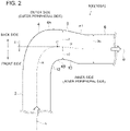
- FIG. 2 is a schematic diagram showing the shape of a bend pipe 100 (100A) according to an embodiment, as seen from the direction I.
- FIG. 3 is a schematic diagram showing the shape of a bend pipe 100 (100B) according to an embodiment, as seen from the direction I.
- FIG. 4 is a schematic diagram showing the shape of a bend pipe 100 (100C) according to an embodiment, as seen from the direction I.
- the side surface 4A of the outer side in the bend direction (the outer side with respect to the curvature radius) of the bend pipe portion 4 includes an outer inclined surface 8 inclined so that the distance d1 from the line M decreases toward the downstream side, on the back side of the line M.
- the direction E of a flow after passing the bend pipe portion 4 is inclined from the line M so as to move inward in the bend direction of the bend pipe 100 toward the downstream side.
- the flow moving in the direction E it is possible to suppress development of a separation flow that occurs in the region on the inner side of the bend direction of the bend pipe 100 by quickly making a separation flow K re-adhere to the inner side, or to suppress occurrence itself of the separation flow K. While an effect to suppress a separation flow is described in FIG. 5 referring to the bend pipe shape shown in FIG. 2 as an example, the same effect can be achieved by the bend pipe shape shown in FIGs. 3 and 4 having the outer inclined surface 8.
- the maximum value ⁇ 1 of the inclination angle formed between the outer inclined surface 8 and the line parallel to the line M is not smaller than 10°. Accordingly, it is possible to increase the inclination of the direction E of the flow after passing the bend pipe portion 4 from the above described line M to some extent, and thus it is possible to suppress development or occurrence of a separation flow in the inner region with respect to the bend direction of the bend pipe 100 with a high effectiveness.
- the pipe axial center line H of the bend pipe portion 4 includes a back-side eccentric portion Hr offset from the line M toward the back side. Accordingly, it is possible to increase the inclination of the direction E of the flow after passing the bend pipe portion 4 from the above described line M more easily, and thus it is possible to suppress development or occurrence of a separation flow in the inner region with respect to the bend direction of the bend pipe 100.
- the distance ⁇ 1 between the line M and a position P on the back-side eccentric portion Hr farthest from the line M toward the back side and the diameter De of the outlet pipe portion 6 satisfy ⁇ 1 ⁇ 0.1De. Accordingly, it is possible to increase the inclination of the direction E of the flow after passing the bend pipe portion 4 from the above described line M to some extent, and thus it is possible to suppress development or occurrence of a separation flow in the inner region with respect to the bend direction of the bend pipe 100 with a high effectiveness.
- the side surface 4B on the inner side with respect to the bend direction of the bend pipe portion 4 may include an inclined surface 12 whose distance d2 from the line M decreases toward the downstream side, and an inclined surface 10 disposed on the downstream side of the inclined surface 12, whose distance d2 from the line M increases toward the downstream side.
- the side surface 4B on the inner side with respect to the bend direction of the bend pipe portion 4 may include an inclined surface 12 whose distance d2 from the line M decreases toward the downstream side, and a non-inclined surface 14 disposed on the downstream side of the inclined surface 12, whose distance d2 from the line M is constant regardless of the position in the flow direction.
- FIG. 6 is a diagram showing a relationship between a pipe axial directional position 'm' and a flow-passage cross-sectional area A of the bend pipe 100 shown in FIG. 3 .
- the flow-passage cross-sectional area in at least one section of the bend pipe portion 4 may be greater than each of the flow-passage cross-sectional area A1 of the inlet pipe portion 2 and the flow-passage cross-sectional area A3 of the outlet pipe portion 6.
- the pressure loss of a fluid in a pipe passage increases in proportion to square of velocity of the fluid.
- the side surface 4B on the inner side with respect to the bend direction of the bend pipe portion 4 may include an inner inclined surface 16 whose distance d2 from the line M decreases toward the downstream side, disposed downstream of the outer inclined surface 8.
- the inner inclined surface 16 is formed continuously on the downstream side of the inclined surface 10 described above.
- the maximum value ⁇ 1 of the inclination angle formed by the outer inclined surface 8 with a line parallel to the line M and the maximum value ⁇ 2 of the inclination angle formed by the inner inclined surface 16 with a line parallel to the line M may satisfy ⁇ 1 ⁇ 2. Accordingly, it is possible to suppress separation effectively over a broad range on the inner side with respect to the bend direction of the bend pipe 100.
- the pipe axial center line H of the bend pipe portion 4 includes a front-side eccentric portion Hf offset from the line M toward the front side, on the downstream side of the back-side eccentric portion Hr. Accordingly, as shown in FIG. 9 , the flow from the bend pipe portion 4 to the outlet pipe portion 6 curves along the inner inclined surface, and it is possible to suppress a partial reverse flow and local separation as described above.
- the distance ⁇ 1 between the line M and a position P on the back-side eccentric portion Hr farthest from the line M toward the back side and the distance ⁇ 2 between the line M and a position Q on the front-side eccentric portion Hf farthest from the line M toward the front side may satisfy ⁇ 1 ⁇ 2. Accordingly, it is possible to suppress separation effectively over a broad range on the inner side with respect to the bend direction of the bend pipe 100.
- FIG. 10 is a diagram showing a relationship between a pipe axial directional position 'm' and a flow-passage cross-sectional area A of the bend pipe 100 shown in FIG. 4 .
- the flow-passage cross-sectional area in at least one section of the bend pipe portion 4 is greater than each of the flow-passage cross-sectional area A1 of the inlet pipe portion 2 and the flow-passage cross-sectional area A3 of the outlet pipe portion 6. Furthermore, in the embodiment shown in FIG. 10 , the flow-passage cross-sectional area of the bend pipe portion 4 reaches the local maximum value A4 at the pipe axial directional position 'm4' on the downstream side of the pipe axial directional position 'm2' at which the flow-passage cross-sectional area of the bend pipe portion 4 reaches its maximum value A2. With the above configuration, it is possible to suppress separation over a broad range on the inner side with respect to the bend direction of the bend pipe 100, and reduce pressure loss.
- FIG. 11 is a diagram showing an example of a flow-passage cross-sectional shape of the bend pipe portion 4 shown in FIGs. 2 to 4 not falling under claim 1.
- FIG. 12 is a diagram showing an example of a flow-passage cross-sectional shape of the bend pipe portion 4 shown in FIGs. 2 to 4 not falling under claim 1.
- FIG. 13 is a diagram showing an example of a flow-passage cross-sectional shape of the bend pipe portion 4 shown in FIGs. 2 to 4 .
- FIG. 14 is a diagram showing an example of a flow-passage cross-sectional shape of the bend pipe portion 4 shown in FIGs. 2 to 4 .
- FIG. 15 is a diagram showing an example of a flow-passage cross-sectional shape of the bend pipe portion 4 shown in FIGs. 2 to 4 .
- the flow-passage cross section of the bend pipe portion 4 may have a circular shape.
- the bend pipe portion 4 may include a cross section in which the gravity center G is positioned on the inner side, with respect to the bend direction, of the center O of the flow-passage width Wb in the direction J orthogonal to the direction I, at least in a partial section. That is, in the cross section of at least a partial section of the bend pipe portion 4, the flow-passage cross-sectional area A2out on the outer side, with respect to the bend direction, of the center O of the flow-passage width Wb may be smaller than the flow-passage cross-sectional area A2in on the inner side, with respect to the bend direction, of the center O.
- the flow is likely to deflect outward with respect to the bend direction, which may cause pressure loss.
- the bend pipe portion 4 including a cross section in which the gravity center G is positioned on the inner side, with respect to the bend direction, of the center O of the flow-passage width Wb as described above, the fluid is less likely to flow into a region on the outer side, with respect to the bend direction, of the center O of the bend pipe portion 4, while the fluid is more likely to flow into a region on the inner side, with respect to the bend direction, of the center O.
- separation is reduced, and it is possible to reduce pressure loss in the bend pipe portion 4.
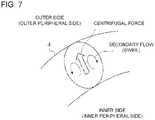
- the flow amount decreases in the region on the outer side, with respect to the bend direction, where a centrifugal force has a strong influence, and development of the secondary flow (see FIG. 7 ) is suppressed by inclination of the wall surface 18.
- the bend pipe portion 4 has a flattened shape in which the flow-passage width Wb in the direction J orthogonal to the direction I is smaller than the flow-passage width Wa in the direction I, at least in a partial section.
- the flattened shape may be an oval shape as shown in FIG. 13A, or a rectangular shape as shown in FIG. 14 , or a rectangular with rounded corners as shown in FIG. 15 .
- the flattened shape is not particularly limited, and may be a polygonal shape such as a diamond shape and a trapezoidal shape, or one of these shapes with rounded corners.
- the flow-passage width Wb in the direction J is smaller than the flow-passage width Wa in the direction I, and thereby it is possible to reduce the influence of a centrifugal force. Accordingly, it is possible to suppress a drift to a region on the outer side with respect to the bend direction, and to suppress occurrence of a secondary flow.
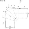
- FIG. 16 is a schematic diagram showing the shape of a bend pipe 100 according to an embodiment, as seen from the direction I.
- FIG. 17 is a diagram showing an example of cross sections S1 to S5 of the bend pipe portion 4 at a plurality of positions (pipe axial directional positions) in the flow direction shown in FIG. 16 , the example not falling under claim 1.
- FIG. 18 is a diagram showing an example of cross sections S1 to S5 of the bend pipe portion 4 at a plurality of positions (pipe axial directional positions) in the flow direction shown in FIG. 16 , the example not falling under claim 1.
- the cross sections S1 to S5 are cross sections as seen from the downstream side in the flow direction.
- the vertex position V at which the flow-passage width reaches its maximum in each of the cross sections S1 to S5 of the bend pipe portion 4 may be constant regardless of the position in the flow direction. Accordingly, it is possible to form the above described outer inclined surface 8 with a simple shape.
- the vertex position V at which the flow-passage width in each cross section of the bend pipe portion 4 reaches its maximum may shift along the rotational direction C of the flow about the axis toward the downstream side. Accordingly, even in a case where a flow that flows from the inlet pipe portion 2 originally has a rotation component, it is possible to suppress occurrence of separation effectively in a region on the inner side with respect to the bend direction of the bend pipe 100.
- the bend pipe 100 described above may be applied to an inlet pipe 22 (intake chamber) of a turbine 20 as a fluid machine. That is, as shown in FIG. 20 , in the turbine 20 including an impeller wheel 24, a turbine casing 26 covering the impeller wheel 24, and an inlet pipe 22 connected to the upstream side of the turbine casing 26 for guiding a fluid to the impeller wheel 24, the inlet pipe 22 may be the bend pipe 100.
- the bend pipe 100 described above may be applied to an outlet pipe 28 (exhaust chamber) of a turbine 20 as a fluid machine. That is, as shown in FIG. 21 , in the turbine 20 including an impeller wheel 24, a turbine casing 26 covering the impeller wheel 24, and an outlet pipe 28 connected to the downstream side of the turbine casing 26 for discharging a fluid after passing through the impeller wheel 24, the outlet pipe 28 may be the bend pipe 100.
- the bend pipe 100 described above may be applied to an inlet pipe 32 (intake chamber) of an axial flow compressor 30 serving as a fluid machine. That is, as shown in FIG. 22 , in the axial flow compressor 30 including an impeller wheel 34, a compressor casing 36 covering the impeller wheel 34, and an inlet pipe 32 connected to the upstream side of the compressor casing 36 for guiding a fluid to the impeller wheel 34, the inlet pipe 32 may be the bend pipe 100.
- the bend pipe 100 described above may be applied to an outlet pipe 38 (exhaust chamber) of an axial flow compressor 30 serving as a fluid machine. That is, as shown in FIG. 23 , in the axial flow compressor 30 including an impeller wheel 34, a compressor casing 36 covering the impeller wheel 34, and an outlet pipe 38 connected to the downstream side of the compressor casing 36 for discharging a fluid after passing through the impeller wheel 34, the outlet pipe 38 may be the bend pipe 100.
- the bend pipe 100 described above may be applied to an inlet pipe 42 of a centrifugal compressor 40 serving as a fluid machine. That is, as shown in FIG. 24 , in the centrifugal compressor 40 including an impeller wheel 44, a compressor casing 46 covering the impeller wheel 44, and an inlet pipe 42 connected to the upstream side of the compressor casing 46 for guiding a fluid to the impeller wheel 44, the inlet pipe 42 may be the bend pipe 100.
- the bend pipe 100 described above may be applied to an outlet pipe 48 (discharge scroll) of a centrifugal compressor 40 serving as a fluid machine. That is, as shown in FIG. 25 , in the centrifugal compressor 40 including an impeller wheel 44, a compressor casing 46 (see FIG. 24 ) covering the impeller wheel 44, and an outlet pipe 48 connected to the downstream side of the compressor casing 46 for discharging a fluid after passing through the impeller wheel 44, the outlet pipe 48 may be the bend pipe 100.
Description
- The present disclosure relates to a bend pipe and a fluid machine comprising the same.
- For instance, an inlet pipe and an outlet pipe of a fluid machine such as a turbine and a compressor may include a bend pipe for changing the flow direction of a fluid, for the sake of layout of the apparatus.
- As shown in
FIG. 26 , as a fluid flows through a bend pipe, the fluid may drift outward in the bend direction (outward with respect to the curvature radius) due to a centrifugal force, and separation may occur on the inner side in the bend direction (inner side with respect to the curvature radius). When such separation occurs, pressure loss occurs and the efficiency of the system decreases, with inflow of a flow deflected toward a device provided on the downstream side. Accordingly, the separation may cause deterioration of the efficiency of the device. -
Patent Document 1 focuses on occurrence of outward drift in the bend direction at the outlet of the bend portion (bend pipe portion) of the bend pipe, and discloses, as shown inFIG. 27A , eccentrically forming the joint line between the inlet pipe portion (upper portion draft) and the bend portion of the bend pipe outward in the bend direction. Accordingly, the velocity of the outward flow in the bend direction of the bend pipe is reduced, so as to achieve a uniform velocity distribution. - Patent Document 1:
JP2006-307740A -
US 2,837,810 A discloses features falling under the preamble ofclaim 1.WO 98/15769 A1 WO 00/17562 A1 -
WO 2009/127192 A1 discloses a flow-optimized pipe elbow. - While the bend pipe disclosed in
Patent Document 1 has an effect to reduce the velocity of a flow on the outer side in the bend direction of the bend pipe, a thick boundary layer develops from the vicinity of the inlet of the bend portion at the inner side of the bend direction as shown inFIG. 27B , which is likely to cause separation (reverse flow) midway in the bend portion. That is, in the bend pipe disclosed inPatent Document 1, the effect to suppress occurrence of separation on the inner region in the bend direction is limited. - In view of the above, an object of at least one embodiment of the present invention is to provide a bend pipe and a fluid machine including the same, whereby it is possible to suppress occurrence of separation in a region on the inner side in the bend direction.
- The invention is defined by
claim 1. - (1) A bend pipe for supplying a fluid to a fluid machine or discharging the fluid from the fluid machine, according to at least one embodiment of the present invention, includes: an inlet pipe portion having a linear shape; a bend pipe portion connected to a downstream end of the inlet pipe portion and configured to change a flow direction of the fluid; and an outlet pipe portion having a linear shape connected to a downstream end of the bend pipe portion. Provided that: a line including a pipe axial center line of the inlet pipe portion and an extension line thereof is defined as a line L; a line including a pipe axial line of the outlet pipe portion and an extension line thereof is defined as a line M; and a direction parallel to an intersection line formed by a plane orthogonal to the line L and a plane orthogonal to the line M is defined as a direction I, and when, as seen from the direction I, a side of the line M on which the inlet pipe portion exists is defined as a front side and a side of the line M on which the inlet pipe portion does not exist is defined as a back side, a side surface on an outer side with respect to a bend direction of the bend pipe portion includes an outer inclined surface on the back side of the line M, the outer inclined surface being inclined so that a distance from the line M decreases toward a downstream side.
- With the above bend pipe (1), the direction of a flow after passing the bend pipe portion is inclined from the line M so as to move inward in the bend direction of the bend pipe toward the downstream side. As a result, with the flow moving in the direction inclined as described above, it is possible to suppress development of a separation flow that occurs in the region on the inner side of the bend direction of the bend pipe by quickly making a separation flow adhere again to the inner side, or to suppress occurrence itself of the separation flow.
- (2) In some embodiments, in the above bend pipe (1), as seen from the direction I, a maximum value α1 of an inclination angle formed by the outer inclined surface with a line parallel to the line M is not smaller than 10°.
- With the bend pipe described in the above (2), it is possible to increase the inclination of the direction of the flow after passing the bend pipe portion from the line M to some extent, and thus it is possible to suppress development or occurrence of a separation flow in the inner region with respect to the bend direction of the bend pipe with a high effectiveness.
- (3) In the invention, a pipe axial center line of the bend pipe portion has a back-side eccentric portion offset from the line M toward the back side.
- With the bend pipe described in the above (3), it is possible to easily increase the inclination of the direction of the flow after passing the bend pipe portion from the line M, and thus it is possible to suppress development or occurrence of a separation flow in the inner region with respect to the bend direction of the bend pipe.
- (4) In some embodiments, in the above bend pipe (3), a diameter De of the outlet pipe portion and a distance δ1 between the line M and a portion of the back-side eccentric portion farthest from the line M toward the back side satisfy δ1≥0.1De.
- With the bend pipe described in the above (4), it is possible to increase the inclination of the direction of the flow after passing the bend pipe portion from the line M to some extent, and thus it is possible to suppress development or occurrence of a separation flow in the inner region with respect to the bend direction of the bend pipe with a high effectiveness.
- (5) In some embodiments, in the bend pipe described in any one of the above (1) to (4), a flow-passage cross sectional area at least in a partial section of the bend pipe portion is greater than a flow-passage cross sectional area A1 of the inlet pipe portion, and is greater than a flow-passage cross sectional area A3 of the outlet pipe portion.
- The pressure loss of a fluid in a pipe passage increases in proportion to square of velocity of the fluid. Thus, for the bend pipe portion where a particularly large pressure loss is like to occur, it is desirable to increase the flow-passage cross-sectional area and reduce the flow velocity, to reduce pressure loss.
- In this regard, as in the above (5), with the flow-passage cross-sectional area in at least one section of the bend pipe portion being greater than each of the flow-passage cross-sectional area A1 of the inlet pipe portion and the flow-passage cross-sectional area A3 of the outlet pipe portion, the flow velocity decreases and a centrifugal force applied to the fluid is reduced, at least in the above section of the bend pipe portion. Thus, it is possible to suppress separation on the inner side with respect to the bend direction of the bend pipe.
- Furthermore, as a result of a decrease in the centrifugal force at least in a section of the bend pipe portion, deflection of a flow toward the outer side in the bend direction is reduced for the outlet pipe portion, and occurrence of a secondary flow due to the centrifugal force is also suppressed. As a result, it is possible to suppress rotation of a flow at the outlet pipe portion and the downstream side thereof, and to make the flow uniform. Thus, it is possible to suppress deterioration of efficiency of a device disposed downstream of the bend pipe.
- Furthermore, also in a case where a flow originally having a rotation component enters from the inlet pipe portion, the flow-passage cross-sectional area is increased at the bend pipe portion, and thereby the rotation component is reduced, which makes it possible to make the flow uniform and reduce pressure loss.
- (6) In some embodiments, in the bend pipe described in any one of the above (1) to (5), the bend pipe portion includes, at least in a partial section, a cross section on which a gravity center is positioned on an inner side, with respect to the bend direction, of a center of a flow passage width in a direction orthogonal to the direction I.
- Generally, in the bend pipe portion, the flow is likely to deflect outward with respect to the bend direction, which may cause pressure loss. In view of this, as in the above (6), with the bend pipe portion including a cross section in which the gravity center is positioned on the inner side, in the bend direction, of the center of the flow-passage width in the direction orthogonal to the direction I, the fluid is less likely to flow into a region on the outer side, with respect to the bend direction, of the center of the bend pipe portion, while the fluid is more likely to flow into a region on the inner side, with respect to the bend direction, of the center. As a result, separation is reduced, and it is possible to reduce pressure loss in the bend pipe portion. Furthermore, the flow amount decreases in the region on the outer side, in the bend direction, where a centrifugal force has a strong influence, and development of the secondary flow is suppressed by inclination of the wall surface.
- (7) In the invention, the bend pipe portion has, at least in a partial section, a flattened shape in which a flow passage width in a direction J orthogonal to the direction I is smaller than a flow passage width in the direction I.
- With the above bend pipe (7), the flow-passage width in the direction J, of the flow passage width of the bend pipe portion, is smaller than the flow-passage width in the direction I, and thereby it is possible to reduce the influence of a centrifugal force. Accordingly, it is possible to suppress a drift to a region on the outer side with respect to the bend direction of the bend pipe, and to suppress occurrence of a secondary flow.
- (8) In some embodiments, in the above bend pipe (7), the flattened shape is an oval shape, a rectangular shape, or a rectangular shape with four rounded corners.
- With the above bend pipe (8), it is possible to achieve the effect described in the above (7) with the bend pipe having a simple shape.
- Meanwhile, as in the above bend pipe (1), in a case where the side surface on the outer side in the bend direction of the bend pipe portion has an outer inclined surface, the flow after passing through the bend pipe portion is guided to the inner side in the bend direction, and thereby it is possible to suppress separation in the inner region. On the other hand, according to findings of the present inventors, as a part of the flow toward the inner side hits the side surface on the inner side, the part of the flow may flow backward, provoking local separation on the upstream side.
- (9) Thus, in some embodiments, in the bend pipe described in any one of the above (1) to (8), a side surface on an inner side with respect to the bend direction of the bend pipe portion includes an inner inclined surface on a downstream side of the outer inclined surface, the inner inclined surface being inclined so that a distance from the line M decreases toward a downstream side.
- With the above configuration, the bend pipe is curved so that a part of the flow from the bend pipe portion to the outlet pipe portion flows along the inner inclined surface, and it is possible to suppress a partial reverse flow and local separation as described above.
- (10) In some embodiments, in the bend pipe described in any one of the above (1) to (9), as seen from the direction I, a maximum value α1 of an inclination angle formed by the outer inclined surface with a line parallel to the line M and a maximum value α2 of an inclination angle formed by the inner inclined surface with a line parallel to the line M satisfy α1≥α2.
- With the bend pipe according to the above (10), it is possible to suppress separation effectively over a broad range on the inner side with respect to the bend direction of the bend pipe.
- (11) In some embodiments, in the above bend pipe (9) or (10), a pipe axial center line of the bend pipe portion has a back-side eccentric portion offset from the line M toward the back side and a front-side eccentric portion offset from the line M toward the front side on a downstream side of the back-side eccentric portion.
- With the above bend pipe (10), in addition to the effect described in the above (3), the bend pipe is curved so that a part of the flow from the bend pipe portion to the outlet pipe portion flows along the inner inclined surface, and it is possible to suppress a partial reverse flow and local separation as described above.
- (12) In some embodiments, in the above bend pipe (11), a distance δ1 between the line M and a portion of the back-side eccentric portion farthest from the line M toward the back side and a distance δ2 between the line M and a portion of the front-side eccentric portion farthest from the line M toward the front side satisfy δ1≥δ2.
- With the bend pipe according to the above (12), it is possible to suppress separation effectively over a broad range on the inner side with respect to the bend direction of the bend pipe.
- (13) In some embodiments, in the bend pipe described in any one of the above (1) to (11), at least in a partial section of the bend pipe portion, a vertex position at which a flow passage width of each cross section of the bend pipe portion is at a maximum is shifted about a pipe axial center line of the bend pipe portion toward a downstream side.
- With the above bend pipe (13), even in a case where a flow that flows from the inlet pipe portion originally has a rotation component, it is possible to suppress occurrence of separation effectively in a region on the inner side with respect to the bend direction of the bend pipe.
- (14) A fluid machine according to at least one embodiment of the present invention includes: an impeller wheel; a casing covering the impeller wheel; an inlet pipe connected to an upstream side of the casing, for guiding a fluid to the impeller wheel; and an outlet pipe connected to a downstream side of the casing, for discharging a fluid after passing through the impeller wheel. The inlet pipe or the outlet pipe is the bend pipe according to any one of the above (1) to (13).
- With the above fluid machine (14), the bend pipe described in any one of the above (1) to (13) is provided, and thus it is possible to suppress development or occurrence of separation in a region on the inner side with respect to the bend direction of the bend pipe. Accordingly, it is possible to improve the efficiency of the fluid machine.
- (15) In some embodiments, the above fluid machine (14) is a turbine, an axial flow compressor, or a centrifugal compressor.
- With the above fluid machine (15), the bend pipe described in any one of the above (1) to (13) is provided, and thus it is possible to suppress development or occurrence of separation in a region on the inner side with respect to the bend direction of the bend pipe. Accordingly, it is possible to improve the turbine efficiency and the compressor efficiency.
- According to at least one embodiment of the present invention, provided is a bend pipe and a fluid machine including the same, whereby it is possible to suppress occurrence of separation in a region on the inner side in the bend direction.
-
-
FIG. 1 is a schematic perspective view of abend pipe 100 according to an example not falling underclaim 1. -
FIG. 2 is a schematic diagram showing an example of the shape of a bend pipe 100 (100A) according to the invention, as seen from a direction I. -
FIG. 3 is a schematic diagram showing an example of the shape of abend pipe 100 as seen from the direction I. -
FIG. 4 is a schematic diagram showing an example of the shape of abend pipe 100 as seen from the direction I. -
FIG. 5 is a diagram for describing an effect to suppress development or occurrence of a separation flow. -
FIG. 6 is a diagram showing a relationship between a pipe axial directional position 'm' and a flow-passage cross-sectional area A of abend pipe 100 shown inFIG. 3 . -
FIG. 7 is a schematic diagram for describing the secondary flow due to a centrifugal force. -
FIG. 8 is a diagram describing occurrence of a partial reverse flow, in a configuration without an innerinclined surface 16. -
FIG. 9 is a diagram describing suppression of occurrence of a partial reverse flow, in a configuration with an innerinclined surface 16. -
FIG. 10 is a diagram showing a relationship between a pipe axial directional position 'm' and a flow-passage cross-sectional area A of abend pipe 100 shown inFIG. 4 . -
FIG. 11 is a diagram showing an example of a flow-passage cross-sectional shape of abend pipe portion 4 shown inFIGs. 2 to 4 not falling underclaim 1. -
FIG. 12 is a diagram showing an example of a flow-passage cross-sectional shape of thebend pipe portion 4 shown inFIGs. 2 to 4 not falling underclaim 1. -
FIG. 13 is a diagram showing an example of a flow-passage cross-sectional shape of thebend pipe portion 4 shown inFIGs. 2 to 4 . -
FIG. 14 is a diagram showing an example of a flow-passage cross-sectional shape of thebend pipe portion 4 shown inFIGs. 2 to 4 . -
FIG. 15 is a diagram showing an example of a flow-passage cross-sectional shape of thebend pipe portion 4 shown inFIGs. 2 to 4 . -
FIG. 16 is a diagram showing the shape of abend pipe 100 according the invention -
FIG. 17 is a diagram showing an example of cross sections S1 to S5 of abend pipe portion 4 at a plurality of positions (pipe axial directional positions) in the flow direction shown inFIG. 16 , the example not falling underclaim 1. -
FIG. 18 is a diagram showing an example of cross sections S1 to S5 of abend pipe portion 4 at a plurality of positions (pipe axial directional positions) in the flow direction shown inFIG. 16 , the example not falling underclaim 1. -
FIG. 19A is a front view showing a region of occurrence of a separation flow K in abend pipe 100, not falling underclaim 1, as seen from the upstream side of thebend pipe 100. -
FIG. 19B is a top view showing a region of occurrence of a separation flow K in abend pipe 100, not falling underclaim 1, as seen from the direction I. -
FIG. 19C is a side view showing a region of occurrence of a separation flow K in abend pipe 100, not falling underclaim 1, as seen from the downstream side of thebend pipe 100. -
FIG. 20 is a schematic configuration diagram of aturbine 20 according to the invention. -
FIG. 21 is a schematic configuration diagram of aturbine 20 according to the invention. -
FIG. 22 is a schematic configuration diagram of anaxial flow compressor 30 according to the invention. -
FIG. 23 is a schematic configuration diagram of anaxial flow compressor 30 according to the invention. -
FIG. 24 is a schematic configuration diagram of acentrifugal compressor 40 according to the invention. -
FIG. 25 is a schematic configuration diagram of acentrifugal compressor 40 according to the invention. -
FIG. 26 is a diagram for describing the problem of a typical art. -
FIG. 27A is a diagram for describing the eccentric direction of a joint line between an upper portion draft and a bend portion in a typical art. -
FIG. 27B is a diagram for describing the problem of a typical art. - Embodiments of the present invention will now be described in detail with reference to the accompanying drawings. It is intended, however, that unless particularly identified, dimensions, materials, shapes, relative positions and the like of components described in the embodiments shall be interpreted as illustrative only and not intended to limit the scope of the present invention.
- For instance, an expression of relative or absolute arrangement such as "in a direction", "along a direction", "parallel", "orthogonal", "centered", "concentric" and "coaxial" shall not be construed as indicating only the arrangement in a strict literal sense, but also includes a state where the arrangement is relatively displaced by a tolerance, or by an angle or a distance whereby it is possible to achieve the same function.
- On the other hand, an expression such as "comprise", "include", "have", "contain" and "constitute" are not intended to be exclusive of other components.
-
FIG. 1 is a schematic perspective view of abend pipe 100 according to an example not falling underclaim 1. Thebend pipe 100 is a bend pipe for supplying a fluid to a fluid machine described below or discharging the fluid from the fluid machine. The fluid flowing through thebend pipe 100 is an energy medium used in energy conversion in a fluid machine, which is, for instance a high-pressure gas or a high-pressure fluid. - As shown in
FIG. 1 , thebend pipe 100 includes aninlet pipe portion 2 having a linear shape, abend pipe portion 4 connected to adownstream end 2a of theinlet pipe portion 2 and configured to change the flow direction of the fluid, and anoutlet pipe portion 6 having a linear shape connected to adownstream end 4a of thebend pipe portion 4. - Herein, as shown in
FIG. 1 , line L refers to the line including the pipe axial center line of theinlet pipe portion 2 and the extension line thereof, line M refers to the line including the pipe axial center line of theoutlet pipe portion 6 and the extension line thereof, and direction I refers to the direction parallel to an intersection line N formed by a plane orthogonal to the line L and a plane orthogonal to the line M. If the line L and the line M are on the same plane, the direction I is the direction orthogonal to the plane including both of the line L and the line M. -
FIG. 2 is a schematic diagram showing the shape of a bend pipe 100 (100A) according to an embodiment, as seen from the direction I.FIG. 3 is a schematic diagram showing the shape of a bend pipe 100 (100B) according to an embodiment, as seen from the direction I.FIG. 4 is a schematic diagram showing the shape of a bend pipe 100 (100C) according to an embodiment, as seen from the direction I. - In some embodiments, in a view of the
bend pipe 100 seen from the direction I as shown inFIGs. 2 to 4 , provided that the front side refers to a side of the line M including theinlet pipe portion 2 and the back side refers to the other side of the line M not including theinlet pipe portion 2, theside surface 4A of the outer side in the bend direction (the outer side with respect to the curvature radius) of thebend pipe portion 4 includes an outerinclined surface 8 inclined so that the distance d1 from the line M decreases toward the downstream side, on the back side of the line M. - With this configuration, as shown in
FIG. 5 , the direction E of a flow after passing thebend pipe portion 4 is inclined from the line M so as to move inward in the bend direction of thebend pipe 100 toward the downstream side. As a result, with the flow moving in the direction E, it is possible to suppress development of a separation flow that occurs in the region on the inner side of the bend direction of thebend pipe 100 by quickly making a separation flow K re-adhere to the inner side, or to suppress occurrence itself of the separation flow K. While an effect to suppress a separation flow is described inFIG. 5 referring to the bend pipe shape shown inFIG. 2 as an example, the same effect can be achieved by the bend pipe shape shown inFIGs. 3 and4 having the outerinclined surface 8. - In some embodiments, as shown in
FIGs. 2 to 4 , as seen from the direction I, the maximum value α1 of the inclination angle formed between the outerinclined surface 8 and the line parallel to the line M is not smaller than 10°. Accordingly, it is possible to increase the inclination of the direction E of the flow after passing thebend pipe portion 4 from the above described line M to some extent, and thus it is possible to suppress development or occurrence of a separation flow in the inner region with respect to the bend direction of thebend pipe 100 with a high effectiveness. - In some embodiments, as shown in
FIGs. 2 to 4 , the pipe axial center line H of thebend pipe portion 4 includes a back-side eccentric portion Hr offset from the line M toward the back side. Accordingly, it is possible to increase the inclination of the direction E of the flow after passing thebend pipe portion 4 from the above described line M more easily, and thus it is possible to suppress development or occurrence of a separation flow in the inner region with respect to the bend direction of thebend pipe 100. - In some embodiments, as shown in
FIGs. 2 to 4 , the distance δ1 between the line M and a position P on the back-side eccentric portion Hr farthest from the line M toward the back side and the diameter De of theoutlet pipe portion 6 satisfy δ1≥0.1De. Accordingly, it is possible to increase the inclination of the direction E of the flow after passing thebend pipe portion 4 from the above described line M to some extent, and thus it is possible to suppress development or occurrence of a separation flow in the inner region with respect to the bend direction of thebend pipe 100 with a high effectiveness. - In an embodiment, as shown in
FIGs. 2 and4 for instance, theside surface 4B on the inner side with respect to the bend direction of thebend pipe portion 4 may include aninclined surface 12 whose distance d2 from the line M decreases toward the downstream side, and aninclined surface 10 disposed on the downstream side of theinclined surface 12, whose distance d2 from the line M increases toward the downstream side. - In an embodiment, as shown in
FIG. 3 for instance, theside surface 4B on the inner side with respect to the bend direction of thebend pipe portion 4 may include aninclined surface 12 whose distance d2 from the line M decreases toward the downstream side, and anon-inclined surface 14 disposed on the downstream side of theinclined surface 12, whose distance d2 from the line M is constant regardless of the position in the flow direction. -
FIG. 6 is a diagram showing a relationship between a pipe axial directional position 'm' and a flow-passage cross-sectional area A of thebend pipe 100 shown inFIG. 3 . - In an embodiment, as shown in
FIG. 6 , the flow-passage cross-sectional area in at least one section of thebend pipe portion 4 may be greater than each of the flow-passage cross-sectional area A1 of theinlet pipe portion 2 and the flow-passage cross-sectional area A3 of theoutlet pipe portion 6. - The pressure loss of a fluid in a pipe passage increases in proportion to square of velocity of the fluid. Thus, for the
bend pipe portion 4 where a particularly large pressure loss is likely to occur, it is desirable to increase the flow-passage cross-sectional area and reduce the flow velocity, to reduce pressure loss. - In this regard, as in the above, with the flow-passage cross-sectional area in at least one section of the
bend pipe portion 4 being greater than each of the flow-passage cross-sectional area A1 of theinlet pipe portion 2 and the flow-passage cross-sectional area A3 of theoutlet pipe portion 6, the flow velocity decreases and a centrifugal force applied to the fluid is reduced, at least in the above section of thebend pipe portion 4. Thus, it is possible to suppress separation on the inner side with respect to the bend direction of thebend pipe 100. - Furthermore, as a result of a decrease in the centrifugal force at least in a section of the
bend pipe portion 4, deflection of a flow toward the outer side in the bend direction is reduced for theoutlet pipe portion 6, and occurrence of a secondary flow (seeFIG. 7 ) due to the centrifugal force is also suppressed. As a result, it is possible to suppress rotation of a flow at theoutlet pipe portion 6 and the downstream side thereof, and to make the flow uniform. Thus, it is possible to suppress deterioration of efficiency of a device disposed downstream of thebend pipe 100. - Furthermore, in a case where a flow originally having a rotation component enters from the
inlet pipe portion 2, the flow-passage cross-sectional area is increased at thebend pipe portion 4, and thereby the rotation component is reduced, which makes it possible to make the flow uniform and reduce pressure loss. - Meanwhile, as described above, in a case where the
side surface 4A on the outer side in the bend direction of thebend pipe portion 4 has the outerinclined surface 8, the flow after passing through thebend pipe portion 4 is guided to the inner side in the bend direction, and thereby it is possible to suppress separation in the inner region. On the other hand, according to findings of the present inventors, as shown inFIG. 8 , a part of the flow toward the inner side hits the side surface on the inner side, and the part of the flow may flow backward, provoking local separation on the upstream side. - Thus, in an embodiment, as shown in
FIG. 4 for instance, theside surface 4B on the inner side with respect to the bend direction of thebend pipe portion 4 may include an innerinclined surface 16 whose distance d2 from the line M decreases toward the downstream side, disposed downstream of the outerinclined surface 8. In the embodiment shown in the drawing, the innerinclined surface 16 is formed continuously on the downstream side of theinclined surface 10 described above. With the above configuration, as shown inFIG. 9 , the flow from thebend pipe portion 4 to theoutlet pipe portion 6 curves along the innerinclined surface 16, and it is possible to suppress a partial reverse flow and local separation as described above. - In an embodiment, in
FIG. 4 , the maximum value α1 of the inclination angle formed by the outerinclined surface 8 with a line parallel to the line M and the maximum value α2 of the inclination angle formed by the innerinclined surface 16 with a line parallel to the line M may satisfy α1≥α2. Accordingly, it is possible to suppress separation effectively over a broad range on the inner side with respect to the bend direction of thebend pipe 100. - In an embodiment, as shown in
FIG. 4 , the pipe axial center line H of thebend pipe portion 4 includes a front-side eccentric portion Hf offset from the line M toward the front side, on the downstream side of the back-side eccentric portion Hr. Accordingly, as shown inFIG. 9 , the flow from thebend pipe portion 4 to theoutlet pipe portion 6 curves along the inner inclined surface, and it is possible to suppress a partial reverse flow and local separation as described above. - In an embodiment, as shown in
FIG. 4 , the distance δ1 between the line M and a position P on the back-side eccentric portion Hr farthest from the line M toward the back side and the distance δ2 between the line M and a position Q on the front-side eccentric portion Hf farthest from the line M toward the front side may satisfy δ1≥δ2. Accordingly, it is possible to suppress separation effectively over a broad range on the inner side with respect to the bend direction of thebend pipe 100. -
FIG. 10 is a diagram showing a relationship between a pipe axial directional position 'm' and a flow-passage cross-sectional area A of thebend pipe 100 shown inFIG. 4 . - Also in the embodiment shown in
FIG. 10 , the flow-passage cross-sectional area in at least one section of thebend pipe portion 4 is greater than each of the flow-passage cross-sectional area A1 of theinlet pipe portion 2 and the flow-passage cross-sectional area A3 of theoutlet pipe portion 6. Furthermore, in the embodiment shown inFIG. 10 , the flow-passage cross-sectional area of thebend pipe portion 4 reaches the local maximum value A4 at the pipe axial directional position 'm4' on the downstream side of the pipe axial directional position 'm2' at which the flow-passage cross-sectional area of thebend pipe portion 4 reaches its maximum value A2. With the above configuration, it is possible to suppress separation over a broad range on the inner side with respect to the bend direction of thebend pipe 100, and reduce pressure loss. -
FIG. 11 is a diagram showing an example of a flow-passage cross-sectional shape of thebend pipe portion 4 shown inFIGs. 2 to 4 not falling underclaim 1.FIG. 12 is a diagram showing an example of a flow-passage cross-sectional shape of thebend pipe portion 4 shown inFIGs. 2 to 4 not falling underclaim 1.FIG. 13 is a diagram showing an example of a flow-passage cross-sectional shape of thebend pipe portion 4 shown inFIGs. 2 to 4 .FIG. 14 is a diagram showing an example of a flow-passage cross-sectional shape of thebend pipe portion 4 shown inFIGs. 2 to 4 .FIG. 15 is a diagram showing an example of a flow-passage cross-sectional shape of thebend pipe portion 4 shown inFIGs. 2 to 4 . - In an example, as shown in
FIG. 11 , the flow-passage cross section of thebend pipe portion 4 may have a circular shape. - In an example, as shown in
FIG. 12 , thebend pipe portion 4 may include a cross section in which the gravity center G is positioned on the inner side, with respect to the bend direction, of the center O of the flow-passage width Wb in the direction J orthogonal to the direction I, at least in a partial section. That is, in the cross section of at least a partial section of thebend pipe portion 4, the flow-passage cross-sectional area A2out on the outer side, with respect to the bend direction, of the center O of the flow-passage width Wb may be smaller than the flow-passage cross-sectional area A2in on the inner side, with respect to the bend direction, of the center O. - Generally, in the bend pipe portion, the flow is likely to deflect outward with respect to the bend direction, which may cause pressure loss. In view of this, with the
bend pipe portion 4 including a cross section in which the gravity center G is positioned on the inner side, with respect to the bend direction, of the center O of the flow-passage width Wb as described above, the fluid is less likely to flow into a region on the outer side, with respect to the bend direction, of the center O of thebend pipe portion 4, while the fluid is more likely to flow into a region on the inner side, with respect to the bend direction, of the center O. As a result, separation is reduced, and it is possible to reduce pressure loss in thebend pipe portion 4. Furthermore, the flow amount decreases in the region on the outer side, with respect to the bend direction, where a centrifugal force has a strong influence, and development of the secondary flow (seeFIG. 7 ) is suppressed by inclination of thewall surface 18. - In some embodiments, as shown in
FIGs. 13 to15, thebend pipe portion 4 has a flattened shape in which the flow-passage width Wb in the direction J orthogonal to the direction I is smaller than the flow-passage width Wa in the direction I, at least in a partial section. The flattened shape may be an oval shape as shown in FIG. 13A, or a rectangular shape as shown inFIG. 14 , or a rectangular with rounded corners as shown inFIG. 15 . Furthermore, although not shown in the drawings, the flattened shape is not particularly limited, and may be a polygonal shape such as a diamond shape and a trapezoidal shape, or one of these shapes with rounded corners. - With the above configuration, the flow-passage width Wb in the direction J is smaller than the flow-passage width Wa in the direction I, and thereby it is possible to reduce the influence of a centrifugal force. Accordingly, it is possible to suppress a drift to a region on the outer side with respect to the bend direction, and to suppress occurrence of a secondary flow.
-
FIG. 16 is a schematic diagram showing the shape of abend pipe 100 according to an embodiment, as seen from the direction I.FIG. 17 is a diagram showing an example of cross sections S1 to S5 of thebend pipe portion 4 at a plurality of positions (pipe axial directional positions) in the flow direction shown inFIG. 16 , the example not falling underclaim 1.FIG. 18 is a diagram showing an example of cross sections S1 to S5 of thebend pipe portion 4 at a plurality of positions (pipe axial directional positions) in the flow direction shown inFIG. 16 , the example not falling underclaim 1. InFIGs. 17 and18 , the cross sections S1 to S5 are cross sections as seen from the downstream side in the flow direction. - In an example, as shown in
FIG. 17 , the vertex position V at which the flow-passage width reaches its maximum in each of the cross sections S1 to S5 of thebend pipe portion 4 may be constant regardless of the position in the flow direction. Accordingly, it is possible to form the above described outerinclined surface 8 with a simple shape. - Meanwhile, in a case where a flow that flows from the
inlet pipe portion 2 originally has a rotation component, as shown inFIGs. 19A to 19C , the separation flow K generated on the inner side in the bend direction of thebend pipe 100 follows a twisted trajectory along the rotational direction C of the flow. - In this case, as shown in
FIG. 18 , at least in a partial section of thebend pipe portion 4, the vertex position V at which the flow-passage width in each cross section of thebend pipe portion 4 reaches its maximum may shift along the rotational direction C of the flow about the axis toward the downstream side. Accordingly, even in a case where a flow that flows from theinlet pipe portion 2 originally has a rotation component, it is possible to suppress occurrence of separation effectively in a region on the inner side with respect to the bend direction of thebend pipe 100. - Furthermore, as shown in
FIG. 20 , thebend pipe 100 described above may be applied to an inlet pipe 22 (intake chamber) of aturbine 20 as a fluid machine. That is, as shown inFIG. 20 , in theturbine 20 including animpeller wheel 24, aturbine casing 26 covering theimpeller wheel 24, and aninlet pipe 22 connected to the upstream side of theturbine casing 26 for guiding a fluid to theimpeller wheel 24, theinlet pipe 22 may be thebend pipe 100. - Furthermore, as shown in
FIG. 21 , thebend pipe 100 described above may be applied to an outlet pipe 28 (exhaust chamber) of aturbine 20 as a fluid machine. That is, as shown inFIG. 21 , in theturbine 20 including animpeller wheel 24, aturbine casing 26 covering theimpeller wheel 24, and anoutlet pipe 28 connected to the downstream side of theturbine casing 26 for discharging a fluid after passing through theimpeller wheel 24, theoutlet pipe 28 may be thebend pipe 100. - Furthermore, as shown in
FIG. 22 , thebend pipe 100 described above may be applied to an inlet pipe 32 (intake chamber) of anaxial flow compressor 30 serving as a fluid machine. That is, as shown inFIG. 22 , in theaxial flow compressor 30 including animpeller wheel 34, acompressor casing 36 covering theimpeller wheel 34, and aninlet pipe 32 connected to the upstream side of thecompressor casing 36 for guiding a fluid to theimpeller wheel 34, theinlet pipe 32 may be thebend pipe 100. - Furthermore, as shown in
FIG. 23 , thebend pipe 100 described above may be applied to an outlet pipe 38 (exhaust chamber) of anaxial flow compressor 30 serving as a fluid machine. That is, as shown inFIG. 23 , in theaxial flow compressor 30 including animpeller wheel 34, acompressor casing 36 covering theimpeller wheel 34, and anoutlet pipe 38 connected to the downstream side of thecompressor casing 36 for discharging a fluid after passing through theimpeller wheel 34, theoutlet pipe 38 may be thebend pipe 100. - Furthermore, as shown in
FIG. 24 , thebend pipe 100 described above may be applied to aninlet pipe 42 of acentrifugal compressor 40 serving as a fluid machine. That is, as shown inFIG. 24 , in thecentrifugal compressor 40 including animpeller wheel 44, acompressor casing 46 covering theimpeller wheel 44, and aninlet pipe 42 connected to the upstream side of thecompressor casing 46 for guiding a fluid to theimpeller wheel 44, theinlet pipe 42 may be thebend pipe 100. - Furthermore, as shown in
FIG. 25 , thebend pipe 100 described above may be applied to an outlet pipe 48 (discharge scroll) of acentrifugal compressor 40 serving as a fluid machine. That is, as shown inFIG. 25 , in thecentrifugal compressor 40 including animpeller wheel 44, a compressor casing 46 (seeFIG. 24 ) covering theimpeller wheel 44, and anoutlet pipe 48 connected to the downstream side of thecompressor casing 46 for discharging a fluid after passing through theimpeller wheel 44, theoutlet pipe 48 may be thebend pipe 100. -
- 2
- Inlet pipe portion
- 2a
- Downstream end
- 4
- Bend pipe portion
- 4A
- Side surface
- 4B
- Side surface
- 4a
- Downstream end
- 6
- Outlet pipe portion
- 8
- Outer inclined surface
- 10
- Inclined surface
- 12
- Inclined surface
- 14
- Non-inclined surface
- 16
- Inner inclined surface
- 18
- Wall surface
- 20
- Turbine
- 22
- Inlet pipe
- 24
- Impeller wheel
- 26
- Turbine casing
- 28
- Outlet pipe
- 30
- Axial flow compressor
- 32
- Inlet pipe
- 34
- Impeller wheel
- 36
- Compressor casing
- 38
- Outlet pipe
- 40
- Centrifugal compressor
- 42
- Inlet pipe
- 44
- Impeller wheel
- 46
- Compressor casing
- 48
- Outlet pipe
- 100
- Bend pipe
- A
- Flow-passage cross sectional area
- A1
- Flow-passage cross sectional area
- A2
- Maximum value
- A3
- Flow-passage cross sectional area
- A2in
- Flow-passage cross sectional area
- A2out
- Flow-passage cross sectional area
- A4
- Local maximum value
- C
- Rotational direction
- De
- Diameter
- E
- Direction
- G
- Gravity center
- H
- Pipe axial center line
- Hf
- Front-side eccentric portion
- Hr
- Back-side eccentric portion
- I
- Direction
- J
- Direction
- K
- Separation flow
- L
- Line
- M
- Line
- N
- Intersection line
- O
- Center
- V
- Vertex position
- Wa
- Flow-passage width
- Wb
- Flow-passage width
- d1
- Distance
- d2
- Distance
- m
- Pipe axial directional position
- m2
- Pipe axial directional position
- m4
- Pipe axial directional position
Claims (12)
- A bend pipe (100) for supplying a fluid to a fluid machine or discharging the fluid from the fluid machine, the bend pipe comprising:an inlet pipe portion (2) having a linear shape;a bend pipe portion (4) connected to a downstream end of the inlet pipe portion (2) and configured to change a flow direction of the fluid; andan outlet pipe portion (6) having a linear shape connected to a downstream end of the bend pipe portion (4),wherein, provided that: a line including a pipe axial center line of the inlet pipe portion (2) and an extension line thereof is defined as a line L; a line including a pipe axial line of the outlet pipe portion (6) and an extension line thereof is defined as a line M; and a direction parallel to an intersection line formed by a plane orthogonal to the line L and a plane orthogonal to the line M is defined as a direction I,when, as seen from the direction I, a side of the line M on which the inlet pipe portion (2) exists is defined as a front side and a side of the line M on which the inlet pipe portion (2) does not exist is defined as a back side,a side surface on an outer side with respect to a bend direction of the bend pipe portion (4) includes an outer inclined surface (8) on the back side of the line M, the outer inclined surface (8) being inclined so that a distance from the line M decreases toward a downstream side,wherein a pipe axial center line of the bend pipe portion (4) has a back-side eccentric portion offset from the line M toward the back side, and
characterized in thatthe bend pipe portion (4) has, at least in a partial section, a flattened shape in which a flow passage width in a direction J orthogonal to the direction I is smaller than a flow passage width in the direction I. - The bend pipe according to claim 1,
wherein the flattened shape is an oval shape, a rectangular shape, or a rectangular shape with four rounded corners. - The bend pipe according to claim 1 or 2,
wherein a side surface on an inner side with respect to the bend direction of the bend pipe portion (4) includes an inner inclined surface (16) on a downstream side of the outer inclined surface (8), the inner inclined surface (16) being inclined so that a distance from the line M decreases toward a downstream side. - The bend pipe according to claim 3,
wherein, as seen from the direction I, a maximum value α1 of an inclination angle formed by the outer inclined surface (8) with a line parallel to the line M and a maximum value α2 of an inclination angle formed by the inner inclined surface (16) with a line parallel to the line M satisfy α1≥ α2. - The bend pipe according to claim 3 or 4,
wherein a pipe axial center line of the bend pipe portion (6) has a back-side eccentric portion (Hr) offset from the line M toward the back side and a front-side eccentric portion (Hr) offset from the line M toward the front side on a downstream side of the back-side eccentric portion (Hr). - The bend pipe according to claim 5,
wherein a distance δ1 between the line M and a portion of the back-side eccentric portion (Hr) farthest from the line M toward the back side and a distance δ2 between the line M and a portion of the front-side eccentric portion (Hr) farthest from the line M toward the front side satisfy δ1≥δ2. - The bend pipe according to any one of claims 1 to 6,
wherein, as seen from the direction I, a maximum value α1 of an inclination angle formed by the outer inclined surface (8) with a line parallel to the line M is not smaller than 10°. - The bend pipe according to any one of claims 1 to 7,
wherein a diameter De of the outlet pipe portion and a distance δ1 between the line M and a portion of the back-side eccentric portion (Hr) farthest from the line M toward the back side satisfy δ1≥0.1De. - The bend pipe according to any one of claims 1 to 8,
wherein a flow-passage cross sectional area at least in a partial section of the bend pipe portion (4) is greater than a flow-passage cross sectional area Al of the inlet pipe portion (2), and is greater than a flow-passage cross sectional area A3 of the outlet pipe portion (6). - The bend pipe according to any one of claims 1 to 9,
wherein, at least in a partial section of the bend pipe portion, a vertex position (V) at which a flow passage width of each cross section of the bend pipe portion (4) is at a maximum is shifted about a pipe axial center line of the bend pipe portion (4) toward a downstream side. - A fluid machine, comprising:an impeller wheel (34);a casing (46) covering the impeller wheel (34);an inlet pipe (42) connected to an upstream side of the casing (46), for guiding a fluid to the impeller wheel (34); andan outlet pipe (48) connected to a downstream side of the casing (46), for discharging a fluid after passing through the impeller wheel (34),wherein the inlet pipe (42) or the outlet pipe (48) comprises the bend pipe (100) according to any one of claims 1 to 10.
- The fluid machine according to claim 11, comprising a turbine (20), an axial flow compressor (30), or a centrifugal compressor (40).
Priority Applications (1)
| Application Number | Priority Date | Filing Date | Title |
|---|---|---|---|
| EP20182247.5A EP3736482B1 (en) | 2015-12-25 | 2015-12-25 | Bend pipe and fluid machine comprising same |
Applications Claiming Priority (3)
| Application Number | Priority Date | Filing Date | Title |
|---|---|---|---|
| EP20182247.5A EP3736482B1 (en) | 2015-12-25 | 2015-12-25 | Bend pipe and fluid machine comprising same |
| EP15911387.7A EP3369982B1 (en) | 2015-12-25 | 2015-12-25 | Bend pipe and fluid machine comprising same |
| PCT/JP2015/086279 WO2017109950A1 (en) | 2015-12-25 | 2015-12-25 | Bend pipe and fluid machine comprising same |
Related Parent Applications (2)
| Application Number | Title | Priority Date | Filing Date |
|---|---|---|---|
| EP15911387.7A Division-Into EP3369982B1 (en) | 2015-12-25 | 2015-12-25 | Bend pipe and fluid machine comprising same |
| EP15911387.7A Division EP3369982B1 (en) | 2015-12-25 | 2015-12-25 | Bend pipe and fluid machine comprising same |
Publications (2)
| Publication Number | Publication Date |
|---|---|
| EP3736482A1 EP3736482A1 (en) | 2020-11-11 |
| EP3736482B1 true EP3736482B1 (en) | 2022-06-08 |
Family
ID=59089801
Family Applications (2)
| Application Number | Title | Priority Date | Filing Date |
|---|---|---|---|
| EP15911387.7A Active EP3369982B1 (en) | 2015-12-25 | 2015-12-25 | Bend pipe and fluid machine comprising same |
| EP20182247.5A Active EP3736482B1 (en) | 2015-12-25 | 2015-12-25 | Bend pipe and fluid machine comprising same |
Family Applications Before (1)
| Application Number | Title | Priority Date | Filing Date |
|---|---|---|---|
| EP15911387.7A Active EP3369982B1 (en) | 2015-12-25 | 2015-12-25 | Bend pipe and fluid machine comprising same |
Country Status (5)
| Country | Link |
|---|---|
| US (1) | US11435020B2 (en) |
| EP (2) | EP3369982B1 (en) |
| JP (1) | JP6605041B2 (en) |
| CN (1) | CN108700241B (en) |
| WO (1) | WO2017109950A1 (en) |
Families Citing this family (2)
| Publication number | Priority date | Publication date | Assignee | Title |
|---|---|---|---|---|
| CN109282105A (en) * | 2018-11-29 | 2019-01-29 | 中国船舶重工集团公司第七0四研究所 | Ball elbow vibration damping elbow with deflector |
| CN113290169B (en) * | 2021-04-19 | 2023-08-25 | 四川川交路桥有限责任公司 | Camber arch device for processing reinforcing steel bars |
Citations (1)
| Publication number | Priority date | Publication date | Assignee | Title |
|---|---|---|---|---|
| WO2009127192A1 (en) * | 2008-04-17 | 2009-10-22 | Naber Holding Gmbh & Co. Kg | Flow-optimized pipe elbow |
Family Cites Families (14)
| Publication number | Priority date | Publication date | Assignee | Title |
|---|---|---|---|---|
| US2056782A (en) * | 1934-08-22 | 1936-10-06 | Carl H Crawford | Conduit structure bend |
| US2837810A (en) * | 1955-06-17 | 1958-06-10 | Flexonics Corp | Method of producing fittings |
| FR1278649A (en) * | 1960-10-27 | 1961-12-15 | Pipe elbow | |
| JPS59180090U (en) * | 1983-05-18 | 1984-12-01 | 積水化学工業株式会社 | curved pipe |
| JPS61215890A (en) * | 1985-03-20 | 1986-09-25 | 堀井 清之 | Bent pipe |
| JPS6439426U (en) * | 1987-09-04 | 1989-03-09 | ||
| AU4243497A (en) * | 1996-10-07 | 1998-05-05 | Fmc Corporation | Low erosive wear elbow joint design |
| US6422608B1 (en) * | 1998-09-21 | 2002-07-23 | Dong Lim Industrial Co., Ltd. | Anti-abrasion pipe fittings for high-speed particle-laden flow |
| JP4311167B2 (en) * | 2003-11-11 | 2009-08-12 | 株式会社日立プラントテクノロジー | Axial type pump |
| WO2005054737A1 (en) * | 2003-11-29 | 2005-06-16 | Swagelok Company | Fluid conduit with improved flow |
| US6951354B1 (en) | 2003-12-22 | 2005-10-04 | Pelletron Corporation | Elbow fitting for pneumatic transport system |
| JP2006307740A (en) | 2005-04-28 | 2006-11-09 | Toshiba Corp | Draft tube of hydraulic machine, and hydraulic machine |
| CN100482996C (en) * | 2005-12-29 | 2009-04-29 | 中国人民解放军总后勤部建筑工程研究所 | Water conveying pipe and manufacturing method |
| CN102971465A (en) * | 2010-06-29 | 2013-03-13 | 沃尔沃建造设备有限公司 | Waterproof grommet for a cab roof of construction machinery |
-
2015
- 2015-12-25 CN CN201580084918.1A patent/CN108700241B/en active Active
- 2015-12-25 JP JP2017557630A patent/JP6605041B2/en active Active
- 2015-12-25 WO PCT/JP2015/086279 patent/WO2017109950A1/en active Application Filing
- 2015-12-25 US US15/779,337 patent/US11435020B2/en active Active
- 2015-12-25 EP EP15911387.7A patent/EP3369982B1/en active Active
- 2015-12-25 EP EP20182247.5A patent/EP3736482B1/en active Active
Patent Citations (1)
| Publication number | Priority date | Publication date | Assignee | Title |
|---|---|---|---|---|
| WO2009127192A1 (en) * | 2008-04-17 | 2009-10-22 | Naber Holding Gmbh & Co. Kg | Flow-optimized pipe elbow |
Also Published As
| Publication number | Publication date |
|---|---|
| CN108700241B (en) | 2021-07-30 |
| EP3369982A4 (en) | 2018-10-17 |
| EP3369982A1 (en) | 2018-09-05 |
| EP3369982B1 (en) | 2022-03-09 |
| US20180306365A1 (en) | 2018-10-25 |
| JP6605041B2 (en) | 2019-11-13 |
| EP3736482A1 (en) | 2020-11-11 |
| CN108700241A (en) | 2018-10-23 |
| US11435020B2 (en) | 2022-09-06 |
| JPWO2017109950A1 (en) | 2018-06-28 |
| WO2017109950A1 (en) | 2017-06-29 |
Similar Documents
| Publication | Publication Date | Title |
|---|---|---|
| US8303258B2 (en) | Fan platform fin | |
| US7934904B2 (en) | Diffuser and exhaust system for turbine | |
| EP2476868B1 (en) | Exhaust system for steam turbine | |
| US10837297B2 (en) | Centrifugal compressor and turbocharger | |
| JP6352936B2 (en) | Centrifugal compressor with twisted return channel vanes | |
| US9863427B2 (en) | Barrel-type multistage pump | |
| US11078922B2 (en) | Scroll casing and centrifugal compressor | |
| US11149588B2 (en) | Exhaust chamber of steam turbine, flow guide for steam turbine exhaust chamber, and steam turbine | |
| US9915150B2 (en) | Turbine blade | |
| EP3736482B1 (en) | Bend pipe and fluid machine comprising same | |
| US11131217B2 (en) | Steam turbine exhaust chamber and steam turbine | |
| US10655637B2 (en) | Scroll casing and centrifugal compressor | |
| EP3736419A1 (en) | Centrifugal compressor and turbocharger | |
| JP4505523B2 (en) | Axial diffuser for centrifugal compressor | |
| EP2615263A2 (en) | Diffuser for a gas turbine | |
| JP5905059B2 (en) | Centrifugal pump | |
| US20050226722A1 (en) | Fluid flow guide element and fluid flow apparatus equipped therewith | |
| CN113767213A (en) | Centrifugal compressor and turbocharger | |
| JP2017031947A (en) | Low-pressure steam turbine structure | |
| JP5826706B2 (en) | Steam turbine |
Legal Events
| Date | Code | Title | Description |
|---|---|---|---|
| PUAI | Public reference made under article 153(3) epc to a published international application that has entered the european phase |
Free format text: ORIGINAL CODE: 0009012 |
|
| STAA | Information on the status of an ep patent application or granted ep patent |
Free format text: STATUS: REQUEST FOR EXAMINATION WAS MADE |
|
| 17P | Request for examination filed |
Effective date: 20200625 |
|
| AC | Divisional application: reference to earlier application |
Ref document number: 3369982 Country of ref document: EP Kind code of ref document: P |
|
| AK | Designated contracting states |
Kind code of ref document: A1 Designated state(s): AL AT BE BG CH CY CZ DE DK EE ES FI FR GB GR HR HU IE IS IT LI LT LU LV MC MK MT NL NO PL PT RO RS SE SI SK SM TR |
|
| STAA | Information on the status of an ep patent application or granted ep patent |
Free format text: STATUS: EXAMINATION IS IN PROGRESS |
|
| 17Q | First examination report despatched |
Effective date: 20210401 |
|
| GRAP | Despatch of communication of intention to grant a patent |
Free format text: ORIGINAL CODE: EPIDOSNIGR1 |
|
| STAA | Information on the status of an ep patent application or granted ep patent |
Free format text: STATUS: GRANT OF PATENT IS INTENDED |
|
| RAP3 | Party data changed (applicant data changed or rights of an application transferred) |
Owner name: MITSUBISHI HEAVY INDUSTRIES ENGINE & TURBOCHARGER, LTD. |
|
| INTG | Intention to grant announced |
Effective date: 20220223 |
|
| GRAS | Grant fee paid |
Free format text: ORIGINAL CODE: EPIDOSNIGR3 |
|
| GRAA | (expected) grant |
Free format text: ORIGINAL CODE: 0009210 |
|
| STAA | Information on the status of an ep patent application or granted ep patent |
Free format text: STATUS: THE PATENT HAS BEEN GRANTED |
|
| AC | Divisional application: reference to earlier application |
Ref document number: 3369982 Country of ref document: EP Kind code of ref document: P |
|
| AK | Designated contracting states |
Kind code of ref document: B1 Designated state(s): AL AT BE BG CH CY CZ DE DK EE ES FI FR GB GR HR HU IE IS IT LI LT LU LV MC MK MT NL NO PL PT RO RS SE SI SK SM TR |
|
| REG | Reference to a national code |
Ref country code: AT Ref legal event code: REF Ref document number: 1497159 Country of ref document: AT Kind code of ref document: T Effective date: 20220615 Ref country code: CH Ref legal event code: EP |
|
| REG | Reference to a national code |
Ref country code: DE Ref legal event code: R096 Ref document number: 602015079435 Country of ref document: DE |
|
| REG | Reference to a national code |
Ref country code: IE Ref legal event code: FG4D |
|
| REG | Reference to a national code |
Ref country code: LT Ref legal event code: MG9D |
|
| REG | Reference to a national code |
Ref country code: NL Ref legal event code: MP Effective date: 20220608 |
|
| PG25 | Lapsed in a contracting state [announced via postgrant information from national office to epo] |
Ref country code: SE Free format text: LAPSE BECAUSE OF FAILURE TO SUBMIT A TRANSLATION OF THE DESCRIPTION OR TO PAY THE FEE WITHIN THE PRESCRIBED TIME-LIMIT Effective date: 20220608 Ref country code: NO Free format text: LAPSE BECAUSE OF FAILURE TO SUBMIT A TRANSLATION OF THE DESCRIPTION OR TO PAY THE FEE WITHIN THE PRESCRIBED TIME-LIMIT Effective date: 20220908 Ref country code: LT Free format text: LAPSE BECAUSE OF FAILURE TO SUBMIT A TRANSLATION OF THE DESCRIPTION OR TO PAY THE FEE WITHIN THE PRESCRIBED TIME-LIMIT Effective date: 20220608 Ref country code: HR Free format text: LAPSE BECAUSE OF FAILURE TO SUBMIT A TRANSLATION OF THE DESCRIPTION OR TO PAY THE FEE WITHIN THE PRESCRIBED TIME-LIMIT Effective date: 20220608 Ref country code: GR Free format text: LAPSE BECAUSE OF FAILURE TO SUBMIT A TRANSLATION OF THE DESCRIPTION OR TO PAY THE FEE WITHIN THE PRESCRIBED TIME-LIMIT Effective date: 20220909 Ref country code: FI Free format text: LAPSE BECAUSE OF FAILURE TO SUBMIT A TRANSLATION OF THE DESCRIPTION OR TO PAY THE FEE WITHIN THE PRESCRIBED TIME-LIMIT Effective date: 20220608 Ref country code: BG Free format text: LAPSE BECAUSE OF FAILURE TO SUBMIT A TRANSLATION OF THE DESCRIPTION OR TO PAY THE FEE WITHIN THE PRESCRIBED TIME-LIMIT Effective date: 20220908 |
|
| REG | Reference to a national code |
Ref country code: AT Ref legal event code: MK05 Ref document number: 1497159 Country of ref document: AT Kind code of ref document: T Effective date: 20220608 |
|
| PG25 | Lapsed in a contracting state [announced via postgrant information from national office to epo] |
Ref country code: RS Free format text: LAPSE BECAUSE OF FAILURE TO SUBMIT A TRANSLATION OF THE DESCRIPTION OR TO PAY THE FEE WITHIN THE PRESCRIBED TIME-LIMIT Effective date: 20220608 Ref country code: LV Free format text: LAPSE BECAUSE OF FAILURE TO SUBMIT A TRANSLATION OF THE DESCRIPTION OR TO PAY THE FEE WITHIN THE PRESCRIBED TIME-LIMIT Effective date: 20220608 |
|
| PG25 | Lapsed in a contracting state [announced via postgrant information from national office to epo] |
Ref country code: NL Free format text: LAPSE BECAUSE OF FAILURE TO SUBMIT A TRANSLATION OF THE DESCRIPTION OR TO PAY THE FEE WITHIN THE PRESCRIBED TIME-LIMIT Effective date: 20220608 |
|
| PG25 | Lapsed in a contracting state [announced via postgrant information from national office to epo] |
Ref country code: SM Free format text: LAPSE BECAUSE OF FAILURE TO SUBMIT A TRANSLATION OF THE DESCRIPTION OR TO PAY THE FEE WITHIN THE PRESCRIBED TIME-LIMIT Effective date: 20220608 Ref country code: SK Free format text: LAPSE BECAUSE OF FAILURE TO SUBMIT A TRANSLATION OF THE DESCRIPTION OR TO PAY THE FEE WITHIN THE PRESCRIBED TIME-LIMIT Effective date: 20220608 Ref country code: RO Free format text: LAPSE BECAUSE OF FAILURE TO SUBMIT A TRANSLATION OF THE DESCRIPTION OR TO PAY THE FEE WITHIN THE PRESCRIBED TIME-LIMIT Effective date: 20220608 Ref country code: PT Free format text: LAPSE BECAUSE OF FAILURE TO SUBMIT A TRANSLATION OF THE DESCRIPTION OR TO PAY THE FEE WITHIN THE PRESCRIBED TIME-LIMIT Effective date: 20221010 Ref country code: ES Free format text: LAPSE BECAUSE OF FAILURE TO SUBMIT A TRANSLATION OF THE DESCRIPTION OR TO PAY THE FEE WITHIN THE PRESCRIBED TIME-LIMIT Effective date: 20220608 Ref country code: EE Free format text: LAPSE BECAUSE OF FAILURE TO SUBMIT A TRANSLATION OF THE DESCRIPTION OR TO PAY THE FEE WITHIN THE PRESCRIBED TIME-LIMIT Effective date: 20220608 Ref country code: CZ Free format text: LAPSE BECAUSE OF FAILURE TO SUBMIT A TRANSLATION OF THE DESCRIPTION OR TO PAY THE FEE WITHIN THE PRESCRIBED TIME-LIMIT Effective date: 20220608 Ref country code: AT Free format text: LAPSE BECAUSE OF FAILURE TO SUBMIT A TRANSLATION OF THE DESCRIPTION OR TO PAY THE FEE WITHIN THE PRESCRIBED TIME-LIMIT Effective date: 20220608 |
|
| PG25 | Lapsed in a contracting state [announced via postgrant information from national office to epo] |
Ref country code: PL Free format text: LAPSE BECAUSE OF FAILURE TO SUBMIT A TRANSLATION OF THE DESCRIPTION OR TO PAY THE FEE WITHIN THE PRESCRIBED TIME-LIMIT Effective date: 20220608 Ref country code: IS Free format text: LAPSE BECAUSE OF FAILURE TO SUBMIT A TRANSLATION OF THE DESCRIPTION OR TO PAY THE FEE WITHIN THE PRESCRIBED TIME-LIMIT Effective date: 20221008 |
|
| REG | Reference to a national code |
Ref country code: DE Ref legal event code: R097 Ref document number: 602015079435 Country of ref document: DE |
|
| PG25 | Lapsed in a contracting state [announced via postgrant information from national office to epo] |
Ref country code: AL Free format text: LAPSE BECAUSE OF FAILURE TO SUBMIT A TRANSLATION OF THE DESCRIPTION OR TO PAY THE FEE WITHIN THE PRESCRIBED TIME-LIMIT Effective date: 20220608 |
|
| PLBE | No opposition filed within time limit |
Free format text: ORIGINAL CODE: 0009261 |
|
| STAA | Information on the status of an ep patent application or granted ep patent |
Free format text: STATUS: NO OPPOSITION FILED WITHIN TIME LIMIT |
|
| PG25 | Lapsed in a contracting state [announced via postgrant information from national office to epo] |
Ref country code: DK Free format text: LAPSE BECAUSE OF FAILURE TO SUBMIT A TRANSLATION OF THE DESCRIPTION OR TO PAY THE FEE WITHIN THE PRESCRIBED TIME-LIMIT Effective date: 20220608 |
|
| 26N | No opposition filed |
Effective date: 20230310 |
|
| PG25 | Lapsed in a contracting state [announced via postgrant information from national office to epo] |
Ref country code: SI Free format text: LAPSE BECAUSE OF FAILURE TO SUBMIT A TRANSLATION OF THE DESCRIPTION OR TO PAY THE FEE WITHIN THE PRESCRIBED TIME-LIMIT Effective date: 20220608 |
|
| REG | Reference to a national code |
Ref country code: CH Ref legal event code: PL |
|
| GBPC | Gb: european patent ceased through non-payment of renewal fee |
Effective date: 20221225 |
|
| REG | Reference to a national code |
Ref country code: BE Ref legal event code: MM Effective date: 20221231 |
|
| PG25 | Lapsed in a contracting state [announced via postgrant information from national office to epo] |
Ref country code: LU Free format text: LAPSE BECAUSE OF NON-PAYMENT OF DUE FEES Effective date: 20221225 |
|
| PG25 | Lapsed in a contracting state [announced via postgrant information from national office to epo] |
Ref country code: LI Free format text: LAPSE BECAUSE OF NON-PAYMENT OF DUE FEES Effective date: 20221231 Ref country code: IE Free format text: LAPSE BECAUSE OF NON-PAYMENT OF DUE FEES Effective date: 20221225 Ref country code: GB Free format text: LAPSE BECAUSE OF NON-PAYMENT OF DUE FEES Effective date: 20221225 Ref country code: CH Free format text: LAPSE BECAUSE OF NON-PAYMENT OF DUE FEES Effective date: 20221231 |
|
| PG25 | Lapsed in a contracting state [announced via postgrant information from national office to epo] |
Ref country code: FR Free format text: LAPSE BECAUSE OF NON-PAYMENT OF DUE FEES Effective date: 20221231 Ref country code: BE Free format text: LAPSE BECAUSE OF NON-PAYMENT OF DUE FEES Effective date: 20221231 |
|
| PG25 | Lapsed in a contracting state [announced via postgrant information from national office to epo] |
Ref country code: IT Free format text: LAPSE BECAUSE OF FAILURE TO SUBMIT A TRANSLATION OF THE DESCRIPTION OR TO PAY THE FEE WITHIN THE PRESCRIBED TIME-LIMIT Effective date: 20220608 |
|
| PGFP | Annual fee paid to national office [announced via postgrant information from national office to epo] |
Ref country code: DE Payment date: 20231031 Year of fee payment: 9 |