EP3736424B1 - Assisted engine start bleed system - Google Patents
Assisted engine start bleed system Download PDFInfo
- Publication number
- EP3736424B1 EP3736424B1 EP20172625.4A EP20172625A EP3736424B1 EP 3736424 B1 EP3736424 B1 EP 3736424B1 EP 20172625 A EP20172625 A EP 20172625A EP 3736424 B1 EP3736424 B1 EP 3736424B1
- Authority
- EP
- European Patent Office
- Prior art keywords
- entrance point
- pressurized air
- recited
- gas turbine
- turbine engine
- Prior art date
- Legal status (The legal status is an assumption and is not a legal conclusion. Google has not performed a legal analysis and makes no representation as to the accuracy of the status listed.)
- Active
Links
Images


Classifications
-
- F—MECHANICAL ENGINEERING; LIGHTING; HEATING; WEAPONS; BLASTING
- F02—COMBUSTION ENGINES; HOT-GAS OR COMBUSTION-PRODUCT ENGINE PLANTS
- F02C—GAS-TURBINE PLANTS; AIR INTAKES FOR JET-PROPULSION PLANTS; CONTROLLING FUEL SUPPLY IN AIR-BREATHING JET-PROPULSION PLANTS
- F02C6/00—Plural gas-turbine plants; Combinations of gas-turbine plants with other apparatus; Adaptations of gas-turbine plants for special use
- F02C6/04—Gas-turbine plants providing heated or pressurised working fluid for other apparatus, e.g. without mechanical power output
- F02C6/06—Gas-turbine plants providing heated or pressurised working fluid for other apparatus, e.g. without mechanical power output providing compressed gas
- F02C6/08—Gas-turbine plants providing heated or pressurised working fluid for other apparatus, e.g. without mechanical power output providing compressed gas the gas being bled from the gas-turbine compressor
-
- F—MECHANICAL ENGINEERING; LIGHTING; HEATING; WEAPONS; BLASTING
- F02—COMBUSTION ENGINES; HOT-GAS OR COMBUSTION-PRODUCT ENGINE PLANTS
- F02C—GAS-TURBINE PLANTS; AIR INTAKES FOR JET-PROPULSION PLANTS; CONTROLLING FUEL SUPPLY IN AIR-BREATHING JET-PROPULSION PLANTS
- F02C7/00—Features, components parts, details or accessories, not provided for in, or of interest apart form groups F02C1/00 - F02C6/00; Air intakes for jet-propulsion plants
- F02C7/26—Starting; Ignition
-
- F—MECHANICAL ENGINEERING; LIGHTING; HEATING; WEAPONS; BLASTING
- F02—COMBUSTION ENGINES; HOT-GAS OR COMBUSTION-PRODUCT ENGINE PLANTS
- F02C—GAS-TURBINE PLANTS; AIR INTAKES FOR JET-PROPULSION PLANTS; CONTROLLING FUEL SUPPLY IN AIR-BREATHING JET-PROPULSION PLANTS
- F02C9/00—Controlling gas-turbine plants; Controlling fuel supply in air- breathing jet-propulsion plants
- F02C9/16—Control of working fluid flow
- F02C9/18—Control of working fluid flow by bleeding, bypassing or acting on variable working fluid interconnections between turbines or compressors or their stages
-
- F—MECHANICAL ENGINEERING; LIGHTING; HEATING; WEAPONS; BLASTING
- F05—INDEXING SCHEMES RELATING TO ENGINES OR PUMPS IN VARIOUS SUBCLASSES OF CLASSES F01-F04
- F05D—INDEXING SCHEME FOR ASPECTS RELATING TO NON-POSITIVE-DISPLACEMENT MACHINES OR ENGINES, GAS-TURBINES OR JET-PROPULSION PLANTS
- F05D2240/00—Components
- F05D2240/10—Stators
- F05D2240/12—Fluid guiding means, e.g. vanes
- F05D2240/127—Vortex generators, turbulators, or the like, for mixing
-
- F—MECHANICAL ENGINEERING; LIGHTING; HEATING; WEAPONS; BLASTING
- F05—INDEXING SCHEMES RELATING TO ENGINES OR PUMPS IN VARIOUS SUBCLASSES OF CLASSES F01-F04
- F05D—INDEXING SCHEME FOR ASPECTS RELATING TO NON-POSITIVE-DISPLACEMENT MACHINES OR ENGINES, GAS-TURBINES OR JET-PROPULSION PLANTS
- F05D2260/00—Function
- F05D2260/20—Heat transfer, e.g. cooling
- F05D2260/221—Improvement of heat transfer
- F05D2260/2212—Improvement of heat transfer by creating turbulence
-
- F—MECHANICAL ENGINEERING; LIGHTING; HEATING; WEAPONS; BLASTING
- F05—INDEXING SCHEMES RELATING TO ENGINES OR PUMPS IN VARIOUS SUBCLASSES OF CLASSES F01-F04
- F05D—INDEXING SCHEME FOR ASPECTS RELATING TO NON-POSITIVE-DISPLACEMENT MACHINES OR ENGINES, GAS-TURBINES OR JET-PROPULSION PLANTS
- F05D2260/00—Function
- F05D2260/60—Fluid transfer
- F05D2260/601—Fluid transfer using an ejector or a jet pump
-
- F—MECHANICAL ENGINEERING; LIGHTING; HEATING; WEAPONS; BLASTING
- F05—INDEXING SCHEMES RELATING TO ENGINES OR PUMPS IN VARIOUS SUBCLASSES OF CLASSES F01-F04
- F05D—INDEXING SCHEME FOR ASPECTS RELATING TO NON-POSITIVE-DISPLACEMENT MACHINES OR ENGINES, GAS-TURBINES OR JET-PROPULSION PLANTS
- F05D2260/00—Function
- F05D2260/60—Fluid transfer
- F05D2260/606—Bypassing the fluid
-
- F—MECHANICAL ENGINEERING; LIGHTING; HEATING; WEAPONS; BLASTING
- F05—INDEXING SCHEMES RELATING TO ENGINES OR PUMPS IN VARIOUS SUBCLASSES OF CLASSES F01-F04
- F05D—INDEXING SCHEME FOR ASPECTS RELATING TO NON-POSITIVE-DISPLACEMENT MACHINES OR ENGINES, GAS-TURBINES OR JET-PROPULSION PLANTS
- F05D2260/00—Function
- F05D2260/85—Starting
-
- F—MECHANICAL ENGINEERING; LIGHTING; HEATING; WEAPONS; BLASTING
- F05—INDEXING SCHEMES RELATING TO ENGINES OR PUMPS IN VARIOUS SUBCLASSES OF CLASSES F01-F04
- F05D—INDEXING SCHEME FOR ASPECTS RELATING TO NON-POSITIVE-DISPLACEMENT MACHINES OR ENGINES, GAS-TURBINES OR JET-PROPULSION PLANTS
- F05D2270/00—Control
- F05D2270/01—Purpose of the control system
- F05D2270/10—Purpose of the control system to cope with, or avoid, compressor flow instabilities
-
- F—MECHANICAL ENGINEERING; LIGHTING; HEATING; WEAPONS; BLASTING
- F05—INDEXING SCHEMES RELATING TO ENGINES OR PUMPS IN VARIOUS SUBCLASSES OF CLASSES F01-F04
- F05D—INDEXING SCHEME FOR ASPECTS RELATING TO NON-POSITIVE-DISPLACEMENT MACHINES OR ENGINES, GAS-TURBINES OR JET-PROPULSION PLANTS
- F05D2270/00—Control
- F05D2270/01—Purpose of the control system
- F05D2270/10—Purpose of the control system to cope with, or avoid, compressor flow instabilities
- F05D2270/101—Compressor surge or stall
-
- Y—GENERAL TAGGING OF NEW TECHNOLOGICAL DEVELOPMENTS; GENERAL TAGGING OF CROSS-SECTIONAL TECHNOLOGIES SPANNING OVER SEVERAL SECTIONS OF THE IPC; TECHNICAL SUBJECTS COVERED BY FORMER USPC CROSS-REFERENCE ART COLLECTIONS [XRACs] AND DIGESTS
- Y02—TECHNOLOGIES OR APPLICATIONS FOR MITIGATION OR ADAPTATION AGAINST CLIMATE CHANGE
- Y02T—CLIMATE CHANGE MITIGATION TECHNOLOGIES RELATED TO TRANSPORTATION
- Y02T50/00—Aeronautics or air transport
- Y02T50/60—Efficient propulsion technologies, e.g. for aircraft
Definitions
- the present disclosure relates to a start system for a gas turbine engine and, more particularly, to a bleed system to facilitate start thereof.
- Gas turbine engines such as those which power modern commercial and military aircraft, include a compressor section, combustor section and turbine section arranged longitudinally around the engine centerline so as to provide an annular gas flow path.
- the compressor section compresses incoming atmospheric gases that are then mixed with a combustible fuel product and burned in the combustor section to produce a high energy exhaust gas stream.
- the turbine section extracts power from the exhaust gas stream to drive the compressor section.
- the exhaust gas stream produces forward thrust as it rearwardly exits the turbine section.
- Some engines may include a fan section, which is also driven by the turbine section, to produce bypass thrust.
- a military engine may include an augmentor section, or "afterburner", that is operable to selectively increase the thrust. The increase in thrust is produced when fuel is injected into the core exhaust gases downstream of the turbine section and burned with the oxygen contained therein to generate a second combustion.
- gas turbine engines may include one or more bleed valves to bleed air away from the core flow path during start-up to thereby reduce the load required to drive the compressor.
- a system for bleeding air from a core flow path of a gas turbine engine according to one aspect of the invention is provided by claim 1.
- An optional embodiment includes that the bleed air duct is of a larger diameter than the pressurized air duct.
- An optional embodiment includes that the controller is a FADEC.
- An optional embodiment includes that the first entrance point is positioned proximate a compressor section of the gas turbine engine.
- An optional embodiment includes that the first entrance point is positioned proximate a low pressure compressor section of the gas turbine engine.
- An optional embodiment includes that the first entrance point is positioned upstream of a low pressure compressor section of the gas turbine engine.
- An optional embodiment includes that the second entrance point is positioned proximate a high pressure compressor section of the gas turbine engine.
- An optional embodiment includes that the second entrance point is positioned downstream of a high pressure compressor section of the gas turbine engine.
- An optional embodiment includes that the second entrance point is positioned proximate a P3 location within the gas turbine engine.
- An optional embodiment includes an anti-ice system in communication with the vortex tube.
- a gas turbine engine according to one aspect of the present invention is provided by claim 6.
- An optional embodiment includes that the bleed air duct is of a larger diameter than the pressurized air duct.
- a method for starting a gas turbine engine according to one aspect of the present invention is provided by claim 9.
- An optional embodiment includes communicating airflow from the vortex tube to an anti-ice system.
- An optional embodiment includes that the first entrance point is positioned upstream of a low pressure compressor section of the gas turbine engine.
- An optional embodiment includes that the second entrance point is positioned proximate a high pressure compressor section of the gas turbine engine.
- An optional embodiment includes that the second entrance point is positioned proximate a P3 location within the gas turbine engine.
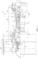
- FIG. 1 schematically illustrates a gas turbine engine 20.
- the gas turbine engine 20 is disclosed herein as a two-spool turbofan that generally incorporates a fan section 22, a compressor section 24, a combustor section 26, and a turbine section 28.
- the fan section 22 drives air along a bypass flowpath "B" while the compressor section 24 drives air along a core flowpath "C” for compression and communication into the combustor section 26, then expansion through the turbine section 28.
- a turbofan in the disclosed non-limiting embodiment, it should be appreciated that the concepts described herein may be applied to other engine architectures such as turbojets, turboshafts, and three-spool (plus fan) turbofans.
- the engine 20 generally includes a low spool 30 and a high spool 32 mounted for rotation about an engine central longitudinal axis A relative to an engine static structure 36 via several bearings 38.
- the low spool 30 generally includes an inner shaft 40 that interconnects a fan 42, a low pressure compressor (“LPC”) 44 and a low pressure turbine (“LPT”) 46.
- the inner shaft 40 drives the fan 42 directly or through a geared architecture 48 that drives the fan 42 at a lower speed than the low spool 30.
- An exemplary reduction transmission is an epicyclic transmission, such as a planetary or star gear system.
- the high spool 32 includes an outer shaft 50 that interconnects a high pressure compressor (“HPC”) 52 and high pressure turbine (“HPT”) 54.
- a combustor 56 is arranged between the high pressure compressor 52 and the high pressure turbine 54.
- the inner shaft 40 and the outer shaft 50 are concentric and rotate about the engine central longitudinal axis A which is collinear with their longitudinal axes.
- Core airflow is compressed by the LPC 44, then the HPC 52, mixed with the fuel and burned in the combustor 56, then expanded over the HPT 54 and the LPT 46 which rotationally drive the respective high spool 32 and the low spool 30 in response to the expansion.
- the shafts 40, 50 are supported at a plurality of points by bearings 38 within the static structure 36.
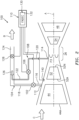
- a system 100 for bleeding air from a core flow path C of the gas turbine engine 20 includes a bleed valve 102 in a bleed duct 104, a pressurized air valve 106 in a pressurized air duct 108, and a controller 110.
- the bleed duct 104 receives bleed air from a first entrance point 112 to the core flow path C.
- the pressurized air duct 108 receives pressurized air at a pressure greater than that received into the bleed duct 104 from a second entrance point 114 to the core flow path C downstream of the first entrance point 112.
- the core flow path C includes the low pressure compressor (“LPC”) 44 and the high pressure compressor (“HPC”) 52.
- the compressor section 24 may include one or more compressor stages (each stage including a rotor section and a stator section).
- the first entrance point 112 to the core flow path C is positioned proximate the low pressure compressor ("LPC") 44, and more specifically, proximate a stage 52A of the high pressure compressor (“HPC”) 52.
- the second entrance point 114 is configured to receive the pressurized air proximate a final stage 52N of the high pressure compressor (“HPC”) 52.
- the HPC 52 is a centrifugal compressor and the first entrance point 112 is from the shrouded section of the impeller and more specifically aft of the entrance to the impeller inducer, and the second entrance point 114 is configured downstream of the impeller and upstream of the centrifugal compressor diffuser section.
- the centrifugal compressor diffuser section may include swirling vanes or an array of pipes circumferentially surrounding the impeller discharge.
- the HPC 52 is a multi-stage axial compressor and the first entrance point 112 is between the first and second stages, and the second entrance point 114 is configured at least one more stage downstream of the second stage and proximate the exit of the one more downstream stage.
- a nearly-choked flow condition means the air pressure at the second entrance point 114 is about one and one-half times the air pressure of the first entrance point 112.
- a choked flow condition means the air pressure at the second entrance point 114 is about two times the air pressure of the first entrance point 112.
- the HPC 52 is a multi-stage axial compressor and the first entrance point 112 is from between the first and second stages and the second entrance point 114 is configured at least two more stages downstream of the second stage and proximate the exit of the fourth stage.
- the HPC 52 is a multi-stage axial compressor and the first entrance point 112 is from between the second and third stages and the second entrance point 114 is configured at least two more stages downstream of the second stage and proximate the exit of the fifth stage.
- the change in the enthalpy of the core flow C imparted by each stage of the multi-stage axial compressor HPC 52 is substantially the same. As the temperature of the core flow C increases by passing through each successive stage, the stage pressure ratio of each successively aftward stage of the HPC 52 decreases and more stages are needed between the first entrance point 112 and the second entrance point 114 to result in a choked flow condition at the eductor outlet 126 within the bleed duct 104.
- the HPC 52 is a multi-stage axial compressor and the first entrance point 112 is from between the second and third stages and the second entrance point 114 is configured at least three more stages downstream of the second stage and proximate the exit of the sixth stage.
- the HPC 52 is a multi-stage axial compressor and the first entrance point 112 is from between the third and fourth stages and the second entrance point 114 is configured at the exit of the last stage 52N of the HPC 52. Locating the first entrance point 112 and the second entrance point 114 more aftward in the HPC 52 increases the density of the air flows in the bleed duct 104 and the pressurized air duct 108 and reduces the cross-sectional areas of the ducts. Locating the first entrance point 112 and the second entrance point 114 more aftward in the HPC 52 increases the temperature of the air flows in the bleed valve outlet 118 and the pressurized valve outlet 122.
- An increase to the temperature of the air flows reduces the flow Mach number of the air flows and increases heat transfer from the airflows and reduces pressure losses in the bleed duct 104 and the pressurized air duct 108. Reducing the flow Mach number of the air flows and increasing heat transfer out from the air flows reduces the frictional and thermodynamic (also known as Rayleigh flow) pressure losses in the bleed duct 104 and the pressurized air duct 108.
- the second entrance point 114 is positioned downstream of the first entrance point 112 at a relatively higher pressure location along the core flow path C.
- the second entrance point 114 may be located proximate an outer annular plenum of the combustor section 26 that operates at a pressure of approximately 500 psia (3447 kPa) and is referred to herein as P3.
- P1 represents a pressure in front of the fan section 22;
- P2 represents a pressure at the leading edge of the fan 42;
- P2.5 represents the pressure aft of the LPC 44;
- P3 represents the pressure aft of the HPC 52;
- P4 represents the pressure in the combustion chamber 66;
- P4.5 represents the pressure between the HPT 54 and the LPT 46;
- P5 represents the pressure aft of the LPT 46.
- the bleed valve 102 includes a bleed valve inlet 116 and a bleed valve outlet 118 in the bleed duct 104.
- the pressurized air valve 106 includes a pressurized inlet 120 and a pressurized valve outlet 122 in the pressurized air duct 108.
- the bleed duct 104 includes an outlet 124 into the bypass flowpath "B" and the pressurized air duct 108 includes an eductor outlet 126 within the bleed duct 104.
- One preferred location of bleed valve 102 is proximate to the first entrance point 112.
- valve 128 in outlet 124 can functionally supplement or substitute for bleed valve 102.
- valve 102 is a gate valve with low pressure losses and valve 128 is a pressure throttling valve that controls the flow in outlet 124.
- the pressurized air valve 106 is proximate to the second entrance point 114.
- valve 128 in outlet 124 can be supplementary to bleed valve 106.
- valve 106 is a gate valve with low pressure losses and valve 128 is a throttling valve that controls the flow in outlet 124.
- the pressurized air valve 106 can be proximate to the eductor and this placement reduces the length of ducting of the pressurized valve outlet 122.
- the pressurized air valve 106 must be upstream of the vortex tube 400 to regulate the heating and cooling capacity of the vortex tube by changing the pressure at the inlet to the vortex tube. Changing the pressure at the inlet to the vortex tube 400 changes the temperature difference between eductor outlet 126 and the inlet to the Anti ice unit 406.
- the eductor outlet 126 is essentially a type of pump which works on the venturi effect to facilitate pumping air through the bleed duct 104.
- the eductor outlet 126 requires only the motive fluid of the higher pressure air from the second entrance point 114 for operation.
- the bleed duct 104 is of a larger diameter (e.g., 3-4 inches or 75-100 mm) than the diameter the pressurized air duct 108 (e.g., 1-2 inches or 25-50 mm) which facilitates system installation and reduced weight.
- the controller 110 generally includes a control module 130 that executes logic 132 ( FIG. 5 ) to control operation of the bleed valve 102 and the pressurized air valve 106 to provide a stable sub-idle initial condition of air flow rate during engine starting.
- the functions of the logic 132 are disclosed in terms of functional block diagrams, and it should be appreciated that these functions may be enacted in either dedicated hardware circuitry or programmed software routines capable of execution in a microprocessor-based electronics control embodiment.
- the control module 130 may be a portion of a flight control computer, a portion of a Full Authority Digital Engine Control (FADEC), a stand-alone unit, or other system.
- the control module 130 may also communicate with a pressure sensor 140 that is used to control opening and closing of the bleed valve 102 and the pressurized air valve 106.
- a method 300 of starting a gas turbine engine includes rotating the core spool (302), by a starter motor or the like.
- the control module 130 opens the first entrance point to the core flow path C to direct bleed air (304) from the compressor section to reduce a pressure therein.
- the control module 130 opens the pressurized air valve 106 (306) directing pressurized air from the higher pressure second entrance point 114 positioned downstream thereof into the eductor outlet 126 to facilitate flow through the bleed duct 104 (308). That is, the system 100 for bleeding air induces and entrains a higher rate of bleed flow from the mid-stage of the high pressure compressor and enables a faster start.
- the combustor is ignited once the core flow path compressor section and the core flow path turbine section have reached sufficient rotational velocity for start-up.
- the system 100A includes a vortex tube 400 in the pressurized air duct 108 downstream of the pressurized air valve 106.
- the vortex tube 400 may be a mechanical device that separates the compressed gas into a relatively cold, high density flow 402 into the bleed duct 104 and a relatively hot, low density flow 404 into, for example, an anti-ice system 406.
- the system enables a stable sub-idle initial condition of air flow rate during engine starting, especially for starting very high pressure ratio high pressure compressors.
- the system is also passive and reduces mechanical complexity by avoiding auxiliary rotating turbomachinery and gearing.
Landscapes
- Engineering & Computer Science (AREA)
- Chemical & Material Sciences (AREA)
- Combustion & Propulsion (AREA)
- Mechanical Engineering (AREA)
- General Engineering & Computer Science (AREA)
- Physics & Mathematics (AREA)
- Fluid Mechanics (AREA)
- Structures Of Non-Positive Displacement Pumps (AREA)
Description
- The present disclosure relates to a start system for a gas turbine engine and, more particularly, to a bleed system to facilitate start thereof.
- Gas turbine engines, such as those which power modern commercial and military aircraft, include a compressor section, combustor section and turbine section arranged longitudinally around the engine centerline so as to provide an annular gas flow path. The compressor section compresses incoming atmospheric gases that are then mixed with a combustible fuel product and burned in the combustor section to produce a high energy exhaust gas stream. The turbine section extracts power from the exhaust gas stream to drive the compressor section. The exhaust gas stream produces forward thrust as it rearwardly exits the turbine section. Some engines may include a fan section, which is also driven by the turbine section, to produce bypass thrust. Downstream of the turbine section, a military engine may include an augmentor section, or "afterburner", that is operable to selectively increase the thrust. The increase in thrust is produced when fuel is injected into the core exhaust gases downstream of the turbine section and burned with the oxygen contained therein to generate a second combustion.
- At start-up, the turbine section of the gas turbine engine has yet to fully provide power. Thus, driving the compressor section may be more challenging than it will generally be at steady state or design conditions. Accordingly, gas turbine engines may include one or more bleed valves to bleed air away from the core flow path during start-up to thereby reduce the load required to drive the compressor.
-
- A system for bleeding air from a core flow path of a gas turbine engine according to one aspect of the invention is provided by claim 1.
- An optional embodiment includes that the bleed air duct is of a larger diameter than the pressurized air duct.
- An optional embodiment includes that the controller is a FADEC.
- An optional embodiment includes that the first entrance point is positioned proximate a compressor section of the gas turbine engine.
- An optional embodiment includes that the first entrance point is positioned proximate a low pressure compressor section of the gas turbine engine.
- An optional embodiment includes that the first entrance point is positioned upstream of a low pressure compressor section of the gas turbine engine.
- An optional embodiment includes that the second entrance point is positioned proximate a high pressure compressor section of the gas turbine engine.
- An optional embodiment includes that the second entrance point is positioned downstream of a high pressure compressor section of the gas turbine engine.
- An optional embodiment includes that the second entrance point is positioned proximate a P3 location within the gas turbine engine.
- An optional embodiment includes an anti-ice system in communication with the vortex tube.
- A gas turbine engine, according to one aspect of the present invention is provided by claim 6.
- An optional embodiment includes that the bleed air duct is of a larger diameter than the pressurized air duct.
- A method for starting a gas turbine engine according to one aspect of the present invention is provided by claim 9.
- An optional embodiment includes communicating airflow from the vortex tube to an anti-ice system.
- An optional embodiment includes that the first entrance point is positioned upstream of a low pressure compressor section of the gas turbine engine.
- An optional embodiment includes that the second entrance point is positioned proximate a high pressure compressor section of the gas turbine engine.
- An optional embodiment includes that the second entrance point is positioned proximate a P3 location within the gas turbine engine.
- The foregoing features and elements may be combined in various combinations without exclusivity, unless expressly indicated otherwise. These features and elements as well as the operation thereof will become more apparent in light of the following description and the accompanying drawings. It should be appreciated; however, the following description and drawings are intended to be exemplary in nature and non-limiting.
- Various features will become apparent to those skilled in the art from the following detailed description of the disclosed non-limiting embodiments. The drawings that accompany the detailed description can be briefly described as follows:
-
FIG. 1 is a schematic cross-section of an example gas turbine engine architecture. -
FIG. 2 is a schematic of a system for bleeding air from a core flow path of the gas turbine engine. -
FIG. 3 is a block diagram representative of logic for the system. -
FIG. 4 is a schematic of a system for bleeding air from a core flow path of the gas turbine engine. -
FIG. 5 is a block diagram representative of logic for the system. -
FIG. 1 schematically illustrates agas turbine engine 20. Thegas turbine engine 20 is disclosed herein as a two-spool turbofan that generally incorporates afan section 22, acompressor section 24, acombustor section 26, and aturbine section 28. Thefan section 22 drives air along a bypass flowpath "B" while thecompressor section 24 drives air along a core flowpath "C" for compression and communication into thecombustor section 26, then expansion through theturbine section 28. Although depicted as a turbofan in the disclosed non-limiting embodiment, it should be appreciated that the concepts described herein may be applied to other engine architectures such as turbojets, turboshafts, and three-spool (plus fan) turbofans. - The
engine 20 generally includes alow spool 30 and ahigh spool 32 mounted for rotation about an engine central longitudinal axis A relative to an enginestatic structure 36 viaseveral bearings 38. Thelow spool 30 generally includes aninner shaft 40 that interconnects afan 42, a low pressure compressor ("LPC") 44 and a low pressure turbine ("LPT") 46. Theinner shaft 40 drives thefan 42 directly or through a gearedarchitecture 48 that drives thefan 42 at a lower speed than thelow spool 30. An exemplary reduction transmission is an epicyclic transmission, such as a planetary or star gear system. - The
high spool 32 includes anouter shaft 50 that interconnects a high pressure compressor ("HPC") 52 and high pressure turbine ("HPT") 54. Acombustor 56 is arranged between thehigh pressure compressor 52 and thehigh pressure turbine 54. Theinner shaft 40 and theouter shaft 50 are concentric and rotate about the engine central longitudinal axis A which is collinear with their longitudinal axes. - Core airflow is compressed by the
LPC 44, then the HPC 52, mixed with the fuel and burned in thecombustor 56, then expanded over the HPT 54 and theLPT 46 which rotationally drive the respectivehigh spool 32 and thelow spool 30 in response to the expansion. Theshafts bearings 38 within thestatic structure 36. - With reference to
FIG. 2 , asystem 100 for bleeding air from a core flow path C of thegas turbine engine 20 includes a bleedvalve 102 in ableed duct 104, a pressurizedair valve 106 in a pressurizedair duct 108, and acontroller 110. Thebleed duct 104 receives bleed air from afirst entrance point 112 to the core flow path C. The pressurizedair duct 108 receives pressurized air at a pressure greater than that received into thebleed duct 104 from asecond entrance point 114 to the core flow path C downstream of thefirst entrance point 112. - The core flow path C includes the low pressure compressor ("LPC") 44 and the high pressure compressor ("HPC") 52. In various embodiments, the
compressor section 24 may include one or more compressor stages (each stage including a rotor section and a stator section). Thefirst entrance point 112 to the core flow path C is positioned proximate the low pressure compressor ("LPC") 44, and more specifically, proximate astage 52A of the high pressure compressor ("HPC") 52. In one embodiment, thesecond entrance point 114 is configured to receive the pressurized air proximate afinal stage 52N of the high pressure compressor ("HPC") 52. In one embodiment, the HPC 52 is a centrifugal compressor and thefirst entrance point 112 is from the shrouded section of the impeller and more specifically aft of the entrance to the impeller inducer, and thesecond entrance point 114 is configured downstream of the impeller and upstream of the centrifugal compressor diffuser section. The centrifugal compressor diffuser section may include swirling vanes or an array of pipes circumferentially surrounding the impeller discharge. In another embodiment, the HPC 52 is a multi-stage axial compressor and thefirst entrance point 112 is between the first and second stages, and thesecond entrance point 114 is configured at least one more stage downstream of the second stage and proximate the exit of the one more downstream stage. The locations of the first and second entrance points optimally result in a choked flow condition at theeductor outlet 126 within thebleed duct 104. A nearly-choked flow condition means the air pressure at thesecond entrance point 114 is about one and one-half times the air pressure of thefirst entrance point 112. A choked flow condition means the air pressure at thesecond entrance point 114 is about two times the air pressure of thefirst entrance point 112. In one embodiment theHPC 52 is a multi-stage axial compressor and thefirst entrance point 112 is from between the first and second stages and thesecond entrance point 114 is configured at least two more stages downstream of the second stage and proximate the exit of the fourth stage. In one embodiment theHPC 52 is a multi-stage axial compressor and thefirst entrance point 112 is from between the second and third stages and thesecond entrance point 114 is configured at least two more stages downstream of the second stage and proximate the exit of the fifth stage. - The change in the enthalpy of the core flow C imparted by each stage of the multi-stage
axial compressor HPC 52 is substantially the same. As the temperature of the core flow C increases by passing through each successive stage, the stage pressure ratio of each successively aftward stage of theHPC 52 decreases and more stages are needed between thefirst entrance point 112 and thesecond entrance point 114 to result in a choked flow condition at theeductor outlet 126 within thebleed duct 104. In another embodiment theHPC 52 is a multi-stage axial compressor and thefirst entrance point 112 is from between the second and third stages and thesecond entrance point 114 is configured at least three more stages downstream of the second stage and proximate the exit of the sixth stage. In another embodiment theHPC 52 is a multi-stage axial compressor and thefirst entrance point 112 is from between the third and fourth stages and thesecond entrance point 114 is configured at the exit of thelast stage 52N of theHPC 52. Locating thefirst entrance point 112 and thesecond entrance point 114 more aftward in theHPC 52 increases the density of the air flows in thebleed duct 104 and thepressurized air duct 108 and reduces the cross-sectional areas of the ducts. Locating thefirst entrance point 112 and thesecond entrance point 114 more aftward in theHPC 52 increases the temperature of the air flows in thebleed valve outlet 118 and thepressurized valve outlet 122. An increase to the temperature of the air flows reduces the flow Mach number of the air flows and increases heat transfer from the airflows and reduces pressure losses in thebleed duct 104 and thepressurized air duct 108. Reducing the flow Mach number of the air flows and increasing heat transfer out from the air flows reduces the frictional and thermodynamic (also known as Rayleigh flow) pressure losses in thebleed duct 104 and thepressurized air duct 108. - The
second entrance point 114 is positioned downstream of thefirst entrance point 112 at a relatively higher pressure location along the core flow path C. In one example, thesecond entrance point 114 may be located proximate an outer annular plenum of thecombustor section 26 that operates at a pressure of approximately 500 psia (3447 kPa) and is referred to herein as P3. For example, P1 represents a pressure in front of thefan section 22; P2 represents a pressure at the leading edge of thefan 42; P2.5 represents the pressure aft of theLPC 44; P3 represents the pressure aft of theHPC 52; P4 represents the pressure in the combustion chamber 66; P4.5 represents the pressure between theHPT 54 and theLPT 46; and P5 represents the pressure aft of theLPT 46. - The
bleed valve 102 includes ableed valve inlet 116 and ableed valve outlet 118 in thebleed duct 104. Thepressurized air valve 106 includes apressurized inlet 120 and apressurized valve outlet 122 in thepressurized air duct 108. Thebleed duct 104 includes anoutlet 124 into the bypass flowpath "B" and thepressurized air duct 108 includes aneductor outlet 126 within thebleed duct 104. One preferred location ofbleed valve 102 is proximate to thefirst entrance point 112. Optionally,valve 128 inoutlet 124 can functionally supplement or substitute forbleed valve 102. Together,valve 102 is a gate valve with low pressure losses andvalve 128 is a pressure throttling valve that controls the flow inoutlet 124. As shown inFIG 2 thepressurized air valve 106 is proximate to thesecond entrance point 114. Optionally,valve 128 inoutlet 124 can be supplementary to bleedvalve 106. Together,valve 106 is a gate valve with low pressure losses andvalve 128 is a throttling valve that controls the flow inoutlet 124. As shown inFIG 2 thepressurized air valve 106 can be proximate to the eductor and this placement reduces the length of ducting of thepressurized valve outlet 122. As shown inFIG 4 , thepressurized air valve 106 must be upstream of thevortex tube 400 to regulate the heating and cooling capacity of the vortex tube by changing the pressure at the inlet to the vortex tube. Changing the pressure at the inlet to thevortex tube 400 changes the temperature difference betweeneductor outlet 126 and the inlet to theAnti ice unit 406. - The
eductor outlet 126 is essentially a type of pump which works on the venturi effect to facilitate pumping air through thebleed duct 104. Theeductor outlet 126 requires only the motive fluid of the higher pressure air from thesecond entrance point 114 for operation. In one example, thebleed duct 104 is of a larger diameter (e.g., 3-4 inches or 75-100 mm) than the diameter the pressurized air duct 108 (e.g., 1-2 inches or 25-50 mm) which facilitates system installation and reduced weight. - The
controller 110 generally includes acontrol module 130 that executes logic 132 (FIG. 5 ) to control operation of thebleed valve 102 and thepressurized air valve 106 to provide a stable sub-idle initial condition of air flow rate during engine starting. The functions of thelogic 132 are disclosed in terms of functional block diagrams, and it should be appreciated that these functions may be enacted in either dedicated hardware circuitry or programmed software routines capable of execution in a microprocessor-based electronics control embodiment. In one example, thecontrol module 130 may be a portion of a flight control computer, a portion of a Full Authority Digital Engine Control (FADEC), a stand-alone unit, or other system. Thecontrol module 130 may also communicate with apressure sensor 140 that is used to control opening and closing of thebleed valve 102 and thepressurized air valve 106. - With reference to
FIG. 3 and5 , amethod 300 of starting a gas turbine engine is disclosed. Initially, themethod 300 includes rotating the core spool (302), by a starter motor or the like. Next, thecontrol module 130 opens the first entrance point to the core flow path C to direct bleed air (304) from the compressor section to reduce a pressure therein. Next, thecontrol module 130 opens the pressurized air valve 106 (306) directing pressurized air from the higher pressuresecond entrance point 114 positioned downstream thereof into theeductor outlet 126 to facilitate flow through the bleed duct 104 (308). That is, thesystem 100 for bleeding air induces and entrains a higher rate of bleed flow from the mid-stage of the high pressure compressor and enables a faster start. Finally, the combustor is ignited once the core flow path compressor section and the core flow path turbine section have reached sufficient rotational velocity for start-up. - With reference to
FIG. 4 , thesystem 100A includes avortex tube 400 in thepressurized air duct 108 downstream of thepressurized air valve 106. Thevortex tube 400 may be a mechanical device that separates the compressed gas into a relatively cold,high density flow 402 into thebleed duct 104 and a relatively hot,low density flow 404 into, for example, ananti-ice system 406. - The system enables a stable sub-idle initial condition of air flow rate during engine starting, especially for starting very high pressure ratio high pressure compressors. The system is also passive and reduces mechanical complexity by avoiding auxiliary rotating turbomachinery and gearing.
- Although particular step sequences are shown, described, and claimed, it should be appreciated that steps may be performed in any order, separated or combined unless otherwise indicated and will still benefit from the present disclosure.
- The foregoing description is exemplary rather than defined by the limitations within. Various non-limiting embodiments are disclosed herein; however, one of ordinary skill in the art would recognize that various modifications and variations in light of the above teachings will fall within the scope of the appended claims. It is therefore to be appreciated that within the scope of the appended claims, the disclosure may be practiced other than as specifically described. For that reason, the appended claims should be studied to determine true scope and content.
Claims (13)
- A system for bleeding air from a core flow path of a gas turbine engine, comprising:a bleed valve (102) in a bleed air duct (104) configured to receive bleed air from a first entrance point (112) to the core flow path (C) into the bleed air duct (104);a pressurized air valve (106) in a pressurized air duct (108) configured to receive pressurized air from a second entrance point (114) to the core flow path (C), the pressurized air at a pressure greater than that received into the first entrance point (112); and characterised bya vortex tube (400) in communication with the pressurized air duct (108);an eductor outlet (126) from the pressurized air duct (108) located in the bleed air duct (104); anda control system (110) operable to control operation of the bleed valve (102) and the pressurized air valve (106).
- The system as recited in claim 1, wherein the controller (110) is a FADEC.
- The system as recited in claim 1 or 2, wherein the first entrance point (112) is positioned proximate a compressor section (24) of a or the gas turbine engine.
- The system as recited in claim 1, 2 or 3, wherein the first entrance point (112) is positioned proximate a low pressure compressor section (44) of a or the gas turbine engine.
- The system as recited in any preceding claim, wherein the second entrance point (114) is positioned downstream of a high pressure compressor section (52) of a or the gas turbine engine.
- A gas turbine engine, comprising:a core flow path (C) extending through the gas turbine engine; andthe system of claim 1,wherein the first entrance point (112) is proximate a low pressure compressor section (44) in the core flow path (C); andwherein the second entrance point (114) is proximate to a high pressure compressor section (52) in the core flow path (C).
- The system as recited in any preceding claim, wherein the bleed air duct (104) is of a larger diameter than the pressurized air duct (108).
- The system as recited in any preceding claim, further comprising an anti-ice system (406) in communication with the vortex tube (400).
- A method for starting a gas turbine engine comprising:rotating a core spool which drives air through a core flow path (C);opening a bleed valve (102) in a bleed air duct (104) that is in communication with the core flow path (C) at a first entrance point (112);opening a pressurized air valve (106) in a pressurized air duct (108) that is in communication with the core flow path (C) at a second entrance point (114) downstream of the first entrance point (112); characterised bycommunicating the pressurized airflow through a vortex tube (400) in communication with the pressurized air duct (108); andcommunicating pressurized air from an eductor outlet (126) from the pressurized air duct (108) into the bleed duct (104).
- The method as recited in claim 9, further comprising communicating airflow from the vortex tube (400) to an anti-ice system (406).
- The system as recited in any of claims 1-8 or the method as recited in any of claims 9-10, wherein the first entrance point (112) is positioned upstream of a low pressure compressor section (44) of a or the gas turbine engine.
- The system as recited in any of claims 1-8 or 11, or the method as recited in any of claims 9-11, wherein the second entrance point (114) is positioned proximate a high pressure compressor section (52) of a or the gas turbine engine.
- The system as recited in any of claims 1-8 or 11-12, or the method as recited in any of claims 9-12, wherein the second entrance point (114) is positioned proximate a location aft of a or the high pressure compressor section within a or the gas turbine engine.
Applications Claiming Priority (1)
| Application Number | Priority Date | Filing Date | Title |
|---|---|---|---|
| US201962842024P | 2019-05-02 | 2019-05-02 |
Publications (2)
| Publication Number | Publication Date |
|---|---|
| EP3736424A1 EP3736424A1 (en) | 2020-11-11 |
| EP3736424B1 true EP3736424B1 (en) | 2024-10-09 |
Family
ID=70482508
Family Applications (1)
| Application Number | Title | Priority Date | Filing Date |
|---|---|---|---|
| EP20172625.4A Active EP3736424B1 (en) | 2019-05-02 | 2020-05-01 | Assisted engine start bleed system |
Country Status (2)
| Country | Link |
|---|---|
| US (1) | US12071903B2 (en) |
| EP (1) | EP3736424B1 (en) |
Families Citing this family (3)
| Publication number | Priority date | Publication date | Assignee | Title |
|---|---|---|---|---|
| US11453504B2 (en) | 2020-05-29 | 2022-09-27 | Northrop Grumman Systems Corporation | Passive heater for aircraft de-icing and method |
| CN115680903B (en) * | 2022-08-31 | 2024-05-03 | 中国航发四川燃气涡轮研究院 | Recoverable bypass bleed air control method |
| US20250382922A1 (en) * | 2024-06-18 | 2025-12-18 | Rtx Corporation | Bleeding core air from a turbine engine core flowpath |
Citations (3)
| Publication number | Priority date | Publication date | Assignee | Title |
|---|---|---|---|---|
| US6328526B1 (en) * | 1999-04-02 | 2001-12-11 | Mitsubishi Heavy Industries, Ltd. | Gas turbine starting method |
| US20170218852A1 (en) * | 2016-02-01 | 2017-08-03 | General Electric Company | Inlet bleed heat system and method of assembling the same |
| WO2017133872A1 (en) * | 2016-02-04 | 2017-08-10 | Siemens Aktiengesellschaft | Method for compensating for the axial force of a rotor of a gas turbine, and corresponding gas turbine |
Family Cites Families (23)
| Publication number | Priority date | Publication date | Assignee | Title |
|---|---|---|---|---|
| US2644315A (en) * | 1949-07-04 | 1953-07-07 | Sir George Godfrey & Partners | System for the supply of conditioned air in aircraft |
| US2839901A (en) * | 1950-05-26 | 1958-06-24 | Garrett Corp | Evaporative vortex tube refrigeration systems |
| US2786341A (en) * | 1950-06-19 | 1957-03-26 | Garrett Corp | Direct evaporative vortex tube refrigeration system |
| US2839898A (en) * | 1950-06-29 | 1958-06-24 | Garrett Corp | Multiple vortex tube generator cooling unit |
| US2839900A (en) * | 1950-08-31 | 1958-06-24 | Garrett Corp | Regenerative vortex cooling systems |
| US3026681A (en) * | 1960-10-19 | 1962-03-27 | Garrett Corp | High pressure ratio air conditioning system |
| US3361336A (en) * | 1964-06-23 | 1968-01-02 | Joseph V. Foa | Method of energy separation and apparatus for carrying out the same |
| US3973396A (en) * | 1974-10-16 | 1976-08-10 | United Turbine Ab & Co., Kommanditbolag | Gas turbine power plant |
| US4333754A (en) * | 1979-06-27 | 1982-06-08 | Vortec Corporation | Anti-icing noise-suppressing vortex tube assembly |
| US6644012B2 (en) * | 2001-11-02 | 2003-11-11 | Alston (Switzerland) Ltd | Gas turbine set |
| US7246482B2 (en) | 2004-07-16 | 2007-07-24 | Honeywell International, Inc. | Gas turbine engine bleed air power assist system and method |
| US8099966B2 (en) * | 2006-10-18 | 2012-01-24 | Textron Innovations Inc. | System and method for controlling an environment in an aircraft using a vortex cooler |
| US8955334B2 (en) | 2010-07-22 | 2015-02-17 | General Electric Company | Systems and methods for controlling the startup of a gas turbine |
| US10125724B2 (en) | 2012-01-17 | 2018-11-13 | United Technologies Corporation | Start system for gas turbine engines |
| US20130327012A1 (en) | 2012-06-11 | 2013-12-12 | General Electric Company | Gas turbine anti-icing system |
| US9611752B2 (en) | 2013-03-15 | 2017-04-04 | General Electric Company | Compressor start bleed system for a turbine system and method of controlling a compressor start bleed system |
| US9822662B2 (en) * | 2013-11-08 | 2017-11-21 | Siemens Energy, Inc. | Cooling system with compressor bleed and ambient air for gas turbine engine |
| US20150322866A1 (en) * | 2014-05-12 | 2015-11-12 | General Electric Company | Enhanced Turbine Cooling System Using a Blend of Compressor Bleed Air and Turbine Compartment Air |
| US10100744B2 (en) | 2015-06-19 | 2018-10-16 | The Boeing Company | Aircraft bleed air and engine starter systems and related methods |
| US10724443B2 (en) * | 2016-05-24 | 2020-07-28 | General Electric Company | Turbine engine and method of operating |
| JP6639338B2 (en) * | 2016-07-11 | 2020-02-05 | 三菱日立パワーシステムズ株式会社 | Gas turbine and method of operating gas turbine |
| US10670473B2 (en) * | 2017-07-25 | 2020-06-02 | Rolls-Royce North American Technologies, Inc. | Sensor with integral vortex tube for warming |
| US20190055889A1 (en) | 2017-08-17 | 2019-02-21 | United Technologies Corporation | Ducted engine compressor bleed valve architecture |
-
2020
- 2020-05-01 EP EP20172625.4A patent/EP3736424B1/en active Active
- 2020-05-01 US US16/864,881 patent/US12071903B2/en active Active
Patent Citations (4)
| Publication number | Priority date | Publication date | Assignee | Title |
|---|---|---|---|---|
| US6328526B1 (en) * | 1999-04-02 | 2001-12-11 | Mitsubishi Heavy Industries, Ltd. | Gas turbine starting method |
| EP1041290B1 (en) * | 1999-04-02 | 2005-06-01 | Mitsubishi Heavy Industries, Ltd. | Gas turbine starting method |
| US20170218852A1 (en) * | 2016-02-01 | 2017-08-03 | General Electric Company | Inlet bleed heat system and method of assembling the same |
| WO2017133872A1 (en) * | 2016-02-04 | 2017-08-10 | Siemens Aktiengesellschaft | Method for compensating for the axial force of a rotor of a gas turbine, and corresponding gas turbine |
Also Published As
| Publication number | Publication date |
|---|---|
| US20210199056A1 (en) | 2021-07-01 |
| US12071903B2 (en) | 2024-08-27 |
| EP3736424A1 (en) | 2020-11-11 |
Similar Documents
| Publication | Publication Date | Title |
|---|---|---|
| US11236675B2 (en) | Gas turbine engine with intercooled cooling air and turbine drive | |
| US11002195B2 (en) | Intercooled cooling air with auxiliary compressor control | |
| US11236639B2 (en) | Gas turbine engine and an airflow control system | |
| EP3239478B1 (en) | Combined drive for cooling air using cooling compressor and aircraft air supply pump | |
| US10119477B2 (en) | Gas turbine engine with a multi-spool driven fan | |
| EP3543508B1 (en) | Gas turbine engine with intercooled cooling air and controlled boost compressor | |
| US20160356244A1 (en) | Turbine engine with a turbo-compressor | |
| EP3736424B1 (en) | Assisted engine start bleed system | |
| US20210310422A1 (en) | Gas turbine engine with integrated air cycle machine | |
| US20160237894A1 (en) | Turbine engine with a turbo-compressor | |
| EP3056716A1 (en) | Intercooled cooling air | |
| US11286856B2 (en) | Diversion of fan air to provide cooling air for gas turbine engine | |
| EP3330515B1 (en) | Gas turbine engine | |
| EP3199779B1 (en) | Cooling air for variable geometry turbine | |
| EP3287620B1 (en) | Boost compressor for engine cooling circuit driven by low spool | |
| EP3358152B1 (en) | External mixing chamber for a gas turbine engine with cooled turbine cooling air | |
| EP3109436B1 (en) | Gas turbine engine with intercooled cooling air with improved air flow | |
| EP3647563B1 (en) | Gas turbine engine control based on characteristic of cooled air | |
| EP3179034B1 (en) | Multi-source turbine cooling air |
Legal Events
| Date | Code | Title | Description |
|---|---|---|---|
| PUAI | Public reference made under article 153(3) epc to a published international application that has entered the european phase |
Free format text: ORIGINAL CODE: 0009012 |
|
| STAA | Information on the status of an ep patent application or granted ep patent |
Free format text: STATUS: THE APPLICATION HAS BEEN PUBLISHED |
|
| AK | Designated contracting states |
Kind code of ref document: A1 Designated state(s): AL AT BE BG CH CY CZ DE DK EE ES FI FR GB GR HR HU IE IS IT LI LT LU LV MC MK MT NL NO PL PT RO RS SE SI SK SM TR |
|
| AX | Request for extension of the european patent |
Extension state: BA ME |
|
| STAA | Information on the status of an ep patent application or granted ep patent |
Free format text: STATUS: REQUEST FOR EXAMINATION WAS MADE |
|
| 17P | Request for examination filed |
Effective date: 20210510 |
|
| RBV | Designated contracting states (corrected) |
Designated state(s): AL AT BE BG CH CY CZ DE DK EE ES FI FR GB GR HR HU IE IS IT LI LT LU LV MC MK MT NL NO PL PT RO RS SE SI SK SM TR |
|
| STAA | Information on the status of an ep patent application or granted ep patent |
Free format text: STATUS: EXAMINATION IS IN PROGRESS |
|
| 17Q | First examination report despatched |
Effective date: 20220805 |
|
| RAP3 | Party data changed (applicant data changed or rights of an application transferred) |
Owner name: RTX CORPORATION |
|
| GRAP | Despatch of communication of intention to grant a patent |
Free format text: ORIGINAL CODE: EPIDOSNIGR1 |
|
| STAA | Information on the status of an ep patent application or granted ep patent |
Free format text: STATUS: GRANT OF PATENT IS INTENDED |
|
| INTG | Intention to grant announced |
Effective date: 20240430 |
|
| GRAS | Grant fee paid |
Free format text: ORIGINAL CODE: EPIDOSNIGR3 |
|
| GRAA | (expected) grant |
Free format text: ORIGINAL CODE: 0009210 |
|
| STAA | Information on the status of an ep patent application or granted ep patent |
Free format text: STATUS: THE PATENT HAS BEEN GRANTED |
|
| AK | Designated contracting states |
Kind code of ref document: B1 Designated state(s): AL AT BE BG CH CY CZ DE DK EE ES FI FR GB GR HR HU IE IS IT LI LT LU LV MC MK MT NL NO PL PT RO RS SE SI SK SM TR |
|
| REG | Reference to a national code |
Ref country code: CH Ref legal event code: EP |
|
| REG | Reference to a national code |
Ref country code: DE Ref legal event code: R096 Ref document number: 602020038911 Country of ref document: DE |
|
| REG | Reference to a national code |
Ref country code: IE Ref legal event code: FG4D |
|
| REG | Reference to a national code |
Ref country code: LT Ref legal event code: MG9D |
|
| REG | Reference to a national code |
Ref country code: NL Ref legal event code: MP Effective date: 20241009 |
|
| REG | Reference to a national code |
Ref country code: AT Ref legal event code: MK05 Ref document number: 1730815 Country of ref document: AT Kind code of ref document: T Effective date: 20241009 |
|
| PG25 | Lapsed in a contracting state [announced via postgrant information from national office to epo] |
Ref country code: NL Free format text: LAPSE BECAUSE OF FAILURE TO SUBMIT A TRANSLATION OF THE DESCRIPTION OR TO PAY THE FEE WITHIN THE PRESCRIBED TIME-LIMIT Effective date: 20241009 |
|
| PG25 | Lapsed in a contracting state [announced via postgrant information from national office to epo] |
Ref country code: NL Free format text: LAPSE BECAUSE OF FAILURE TO SUBMIT A TRANSLATION OF THE DESCRIPTION OR TO PAY THE FEE WITHIN THE PRESCRIBED TIME-LIMIT Effective date: 20241009 |
|
| PG25 | Lapsed in a contracting state [announced via postgrant information from national office to epo] |
Ref country code: IS Free format text: LAPSE BECAUSE OF FAILURE TO SUBMIT A TRANSLATION OF THE DESCRIPTION OR TO PAY THE FEE WITHIN THE PRESCRIBED TIME-LIMIT Effective date: 20250209 Ref country code: PT Free format text: LAPSE BECAUSE OF FAILURE TO SUBMIT A TRANSLATION OF THE DESCRIPTION OR TO PAY THE FEE WITHIN THE PRESCRIBED TIME-LIMIT Effective date: 20250210 Ref country code: HR Free format text: LAPSE BECAUSE OF FAILURE TO SUBMIT A TRANSLATION OF THE DESCRIPTION OR TO PAY THE FEE WITHIN THE PRESCRIBED TIME-LIMIT Effective date: 20241009 |
|
| PG25 | Lapsed in a contracting state [announced via postgrant information from national office to epo] |
Ref country code: FI Free format text: LAPSE BECAUSE OF FAILURE TO SUBMIT A TRANSLATION OF THE DESCRIPTION OR TO PAY THE FEE WITHIN THE PRESCRIBED TIME-LIMIT Effective date: 20241009 |
|
| PG25 | Lapsed in a contracting state [announced via postgrant information from national office to epo] |
Ref country code: BG Free format text: LAPSE BECAUSE OF FAILURE TO SUBMIT A TRANSLATION OF THE DESCRIPTION OR TO PAY THE FEE WITHIN THE PRESCRIBED TIME-LIMIT Effective date: 20241009 |
|
| PG25 | Lapsed in a contracting state [announced via postgrant information from national office to epo] |
Ref country code: ES Free format text: LAPSE BECAUSE OF FAILURE TO SUBMIT A TRANSLATION OF THE DESCRIPTION OR TO PAY THE FEE WITHIN THE PRESCRIBED TIME-LIMIT Effective date: 20241009 |
|
| PG25 | Lapsed in a contracting state [announced via postgrant information from national office to epo] |
Ref country code: NO Free format text: LAPSE BECAUSE OF FAILURE TO SUBMIT A TRANSLATION OF THE DESCRIPTION OR TO PAY THE FEE WITHIN THE PRESCRIBED TIME-LIMIT Effective date: 20250109 |
|
| PG25 | Lapsed in a contracting state [announced via postgrant information from national office to epo] |
Ref country code: AT Free format text: LAPSE BECAUSE OF FAILURE TO SUBMIT A TRANSLATION OF THE DESCRIPTION OR TO PAY THE FEE WITHIN THE PRESCRIBED TIME-LIMIT Effective date: 20241009 Ref country code: LV Free format text: LAPSE BECAUSE OF FAILURE TO SUBMIT A TRANSLATION OF THE DESCRIPTION OR TO PAY THE FEE WITHIN THE PRESCRIBED TIME-LIMIT Effective date: 20241009 Ref country code: GR Free format text: LAPSE BECAUSE OF FAILURE TO SUBMIT A TRANSLATION OF THE DESCRIPTION OR TO PAY THE FEE WITHIN THE PRESCRIBED TIME-LIMIT Effective date: 20250110 |
|
| PG25 | Lapsed in a contracting state [announced via postgrant information from national office to epo] |
Ref country code: PL Free format text: LAPSE BECAUSE OF FAILURE TO SUBMIT A TRANSLATION OF THE DESCRIPTION OR TO PAY THE FEE WITHIN THE PRESCRIBED TIME-LIMIT Effective date: 20241009 |
|
| PG25 | Lapsed in a contracting state [announced via postgrant information from national office to epo] |
Ref country code: RS Free format text: LAPSE BECAUSE OF FAILURE TO SUBMIT A TRANSLATION OF THE DESCRIPTION OR TO PAY THE FEE WITHIN THE PRESCRIBED TIME-LIMIT Effective date: 20250109 |
|
| PG25 | Lapsed in a contracting state [announced via postgrant information from national office to epo] |
Ref country code: SM Free format text: LAPSE BECAUSE OF FAILURE TO SUBMIT A TRANSLATION OF THE DESCRIPTION OR TO PAY THE FEE WITHIN THE PRESCRIBED TIME-LIMIT Effective date: 20241009 |
|
| PGFP | Annual fee paid to national office [announced via postgrant information from national office to epo] |
Ref country code: DE Payment date: 20250423 Year of fee payment: 6 |
|
| PG25 | Lapsed in a contracting state [announced via postgrant information from national office to epo] |
Ref country code: DK Free format text: LAPSE BECAUSE OF FAILURE TO SUBMIT A TRANSLATION OF THE DESCRIPTION OR TO PAY THE FEE WITHIN THE PRESCRIBED TIME-LIMIT Effective date: 20241009 |
|
| PGFP | Annual fee paid to national office [announced via postgrant information from national office to epo] |
Ref country code: GB Payment date: 20250423 Year of fee payment: 6 |
|
| REG | Reference to a national code |
Ref country code: DE Ref legal event code: R097 Ref document number: 602020038911 Country of ref document: DE |
|
| PG25 | Lapsed in a contracting state [announced via postgrant information from national office to epo] |
Ref country code: EE Free format text: LAPSE BECAUSE OF FAILURE TO SUBMIT A TRANSLATION OF THE DESCRIPTION OR TO PAY THE FEE WITHIN THE PRESCRIBED TIME-LIMIT Effective date: 20241009 |
|
| PGFP | Annual fee paid to national office [announced via postgrant information from national office to epo] |
Ref country code: FR Payment date: 20250424 Year of fee payment: 6 |
|
| PG25 | Lapsed in a contracting state [announced via postgrant information from national office to epo] |
Ref country code: RO Free format text: LAPSE BECAUSE OF FAILURE TO SUBMIT A TRANSLATION OF THE DESCRIPTION OR TO PAY THE FEE WITHIN THE PRESCRIBED TIME-LIMIT Effective date: 20241009 |
|
| PG25 | Lapsed in a contracting state [announced via postgrant information from national office to epo] |
Ref country code: SK Free format text: LAPSE BECAUSE OF FAILURE TO SUBMIT A TRANSLATION OF THE DESCRIPTION OR TO PAY THE FEE WITHIN THE PRESCRIBED TIME-LIMIT Effective date: 20241009 |
|
| PG25 | Lapsed in a contracting state [announced via postgrant information from national office to epo] |
Ref country code: CZ Free format text: LAPSE BECAUSE OF FAILURE TO SUBMIT A TRANSLATION OF THE DESCRIPTION OR TO PAY THE FEE WITHIN THE PRESCRIBED TIME-LIMIT Effective date: 20241009 |
|
| PG25 | Lapsed in a contracting state [announced via postgrant information from national office to epo] |
Ref country code: IT Free format text: LAPSE BECAUSE OF FAILURE TO SUBMIT A TRANSLATION OF THE DESCRIPTION OR TO PAY THE FEE WITHIN THE PRESCRIBED TIME-LIMIT Effective date: 20241009 |
|
| PLBE | No opposition filed within time limit |
Free format text: ORIGINAL CODE: 0009261 |
|
| STAA | Information on the status of an ep patent application or granted ep patent |
Free format text: STATUS: NO OPPOSITION FILED WITHIN TIME LIMIT |
|
| PG25 | Lapsed in a contracting state [announced via postgrant information from national office to epo] |
Ref country code: SE Free format text: LAPSE BECAUSE OF FAILURE TO SUBMIT A TRANSLATION OF THE DESCRIPTION OR TO PAY THE FEE WITHIN THE PRESCRIBED TIME-LIMIT Effective date: 20241009 |
|
| 26N | No opposition filed |
Effective date: 20250710 |
|
| REG | Reference to a national code |
Ref country code: CH Ref legal event code: H13 Free format text: ST27 STATUS EVENT CODE: U-0-0-H10-H13 (AS PROVIDED BY THE NATIONAL OFFICE) Effective date: 20251223 |
|
| PG25 | Lapsed in a contracting state [announced via postgrant information from national office to epo] |
Ref country code: LU Free format text: LAPSE BECAUSE OF NON-PAYMENT OF DUE FEES Effective date: 20250501 |
|
| PG25 | Lapsed in a contracting state [announced via postgrant information from national office to epo] |
Ref country code: CH Free format text: LAPSE BECAUSE OF NON-PAYMENT OF DUE FEES Effective date: 20250531 |
|
| REG | Reference to a national code |
Ref country code: BE Ref legal event code: MM Effective date: 20250531 |
|
| PG25 | Lapsed in a contracting state [announced via postgrant information from national office to epo] |
Ref country code: MC Free format text: LAPSE BECAUSE OF FAILURE TO SUBMIT A TRANSLATION OF THE DESCRIPTION OR TO PAY THE FEE WITHIN THE PRESCRIBED TIME-LIMIT Effective date: 20241009 |
|
| PG25 | Lapsed in a contracting state [announced via postgrant information from national office to epo] |
Ref country code: IE Free format text: LAPSE BECAUSE OF NON-PAYMENT OF DUE FEES Effective date: 20250501 |
|
| PG25 | Lapsed in a contracting state [announced via postgrant information from national office to epo] |
Ref country code: BE Free format text: LAPSE BECAUSE OF NON-PAYMENT OF DUE FEES Effective date: 20250531 |