EP1041290A2 - Gas turbine starting method - Google Patents
Gas turbine starting method Download PDFInfo
- Publication number
- EP1041290A2 EP1041290A2 EP00105406A EP00105406A EP1041290A2 EP 1041290 A2 EP1041290 A2 EP 1041290A2 EP 00105406 A EP00105406 A EP 00105406A EP 00105406 A EP00105406 A EP 00105406A EP 1041290 A2 EP1041290 A2 EP 1041290A2
- Authority
- EP
- European Patent Office
- Prior art keywords
- speed
- bleed valves
- gas turbine
- bleed
- compressor
- Prior art date
- Legal status (The legal status is an assumption and is not a legal conclusion. Google has not performed a legal analysis and makes no representation as to the accuracy of the status listed.)
- Granted
Links
- 238000000034 method Methods 0.000 title claims abstract description 31
- 230000000977 initiatory effect Effects 0.000 claims description 8
- 239000003570 air Substances 0.000 abstract description 41
- 239000012530 fluid Substances 0.000 abstract description 13
- 239000012080 ambient air Substances 0.000 abstract description 9
- 239000007858 starting material Substances 0.000 abstract description 9
- 230000000740 bleeding effect Effects 0.000 description 2
- 238000002485 combustion reaction Methods 0.000 description 1
- 238000010276 construction Methods 0.000 description 1
- 238000001816 cooling Methods 0.000 description 1
- 230000005284 excitation Effects 0.000 description 1
Images


Classifications
-
- F—MECHANICAL ENGINEERING; LIGHTING; HEATING; WEAPONS; BLASTING
- F02—COMBUSTION ENGINES; HOT-GAS OR COMBUSTION-PRODUCT ENGINE PLANTS
- F02C—GAS-TURBINE PLANTS; AIR INTAKES FOR JET-PROPULSION PLANTS; CONTROLLING FUEL SUPPLY IN AIR-BREATHING JET-PROPULSION PLANTS
- F02C7/00—Features, components parts, details or accessories, not provided for in, or of interest apart form groups F02C1/00 - F02C6/00; Air intakes for jet-propulsion plants
- F02C7/26—Starting; Ignition
-
- F—MECHANICAL ENGINEERING; LIGHTING; HEATING; WEAPONS; BLASTING
- F04—POSITIVE - DISPLACEMENT MACHINES FOR LIQUIDS; PUMPS FOR LIQUIDS OR ELASTIC FLUIDS
- F04D—NON-POSITIVE-DISPLACEMENT PUMPS
- F04D27/00—Control, e.g. regulation, of pumps, pumping installations or pumping systems specially adapted for elastic fluids
- F04D27/02—Surge control
- F04D27/0207—Surge control by bleeding, bypassing or recycling fluids
- F04D27/0223—Control schemes therefor
-
- F—MECHANICAL ENGINEERING; LIGHTING; HEATING; WEAPONS; BLASTING
- F04—POSITIVE - DISPLACEMENT MACHINES FOR LIQUIDS; PUMPS FOR LIQUIDS OR ELASTIC FLUIDS
- F04D—NON-POSITIVE-DISPLACEMENT PUMPS
- F04D27/00—Control, e.g. regulation, of pumps, pumping installations or pumping systems specially adapted for elastic fluids
- F04D27/02—Surge control
- F04D27/0207—Surge control by bleeding, bypassing or recycling fluids
- F04D27/023—Details or means for fluid extraction
Definitions
- the present invention relates to a gas turbine starting method, which includes to reduce an air amount to be discharged into the air and to avoid a fluid unstableness phenomenon occurring in a compressor both at the time of starting.
- Fig. 3 is a cross sectional view of one example of a gas turbine compressor in the prior art.
- numeral 50 designates a compressor
- numeral 10 designates a rotor.
- the rotor 10 has rotor vanes M1, M2, M3, M4 ....(illustration shows an example of 10 stages) fitted to an outer circumferential periphery of a rotor disc so as to be rotated together with the rotor 10.
- stator vanes C1, C2, C3, C4 .... are fitted to an inner circumferential wall of a casing 14 so that the stator vanes and the rotor vanes are arranged alternately in an axial direction of the compressor 50.
- an IGV (Inlet Guide Vane) 11 is fitted to the inner circumferential wall of the casing 14 so as to adjustable of its opening by a driver portion 12.
- Air 20 is adjusted of a flow rate by the opening of the IGV 11 to enter the compressor 50 to be compressed while flowing through between the respective stator vanes and between the rotating rotor vanes and a compressed air 21 flows out of the compressor 50 to be supplied as a gas turbine combustion air or a turbine rotor or turbine blade cooling air.
- Fig. 4 is a diagrammatic constructional view of stator vanes and their surrounding portion of the above-mentioned compressor in the prior art having five stages of variable stator vanes C1 to C5.
- an IGV 11 is provided at an inlet of a compressor 50 and stator vanes C1 to C15 are arranged, although not all the stator vanes are illustrated.
- An opening 15 is provided immediately after the fifth stage stator vane C5 so as to communicate with a piping 30.
- the piping 30 is provided at its middle way with a bleed valve 60 for bleeding a compressed air.
- an opening 16 is provided immediately after the eighth stage stator vane C8, and a piping 31 and a bleed valve 61 communicate therewith.
- an opening 17 is provided immediately after the eleventh stage stator vane C11, and a piping 32 and a bleed valve 62 communicate therewith. It is to be noted that the openings 15, 16, 17, respectively, are provided at four places on an outer circumferential periphery of a casing and four pipings each of the pipings 30, 31, 32 join together to communicate with the respective bleed valves 60, 61, 62.
- the bleed valves 60, 61, 62 are so constructed as to be either fully opened or fully closed by an ON/OFF operation.
- the IGV 11 and the stator vanes C1 to C5 are set to a predetermined opening, the bleed valves 60, 61, 62 are fully opened and air 20 is compressed.
- the compressor is operated by a drive of a starter motor.
- the bleed valves 60, 61, 62 are fully opened so that the air 20 is bled to be discharged into the ambient air for a matching of an air flow rate to the slow speed operation.
- the speed comes to 90% of a rated speed and the operation rises up, the bleed valves 60, 61, 62 are fully closed and a steady operation starts.
- a mismatching of the air flow rate occurs at the initial stage of the starting or a flow rate unstableness phenomenon occurs at the time when the bleed valves are closed while the speed is being elevated, etc. as well as the starter motor must have a large capacity in order to ensure a starting force at the time of operation start.
- the starter motor is needed to have a sufficient capacity taking account of the air flow rate to be discharged into the ambient air at the time of starting.
- the adjustment of the bleed valves to meet the air flow rate of the initial slow speed operation time and that of the compressor rated operation time is only done by the ON/OFF operation by which the bleed valves are either fully opened or fully closed, hence a phenomenon to cause an unstable fluid flow occurs at the starting time, which results in the obstruction in achieving a smooth speed elevation.
- the present invention provides methods of the following (1) to (7).
- the present invention is based on the invention (1) above.
- the compressor is driven by a starter motor.
- the IGV and the variable stator vane are set to a predetermined opening, the plurality of bleed valves are controlled to be opened or closed, so that air flow rate at the slow speed rotating time is adjusted and the speed is elevated.
- the starting operation is such that the bleed valves, which are of the type to be either opened or closed by the ON/OFF control, are fully opened until the speed comes to 90% of the rated speed and thereafter are fully closed, hence a large amount of the air is discharged into the ambient air to be wasted, which results in requiring a larger capacity of the starter motor.
- the bleed valves are of the variable type in which the opening may be varied from a fully opened position to a fully closed position during the starting time, hence the flow rate of the air to be discharged into the ambient air from the bleed valves during the starting time can be controlled, so that the air discharged in vain can be reduced and also the control of the bleed valve opening can be done so as to avoid an occurrence of the fluid unstableness phenomenon during the time of the starting.
- the bleed valve opening is controlled finely corresponding to the speed elevation such that the bleed valves are first throttled to a predetermined opening until the half way of the speed elevation and then are fully opened until immediately before the speed comes to the rated speed and thereafter are fully closed for the rated operation.
- the air discharged into the ambient air in vain can be reduced and by the bleed valve opening being controlled finely, the fluid unstableness phenomenon can be also controlled so as to be suppressed.
- the bleed valve opening is controlled finely corresponding to each range of the speed level, thereby an optimum bleed air flow rate can be obtained.
- the plurality of bleed valves are throttled differently from each other in the openings, for example, in a larger opening for the front stage bleed valves and in a smaller opening for the rear stage bleed valves, and in the invention (4) above, at least one of the plurality of bleed valves, for example, the rearmost bleed valve, is fully closed.
- the air discharged in vain can be reduced as well as by the fine control of the opening setting, an occurrence of the fluid unstableness phenomenon can be suppressed.
- the air compressed at the compressor is to be abandoned outside, as the air of the rear stages has a higher energy, it will be a larger loss if the air of the rear stages is abandoned.
- the time when the bleed valves are fully opened on the way is that when the speed exceeds about 50% of the rated speed wherein at least one of the bleed valves is different in this speed from others of the bleed valves so that variation in the air flow rate may differ from each other.
- the exhaust gas temperature becomes highest in the speed range around 50%, hence if the bleed air amount is reduced in this speed range, it will be advantageous for suppressing the temperature elevation.
- the fluid unstableness phenomenon of the compressor comes to its peak in the speed range around 60%, hence in order to increase the bleed air amount in this speed range, the opening of the bleed valves is operated on the boundary of about 50% speed. It is to be noted, however, that whether all the bleed valves are to be controlled at the same speed or at the different speeds may not be specified necessarily but may be set to various speeds.
- the time when the bleed valves are fully closed is set to the time when the speed exceeds 90% of the rated speed, hence the speed elevation from the start to the rated speed when the operation rises up can be done smoothly, excitation force acting on the vanes is suppressed and occurrence of the fluid unstableness phenomenon also is suppressed.
- the bleed valves are arranged so as to bleed the air from the front stages to the rear stages of the compressor, thereby an appropriate setting of the air bleeding can be attained.
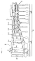
- Fig. 1 is a diagrammatic constructional view of a compressor as an embodiment for carrying out a gas turbine starting method of the present invention.
- construction of the compressor is same as that of the prior art one shown in Fig. 4 and same parts are given with same reference numerals, and a featured portion of the present invention, that is, bleed valves 1, 2, 3 and a control method by a control unit 4, will be described in detail.
- the bleed valves 1, 2, 3 are valves whose openings can be set arbitrarily, in place of the ON/OFF valves in the prior art which are either opened or closed only.
- the control unit 4 when a gas turbine is to be started, it is so set at the control unit 4 that the bleed valves 1, 2, 3 of a compressor 40 are throttled to a predetermined opening from a fully opened position, wherein the respective openings of the three bleed valves 1, 2, 3 are different from each other, as exemplified later, and in this state, the operation is started.
- the respective bleed valves 1, 2, 3 are fully opened at the same or slightly different speeds. In this state, the operation is continued, and after the speed exceeds 90% of a rated speed, the respective bleed valves 1, 2, 3 are fully closed and then the operation comes to a rated operation with the speed of 100%.
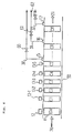
- Fig. 2 is a graph showing an operation state of the compressor of the embodiment of Fig. 1, wherein Fig. 2(a) shows an opening setting state of the IGV 11 and the five variable stator vanes C1, C2, C3, C4, C5 relative to the speed elevation and Fig. 2(b) shows an opening setting state of No. 5, No. 8, No. 11 bleed valves 1, 2, 3 relative to the speed elevation. It is to be noted that No. 5, No. 8 and No. 11 bleed valves correspond to the bleed valves 1, 2 and 3, respectively.
- the opening setting (angle) of the IGV 11 and the variable stator vanes C1 to C5 is so made that 50° for the IGV, 40° for C1, 24° for C2, 20° for C3 and 16° each for C4 and C5. Then, during the time of the speed from 80% to 95%, the respective stator vanes C1 to C5 are further opened gradually in proportion to the speed elevation so as to be fully opened at the speed of 95%, while the IGV 11 is maintained to the opening of 50° until the speed of 86% and is then further opened gradually so as to be set to 41.5° at the speed of 95%, which is maintained thereafter.
- each of No. 5, No. 8, No. 11 bleed valves 1, 2, 3 is set to any one, selected differently from each other, of opening set values, wherein said opening set values are five values, as illustrated for example, selected between 100% (fully opened) and 0% (fully closed) for each of the bleed valves, and in this state, the operation is started. Then, the bleed valves 1, 2, 3 are fully opened on a half way of the speed elevation, that is, in the example of Fig. 2(b), No. 5 bleed valve 1 is fully opened when the speed is elevated to 52% and No. 8 and No. 11 bleed valves 2, 3 are fully opened both at the speed of 51%, and the speed continues to be elevated.
- the compressor 40 is so controlled by the control unit 4 that the IGV 11 is set to a predetermined opening which is slightly changed on the way, the variable stator vanes C1 to C5 are set to a predetermined opening until the speed of 80% and are then further opened gradually in proportion to the speed elevation from 80% to 95% to be fully opened at the speed of 95%.
- the compressor 40 is also controlled to be started by the control unit 4 such that No. 5 bleed valve 1, No. 8 bleed valve 2, No. 11 bleed valve 3 are throttled to a predetermined opening until the half way of the speed elevation and are then fully opened until the speed exceeds 90%, when they are fully closed.
- the three bleed valves 1, 2, 3 are set to the openings which are different from each other, for example, to a larger opening for the front or middle stage bleed valves and a smaller or zero opening for the rear stage bleed valves, thereby the air discharged in vain can be reduced and also an occurrence of the fluid unstableness phenomenon can be suppressed by such controlled operation.
- the compressor is operated to be started with the bleed valves being throttled and then being fully opened on the way of the speed elevation, hence the power of the starter motor at the time of the starting can be a smaller one as compared with the prior art case.
- the bleed valves 1, 2, 3 are so controlled as mentioned above by the control unit 4, thereby an occurrence of the fluid unstableness phenomenon can be suppressed as compared with the prior art case where the bleed valves are either fully opened or fully closed only.
Landscapes
- Engineering & Computer Science (AREA)
- Mechanical Engineering (AREA)
- General Engineering & Computer Science (AREA)
- Chemical & Material Sciences (AREA)
- Combustion & Propulsion (AREA)
- Life Sciences & Earth Sciences (AREA)
- Sustainable Development (AREA)
- Control Of Positive-Displacement Air Blowers (AREA)
- Control Of Turbines (AREA)
- Structures Of Non-Positive Displacement Pumps (AREA)
Abstract
Description
Claims (10)
- A gas turbine starting method comprising a step of setting an inlet guide vane (11) and a variable stator vane (C1 to C5) of a gas turbine compressor (40) to a predetermined opening during a starting time from a start initiation to a rated speed, characterized in that a plurality of bleed valves (1, 2, 3) of said compressor (40) are made variable of their openings and are controlled to a predetermined opening during said starting time.
- A gas turbine starting method as claimed in Claim 2, characterized in that an opening setting of said plurality of bleed valves (1, 2, 3) is such that said plurality of bleed valves (1, 2, 3) are throttled to a predetermined opening for a time from the start initiation to a half way of a speed elevation, are fully opened at said half way of the speed elevation and are fully closed immediately before the rated speed.
- A gas turbine starting method as claimed in Claim 2, characterized in that said opening setting of the plurality of bleed valves (1, 2, 3) for the time from the start initiation to the half way of the speed elevation is such that said plurality of bleed valves (1, 2, 3) are set to openings which are different from each other.
- A gas turbine starting method as claimed in Claim 3, characterized in that said opening setting of the plurality of bleed valves (1,2,3) for the time from the start initiation to the half way of the speed elevation is such that at least one of said plurality of bleed valves (1, 2, 3) is fully closed.
- A gas turbine starting method as claimed in any one of Claims 2 to 4, characterized in that a speed when said plurality of bleed valves (1, 2, 3) are fully opened is that which exceeds about 50% of the rated speed and at least one of said plurality of bleed valves (1, 2, 3) is different in said speed from others of said plurality of bleed valves (1, 2, 3).
- A gas turbine starting method as claimed in any one of Claims 2 to 4, characterized in that a speed when said plurality of bleed valves (1, 2, 3) are fully closed is that which exceeds about 90% of the rated speed.
- A gas turbine starting method as claimed in Claim 5, characterized in that a speed when said plurality of bleed valves (1, 2, 3) are fully closed is that which exceeds about 90% of the rated speed.
- A gas turbine starting method as claimed in any one of Claims 1 to 4, or 7, characterized in that said plurality of bleed valves (1, 2, 3) are arranged such that each one of them (1, 2, 3) is connected to a portion immediately after a fifth stage stator vane (C5), an eighth stage stator vane (C8) and an eleventh stage stator vane (C11), respectively, of said compressor (40).
- A gas turbine starting method as claimed in Claim 5, characterized in that said plurality of bleed valves (1, 2, 3) are arranged such that each one of them (1, 2, 3) is connected to a portion immediately after a fifth stage stator vane (C5), an eighth stage stator vane (C8) and an eleventh stage stator vane (C11), respectively, of said compressor (40).
- A gas turbine starting method as claimed in Claim 6, characterized in that said plurality of bleed valves (1, 2, 3) are arranged such that each one of them (1, 2, 3) is connected to a portion immediately after a fifth stage stator vane (C5), an eighth stage stator vane (C8) and an eleventh stage stator vane (C11), respectively, of said compressor (40).
Applications Claiming Priority (2)
| Application Number | Priority Date | Filing Date | Title |
|---|---|---|---|
| JP9637299 | 1999-04-02 | ||
| JP09637299A JP4115037B2 (en) | 1999-04-02 | 1999-04-02 | Gas turbine startup method |
Publications (3)
| Publication Number | Publication Date |
|---|---|
| EP1041290A2 true EP1041290A2 (en) | 2000-10-04 |
| EP1041290A3 EP1041290A3 (en) | 2003-01-08 |
| EP1041290B1 EP1041290B1 (en) | 2005-06-01 |
Family
ID=14163149
Family Applications (1)
| Application Number | Title | Priority Date | Filing Date |
|---|---|---|---|
| EP00105406A Expired - Lifetime EP1041290B1 (en) | 1999-04-02 | 2000-03-14 | Gas turbine starting method |
Country Status (5)
| Country | Link |
|---|---|
| US (1) | US6328526B1 (en) |
| EP (1) | EP1041290B1 (en) |
| JP (1) | JP4115037B2 (en) |
| CA (1) | CA2300606C (en) |
| DE (1) | DE60020441T2 (en) |
Cited By (4)
| Publication number | Priority date | Publication date | Assignee | Title |
|---|---|---|---|---|
| EP2128449A1 (en) * | 2008-05-28 | 2009-12-02 | Compressor Controls Corporation | Enhanced turbocompressor startup |
| EP2568141A1 (en) * | 2011-09-09 | 2013-03-13 | Siemens Aktiengesellschaft | Method for accelerating the rotor of a stationary gas turbine to nominal speed |
| WO2018234021A1 (en) * | 2017-06-19 | 2018-12-27 | Siemens Aktiengesellschaft | METHOD FOR STARTING AND STOPPING GAS TURBINE IN GAS AND STEAM TURBINE INSTALLATION |
| EP3736424A1 (en) * | 2019-05-02 | 2020-11-11 | Raytheon Technologies Corporation | Assisted engine start bleed system |
Families Citing this family (24)
| Publication number | Priority date | Publication date | Assignee | Title |
|---|---|---|---|---|
| US7131275B2 (en) * | 2002-12-06 | 2006-11-07 | Hamilton Sundstrand | Gas turbine engine system having an electric starter motor with integral clutch |
| US7096667B2 (en) * | 2004-01-09 | 2006-08-29 | Siemens Power Generation, Inc. | Control of gas turbine for catalyst activation |
| US20050235649A1 (en) * | 2004-01-09 | 2005-10-27 | Siemens Westinghouse Power Corporation | Method for operating a gas turbine |
| US7269953B2 (en) * | 2004-08-27 | 2007-09-18 | Siemens Power Generation, Inc. | Method of controlling a power generation system |
| JP5119676B2 (en) * | 2007-02-14 | 2013-01-16 | 株式会社日立製作所 | High humidity gas turbine |
| US7972105B2 (en) * | 2007-05-10 | 2011-07-05 | General Electric Company | Turbine anti-rotating stall schedule |
| ITMI20072403A1 (en) * | 2007-12-20 | 2009-06-21 | Nuovo Pignone Spa | METHOD FOR CHECKING LOAD VARIATIONS IN A GAS TURBINE |
| US8220275B2 (en) * | 2009-01-14 | 2012-07-17 | General Electric Company | Inlet bleed heat system thermal lag mitigation using compressor interstage bleeds |
| US8955334B2 (en) | 2010-07-22 | 2015-02-17 | General Electric Company | Systems and methods for controlling the startup of a gas turbine |
| US20120134783A1 (en) * | 2010-11-30 | 2012-05-31 | General Electric Company | System and method for operating a compressor |
| US20130074512A1 (en) * | 2011-09-23 | 2013-03-28 | Steven William Tillery | Inlet fluid flow and impingement angle control |
| DE102011088820A1 (en) * | 2011-12-16 | 2013-06-20 | Siemens Aktiengesellschaft | Turbomachine and method for operating such |
| US9228501B2 (en) | 2012-12-14 | 2016-01-05 | Solar Turbines Incorporated | Bleed valve override schedule on off-load transients |
| EP2959236B1 (en) * | 2013-02-20 | 2018-10-31 | Carrier Corporation | Inlet guide vane mechanism |
| US9611752B2 (en) | 2013-03-15 | 2017-04-04 | General Electric Company | Compressor start bleed system for a turbine system and method of controlling a compressor start bleed system |
| US9989030B2 (en) | 2015-03-24 | 2018-06-05 | Ingersoll-Rand Company | Fluid powered starter with a variable turbine stator |
| JP6738601B2 (en) * | 2015-11-04 | 2020-08-12 | 三菱日立パワーシステムズ株式会社 | Gas turbine starting method and apparatus |
| US10408217B2 (en) | 2016-03-15 | 2019-09-10 | General Electric Company | Controlling a compressor of a gas turbine engine |
| US10724443B2 (en) | 2016-05-24 | 2020-07-28 | General Electric Company | Turbine engine and method of operating |
| JP6639338B2 (en) * | 2016-07-11 | 2020-02-05 | 三菱日立パワーシステムズ株式会社 | Gas turbine and method of operating gas turbine |
| US10801361B2 (en) | 2016-09-09 | 2020-10-13 | General Electric Company | System and method for HPT disk over speed prevention |
| KR102768138B1 (en) | 2020-09-08 | 2025-02-13 | 미츠비시 파워 가부시키가이샤 | Clearance control system for gas turbines |
| CN115898652A (en) * | 2022-11-18 | 2023-04-04 | 华能上海燃机发电有限责任公司 | A method and system for controlling the start-up phase of a gas turbine |
| JP2025162630A (en) | 2024-04-16 | 2025-10-28 | 三菱重工業株式会社 | Gas turbine startup method |
Family Cites Families (17)
| Publication number | Priority date | Publication date | Assignee | Title |
|---|---|---|---|---|
| US2305311A (en) * | 1937-07-07 | 1942-12-15 | Jendrassik George | Gas turbine plant equipped with regulating apparatus |
| GB701576A (en) * | 1950-06-28 | 1953-12-30 | Rolls Royce | Improvements in or relating to compressors |
| GB911535A (en) * | 1959-08-24 | 1962-11-28 | Rolls Royce | Compressors for gas turbine engines |
| CH394471A (en) * | 1962-04-03 | 1965-06-30 | Bbc Brown Boveri & Cie | Method and device for preventing pumps in axial compressors |
| US3677000A (en) * | 1970-04-27 | 1972-07-18 | Faulkner C Thomson | System for the detection and control of compressor stall |
| US3996964A (en) * | 1972-09-15 | 1976-12-14 | The Bendix Corporation | Control apparatus particularly for a plurality of compressor bleed valves of a gas turbine engine |
| US3979903A (en) * | 1974-08-01 | 1976-09-14 | General Electric Company | Gas turbine engine with booster stage |
| US4428194A (en) * | 1981-02-19 | 1984-01-31 | The Garrett Corporation | Compressor bleed air control apparatus and methods |
| US4403912A (en) * | 1981-03-23 | 1983-09-13 | Avco Corporation | Integrated multiplane actuator system for compressor variable vanes and air bleed valve |
| JPH0621572B2 (en) * | 1984-12-14 | 1994-03-23 | 株式会社日立製作所 | Gas turbine plant starting method and gas turbine plant |
| US5117625A (en) * | 1988-05-23 | 1992-06-02 | Sundstrand Corporation | Integrated bleed load compressor and turbine control system |
| JPH03504408A (en) * | 1989-02-27 | 1991-09-26 | ユナイテッド・テクノロジーズ・コーポレイション | Gas turbine engine control device |
| US5281087A (en) * | 1992-06-10 | 1994-01-25 | General Electric Company | Industrial gas turbine engine with dual panel variable vane assembly |
| JPH06147189A (en) * | 1992-11-11 | 1994-05-27 | Hitachi Ltd | Propagating stall preventing device of compressor |
| US5375412A (en) * | 1993-04-26 | 1994-12-27 | United Technologies Corporation | Rotating stall recovery |
| US6059522A (en) * | 1996-04-17 | 2000-05-09 | United Technologies Corporation | Compressor stall diagnostics and avoidance |
| US6164902A (en) * | 1998-12-11 | 2000-12-26 | United Technologies Corporation | Controlling stall margin in a gas turbine engine during acceleration |
-
1999
- 1999-04-02 JP JP09637299A patent/JP4115037B2/en not_active Expired - Lifetime
-
2000
- 2000-03-14 EP EP00105406A patent/EP1041290B1/en not_active Expired - Lifetime
- 2000-03-14 DE DE60020441T patent/DE60020441T2/en not_active Expired - Lifetime
- 2000-03-14 CA CA002300606A patent/CA2300606C/en not_active Expired - Lifetime
- 2000-03-17 US US09/531,148 patent/US6328526B1/en not_active Expired - Lifetime
Non-Patent Citations (1)
| Title |
|---|
| None |
Cited By (8)
| Publication number | Priority date | Publication date | Assignee | Title |
|---|---|---|---|---|
| US9879688B2 (en) | 2008-03-13 | 2018-01-30 | Compressor Controls Corporation | Enhanced turbocompressor startup |
| US20180149163A1 (en) * | 2008-03-13 | 2018-05-31 | Compressor Controls Corporation | Enhanced turbocompressor starup |
| US10935036B2 (en) * | 2008-03-13 | 2021-03-02 | Compressor Controls Corporation | Enhanced turbocompressor startup |
| EP2128449A1 (en) * | 2008-05-28 | 2009-12-02 | Compressor Controls Corporation | Enhanced turbocompressor startup |
| EP2568141A1 (en) * | 2011-09-09 | 2013-03-13 | Siemens Aktiengesellschaft | Method for accelerating the rotor of a stationary gas turbine to nominal speed |
| WO2018234021A1 (en) * | 2017-06-19 | 2018-12-27 | Siemens Aktiengesellschaft | METHOD FOR STARTING AND STOPPING GAS TURBINE IN GAS AND STEAM TURBINE INSTALLATION |
| EP3736424A1 (en) * | 2019-05-02 | 2020-11-11 | Raytheon Technologies Corporation | Assisted engine start bleed system |
| US12071903B2 (en) | 2019-05-02 | 2024-08-27 | Rtx Corporation | Assisted engine start bleed system |
Also Published As
| Publication number | Publication date |
|---|---|
| US6328526B1 (en) | 2001-12-11 |
| EP1041290B1 (en) | 2005-06-01 |
| DE60020441T2 (en) | 2006-05-04 |
| JP4115037B2 (en) | 2008-07-09 |
| DE60020441D1 (en) | 2005-07-07 |
| CA2300606C (en) | 2004-09-07 |
| EP1041290A3 (en) | 2003-01-08 |
| JP2000291449A (en) | 2000-10-17 |
| CA2300606A1 (en) | 2000-10-02 |
Similar Documents
| Publication | Publication Date | Title |
|---|---|---|
| CA2300606C (en) | Gas turbine starting method | |
| JP3115846B2 (en) | Centrifugal compressor | |
| JP4897993B2 (en) | Turbine sidewall cavity pressure modulation system and method | |
| US5855117A (en) | Exhaust gas turbocharger for an internal combustion engine | |
| EP1252424B1 (en) | Method of operating a variable cycle gas turbine engine | |
| JP5306638B2 (en) | Turbine engine with flow control fan and method of operation | |
| EP3133249A1 (en) | Gas turbine engine having an air bleed system | |
| EP3133261A1 (en) | Compressor bleed auxiliary turbine | |
| EP3133246A1 (en) | Airflow injection nozzle for a gas turbine engine | |
| EP1825177B1 (en) | Inflatable bleed valve for turbine engine and method of controlling bleed air | |
| EP1999354B1 (en) | Method of operating a gas turbine power plant | |
| US20180171877A1 (en) | Power Generation System and Method for Operating Same | |
| KR101299801B1 (en) | Method for controlling a turbocompressor | |
| US20090196732A1 (en) | Turbomachine, in Particular a Gas Turbine | |
| US9664118B2 (en) | Method and system for controlling compressor forward leakage | |
| EP3109435B1 (en) | Intercooled cooling air with heat exchanger packaging | |
| JP3959172B2 (en) | Steam turbine control method | |
| US11519339B2 (en) | System and methods for controlling surge margin in the compressor section of a gas turbine engine | |
| RU2165547C2 (en) | Aircraft engine multi-stage axial-flow compressor | |
| EP4166770B1 (en) | Gas turbine engine with compressor bleed system for combustor start assist |
Legal Events
| Date | Code | Title | Description |
|---|---|---|---|
| PUAI | Public reference made under article 153(3) epc to a published international application that has entered the european phase |
Free format text: ORIGINAL CODE: 0009012 |
|
| 17P | Request for examination filed |
Effective date: 20000411 |
|
| AK | Designated contracting states |
Kind code of ref document: A2 Designated state(s): AT BE CH CY DE DK ES FI FR GB GR IE IT LI LU MC NL PT SE |
|
| AX | Request for extension of the european patent |
Free format text: AL;LT;LV;MK;RO;SI |
|
| PUAL | Search report despatched |
Free format text: ORIGINAL CODE: 0009013 |
|
| AK | Designated contracting states |
Kind code of ref document: A3 Designated state(s): AT BE CH CY DE DK ES FI FR GB GR IE IT LI LU MC NL PT SE |
|
| AX | Request for extension of the european patent |
Free format text: AL;LT;LV;MK;RO;SI |
|
| RIC1 | Information provided on ipc code assigned before grant |
Free format text: 7F 04D 27/02 A, 7F 02C 7/26 B, 7F 02C 9/18 B |
|
| AKX | Designation fees paid |
Designated state(s): CH DE FR GB IT LI |
|
| 17Q | First examination report despatched |
Effective date: 20040408 |
|
| GRAP | Despatch of communication of intention to grant a patent |
Free format text: ORIGINAL CODE: EPIDOSNIGR1 |
|
| GRAS | Grant fee paid |
Free format text: ORIGINAL CODE: EPIDOSNIGR3 |
|
| GRAA | (expected) grant |
Free format text: ORIGINAL CODE: 0009210 |
|
| AK | Designated contracting states |
Kind code of ref document: B1 Designated state(s): CH DE FR GB IT LI |
|
| PG25 | Lapsed in a contracting state [announced via postgrant information from national office to epo] |
Ref country code: IT Free format text: LAPSE BECAUSE OF FAILURE TO SUBMIT A TRANSLATION OF THE DESCRIPTION OR TO PAY THE FEE WITHIN THE PRESCRIBED TIME-LIMIT;WARNING: LAPSES OF ITALIAN PATENTS WITH EFFECTIVE DATE BEFORE 2007 MAY HAVE OCCURRED AT ANY TIME BEFORE 2007. THE CORRECT EFFECTIVE DATE MAY BE DIFFERENT FROM THE ONE RECORDED. Effective date: 20050601 Ref country code: LI Free format text: LAPSE BECAUSE OF FAILURE TO SUBMIT A TRANSLATION OF THE DESCRIPTION OR TO PAY THE FEE WITHIN THE PRESCRIBED TIME-LIMIT Effective date: 20050601 Ref country code: CH Free format text: LAPSE BECAUSE OF FAILURE TO SUBMIT A TRANSLATION OF THE DESCRIPTION OR TO PAY THE FEE WITHIN THE PRESCRIBED TIME-LIMIT Effective date: 20050601 |
|
| REG | Reference to a national code |
Ref country code: GB Ref legal event code: FG4D |
|
| REG | Reference to a national code |
Ref country code: CH Ref legal event code: EP |
|
| REG | Reference to a national code |
Ref country code: IE Ref legal event code: FG4D |
|
| REF | Corresponds to: |
Ref document number: 60020441 Country of ref document: DE Date of ref document: 20050707 Kind code of ref document: P |
|
| REG | Reference to a national code |
Ref country code: CH Ref legal event code: PL |
|
| PG25 | Lapsed in a contracting state [announced via postgrant information from national office to epo] |
Ref country code: GB Free format text: LAPSE BECAUSE OF NON-PAYMENT OF DUE FEES Effective date: 20060314 |
|
| PLBE | No opposition filed within time limit |
Free format text: ORIGINAL CODE: 0009261 |
|
| STAA | Information on the status of an ep patent application or granted ep patent |
Free format text: STATUS: NO OPPOSITION FILED WITHIN TIME LIMIT |
|
| 26N | No opposition filed |
Effective date: 20060302 |
|
| EN | Fr: translation not filed | ||
| GBPC | Gb: european patent ceased through non-payment of renewal fee |
Effective date: 20060314 |
|
| PG25 | Lapsed in a contracting state [announced via postgrant information from national office to epo] |
Ref country code: FR Free format text: LAPSE BECAUSE OF FAILURE TO SUBMIT A TRANSLATION OF THE DESCRIPTION OR TO PAY THE FEE WITHIN THE PRESCRIBED TIME-LIMIT Effective date: 20050601 |
|
| REG | Reference to a national code |
Ref country code: DE Ref legal event code: R082 Ref document number: 60020441 Country of ref document: DE Representative=s name: PATENTANWAELTE HENKEL, BREUER & PARTNER, DE Ref country code: DE Ref legal event code: R081 Ref document number: 60020441 Country of ref document: DE Owner name: MITSUBISHI HITACHI POWER SYSTEMS, LTD., YOKOHA, JP Free format text: FORMER OWNER: MITSUBISHI HEAVY INDUSTRIES, LTD., TOKYO, JP |
|
| PGFP | Annual fee paid to national office [announced via postgrant information from national office to epo] |
Ref country code: DE Payment date: 20190226 Year of fee payment: 20 |
|
| REG | Reference to a national code |
Ref country code: DE Ref legal event code: R071 Ref document number: 60020441 Country of ref document: DE |