EP3736383A2 - Braking control device and braking control method of construction machine - Google Patents
Braking control device and braking control method of construction machine Download PDFInfo
- Publication number
- EP3736383A2 EP3736383A2 EP19747081.8A EP19747081A EP3736383A2 EP 3736383 A2 EP3736383 A2 EP 3736383A2 EP 19747081 A EP19747081 A EP 19747081A EP 3736383 A2 EP3736383 A2 EP 3736383A2
- Authority
- EP
- European Patent Office
- Prior art keywords
- brake
- construction machinery
- brake control
- signal
- conversion ratio
- Prior art date
- Legal status (The legal status is an assumption and is not a legal conclusion. Google has not performed a legal analysis and makes no representation as to the accuracy of the status listed.)
- Granted
Links
Images

Classifications
-
- E—FIXED CONSTRUCTIONS
- E02—HYDRAULIC ENGINEERING; FOUNDATIONS; SOIL SHIFTING
- E02F—DREDGING; SOIL-SHIFTING
- E02F9/00—Component parts of dredgers or soil-shifting machines, not restricted to one of the kinds covered by groups E02F3/00 - E02F7/00
- E02F9/20—Drives; Control devices
- E02F9/2058—Electric or electro-mechanical or mechanical control devices of vehicle sub-units
- E02F9/2083—Control of vehicle braking systems
-
- E—FIXED CONSTRUCTIONS
- E02—HYDRAULIC ENGINEERING; FOUNDATIONS; SOIL SHIFTING
- E02F—DREDGING; SOIL-SHIFTING
- E02F9/00—Component parts of dredgers or soil-shifting machines, not restricted to one of the kinds covered by groups E02F3/00 - E02F7/00
- E02F9/20—Drives; Control devices
- E02F9/22—Hydraulic or pneumatic drives
- E02F9/2221—Control of flow rate; Load sensing arrangements
-
- E—FIXED CONSTRUCTIONS
- E02—HYDRAULIC ENGINEERING; FOUNDATIONS; SOIL SHIFTING
- E02F—DREDGING; SOIL-SHIFTING
- E02F9/00—Component parts of dredgers or soil-shifting machines, not restricted to one of the kinds covered by groups E02F3/00 - E02F7/00
- E02F9/20—Drives; Control devices
- E02F9/22—Hydraulic or pneumatic drives
- E02F9/226—Safety arrangements, e.g. hydraulic driven fans, preventing cavitation, leakage, overheating
-
- B—PERFORMING OPERATIONS; TRANSPORTING
- B60—VEHICLES IN GENERAL
- B60T—VEHICLE BRAKE CONTROL SYSTEMS OR PARTS THEREOF; BRAKE CONTROL SYSTEMS OR PARTS THEREOF, IN GENERAL; ARRANGEMENT OF BRAKING ELEMENTS ON VEHICLES IN GENERAL; PORTABLE DEVICES FOR PREVENTING UNWANTED MOVEMENT OF VEHICLES; VEHICLE MODIFICATIONS TO FACILITATE COOLING OF BRAKES
- B60T13/00—Transmitting braking action from initiating means to ultimate brake actuator with power assistance or drive; Brake systems incorporating such transmitting means, e.g. air-pressure brake systems
- B60T13/10—Transmitting braking action from initiating means to ultimate brake actuator with power assistance or drive; Brake systems incorporating such transmitting means, e.g. air-pressure brake systems with fluid assistance, drive, or release
- B60T13/12—Transmitting braking action from initiating means to ultimate brake actuator with power assistance or drive; Brake systems incorporating such transmitting means, e.g. air-pressure brake systems with fluid assistance, drive, or release the fluid being liquid
- B60T13/16—Transmitting braking action from initiating means to ultimate brake actuator with power assistance or drive; Brake systems incorporating such transmitting means, e.g. air-pressure brake systems with fluid assistance, drive, or release the fluid being liquid using pumps directly, i.e. without interposition of accumulators or reservoirs
- B60T13/18—Transmitting braking action from initiating means to ultimate brake actuator with power assistance or drive; Brake systems incorporating such transmitting means, e.g. air-pressure brake systems with fluid assistance, drive, or release the fluid being liquid using pumps directly, i.e. without interposition of accumulators or reservoirs with control of pump output delivery, e.g. by distributor valves
-
- B—PERFORMING OPERATIONS; TRANSPORTING
- B60—VEHICLES IN GENERAL
- B60T—VEHICLE BRAKE CONTROL SYSTEMS OR PARTS THEREOF; BRAKE CONTROL SYSTEMS OR PARTS THEREOF, IN GENERAL; ARRANGEMENT OF BRAKING ELEMENTS ON VEHICLES IN GENERAL; PORTABLE DEVICES FOR PREVENTING UNWANTED MOVEMENT OF VEHICLES; VEHICLE MODIFICATIONS TO FACILITATE COOLING OF BRAKES
- B60T7/00—Brake-action initiating means
- B60T7/02—Brake-action initiating means for personal initiation
- B60T7/04—Brake-action initiating means for personal initiation foot actuated
- B60T7/042—Brake-action initiating means for personal initiation foot actuated by electrical means, e.g. using travel or force sensors
-
- B—PERFORMING OPERATIONS; TRANSPORTING
- B60—VEHICLES IN GENERAL
- B60T—VEHICLE BRAKE CONTROL SYSTEMS OR PARTS THEREOF; BRAKE CONTROL SYSTEMS OR PARTS THEREOF, IN GENERAL; ARRANGEMENT OF BRAKING ELEMENTS ON VEHICLES IN GENERAL; PORTABLE DEVICES FOR PREVENTING UNWANTED MOVEMENT OF VEHICLES; VEHICLE MODIFICATIONS TO FACILITATE COOLING OF BRAKES
- B60T8/00—Arrangements for adjusting wheel-braking force to meet varying vehicular or ground-surface conditions, e.g. limiting or varying distribution of braking force
- B60T8/17—Using electrical or electronic regulation means to control braking
-
- B—PERFORMING OPERATIONS; TRANSPORTING
- B60—VEHICLES IN GENERAL
- B60T—VEHICLE BRAKE CONTROL SYSTEMS OR PARTS THEREOF; BRAKE CONTROL SYSTEMS OR PARTS THEREOF, IN GENERAL; ARRANGEMENT OF BRAKING ELEMENTS ON VEHICLES IN GENERAL; PORTABLE DEVICES FOR PREVENTING UNWANTED MOVEMENT OF VEHICLES; VEHICLE MODIFICATIONS TO FACILITATE COOLING OF BRAKES
- B60T8/00—Arrangements for adjusting wheel-braking force to meet varying vehicular or ground-surface conditions, e.g. limiting or varying distribution of braking force
- B60T8/17—Using electrical or electronic regulation means to control braking
- B60T8/171—Detecting parameters used in the regulation; Measuring values used in the regulation
-
- B—PERFORMING OPERATIONS; TRANSPORTING
- B60—VEHICLES IN GENERAL
- B60T—VEHICLE BRAKE CONTROL SYSTEMS OR PARTS THEREOF; BRAKE CONTROL SYSTEMS OR PARTS THEREOF, IN GENERAL; ARRANGEMENT OF BRAKING ELEMENTS ON VEHICLES IN GENERAL; PORTABLE DEVICES FOR PREVENTING UNWANTED MOVEMENT OF VEHICLES; VEHICLE MODIFICATIONS TO FACILITATE COOLING OF BRAKES
- B60T8/00—Arrangements for adjusting wheel-braking force to meet varying vehicular or ground-surface conditions, e.g. limiting or varying distribution of braking force
- B60T8/17—Using electrical or electronic regulation means to control braking
- B60T8/172—Determining control parameters used in the regulation, e.g. by calculations involving measured or detected parameters
-
- B—PERFORMING OPERATIONS; TRANSPORTING
- B60—VEHICLES IN GENERAL
- B60T—VEHICLE BRAKE CONTROL SYSTEMS OR PARTS THEREOF; BRAKE CONTROL SYSTEMS OR PARTS THEREOF, IN GENERAL; ARRANGEMENT OF BRAKING ELEMENTS ON VEHICLES IN GENERAL; PORTABLE DEVICES FOR PREVENTING UNWANTED MOVEMENT OF VEHICLES; VEHICLE MODIFICATIONS TO FACILITATE COOLING OF BRAKES
- B60T8/00—Arrangements for adjusting wheel-braking force to meet varying vehicular or ground-surface conditions, e.g. limiting or varying distribution of braking force
- B60T8/17—Using electrical or electronic regulation means to control braking
- B60T8/176—Brake regulation specially adapted to prevent excessive wheel slip during vehicle deceleration, e.g. ABS
-
- B—PERFORMING OPERATIONS; TRANSPORTING
- B60—VEHICLES IN GENERAL
- B60T—VEHICLE BRAKE CONTROL SYSTEMS OR PARTS THEREOF; BRAKE CONTROL SYSTEMS OR PARTS THEREOF, IN GENERAL; ARRANGEMENT OF BRAKING ELEMENTS ON VEHICLES IN GENERAL; PORTABLE DEVICES FOR PREVENTING UNWANTED MOVEMENT OF VEHICLES; VEHICLE MODIFICATIONS TO FACILITATE COOLING OF BRAKES
- B60T8/00—Arrangements for adjusting wheel-braking force to meet varying vehicular or ground-surface conditions, e.g. limiting or varying distribution of braking force
- B60T8/18—Arrangements for adjusting wheel-braking force to meet varying vehicular or ground-surface conditions, e.g. limiting or varying distribution of braking force responsive to vehicle weight or load, e.g. load distribution
-
- B—PERFORMING OPERATIONS; TRANSPORTING
- B60—VEHICLES IN GENERAL
- B60T—VEHICLE BRAKE CONTROL SYSTEMS OR PARTS THEREOF; BRAKE CONTROL SYSTEMS OR PARTS THEREOF, IN GENERAL; ARRANGEMENT OF BRAKING ELEMENTS ON VEHICLES IN GENERAL; PORTABLE DEVICES FOR PREVENTING UNWANTED MOVEMENT OF VEHICLES; VEHICLE MODIFICATIONS TO FACILITATE COOLING OF BRAKES
- B60T8/00—Arrangements for adjusting wheel-braking force to meet varying vehicular or ground-surface conditions, e.g. limiting or varying distribution of braking force
- B60T8/24—Arrangements for adjusting wheel-braking force to meet varying vehicular or ground-surface conditions, e.g. limiting or varying distribution of braking force responsive to vehicle inclination or change of direction, e.g. negotiating bends
- B60T8/245—Longitudinal vehicle inclination
-
- B—PERFORMING OPERATIONS; TRANSPORTING
- B60—VEHICLES IN GENERAL
- B60T—VEHICLE BRAKE CONTROL SYSTEMS OR PARTS THEREOF; BRAKE CONTROL SYSTEMS OR PARTS THEREOF, IN GENERAL; ARRANGEMENT OF BRAKING ELEMENTS ON VEHICLES IN GENERAL; PORTABLE DEVICES FOR PREVENTING UNWANTED MOVEMENT OF VEHICLES; VEHICLE MODIFICATIONS TO FACILITATE COOLING OF BRAKES
- B60T8/00—Arrangements for adjusting wheel-braking force to meet varying vehicular or ground-surface conditions, e.g. limiting or varying distribution of braking force
- B60T8/32—Arrangements for adjusting wheel-braking force to meet varying vehicular or ground-surface conditions, e.g. limiting or varying distribution of braking force responsive to a speed condition, e.g. acceleration or deceleration
- B60T8/321—Arrangements for adjusting wheel-braking force to meet varying vehicular or ground-surface conditions, e.g. limiting or varying distribution of braking force responsive to a speed condition, e.g. acceleration or deceleration deceleration
-
- B—PERFORMING OPERATIONS; TRANSPORTING
- B60—VEHICLES IN GENERAL
- B60T—VEHICLE BRAKE CONTROL SYSTEMS OR PARTS THEREOF; BRAKE CONTROL SYSTEMS OR PARTS THEREOF, IN GENERAL; ARRANGEMENT OF BRAKING ELEMENTS ON VEHICLES IN GENERAL; PORTABLE DEVICES FOR PREVENTING UNWANTED MOVEMENT OF VEHICLES; VEHICLE MODIFICATIONS TO FACILITATE COOLING OF BRAKES
- B60T8/00—Arrangements for adjusting wheel-braking force to meet varying vehicular or ground-surface conditions, e.g. limiting or varying distribution of braking force
- B60T8/32—Arrangements for adjusting wheel-braking force to meet varying vehicular or ground-surface conditions, e.g. limiting or varying distribution of braking force responsive to a speed condition, e.g. acceleration or deceleration
- B60T8/321—Arrangements for adjusting wheel-braking force to meet varying vehicular or ground-surface conditions, e.g. limiting or varying distribution of braking force responsive to a speed condition, e.g. acceleration or deceleration deceleration
- B60T8/3255—Systems in which the braking action is dependent on brake pedal data
- B60T8/326—Hydraulic systems
-
- B—PERFORMING OPERATIONS; TRANSPORTING
- B60—VEHICLES IN GENERAL
- B60T—VEHICLE BRAKE CONTROL SYSTEMS OR PARTS THEREOF; BRAKE CONTROL SYSTEMS OR PARTS THEREOF, IN GENERAL; ARRANGEMENT OF BRAKING ELEMENTS ON VEHICLES IN GENERAL; PORTABLE DEVICES FOR PREVENTING UNWANTED MOVEMENT OF VEHICLES; VEHICLE MODIFICATIONS TO FACILITATE COOLING OF BRAKES
- B60T8/00—Arrangements for adjusting wheel-braking force to meet varying vehicular or ground-surface conditions, e.g. limiting or varying distribution of braking force
- B60T8/32—Arrangements for adjusting wheel-braking force to meet varying vehicular or ground-surface conditions, e.g. limiting or varying distribution of braking force responsive to a speed condition, e.g. acceleration or deceleration
- B60T8/88—Arrangements for adjusting wheel-braking force to meet varying vehicular or ground-surface conditions, e.g. limiting or varying distribution of braking force responsive to a speed condition, e.g. acceleration or deceleration with failure responsive means, i.e. means for detecting and indicating faulty operation of the speed responsive control means
- B60T8/92—Arrangements for adjusting wheel-braking force to meet varying vehicular or ground-surface conditions, e.g. limiting or varying distribution of braking force responsive to a speed condition, e.g. acceleration or deceleration with failure responsive means, i.e. means for detecting and indicating faulty operation of the speed responsive control means automatically taking corrective action
-
- E—FIXED CONSTRUCTIONS
- E02—HYDRAULIC ENGINEERING; FOUNDATIONS; SOIL SHIFTING
- E02F—DREDGING; SOIL-SHIFTING
- E02F9/00—Component parts of dredgers or soil-shifting machines, not restricted to one of the kinds covered by groups E02F3/00 - E02F7/00
- E02F9/20—Drives; Control devices
- E02F9/2004—Control mechanisms, e.g. control levers
-
- E—FIXED CONSTRUCTIONS
- E02—HYDRAULIC ENGINEERING; FOUNDATIONS; SOIL SHIFTING
- E02F—DREDGING; SOIL-SHIFTING
- E02F9/00—Component parts of dredgers or soil-shifting machines, not restricted to one of the kinds covered by groups E02F3/00 - E02F7/00
- E02F9/20—Drives; Control devices
- E02F9/22—Hydraulic or pneumatic drives
- E02F9/2221—Control of flow rate; Load sensing arrangements
- E02F9/2225—Control of flow rate; Load sensing arrangements using pressure-compensating valves
- E02F9/2228—Control of flow rate; Load sensing arrangements using pressure-compensating valves including an electronic controller
-
- E—FIXED CONSTRUCTIONS
- E02—HYDRAULIC ENGINEERING; FOUNDATIONS; SOIL SHIFTING
- E02F—DREDGING; SOIL-SHIFTING
- E02F9/00—Component parts of dredgers or soil-shifting machines, not restricted to one of the kinds covered by groups E02F3/00 - E02F7/00
- E02F9/20—Drives; Control devices
- E02F9/22—Hydraulic or pneumatic drives
- E02F9/2253—Controlling the travelling speed of vehicles, e.g. adjusting travelling speed according to implement loads, control of hydrostatic transmission
-
- E—FIXED CONSTRUCTIONS
- E02—HYDRAULIC ENGINEERING; FOUNDATIONS; SOIL SHIFTING
- E02F—DREDGING; SOIL-SHIFTING
- E02F9/00—Component parts of dredgers or soil-shifting machines, not restricted to one of the kinds covered by groups E02F3/00 - E02F7/00
- E02F9/20—Drives; Control devices
- E02F9/22—Hydraulic or pneumatic drives
- E02F9/2264—Arrangements or adaptations of elements for hydraulic drives
- E02F9/2267—Valves or distributors
-
- B—PERFORMING OPERATIONS; TRANSPORTING
- B60—VEHICLES IN GENERAL
- B60T—VEHICLE BRAKE CONTROL SYSTEMS OR PARTS THEREOF; BRAKE CONTROL SYSTEMS OR PARTS THEREOF, IN GENERAL; ARRANGEMENT OF BRAKING ELEMENTS ON VEHICLES IN GENERAL; PORTABLE DEVICES FOR PREVENTING UNWANTED MOVEMENT OF VEHICLES; VEHICLE MODIFICATIONS TO FACILITATE COOLING OF BRAKES
- B60T2210/00—Detection or estimation of road or environment conditions; Detection or estimation of road shapes
- B60T2210/20—Road shapes
-
- B—PERFORMING OPERATIONS; TRANSPORTING
- B60—VEHICLES IN GENERAL
- B60T—VEHICLE BRAKE CONTROL SYSTEMS OR PARTS THEREOF; BRAKE CONTROL SYSTEMS OR PARTS THEREOF, IN GENERAL; ARRANGEMENT OF BRAKING ELEMENTS ON VEHICLES IN GENERAL; PORTABLE DEVICES FOR PREVENTING UNWANTED MOVEMENT OF VEHICLES; VEHICLE MODIFICATIONS TO FACILITATE COOLING OF BRAKES
- B60T2220/00—Monitoring, detecting driver behaviour; Signalling thereof; Counteracting thereof
- B60T2220/04—Pedal travel sensor, stroke sensor; Sensing brake request
-
- B—PERFORMING OPERATIONS; TRANSPORTING
- B60—VEHICLES IN GENERAL
- B60T—VEHICLE BRAKE CONTROL SYSTEMS OR PARTS THEREOF; BRAKE CONTROL SYSTEMS OR PARTS THEREOF, IN GENERAL; ARRANGEMENT OF BRAKING ELEMENTS ON VEHICLES IN GENERAL; PORTABLE DEVICES FOR PREVENTING UNWANTED MOVEMENT OF VEHICLES; VEHICLE MODIFICATIONS TO FACILITATE COOLING OF BRAKES
- B60T2250/00—Monitoring, detecting, estimating vehicle conditions
-
- B—PERFORMING OPERATIONS; TRANSPORTING
- B60—VEHICLES IN GENERAL
- B60T—VEHICLE BRAKE CONTROL SYSTEMS OR PARTS THEREOF; BRAKE CONTROL SYSTEMS OR PARTS THEREOF, IN GENERAL; ARRANGEMENT OF BRAKING ELEMENTS ON VEHICLES IN GENERAL; PORTABLE DEVICES FOR PREVENTING UNWANTED MOVEMENT OF VEHICLES; VEHICLE MODIFICATIONS TO FACILITATE COOLING OF BRAKES
- B60T2250/00—Monitoring, detecting, estimating vehicle conditions
- B60T2250/04—Vehicle reference speed; Vehicle body speed
-
- B—PERFORMING OPERATIONS; TRANSPORTING
- B60—VEHICLES IN GENERAL
- B60T—VEHICLE BRAKE CONTROL SYSTEMS OR PARTS THEREOF; BRAKE CONTROL SYSTEMS OR PARTS THEREOF, IN GENERAL; ARRANGEMENT OF BRAKING ELEMENTS ON VEHICLES IN GENERAL; PORTABLE DEVICES FOR PREVENTING UNWANTED MOVEMENT OF VEHICLES; VEHICLE MODIFICATIONS TO FACILITATE COOLING OF BRAKES
- B60T2270/00—Further aspects of brake control systems not otherwise provided for
- B60T2270/10—ABS control systems
-
- B—PERFORMING OPERATIONS; TRANSPORTING
- B60—VEHICLES IN GENERAL
- B60T—VEHICLE BRAKE CONTROL SYSTEMS OR PARTS THEREOF; BRAKE CONTROL SYSTEMS OR PARTS THEREOF, IN GENERAL; ARRANGEMENT OF BRAKING ELEMENTS ON VEHICLES IN GENERAL; PORTABLE DEVICES FOR PREVENTING UNWANTED MOVEMENT OF VEHICLES; VEHICLE MODIFICATIONS TO FACILITATE COOLING OF BRAKES
- B60T2270/00—Further aspects of brake control systems not otherwise provided for
- B60T2270/40—Failsafe aspects of brake control systems
- B60T2270/402—Back-up
-
- B—PERFORMING OPERATIONS; TRANSPORTING
- B60—VEHICLES IN GENERAL
- B60T—VEHICLE BRAKE CONTROL SYSTEMS OR PARTS THEREOF; BRAKE CONTROL SYSTEMS OR PARTS THEREOF, IN GENERAL; ARRANGEMENT OF BRAKING ELEMENTS ON VEHICLES IN GENERAL; PORTABLE DEVICES FOR PREVENTING UNWANTED MOVEMENT OF VEHICLES; VEHICLE MODIFICATIONS TO FACILITATE COOLING OF BRAKES
- B60T2270/00—Further aspects of brake control systems not otherwise provided for
- B60T2270/40—Failsafe aspects of brake control systems
- B60T2270/404—Brake-by-wire or X-by-wire failsafe
-
- B—PERFORMING OPERATIONS; TRANSPORTING
- B60—VEHICLES IN GENERAL
- B60T—VEHICLE BRAKE CONTROL SYSTEMS OR PARTS THEREOF; BRAKE CONTROL SYSTEMS OR PARTS THEREOF, IN GENERAL; ARRANGEMENT OF BRAKING ELEMENTS ON VEHICLES IN GENERAL; PORTABLE DEVICES FOR PREVENTING UNWANTED MOVEMENT OF VEHICLES; VEHICLE MODIFICATIONS TO FACILITATE COOLING OF BRAKES
- B60T2270/00—Further aspects of brake control systems not otherwise provided for
- B60T2270/82—Brake-by-Wire, EHB
-
- E—FIXED CONSTRUCTIONS
- E02—HYDRAULIC ENGINEERING; FOUNDATIONS; SOIL SHIFTING
- E02F—DREDGING; SOIL-SHIFTING
- E02F9/00—Component parts of dredgers or soil-shifting machines, not restricted to one of the kinds covered by groups E02F3/00 - E02F7/00
- E02F9/20—Drives; Control devices
- E02F9/2025—Particular purposes of control systems not otherwise provided for
- E02F9/205—Remotely operated machines, e.g. unmanned vehicles
Definitions
- the present invention relates to a brake control system for construction machinery and a brake control method for construction machinery. More particularly, the present invention relates to a brake control system and a brake control method for a wheel type of construction machinery.
- a driver may control a hydraulic brake valve using a brake pedal in a manual brake manner.
- the hydraulic brake valve supplies a brake oil to both a front brake device and a rear brake device, it may be difficult to precisely control independently the front and rear brake devices according to conditions of the construction machinery.
- An object of the present invention provides an electro hydraulic brake control system for construction machinery capable of controlling independently a front brake device and a rear brake device.
- Another object of the present invention provides a brake control method for construction machinery using the above brake control system.
- a brake control apparatus for construction machinery includes first and second brake lines through which a brake oil is supplied to a front brake device and a rear brake device of the construction machinery, first and second proportional flow control valves installed respectively in the first and second brake lines to control a flow rate of the brake oil in proportion to inputted first and second brake control signals, a sensing portion configured to detect work and travel information of the construction machinery, and a controller configured to output the first and second brake control signals in response to a brake manipulation signal of a driver, and configured to control independently the first and second proportional flow control valves based on the work and travel information of the construction machinery detected by the sensing portion.
- the controller may convert the brake manipulation signal at a first conversion ratio to generate and output the first brake control signal and may convert the brake manipulation signal at a second conversion ratio to generate and output the second brake control signal.
- the first conversion ratio and the second conversion ratio may be changed depending on a magnitude of the brake manipulation signal.
- the first and second conversion ratios may have a first magnitude when the brake manipulation signal is less than a predetermined value, and the first and second conversion ratios may have a second magnitude when the brake manipulation signal is the predetermined value or more.
- the first and second conversion ratios may be adjusted to change according to a vehicle speed of the construction machinery.
- the first conversion ratio may increase as the vehicle speed increases and the second conversion ratio may decrease as the vehicle speed increases.
- the first conversion ratio and the second conversion ratio may be identical to each other when the vehicle speed is less than a predetermined value.
- the first and second conversion ratios may be adjusted to change according to live load of a bucket of the construction machinery.
- the first and second conversion ratios may be adjusted to change according to a height of a bucket of the construction machinery.
- the controller when the controller receives the brake manipulation signal for a certain period of time, the controller may execute a slope slip prevention mode and output the first and second brake control signals to operate the front brake device and the rear brake device.
- the controller may include a first control signal generator configured to convert the brake manipulation signal at a first conversion ratio based on the work and travel information of the construction machinery detected by the sensing portion to generate the first brake control signal, and a second control signal generator configured to convert the brake manipulation signal at a second conversion ratio based on the work and travel information of the construction machinery detected by the sensing portion to generate the second brake control signal.
- the sensing portion may include at least one of a boom angle sensor, a boom cylinder pressure sensor, a vehicle speed sensor and an acceleration sensor.
- the brake control apparatus for construction machinery may further include a parking brake line through which the brake oil is supplied to a parking brake device of the construction machinery, and a proportional direction control valve installed in the parking brake line to supply or block the brake oil according to an inputted parking control signal.
- the controller may output the parking control signal in case of an emergency occurrence.
- the brake control apparatus for construction machinery may further include an electronic pedal device configured to output the brake manipulation signal as an electronic signal in proportion to an angle change of a brake pedal by the driver.
- a brake control apparatus for construction machinery includes a hydraulic pump configured to supply a brake oil, first and second brake lines connected to the hydraulic pump to supply the brake oil to a front brake device and a rear brake device of the construction machinery therethrough, first and second proportional flow control valves installed respectively in the first and second brake lines to control a flow rate of the brake oil in proportion to inputted first and second brake control signals, a sensing portion including a boom angle sensor, a bucket angle sensor and a vehicle speed sensor and configured to detect work and travel information of the construction machinery, an electronic pedal device configured to output a brake manipulation signal as an electronic signal in proportion to an angle change of a brake pedal by a driver, and a controller configured to output the first and second brake control signals in response to the brake manipulation signal of the electronic pedal device, and configured to control independently the first and second proportional flow control valves based on the work and travel information of the construction machinery detected by the boom angle sensor, the bucket angle sensor, the vehicle speed sensor and the electronic pedal device.
- a hydraulic system including first and second brake lines through which a brake oil is supplied to a front brake device and a rear brake device of the construction machinery and first and second proportional flow control valves installed respectively in the first and second brake lines to control a flow rate of the brake oil in proportion to inputted first and second brake control signals.
- Work and travel information of the construction machinery are detected.
- the first and second brake control signals are outputted based on the work and travel information of construction machinery in response to a brake manipulation signal in order to independently the first and second proportional flow control valves.
- outputting the first and second brake control signals may include converting the brake manipulation signal at a first conversion ratio to generate and output the first brake control signal and converting the brake manipulation signal at a second conversion ratio to generate and output the second brake control signal.
- the first conversion ratio and the second conversion ratio may be changed depending on at least one of a magnitude of the brake manipulation signal, a vehicle speed of the construction machinery, live load of a bucket of the construction machinery and a height of a bucket of the construction machinery.
- outputting the first and second brake control signals may include, in case that the construction machinery is on a slope, when the brake manipulation signal is received for a certain period of time, executing a slope slip prevention mode and outputting the first and second brake control signals to operate the front brake device and the rear brake device.
- the brake control method for construction machinery may further include receiving the brake manipulation signal as an electronic signal in proportion to an angle change of a brake pedal by the driver.
- front and rear brake devices may be independently controlled using electro hydraulic brake control manner in consideration of work and travel information of the construction machinery. Additionally, when an unintended situation occurs, a safety accident may be prevented through a parking solenoid valve.
- first, second, third, etc. may be used herein to describe various elements, components, regions, layers and/or sections, these elements, components, regions, layers and/or sections should not be limited by these terms. These terms are only used to distinguish one element, component, region, layer or section from another element, component, region, layer or section. Thus, a first element, component, region, layer or section discussed below could be termed a second element, component, region, layer or section without departing from the teachings of example embodiments.
- Example embodiments may, however, be embodied in many different forms and should not be construed as limited to example embodiments set forth herein. Rather, these example embodiments are provided so that this disclosure will be thorough and complete, and will fully convey the scope of example embodiments to those skilled in the art.
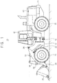
- FIG. 1 is a side view illustrating construction machinery in accordance with example embodiments.
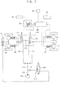
- FIG. 2 is a hydraulic circuit diagram illustrating a control system for the construction machinery in FIG. 1 .
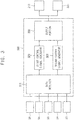
- FIG. 3 is a block diagram illustrating a controller of the control system in FIG. 2 .
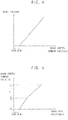
- FIG. 4 is a graph illustrating a brake pressure in response to a brake control signal outputted from the controller in FIG. 3 .
- FIG. 5 is a graph illustrating a brake control signal according to a brake pedal position of a driver, which is generated by the controller in FIG. 3 .
- FIG. 6 is a graph illustrating a conversion rate of a brake control signal with respect to a brake pedal position according to a vehicle speed, which is generated by the controller in FIG. 3 .
- FIG. 1 is a side view illustrating construction machinery in accordance with example embodiments.
- FIG. 2 is a hydraulic circuit diagram illustrating a control system for the construction machinery in FIG. 1 .
- FIG. 3 is a block diagram
- FIG. 7 is a graph illustrating a conversion rate of a brake control signal with respect to a brake pedal position according to a boom cylinder pressure, which is generated by the controller in FIG. 3 .
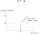
- FIG. 8 is a graph illustrating a conversion rate of a brake control signal with respect to a brake pedal position according to a boom angle, which is generated by the controller in FIG. 3 .
- the wheel loader 10 is illustrated in FIG. 1 , the control system for the construction machinery according to example embodiments may not limited thereto, and it may be understood that example embodiments may be applied to wheel type construction machinery such as a wheel excavator.
- wheel loader 10 will be described.
- a wheel loader 10 may include a front body 12 and a rear body 14 rotatably connected to each other.
- the front body 12 may include a work apparatus and a front wheel 70.
- the rear body 14 may include a driver cabin 40, an engine bay 50 and a rear wheel 72.
- the work apparatus may include a boom 20 and a bucket 30.
- the boom 20 may be freely pivotally attached to the front body 12, and the bucket 30 may be freely pivotally attached to an end portion of the boom 20.
- the boom 20 may be coupled to the front body 12 by a pair of boom cylinders 22, and the boom 20 may be pivoted upwardly and downwardly by expansion and contraction of the boom cylinders 22.
- a tilt arm 34 may be freely rotatably supported on the boom 20, almost at its central portion.
- One end portion of the tilt arm 34 may be coupled to the front body 12 by a pair of bucket cylinders 32 and another end portion of the tilt arm 34 may be coupled to the bucket 30 by a tilt rod, so that the bucket 30 may pivot (crowd and dump) as the bucket cylinder 32 expands and contracts.
- the front body 12 and the rear body 14 may be rotatably connected to each other through a center pin 16 so that the front body 12 may swing side to side with respect to the rear body 14 by expansion and contraction of a steering cylinder (not illustrated).
- a travel apparatus for propelling the wheel loader 10 may be mounted at the rear body 14.
- An engine 100 may be provided in the engine bay 50 to supply an output power to the travel apparatus.
- the travel apparatus may include a transmission connected to the engine, a propeller shaft, a front axle 60, a rear axle 70, etc.
- the output power of the engine may be transmitted to the front wheel 70 and the rear wheel 72 through the transmission, the propeller shaft, the front axle 60 and the rear axle 62, and thus the wheel loader 10 may travels.
- a control system for construction machinery may include a hydraulic pump 100 configured to supply a brake oil, a front brake device 80 and a rear brake device 82 configured to receive the brake oil to brake the front axle 60 and the rear axle 70 respectively, and a brake control apparatus configured to control the front brake device 80 and the rear brake device 82 in response to a manipulation of a driver.
- the brake control apparatus may include first and second brake lines 120, 122 through which the brake oil is supplied to the front brake device 80 and the rear brake device 82 respectively, first and second proportional flow control valves 210, 220 installed respectively in the first and second brake lines 120, 122 to control a flow rate of the brake oil in proportion to inputted first and second brake control signals, a sensing portion configured to detect work and travel information of the construction machinery, and a controller 300 configured to output the first and second brake control signals according to a brake manipulation signal of the driver and configured to control independently the first and second proportional flow control valves 210, 220 based on the work and travel information of the construction machinery detected by the sensing portion.
- the hydraulic pump 100 may be connected to the engine through a power transmission device.
- the output power of the engine may be transmitted to the hydraulic pump 100.
- the brake oil discharged from the hydraulic pump 100 may be distributed to the front brake device 80 and the rear brake device 82 through the first and second brake control valves 210, 220.
- the hydraulic pump 100 may be a pilot pump connected to an output shaft of the engine.
- the pilot pump may include a gear pump.
- a main hydraulic line 110 may be connected to the hydraulic pump 100 to introduce the brake oil.
- the main hydraulic line 110 may be divided into a brake line 112 and a parking brake line 114.
- the brake line 112 may be divided into the first and second brake lines 120, 122.
- the first brake line 120 may be connected to the front brake device 80, and the second brake line 122 may be connected to the rear brake device 82.
- the parking brake line 114 may be connected to a parking brake device 92.
- a brake control valve may be installed in the first and second brake lines 120, 122 to control the flow rate of the brake oil according to an inputted electronic control signal.
- the first proportional flow control valve 210 may be installed in the first brake line 120 to control the flow rate of the brake oil in proportion to the inputted first brake control signal.
- the second proportional flow control valve 220 may be installed in the second brake line 122 to control the flow rate of the brake oil in proportion to the inputted second brake control signal.
- the first and second proportional flow control valves 210, 212 may include a proportional electro flow control valve.
- the flow rate of the brake oil passing through the proportional electro flow control valve may be in proportion to the inputted electronic control signal, for example, a magnitude of current command value (mA).
- the controller 300 may output the current command values (mA) as the first and second brake control signals to the first and second proportional flow control valves 210, 212, and the first and second proportion flow control valves 210, 212 may control the flow rates of the brake oil in proportion to magnitudes of the inputted brake control signals.
- the controller 300 may output the first and second brake control signals in response to a brake manipulation signal of the driver.
- the brake control apparatus for the construction machinery may further include an electronic pedal device 90 configured to output the brake manipulation signal as an electronic signal in proportion to an angle change of a brake pedal by the driver.
- the electronic pedal device 90 may detect an ON signal and the angle change of the brake pedal and output the electronic signal.
- the detected angle information may be transmitted to the controller 300 through CAN (controller area network), LIN (local interconnect network), FlexRay, etc.
- the sensing portion may include a boom angle sensor 24, a boom cylinder sensor 26, a vehicle speed sensor 54 and an acceleration sensor 52 to detect the work and travel information of the construction machinery.
- the boom angle sensor 24 may detect a rotational angle of the boom 20 to provide information on a boom height.
- the boom angle sensor 24 may detect a change in magnetic field by rotation of the boom 20 to output a voltage value representing an angle ⁇ of the boom 20.
- the boom cylinder pressure sensor 26 may detect a pressure of the boom cylinder 22.
- the boom cylinder pressure sensor 26 may detect a change in pressure of the boom cylinder 22 by live load of the bucket 30.
- the vehicle speed sensor 54 may detect speed information of the vehicle.
- the acceleration sensor 52 may be installed in the driver cabin 40 to detect an inclination angle of the vehicle with respect to a gravitational direction, a pitching rate of the vehicle, etc.
- the controller 300 may control independently the first and second proportional flow control valves 210, 220 based on the work and travel information of the construction machinery detected by the sensing portion.
- the controller 300 may include a data receiver 310 configured to receive the brake manipulation signal in proportion to the brake pedal manipulation amount of the driver from the electronic pedal device 90 and the work and travel information signals of the construction machinery detected by the sensing portion, first and second control signal generators 320, 322 configured to generate the first and second brake control signals based on the work and travel information of the construction machinery detected by the sensing portion respectively, and an output portion 330 configured to output the first and second brake control signals to the first and second brake control valves 210, 220 respectively.
- the first control signal generator 320 may convert the brake manipulation signal at a first conversion ratio based on the work and travel information of the construction machinery detected by the sensing portion to generate the first brake control signal.
- the second control signal generator 322 may convert the brake manipulation signal at a second conversion ratio based on the work and travel information of the construction machinery detected by the sensing portion to generate the second brake control signal.
- the first conversion ratio and the second conversion ratio may be adjusted to be identical to or different from each other according to the work and travel information of the construction machinery.
- the brake control apparatus for construction machinery may further include the parking brake line 114 through which the brake oil is supplied to the parking brake device 92, and a proportional direction control valve 230 installed in the parking brake line 114 to supply or block the brake oil according to an inputted parking control signal.
- the proportional direction control valve 230 may include a solenoid directional control valve.
- An ON - OFF operation of the solenoid directional control valve may be determined by the inputted parking control signal, for example, a current command value (mA).
- the controller 300 may output the parking brake signal in case of a parking braking condition or an emergency occurrence, and the proportional direction control valve 230 may control an operation of the parking brake device 92 according to the parking control signal.
- an initial section of a brake pedal displacement may be set to a dead zone to prevent braking due to driver's mistakes, and in a section subsequent to the initial section, brake pressures of the front and rear brake devices 80, 82 may be controlled in proportion to the brake pedal displacement by the driver.
- the brake pressures (bar) of the front and rear brake devices 80, 82 may be maintained at 0 when the brake control signal (brake control command value (mA)) is within the initial section (dead zone).
- the brake control signal may be controlled for each section such that different brake pressures are generated in an initial brake section I and a main brake section II.
- the brake control signal (brake control command value (mA)) may be maintained at 0 when the brake manipulation signal (brake pedal displacement (%)) is within the initial section (dead zone), the brake control signal may be converted at a first ratio from the brake manipulation signal when the brake manipulation signal is within the initial brake section (Section I) after the dead zone, and the brake control signal may be converted at a second ratio less than the first ratio from the brake manipulation signal when the brake manipulation signal is within the main brake section (Section II).
- a brake control may be performed more quickly.
- brake forces of the front axle 60 and the rear axle 62 may be independently controlled at a predetermined vehicle speed or more.
- the first control signal generator 320 may convert the brake manipulation signal at a first conversion ratio to generate and output the first brake control signal
- the second control signal generator 322 may convert the brake manipulation signal at a second conversion ratio to generate and output the second brake control signal.
- the first conversion ratio and the second conversion ratio may be controlled to be identical to each other when the vehicle speed is less than a predetermined value, and The first conversion ratio and the second conversion ratio may be controlled to be different from each other when the vehicle speed is the predetermined value or more.
- the first conversion ratio may be controlled to increase as the vehicle speed increases and the second conversion ratio may be controlled to decrease as the vehicle speed increases when the vehicle speed is the predetermined value or more.
- the brake force of the front axle 60 may be controlled to increase more relatively to the brake force of the rear axle 62 to thereby perform efficient brake control.
- a brake force of the front axle 60 may be controlled to increase in proportion to the live load when the live load of the bucket is a predetermined value or more.
- the first conversion ratio may be controlled to increase in proportion to the live load of the bucket 30 when the live load of the bucket 30 is 50% or more based on a boom cylinder pressure.
- the brake force of the front axle 60 may be controlled to increase to thereby perform efficient brake control.
- a brake force of the front axle 60 may be controlled to increase in proportion to the height of the bucket 30 when the height of the bucket 30 from a ground surface is a predetermined height or more.
- the first conversion ratio may be controlled to increase as the height of the bucket 30 increases when the height of the bucket 30 is 40% or more based on a boom angle.
- the brake force of the front axle 60 may be controlled to increase to thereby perform efficient brake control.
- the controller 300 may execute a slope slip prevention mode and output the first and second brake control signals to operate the front brake device 80 and the rear brake device 82.
- the controller 300 may determine whether the slope slip prevention mode is satisfied (slope condition (5 degrees or more), vehicle speed state (stationary state, 0 km/h), brake pedal input condition (100%, 2 seconds or more), acceleration pedal input condition (0%), and may determine an entry time of the slope slip prevention mode.
- slope condition 5 degrees or more
- vehicle speed state stationary state, 0 km/h
- brake pedal input condition 100%, 2 seconds or more
- acceleration pedal input condition 0%
- the controller 300 may output the first and second brake control signals to the first and second brake control valves 210, 212 respectively.
- the front and rear brake devices 80, 82 may operate to prevent the construction machinery 10 from being slipped.
- the controller 300 may terminate the slope slip prevention mode operation when the controller 300 receives any one of a brake pedal input condition (newly inputted brake pedal position 80% or more), an acceleration pedal input (50% or more) and a lever change of a FNR travel lever.
- the controller 300 may output the first and second brake control signals or the parking control signal to prevent an occurrence of a safety accident.
- the brake control apparatus for the construction machinery may control independently the front and rear brake devices 80, 82 using electro hydraulic brake control manner. Additionally, when an unintended situation occurs, a safety accident may be prevented through the parking solenoid valve 230. Thus, it may be possible to provide a vehicle braking control for unmanned/automated equipment of the construction machinery.
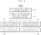
- FIG. 9 is a flow chart illustrating a brake control method for construction machinery in accordance with example embodiments.
- a brake manipulation signal of a driver and work and travel information of construction machinery may be received (S100).
- the driver may input the brake manipulation signal for the front and rear brake devices 80, 82 through an electronic pedal device 90.
- the work and travel information of the construction machinery may be obtained through a sensing portion installed in the construction machinery.
- a rotational angle of a boom 20 may be detected by a boom angle sensor 24 to obtain information on a boom height.
- a pressure of the boom cylinder 22 may be detected by a boom cylinder pressure sensor 26 to obtain information on live load of a bucket 30.
- Speed information of the vehicle may be obtained by a vehicle speed sensor 54.
- Information on an inclination angle of the vehicle with respect to a gravitational direction, a pitching rate of the vehicle, etc. may be obtained by an acceleration sensor 54.
- first and second brake control signals in response to the brake manipulation signal may be generated respectively based on the information (S 110), a first proportional flow control valve 210 may be operated according to the first brake control signal (S 120), and a second proportional flow control valve 220 may be operated according to the second brake control signal (S 122). Then, operations of front and rear brake devices 80, 82 may be controlled by a brake oil (S130, S132).
- the brake manipulation signal may be converted at a first conversion ratio to generate the first brake control signal and the brake manipulation signal may be converted at a second conversion ratio to generate the second brake control signal based on the work and travel information of the construction machinery.
- the first conversion ratio and the second conversion ratio may be adjusted to be identical to or different from each other according to the work and travel information of the construction machinery.
- the first and second brake control valves 210, 212 may control flow rates of the brake oil in proportion to magnitudes of the first and second brake control signals.
- brake forces of a front axle 60 and a rear axle 62 may be controlled independently when the vehicle speed is a predetermined value or more.
- the first conversion ratio may be controlled to increase as the vehicle speed increases and the second conversion ratio may be controlled to decrease as the vehicle speed increases when the vehicle speed is the predetermined value or more.
- the brake force of the front axle 60 may be controlled to increase more relatively to the brake force of the rear axle 62 to thereby perform efficient brake control.
- the brake force of the front axle 60 may be controlled to increase in proportion to the live load of the bucket 30 when the live load of the bucket 30 is a predetermined value or more.
- the first conversion ratio may be controlled to increase in proportion to the live load of the bucket 30 when the live load of the bucket 30 is 50% or more.
- the brake force of the front axle 60 may be controlled to increase to thereby perform efficient brake control.
- the brake force of the front axle 60 may be controlled to increase in proportion to a height of the bucket 30 when the height of the bucket 30 from a ground surface is a predetermined height or more.
- the first conversion ratio may be controlled to increase as the height of the bucket 30 increases when the height of the bucket 30 is 40% or more.
- the brake force of the front axle 60 may be controlled to increase to thereby perform efficient brake control.
- a slope slip prevention mode may be executed to output the first and second brake control signals to operate the front brake device 80 and the rear brake device 82.
- an entry condition of the slope slip prevention mode for example, slope condition (5 degrees or more), vehicle speed state (stationary state, 0 km/h), brake pedal input condition (100%, 2 seconds or more), acceleration pedal input condition (0%)
- an entry time of the slope slip prevention mode may be determined.
- termination conditions of the slope slip prevention mode operation for example, a brake pedal input condition (newly inputted brake pedal position 80% or more), an acceleration pedal input (50% or more), a lever change of a FNR travel lever, etc. is satisfied, the slope slip prevention mode operation may be terminated.
- the first and second brake control signals or the parking control signal may be outputted to prevent an occurrence of a safety accident.
Landscapes
- Engineering & Computer Science (AREA)
- Transportation (AREA)
- Mechanical Engineering (AREA)
- Mining & Mineral Resources (AREA)
- Civil Engineering (AREA)
- General Engineering & Computer Science (AREA)
- Structural Engineering (AREA)
- Physics & Mathematics (AREA)
- Fluid Mechanics (AREA)
- Operation Control Of Excavators (AREA)
- Regulating Braking Force (AREA)
- Fluid-Pressure Circuits (AREA)
Abstract
Description
- The present invention relates to a brake control system for construction machinery and a brake control method for construction machinery. More particularly, the present invention relates to a brake control system and a brake control method for a wheel type of construction machinery.
- In a conventional hydraulic brake control apparatus for construction machinery, a driver may control a hydraulic brake valve using a brake pedal in a manual brake manner. However, because the hydraulic brake valve supplies a brake oil to both a front brake device and a rear brake device, it may be difficult to precisely control independently the front and rear brake devices according to conditions of the construction machinery.
- An object of the present invention provides an electro hydraulic brake control system for construction machinery capable of controlling independently a front brake device and a rear brake device.
- Another object of the present invention provides a brake control method for construction machinery using the above brake control system.
- According to example embodiments, a brake control apparatus for construction machinery, includes first and second brake lines through which a brake oil is supplied to a front brake device and a rear brake device of the construction machinery, first and second proportional flow control valves installed respectively in the first and second brake lines to control a flow rate of the brake oil in proportion to inputted first and second brake control signals, a sensing portion configured to detect work and travel information of the construction machinery, and a controller configured to output the first and second brake control signals in response to a brake manipulation signal of a driver, and configured to control independently the first and second proportional flow control valves based on the work and travel information of the construction machinery detected by the sensing portion.
- In example embodiments, the controller may convert the brake manipulation signal at a first conversion ratio to generate and output the first brake control signal and may convert the brake manipulation signal at a second conversion ratio to generate and output the second brake control signal.
- In example embodiments, the first conversion ratio and the second conversion ratio may be changed depending on a magnitude of the brake manipulation signal.
- In example embodiments, the first and second conversion ratios may have a first magnitude when the brake manipulation signal is less than a predetermined value, and the first and second conversion ratios may have a second magnitude when the brake manipulation signal is the predetermined value or more.
- In example embodiments, the first and second conversion ratios may be adjusted to change according to a vehicle speed of the construction machinery.
- In example embodiments, the first conversion ratio may increase as the vehicle speed increases and the second conversion ratio may decrease as the vehicle speed increases.
- In example embodiments, the first conversion ratio and the second conversion ratio may be identical to each other when the vehicle speed is less than a predetermined value.
- In example embodiments, the first and second conversion ratios may be adjusted to change according to live load of a bucket of the construction machinery.
- In example embodiments, the first and second conversion ratios may be adjusted to change according to a height of a bucket of the construction machinery.
- In example embodiments, in case that the construction machinery is on a slope, when the controller receives the brake manipulation signal for a certain period of time, the controller may execute a slope slip prevention mode and output the first and second brake control signals to operate the front brake device and the rear brake device.
- In example embodiments, the controller may include a first control signal generator configured to convert the brake manipulation signal at a first conversion ratio based on the work and travel information of the construction machinery detected by the sensing portion to generate the first brake control signal, and a second control signal generator configured to convert the brake manipulation signal at a second conversion ratio based on the work and travel information of the construction machinery detected by the sensing portion to generate the second brake control signal.
- In example embodiments, the sensing portion may include at least one of a boom angle sensor, a boom cylinder pressure sensor, a vehicle speed sensor and an acceleration sensor.
- In example embodiments, the brake control apparatus for construction machinery may further include a parking brake line through which the brake oil is supplied to a parking brake device of the construction machinery, and a proportional direction control valve installed in the parking brake line to supply or block the brake oil according to an inputted parking control signal. The controller may output the parking control signal in case of an emergency occurrence.
- In example embodiments, the brake control apparatus for construction machinery may further include an electronic pedal device configured to output the brake manipulation signal as an electronic signal in proportion to an angle change of a brake pedal by the driver.
- According to example embodiments, a brake control apparatus for construction machinery includes a hydraulic pump configured to supply a brake oil, first and second brake lines connected to the hydraulic pump to supply the brake oil to a front brake device and a rear brake device of the construction machinery therethrough, first and second proportional flow control valves installed respectively in the first and second brake lines to control a flow rate of the brake oil in proportion to inputted first and second brake control signals, a sensing portion including a boom angle sensor, a bucket angle sensor and a vehicle speed sensor and configured to detect work and travel information of the construction machinery, an electronic pedal device configured to output a brake manipulation signal as an electronic signal in proportion to an angle change of a brake pedal by a driver, and a controller configured to output the first and second brake control signals in response to the brake manipulation signal of the electronic pedal device, and configured to control independently the first and second proportional flow control valves based on the work and travel information of the construction machinery detected by the boom angle sensor, the bucket angle sensor, the vehicle speed sensor and the electronic pedal device.
- According to example embodiments, in a brake control method for construction machinery, a hydraulic system is provided, the hydraulic system including first and second brake lines through which a brake oil is supplied to a front brake device and a rear brake device of the construction machinery and first and second proportional flow control valves installed respectively in the first and second brake lines to control a flow rate of the brake oil in proportion to inputted first and second brake control signals. Work and travel information of the construction machinery are detected. The first and second brake control signals are outputted based on the work and travel information of construction machinery in response to a brake manipulation signal in order to independently the first and second proportional flow control valves.
- In example embodiments, outputting the first and second brake control signals may include converting the brake manipulation signal at a first conversion ratio to generate and output the first brake control signal and converting the brake manipulation signal at a second conversion ratio to generate and output the second brake control signal.
- In example embodiments, the first conversion ratio and the second conversion ratio may be changed depending on at least one of a magnitude of the brake manipulation signal, a vehicle speed of the construction machinery, live load of a bucket of the construction machinery and a height of a bucket of the construction machinery.
- In example embodiments, outputting the first and second brake control signals may include, in case that the construction machinery is on a slope, when the brake manipulation signal is received for a certain period of time, executing a slope slip prevention mode and outputting the first and second brake control signals to operate the front brake device and the rear brake device.
- In example embodiments, the brake control method for construction machinery may further include receiving the brake manipulation signal as an electronic signal in proportion to an angle change of a brake pedal by the driver.
- According to example embodiments, in a brake control apparatus and a brake control method for construction machinery, front and rear brake devices may be independently controlled using electro hydraulic brake control manner in consideration of work and travel information of the construction machinery. Additionally, when an unintended situation occurs, a safety accident may be prevented through a parking solenoid valve.
- Thus, it may be possible to provide a vehicle braking control for unmanned/automated equipment of the construction machinery.
- However, the effect of the invention may not be limited thereto, and may be expanded without being deviated from the concept and the scope of the present invention.
-
-
FIG. 1 is a side view illustrating construction machinery in accordance with example embodiments. -
FIG. 2 is a hydraulic circuit diagram illustrating a control system for the construction machinery inFIG. 1 . -
FIG. 3 is a block diagram illustrating a controller of the control system inFIG. 2 . -
FIG. 4 is a graph illustrating a brake pressure in response to a brake control signal outputted from the controller inFIG. 3 . -
FIG. 5 is a graph illustrating a brake control signal according to a brake pedal position of a driver, which is generated by the controller inFIG. 3 . -
FIG. 6 is a graph illustrating a conversion rate of a brake control signal with respect to a brake pedal position according to a vehicle speed, which is generated by the controller inFIG. 3 . -
FIG. 7 is a graph illustrating a conversion rate of a brake control signal with respect to a brake pedal position according to a boom cylinder pressure, which is generated by the controller inFIG. 3 . -
FIG. 8 is a graph illustrating a conversion rate of a brake control signal with respect to a brake pedal position according to a boom angle, which is generated by the controller inFIG. 3 . -
FIG. 9 is a flow chart illustrating a brake control method for construction machinery in accordance with example embodiments. - Hereinafter, preferable embodiments of the present invention will be explained in detail with reference to the accompanying drawings.
- In the drawings, the sizes and relative sizes of components or elements may be exaggerated for clarity.
- It will be understood that, although the terms first, second, third, etc. may be used herein to describe various elements, components, regions, layers and/or sections, these elements, components, regions, layers and/or sections should not be limited by these terms. These terms are only used to distinguish one element, component, region, layer or section from another element, component, region, layer or section. Thus, a first element, component, region, layer or section discussed below could be termed a second element, component, region, layer or section without departing from the teachings of example embodiments.
- The terminology used herein is for the purpose of describing particular example embodiments only and is not intended to be limiting of example embodiments. As used herein, the singular forms "a," "an" and "the" are intended to include the plural forms as well, unless the context clearly indicates otherwise. It will be further understood that the terms "comprises" and/or "comprising," when used in this specification, specify the presence of stated features, integers, steps, operations, elements, and/or components, but do not preclude the presence or addition of one or more other features, integers, steps, operations, elements, components, and/or groups thereof.
- Unless otherwise defined, all terms (including technical and scientific terms) used herein have the same meaning as commonly understood by one of ordinary skill in the art to which example embodiments belong. It will be further understood that terms, such as those defined in commonly used dictionaries, should be interpreted as having a meaning that is consistent with their meaning in the context of the relevant art and will not be interpreted in an idealized or overly formal sense unless expressly so defined herein.
- Example embodiments may, however, be embodied in many different forms and should not be construed as limited to example embodiments set forth herein. Rather, these example embodiments are provided so that this disclosure will be thorough and complete, and will fully convey the scope of example embodiments to those skilled in the art.
-
FIG. 1 is a side view illustrating construction machinery in accordance with example embodiments.FIG. 2 is a hydraulic circuit diagram illustrating a control system for the construction machinery inFIG. 1 .FIG. 3 is a block diagram illustrating a controller of the control system inFIG. 2 .FIG. 4 is a graph illustrating a brake pressure in response to a brake control signal outputted from the controller inFIG. 3 .FIG. 5 is a graph illustrating a brake control signal according to a brake pedal position of a driver, which is generated by the controller inFIG. 3 .FIG. 6 is a graph illustrating a conversion rate of a brake control signal with respect to a brake pedal position according to a vehicle speed, which is generated by the controller inFIG. 3 .FIG. 7 is a graph illustrating a conversion rate of a brake control signal with respect to a brake pedal position according to a boom cylinder pressure, which is generated by the controller inFIG. 3 .FIG. 8 is a graph illustrating a conversion rate of a brake control signal with respect to a brake pedal position according to a boom angle, which is generated by the controller inFIG. 3 . Although thewheel loader 10 is illustrated inFIG. 1 , the control system for the construction machinery according to example embodiments may not limited thereto, and it may be understood that example embodiments may be applied to wheel type construction machinery such as a wheel excavator. Hereinafter, for convenience of description, only thewheel loader 10 will be described. - Referring to
FIG. 1 , awheel loader 10 may include afront body 12 and arear body 14 rotatably connected to each other. Thefront body 12 may include a work apparatus and afront wheel 70. Therear body 14 may include adriver cabin 40, anengine bay 50 and arear wheel 72. - The work apparatus may include a
boom 20 and abucket 30. Theboom 20 may be freely pivotally attached to thefront body 12, and thebucket 30 may be freely pivotally attached to an end portion of theboom 20. Theboom 20 may be coupled to thefront body 12 by a pair ofboom cylinders 22, and theboom 20 may be pivoted upwardly and downwardly by expansion and contraction of theboom cylinders 22. Atilt arm 34 may be freely rotatably supported on theboom 20, almost at its central portion. One end portion of thetilt arm 34 may be coupled to thefront body 12 by a pair ofbucket cylinders 32 and another end portion of thetilt arm 34 may be coupled to thebucket 30 by a tilt rod, so that thebucket 30 may pivot (crowd and dump) as thebucket cylinder 32 expands and contracts. - The
front body 12 and therear body 14 may be rotatably connected to each other through acenter pin 16 so that thefront body 12 may swing side to side with respect to therear body 14 by expansion and contraction of a steering cylinder (not illustrated). - A travel apparatus for propelling the
wheel loader 10 may be mounted at therear body 14. Anengine 100 may be provided in theengine bay 50 to supply an output power to the travel apparatus. The travel apparatus may include a transmission connected to the engine, a propeller shaft, afront axle 60, arear axle 70, etc. The output power of the engine may be transmitted to thefront wheel 70 and therear wheel 72 through the transmission, the propeller shaft, thefront axle 60 and therear axle 62, and thus thewheel loader 10 may travels. - As illustrated in
FIG. 2 , a control system for construction machinery may include ahydraulic pump 100 configured to supply a brake oil, afront brake device 80 and arear brake device 82 configured to receive the brake oil to brake thefront axle 60 and therear axle 70 respectively, and a brake control apparatus configured to control thefront brake device 80 and therear brake device 82 in response to a manipulation of a driver. - The brake control apparatus may include first and
second brake lines front brake device 80 and therear brake device 82 respectively, first and second proportionalflow control valves second brake lines controller 300 configured to output the first and second brake control signals according to a brake manipulation signal of the driver and configured to control independently the first and second proportionalflow control valves - In example embodiments, the
hydraulic pump 100 may be connected to the engine through a power transmission device. The output power of the engine may be transmitted to thehydraulic pump 100. The brake oil discharged from thehydraulic pump 100 may be distributed to thefront brake device 80 and therear brake device 82 through the first and secondbrake control valves hydraulic pump 100 may be a pilot pump connected to an output shaft of the engine. The pilot pump may include a gear pump. - In particular, a main
hydraulic line 110 may be connected to thehydraulic pump 100 to introduce the brake oil. The mainhydraulic line 110 may be divided into abrake line 112 and aparking brake line 114. Thebrake line 112 may be divided into the first andsecond brake lines first brake line 120 may be connected to thefront brake device 80, and thesecond brake line 122 may be connected to therear brake device 82. Additionally, as described later, theparking brake line 114 may be connected to aparking brake device 92. - A brake control valve may be installed in the first and
second brake lines flow control valve 210 may be installed in thefirst brake line 120 to control the flow rate of the brake oil in proportion to the inputted first brake control signal. The second proportionalflow control valve 220 may be installed in thesecond brake line 122 to control the flow rate of the brake oil in proportion to the inputted second brake control signal. - For example, the first and second proportional
flow control valves 210, 212 may include a proportional electro flow control valve. The flow rate of the brake oil passing through the proportional electro flow control valve may be in proportion to the inputted electronic control signal, for example, a magnitude of current command value (mA). As described later, thecontroller 300 may output the current command values (mA) as the first and second brake control signals to the first and second proportionalflow control valves 210, 212, and the first and second proportionflow control valves 210, 212 may control the flow rates of the brake oil in proportion to magnitudes of the inputted brake control signals. - In example embodiments, the
controller 300 may output the first and second brake control signals in response to a brake manipulation signal of the driver. The brake control apparatus for the construction machinery may further include anelectronic pedal device 90 configured to output the brake manipulation signal as an electronic signal in proportion to an angle change of a brake pedal by the driver. For example, when the driver presses the brake pedal, theelectronic pedal device 90 may detect an ON signal and the angle change of the brake pedal and output the electronic signal. The detected angle information may be transmitted to thecontroller 300 through CAN (controller area network), LIN (local interconnect network), FlexRay, etc. - In example embodiments, the sensing portion may include a
boom angle sensor 24, aboom cylinder sensor 26, avehicle speed sensor 54 and anacceleration sensor 52 to detect the work and travel information of the construction machinery. - The
boom angle sensor 24 may detect a rotational angle of theboom 20 to provide information on a boom height. Theboom angle sensor 24 may detect a change in magnetic field by rotation of theboom 20 to output a voltage value representing an angle θ of theboom 20. - The boom
cylinder pressure sensor 26 may detect a pressure of theboom cylinder 22. The boomcylinder pressure sensor 26 may detect a change in pressure of theboom cylinder 22 by live load of thebucket 30. - The
vehicle speed sensor 54 may detect speed information of the vehicle. Theacceleration sensor 52 may be installed in thedriver cabin 40 to detect an inclination angle of the vehicle with respect to a gravitational direction, a pitching rate of the vehicle, etc. - In example embodiments, the
controller 300 may control independently the first and second proportionalflow control valves controller 300 may include adata receiver 310 configured to receive the brake manipulation signal in proportion to the brake pedal manipulation amount of the driver from theelectronic pedal device 90 and the work and travel information signals of the construction machinery detected by the sensing portion, first and secondcontrol signal generators output portion 330 configured to output the first and second brake control signals to the first and secondbrake control valves - For example, the first
control signal generator 320 may convert the brake manipulation signal at a first conversion ratio based on the work and travel information of the construction machinery detected by the sensing portion to generate the first brake control signal. The secondcontrol signal generator 322 may convert the brake manipulation signal at a second conversion ratio based on the work and travel information of the construction machinery detected by the sensing portion to generate the second brake control signal. The first conversion ratio and the second conversion ratio may be adjusted to be identical to or different from each other according to the work and travel information of the construction machinery. - In example embodiments, the brake control apparatus for construction machinery may further include the
parking brake line 114 through which the brake oil is supplied to theparking brake device 92, and a proportionaldirection control valve 230 installed in theparking brake line 114 to supply or block the brake oil according to an inputted parking control signal. - For example, the proportional
direction control valve 230 may include a solenoid directional control valve. An ON - OFF operation of the solenoid directional control valve may be determined by the inputted parking control signal, for example, a current command value (mA). - The
controller 300 may output the parking brake signal in case of a parking braking condition or an emergency occurrence, and the proportionaldirection control valve 230 may control an operation of theparking brake device 92 according to the parking control signal. - Hereinafter, a brake control method for construction machinery using the brake control apparatus in
FIGS. 2 and3 will be explained. - As illustrated in
FIG. 4 , first, an initial section of a brake pedal displacement may be set to a dead zone to prevent braking due to driver's mistakes, and in a section subsequent to the initial section, brake pressures of the front andrear brake devices - For example, the brake pressures (bar) of the front and
rear brake devices - As illustrated in
FIG. 5 , the brake control signal may be controlled for each section such that different brake pressures are generated in an initial brake section I and a main brake section II. - For example, the brake control signal (brake control command value (mA)) may be maintained at 0 when the brake manipulation signal (brake pedal displacement (%)) is within the initial section (dead zone), the brake control signal may be converted at a first ratio from the brake manipulation signal when the brake manipulation signal is within the initial brake section (Section I) after the dead zone, and the brake control signal may be converted at a second ratio less than the first ratio from the brake manipulation signal when the brake manipulation signal is within the main brake section (Section II). Thus, in the initial brake section (Section I), a brake control may be performed more quickly.
- As illustrated in
FIG. 6 , because loads applied to thefront axle 60 and therear axle 62 during braking are different from each other depending on the vehicle speed, brake forces of thefront axle 60 and therear axle 62 may be independently controlled at a predetermined vehicle speed or more. - In particular, the first
control signal generator 320 may convert the brake manipulation signal at a first conversion ratio to generate and output the first brake control signal, and the secondcontrol signal generator 322 may convert the brake manipulation signal at a second conversion ratio to generate and output the second brake control signal. The first conversion ratio and the second conversion ratio may be controlled to be identical to each other when the vehicle speed is less than a predetermined value, and The first conversion ratio and the second conversion ratio may be controlled to be different from each other when the vehicle speed is the predetermined value or more. - For example, the first conversion ratio may be controlled to increase as the vehicle speed increases and the second conversion ratio may be controlled to decrease as the vehicle speed increases when the vehicle speed is the predetermined value or more. Thus, as the vehicle speed increases, the brake force of the
front axle 60 may be controlled to increase more relatively to the brake force of therear axle 62 to thereby perform efficient brake control. - As illustrated in
FIG. 7 , because load applied to thefront axle 60 varies depending on live load of thebucket 30, a brake force of thefront axle 60 may be controlled to increase in proportion to the live load when the live load of the bucket is a predetermined value or more. - In particular, the first conversion ratio may be controlled to increase in proportion to the live load of the
bucket 30 when the live load of thebucket 30 is 50% or more based on a boom cylinder pressure. Thus, as the live load of the bucket increases, the brake force of thefront axle 60 may be controlled to increase to thereby perform efficient brake control. - As illustrated in
FIG. 8 , because loads applied to thefront axle 60 and therear axle 62 during braking are different from each other depending on a height of thebucket 30, a brake force of thefront axle 60 may be controlled to increase in proportion to the height of thebucket 30 when the height of thebucket 30 from a ground surface is a predetermined height or more. - In particular, the first conversion ratio may be controlled to increase as the height of the
bucket 30 increases when the height of thebucket 30 is 40% or more based on a boom angle. Thus, as the height of the bucket increases, the brake force of thefront axle 60 may be controlled to increase to thereby perform efficient brake control. - In example embodiments, in case that the construction machinery is on a slope, when the
controller 300 receives the brake manipulation signal for a certain period of time, thecontroller 300 may execute a slope slip prevention mode and output the first and second brake control signals to operate thefront brake device 80 and therear brake device 82. - In particular, the
controller 300 may determine whether the slope slip prevention mode is satisfied (slope condition (5 degrees or more), vehicle speed state (stationary state, 0 km/h), brake pedal input condition (100%, 2 seconds or more), acceleration pedal input condition (0%), and may determine an entry time of the slope slip prevention mode. - In the slop slip prevention mode, the
controller 300 may output the first and second brake control signals to the first and secondbrake control valves 210, 212 respectively. Thus, even if the driver does not press the brake pedal, the front andrear brake devices construction machinery 10 from being slipped. - The
controller 300 may terminate the slope slip prevention mode operation when thecontroller 300 receives any one of a brake pedal input condition (newly inputtedbrake pedal position 80% or more), an acceleration pedal input (50% or more) and a lever change of a FNR travel lever. - In example embodiments, when an unexpected situation occurs regardless of the driver's will, the
controller 300 may output the first and second brake control signals or the parking control signal to prevent an occurrence of a safety accident. - As mentioned above, the brake control apparatus for the construction machinery may control independently the front and
rear brake devices parking solenoid valve 230. Thus, it may be possible to provide a vehicle braking control for unmanned/automated equipment of the construction machinery. - Hereinafter, a brake control method for construction machinery using the brake control apparatus in
FIGS. 2 and3 will be explained. -
FIG. 9 is a flow chart illustrating a brake control method for construction machinery in accordance with example embodiments. - Referring to
FIGS. 2 ,3 and9 , a brake manipulation signal of a driver and work and travel information of construction machinery may be received (S100). - In example embodiments, the driver may input the brake manipulation signal for the front and
rear brake devices electronic pedal device 90. The work and travel information of the construction machinery may be obtained through a sensing portion installed in the construction machinery. - For example, a rotational angle of a
boom 20 may be detected by aboom angle sensor 24 to obtain information on a boom height. A pressure of theboom cylinder 22 may be detected by a boomcylinder pressure sensor 26 to obtain information on live load of abucket 30. Speed information of the vehicle may be obtained by avehicle speed sensor 54. Information on an inclination angle of the vehicle with respect to a gravitational direction, a pitching rate of the vehicle, etc. may be obtained by anacceleration sensor 54. - Then, first and second brake control signals in response to the brake manipulation signal may be generated respectively based on the information (S 110), a first proportional
flow control valve 210 may be operated according to the first brake control signal (S 120), and a second proportionalflow control valve 220 may be operated according to the second brake control signal (S 122). Then, operations of front andrear brake devices - In example embodiments, the brake manipulation signal may be converted at a first conversion ratio to generate the first brake control signal and the brake manipulation signal may be converted at a second conversion ratio to generate the second brake control signal based on the work and travel information of the construction machinery. The first conversion ratio and the second conversion ratio may be adjusted to be identical to or different from each other according to the work and travel information of the construction machinery. The first and second
brake control valves 210, 212 may control flow rates of the brake oil in proportion to magnitudes of the first and second brake control signals. - For example, brake forces of a
front axle 60 and arear axle 62 may be controlled independently when the vehicle speed is a predetermined value or more. The first conversion ratio may be controlled to increase as the vehicle speed increases and the second conversion ratio may be controlled to decrease as the vehicle speed increases when the vehicle speed is the predetermined value or more. Thus, as the vehicle speed increases, the brake force of thefront axle 60 may be controlled to increase more relatively to the brake force of therear axle 62 to thereby perform efficient brake control. - The brake force of the
front axle 60 may be controlled to increase in proportion to the live load of thebucket 30 when the live load of thebucket 30 is a predetermined value or more. The first conversion ratio may be controlled to increase in proportion to the live load of thebucket 30 when the live load of thebucket 30 is 50% or more. Thus, as the live load of the bucket increases, the brake force of thefront axle 60 may be controlled to increase to thereby perform efficient brake control. - The brake force of the
front axle 60 may be controlled to increase in proportion to a height of thebucket 30 when the height of thebucket 30 from a ground surface is a predetermined height or more. The first conversion ratio may be controlled to increase as the height of thebucket 30 increases when the height of thebucket 30 is 40% or more. Thus, as the height of the bucket increases, the brake force of thefront axle 60 may be controlled to increase to thereby perform efficient brake control. - In case that the construction machinery is on a slope, when the brake manipulation signal is received for a certain period of time, a slope slip prevention mode may be executed to output the first and second brake control signals to operate the
front brake device 80 and therear brake device 82. - In particular, it may be determined whether an entry condition of the slope slip prevention mode is satisfied (for example, slope condition (5 degrees or more), vehicle speed state (stationary state, 0 km/h), brake pedal input condition (100%, 2 seconds or more), acceleration pedal input condition (0%)), and an entry time of the slope slip prevention mode may be determined. Additionally, when any one of termination conditions of the slope slip prevention mode operation, for example, a brake pedal input condition (newly inputted
brake pedal position 80% or more), an acceleration pedal input (50% or more), a lever change of a FNR travel lever, etc. is satisfied, the slope slip prevention mode operation may be terminated. - Additionally, when an unexpected situation occurs regardless of the driver's will, the first and second brake control signals or the parking control signal may be outputted to prevent an occurrence of a safety accident.
- The present invention has been explained with reference to preferable embodiments, however, those skilled in the art may understand that the present invention may be modified or changed without being deviated from the concept and the scope of the present invention disclosed in the following claims.
-
- 10: wheel loader 12: front body
- 14: rear body 20: boom
- 22: boom cylinder 24: boom angle sensor
- 30: bucket 32: bucket cylinder
- 34: tilt arm 36: bucket angle sensor
- 40: driver cabin 50: engine bay
- 52: acceleration sensor 54: speed sensor
- 60: front axle 62: rear axle
- 70: front wheel 72: rear wheel
- 80: front brake device 82: rear brake device
- 90: electronic pedal device 92: parking brake device
- 100: hydraulic pump 110: main hydraulic line
- 112: brake line 114: parking brake line
- 120: first brake line 122: second brake line
- 200: brake control valve 210: first brake control valve
- 220: second brake control valve 230: proportional direction control valve
- 300: controller 310: data receiver
- 320: first control signal generator 322: second control signal generator
- 340: output portion
Claims (20)
- A brake control apparatus for construction machinery, comprising:first and second brake lines through which a brake oil is supplied to a front brake device and a rear brake device of the construction machinery;first and second proportional flow control valves installed respectively in the first and second brake lines to control a flow rate of the brake oil in proportion to inputted first and second brake control signals;a sensing portion configured to detect work and travel information of the construction machinery; anda controller configured to output the first and second brake control signals in response to a brake manipulation signal of a driver, and configured to control independently the first and second proportional flow control valves based on the work and travel information of the construction machinery detected by the sensing portion.
- The brake control apparatus for construction machinery of claim 1, wherein the controller converts the brake manipulation signal at a first conversion ratio to generate and output the first brake control signal and converts the brake manipulation signal at a second conversion ratio to generate and output the second brake control signal.
- The brake control apparatus for construction machinery of claim 2, wherein the first conversion ratio and the second conversion ratio are changed depending on a magnitude of the brake manipulation signal.
- The brake control apparatus for construction machinery of claim 3, wherein the first and second conversion ratios have a first magnitude when the brake manipulation signal is less than a predetermined value, and the first and second conversion ratios have a second magnitude when the brake manipulation signal is the predetermined value or more.
- The brake control apparatus for construction machinery of claim 2, wherein the first and second conversion ratios are adjusted to change according to a vehicle speed of the construction machinery.
- The brake control apparatus for construction machinery of claim 5, wherein the first conversion ratio increases as the vehicle speed increases and the second conversion ratio decreases as the vehicle speed increases.
- The brake control apparatus for construction machinery of claim 5, wherein the first conversion ratio and the second conversion ratio are identical to each other when the vehicle speed is less than a predetermined value.
- The brake control apparatus for construction machinery of claim 2, wherein the first and second conversion ratios are adjusted to change according to live load of a bucket of the construction machinery.
- The brake control apparatus for construction machinery of claim 2, wherein the first and second conversion ratios are adjusted to change according to a height of a bucket of the construction machinery.
- The brake control apparatus for construction machinery of claim 1, wherein in case that the construction machinery is on a slope, when the controller receives the brake manipulation signal for a certain period of time, the controller executes a slope slip prevention mode and output the first and second brake control signals to operate the front brake device and the rear brake device.
- The brake control apparatus for construction machinery of claim 1, wherein the controller comprises:a first control signal generator configured to convert the brake manipulation signal at a first conversion ratio based on the work and travel information of the construction machinery detected by the sensing portion to generate the first brake control signal; anda second control signal generator configured to convert the brake manipulation signal at a second conversion ratio based on the work and travel information of the construction machinery detected by the sensing portion to generate the second brake control signal.
- The brake control apparatus for construction machinery of claim 1, wherein the sensing portion comprises at least one of a boom angle sensor, a boom cylinder pressure sensor, a vehicle speed sensor and an acceleration sensor.
- The brake control apparatus for construction machinery of claim 1, further comprising:a parking brake line through which the brake oil is supplied to a parking brake device of the construction machinery; anda proportional direction control valve installed in the parking brake line to supply or block the brake oil according to an inputted parking control signal, andwherein the controller outputs the parking control signal in case of an emergency occurrence.
- The brake control apparatus for construction machinery of claim 1, further comprising:
an electronic pedal device configured to output the brake manipulation signal as an electronic signal in proportion to an angle change of a brake pedal by the driver. - A brake control apparatus for construction machinery, comprising:a hydraulic pump configured to supply a brake oil;first and second brake lines connected to the hydraulic pump to supply the brake oil to a front brake device and a rear brake device of the construction machinery therethrough;first and second proportional flow control valves installed respectively in the first and second brake lines to control a flow rate of the brake oil in proportion to inputted first and second brake control signals;a sensing portion including a boom angle sensor, a bucket angle sensor and a vehicle speed sensor and configured to detect work and travel information of the construction machinery;an electronic pedal device configured to output a brake manipulation signal as an electronic signal in proportion to an angle change of a brake pedal by a driver; anda controller configured to output the first and second brake control signals in response to the brake manipulation signal of the electronic pedal device, and configured to control independently the first and second proportional flow control valves based on the work and travel information of the construction machinery detected by the boom angle sensor, the bucket angle sensor, the vehicle speed sensor and the electronic pedal device.
- A brake control method for construction machinery, comprising;
providing a hydraulic system including first and second brake lines through which a brake oil is supplied to a front brake device and a rear brake device of the construction machinery and first and second proportional flow control valves installed respectively in the first and second brake lines to control a flow rate of the brake oil in proportion to inputted first and second brake control signals;
detecting work and travel information of the construction machinery;
outputting the first and second brake control signals based on the work and travel information of construction machinery in response to a brake manipulation signal in order to independently the first and second proportional flow control valves. - The brake control method for construction machinery of claim 16, wherein outputting the first and second brake control signals comprises converting the brake manipulation signal at a first conversion ratio to generate and output the first brake control signal and converting the brake manipulation signal at a second conversion ratio to generate and output the second brake control signal.
- The brake control method for construction machinery of claim 17, wherein the first conversion ratio and the second conversion ratio are changed depending on at least one of a magnitude of the brake manipulation signal, a vehicle speed of the construction machinery, live load of a bucket of the construction machinery and a height of a bucket of the construction machinery.
- The brake control method for construction machinery of claim 16, wherein outputting the first and second brake control signals comprises, in case that the construction machinery is on a slope, when the brake manipulation signal is received for a certain period of time, executing a slope slip prevention mode and outputting the first and second brake control signals to operate the front brake device and the rear brake device.
- The brake control method for construction machinery of claim 16, further comprising:
receiving the brake manipulation signal as an electronic signal in proportion to an angle change of a brake pedal by the driver.
Applications Claiming Priority (2)
| Application Number | Priority Date | Filing Date | Title |
|---|---|---|---|
| KR1020180012106A KR102510867B1 (en) | 2018-01-31 | 2018-01-31 | Brake contorl apparatus and brake control method for construction machinery |
| PCT/KR2019/001154 WO2019151731A2 (en) | 2018-01-31 | 2019-01-28 | Braking control device and braking control method of construction machine |
Publications (3)
| Publication Number | Publication Date |
|---|---|
| EP3736383A2 true EP3736383A2 (en) | 2020-11-11 |
| EP3736383A4 EP3736383A4 (en) | 2021-11-24 |
| EP3736383B1 EP3736383B1 (en) | 2023-03-08 |
Family
ID=67479378
Family Applications (1)
| Application Number | Title | Priority Date | Filing Date |
|---|---|---|---|
| EP19747081.8A Active EP3736383B1 (en) | 2018-01-31 | 2019-01-28 | Braking control device for a construction machine |
Country Status (5)
| Country | Link |
|---|---|
| US (1) | US11773568B2 (en) |
| EP (1) | EP3736383B1 (en) |
| KR (1) | KR102510867B1 (en) |
| CN (1) | CN111670288B (en) |
| WO (1) | WO2019151731A2 (en) |
Families Citing this family (5)
| Publication number | Priority date | Publication date | Assignee | Title |
|---|---|---|---|---|
| DE102020203241B4 (en) | 2020-03-13 | 2023-10-26 | Zf Friedrichshafen Ag | Control of at least one parking brake of a wheel loader |
| JP6991263B2 (en) * | 2020-03-27 | 2022-01-12 | 日立建機株式会社 | Work vehicle |
| JP2022013134A (en) * | 2020-07-03 | 2022-01-18 | キャタピラー エス エー アール エル | Autonomous travel control method of crawler vehicle, controller of crawler vehicle, and crawler vehicle |
| KR102831494B1 (en) * | 2020-11-06 | 2025-07-08 | 에이치디현대건설기계 주식회사 | Brake system and control method thereof |
| JP7827764B2 (en) * | 2024-03-05 | 2026-03-10 | 株式会社竹内製作所 | Work vehicle and work vehicle control method |
Family Cites Families (30)
| Publication number | Priority date | Publication date | Assignee | Title |
|---|---|---|---|---|
| DE19527419C2 (en) * | 1995-07-27 | 1999-02-25 | Bosch Gmbh Robert | Method and device for controlling the brake system of a vehicle |
| US6533366B1 (en) * | 1996-05-29 | 2003-03-18 | Kelsey-Hayes Company | Vehicle hydraulic braking systems incorporating micro-machined technology |
| US5865512A (en) * | 1996-09-05 | 1999-02-02 | Caterpillar Inc. | Method and apparatus for modifying the feedback gains of a traction control system |
| DE19653230B4 (en) * | 1996-12-20 | 2012-03-15 | Robert Bosch Gmbh | Method and device for controlling the brake system of a vehicle |
| JP4142844B2 (en) * | 2000-09-18 | 2008-09-03 | 株式会社小松製作所 | Hydraulic system |
| JP2003160045A (en) * | 2001-11-27 | 2003-06-03 | Toyota Motor Corp | Hydraulic brake device |
| KR20050066039A (en) * | 2003-12-26 | 2005-06-30 | 두산인프라코어 주식회사 | Hydraulic control apparatus for a wheel type excavator |
| US7240486B2 (en) * | 2005-04-18 | 2007-07-10 | Caterpillar Inc | Electro-hydraulic system for fan driving and brake charging |
| SE533161C2 (en) * | 2005-10-14 | 2010-07-13 | Komatsu Mfg Co Ltd | Device and method for controlling the engine and hydraulic pump of a working vehicle |
| WO2007078222A1 (en) * | 2006-01-02 | 2007-07-12 | Volvo Construction Equipment Ab | A method for controlling a braking force of a vehicle |
| KR101462284B1 (en) | 2008-12-24 | 2014-11-14 | 주식회사 두산 | Safety control system of electric parking brake for electromotive forklift truck and method therefor |
| JP5027933B2 (en) * | 2009-01-08 | 2012-09-19 | 株式会社小松製作所 | Traction control device |
| DE102010050101B4 (en) * | 2010-10-29 | 2019-11-21 | Knorr-Bremse Systeme für Nutzfahrzeuge GmbH | Pressure-medium-actuated braking device of a vehicle with implemented in a brake control control routines Berggasfahrhilfe- or creep suppression function |
| DE102011111592A1 (en) * | 2011-08-25 | 2013-02-28 | Wabco Gmbh | Method and control device for controlling or regulating a vehicle brake system |
| JP5779110B2 (en) | 2012-01-17 | 2015-09-16 | 日立建機株式会社 | Hydraulic control device for wheeled work vehicle |
| US8825314B2 (en) * | 2012-07-31 | 2014-09-02 | Caterpillar Inc. | Work machine drive train torque vectoring |
| GB2506599A (en) * | 2012-10-02 | 2014-04-09 | Bentley Motors Ltd | An adaptive brake assistance system that adapts the braking assistance in response to environmental and vehicle inputs |
| JP6148196B2 (en) | 2014-03-31 | 2017-06-14 | 株式会社クボタ | Working machine hydraulic system |
| US9605411B2 (en) | 2014-09-26 | 2017-03-28 | Caterpillar Inc. | Brake charge valve with set minimum fixed hydro-mechanical pressure by-pass function |
| KR20160116399A (en) * | 2015-03-30 | 2016-10-10 | 두산인프라코어 주식회사 | Apparatus for preventing a rollback of a construction machine |
| KR101959011B1 (en) * | 2015-04-13 | 2019-03-19 | 현대건설기계 주식회사 | Brake system and braking method for working machine |
| KR20170091937A (en) * | 2016-02-02 | 2017-08-10 | 현대건설기계 주식회사 | System and Method for Preventing Moving Backward on Slope of Working Equipment |
| US10293799B2 (en) * | 2016-07-29 | 2019-05-21 | Ford Global Technologies, Llc | Methods for transitioning into reduced braking performance modes upon failure of a primary braking system |
| WO2018038655A1 (en) * | 2016-08-24 | 2018-03-01 | Volvo Construction Equipment Ab | Method for controlling brake forces of a working machine |
| EP3415385B1 (en) * | 2017-06-15 | 2022-06-15 | Sandvik Mining and Construction Oy | Brake system, mine vehicle and method of releasing brakes |
| SE541786C2 (en) * | 2017-08-28 | 2019-12-17 | Scania Cv Ab | A method for providing vehicle steering support by differential wheel braking, a system, a vehicle, a computer program and a computer-readable medium. |
| GB201720475D0 (en) * | 2017-12-08 | 2018-01-24 | Agco Int Gmbh | Utility vehicle braking |
| US20200047738A1 (en) * | 2018-08-13 | 2020-02-13 | Cnh Industrial America Llc | System and method for providing brake-assisted steering to a work vehicle based on work vehicle wheel speeds |
| WO2021066019A1 (en) * | 2019-09-30 | 2021-04-08 | 株式会社小松製作所 | Work machine and control method for work machine |
| EP4012118A1 (en) * | 2020-12-08 | 2022-06-15 | Volvo Construction Equipment AB | Method of controlling working machine, control system and working machine |
-
2018
- 2018-01-31 KR KR1020180012106A patent/KR102510867B1/en active Active
-
2019
- 2019-01-28 WO PCT/KR2019/001154 patent/WO2019151731A2/en not_active Ceased
- 2019-01-28 US US16/963,698 patent/US11773568B2/en active Active
- 2019-01-28 EP EP19747081.8A patent/EP3736383B1/en active Active
- 2019-01-28 CN CN201980011100.5A patent/CN111670288B/en active Active
Also Published As
| Publication number | Publication date |
|---|---|
| KR20190092858A (en) | 2019-08-08 |
| US20210079623A1 (en) | 2021-03-18 |
| EP3736383A4 (en) | 2021-11-24 |
| CN111670288B (en) | 2022-08-23 |
| WO2019151731A2 (en) | 2019-08-08 |
| CN111670288A (en) | 2020-09-15 |
| EP3736383B1 (en) | 2023-03-08 |
| US11773568B2 (en) | 2023-10-03 |
| KR102510867B1 (en) | 2023-03-16 |
| WO2019151731A3 (en) | 2019-09-19 |
Similar Documents
| Publication | Publication Date | Title |
|---|---|---|
| US11773568B2 (en) | Braking control device and braking control method of construction machine | |
| EP3305994B1 (en) | Control system for construction machinery and control method for construction machinery | |
| CN111788360A (en) | work vehicle | |
| EP3392415B1 (en) | Shovel and control method for same | |
| US20160319848A1 (en) | Hydraulic Drive System | |
| EP3647500B1 (en) | Travel control system for construction machinery and travel control method for construction machinery | |
| CN109963757B (en) | Method for controlling braking force of construction machinery and braking system of construction machinery | |
| CN110234815B (en) | Work vehicle and control method of work vehicle | |
| EP4108529B1 (en) | A method for controlling propulsion of a heavy-duty vehicle | |
| US20110010059A1 (en) | Abnormal operation detection device | |
| US9046160B2 (en) | Control system for differential of machine | |
| CN108282999A (en) | Traction control system and method for the machine with work tool | |
| KR20200105024A (en) | Method and system for controlling wheel loader | |
| WO2012128181A1 (en) | Drive control device for work vehicle | |
| EP1950468B1 (en) | Travel control device for working vehicle and working vehicle | |
| US20200263393A1 (en) | Working machine | |
| KR20160133323A (en) | Method, apparatus and system for controlling wheel loader | |
| EP3535169B1 (en) | Brake assist system for a cyclist on a bicycle | |
| EP3521520B1 (en) | Shovel with stability controller | |
| US5787787A (en) | Engine/pump control device for loaders | |
| US20040249537A1 (en) | Machine tool and method for operating machine tool | |
| US9242648B1 (en) | Boosting parking brake drive-through torque | |
| JP2011051561A (en) | Small turning controller in articulate vehicle | |
| KR102121879B1 (en) | Apparatus for reducing driving impact of construction machine and control method for construction machine using same | |
| US9555784B2 (en) | Braking system and method for machine |
Legal Events
| Date | Code | Title | Description |
|---|---|---|---|
| STAA | Information on the status of an ep patent application or granted ep patent |
Free format text: STATUS: THE INTERNATIONAL PUBLICATION HAS BEEN MADE |
|
| PUAI | Public reference made under article 153(3) epc to a published international application that has entered the european phase |
Free format text: ORIGINAL CODE: 0009012 |
|
| STAA | Information on the status of an ep patent application or granted ep patent |
Free format text: STATUS: REQUEST FOR EXAMINATION WAS MADE |
|
| 17P | Request for examination filed |
Effective date: 20200727 |
|
| AK | Designated contracting states |
Kind code of ref document: A2 Designated state(s): AL AT BE BG CH CY CZ DE DK EE ES FI FR GB GR HR HU IE IS IT LI LT LU LV MC MK MT NL NO PL PT RO RS SE SI SK SM TR |
|
| AX | Request for extension of the european patent |
Extension state: BA ME |
|
| DAV | Request for validation of the european patent (deleted) | ||
| DAX | Request for extension of the european patent (deleted) | ||
| A4 | Supplementary search report drawn up and despatched |
Effective date: 20211021 |
|
| RIC1 | Information provided on ipc code assigned before grant |
Ipc: E02F 9/20 20060101ALI20211015BHEP Ipc: E02F 9/22 20060101AFI20211015BHEP |
|
| RAP3 | Party data changed (applicant data changed or rights of an application transferred) |
Owner name: HYUNDAI DOOSAN INFRACORE CO., LTD. |
|
| GRAP | Despatch of communication of intention to grant a patent |
Free format text: ORIGINAL CODE: EPIDOSNIGR1 |
|
| STAA | Information on the status of an ep patent application or granted ep patent |
Free format text: STATUS: GRANT OF PATENT IS INTENDED |
|
| INTG | Intention to grant announced |
Effective date: 20221012 |
|
| GRAS | Grant fee paid |
Free format text: ORIGINAL CODE: EPIDOSNIGR3 |
|
| GRAA | (expected) grant |
Free format text: ORIGINAL CODE: 0009210 |
|
| STAA | Information on the status of an ep patent application or granted ep patent |
Free format text: STATUS: THE PATENT HAS BEEN GRANTED |
|
| AK | Designated contracting states |
Kind code of ref document: B1 Designated state(s): AL AT BE BG CH CY CZ DE DK EE ES FI FR GB GR HR HU IE IS IT LI LT LU LV MC MK MT NL NO PL PT RO RS SE SI SK SM TR |
|
| REG | Reference to a national code |
Ref country code: CH Ref legal event code: EP Ref country code: AT Ref legal event code: REF Ref document number: 1552665 Country of ref document: AT Kind code of ref document: T Effective date: 20230315 |
|
| REG | Reference to a national code |
Ref country code: IE Ref legal event code: FG4D |
|
| REG | Reference to a national code |
Ref country code: DE Ref legal event code: R096 Ref document number: 602019026180 Country of ref document: DE |
|
| REG | Reference to a national code |
Ref country code: LT Ref legal event code: MG9D |
|
| REG | Reference to a national code |
Ref country code: NL Ref legal event code: MP Effective date: 20230308 |
|
| PG25 | Lapsed in a contracting state [announced via postgrant information from national office to epo] |
Ref country code: RS Free format text: LAPSE BECAUSE OF FAILURE TO SUBMIT A TRANSLATION OF THE DESCRIPTION OR TO PAY THE FEE WITHIN THE PRESCRIBED TIME-LIMIT Effective date: 20230308 Ref country code: NO Free format text: LAPSE BECAUSE OF FAILURE TO SUBMIT A TRANSLATION OF THE DESCRIPTION OR TO PAY THE FEE WITHIN THE PRESCRIBED TIME-LIMIT Effective date: 20230608 Ref country code: LV Free format text: LAPSE BECAUSE OF FAILURE TO SUBMIT A TRANSLATION OF THE DESCRIPTION OR TO PAY THE FEE WITHIN THE PRESCRIBED TIME-LIMIT Effective date: 20230308 Ref country code: LT Free format text: LAPSE BECAUSE OF FAILURE TO SUBMIT A TRANSLATION OF THE DESCRIPTION OR TO PAY THE FEE WITHIN THE PRESCRIBED TIME-LIMIT Effective date: 20230308 Ref country code: HR Free format text: LAPSE BECAUSE OF FAILURE TO SUBMIT A TRANSLATION OF THE DESCRIPTION OR TO PAY THE FEE WITHIN THE PRESCRIBED TIME-LIMIT Effective date: 20230308 Ref country code: ES Free format text: LAPSE BECAUSE OF FAILURE TO SUBMIT A TRANSLATION OF THE DESCRIPTION OR TO PAY THE FEE WITHIN THE PRESCRIBED TIME-LIMIT Effective date: 20230308 |
|
| REG | Reference to a national code |
Ref country code: AT Ref legal event code: MK05 Ref document number: 1552665 Country of ref document: AT Kind code of ref document: T Effective date: 20230308 |
|
| PG25 | Lapsed in a contracting state [announced via postgrant information from national office to epo] |
Ref country code: SE Free format text: LAPSE BECAUSE OF FAILURE TO SUBMIT A TRANSLATION OF THE DESCRIPTION OR TO PAY THE FEE WITHIN THE PRESCRIBED TIME-LIMIT Effective date: 20230308 Ref country code: NL Free format text: LAPSE BECAUSE OF FAILURE TO SUBMIT A TRANSLATION OF THE DESCRIPTION OR TO PAY THE FEE WITHIN THE PRESCRIBED TIME-LIMIT Effective date: 20230308 Ref country code: GR Free format text: LAPSE BECAUSE OF FAILURE TO SUBMIT A TRANSLATION OF THE DESCRIPTION OR TO PAY THE FEE WITHIN THE PRESCRIBED TIME-LIMIT Effective date: 20230609 Ref country code: FI Free format text: LAPSE BECAUSE OF FAILURE TO SUBMIT A TRANSLATION OF THE DESCRIPTION OR TO PAY THE FEE WITHIN THE PRESCRIBED TIME-LIMIT Effective date: 20230308 |
|
| PG25 | Lapsed in a contracting state [announced via postgrant information from national office to epo] |
Ref country code: SM Free format text: LAPSE BECAUSE OF FAILURE TO SUBMIT A TRANSLATION OF THE DESCRIPTION OR TO PAY THE FEE WITHIN THE PRESCRIBED TIME-LIMIT Effective date: 20230308 Ref country code: RO Free format text: LAPSE BECAUSE OF FAILURE TO SUBMIT A TRANSLATION OF THE DESCRIPTION OR TO PAY THE FEE WITHIN THE PRESCRIBED TIME-LIMIT Effective date: 20230308 Ref country code: PT Free format text: LAPSE BECAUSE OF FAILURE TO SUBMIT A TRANSLATION OF THE DESCRIPTION OR TO PAY THE FEE WITHIN THE PRESCRIBED TIME-LIMIT Effective date: 20230710 Ref country code: EE Free format text: LAPSE BECAUSE OF FAILURE TO SUBMIT A TRANSLATION OF THE DESCRIPTION OR TO PAY THE FEE WITHIN THE PRESCRIBED TIME-LIMIT Effective date: 20230308 Ref country code: CZ Free format text: LAPSE BECAUSE OF FAILURE TO SUBMIT A TRANSLATION OF THE DESCRIPTION OR TO PAY THE FEE WITHIN THE PRESCRIBED TIME-LIMIT Effective date: 20230308 Ref country code: AT Free format text: LAPSE BECAUSE OF FAILURE TO SUBMIT A TRANSLATION OF THE DESCRIPTION OR TO PAY THE FEE WITHIN THE PRESCRIBED TIME-LIMIT Effective date: 20230308 |
|
| PG25 | Lapsed in a contracting state [announced via postgrant information from national office to epo] |
Ref country code: SK Free format text: LAPSE BECAUSE OF FAILURE TO SUBMIT A TRANSLATION OF THE DESCRIPTION OR TO PAY THE FEE WITHIN THE PRESCRIBED TIME-LIMIT Effective date: 20230308 Ref country code: PL Free format text: LAPSE BECAUSE OF FAILURE TO SUBMIT A TRANSLATION OF THE DESCRIPTION OR TO PAY THE FEE WITHIN THE PRESCRIBED TIME-LIMIT Effective date: 20230308 Ref country code: IS Free format text: LAPSE BECAUSE OF FAILURE TO SUBMIT A TRANSLATION OF THE DESCRIPTION OR TO PAY THE FEE WITHIN THE PRESCRIBED TIME-LIMIT Effective date: 20230708 |
|
| REG | Reference to a national code |
Ref country code: DE Ref legal event code: R097 Ref document number: 602019026180 Country of ref document: DE |
|
| REG | Reference to a national code |
Ref country code: DE Ref legal event code: R081 Ref document number: 602019026180 Country of ref document: DE Owner name: HD HYUNDAI INFRACORE CO., LTD., KR Free format text: FORMER OWNER: HYUNDAI DOOSAN INFRACORE CO., LTD., INCHEON, KR |
|
| PLBE | No opposition filed within time limit |
Free format text: ORIGINAL CODE: 0009261 |
|
| STAA | Information on the status of an ep patent application or granted ep patent |
Free format text: STATUS: NO OPPOSITION FILED WITHIN TIME LIMIT |
|
| PG25 | Lapsed in a contracting state [announced via postgrant information from national office to epo] |
Ref country code: SI Free format text: LAPSE BECAUSE OF FAILURE TO SUBMIT A TRANSLATION OF THE DESCRIPTION OR TO PAY THE FEE WITHIN THE PRESCRIBED TIME-LIMIT Effective date: 20230308 Ref country code: DK Free format text: LAPSE BECAUSE OF FAILURE TO SUBMIT A TRANSLATION OF THE DESCRIPTION OR TO PAY THE FEE WITHIN THE PRESCRIBED TIME-LIMIT Effective date: 20230308 |
|
| 26N | No opposition filed |
Effective date: 20231211 |
|
| PG25 | Lapsed in a contracting state [announced via postgrant information from national office to epo] |
Ref country code: IT Free format text: LAPSE BECAUSE OF FAILURE TO SUBMIT A TRANSLATION OF THE DESCRIPTION OR TO PAY THE FEE WITHIN THE PRESCRIBED TIME-LIMIT Effective date: 20230308 |
|
| PG25 | Lapsed in a contracting state [announced via postgrant information from national office to epo] |
Ref country code: MC Free format text: LAPSE BECAUSE OF FAILURE TO SUBMIT A TRANSLATION OF THE DESCRIPTION OR TO PAY THE FEE WITHIN THE PRESCRIBED TIME-LIMIT Effective date: 20230308 |
|
| PG25 | Lapsed in a contracting state [announced via postgrant information from national office to epo] |
Ref country code: MC Free format text: LAPSE BECAUSE OF FAILURE TO SUBMIT A TRANSLATION OF THE DESCRIPTION OR TO PAY THE FEE WITHIN THE PRESCRIBED TIME-LIMIT Effective date: 20230308 |
|
| REG | Reference to a national code |
Ref country code: CH Ref legal event code: PL |
|
| PG25 | Lapsed in a contracting state [announced via postgrant information from national office to epo] |
Ref country code: LU Free format text: LAPSE BECAUSE OF NON-PAYMENT OF DUE FEES Effective date: 20240128 |
|
| PG25 | Lapsed in a contracting state [announced via postgrant information from national office to epo] |
Ref country code: LU Free format text: LAPSE BECAUSE OF NON-PAYMENT OF DUE FEES Effective date: 20240128 |
|
| PG25 | Lapsed in a contracting state [announced via postgrant information from national office to epo] |
Ref country code: BE Free format text: LAPSE BECAUSE OF NON-PAYMENT OF DUE FEES Effective date: 20240131 |
|
| PG25 | Lapsed in a contracting state [announced via postgrant information from national office to epo] |
Ref country code: CH Free format text: LAPSE BECAUSE OF NON-PAYMENT OF DUE FEES Effective date: 20240131 |
|
| PG25 | Lapsed in a contracting state [announced via postgrant information from national office to epo] |
Ref country code: CH Free format text: LAPSE BECAUSE OF NON-PAYMENT OF DUE FEES Effective date: 20240131 Ref country code: BE Free format text: LAPSE BECAUSE OF NON-PAYMENT OF DUE FEES Effective date: 20240131 |
|
| REG | Reference to a national code |
Ref country code: BE Ref legal event code: MM Effective date: 20240131 |
|
| PG25 | Lapsed in a contracting state [announced via postgrant information from national office to epo] |
Ref country code: BG Free format text: LAPSE BECAUSE OF FAILURE TO SUBMIT A TRANSLATION OF THE DESCRIPTION OR TO PAY THE FEE WITHIN THE PRESCRIBED TIME-LIMIT Effective date: 20230308 |
|
| PG25 | Lapsed in a contracting state [announced via postgrant information from national office to epo] |
Ref country code: BG Free format text: LAPSE BECAUSE OF FAILURE TO SUBMIT A TRANSLATION OF THE DESCRIPTION OR TO PAY THE FEE WITHIN THE PRESCRIBED TIME-LIMIT Effective date: 20230308 |
|
| PG25 | Lapsed in a contracting state [announced via postgrant information from national office to epo] |
Ref country code: IE Free format text: LAPSE BECAUSE OF NON-PAYMENT OF DUE FEES Effective date: 20240128 |
|
| PG25 | Lapsed in a contracting state [announced via postgrant information from national office to epo] |
Ref country code: IE Free format text: LAPSE BECAUSE OF NON-PAYMENT OF DUE FEES Effective date: 20240128 |
|
| PG25 | Lapsed in a contracting state [announced via postgrant information from national office to epo] |
Ref country code: CY Free format text: LAPSE BECAUSE OF FAILURE TO SUBMIT A TRANSLATION OF THE DESCRIPTION OR TO PAY THE FEE WITHIN THE PRESCRIBED TIME-LIMIT; INVALID AB INITIO Effective date: 20190128 |
|
| PG25 | Lapsed in a contracting state [announced via postgrant information from national office to epo] |
Ref country code: HU Free format text: LAPSE BECAUSE OF FAILURE TO SUBMIT A TRANSLATION OF THE DESCRIPTION OR TO PAY THE FEE WITHIN THE PRESCRIBED TIME-LIMIT; INVALID AB INITIO Effective date: 20190128 |
|
| PG25 | Lapsed in a contracting state [announced via postgrant information from national office to epo] |
Ref country code: TR Free format text: LAPSE BECAUSE OF FAILURE TO SUBMIT A TRANSLATION OF THE DESCRIPTION OR TO PAY THE FEE WITHIN THE PRESCRIBED TIME-LIMIT Effective date: 20230308 |
|
| PGFP | Annual fee paid to national office [announced via postgrant information from national office to epo] |
Ref country code: FR Payment date: 20251222 Year of fee payment: 8 |
|
| PGFP | Annual fee paid to national office [announced via postgrant information from national office to epo] |
Ref country code: GB Payment date: 20260106 Year of fee payment: 8 |
|
| PGFP | Annual fee paid to national office [announced via postgrant information from national office to epo] |
Ref country code: DE Payment date: 20251224 Year of fee payment: 8 |