DE19653230B4 - Method and device for controlling the brake system of a vehicle - Google Patents
Method and device for controlling the brake system of a vehicle Download PDFInfo
- Publication number
- DE19653230B4 DE19653230B4 DE19653230A DE19653230A DE19653230B4 DE 19653230 B4 DE19653230 B4 DE 19653230B4 DE 19653230 A DE19653230 A DE 19653230A DE 19653230 A DE19653230 A DE 19653230A DE 19653230 B4 DE19653230 B4 DE 19653230B4
- Authority
- DE
- Germany
- Prior art keywords
- brake pressure
- rear wheel
- difference
- pressure
- brake
- Prior art date
- Legal status (The legal status is an assumption and is not a legal conclusion. Google has not performed a legal analysis and makes no representation as to the accuracy of the status listed.)
- Expired - Lifetime
Links
Images


Classifications
-
- B—PERFORMING OPERATIONS; TRANSPORTING
- B60—VEHICLES IN GENERAL
- B60T—VEHICLE BRAKE CONTROL SYSTEMS OR PARTS THEREOF; BRAKE CONTROL SYSTEMS OR PARTS THEREOF, IN GENERAL; ARRANGEMENT OF BRAKING ELEMENTS ON VEHICLES IN GENERAL; PORTABLE DEVICES FOR PREVENTING UNWANTED MOVEMENT OF VEHICLES; VEHICLE MODIFICATIONS TO FACILITATE COOLING OF BRAKES
- B60T8/00—Arrangements for adjusting wheel-braking force to meet varying vehicular or ground-surface conditions, e.g. limiting or varying distribution of braking force
- B60T8/26—Arrangements for adjusting wheel-braking force to meet varying vehicular or ground-surface conditions, e.g. limiting or varying distribution of braking force characterised by producing differential braking between front and rear wheels
- B60T8/266—Arrangements for adjusting wheel-braking force to meet varying vehicular or ground-surface conditions, e.g. limiting or varying distribution of braking force characterised by producing differential braking between front and rear wheels using valves or actuators with external control means
- B60T8/268—Arrangements for adjusting wheel-braking force to meet varying vehicular or ground-surface conditions, e.g. limiting or varying distribution of braking force characterised by producing differential braking between front and rear wheels using valves or actuators with external control means using the valves of an ABS, ASR or ESP system
-
- B—PERFORMING OPERATIONS; TRANSPORTING
- B60—VEHICLES IN GENERAL
- B60T—VEHICLE BRAKE CONTROL SYSTEMS OR PARTS THEREOF; BRAKE CONTROL SYSTEMS OR PARTS THEREOF, IN GENERAL; ARRANGEMENT OF BRAKING ELEMENTS ON VEHICLES IN GENERAL; PORTABLE DEVICES FOR PREVENTING UNWANTED MOVEMENT OF VEHICLES; VEHICLE MODIFICATIONS TO FACILITATE COOLING OF BRAKES
- B60T8/00—Arrangements for adjusting wheel-braking force to meet varying vehicular or ground-surface conditions, e.g. limiting or varying distribution of braking force
- B60T8/17—Using electrical or electronic regulation means to control braking
- B60T8/176—Brake regulation specially adapted to prevent excessive wheel slip during vehicle deceleration, e.g. ABS
- B60T8/1766—Proportioning of brake forces according to vehicle axle loads, e.g. front to rear of vehicle
Abstract
Verfahren zur Steuerung der Bremsanlage eines Kraftfahrzeugs, wobei zur Verteilung der Bremswirkung zwischen wenigstens einem Vorder- und einem Hinterrad wenigstens der Bremsdruck (PHA) in den Radbremsen eines Hinterrades derart beeinflußt wird, dass eine Differenz (ΔP) zwischen dem Bremsdruck des Vorder- und des Hinterrades eingestellt wird, und wobei bei Vorliegen einer vorgebbaren Bedingung die eingestellte Differenz zwischen dem Bremsdruck des Vorder- und des Hinterrades verringert wird, dadurch gekennzeichnet, dass – das Vorliegen der vorgebbaren Bedingung wenigstens abhängig von einer erfassten, die Fahrzeuglängsgeschwindigkeit repräsentierenden Größe (V1) ermittelt wird – die Angleichung des Bremsdrucks zu einem Zeitpunt (T3) begonnen wird, der abhängig ist von der Fahrzeuglängsgeschwindigkeit (V1), und – die eingestellte Differenz (ΔP, Verläufe A, B) kontinuierlich verringert wird.Method for controlling the brake system of a motor vehicle, whereby for the distribution of the braking effect between at least one front and one rear wheel at least the brake pressure (PHA) in the wheel brakes of a rear wheel is influenced in such a way that a difference (ΔP) between the brake pressure of the front and the rear wheel Rear wheel is set, and the set difference between the brake pressure of the front and rear wheel is reduced when a predeterminable condition is present, characterized in that the existence of the predeterminable condition is determined at least as a function of a detected variable (V1) representing the vehicle's longitudinal speed - the equalization of the brake pressure is started at a point in time (T3) that is dependent on the vehicle's longitudinal speed (V1), and - the set difference (ΔP, curves A, B) is continuously reduced.
Description
Stand der TechnikState of the art
Die Erfindung betrifft ein Verfahren und eine Vorrichtung zur Steuerung der Bremsanlage eines Fahrzeugs gemäß den Oberbegriffen der unabhängigen Patentansprüche.The invention relates to a method and a device for controlling the brake system of a vehicle according to the preambles of the independent claims.
Aus der
Zur elektronischen Bremskrafterteilung soll auch auf die
Aus der nicht vorveröffentlichten DE-Anmeldung mit dem Aktenzeichen
Aus der
Aus der den Oberbegriff der unabhängig formulierten Ansprüche bildenden
Die Aufgabe der vorliegenden Erfindung besteht darin, eine komfortable und sichere Bremswirkungsverteilung zu gewährleisten.The object of the present invention is to ensure a comfortable and safe braking effect distribution.
Diese Aufgabe wird durch die kennzeichnenden Merkmale der unabhängigen Ansprüche gelöst.This object is achieved by the characterizing features of the independent claims.
Vorteile der ErfindungAdvantages of the invention
Wie erwähnt geht die Erfindung aus von einem System zur Steuerung der Bremsanlage eines Kraftfahrzeugs, bei dem zur Verteilung der Bremswirkung zwischen wenigstens einem Vorder- und einem Hinterrad wenigstens der Bremsdruck in den Radbremsen eines Hinterrades beeinflußt wird. Diese Beeinflussung geschieht derart, dass eine Differenz zwischen dem Bremsdruck des Vorder- und des Hinterrades eingestellt wird. Bei Vorliegen einer vorgebbaren Bedingung wird die eingestellte Differenz zwischen dem Bremsdruck des Vorder- und des Hinterrades verringert.As mentioned, the invention is based on a system for controlling the brake system of a motor vehicle, in which the distribution of the braking effect between at least one front and one rear wheel at least the brake pressure in the wheel brakes of a rear wheel is affected. This influence is done such that a difference between the brake pressure of the front and the rear wheel is adjusted. In the presence of a predetermined condition, the set difference between the brake pressure of the front and the rear wheel is reduced.
Der Kern der Erfindung besteht nun darin, dass das Vorliegen der vorgebbaren Bedingung wenigstens abhängig von einer erfassten, die Fahrzeuglängsgeschwindigkeit repräsentierenden Größe geschieht und die eingestellte Differenz kontinuierlich verringert wird. Durch die Erfindung wird der Zeitpunkt, an dem eine Angleichung der Druckniveaus zwischen den Hinter- und den Vorderradbremsen gefahrlos stattfinden kann, sicher ermittelt, da der Zeitpunkt, zu dem die fahrsicherheitssteigernde Bremskraftverteilung nicht mehr benötigt wird, eng mit der Fahrzeuglängsgeschwindigkeit zusammenhängt. Darüber hinaus wird durch den erfindungsgemäß kontinuierlich stattfindenden Druckangleich die obenerwähnte für den Fahrer spürbare Rückwirkung am Bremspedal komfortsteigernd vermindert beziehungsweise vermieden.The essence of the invention consists in the fact that the presence of the predeterminable condition occurs at least as a function of a detected variable representing the vehicle longitudinal speed and the set difference is reduced continuously. By the invention, the time at which an adjustment of the pressure levels between the rear and the front brakes can take place safely, safely determined because the time at which the driving safety-increasing brake force distribution is no longer needed is closely related to the vehicle's longitudinal speed. In addition, the above-mentioned for the driver noticeable effect on the brake pedal is comfort increasing reduced or avoided by the invention continuously occurring Druckangleich.
In einer vorteilhaften Ausgestaltung der Erfindung ist vorgesehen, dass die Verringerung der eingestellten Differenz dadurch geschieht, dass der Bremsdruck des Hinterrades kontinuierlich dem Bremsdruck des Vorderrades angenähert wird. Der Bremsdruck an den Varderrädern entspricht im allgemeinen dem durch den Fahrer mittels des Bremspedals und des Hauptbremszylinders eingestellten Vordruck.In an advantageous embodiment of the invention it is provided that the reduction of the set difference occurs in that the brake pressure of the rear wheel is continuously approached the brake pressure of the front wheel. The brake pressure at the Varderrädern generally corresponds to the set by the driver by means of the brake pedal and the master cylinder form.
Insbesondere kann vorgesehen sein, dass die vorgebbare Bedingung, bei deren Eintritt der erfindungsgemäße Druckangleich stattfindet, dann vorliegt, wenn die erfasste, die Fahrzeuglängsgeschwindigkeit repräsentierende Größe einen vorgebbaren Schwellwert unterschreitet. Dies hat den Grund, dass die fahrsicherheitssteigernde Bremskraftverteilung bei niedrigen Fahrzeuggeschwindigkeiten gefahrlos vermindert beziehungsweise kontinuierlich abgestellt werden kann.In particular, it can be provided that the predefinable condition, at the occurrence of which the pressure equalization according to the invention takes place, is present when the detected variable, which represents the vehicle longitudinal speed, falls below a predefinable threshold value. This has the reason that the driving safety-enhancing brake force distribution can be safely reduced or continuously switched off at low vehicle speeds.
Die kontinuierliche Verringerung der eingestellten Differenz kann dadurch geschehen, dass wenigstens ein den Bremsdruck in dem Hinterrad steuerndes elektromagnetisches Ventil pulsweitenmoduliert angesteuert wird. Insbesondere ist vorgesehen, dass es sich bei diesen Ventilen um die Einlaßventile handelt, mittels der bei den an sich bekannten Antiblockier-, Antriebsschlupf- oder Fahrdynamikregelungssystemsn der Bremsdruck in die Hinterradbremsen eingespeist wird. Besonders vorteilhaft ist es dabei, dass die Ansteuerung dieser Ventile pulsweitenmoduliert erfolgt. Da diese Ventile im allgemeinen stromlos offen sind, wird zur Begrenzung des Hinterradbremsdrucks das Schließen der Einlaßventile durch das Ansteuern der Ventile mit einem entsprechenden Strom bewirkt. Die zum erfindungsgemäßen Druckangleich notwendige pulsweitenmodulierte Ansteuerung geschieht dabei derart, dass der Strom in dem elektromagnetischen Ventil in vorgebbarer Weise kontinuierlich abfällt.The continuous reduction of the set difference can be achieved by activating at least one electromagnetic valve controlling the brake pressure in the rear wheel in a pulse-width-modulated manner. In particular, it is provided that these valves are the intake valves, by means of which the brake pressure is fed into the rear wheel brakes in the known anti-lock, traction or Fahrdynamikregelungssystemsn. It is particularly advantageous that the control of these valves is pulse width modulated. Since these valves are generally normally open, the closing of the intake valves is effected by the control of the valves with a corresponding current to limit the rear wheel brake. The pulse-width-modulated actuation necessary for the pressure equalization according to the invention takes place in such a way that the current in the electromagnetic valve continuously decreases in a predeterminable manner.
Weitere Vorteile ergeben sich aus der nachfolgenden Beschreibung von Ausführungsbeispielen sowie aus den abhängigen Patentansprüchen.Further advantages will become apparent from the following description of exemplary embodiments and from the dependent claims.
Zeichnungdrawing
Die
Beschreibung von AusführungsbeispielenDescription of exemplary embodiments
Anhand der folgenden Ausführungsformen wir die Erfindung beispielhaft näher beschrieben.With reference to the following embodiments, the invention will be described in more detail by way of example.
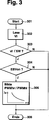
Die
Die
Neben dem in der
Unterschreitet jedoch die Fahrzeuggeschwindigkeit V1 den Schwellwert SW, so wird im Schritt
Wird im Schritt
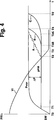
Die
Zum Zeitpunkt T0 betätigt der Fahrer das Bremspedal, wodurch zunächst in gleicher Weise Bremsdruck in die Vorder- und Hinterräder eingespeist wird. Zum Zeitpunkt T1 wird eine Druckbegrenzung an den Hinterradbremsen eingeleitet (Schritt
Wie in der
Weiterhin kann ein zu langes Halten der Differenz ΔP zu folgendem Verhalten führen:
Der Fahrer, der das Fahrzeug nach einem Bremsvorgang mit noch betätigtem Bremspedal abstellt (Zündung aus), spürt ein unangenehmes und überraschendes Nachgeben des Bremspedals, wenn die Einlaßventile durch die abgestellte Strom- bzw. Spannungszufuhr den Druckausgleich mehr oder weniger abrupt einleiten.Furthermore, keeping the difference ΔP too long may lead to the following behavior:
The driver, who turns off the vehicle after a braking operation with the brake pedal still depressed (ignition off), feels an unpleasant and surprising yielding of the brake pedal when the intake valves more or less abruptly initiate the pressure equalization by the parked power supply or voltage.
Aus diesen Gründen wird, wie in der
Wie in der eingangs erwähnten
Die Angleichung des Bremsdrucks wird erfindungsgemäß zum Zeitpunkt T3 begonnen, wobei dieser Zeitpunkt dadurch vorgegeben wird, dass die Fahrzeuglängsgeschwindigkeit V1 einen niedrigen Schwellwert SW (z. B. 3 km/h) unterschreitet (Schritt
Zum Zeitpunkt T3 wird nun erfindungsgemäß nicht durch eine Druckaufbaupulsreihe (Verlauf A) oder gar durch ein schlagartiges Öffnen der Ventile
In
Der Verbraucher
Des weiteren ist eine Steuereinheit
Ausgehend von den erfassten Signalen der Drehzahlsensoren
In
In
Befindet sich das Schaltmittel
Wird die Spule mit einer ausreichenden Spannung beaufschlagt, so wird die Magnetkraft FM größer als die Summe aus Federkraft und Hydraulikkraft. Dies bewirkt, dass die Feder
Um zu erreichen, dass mit einem solchen Ventil ein langsamer und kontinuierlicher Druckangleich stattfindet, wird wie folgt vorgegangen:
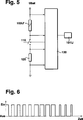
Durch Pulsweitenmodulation des Ansteuersignals PWMij (
By pulse width modulation of the drive signal PWM ij (
Dies hat zur Folge, dass der Druck gegen den das Ventil in seiner geschlossenen Stellung verbleiben kann, langsam absinkt. Das heißt, das Ventil beginnt zu öffnen.This has the consequence that the pressure against which the valve can remain in its closed position, slowly drops. That is, the valve starts to open.
Im Kräftegleichgewicht stehen die öffnende Hydraulikkraft FH, die Federkraft FF und die schließende Magnetkraft FM im Gleichgewicht. Damit ist die Geschwindigkeit des Druckabbaus einstellbar. In
Zum Öffnen des Magnetventils wird das Tastverhältnis von einem Ausgangswert, der erforderlich ist, um das Magnetventil in seinem geschlossenen Zustand zu halten, mit einer vorgebbaren Funktion (z. B. rampenförmig) über der Zeit t auf Null zurückgenommen. Dies hat zur Folge, dass die effektiv am Magnetventil anliegende Spannung Ueff beziehungsweise der Strom Iv ebenfalls über der Zeit entsprechend (z. B. rampenförmig) abnimmt. Entsprechendes gilt für den Druck Pvor, bei dem das Magnetventil noch in seiner geschlossenen Stellung bleibt. Erreicht dieser Druck den tatsächlich herrschenden Wert des Vordrucks, so hebt die Ventilnadel langsam ab und gibt den Fluß der Hydraulikflüssigkeit langsam frei. Durch weitere Verringerung des Tastverhältnisses hebt die Ventilnadel
Bei der erfindungsgemäßen pulsweitenmodulierten Ansteuerung wird die effektive Spannung Ueff beziehungsweise der Strom Iv über der Zeit derart variiert, dass sich der Ventilanker
Der Zeitpunkt T3B oder T3C (
Claims (10)
Priority Applications (6)
| Application Number | Priority Date | Filing Date | Title |
|---|---|---|---|
| DE19653230A DE19653230B4 (en) | 1996-12-20 | 1996-12-20 | Method and device for controlling the brake system of a vehicle |
| US08/988,875 US6019442A (en) | 1996-12-20 | 1997-12-11 | Method and device for controlling the braking system in a vehicle |
| FR9715848A FR2757468B1 (en) | 1996-12-20 | 1997-12-15 | METHOD AND DEVICE FOR CONTROLLING THE BRAKING SYSTEM OF A VEHICLE |
| JP34650597A JP4608035B2 (en) | 1996-12-20 | 1997-12-16 | Control method and apparatus for automobile brake device |
| GB9726627A GB2320540B (en) | 1996-12-20 | 1997-12-16 | Method and device for controlling the braking system of a vehicle |
| JP2008329821A JP2009062048A (en) | 1996-12-20 | 2008-12-25 | Method and device for controlling automobile brake system |
Applications Claiming Priority (1)
| Application Number | Priority Date | Filing Date | Title |
|---|---|---|---|
| DE19653230A DE19653230B4 (en) | 1996-12-20 | 1996-12-20 | Method and device for controlling the brake system of a vehicle |
Publications (2)
| Publication Number | Publication Date |
|---|---|
| DE19653230A1 DE19653230A1 (en) | 1998-06-25 |
| DE19653230B4 true DE19653230B4 (en) | 2012-03-15 |
Family
ID=7815485
Family Applications (1)
| Application Number | Title | Priority Date | Filing Date |
|---|---|---|---|
| DE19653230A Expired - Lifetime DE19653230B4 (en) | 1996-12-20 | 1996-12-20 | Method and device for controlling the brake system of a vehicle |
Country Status (5)
| Country | Link |
|---|---|
| US (1) | US6019442A (en) |
| JP (2) | JP4608035B2 (en) |
| DE (1) | DE19653230B4 (en) |
| FR (1) | FR2757468B1 (en) |
| GB (1) | GB2320540B (en) |
Families Citing this family (12)
| Publication number | Priority date | Publication date | Assignee | Title |
|---|---|---|---|---|
| DE19941482B4 (en) | 1998-09-30 | 2017-11-09 | Robert Bosch Gmbh | Apparatus and method for preventing the backward rolling of a vehicle on a slope |
| JP4263298B2 (en) * | 1999-02-24 | 2009-05-13 | 富士重工業株式会社 | Automatic brake control device for vehicle |
| DE19919841A1 (en) * | 1999-04-30 | 2000-11-02 | Continental Teves Ag & Co Ohg | Method for pressure modulation of brake pressures |
| JP2001171502A (en) | 1999-12-16 | 2001-06-26 | Toyota Motor Corp | Braking control device for vehicle |
| DE10249341A1 (en) * | 2002-10-23 | 2004-05-06 | Zf Friedrichshafen Ag | Hydraulic or pneumatic pressure regulation system forming part of the transmission system in truck or bus has pulse-width operated electro-magnetic valve |
| JP4677977B2 (en) * | 2006-12-06 | 2011-04-27 | トヨタ自動車株式会社 | Brake device for a vehicle in which the distribution ratio between front and rear wheels is controlled according to the braking speed |
| DE102007010942A1 (en) * | 2007-03-07 | 2008-09-11 | Zf Friedrichshafen Ag | Method for pressure control of a switching element |
| US9248815B2 (en) | 2012-12-07 | 2016-02-02 | Robert Bosch Gmbh | System and method for emergency braking |
| DE102017003784A1 (en) * | 2017-04-20 | 2018-10-25 | Wabco Gmbh | Method for teaching switching parameters of a magnetic control valve in a brake system of a vehicle and brake system |
| KR102510867B1 (en) * | 2018-01-31 | 2023-03-16 | 현대두산인프라코어 주식회사 | Brake contorl apparatus and brake control method for construction machinery |
| JP7107716B2 (en) * | 2018-03-27 | 2022-07-27 | 日立Astemo株式会社 | Vehicle control device and vehicle |
| US20210237699A1 (en) * | 2020-02-05 | 2021-08-05 | Ford Global Technologies, Llc | Alternating braking method for smooth stopping from adaptive cruise control |
Citations (7)
| Publication number | Priority date | Publication date | Assignee | Title |
|---|---|---|---|---|
| DE3138647A1 (en) * | 1981-09-29 | 1983-04-14 | Dr.Ing.H.C. F. Porsche Ag, 7000 Stuttgart | "CONTROL DEVICE FOR SOLENOID VALVES" |
| DE4112388A1 (en) * | 1991-04-16 | 1992-10-22 | Bosch Gmbh Robert | BRAKE PRESSURE CONTROL SYSTEM FOR A VEHICLE |
| DE4141354A1 (en) * | 1991-12-14 | 1993-06-17 | Teves Gmbh Alfred | Pressure modulator for vehicle braking circuit - uses pressure drop valve regulated by pulse sequence during pressure drop phase |
| DE4236047A1 (en) * | 1992-10-24 | 1994-04-28 | Teves Gmbh Alfred | Brake system with anti-lock and / or traction control |
| DE19510746A1 (en) * | 1995-03-24 | 1996-09-26 | Bosch Gmbh Robert | Method and device for controlling the brake system of a vehicle |
| DE19511152A1 (en) * | 1995-03-27 | 1996-10-02 | Bosch Gmbh Robert | Method and device for controlling the brake system of a vehicle |
| DE19620037A1 (en) * | 1996-05-17 | 1997-11-20 | Bosch Gmbh Robert | Method and device for controlling a solenoid valve |
Family Cites Families (11)
| Publication number | Priority date | Publication date | Assignee | Title |
|---|---|---|---|---|
| DE3301948A1 (en) * | 1983-01-21 | 1984-07-26 | Alfred Teves Gmbh, 6000 Frankfurt | METHOD AND DEVICE FOR CONTROLLING THE BRAKING DISTRIBUTION |
| JPH01132448A (en) * | 1987-11-19 | 1989-05-24 | Akebono Brake Ind Co Ltd | Control device for antiskid |
| JPH02128951A (en) * | 1988-11-10 | 1990-05-17 | Nippon Denso Co Ltd | Brake device |
| DE3901923A1 (en) * | 1989-01-24 | 1990-09-13 | Bosch Gmbh Robert | ELECTRONICALLY CONTROLLED BRAKE POWER DISTRIBUTOR |
| US5547264A (en) * | 1992-11-04 | 1996-08-20 | Aisin Seiki Kabushiki Kaisha | Braking force distribution control system |
| EP0644093B1 (en) * | 1993-09-22 | 2002-12-11 | Aisin Seiki Kabushiki Kaisha | Apparatus for controlling brake pressure to wheels |
| JP3301183B2 (en) * | 1993-11-24 | 2002-07-15 | 日産自動車株式会社 | Driving force distribution control device between front and rear wheels of vehicle |
| JP3141655B2 (en) * | 1993-11-24 | 2001-03-05 | トヨタ自動車株式会社 | Brake fluid pressure control device |
| JP3869028B2 (en) * | 1995-04-28 | 2007-01-17 | 日産自動車株式会社 | Brake hydraulic pressure control device |
| US5540488A (en) * | 1995-05-11 | 1996-07-30 | Aisin Seiki Kabushiki Kaisha | Hydraulic braking system having an auxiliary pressure source |
| JP3497304B2 (en) * | 1995-11-17 | 2004-02-16 | 本田技研工業株式会社 | Vehicle braking force control device |
-
1996
- 1996-12-20 DE DE19653230A patent/DE19653230B4/en not_active Expired - Lifetime
-
1997
- 1997-12-11 US US08/988,875 patent/US6019442A/en not_active Expired - Lifetime
- 1997-12-15 FR FR9715848A patent/FR2757468B1/en not_active Expired - Fee Related
- 1997-12-16 JP JP34650597A patent/JP4608035B2/en not_active Expired - Fee Related
- 1997-12-16 GB GB9726627A patent/GB2320540B/en not_active Expired - Fee Related
-
2008
- 2008-12-25 JP JP2008329821A patent/JP2009062048A/en active Pending
Patent Citations (9)
| Publication number | Priority date | Publication date | Assignee | Title |
|---|---|---|---|---|
| DE3138647A1 (en) * | 1981-09-29 | 1983-04-14 | Dr.Ing.H.C. F. Porsche Ag, 7000 Stuttgart | "CONTROL DEVICE FOR SOLENOID VALVES" |
| DE4112388A1 (en) * | 1991-04-16 | 1992-10-22 | Bosch Gmbh Robert | BRAKE PRESSURE CONTROL SYSTEM FOR A VEHICLE |
| US5281012A (en) * | 1991-04-16 | 1994-01-25 | Robert Bosch Gmbh | Apparatus for distribution of brake force between front and rear axles |
| EP0509237B1 (en) * | 1991-04-16 | 1995-12-20 | Robert Bosch Gmbh | Brake pressure controlling apparatus |
| DE4141354A1 (en) * | 1991-12-14 | 1993-06-17 | Teves Gmbh Alfred | Pressure modulator for vehicle braking circuit - uses pressure drop valve regulated by pulse sequence during pressure drop phase |
| DE4236047A1 (en) * | 1992-10-24 | 1994-04-28 | Teves Gmbh Alfred | Brake system with anti-lock and / or traction control |
| DE19510746A1 (en) * | 1995-03-24 | 1996-09-26 | Bosch Gmbh Robert | Method and device for controlling the brake system of a vehicle |
| DE19511152A1 (en) * | 1995-03-27 | 1996-10-02 | Bosch Gmbh Robert | Method and device for controlling the brake system of a vehicle |
| DE19620037A1 (en) * | 1996-05-17 | 1997-11-20 | Bosch Gmbh Robert | Method and device for controlling a solenoid valve |
Also Published As
| Publication number | Publication date |
|---|---|
| JPH10181556A (en) | 1998-07-07 |
| FR2757468A1 (en) | 1998-06-26 |
| GB2320540B (en) | 1999-03-10 |
| JP4608035B2 (en) | 2011-01-05 |
| GB9726627D0 (en) | 1998-02-18 |
| JP2009062048A (en) | 2009-03-26 |
| FR2757468B1 (en) | 2003-04-11 |
| US6019442A (en) | 2000-02-01 |
| DE19653230A1 (en) | 1998-06-25 |
| GB2320540A (en) | 1998-06-24 |
Similar Documents
| Publication | Publication Date | Title |
|---|---|---|
| EP2822825B1 (en) | Method for operating a brake system, and brake system | |
| DE4338066C1 (en) | Method for performing an automatic braking process for motor vehicles with an anti-lock braking system | |
| EP1890921B1 (en) | Pressure-controlled hydraulic brake system for a land craft | |
| DE102016013054A1 (en) | Method for adjusting brake pressures of a vehicle, brake system for carrying out the method and vehicle | |
| DE19653230B4 (en) | Method and device for controlling the brake system of a vehicle | |
| DE102008042534A1 (en) | Anti-lock control device and automatic brake control device | |
| DE2757911A1 (en) | BLOCK PROTECTION CONTROL DEVICE | |
| EP3025919A1 (en) | Method for controlling a pneumatic braking system and such a pneumatic braking system for a vehicle | |
| EP3354528B1 (en) | Method for adjusting brake pressures of a motor vehicle by controlling a pressure control valve, brake system for carrying out the method and motor vehicle | |
| DE3923175C2 (en) | Anti-lock braking system for a motor vehicle | |
| DE19528697A1 (en) | Method and device for determining a pressure variable | |
| DE19920096B4 (en) | Device for brake light control | |
| DE19914400A1 (en) | Method and device for compensating the storage pressure in an electro-hydraulic brake system | |
| DE102015015922A1 (en) | Method for adjusting brake pressures on pneumatically actuated wheel brakes of a vehicle, brake system for carrying out the method and vehicle | |
| EP2493733A1 (en) | Method for actuating a high pressure control valve in a hydraulic motor vehicle braking system | |
| EP0163774A2 (en) | Pressure operated vehicle brake installation | |
| DE19547111A1 (en) | Traction control via vehicle braking system | |
| DE10034873B4 (en) | Method and brake system for controlling the braking process in a motor vehicle | |
| WO1997043152A2 (en) | Hydraulic vehicle braking system | |
| DE19981604B4 (en) | Method for operating a brake assist system | |
| EP0786389A2 (en) | Procedure for rebuilding the pressure in a vehicle with an anti-lock system | |
| DE19638196B4 (en) | Device for monitoring a brake system | |
| EP1118517B1 (en) | Vehicle brake system | |
| DE10237463B4 (en) | Method for influencing a hydraulic brake system | |
| DE102005023364A1 (en) | Method for control of intensity of braking action, in particular on inclined surface, comprises integration of information about inclination level |
Legal Events
| Date | Code | Title | Description |
|---|---|---|---|
| 8110 | Request for examination paragraph 44 | ||
| 8125 | Change of the main classification |
Ipc: B60T 826 |
|
| R016 | Response to examination communication | ||
| R016 | Response to examination communication | ||
| R018 | Grant decision by examination section/examining division | ||
| R020 | Patent grant now final |
Effective date: 20120616 |
|
| R071 | Expiry of right |