EP3736216A1 - Passenger suite with table mechanism with vertical, translational and rotational adjustment - Google Patents
Passenger suite with table mechanism with vertical, translational and rotational adjustment Download PDFInfo
- Publication number
- EP3736216A1 EP3736216A1 EP19216028.1A EP19216028A EP3736216A1 EP 3736216 A1 EP3736216 A1 EP 3736216A1 EP 19216028 A EP19216028 A EP 19216028A EP 3736216 A1 EP3736216 A1 EP 3736216A1
- Authority
- EP
- European Patent Office
- Prior art keywords
- support column
- assembly according
- rail
- adjustable
- panel
- Prior art date
- Legal status (The legal status is an assumption and is not a legal conclusion. Google has not performed a legal analysis and makes no representation as to the accuracy of the status listed.)
- Granted
Links
Images



Classifications
-
- B—PERFORMING OPERATIONS; TRANSPORTING
- B64—AIRCRAFT; AVIATION; COSMONAUTICS
- B64D—EQUIPMENT FOR FITTING IN OR TO AIRCRAFT; FLIGHT SUITS; PARACHUTES; ARRANGEMENT OR MOUNTING OF POWER PLANTS OR PROPULSION TRANSMISSIONS IN AIRCRAFT
- B64D11/00—Passenger or crew accommodation; Flight-deck installations not otherwise provided for
- B64D11/06—Arrangements of seats, or adaptations or details specially adapted for aircraft seats
- B64D11/0638—Arrangements of seats, or adaptations or details specially adapted for aircraft seats with foldable tables, trays or cup holders
-
- B—PERFORMING OPERATIONS; TRANSPORTING
- B64—AIRCRAFT; AVIATION; COSMONAUTICS
- B64D—EQUIPMENT FOR FITTING IN OR TO AIRCRAFT; FLIGHT SUITS; PARACHUTES; ARRANGEMENT OR MOUNTING OF POWER PLANTS OR PROPULSION TRANSMISSIONS IN AIRCRAFT
- B64D11/00—Passenger or crew accommodation; Flight-deck installations not otherwise provided for
- B64D11/06—Arrangements of seats, or adaptations or details specially adapted for aircraft seats
- B64D11/0602—Seat modules, i.e. seat systems including furniture separate from the seat itself
- B64D11/0605—Seat modules, i.e. seat systems including furniture separate from the seat itself including tables or desks
-
- B—PERFORMING OPERATIONS; TRANSPORTING
- B60—VEHICLES IN GENERAL
- B60N—SEATS SPECIALLY ADAPTED FOR VEHICLES; VEHICLE PASSENGER ACCOMMODATION NOT OTHERWISE PROVIDED FOR
- B60N3/00—Arrangements or adaptations of other passenger fittings, not otherwise provided for
- B60N3/001—Arrangements or adaptations of other passenger fittings, not otherwise provided for of tables or trays
-
- B—PERFORMING OPERATIONS; TRANSPORTING
- B64—AIRCRAFT; AVIATION; COSMONAUTICS
- B64D—EQUIPMENT FOR FITTING IN OR TO AIRCRAFT; FLIGHT SUITS; PARACHUTES; ARRANGEMENT OR MOUNTING OF POWER PLANTS OR PROPULSION TRANSMISSIONS IN AIRCRAFT
- B64D11/00—Passenger or crew accommodation; Flight-deck installations not otherwise provided for
- B64D11/06—Arrangements of seats, or adaptations or details specially adapted for aircraft seats
- B64D11/0602—Seat modules, i.e. seat systems including furniture separate from the seat itself
- B64D11/0604—Seat modules, i.e. seat systems including furniture separate from the seat itself including a bed, e.g. cocoon type passenger seat modules
-
- B—PERFORMING OPERATIONS; TRANSPORTING
- B64—AIRCRAFT; AVIATION; COSMONAUTICS
- B64D—EQUIPMENT FOR FITTING IN OR TO AIRCRAFT; FLIGHT SUITS; PARACHUTES; ARRANGEMENT OR MOUNTING OF POWER PLANTS OR PROPULSION TRANSMISSIONS IN AIRCRAFT
- B64D11/00—Passenger or crew accommodation; Flight-deck installations not otherwise provided for
- B64D11/06—Arrangements of seats, or adaptations or details specially adapted for aircraft seats
- B64D11/0606—Arrangements of seats, or adaptations or details specially adapted for aircraft seats with privacy shells, screens, separators or the like
Definitions
- Airline operators offer different passenger seating classes with varying levels of amenities at varying ticket costs to fit a variety of budgets and traveler preferences.
- Conventional economy seating classes typically include closely spaced rows of seats for economic and space efficiency.
- Business and first-class seating classes typically include larger living spaces and more generous amenities.
- tray tables may deploy from against the backside of a forward row of seats for use by an aft-positioned row of seats.
- tray tables may be attached to complex hinge mechanisms for vertical and rotational deployment from within an arm rest bay.
- Tray tables may be constructed with separated sections for compact packaging and stowage, wherein the tray table can be deployed and expanded to increase the tabletop size.
- Tabletop sections may be hinged together such that one table section folds against the other. While conventional table mounting arrangements permit deployment and compact stowage, such arrangements provide little or no other adjustability, which may become appreciated or required by customers expecting premium accommodations.
- the present invention provides an adjustable table assembly according to appended claim 1.
- the rail assembly includes a control rail having a first portion extending in the first direction and along which the support column and table are rotatable around a vertical axis defined by the support column, and a second portion extending in the second direction and along which the support column and table are not rotatable around the vertical axis.
- the first portion of the control rail has a first lateral width
- the second portion of the control rail has a second lateral width greater than the first lateral width
- the support column has a radially reduced portion that faces the control rail when the table is in the predetermined stowage orientation.
- At least a portion of the support column has a vertical circular cylindrical wall having a radius, and the radially reduced portion is reduced relative to the radius.
- the radially reduced portion is formed by a chord surface.
- a brake automatically prevents movement of the support column and table along the rail assembly in a braked condition.
- the brake is switched to a freed condition permitting movement of the table along the rail assembly.
- a vertical position of the table is adjustable.
- the table includes a base panel mounted on the support column, and a first folding panel pivotally attached to the base panel, wherein the first folding panel is pivotable relative to the base panel between a folded position and an unfolded position.
- the table includes a second folding panel pivotally attached to the base panel.
- a wall is positioned forward of the passenger seat in the second direction, the base panel has a first linear end to which the first folding panel is pivotally attached, and the predetermined stowage orientation is defined by the first linear end facing the wall.
- the first folding panel in the stowed position of the table, is in the folded position and the first linear end of the base panel faces, and is adjacent, the wall.
- the monument includes a bed.
- the present invention provides an aircraft passenger suite as defined in claim 14.
- the base panel has a first linear end to which the first folding panel is pivotally attached, and wherein the predetermined stowage orientation is defined by the first linear end facing the second direction or first direction.
- the present invention may include one or more or any combination of the above aspects, features and configurations.
- the present invention is generally directed to a passenger suite layout including a table mechanism repositionable within the suite and reconfigurable for different uses.
- the suite generally includes an adjustable seat positioned to one side of a fixed bed.
- the table mechanism is mounted to track or rail assembly along a side of the bed adjacent the seat.
- the table mechanism includes a folding table system (e.g., bifold or trifold) including dampened hinges.
- the table mechanism(s) provide three-degrees of freedom including forward/aft movement (i.e., translational movement), vertical movement, and rotational movement.
- Each motion component may be held in place by a brake or other mechanism.
- brakes in a normal passenger use state all brakes are applied.
- actuators release the brakes to permit movement.
- user force is applied to translate and/or rotate the table top.
- the table illustrated in the drawings is shown as a trifold table 20, having three leaves or panels, as a non-limiting example.
- Other tables such as single panel tables having one leaf, and bifold tables having two leaves or panels, are within the scope of these descriptions. These are all non-limiting examples.
- the table 20 is shown in an aircraft passenger environment, referenced and described below as a passenger suite 70.
- the table as described and illustrated is provided without the features of the suite 70.
- a folding table in an adjustable table assembly can be moved and supported by a support assembly, referenced for example in the following as the support assembly 110, along a fixed rail assembly 104 in other environments with or without the bed 90 and passenger seat 74.
- the drawings illustrate a single table mounted to the rail assembly as a non-limiting example. In some implementations, two tables may be mounted to the same rail assembly for independent movement thereon.
- the illustrated trifold table 20 is mounted upon a support column 126 by which the trifold table can be translated fore and aft by movement along a longitudinal axis 22, and up and down along a vertical axis 24.
- a first longitudinal direction 23 toward a passenger seat is treated as an aft or rearward direction with regard to the aircraft fuselage in which the passenger suite represented in FIG. 1 .
- a second longitudinal direction 25, opposite the first direction 23, is treated as a forward direction.
- the first longitudinal direction 23 may be forward or another direction with respect to an aircraft.
- the trifold table 20 is also rotatable around the vertical axis 24 by a rotation function of the support column. Movements of the trifold table 20 are explained in the following descriptions after descriptions of its folding and unfolding functions.
- the trifold table 20 has three interconnected generally planar rigid panels, two of which hinge or fold to stowed positions.
- a generally planar and rigid first panel, referenced as a central base panel 30, is mounted from below on a support column.
- the base panel 30, in an example implementation, is maintained as generally horizontal.
- the trifold table 20 has a generally planar and rigid second panel, referenced as a close folding panel 40 for its close contact with the base panel 30 in the folded condition of the trifold table 20.
- the close folding panel 40 is pivotally attached to the base panel 30 by hinges 60.
- a generally planar and rigid third panel is referenced as the spaced folding panel 50 for its vertical offset from the base panel 30 in the folded condition ( FIG. 2 ) of the trifold table 20 to accommodate the close folding panel 40 therebetween.
- the top side 31 of the base panel 30, the top side 41 of the close folding panel 40, and the top side 51 of the spaced folding panel 50 are essentially coplanar to serve together as a table top.
- the base panel 30 has a first linear end 32 pivotally attached to a proximal linear end 42 of the close folding panel 40 by first hinges 60.
- the first hinges may be dampened hinges in a particular embodiment as described below.
- a second linear end 34 of the base panel 30 is attached by second hinges 62 to a proximal linear end of the spaced folding panel 50.
- the second hinges 62 accommodate the vertical offset of the spaced folding panel 50 from the base panel 30 in the folded condition of the trifold table 20.
- the close folding panel 40 and spaced folding panel 50 have respective free distal ends 44 and 54 that define the deployed ends of the trifold table 20 in the unfolded condition.
- the close folding panel 40 and spaced folding panel 50 pivot at their attached proximal ends as their free distal ends 44 and 54 travel to their destinations.
- the close folding panel 40 should transition ahead of the spaced folding panel 50 when folding the trifold table 20, keeping the close folding panel 40 closer to the base panel 30 than the spaced folding panel 50, to permit a stacked stable folded condition ( FIGS. 2, 3 ).
- the base panel 30, the close folding panel 40, and the spaced folding panel 50 have generally the same widths W, defining the general width of the table in any folded or unfolded condition. They have generally the same lengths as well, the sum of which approximately defines the length L of the trifold table 20 in the unfolded condition. That they have the same lengths and widths also provides a neat appearing assembly in the stacked folded condition in which exposed ends and sides align without considerable overhangs.
- the base panel 30 is rectangular, having linear first and second sides 36 and 38, which are perpendicular to the linear first and second ends 32 and 34.
- the close folding panel 40 and the spaced folding panel 50 have respective linear first sides 46 and 56 defining, together with the first linear side 36 of the base panel 30, a first linear side 26 of the trifold table 20 in the unfolded condition.
- the respective second sides 48 and 58 are arcuate near the distal ends 44 and 54, such that the corners of the second side 28 of the deployed trifold table 20 are tapered, rounded, or beveled for safety and aesthetic purposes.
- the first hinges 60 by which the close folding panel 40 is attached to the base panel 30, permit them to stack or overlap as they are folded together.
- the first hinges 60 furthermore permit the close folding panel 40 and base panel 30 to align and contact at their attached linear ends 42 and 32 in the unfolded planar condition.
- the first hinges 60 may be biased toward relative positions of the base panel 30 and close folding panel 40 that are intermediate positions between the limits of their relative motion range, which are the planar fully unfolded position ( FIGS. 1 , 5 ) and the stacked fully folded position ( FIGS. 2, 3 ). This slows hinging movement as the limits of their motion range are approached. This also provides lift assistance when a user pivotally raises the close folding panel 40 from either limit of its motion range, which are horizontal and relatively low positions.
- the hinges 60 may also or furthermore be motion-dampening at the limits of their motion range. This provides braking of the pivoting movement of the close folding panel 40 at it approaches the limits of its motion range, reducing clatter noise as the table is folded and unfolded. Dampening may be applied by the hinges 60, against folding toward the fully folded condition when the angle between the top side 31 of the base panel 30 and the top side 41 of the close folding panel 40 is in a range of approximately 30 degrees (30°) to 0 degrees (0°) such that dampening against further folding is applied at 30 degrees (30°) and increases as the fully folded condition is further approached.
- Dampening may also applied by against unfolding toward the planar condition when the angle between the top side 31 and the top side 41 is in a range of approximately 150 degrees (150°) to 180 degrees (180°) such that dampening against further unfolding is applied at 150 degrees (150°) and increases as the planar condition is further approached.
- the second hinges 62 may provide similar beneficial functions, including biasing and motion dampening, at the limits of the motion range of the spaced folding panel 50.
- the first hinges 60 and second hinges 62 provide positive stopping when the planar unfolded condition is reached to provide a firm planar table top.
- the close folding panel 40 and the spaced folding panel 50 are entirely supported by the base panel 30.
- the close folding panel 40 and the spaced folding panel 50 are supported by the base panel 30 and hinges in cantilever fashion.
- the passenger suite 70 in which the trifold table 20 can be deployed includes a first end wall 72 behind a passenger seat 74, and a second end wall 76 forward of the passenger seat 74.
- the passenger-right sidewall 80 of the suite includes a movable door 82 that translates forward or aft from the illustrated closed position to an open position to permit entry and egress of occupants from and to an aisle of the aircraft.
- the passenger-left edges 84 of the end walls 72 and 76 are shown as arcuate to match the contour of an aircraft fuselage and to imply a corresponding passenger-left sidewall of the passenger suite 70.
- a media display screen 86 is shown as mounted on the second end wall 76, represented as the forward end of the passenger suite.
- a longitudinally extending bed 90 is shown from the first end wall 72 to the second end wall 76 along the left side of the passenger suite.
- the support assembly 100 that carries the table 20 includes a carriage 102 ( FIG. 11 ), that is mounted on a stationary rail assembly 104.
- the rail assembly is fixed or stationary relative to a fixed monument, referenced for example, as a bed 90 having a frame 92 along which or to which the rail assembly 104 is fixed.
- the rail assembly 104 includes a longitudinally extending first rail 106 upon which a sled 110 of the carriage is mounted. The sled is attached to a longitudinally spaced pair of rings that slide along the first rail.
- the rail assembly includes a longitudinally extending second rail 112 abutted from below by a distal end of the sled.
- the first rail 106 supports the sled and support assembly 100 and acts as a fulcrum. The moment of the support assembly 100 at the first rail 106 is countered by the second rail 112 and distal end of the sled 110 to maintain the sled as generally horizontal, the support assembly 100 as generally vertical, and the base panel 30 of the trifold table 20 as horizontal.
- the carriage 102 moves longitudinally along the first rail 106 and second rail 112 when a brake 114 is in a freed condition.
- the brake is attached to the sled and selectively engages a longitudinally extending third rail 116 of the rail assembly between the first rail 106 and second rail 112.
- the brake 114 ( FIG. 12 ) is automatically maintained in a braked condition by springs carried by the sled. In the absence of external force on the trifold table, for example by user action, the brake in the braked condition prevents movement of the support column 126 and table 20 along the rail assembly 104 in either longitudinal direction. This maintains the sled 110 and table therewith in any current position on the rail assembly.
- the brake 114 When an external force is applied to the table 20, for example when a user applies fore or aft force upon the table 20, the brake 114 is switched to the freed condition.
- a first linkage 120 coupled to the base panel 30 pivots about a post connected to the sled of the carriage.
- the first linkage thereby moves a second linkage 122 against the otherwise balanced forces of the springs, and the second linkage switches the brake 114 to the freed condition, permitting movement of the trifold table in the direction in which user force is applied.
- the rails 106, 112, 116 are tubular in the illustrated embodiment, for smooth motion of the sled along the rails.
- the table can be moved, for example, in a rearward or aft direction from the forward stowed position of FIG. 2 toward the passenger seat progressively to the deployed position of FIG. 3 .
- the trifold table can be returned forward to the stowed position by a user applying force in a second longitudinal direction 25 opposite the first direction 23.
- This described example, in which the table is moved by user applied force is a non-limiting example.
- movement of the table for example in the fore and aft directions, is motorized.
- the vertical position of the trifold table is adjustable.
- the carriage 102 includes a vertical bracket 124 connected to a side of the sled 110 facing outward from the rails.
- a support column 126 extends upward from the vertical bracket and supports the trifold table.
- An elevating shelf 130 which carries the support column, is mounted on the vertical bracket by way of rollers and is vertically movable along the bracket. By vertical movement of the elevating shelf 130, the support column 126 and the trifold table 20 thereon can be adjustably raised and lowered as represented in FIGS. 6 and 7 .
- the elevating shelf is selectively permitted and restricted from vertical movement by a user actuatable elevation locking mechanism.
- the elevation locking mechanism in the illustrated embodiment is a gas cylinder device 132 disposed along the vertical axis 24 and having a lower end connected to a bottom plate of the vertical bracket 124 and an upper end connected to the base panel 30 of the trifold table.
- a locked condition of the gas cylinder device the vertical position of the trifold table relative to the bottom plate of the vertical bracket is fixed, preventing the elevating shelf and trifold table from raising or lowering.
- an unlocked condition of the gas cylinder device the vertical position of the trifold table is permitted to raise and lower by extension and withdrawal of a piston of the gas cylinder, permitting the elevating shelf to raise and lower.
- the elevation locking mechanism is selectively locked and unlocked by actuation of either of two buttons 134, each of which is mounted along the lower side of the base panel 30 near a respective linear side 36 as shown in FIGS. 13 and 14 .
- a user presses either button to unlock the locking mechanism to permit raising and lowering of the trifold table by further lifting or pressing on the table. See FIGS. 6 and 7 , for example, which show the trifold table 20 in a relatively raised vertical position and a relatively lowered vertical position, respectively.
- the elevation locking mechanism may be considered a vertical movement brake, whereas the brake 114 may be considered a horizontal or translational movement brake.
- the lower end of the support column 126 is connected to the elevating shelf 130 by a roller bearing assembly 136 ( FIG. 14 ) to facilitate rotation of the column around the vertical axis 24.
- the roller bearing assembly houses wave washers and friction pads to apply mild resistance against rotational movement. The resistance is overcome by external force such as user action applying torque to rotate the trifold table to a desired orientation, but the resistance prevents unwanted spinning or swaying of the table in the absence of external force. See FIGS. 8-10 , in which the trifold table 20 is shown in several rotational positions in the unfolded condition.
- the trifold table 20 is permitted to rotate in deployed positions of the passenger suite 70 where the dimensions of the table in the unfolded condition ( FIGS. 8-10 ) can be accommodated. Furthermore, for compact stowing of the trifold table at the forward second end wall 76 of the passenger suite 70 ( FIG. 2 ), a particular linear end 32 of the base panel must face the wall 76, and be oriented perpendicular relative to the longitudinal axis 22, in order for the trifold table 20 to be permitted to approach the wall 76 by the rail assembly. This orientation defines a predetermined stowage orientation. Note also that the fully stowed position of FIG. 2 can only be reached when at least the close folding panel 40 is in a folded condition relative to the base panel 30 with the first linear end 32 of the base panel 30 facing and adjacent the wall 76.
- a control feature automatically prevents or permits the support column 126 and trifold table 20 to rotate according to the position of the support column along the longitudinal axis 22; and automatically permits the support column 126 and trifold table 20 to move longitudinally forward beyond a predetermined position only when the table is in the predetermined stowage orientation, in which the first linear end 32 faces the wall 76.
- These control features are facilitated by a stationary control rail 142 that automatically engages the support column 126 according to the longitudinal position and rotational orientation of the column 126.
- the stationary control rail 142 which may be considered part of the aforedescribed rail assembly 104, is connected to a frame of the bed 90 and extends parallel to the longitudinal axis 22.
- the control rail 142 has a rearward first portion 144 ( FIG. 15 ), the length of which defines a range of longitudinal positions of the trifold table 30 in which rotation is permitted.
- the control rail 142 has a forward second portion 146, the length of which defines the range of longitudinal positions of the trifold table 30 in which rotation is prevented.
- FIG. 15 shows the carriage and support column from below in two positions (X1, X2) along the control rail 142 to illustrate rotational unlocking and locking at positions along the rearward first portion 144 and forward second portion 146 respectively, which are shown in part at least.
- the control rail 142 has a first lateral side 150 facing the support column and a second lateral side 152 facing oppositely.
- the second lateral side 152 is linear.
- the first lateral side 150 is linear along the first portion 144 of the control rail; and the first lateral side is linear along the second portion 146 as well.
- the two linear portions 144 and 146 of the first side 150 are offset, such that a lateral width W1 of the first portion 144 of the control rail 142 is lesser than a lateral width W2 of the second portion 146.
- the width of the control rail 142 transitions from W1 to W2 at a junction 145 of the first portion 144, which extends in the first longitudinal direction 23 from the junction 145, and the second portion 146, which extends in the second longitudinal direction 25 from the junction.
- the support column 126 includes a radially reduced portion 154 ( FIG. 14 ) to accommodate the greater lateral width W2 of the second portion 146 of the control rail 142.
- At least a portion of the support column 126 has a vertical circular cylindrical wall 128 having a radius R ( FIG. 15 ), and the radially reduced portion 154 is formed by a chord surface.
- a chord of a circle is a straight line segment whose endpoints both lie on the circle.
- the support column 126 can travel along the rail assembly 104 forward from the first portion 144 of the control rail 142 only in the predetermined stowage orientation, in which the radially reduced portion 154 faces the control rail 142 to accommodate the greater width W2.
- the reduced portion 154 extends vertically to accommodate vertical positions of the trifold table.
- the support column includes a pair of rollers 156 extending vertically at vertical edges of the reduced portion to guide or ease transition, for example to assist a user in finding the predetermined stowage orientation, in which the first linear end 32 faces the wall 76, to permit forward movement along the second portion 146 of the control rail 142.
- the support column 126 and trifold table 20 are positioned adjacent the first portion 144, for example as represented at the first position X1 in FIG. 15 , the support column and rollers 156 are disengaged from the control rail 142, permitting rotation of the support column and trifold table 20.
- the support column 126 and trifold table 20 are positioned adjacent the second portion 146, for example as represented at the first position X2 in FIG. 15 , the chord surface of the support column and the rollers 156 are engaged with or are at least in close proximity with the control rail 142, preventing rotation of the support column and trifold table from the predetermined stowage orientation.
- the reduced portion 154 FIG.
- the trifold table is not in the predetermined stowage orientation, and the support column 126 accordingly cannot travel forward from the first portion 144, because the support column 126, by hitting the junction 145 ( FIG. 15 ), cannot travel forward to positions adjacent the second portion 146.
- the support column 126 can travel forward from the junction 145 to positions adjacent the second portion 146 of the control rail 142, for example to the stowed position of FIG. 2 , while being prevented from rotating from the predetermined stowage position.
Landscapes
- Engineering & Computer Science (AREA)
- Aviation & Aerospace Engineering (AREA)
- Transportation (AREA)
- Mechanical Engineering (AREA)
- Tables And Desks Characterized By Structural Shape (AREA)
- Seats For Vehicles (AREA)
Abstract
Description
- Airline operators offer different passenger seating classes with varying levels of amenities at varying ticket costs to fit a variety of budgets and traveler preferences. Conventional economy seating classes typically include closely spaced rows of seats for economic and space efficiency. Business and first-class seating classes typically include larger living spaces and more generous amenities.
- One amenity found in many types of seating classes is a tray table, sometimes referred to as a meal table. In economy seating classes, tray tables may deploy from against the backside of a forward row of seats for use by an aft-positioned row of seats. In a first row of seats, tray tables may be attached to complex hinge mechanisms for vertical and rotational deployment from within an arm rest bay. Tray tables may be constructed with separated sections for compact packaging and stowage, wherein the tray table can be deployed and expanded to increase the tabletop size. Tabletop sections may be hinged together such that one table section folds against the other. While conventional table mounting arrangements permit deployment and compact stowage, such arrangements provide little or no other adjustability, which may become appreciated or required by customers expecting premium accommodations.
- Accordingly, improvements are needed in table assemblies and passenger suites.
- To achieve the foregoing , according to a first aspect, the present invention provides an adjustable table assembly according to appended claim 1.
- In some embodiments, the rail assembly includes a control rail having a first portion extending in the first direction and along which the support column and table are rotatable around a vertical axis defined by the support column, and a second portion extending in the second direction and along which the support column and table are not rotatable around the vertical axis.
- In some embodiments, the first portion of the control rail has a first lateral width, the second portion of the control rail has a second lateral width greater than the first lateral width, and the support column has a radially reduced portion that faces the control rail when the table is in the predetermined stowage orientation.
- In some embodiments, at least a portion of the support column has a vertical circular cylindrical wall having a radius, and the radially reduced portion is reduced relative to the radius.
- In some embodiments, the radially reduced portion is formed by a chord surface.
- In some embodiments, a brake automatically prevents movement of the support column and table along the rail assembly in a braked condition. When a user applies force in the first direction or second direction, the brake is switched to a freed condition permitting movement of the table along the rail assembly.
- In some embodiments, a vertical position of the table is adjustable.
- In some embodiments, the table includes a base panel mounted on the support column, and a first folding panel pivotally attached to the base panel, wherein the first folding panel is pivotable relative to the base panel between a folded position and an unfolded position.
- In some embodiments, the table includes a second folding panel pivotally attached to the base panel.
- In some embodiments, a wall is positioned forward of the passenger seat in the second direction, the base panel has a first linear end to which the first folding panel is pivotally attached, and the predetermined stowage orientation is defined by the first linear end facing the wall.
- In some embodiments, in the stowed position of the table, the first folding panel is in the folded position and the first linear end of the base panel faces, and is adjacent, the wall.
- In some embodiments, the monument includes a bed.
- According to a second aspect, the present invention provides an aircraft passenger suite as defined in
claim 14. - In some embodiments, the base panel has a first linear end to which the first folding panel is pivotally attached, and wherein the predetermined stowage orientation is defined by the first linear end facing the second direction or first direction.
- The present invention may include one or more or any combination of the above aspects, features and configurations.
- The present invention may be better understood when consideration is given to the following detailed description thereof. Such description refers to the included drawings, which are not necessarily to scale, and in which some features may be exaggerated, and some features may be omitted or may be represented schematically in the interest of clarity. Like reference numbers in the drawings may represent and refer to the same or similar element, feature, or function. In the drawings:
-
FIG. 1 is a perspective view of an aircraft passenger suite, according to the present invention, shown with a trifold table thereof in a deployed position and an unfolded condition; -
FIG. 2 is a perspective view of the passenger suite ofFIG. 1 , shown with the trifold table in a stowed position and a folded condition; -
FIG. 3 is a perspective view as inFIG. 2 , with the trifold table folded in a deployed position; -
FIG. 4 is a perspective view as inFIG. 3 , shown with the trifold table partially unfolded in the deployed position; -
FIG. 5 is an overhead enlarged view of the trifold table ofFIG. 1 in the unfolded condition; -
FIG. 6 is a perspective view of the trifold table ofFIG. 1 , in a raised vertical position thereof; -
FIG. 7 is a perspective view as inFIG. 6 , showing the trifold table in a lowered vertical position thereof; -
FIG. 8 is an overhead view of the passenger suite ofFIG. 1 , showing the trifold table in use in the orientation ofFIG. 1 ; -
FIG. 9 is a perspective view of the trifold table in a rotated position relative to that ofFIG. 8 ; -
FIG. 10 is a perspective view of the trifold table in another rotated position relative to that ofFIG. 8 ; -
FIG. 11 is a perspective view of a portion of the trifold table ofFIG. 1 and a support column and rail assembly; -
FIG. 12 is a bottom view of portions of the support column and rail assembly ofFIG. 11 ; -
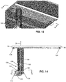
FIG. 13 is a perspective view of a lower side of the trifold table ofFIG. 1 ; -
FIG. 14 is a forward directed cross section view, taken at the lines 14-14 inFIG. 13 ; and -
FIG. 15 is a downward directed cross section view, taken at the lines 15-15 inFIG. 14 , showing a lower portion of the support column at two longitudinal positions to illustrate rotational locking and unlocking. - The description set forth below in connection with the appended drawings is intended to be a description of various, illustrative embodiments of the present invention. Specific features and functionalities are described in connection with each illustrative embodiment; however, it will be apparent to those skilled in the art that the disclosed embodiments may be practiced without each of those specific features and functionalities. The aspects, features and functions described below in connection with one embodiment are intended to be applicable to the other embodiments described below except where expressly stated or where an aspect, feature or function is incompatible with an embodiment.
- The present invention is generally directed to a passenger suite layout including a table mechanism repositionable within the suite and reconfigurable for different uses. The suite generally includes an adjustable seat positioned to one side of a fixed bed. The table mechanism is mounted to track or rail assembly along a side of the bed adjacent the seat. The table mechanism includes a folding table system (e.g., bifold or trifold) including dampened hinges. The table mechanism(s) provide three-degrees of freedom including forward/aft movement (i.e., translational movement), vertical movement, and rotational movement. Each motion component may be held in place by a brake or other mechanism. In some embodiments, in a normal passenger use state all brakes are applied. In some embodiments, actuators release the brakes to permit movement. In some embodiments, user force is applied to translate and/or rotate the table top.
- The table illustrated in the drawings is shown as a trifold table 20, having three leaves or panels, as a non-limiting example. Other tables, such as single panel tables having one leaf, and bifold tables having two leaves or panels, are within the scope of these descriptions. These are all non-limiting examples. The table 20 is shown in an aircraft passenger environment, referenced and described below as a
passenger suite 70. In some implementations, the table as described and illustrated is provided without the features of thesuite 70. For example, a folding table in an adjustable table assembly can be moved and supported by a support assembly, referenced for example in the following as thesupport assembly 110, along afixed rail assembly 104 in other environments with or without thebed 90 andpassenger seat 74. The drawings illustrate a single table mounted to the rail assembly as a non-limiting example. In some implementations, two tables may be mounted to the same rail assembly for independent movement thereon. - The illustrated trifold table 20 is mounted upon a
support column 126 by which the trifold table can be translated fore and aft by movement along alongitudinal axis 22, and up and down along avertical axis 24. For convenient convention, a firstlongitudinal direction 23 toward a passenger seat is treated as an aft or rearward direction with regard to the aircraft fuselage in which the passenger suite represented inFIG. 1 . A secondlongitudinal direction 25, opposite thefirst direction 23, is treated as a forward direction. In other implementations, the firstlongitudinal direction 23 may be forward or another direction with respect to an aircraft. The trifold table 20 is also rotatable around thevertical axis 24 by a rotation function of the support column. Movements of the trifold table 20 are explained in the following descriptions after descriptions of its folding and unfolding functions. - The trifold table 20 has three interconnected generally planar rigid panels, two of which hinge or fold to stowed positions. A generally planar and rigid first panel, referenced as a
central base panel 30, is mounted from below on a support column. Thebase panel 30, in an example implementation, is maintained as generally horizontal. - The trifold table 20 has a generally planar and rigid second panel, referenced as a
close folding panel 40 for its close contact with thebase panel 30 in the folded condition of the trifold table 20. Theclose folding panel 40 is pivotally attached to thebase panel 30 by hinges 60. A generally planar and rigid third panel is referenced as the spacedfolding panel 50 for its vertical offset from thebase panel 30 in the folded condition (FIG. 2 ) of the trifold table 20 to accommodate theclose folding panel 40 therebetween. - In the unfolded and flat condition of the trifold table 20 as illustrated in
FIG. 5 , thetop side 31 of thebase panel 30, thetop side 41 of theclose folding panel 40, and thetop side 51 of the spacedfolding panel 50, are essentially coplanar to serve together as a table top. Thebase panel 30 has a firstlinear end 32 pivotally attached to a proximallinear end 42 of theclose folding panel 40 by first hinges 60. The first hinges may be dampened hinges in a particular embodiment as described below. A secondlinear end 34 of thebase panel 30 is attached bysecond hinges 62 to a proximal linear end of the spacedfolding panel 50. The second hinges 62 accommodate the vertical offset of the spacedfolding panel 50 from thebase panel 30 in the folded condition of the trifold table 20. - The
close folding panel 40 and spaced foldingpanel 50 have respective free distal ends 44 and 54 that define the deployed ends of the trifold table 20 in the unfolded condition. As the trifold table 20 transitions from the folded condition through the partially folded condition to the unfolded condition, theclose folding panel 40 and spaced foldingpanel 50 pivot at their attached proximal ends as their free distal ends 44 and 54 travel to their destinations. Theclose folding panel 40 should transition ahead of the spacedfolding panel 50 when folding the trifold table 20, keeping theclose folding panel 40 closer to thebase panel 30 than the spacedfolding panel 50, to permit a stacked stable folded condition (FIGS. 2, 3 ). - The
base panel 30, theclose folding panel 40, and the spacedfolding panel 50 have generally the same widths W, defining the general width of the table in any folded or unfolded condition. They have generally the same lengths as well, the sum of which approximately defines the length L of the trifold table 20 in the unfolded condition. That they have the same lengths and widths also provides a neat appearing assembly in the stacked folded condition in which exposed ends and sides align without considerable overhangs. - The
base panel 30 is rectangular, having linear first andsecond sides close folding panel 40 and the spacedfolding panel 50 have respective linearfirst sides linear side 36 of thebase panel 30, a first linear side 26 of the trifold table 20 in the unfolded condition. The respectivesecond sides close folding panel 40 and spaced foldingpanel 50, opposite thefirst sides second side 38 of the base panel, define a second side 28 of the trifold table 20. The respectivesecond sides - The first hinges 60, by which the
close folding panel 40 is attached to thebase panel 30, permit them to stack or overlap as they are folded together. The first hinges 60 furthermore permit theclose folding panel 40 andbase panel 30 to align and contact at their attached linear ends 42 and 32 in the unfolded planar condition. The first hinges 60 may be biased toward relative positions of thebase panel 30 andclose folding panel 40 that are intermediate positions between the limits of their relative motion range, which are the planar fully unfolded position (FIGS. 1 ,5 ) and the stacked fully folded position (FIGS. 2, 3 ). This slows hinging movement as the limits of their motion range are approached. This also provides lift assistance when a user pivotally raises theclose folding panel 40 from either limit of its motion range, which are horizontal and relatively low positions. - The hinges 60 may also or furthermore be motion-dampening at the limits of their motion range. This provides braking of the pivoting movement of the
close folding panel 40 at it approaches the limits of its motion range, reducing clatter noise as the table is folded and unfolded. Dampening may be applied by thehinges 60, against folding toward the fully folded condition when the angle between thetop side 31 of thebase panel 30 and thetop side 41 of theclose folding panel 40 is in a range of approximately 30 degrees (30°) to 0 degrees (0°) such that dampening against further folding is applied at 30 degrees (30°) and increases as the fully folded condition is further approached. Dampening may also applied by against unfolding toward the planar condition when the angle between thetop side 31 and thetop side 41 is in a range of approximately 150 degrees (150°) to 180 degrees (180°) such that dampening against further unfolding is applied at 150 degrees (150°) and increases as the planar condition is further approached. - The second hinges 62 may provide similar beneficial functions, including biasing and motion dampening, at the limits of the motion range of the spaced
folding panel 50. The first hinges 60 and second hinges 62 provide positive stopping when the planar unfolded condition is reached to provide a firm planar table top. In any position, theclose folding panel 40 and the spacedfolding panel 50 are entirely supported by thebase panel 30. Particularly, theclose folding panel 40 and the spacedfolding panel 50 are supported by thebase panel 30 and hinges in cantilever fashion. - Returning to
FIG. 1 , thepassenger suite 70 in which the trifold table 20 can be deployed includes afirst end wall 72 behind apassenger seat 74, and asecond end wall 76 forward of thepassenger seat 74. The passenger-right sidewall 80 of the suite includes amovable door 82 that translates forward or aft from the illustrated closed position to an open position to permit entry and egress of occupants from and to an aisle of the aircraft. The passenger-leftedges 84 of theend walls passenger suite 70. - A
media display screen 86 is shown as mounted on thesecond end wall 76, represented as the forward end of the passenger suite. A longitudinally extendingbed 90 is shown from thefirst end wall 72 to thesecond end wall 76 along the left side of the passenger suite. Thesupport assembly 100 that carries the table 20 includes a carriage 102 (FIG. 11 ), that is mounted on astationary rail assembly 104. The rail assembly is fixed or stationary relative to a fixed monument, referenced for example, as abed 90 having aframe 92 along which or to which therail assembly 104 is fixed. Therail assembly 104 includes a longitudinally extendingfirst rail 106 upon which asled 110 of the carriage is mounted. The sled is attached to a longitudinally spaced pair of rings that slide along the first rail. The rail assembly includes a longitudinally extendingsecond rail 112 abutted from below by a distal end of the sled. Thefirst rail 106 supports the sled andsupport assembly 100 and acts as a fulcrum. The moment of thesupport assembly 100 at thefirst rail 106 is countered by thesecond rail 112 and distal end of thesled 110 to maintain the sled as generally horizontal, thesupport assembly 100 as generally vertical, and thebase panel 30 of the trifold table 20 as horizontal. - The
carriage 102 moves longitudinally along thefirst rail 106 andsecond rail 112 when abrake 114 is in a freed condition. The brake is attached to the sled and selectively engages a longitudinally extendingthird rail 116 of the rail assembly between thefirst rail 106 andsecond rail 112. The brake 114 (FIG. 12 ) is automatically maintained in a braked condition by springs carried by the sled. In the absence of external force on the trifold table, for example by user action, the brake in the braked condition prevents movement of thesupport column 126 and table 20 along therail assembly 104 in either longitudinal direction. This maintains thesled 110 and table therewith in any current position on the rail assembly. When an external force is applied to the table 20, for example when a user applies fore or aft force upon the table 20, thebrake 114 is switched to the freed condition. When a user applies fore or aft force upon the table 20, afirst linkage 120 coupled to thebase panel 30 pivots about a post connected to the sled of the carriage. The first linkage thereby moves asecond linkage 122 against the otherwise balanced forces of the springs, and the second linkage switches thebrake 114 to the freed condition, permitting movement of the trifold table in the direction in which user force is applied. Therails - Thus, by intuitive user action applying force in the first
longitudinal direction 23 upon the trifold table, the table can be moved, for example, in a rearward or aft direction from the forward stowed position ofFIG. 2 toward the passenger seat progressively to the deployed position ofFIG. 3 . The trifold table can be returned forward to the stowed position by a user applying force in a secondlongitudinal direction 25 opposite thefirst direction 23. This described example, in which the table is moved by user applied force, is a non-limiting example. In some implementations, movement of the table, for example in the fore and aft directions, is motorized. - The vertical position of the trifold table is adjustable. The
carriage 102 includes avertical bracket 124 connected to a side of thesled 110 facing outward from the rails. Asupport column 126 extends upward from the vertical bracket and supports the trifold table. An elevatingshelf 130, which carries the support column, is mounted on the vertical bracket by way of rollers and is vertically movable along the bracket. By vertical movement of the elevatingshelf 130, thesupport column 126 and the trifold table 20 thereon can be adjustably raised and lowered as represented inFIGS. 6 and 7 . The elevating shelf is selectively permitted and restricted from vertical movement by a user actuatable elevation locking mechanism. The elevation locking mechanism in the illustrated embodiment is agas cylinder device 132 disposed along thevertical axis 24 and having a lower end connected to a bottom plate of thevertical bracket 124 and an upper end connected to thebase panel 30 of the trifold table. In a locked condition of the gas cylinder device, the vertical position of the trifold table relative to the bottom plate of the vertical bracket is fixed, preventing the elevating shelf and trifold table from raising or lowering. In an unlocked condition of the gas cylinder device, the vertical position of the trifold table is permitted to raise and lower by extension and withdrawal of a piston of the gas cylinder, permitting the elevating shelf to raise and lower. - The elevation locking mechanism is selectively locked and unlocked by actuation of either of two
buttons 134, each of which is mounted along the lower side of thebase panel 30 near a respectivelinear side 36 as shown inFIGS. 13 and 14 . A user presses either button to unlock the locking mechanism to permit raising and lowering of the trifold table by further lifting or pressing on the table. SeeFIGS. 6 and 7 , for example, which show the trifold table 20 in a relatively raised vertical position and a relatively lowered vertical position, respectively. The elevation locking mechanism may be considered a vertical movement brake, whereas thebrake 114 may be considered a horizontal or translational movement brake. - The lower end of the
support column 126 is connected to the elevatingshelf 130 by a roller bearing assembly 136 (FIG. 14 ) to facilitate rotation of the column around thevertical axis 24. The roller bearing assembly houses wave washers and friction pads to apply mild resistance against rotational movement. The resistance is overcome by external force such as user action applying torque to rotate the trifold table to a desired orientation, but the resistance prevents unwanted spinning or swaying of the table in the absence of external force. SeeFIGS. 8-10 , in which the trifold table 20 is shown in several rotational positions in the unfolded condition. - The trifold table 20 is permitted to rotate in deployed positions of the
passenger suite 70 where the dimensions of the table in the unfolded condition (FIGS. 8-10 ) can be accommodated. Furthermore, for compact stowing of the trifold table at the forwardsecond end wall 76 of the passenger suite 70 (FIG. 2 ), a particularlinear end 32 of the base panel must face thewall 76, and be oriented perpendicular relative to thelongitudinal axis 22, in order for the trifold table 20 to be permitted to approach thewall 76 by the rail assembly. This orientation defines a predetermined stowage orientation. Note also that the fully stowed position ofFIG. 2 can only be reached when at least theclose folding panel 40 is in a folded condition relative to thebase panel 30 with the firstlinear end 32 of thebase panel 30 facing and adjacent thewall 76. - A control feature automatically prevents or permits the
support column 126 and trifold table 20 to rotate according to the position of the support column along thelongitudinal axis 22; and automatically permits thesupport column 126 and trifold table 20 to move longitudinally forward beyond a predetermined position only when the table is in the predetermined stowage orientation, in which the firstlinear end 32 faces thewall 76. These control features are facilitated by astationary control rail 142 that automatically engages thesupport column 126 according to the longitudinal position and rotational orientation of thecolumn 126. - The
stationary control rail 142, which may be considered part of theaforedescribed rail assembly 104, is connected to a frame of thebed 90 and extends parallel to thelongitudinal axis 22. Thecontrol rail 142 has a rearward first portion 144 (FIG. 15 ), the length of which defines a range of longitudinal positions of the trifold table 30 in which rotation is permitted. Thecontrol rail 142 has a forwardsecond portion 146, the length of which defines the range of longitudinal positions of the trifold table 30 in which rotation is prevented. -
FIG. 15 shows the carriage and support column from below in two positions (X1, X2) along thecontrol rail 142 to illustrate rotational unlocking and locking at positions along the rearwardfirst portion 144 and forwardsecond portion 146 respectively, which are shown in part at least. Thecontrol rail 142 has a firstlateral side 150 facing the support column and a secondlateral side 152 facing oppositely. The secondlateral side 152 is linear. The firstlateral side 150 is linear along thefirst portion 144 of the control rail; and the first lateral side is linear along thesecond portion 146 as well. However, the twolinear portions first side 150 are offset, such that a lateral width W1 of thefirst portion 144 of thecontrol rail 142 is lesser than a lateral width W2 of thesecond portion 146. The width of thecontrol rail 142 transitions from W1 to W2 at ajunction 145 of thefirst portion 144, which extends in the firstlongitudinal direction 23 from thejunction 145, and thesecond portion 146, which extends in the secondlongitudinal direction 25 from the junction. - The
support column 126 includes a radially reduced portion 154 (FIG. 14 ) to accommodate the greater lateral width W2 of thesecond portion 146 of thecontrol rail 142. - In the illustrated embodiment, at least a portion of the
support column 126 has a vertical circularcylindrical wall 128 having a radius R (FIG. 15 ), and the radially reducedportion 154 is formed by a chord surface. A chord of a circle is a straight line segment whose endpoints both lie on the circle. Thesupport column 126 can travel along therail assembly 104 forward from thefirst portion 144 of thecontrol rail 142 only in the predetermined stowage orientation, in which the radially reducedportion 154 faces thecontrol rail 142 to accommodate the greater width W2. The reducedportion 154 extends vertically to accommodate vertical positions of the trifold table. The support column includes a pair ofrollers 156 extending vertically at vertical edges of the reduced portion to guide or ease transition, for example to assist a user in finding the predetermined stowage orientation, in which the firstlinear end 32 faces thewall 76, to permit forward movement along thesecond portion 146 of thecontrol rail 142. - When the
support column 126 and trifold table 20 are positioned adjacent thefirst portion 144, for example as represented at the first position X1 inFIG. 15 , the support column androllers 156 are disengaged from thecontrol rail 142, permitting rotation of the support column and trifold table 20. When thesupport column 126 and trifold table 20 are positioned adjacent thesecond portion 146, for example as represented at the first position X2 inFIG. 15 , the chord surface of the support column and therollers 156 are engaged with or are at least in close proximity with thecontrol rail 142, preventing rotation of the support column and trifold table from the predetermined stowage orientation. When the reduced portion 154 (FIG. 14 ) androllers 156 are not oriented toward thecontrol rail 142, the trifold table is not in the predetermined stowage orientation, and thesupport column 126 accordingly cannot travel forward from thefirst portion 144, because thesupport column 126, by hitting the junction 145 (FIG. 15 ), cannot travel forward to positions adjacent thesecond portion 146. However, by rotation of the trifold table 20 andsupport column 126 to the predetermined stowage orientation, thesupport column 126 can travel forward from thejunction 145 to positions adjacent thesecond portion 146 of thecontrol rail 142, for example to the stowed position ofFIG. 2 , while being prevented from rotating from the predetermined stowage position. - While the foregoing description provides embodiments of the invention by way of example only, it is envisioned that other embodiments that are within the scope of the present invention as defined in the appended claims may perform similar functions and/or achieve similar results.
Claims (14)
- An adjustable table assembly installable in a passenger cabin environment, the table assembly comprising:a fixed rail assembly (104) attachable to a fixed structure, for example a fixed structure comprised in a passenger cabin;a support column (126) rotatably mounted on the rail assembly (104); anda table (20) mounted on the support column (126), the table (20) having a stowed position and deployed positions in a first direction (23) from the stowed position;wherein the table (20) has a predetermined stowage orientation at which the support column (126) and table (20) are movable along the rail assembly (104) in a second direction (25) opposite the first direction (23) to the stowed position, and the rail assembly (104) prevents the table (20) from moving into the stowed position when the table (20) is rotated out of the predetermined stowage orientation.
- The adjustable table assembly according to claim 1, wherein the rail assembly (104) comprises a control rail (142) having a first portion (144) extending in the first direction (23) and along which the support column (126) and table (20) are rotatable around a vertical axis (24) defined by the support column (126), and a second portion (146) extending in the second direction (25) and along which the support column (126) and table (20) are not rotatable around the vertical axis (24).
- The adjustable table assembly according to claim 1 or 2, wherein:the first portion (144) of the control rail (142) has a first lateral width (W1);the second portion (146) of the control rail (142) has a second lateral width (W2) greater than the first lateral width (W1); andthe support column (126) has a radially reduced portion (154) that faces the control rail (142) when the table (20) is in the predetermined stowage orientation.
- The adjustable table assembly according to claim 3, wherein at least a portion of the support column (126) has a vertical circular cylindrical wall (128) having a radius (R), and the radially reduced portion (154) is reduced relative to the radius (R).
- The adjustable table assembly according to claim 4, wherein the radially reduced portion (154) is formed by a chord surface.
- The adjustable table assembly according to one or more of the preceding claims, further comprising a brake (114) that automatically prevents movement of the support column (126) and table (20) along the rail assembly (104) in a braked condition, wherein, when a user applies force in the first direction (23) or second direction (25), the brake (114) is switched to a freed condition permitting movement of the table (20) along the rail assembly (104).
- The adjustable table assembly according to one or more of the preceding claims, wherein a vertical position of the table (20) is adjustable.
- The adjustable table assembly according to one or more of the preceding claims, wherein the table (20) comprises a base panel (30) mounted on the support column (126), and a first folding panel (40) pivotally attached to the base panel (30), wherein the first folding panel (40) is pivotable relative to the base panel (30) between a folded position and an unfolded position.
- The adjustable table assembly according to claim 8, wherein the table (20) comprises a second folding panel (50) pivotally attached to the base panel (30).
- The adjustable table assembly according to claim 8 or 9, further comprising a wall (76) positioned forward of the passenger seat (74) in the second direction (25), wherein the base panel (30) has a first linear end (32) to which the first folding panel (40) is pivotally attached, and wherein the predetermined stowage orientation is defined by the first linear end (32) facing the wall (76).
- The adjustable table assembly according to claim 10, wherein, in the stowed position of the table (20), the first folding panel (40) is in the folded position and the first linear end (32) of the base panel (30) faces, and is adjacent, the wall (76).
- The adjustable table assembly according to one or more of the preceding claims, wherein the fixed structuret comprises a bed (90).
- The adjustable table assembly according to one or more of claims 8 -12 wherein, the base panel (30) has a first linear end (32) to which the first folding panel (40) is pivotally attached, and wherein the predetermined stowage orientation is defined by the first linear end (32) facing the second direction (25) or first direction (23).
- An aircraft passenger suite defined by at least one privacy wall (72, 76, 80), comprising a passenger seat (74) and an adjustable table assembly according to one or more of the preceding claims;
wherein the fixed rail assembly (104) is attached to a fixed structure comprised in the passenger suite; and
wherein the first direction (23) is a direction generally toward the passenger.
Applications Claiming Priority (2)
| Application Number | Priority Date | Filing Date | Title |
|---|---|---|---|
| US201962844497P | 2019-05-07 | 2019-05-07 | |
| US16/542,725 US11230381B2 (en) | 2019-05-07 | 2019-08-16 | Passenger suite with table mechanism with vertical, translational and rotational adjustment |
Publications (2)
| Publication Number | Publication Date |
|---|---|
| EP3736216A1 true EP3736216A1 (en) | 2020-11-11 |
| EP3736216B1 EP3736216B1 (en) | 2022-09-28 |
Family
ID=68916405
Family Applications (1)
| Application Number | Title | Priority Date | Filing Date |
|---|---|---|---|
| EP19216028.1A Active EP3736216B1 (en) | 2019-05-07 | 2019-12-13 | Passenger suite with table mechanism with vertical, translational and rotational adjustment |
Country Status (1)
| Country | Link |
|---|---|
| EP (1) | EP3736216B1 (en) |
Cited By (2)
| Publication number | Priority date | Publication date | Assignee | Title |
|---|---|---|---|---|
| CN114274996A (en) * | 2021-12-03 | 2022-04-05 | 中车唐山机车车辆有限公司 | Conference table and conference carriage for rail vehicle |
| CN116653818A (en) * | 2023-06-28 | 2023-08-29 | 重庆长安汽车股份有限公司 | A kind of control system of automobile table board and automobile |
Families Citing this family (1)
| Publication number | Priority date | Publication date | Assignee | Title |
|---|---|---|---|---|
| FR3157300B1 (en) * | 2023-12-20 | 2025-12-26 | Faurecia Interieur Ind | Folding table for vehicle with support arm and piston |
Citations (4)
| Publication number | Priority date | Publication date | Assignee | Title |
|---|---|---|---|---|
| US2709818A (en) * | 1952-01-04 | 1955-06-07 | Paul S Freese | Table or the like for use on a bed |
| US3535720A (en) * | 1968-07-17 | 1970-10-27 | James M Woods | Retractable bed table means |
| WO1999056585A1 (en) * | 1998-05-04 | 1999-11-11 | Raytheon Aircraft Corporation | Floor rising cabin table |
| US8020808B2 (en) * | 2006-08-31 | 2011-09-20 | Airbus | Aircraft subassembly and aircraft comprising such a subassembly |
-
2019
- 2019-12-13 EP EP19216028.1A patent/EP3736216B1/en active Active
Patent Citations (4)
| Publication number | Priority date | Publication date | Assignee | Title |
|---|---|---|---|---|
| US2709818A (en) * | 1952-01-04 | 1955-06-07 | Paul S Freese | Table or the like for use on a bed |
| US3535720A (en) * | 1968-07-17 | 1970-10-27 | James M Woods | Retractable bed table means |
| WO1999056585A1 (en) * | 1998-05-04 | 1999-11-11 | Raytheon Aircraft Corporation | Floor rising cabin table |
| US8020808B2 (en) * | 2006-08-31 | 2011-09-20 | Airbus | Aircraft subassembly and aircraft comprising such a subassembly |
Cited By (2)
| Publication number | Priority date | Publication date | Assignee | Title |
|---|---|---|---|---|
| CN114274996A (en) * | 2021-12-03 | 2022-04-05 | 中车唐山机车车辆有限公司 | Conference table and conference carriage for rail vehicle |
| CN116653818A (en) * | 2023-06-28 | 2023-08-29 | 重庆长安汽车股份有限公司 | A kind of control system of automobile table board and automobile |
Also Published As
| Publication number | Publication date |
|---|---|
| EP3736216B1 (en) | 2022-09-28 |
Similar Documents
| Publication | Publication Date | Title |
|---|---|---|
| EP3736216B1 (en) | Passenger suite with table mechanism with vertical, translational and rotational adjustment | |
| EP3341243B1 (en) | Retractable table | |
| US9849818B2 (en) | Deployable table apparatus | |
| EP2578788B1 (en) | Paneled partition having a retractable extension | |
| US5947416A (en) | Floor rising cabin table | |
| US20030188672A1 (en) | Stowable surface | |
| US20090078169A1 (en) | Folding Table and Support Frame Assembly | |
| US20040080201A1 (en) | Seat convertible into a bed, in particular for aircraft | |
| EP3728035B1 (en) | Table apparatus | |
| WO2008122761A1 (en) | Aircraft seat | |
| CN107735318A (en) | Passenger seat assembly for table | |
| EP3153761B1 (en) | Entertainment display mount | |
| US11230381B2 (en) | Passenger suite with table mechanism with vertical, translational and rotational adjustment | |
| CN110979117B (en) | Set of seats and motor vehicle comprising same | |
| CN109789816B (en) | seat support | |
| US11466497B2 (en) | Dampening hinges and table assemblies including the same | |
| US20080252109A1 (en) | Aircraft Passenger Seat | |
| CN116461405B (en) | Table plate double four-bar mechanism and small table plate | |
| EP4015386B1 (en) | Cabin attendant seat with height adjustable seat pan | |
| US20220194593A1 (en) | Cabin attendant seat with height adjustable seat pan | |
| US12522359B2 (en) | Meal table with rotational lifting assistance | |
| KR102771584B1 (en) | Vehicle seat | |
| CN1616273A (en) | Seat assembly for vehicles | |
| CN222372742U (en) | Armrest box assembly, seat and vehicle | |
| KR20250173858A (en) | Door armrest for vehicle |
Legal Events
| Date | Code | Title | Description |
|---|---|---|---|
| PUAI | Public reference made under article 153(3) epc to a published international application that has entered the european phase |
Free format text: ORIGINAL CODE: 0009012 |
|
| STAA | Information on the status of an ep patent application or granted ep patent |
Free format text: STATUS: THE APPLICATION HAS BEEN PUBLISHED |
|
| AK | Designated contracting states |
Kind code of ref document: A1 Designated state(s): AL AT BE BG CH CY CZ DE DK EE ES FI FR GB GR HR HU IE IS IT LI LT LU LV MC MK MT NL NO PL PT RO RS SE SI SK SM TR |
|
| AX | Request for extension of the european patent |
Extension state: BA ME |
|
| STAA | Information on the status of an ep patent application or granted ep patent |
Free format text: STATUS: REQUEST FOR EXAMINATION WAS MADE |
|
| 17P | Request for examination filed |
Effective date: 20210507 |
|
| RBV | Designated contracting states (corrected) |
Designated state(s): AL AT BE BG CH CY CZ DE DK EE ES FI FR GB GR HR HU IE IS IT LI LT LU LV MC MK MT NL NO PL PT RO RS SE SI SK SM TR |
|
| RIC1 | Information provided on ipc code assigned before grant |
Ipc: B60N 3/00 20060101ALI20220512BHEP Ipc: B64D 11/06 20060101AFI20220512BHEP |
|
| GRAP | Despatch of communication of intention to grant a patent |
Free format text: ORIGINAL CODE: EPIDOSNIGR1 |
|
| STAA | Information on the status of an ep patent application or granted ep patent |
Free format text: STATUS: GRANT OF PATENT IS INTENDED |
|
| INTG | Intention to grant announced |
Effective date: 20220620 |
|
| GRAS | Grant fee paid |
Free format text: ORIGINAL CODE: EPIDOSNIGR3 |
|
| GRAA | (expected) grant |
Free format text: ORIGINAL CODE: 0009210 |
|
| STAA | Information on the status of an ep patent application or granted ep patent |
Free format text: STATUS: THE PATENT HAS BEEN GRANTED |
|
| AK | Designated contracting states |
Kind code of ref document: B1 Designated state(s): AL AT BE BG CH CY CZ DE DK EE ES FI FR GB GR HR HU IE IS IT LI LT LU LV MC MK MT NL NO PL PT RO RS SE SI SK SM TR |
|
| REG | Reference to a national code |
Ref country code: GB Ref legal event code: FG4D |
|
| REG | Reference to a national code |
Ref country code: CH Ref legal event code: EP |
|
| REG | Reference to a national code |
Ref country code: DE Ref legal event code: R096 Ref document number: 602019020000 Country of ref document: DE |
|
| REG | Reference to a national code |
Ref country code: AT Ref legal event code: REF Ref document number: 1521105 Country of ref document: AT Kind code of ref document: T Effective date: 20221015 |
|
| REG | Reference to a national code |
Ref country code: IE Ref legal event code: FG4D |
|
| REG | Reference to a national code |
Ref country code: LT Ref legal event code: MG9D |
|
| PG25 | Lapsed in a contracting state [announced via postgrant information from national office to epo] |
Ref country code: SE Free format text: LAPSE BECAUSE OF FAILURE TO SUBMIT A TRANSLATION OF THE DESCRIPTION OR TO PAY THE FEE WITHIN THE PRESCRIBED TIME-LIMIT Effective date: 20220928 Ref country code: RS Free format text: LAPSE BECAUSE OF FAILURE TO SUBMIT A TRANSLATION OF THE DESCRIPTION OR TO PAY THE FEE WITHIN THE PRESCRIBED TIME-LIMIT Effective date: 20220928 Ref country code: NO Free format text: LAPSE BECAUSE OF FAILURE TO SUBMIT A TRANSLATION OF THE DESCRIPTION OR TO PAY THE FEE WITHIN THE PRESCRIBED TIME-LIMIT Effective date: 20221228 Ref country code: LV Free format text: LAPSE BECAUSE OF FAILURE TO SUBMIT A TRANSLATION OF THE DESCRIPTION OR TO PAY THE FEE WITHIN THE PRESCRIBED TIME-LIMIT Effective date: 20220928 Ref country code: LT Free format text: LAPSE BECAUSE OF FAILURE TO SUBMIT A TRANSLATION OF THE DESCRIPTION OR TO PAY THE FEE WITHIN THE PRESCRIBED TIME-LIMIT Effective date: 20220928 Ref country code: FI Free format text: LAPSE BECAUSE OF FAILURE TO SUBMIT A TRANSLATION OF THE DESCRIPTION OR TO PAY THE FEE WITHIN THE PRESCRIBED TIME-LIMIT Effective date: 20220928 |
|
| REG | Reference to a national code |
Ref country code: NL Ref legal event code: MP Effective date: 20220928 |
|
| REG | Reference to a national code |
Ref country code: AT Ref legal event code: MK05 Ref document number: 1521105 Country of ref document: AT Kind code of ref document: T Effective date: 20220928 |
|
| PG25 | Lapsed in a contracting state [announced via postgrant information from national office to epo] |
Ref country code: HR Free format text: LAPSE BECAUSE OF FAILURE TO SUBMIT A TRANSLATION OF THE DESCRIPTION OR TO PAY THE FEE WITHIN THE PRESCRIBED TIME-LIMIT Effective date: 20220928 Ref country code: GR Free format text: LAPSE BECAUSE OF FAILURE TO SUBMIT A TRANSLATION OF THE DESCRIPTION OR TO PAY THE FEE WITHIN THE PRESCRIBED TIME-LIMIT Effective date: 20221229 |
|
| PG25 | Lapsed in a contracting state [announced via postgrant information from national office to epo] |
Ref country code: SM Free format text: LAPSE BECAUSE OF FAILURE TO SUBMIT A TRANSLATION OF THE DESCRIPTION OR TO PAY THE FEE WITHIN THE PRESCRIBED TIME-LIMIT Effective date: 20220928 Ref country code: RO Free format text: LAPSE BECAUSE OF FAILURE TO SUBMIT A TRANSLATION OF THE DESCRIPTION OR TO PAY THE FEE WITHIN THE PRESCRIBED TIME-LIMIT Effective date: 20220928 Ref country code: PT Free format text: LAPSE BECAUSE OF FAILURE TO SUBMIT A TRANSLATION OF THE DESCRIPTION OR TO PAY THE FEE WITHIN THE PRESCRIBED TIME-LIMIT Effective date: 20230130 Ref country code: ES Free format text: LAPSE BECAUSE OF FAILURE TO SUBMIT A TRANSLATION OF THE DESCRIPTION OR TO PAY THE FEE WITHIN THE PRESCRIBED TIME-LIMIT Effective date: 20220928 Ref country code: CZ Free format text: LAPSE BECAUSE OF FAILURE TO SUBMIT A TRANSLATION OF THE DESCRIPTION OR TO PAY THE FEE WITHIN THE PRESCRIBED TIME-LIMIT Effective date: 20220928 Ref country code: AT Free format text: LAPSE BECAUSE OF FAILURE TO SUBMIT A TRANSLATION OF THE DESCRIPTION OR TO PAY THE FEE WITHIN THE PRESCRIBED TIME-LIMIT Effective date: 20220928 |
|
| PG25 | Lapsed in a contracting state [announced via postgrant information from national office to epo] |
Ref country code: SK Free format text: LAPSE BECAUSE OF FAILURE TO SUBMIT A TRANSLATION OF THE DESCRIPTION OR TO PAY THE FEE WITHIN THE PRESCRIBED TIME-LIMIT Effective date: 20220928 Ref country code: PL Free format text: LAPSE BECAUSE OF FAILURE TO SUBMIT A TRANSLATION OF THE DESCRIPTION OR TO PAY THE FEE WITHIN THE PRESCRIBED TIME-LIMIT Effective date: 20220928 Ref country code: IS Free format text: LAPSE BECAUSE OF FAILURE TO SUBMIT A TRANSLATION OF THE DESCRIPTION OR TO PAY THE FEE WITHIN THE PRESCRIBED TIME-LIMIT Effective date: 20230128 Ref country code: EE Free format text: LAPSE BECAUSE OF FAILURE TO SUBMIT A TRANSLATION OF THE DESCRIPTION OR TO PAY THE FEE WITHIN THE PRESCRIBED TIME-LIMIT Effective date: 20220928 |
|
| REG | Reference to a national code |
Ref country code: DE Ref legal event code: R097 Ref document number: 602019020000 Country of ref document: DE |
|
| PG25 | Lapsed in a contracting state [announced via postgrant information from national office to epo] |
Ref country code: NL Free format text: LAPSE BECAUSE OF FAILURE TO SUBMIT A TRANSLATION OF THE DESCRIPTION OR TO PAY THE FEE WITHIN THE PRESCRIBED TIME-LIMIT Effective date: 20220928 Ref country code: AL Free format text: LAPSE BECAUSE OF FAILURE TO SUBMIT A TRANSLATION OF THE DESCRIPTION OR TO PAY THE FEE WITHIN THE PRESCRIBED TIME-LIMIT Effective date: 20220928 |
|
| P01 | Opt-out of the competence of the unified patent court (upc) registered |
Effective date: 20230608 |
|
| PG25 | Lapsed in a contracting state [announced via postgrant information from national office to epo] |
Ref country code: DK Free format text: LAPSE BECAUSE OF FAILURE TO SUBMIT A TRANSLATION OF THE DESCRIPTION OR TO PAY THE FEE WITHIN THE PRESCRIBED TIME-LIMIT Effective date: 20220928 |
|
| REG | Reference to a national code |
Ref country code: CH Ref legal event code: PL |
|
| PLBE | No opposition filed within time limit |
Free format text: ORIGINAL CODE: 0009261 |
|
| STAA | Information on the status of an ep patent application or granted ep patent |
Free format text: STATUS: NO OPPOSITION FILED WITHIN TIME LIMIT |
|
| REG | Reference to a national code |
Ref country code: BE Ref legal event code: MM Effective date: 20221231 |
|
| PG25 | Lapsed in a contracting state [announced via postgrant information from national office to epo] |
Ref country code: LU Free format text: LAPSE BECAUSE OF NON-PAYMENT OF DUE FEES Effective date: 20221213 |
|
| 26N | No opposition filed |
Effective date: 20230629 |
|
| PG25 | Lapsed in a contracting state [announced via postgrant information from national office to epo] |
Ref country code: LI Free format text: LAPSE BECAUSE OF NON-PAYMENT OF DUE FEES Effective date: 20221231 Ref country code: IE Free format text: LAPSE BECAUSE OF NON-PAYMENT OF DUE FEES Effective date: 20221213 Ref country code: CH Free format text: LAPSE BECAUSE OF NON-PAYMENT OF DUE FEES Effective date: 20221231 |
|
| PG25 | Lapsed in a contracting state [announced via postgrant information from national office to epo] |
Ref country code: SI Free format text: LAPSE BECAUSE OF FAILURE TO SUBMIT A TRANSLATION OF THE DESCRIPTION OR TO PAY THE FEE WITHIN THE PRESCRIBED TIME-LIMIT Effective date: 20220928 Ref country code: BE Free format text: LAPSE BECAUSE OF NON-PAYMENT OF DUE FEES Effective date: 20221231 |
|
| PG25 | Lapsed in a contracting state [announced via postgrant information from national office to epo] |
Ref country code: CY Free format text: LAPSE BECAUSE OF FAILURE TO SUBMIT A TRANSLATION OF THE DESCRIPTION OR TO PAY THE FEE WITHIN THE PRESCRIBED TIME-LIMIT Effective date: 20220928 |
|
| PG25 | Lapsed in a contracting state [announced via postgrant information from national office to epo] |
Ref country code: MK Free format text: LAPSE BECAUSE OF FAILURE TO SUBMIT A TRANSLATION OF THE DESCRIPTION OR TO PAY THE FEE WITHIN THE PRESCRIBED TIME-LIMIT Effective date: 20220928 Ref country code: IT Free format text: LAPSE BECAUSE OF FAILURE TO SUBMIT A TRANSLATION OF THE DESCRIPTION OR TO PAY THE FEE WITHIN THE PRESCRIBED TIME-LIMIT Effective date: 20220928 Ref country code: HU Free format text: LAPSE BECAUSE OF FAILURE TO SUBMIT A TRANSLATION OF THE DESCRIPTION OR TO PAY THE FEE WITHIN THE PRESCRIBED TIME-LIMIT; INVALID AB INITIO Effective date: 20191213 |
|
| PG25 | Lapsed in a contracting state [announced via postgrant information from national office to epo] |
Ref country code: MC Free format text: LAPSE BECAUSE OF FAILURE TO SUBMIT A TRANSLATION OF THE DESCRIPTION OR TO PAY THE FEE WITHIN THE PRESCRIBED TIME-LIMIT Effective date: 20220928 |
|
| PG25 | Lapsed in a contracting state [announced via postgrant information from national office to epo] |
Ref country code: MC Free format text: LAPSE BECAUSE OF FAILURE TO SUBMIT A TRANSLATION OF THE DESCRIPTION OR TO PAY THE FEE WITHIN THE PRESCRIBED TIME-LIMIT Effective date: 20220928 |
|
| PG25 | Lapsed in a contracting state [announced via postgrant information from national office to epo] |
Ref country code: BG Free format text: LAPSE BECAUSE OF FAILURE TO SUBMIT A TRANSLATION OF THE DESCRIPTION OR TO PAY THE FEE WITHIN THE PRESCRIBED TIME-LIMIT Effective date: 20220928 |
|
| PG25 | Lapsed in a contracting state [announced via postgrant information from national office to epo] |
Ref country code: MT Free format text: LAPSE BECAUSE OF FAILURE TO SUBMIT A TRANSLATION OF THE DESCRIPTION OR TO PAY THE FEE WITHIN THE PRESCRIBED TIME-LIMIT Effective date: 20220928 |
|
| PG25 | Lapsed in a contracting state [announced via postgrant information from national office to epo] |
Ref country code: TR Free format text: LAPSE BECAUSE OF FAILURE TO SUBMIT A TRANSLATION OF THE DESCRIPTION OR TO PAY THE FEE WITHIN THE PRESCRIBED TIME-LIMIT Effective date: 20220928 |
|
| PGFP | Annual fee paid to national office [announced via postgrant information from national office to epo] |
Ref country code: DE Payment date: 20251126 Year of fee payment: 7 |
|
| PGFP | Annual fee paid to national office [announced via postgrant information from national office to epo] |
Ref country code: GB Payment date: 20251120 Year of fee payment: 7 |
|
| PGFP | Annual fee paid to national office [announced via postgrant information from national office to epo] |
Ref country code: FR Payment date: 20251120 Year of fee payment: 7 |