EP3736206B1 - Unitary drain mast - Google Patents
Unitary drain mast Download PDFInfo
- Publication number
- EP3736206B1 EP3736206B1 EP19212695.1A EP19212695A EP3736206B1 EP 3736206 B1 EP3736206 B1 EP 3736206B1 EP 19212695 A EP19212695 A EP 19212695A EP 3736206 B1 EP3736206 B1 EP 3736206B1
- Authority
- EP
- European Patent Office
- Prior art keywords
- header panel
- drain
- housing
- drain mast
- nacelle
- Prior art date
- Legal status (The legal status is an assumption and is not a legal conclusion. Google has not performed a legal analysis and makes no representation as to the accuracy of the status listed.)
- Active
Links
Images




Classifications
-
- B—PERFORMING OPERATIONS; TRANSPORTING
- B64—AIRCRAFT; AVIATION; COSMONAUTICS
- B64C—AEROPLANES; HELICOPTERS
- B64C1/00—Fuselages; Constructional features common to fuselages, wings, stabilising surfaces or the like
- B64C1/14—Windows; Doors; Hatch covers or access panels; Surrounding frame structures; Canopies; Windscreens accessories therefor, e.g. pressure sensors, water deflectors, hinges, seals, handles, latches, windscreen wipers
- B64C1/1407—Doors; surrounding frames
- B64C1/1453—Drain masts
-
- F—MECHANICAL ENGINEERING; LIGHTING; HEATING; WEAPONS; BLASTING
- F01—MACHINES OR ENGINES IN GENERAL; ENGINE PLANTS IN GENERAL; STEAM ENGINES
- F01D—NON-POSITIVE DISPLACEMENT MACHINES OR ENGINES, e.g. STEAM TURBINES
- F01D25/00—Component parts, details, or accessories, not provided for in, or of interest apart from, other groups
- F01D25/32—Collecting of condensation water; Drainage ; Removing solid particles
-
- B—PERFORMING OPERATIONS; TRANSPORTING
- B22—CASTING; POWDER METALLURGY
- B22F—WORKING METALLIC POWDER; MANUFACTURE OF ARTICLES FROM METALLIC POWDER; MAKING METALLIC POWDER; APPARATUS OR DEVICES SPECIALLY ADAPTED FOR METALLIC POWDER
- B22F10/00—Additive manufacturing of workpieces or articles from metallic powder
- B22F10/20—Direct sintering or melting
- B22F10/28—Powder bed fusion, e.g. selective laser melting [SLM] or electron beam melting [EBM]
-
- B—PERFORMING OPERATIONS; TRANSPORTING
- B22—CASTING; POWDER METALLURGY
- B22F—WORKING METALLIC POWDER; MANUFACTURE OF ARTICLES FROM METALLIC POWDER; MAKING METALLIC POWDER; APPARATUS OR DEVICES SPECIALLY ADAPTED FOR METALLIC POWDER
- B22F12/00—Apparatus or devices specially adapted for additive manufacturing; Auxiliary means for additive manufacturing; Combinations of additive manufacturing apparatus or devices with other processing apparatus or devices
- B22F12/90—Means for process control, e.g. cameras or sensors
-
- B—PERFORMING OPERATIONS; TRANSPORTING
- B22—CASTING; POWDER METALLURGY
- B22F—WORKING METALLIC POWDER; MANUFACTURE OF ARTICLES FROM METALLIC POWDER; MAKING METALLIC POWDER; APPARATUS OR DEVICES SPECIALLY ADAPTED FOR METALLIC POWDER
- B22F5/00—Manufacture of workpieces or articles from metallic powder characterised by the special shape of the product
- B22F5/10—Manufacture of workpieces or articles from metallic powder characterised by the special shape of the product of articles with cavities or holes, not otherwise provided for in the preceding subgroups
-
- B—PERFORMING OPERATIONS; TRANSPORTING
- B33—ADDITIVE MANUFACTURING TECHNOLOGY
- B33Y—ADDITIVE MANUFACTURING, i.e. MANUFACTURING OF THREE-DIMENSIONAL [3D] OBJECTS BY ADDITIVE DEPOSITION, ADDITIVE AGGLOMERATION OR ADDITIVE LAYERING, e.g. BY 3D PRINTING, STEREOLITHOGRAPHY OR SELECTIVE LASER SINTERING
- B33Y80/00—Products made by additive manufacturing
-
- Y—GENERAL TAGGING OF NEW TECHNOLOGICAL DEVELOPMENTS; GENERAL TAGGING OF CROSS-SECTIONAL TECHNOLOGIES SPANNING OVER SEVERAL SECTIONS OF THE IPC; TECHNICAL SUBJECTS COVERED BY FORMER USPC CROSS-REFERENCE ART COLLECTIONS [XRACs] AND DIGESTS
- Y02—TECHNOLOGIES OR APPLICATIONS FOR MITIGATION OR ADAPTATION AGAINST CLIMATE CHANGE
- Y02P—CLIMATE CHANGE MITIGATION TECHNOLOGIES IN THE PRODUCTION OR PROCESSING OF GOODS
- Y02P10/00—Technologies related to metal processing
- Y02P10/25—Process efficiency
Definitions
- the present invention relates to aircraft fluid drainage systems in general, and to drain masts providing fluid drainage between compartments within an aircraft system in particular.
- Aircraft nacelles and/or auxiliary power unit (APU) compartments typically include a system configured to collect errant fluids (e.g., water, hydraulic oil, fuel, etc.) leaked or otherwise present within the nacelle or APU compartment and to drain those collected fluids to the exterior of the nacelle or aircraft.
- errant fluids e.g., water, hydraulic oil, fuel, etc.
- a typical nacelle fluid drainage system includes a plurality of drain tubes, each extending from a different collection point on or near the engine or other points within the nacelle. Each drain tube may be configured to collect and drain particular types of fluid.
- a first drain tube may be configured to collect water drawn into the nacelle
- a second drain tube may be configured to collect fuel leaked within the nacelle
- a third drain tube may be configured to collect hydraulic fluid leaked within the nacelle, and so forth.
- One or more of these fluids may be flammable.
- the respective drain tubes may be collectively routed to a structure referred to as a "drain mast" for passage to the exterior of the nacelle.
- the drain mast may extend across a plurality of compartments within the nacelle, and some of those compartments may have different fire zone ratings; e.g., "Designated Fire Zone” or "DFZ”, "Flammable Fluid Leakage Zone” or "FFLZ”, etc.
- drain masts often provide a structure that permits safe and contained drainage of flammable fluids within and through aircraft fire zones, one that provides fluid sealing between adjacent compartments, and one that satisfies fire seal requirements between adjacent compartments.
- Some prior art drain systems provide sealing between adjacent compartments with the nacelle by use of rubber blocks coupled with fire-resistant panels at least partially enclosing the rubber blocks.
- These style drain masts were often assemblies consisting of a large number of individual parts that were difficult to produce, install, and maintain.
- GB2446147 discloses a drain mast.
- What is needed is a drain mast that provides the requisite sealing between adjacent compartments, and one that is easier and less expensive to produce, install, and maintain.
- a drain mast is provided as claimed in claim 1.
- Various embodiments of the invention are set out in the dependent claims.
- any reference to singular includes plural embodiments, and any reference to more than one component or step may include a singular embodiment or step.
- any reference to attached, fixed, connected or the like may include permanent, removable, temporary, partial, full and/or any other possible attachment option.
- any reference to without contact (or similar phrases) may also include reduced contact or minimal contact.
- a nacelle 20 for a gas turbine engine is illustrated according to various embodiments.
- the nacelle 20 may be used on an aircraft.
- the nacelle 20 may have a centerline A-A', and may include an inlet 22, a fan cowl 24, and a thrust reverser 26.
- the fan cowl 24 may comprise two halves pivotally mounted to pylon 28, via one or more hinges.
- the fan cowl 24 may comprise a first fan cowl 24A (also referred to as a right-hand (RH) fan cowl) and a second fan cowl 24B (also referred to as a left-hand (LH) fan cowl).
- an exhaust nozzle 30 may extend from a turbine engine mounted within the nacelle 20.
- the nacelle 20 may be coupled to a pylon 28, which may in turn mount the nacelle 20 to an aircraft wing or aircraft body.
- FIG. 2 illustrates a schematic view of a gas turbine engine 32 within a nacelle 20.
- the orthogonal XYZ-axes are provided to facilitate the description herein.
- the gas turbine engine 32 may include a core engine 34. Core air flow C flows through core engine 34 and is expelled through the exhaust outlet 36 surrounding tail cone 38.
- the core engine 34 drives a fan 40 arranged in a bypass flow path B. Air within in the bypass flow-path B flows in the aft direction (z-direction) along bypass flow-path B. At least a portion of the bypass flow path B may be defined by the nacelle 20 and the inner fixed structure (IFS) 42.
- a fan case 44 may surround the fan 40.
- the fan case 44 may be housed within a fan nacelle 20.
- the fan 40 may rotate about an engine centerline axis A-A'.
- a drain mast 46 according to the present disclosure as will be described herein may be configured for use in a gas turbine engine nacelle, within an APU compartment, or within any similar compartment of an aircraft that includes a drainage system. To facilitate the description herein, the present disclosure drain mast 46 is described below in the context of a nacelle application, but the present disclosure drain mast 46 is not limited to a nacelle applications.
- a drain mast 46 is a unitary structure that includes a first housing 48, a second housing 50, and a plurality of tubes 52.
- the first housing 48 and the second housing 50 are spaced apart from one another.
- the tubes 52 extend between the first and second housings 48, 50.
- the first housing 48 includes at least one peripheral wall 54 and at least one header panel 56.
- the peripheral wall 54 has an interior surface 58, an exterior surface 60, a first end 62, and a distal second end 64.
- the second end 64 is disposed on the side facing the second housing 50.
- the interior and exterior surfaces 58, 60 may each extend between the first and second ends 62, 64.
- the peripheral wall 54 has an enclosed configuration that in part defines an interior region 65 of the first housing 48.
- the peripheral wall 54 is a single wall extending in a substantially oval configuration.
- the peripheral wall 54 may have a plurality of segments that collectively form the enclosed configuration.
- the first housing peripheral wall 54 may be configured to cooperate with, or be a part of, a structure that forms a fluid seal, a fire seal, or both between adjacent compartments within the nacelle.
- the first housing header panel 56 is integrally connected with the peripheral wall 54 around the entire perimeter of the peripheral wall 54, and may be disposed at or adjacent the first end 62 of the peripheral wall 54. In such drain masts, the header panel 56 encloses one end of the first housing 48 and provides a barrier that prevents fluid and/or fire migration through the first housing 48. In alternative drain masts, the header panel 56 may be integrally connected with the peripheral wall 54 at other positions between the first and second ends 62, 64 of the peripheral wall 54.
- the header panel 56 includes a first surface 66 and an opposite second surface 68. The second surface 68 defines a portion of the interior region 65 of the first housing 48.
- the header panel 56 includes a plurality of apertures 70 extending between the first and second surfaces 66, 68, one for each tube 52 within the drain mast 46.
- a plurality of hollow connector segments 72 extend outwardly from the header panel 56.
- Each connector segment 72 is aligned with a respective one of the apertures 70 disposed in the header panel 56.
- each tube 52 is aligned with a respective one of the apertures 70, and extends outwardly from the header panel 56.
- each aligned connector segment 72, header panel aperture 70, and tube 52 is part of a unitary structure that defines a fluid path through the first housing 48.
- FIGS. 3 and 4 illustrate a drain mast 46 embodiment that includes a plurality of tubes 52 (e.g., tubes 52A-52G) extending between the first housing 48 and the second housing 50.
- the present disclosure drain masts are not limited to having any particular number of tubes 52.
- FIG. 3A is sectional cut view taken through tube 52E within the first housing 48
- FIG. 3B is sectional cut view taken through tube 52E within the second housing 50.
- Each of the connector segments 72 extending outwardly from the first housing header panel 56 may be configured for attachment to a drain tube 74 (see FIG. 9 ) extending from a collection point on or near the engine or other points within the nacelle.
- Each connector segment 72 may be, for example, configured with a portion of a threaded connector that permits connection/disconnection of that connector segment 72 with a corresponding drain tube 74.
- the present disclosure is not limited to any particular connector segment 72 configuration.
- the second housing 50 includes at least one peripheral wall 76 and at least one header panel 78.
- the peripheral wall 76 has an interior surface 80, an exterior surface 82, a first end 84, and a distal second end 86.
- the second end 86 is disposed on the side facing the first housing 48.
- the interior and exterior surfaces 80, 82 may each extend between the first and second ends 84, 86.
- the peripheral wall 76 has an enclosed configuration that defines an interior region 88 of the second housing 50.
- the second housing peripheral wall 76 is a single wall extending in a substantially oval configuration.
- the peripheral wall 76 may have a plurality of segments that collectively form the enclosed configuration.
- the second housing peripheral wall 76 may be configured to cooperate with, or be a part of, a structure that forms a fluid seal, a fire seal, or both.
- the second housing header panel 78 is integrally connected with the second housing peripheral wall 76 around the entire perimeter of the peripheral wall 76, and may be disposed at or adjacent the second end 86 of the peripheral wall 76.
- the second housing header panel 78 shown in FIGS. 3, 3A , 3B, and 4 may be described as "tented", having a first portion 78A and a second portion 78B disposed at an angle relative to one another (i.e., the first and second portions 78A, 78B are not coplanar).
- the first and second portions 78A, 78B of the second housing header panel 78 are connected together, and each is connected to the peripheral wall 76.
- the second housing header panel 78 encloses one end of the second housing 50 and provides a barrier that prevents fluid and/or fire migration through the second housing 50.
- the present disclosure is not limited to any particular second housing header panel 78 configuration, other than one that encloses the second housing 50 and provides a barrier that prevents fluid and/or fire migration through the second housing 50.
- the second housing header panel 78 includes a first surface(s) 90 and an opposite second surface(s) 92.
- the second surface 92 defines a portion of the interior region 88 of the second housing 50.
- the second housing header panel 78 includes a plurality of apertures 94 extending between the first and second surfaces 90, 92, one for each tube 52 within the drain mast 46.
- On the second surface 92 of the second housing header panel 78 a plurality of drain tube segments 96 extend outwardly from the header panel 78. Each drain tube segment 96 is aligned with a respective one of the apertures 94 disposed in the second housing header panel 78.
- each of the plurality of tubes 52 is aligned with a respective one of the apertures 94, and extends outwardly from the header panel 78.
- each aligned drain tube segment 96, second housing header panel aperture 94, and tube 52 is part of a unitary structure that defines a fluid path through the second housing 50. Hence, there is no need for a seal disposed around a tube passing through the second housing header panel 78.
- FIGS. 5 and 6 illustrate an embodiment of the present disclosure drain mast 146 that is also a unitary structure.
- the drain mast 146 includes a single enclosed housing 98 extending between a first end 100 and a second end 102, a first header panel 104, a second header panel 106, and a plurality of tubes 152 (or other forms of fluid conduits) that extend internally within the enclosed housing 98 between the first and second ends 100, 102.
- the first header panel 104 may be disposed at or adjacent the first end 100 and the second header panel 106 may be disposed at or adjacent the second end 102.
- the enclosed housing 98 is formed by one or more walls that collectively define the enclosed housing 98.
- the enclosed housing 98, the first header panel 104, and the second header panel 106 define an enclosed interior compartment 116.
- the enclosed interior compartment 116 may be hollow, including only the tubes 152 extending between the first and second header panels 104, 106.
- the interior compartment 116 may not be completely hollow and may for example, include structural elements that support the tubes 152 and create interior subcompartments within the interior compartment 116, or the interior compartment 116 may be filled with a lightweight material (e.g., a porous material) that provides structural support to the tubes 152 and to the drain mast 146 housing itself, or the like.
- drain mast 146 may include a plurality of connector segments 72 extending outwardly from the first header panel 104, and/or a plurality of drain tube segments 96 (e.g., see FIG. 3 ) extending outwardly from the second header panel 106.
- the enclosed housing 98 of the drain mast 146 embodiments described with respect to FIGS. 5 and 6 may provide additional benefits.
- a drain mast can extend across a plurality of nacelle compartments (e.g., compartments 108, 110 - See FIG. 9 ), and each nacelle compartment may be a designated fire zone ("DFZ").
- DFZ designated fire zone
- Embodiments of the present drain mast 146 can be configured to prevent fluid leakage between adjacent nacelle compartments, and can be configured to provide one or more passages for flammable liquids such as hydraulic oil, fuel, oil, etc. through a nacelle compartment.
- the enclosed housing 98 of the drain mast 146 embodiments described with respect to FIGS. 5 and 6 provides a barrier between the nacelle compartment and the tubes 152 themselves; i.e., the tubes 152 are disposed within interior compartment 116.
- the enclosed housing 98 provides a barrier between the environment in the nacelle compartment (e.g., See also FIG.
- the interior compartment 116 can also function to restrict the flow of fluids, preventing their distribution into the nacelle compartment 110.
- the enclosed housing 98 may be configured to prevent such leaked fluid from exiting the enclosed housing 98 and passing into the nacelle compartment 110.
- the drain mast 146 may include a mechanism operable to collect the fluids leaked within the enclosed housing 98, and direct those collected fluids away from the drain mast 146 appropriately. For example, in the drain mast 146 embodiment shown in FIG.
- the drain mast 146 includes a drainage port 114 disposed in the second header panel 106 that may be fluidly connected to a drain tube segment 96. Hence, fluid leaked within the enclosed housing 98 may be collected and safely drained to the exterior of the nacelle via the drainage port 114.
- An additive manufacturing process may be used to produce present disclosure drain mastembodiments as a unitary structure.
- a variety of different additive manufacturing processes are known and may be used.
- a specific example of an acceptable additive manufacturing process is one that utilizes a laser powder bed fusion technique.
- a drain mast 146 according to the present disclosure may be comprised of a number of different materials and is therefore not limited to any particular material.
- the drain mast 46, 146 may be produced using an Inconel 625 alloy powder or the like.
- FIG. 7 provides a diagrammatic view of a drain mast 46 embodiment that may be formed using an additive manufacturing process.
- FIG. 7 also indicates a print direction that may be used in such an additive manufacturing process.
- FIG. 8 illustrates a plurality of drain masts 46 that have been produced using an additive manufacturing process in a batch mode; e.g., in a single print. The ability to produce a plurality of present disclosure drain masts 46 in a single operation illustrates the manufacturability of the present disclosure drain masts.
- drain masts are often required to provide fluid passages between different compartments within a nacelle, and those compartments often have different fire zone ratings. Hence, drain masts are often relied upon to create at least a part of fluid and fire sealing between adjacent compartments.
- Prior art drain systems providing sealing between adjacent compartments often included a large number of individual parts that were difficult to produce, install, and maintain.
- Present disclosure drain masts 46, 146 in contrast, have a unitary structure and thereby provide a one piece firewall, seal land and flammable fluids drain control center.
- independent tubes 52 or seals for independent tubes 52, configured in a manner that controls fluid leakage or inhibits fire propagation between adjacent compartments.
- the absence of independent tubes and tube seals substantially decreases efforts that would otherwise be associated with installing the independent tubes, tube seals, installing the drain mast 46, 146 and maintaining the drain mast 46, 146.
- FIG. 9 diagrammatically illustrates a present disclosure drain mast 46 embodiment in a nacelle application.
- the first housing 48 is positioned at the interface between a first fire zone compartment 108 and a second fire zone compartment 110. Drainage tubes 74 from various collection points within the nacelle extend into the first fire zone compartment 108 and connect with the connector segments 72 extending outwardly from the first housing 48.
- the peripheral wall 54 of the first housing 48 provides a sealing surface for the interface between the first and second fire zone compartments 108, 110.
- the unitary structure of the connector segments 72, header panel 56, and tubes 52 define a fire seal and a leak-free fluid path.
- the second housing 50 is positioned at an exterior panel 112 of the nacelle.
- the peripheral wall 76 of the second housing 50 provides a sealing surface with the exterior panel 112.
- the unitary structure of the second housing 50 components define a fire seal and a leak-free fluid path.
- the tubes 52, the connector segments 72, or the drain tube segments 96, or any combination thereof, may include integral indicators (e.g., labels) that identify the drain tube and/or the collection point that it is associated with in the nacelle.
- these indicators may be integrated into the design of the drain mast. And/or may be printed on the drain tubes concurrently during the manufacturing of the tubes, etc.
- the indicators may facilitate installation of the drain mast 46, maintenance efforts associated with the drain mast 46, and/or diagnostic trouble shooting.
- one or more sensors may be associated with particular drain tubes within the drain mast 46.
- the sensors may be configured to provide an indication of fluid flow within the tube, and thereby provide an indication of potential leakage within the nacelle.
- the aforesaid sensors may be implemented as part of a prognostic health monitoring ("PHM”) system.
- PPM prognostic health monitoring
- references to "one embodiment”, “an embodiment”, “various embodiments”, etc. indicate that the embodiment described may include a particular feature, structure, or characteristic, but every embodiment may not necessarily include the particular feature, structure, or characteristic. Moreover, such phrases are not necessarily referring to the same embodiment. Further, when a particular feature, structure, or characteristic is described in connection with an embodiment, it is submitted that it is within the knowledge of one skilled in the art to affect such feature, structure, or characteristic in connection with other embodiments whether or not explicitly described. After reading the description, it will be apparent to one skilled in the relevant art(s) how to implement the disclosure in alternative embodiments.
- the terms “comprises”, “comprising”, or any other variation thereof, are intended to cover a non-exclusive inclusion, such that a process, method, article, or apparatus that comprises a list of elements does not include only those elements but may include other elements not expressly listed or inherent to such process, method, article, or apparatus.
- embodiments of the present disclosure drain mast 146 are described above in the context of a gas turbine engine nacelle application to facilitate the description herein, but the present disclosure drain mast 146 embodiments are not limited to a nacelle application.
- the present disclosure drain mast 146 embodiments may be used in a variety of different applications (e.g., APU compartments, etc.) where safe and contained drainage of fluids, including flammable fluids, within and through aircraft fire zones, and/or fluid sealing between adjacent compartments, and/or fire sealing between adjacent compartments is desired.
- the present disclosure drain master 146 embodiments provide particular utility in gas turbine engine nacelle applications, but are not limited thereto.
Landscapes
- Engineering & Computer Science (AREA)
- Mechanical Engineering (AREA)
- Aviation & Aerospace Engineering (AREA)
- General Engineering & Computer Science (AREA)
- Wind Motors (AREA)
Description
- The present invention relates to aircraft fluid drainage systems in general, and to drain masts providing fluid drainage between compartments within an aircraft system in particular.
- Aircraft nacelles and/or auxiliary power unit (APU) compartments typically include a system configured to collect errant fluids (e.g., water, hydraulic oil, fuel, etc.) leaked or otherwise present within the nacelle or APU compartment and to drain those collected fluids to the exterior of the nacelle or aircraft. Using a nacelle as an example, a typical nacelle fluid drainage system includes a plurality of drain tubes, each extending from a different collection point on or near the engine or other points within the nacelle. Each drain tube may be configured to collect and drain particular types of fluid. For example, a first drain tube may be configured to collect water drawn into the nacelle, a second drain tube may be configured to collect fuel leaked within the nacelle, a third drain tube may be configured to collect hydraulic fluid leaked within the nacelle, and so forth. One or more of these fluids may be flammable. The respective drain tubes may be collectively routed to a structure referred to as a "drain mast" for passage to the exterior of the nacelle. In some instances, the drain mast may extend across a plurality of compartments within the nacelle, and some of those compartments may have different fire zone ratings; e.g., "Designated Fire Zone" or "DFZ", "Flammable Fluid Leakage Zone" or "FFLZ", etc. Hence, drain masts often provide a structure that permits safe and contained drainage of flammable fluids within and through aircraft fire zones, one that provides fluid sealing between adjacent compartments, and one that satisfies fire seal requirements between adjacent compartments. Some prior art drain systems provide sealing between adjacent compartments with the nacelle by use of rubber blocks coupled with fire-resistant panels at least partially enclosing the rubber blocks. These style drain masts were often assemblies consisting of a large number of individual parts that were difficult to produce, install, and maintain.
GB2446147 - What is needed is a drain mast that provides the requisite sealing between adjacent compartments, and one that is easier and less expensive to produce, install, and maintain.
- According to an aspect of the present invention, a drain mast is provided as claimed in claim 1. Various embodiments of the invention are set out in the dependent claims.
- The foregoing features and elements may be combined in various combinations without exclusivity, unless expressly indicated otherwise. These features and elements as well as the operation thereof will become more apparent in light of the following description and the accompanying drawings. It should be understood, however, the following description and drawings are intended to be exemplary in nature and non-limiting.
- The subject matter of the present disclosure is particularly pointed out and distinctly claimed in the concluding portion of the specification. A more complete understanding of the present disclosure, however, may best be obtained by referring to the detailed description and claims when considered in connection with the drawing figures, wherein like numerals denote like elements.
-
FIG. 1 is a perspective view of an aircraft nacelle. -
FIG. 2 is a diagrammatic view of a gas turbine engine nacelle. -
FIG. 3 is a perspective view of a drain mast. -
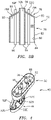
FIG. 3A is a sectioned view of the first housing portion of the drain mast shown inFIG. 3 alongcut line 3A-3A. -
FIG. 3B is a sectioned view of the second housing portion of the drain mast shown inFIG. 3 alongcut line 3B-3B. -
FIG. 4 is a rotated perspective view of the drain mast shown inFIG 3 . -
FIG. 5 is a perspective view of a drain mast embodiment according to the present invention. -
FIG. 6 is a partially sectioned view of the drain mast embodiment shown inFIG. 5 shown in a nacelle application. -
FIG. 7 is a perspective view of the drain mast shown inFIG. 3 . illustrating a print direction that may be used in an additive manufacturing methodology. -
FIG. 8 shows a plurality of drain mast produced using an additive manufacturing methodology. -
FIG. 9 is a diagrammatic view of a drain mast disposed within a nacelle application having a first fire zone and a second fire zone. - The detailed description of various embodiments herein makes reference to the accompanying drawings, which show various embodiments by way of illustration. Thus, the detailed description herein is presented for purposes of illustration only and not of limitation. For example, the steps recited in any of the method or process descriptions may be executed in any order and are not necessarily limited to the order presented.
- Furthermore, any reference to singular includes plural embodiments, and any reference to more than one component or step may include a singular embodiment or step. Also, any reference to attached, fixed, connected or the like may include permanent, removable, temporary, partial, full and/or any other possible attachment option. Additionally, any reference to without contact (or similar phrases) may also include reduced contact or minimal contact.
- Referring to
FIG. 1 , anacelle 20 for a gas turbine engine is illustrated according to various embodiments. Thenacelle 20 may be used on an aircraft. Thenacelle 20 may have a centerline A-A', and may include aninlet 22, afan cowl 24, and a thrust reverser 26. Thefan cowl 24 may comprise two halves pivotally mounted topylon 28, via one or more hinges. In this regard, thefan cowl 24 may comprise afirst fan cowl 24A (also referred to as a right-hand (RH) fan cowl) and asecond fan cowl 24B (also referred to as a left-hand (LH) fan cowl). In various embodiments, anexhaust nozzle 30 may extend from a turbine engine mounted within thenacelle 20. Thenacelle 20 may be coupled to apylon 28, which may in turn mount thenacelle 20 to an aircraft wing or aircraft body. -
FIG. 2 illustrates a schematic view of agas turbine engine 32 within anacelle 20. The orthogonal XYZ-axes are provided to facilitate the description herein. Thegas turbine engine 32 may include acore engine 34. Core air flow C flows throughcore engine 34 and is expelled through theexhaust outlet 36 surroundingtail cone 38. Thecore engine 34 drives afan 40 arranged in a bypass flow path B. Air within in the bypass flow-path B flows in the aft direction (z-direction) along bypass flow-path B. At least a portion of the bypass flow path B may be defined by thenacelle 20 and the inner fixed structure (IFS) 42. Afan case 44 may surround thefan 40. Thefan case 44 may be housed within afan nacelle 20. Thefan 40 may rotate about an engine centerline axis A-A'. - A
drain mast 46 according to the present disclosure as will be described herein may be configured for use in a gas turbine engine nacelle, within an APU compartment, or within any similar compartment of an aircraft that includes a drainage system. To facilitate the description herein, the presentdisclosure drain mast 46 is described below in the context of a nacelle application, but the presentdisclosure drain mast 46 is not limited to a nacelle applications. - Referring to
FIGS. 3, 3A ,3B, and 4 , adrain mast 46 is a unitary structure that includes afirst housing 48, asecond housing 50, and a plurality oftubes 52. Thefirst housing 48 and thesecond housing 50 are spaced apart from one another. Thetubes 52 extend between the first andsecond housings first housing 48 includes at least oneperipheral wall 54 and at least oneheader panel 56. Theperipheral wall 54 has aninterior surface 58, anexterior surface 60, afirst end 62, and a distalsecond end 64. Thesecond end 64 is disposed on the side facing thesecond housing 50. The interior andexterior surfaces peripheral wall 54 has an enclosed configuration that in part defines aninterior region 65 of thefirst housing 48. For example, in theexemplary drain mast 46 shown inFIGS. 3, 3A ,3B, and 4 , theperipheral wall 54 is a single wall extending in a substantially oval configuration. In other drain masts, theperipheral wall 54 may have a plurality of segments that collectively form the enclosed configuration. As will be explained below, in some drain masts the first housingperipheral wall 54 may be configured to cooperate with, or be a part of, a structure that forms a fluid seal, a fire seal, or both between adjacent compartments within the nacelle. - The first
housing header panel 56 is integrally connected with theperipheral wall 54 around the entire perimeter of theperipheral wall 54, and may be disposed at or adjacent thefirst end 62 of theperipheral wall 54. In such drain masts, theheader panel 56 encloses one end of thefirst housing 48 and provides a barrier that prevents fluid and/or fire migration through thefirst housing 48. In alternative drain masts, theheader panel 56 may be integrally connected with theperipheral wall 54 at other positions between the first and second ends 62, 64 of theperipheral wall 54. Theheader panel 56 includes afirst surface 66 and an oppositesecond surface 68. Thesecond surface 68 defines a portion of theinterior region 65 of thefirst housing 48. Theheader panel 56 includes a plurality ofapertures 70 extending between the first andsecond surfaces tube 52 within thedrain mast 46. On thefirst surface 66 of theheader panel 56, a plurality ofhollow connector segments 72 extend outwardly from theheader panel 56. Eachconnector segment 72 is aligned with a respective one of theapertures 70 disposed in theheader panel 56. On thesecond surface 68 of theheader panel 56, eachtube 52 is aligned with a respective one of theapertures 70, and extends outwardly from theheader panel 56. Collectively, each alignedconnector segment 72,header panel aperture 70, andtube 52 is part of a unitary structure that defines a fluid path through thefirst housing 48. Hence, there is no need for a seal disposed around a tube passing through the firsthousing header panel 56.FIGS. 3 and4 illustrate adrain mast 46 embodiment that includes a plurality of tubes 52 (e.g.,tubes 52A-52G) extending between thefirst housing 48 and thesecond housing 50. The present disclosure drain masts are not limited to having any particular number oftubes 52.FIG. 3A is sectional cut view taken throughtube 52E within thefirst housing 48, andFIG. 3B is sectional cut view taken throughtube 52E within thesecond housing 50. - Each of the
connector segments 72 extending outwardly from the firsthousing header panel 56 may be configured for attachment to a drain tube 74 (seeFIG. 9 ) extending from a collection point on or near the engine or other points within the nacelle. Eachconnector segment 72 may be, for example, configured with a portion of a threaded connector that permits connection/disconnection of thatconnector segment 72 with acorresponding drain tube 74. The present disclosure is not limited to anyparticular connector segment 72 configuration. - The
second housing 50 includes at least oneperipheral wall 76 and at least oneheader panel 78. Theperipheral wall 76 has aninterior surface 80, anexterior surface 82, afirst end 84, and a distalsecond end 86. Thesecond end 86 is disposed on the side facing thefirst housing 48. The interior andexterior surfaces peripheral wall 76 has an enclosed configuration that defines aninterior region 88 of thesecond housing 50. For example, in theexemplary drain mast 46 shown inFIGS. 3, 3A ,3B, and 4 , the second housingperipheral wall 76 is a single wall extending in a substantially oval configuration. Theperipheral wall 76 may have a plurality of segments that collectively form the enclosed configuration. As will be explained below, the second housingperipheral wall 76 may be configured to cooperate with, or be a part of, a structure that forms a fluid seal, a fire seal, or both. - The second
housing header panel 78 is integrally connected with the second housingperipheral wall 76 around the entire perimeter of theperipheral wall 76, and may be disposed at or adjacent thesecond end 86 of theperipheral wall 76. The secondhousing header panel 78 shown inFIGS. 3, 3A ,3B, and 4 may be described as "tented", having afirst portion 78A and asecond portion 78B disposed at an angle relative to one another (i.e., the first andsecond portions second portions housing header panel 78 are connected together, and each is connected to theperipheral wall 76. The secondhousing header panel 78 encloses one end of thesecond housing 50 and provides a barrier that prevents fluid and/or fire migration through thesecond housing 50. The present disclosure is not limited to any particular secondhousing header panel 78 configuration, other than one that encloses thesecond housing 50 and provides a barrier that prevents fluid and/or fire migration through thesecond housing 50. - The second
housing header panel 78 includes a first surface(s) 90 and an opposite second surface(s) 92. Thesecond surface 92 defines a portion of theinterior region 88 of thesecond housing 50. The secondhousing header panel 78 includes a plurality ofapertures 94 extending between the first andsecond surfaces tube 52 within thedrain mast 46. On thesecond surface 92 of the secondhousing header panel 78, a plurality ofdrain tube segments 96 extend outwardly from theheader panel 78. Eachdrain tube segment 96 is aligned with a respective one of theapertures 94 disposed in the secondhousing header panel 78. On thefirst surface 90 of theheader panel 78, each of the plurality oftubes 52 is aligned with a respective one of theapertures 94, and extends outwardly from theheader panel 78. Collectively, each aligneddrain tube segment 96, second housingheader panel aperture 94, andtube 52 is part of a unitary structure that defines a fluid path through thesecond housing 50. Hence, there is no need for a seal disposed around a tube passing through the secondhousing header panel 78. -
FIGS. 5 and 6 illustrate an embodiment of the presentdisclosure drain mast 146 that is also a unitary structure. In this embodiment, thedrain mast 146 includes a singleenclosed housing 98 extending between afirst end 100 and asecond end 102, afirst header panel 104, asecond header panel 106, and a plurality of tubes 152 (or other forms of fluid conduits) that extend internally within theenclosed housing 98 between the first and second ends 100, 102. Thefirst header panel 104 may be disposed at or adjacent thefirst end 100 and thesecond header panel 106 may be disposed at or adjacent thesecond end 102. Theenclosed housing 98 is formed by one or more walls that collectively define theenclosed housing 98. Theenclosed housing 98, thefirst header panel 104, and thesecond header panel 106 define an enclosedinterior compartment 116. In some embodiments, the enclosedinterior compartment 116 may be hollow, including only thetubes 152 extending between the first andsecond header panels interior compartment 116 may not be completely hollow and may for example, include structural elements that support thetubes 152 and create interior subcompartments within theinterior compartment 116, or theinterior compartment 116 may be filled with a lightweight material (e.g., a porous material) that provides structural support to thetubes 152 and to thedrain mast 146 housing itself, or the like. Like other embodiments of the presentdisclosure drain mast 146, these embodiments may include a plurality ofconnector segments 72 extending outwardly from thefirst header panel 104, and/or a plurality of drain tube segments 96 (e.g., seeFIG. 3 ) extending outwardly from thesecond header panel 106. Theenclosed housing 98 of thedrain mast 146 embodiments described with respect toFIGS. 5 and 6 may provide additional benefits. For example, as described above a drain mast can extend across a plurality of nacelle compartments (e.g., compartments 108, 110 - SeeFIG. 9 ), and each nacelle compartment may be a designated fire zone ("DFZ"). Embodiments of thepresent drain mast 146 can be configured to prevent fluid leakage between adjacent nacelle compartments, and can be configured to provide one or more passages for flammable liquids such as hydraulic oil, fuel, oil, etc. through a nacelle compartment. Theenclosed housing 98 of thedrain mast 146 embodiments described with respect toFIGS. 5 and 6 provides a barrier between the nacelle compartment and thetubes 152 themselves; i.e., thetubes 152 are disposed withininterior compartment 116. Hence, theenclosed housing 98 provides a barrier between the environment in the nacelle compartment (e.g., See alsoFIG. 9 , nacelle compartment 110) and thetubes 152; e.g., potentially separating thetubes 152 from an elevated temperature or flame within thenacelle compartment 110. Furthermore, theinterior compartment 116 can also function to restrict the flow of fluids, preventing their distribution into thenacelle compartment 110. For example in the event a fluid leak (e.g., via a ruptured tube 152) is developed within theinterior compartment 116, theenclosed housing 98 may be configured to prevent such leaked fluid from exiting theenclosed housing 98 and passing into thenacelle compartment 110. Thedrain mast 146 may include a mechanism operable to collect the fluids leaked within theenclosed housing 98, and direct those collected fluids away from thedrain mast 146 appropriately. For example, in thedrain mast 146 embodiment shown inFIG. 6 , thedrain mast 146 includes adrainage port 114 disposed in thesecond header panel 106 that may be fluidly connected to adrain tube segment 96. Hence, fluid leaked within theenclosed housing 98 may be collected and safely drained to the exterior of the nacelle via thedrainage port 114. - An additive manufacturing process may be used to produce present disclosure drain mastembodiments as a unitary structure. A variety of different additive manufacturing processes are known and may be used. A specific example of an acceptable additive manufacturing process is one that utilizes a laser powder bed fusion technique. A
drain mast 146 according to the present disclosure may be comprised of a number of different materials and is therefore not limited to any particular material. In those instances wherein a presentdisclosure drain mast drain mast FIG. 7 provides a diagrammatic view of adrain mast 46 embodiment that may be formed using an additive manufacturing process.FIG. 7 also indicates a print direction that may be used in such an additive manufacturing process.FIG. 8 illustrates a plurality ofdrain masts 46 that have been produced using an additive manufacturing process in a batch mode; e.g., in a single print. The ability to produce a plurality of presentdisclosure drain masts 46 in a single operation illustrates the manufacturability of the present disclosure drain masts. - Aspects of the present disclosure resolve numerous issues associated with prior art drain masts. As indicated above, drain masts are often required to provide fluid passages between different compartments within a nacelle, and those compartments often have different fire zone ratings. Hence, drain masts are often relied upon to create at least a part of fluid and fire sealing between adjacent compartments. Prior art drain systems providing sealing between adjacent compartments often included a large number of individual parts that were difficult to produce, install, and maintain. Present
disclosure drain masts independent tubes 52, or seals forindependent tubes 52, configured in a manner that controls fluid leakage or inhibits fire propagation between adjacent compartments. The absence of independent tubes and tube seals substantially decreases efforts that would otherwise be associated with installing the independent tubes, tube seals, installing thedrain mast drain mast -
FIG. 9 diagrammatically illustrates a presentdisclosure drain mast 46 embodiment in a nacelle application. Thefirst housing 48 is positioned at the interface between a firstfire zone compartment 108 and a secondfire zone compartment 110.Drainage tubes 74 from various collection points within the nacelle extend into the firstfire zone compartment 108 and connect with theconnector segments 72 extending outwardly from thefirst housing 48. Theperipheral wall 54 of thefirst housing 48 provides a sealing surface for the interface between the first and second fire zone compartments 108, 110. The unitary structure of theconnector segments 72,header panel 56, andtubes 52 define a fire seal and a leak-free fluid path. Thesecond housing 50 is positioned at anexterior panel 112 of the nacelle. Theperipheral wall 76 of thesecond housing 50 provides a sealing surface with theexterior panel 112. Here again, the unitary structure of thesecond housing 50 components define a fire seal and a leak-free fluid path. - The
tubes 52, theconnector segments 72, or thedrain tube segments 96, or any combination thereof, may include integral indicators (e.g., labels) that identify the drain tube and/or the collection point that it is associated with in the nacelle. For example, these indicators may be integrated into the design of the drain mast. And/or may be printed on the drain tubes concurrently during the manufacturing of the tubes, etc. The indicators may facilitate installation of thedrain mast 46, maintenance efforts associated with thedrain mast 46, and/or diagnostic trouble shooting. In thedrain masts 46, one or more sensors may be associated with particular drain tubes within thedrain mast 46. The sensors may be configured to provide an indication of fluid flow within the tube, and thereby provide an indication of potential leakage within the nacelle. The aforesaid sensors may be implemented as part of a prognostic health monitoring ("PHM") system. - In the detailed description herein, references to "one embodiment", "an embodiment", "various embodiments", etc., indicate that the embodiment described may include a particular feature, structure, or characteristic, but every embodiment may not necessarily include the particular feature, structure, or characteristic. Moreover, such phrases are not necessarily referring to the same embodiment. Further, when a particular feature, structure, or characteristic is described in connection with an embodiment, it is submitted that it is within the knowledge of one skilled in the art to affect such feature, structure, or characteristic in connection with other embodiments whether or not explicitly described. After reading the description, it will be apparent to one skilled in the relevant art(s) how to implement the disclosure in alternative embodiments.
- Benefits, other advantages, and solutions to problems have been described herein with regard to specific embodiments. Furthermore, the connecting lines shown in the various figures contained herein are intended to represent various functional relationships and/or physical couplings between the various elements. It should be noted that many alternative or additional functional relationships or physical connections may be present in a practical system. However, the benefits, advantages, solutions to problems, and any elements that may cause any benefit, advantage, or solution to occur or become more pronounced are not to be construed as critical, required, or essential features or elements of the inventions. The scope of the inventions is accordingly to be limited by nothing other than the appended claims, in which reference to an element in the singular is not intended to mean "one and only one" unless explicitly so stated, but rather "one or more." Moreover, where a phrase similar to "at least one of A, B, or C" is used in the claims, it is intended that the phrase be interpreted to mean that A alone may be present in an embodiment, B alone may be present in an embodiment, C alone may be present in an embodiment, or that any combination of the elements A, B and C may be present in a single embodiment; for example, A and B, A and C, B and C, or A and B and C. Different cross-hatching is used throughout the figures to denote different parts but not necessarily to denote the same or different materials. As used herein, the terms "comprises", "comprising", or any other variation thereof, are intended to cover a non-exclusive inclusion, such that a process, method, article, or apparatus that comprises a list of elements does not include only those elements but may include other elements not expressly listed or inherent to such process, method, article, or apparatus.
- As stated above, embodiments of the present
disclosure drain mast 146 are described above in the context of a gas turbine engine nacelle application to facilitate the description herein, but the presentdisclosure drain mast 146 embodiments are not limited to a nacelle application. The presentdisclosure drain mast 146 embodiments may be used in a variety of different applications (e.g., APU compartments, etc.) where safe and contained drainage of fluids, including flammable fluids, within and through aircraft fire zones, and/or fluid sealing between adjacent compartments, and/or fire sealing between adjacent compartments is desired. The presentdisclosure drain master 146 embodiments provide particular utility in gas turbine engine nacelle applications, but are not limited thereto.
Claims (5)
- A drain mast (146), comprising:a first header panel (104);a second header panel (106);at least one enclosure wall (98); anda plurality of tubes (152);wherein the first header panel (104), the second header panel (106), the plurality of tubes (152), and the at least one enclosure wall (98) are integrally formed as a unitary structure, and the first header panel (104) is separated from the second header panel (106), and the first header panel (104), the second header panel (106), and the at least one enclosure wall (98) collectively define an enclosed interior compartment (116), and the plurality of tubes (152) extend between the first header panel (104) and the second header panel (106) within the interior compartment (116), and the drain mast (146) is configured to provide a plurality of fluid paths through the drain mast (146), each fluid path extending through the first header panel (104), one of the plurality of tubes (152), and the second header panel (106).
- The drain mast (146) of claim 1, wherein the drain mast (146) is configured to contain fluids disposed outside of the tubes (152) within the interior compartment (116).
- The drain mast (146) of claims 1 or 2, wherein the at least one enclosure wall (98) has a first end (100) and a distal second end (102), and the first header panel (104) is integrally formed with the at least one enclosure wall (98) adjacent the first end (100).
- The drain mast (146) of any preceding claim, wherein the at least one enclosure wall (98) has a or the first end (100) and a or the distal second end (102), and the second header panel (106) is integrally formed with the at least one enclosure wall (98) adjacent the second end (102).
- The drain mast (146) of any preceding claim, further comprising a drainage port (114) disposed within the second header panel (106), wherein the drainage port (114) is configured to receive the fluids disposed outside of the tubes (152) within the interior compartment (116), and provide a fluid passage outside of the interior compartment (116).
Applications Claiming Priority (1)
| Application Number | Priority Date | Filing Date | Title |
|---|---|---|---|
| US16/404,270 US11186354B2 (en) | 2019-05-06 | 2019-05-06 | Unitary drain mast |
Publications (2)
| Publication Number | Publication Date |
|---|---|
| EP3736206A1 EP3736206A1 (en) | 2020-11-11 |
| EP3736206B1 true EP3736206B1 (en) | 2022-03-30 |
Family
ID=68762475
Family Applications (1)
| Application Number | Title | Priority Date | Filing Date |
|---|---|---|---|
| EP19212695.1A Active EP3736206B1 (en) | 2019-05-06 | 2019-11-29 | Unitary drain mast |
Country Status (2)
| Country | Link |
|---|---|
| US (1) | US11186354B2 (en) |
| EP (1) | EP3736206B1 (en) |
Families Citing this family (1)
| Publication number | Priority date | Publication date | Assignee | Title |
|---|---|---|---|---|
| CN116066242B (en) * | 2023-02-27 | 2025-11-21 | 中国航发湖南动力机械研究所 | Water and oil centralized discharge structure for auxiliary power device |
Family Cites Families (22)
| Publication number | Priority date | Publication date | Assignee | Title |
|---|---|---|---|---|
| US4715561A (en) * | 1986-11-03 | 1987-12-29 | East/West Industries, Inc. | Drain assembly for aircraft |
| US5290996A (en) * | 1992-02-21 | 1994-03-01 | The B. F. Goodrich Company | Modular drainmast for aircraft |
| US5285636A (en) | 1992-10-28 | 1994-02-15 | General Electric Company | Diagnostic drain mast for a gas turbine engine |
| US5511573A (en) * | 1994-10-24 | 1996-04-30 | K N Energy, Inc. | Contaminated valve containment device |
| DE19528685C2 (en) * | 1995-08-03 | 1999-02-18 | Berndt Saurwein | Device for producing installation breakthroughs |
| US6578361B1 (en) | 2001-08-30 | 2003-06-17 | General Electric Co. | Methods and apparatus for determining engine cavity leakage |
| US7055863B1 (en) * | 2003-12-30 | 2006-06-06 | Commeville Marc J | Containment device and method for hose bibs and the like |
| GB2446147B (en) * | 2007-01-30 | 2009-02-18 | Rolls Royce Plc | Aeroengine drain assembly |
| US20110121137A1 (en) | 2009-11-24 | 2011-05-26 | Electrofilm Manufacturing Company Llc | Method and apparatus for directing waste away from aircraft |
| BRPI1106760A2 (en) * | 2011-10-28 | 2013-11-05 | Wladimir De Freitas Silvestre | PIPE SUPPORT AND APPLICATION METHOD OF A PIPE SUPPORT IN A SLAB |
| US8898974B1 (en) * | 2012-11-20 | 2014-12-02 | Amazon Technologies, Inc. | Electrical panel structures |
| US9315253B2 (en) | 2013-09-18 | 2016-04-19 | Goodrich Corporation | Drain masts |
| FR3021028B1 (en) | 2014-05-15 | 2016-06-24 | Dassault Aviat | DRAINAGE MAT AND METHOD THEREOF |
| US9453595B2 (en) | 2014-05-21 | 2016-09-27 | Honeywell International Inc. | Drain mast seal having segregated chambers |
| US10487690B2 (en) | 2014-08-18 | 2019-11-26 | Rohr, Inc. | Actively controlled cooling air exhaust door on an aircraft engine nacelle |
| US9752818B2 (en) * | 2015-12-22 | 2017-09-05 | Whirlpool Corporation | Umbilical for pass through in vacuum insulated refrigerator structures |
| US20170259900A1 (en) | 2016-03-11 | 2017-09-14 | Goodrich Corporation | Fluid discharge booster for a drain mast |
| ES2832462T3 (en) | 2016-10-20 | 2021-06-10 | Airbus Operations Sl | Drainage mast of an aircraft |
| US10823057B2 (en) | 2017-03-08 | 2020-11-03 | Rohr, Inc. | Outlet tube vent with flow energizing features |
| US10472082B2 (en) | 2017-03-20 | 2019-11-12 | Bell Helicopter Textron Inc. | Fume tight sock collector/box |
| US10808577B2 (en) | 2017-03-28 | 2020-10-20 | The Boeing Company | Aerodynamic drainage device |
| US10717514B2 (en) * | 2018-03-09 | 2020-07-21 | Senior Ip Gmbh | Integrated drain mast structure |
-
2019
- 2019-05-06 US US16/404,270 patent/US11186354B2/en active Active
- 2019-11-29 EP EP19212695.1A patent/EP3736206B1/en active Active
Also Published As
| Publication number | Publication date |
|---|---|
| US20200354037A1 (en) | 2020-11-12 |
| US11186354B2 (en) | 2021-11-30 |
| EP3736206A1 (en) | 2020-11-11 |
Similar Documents
| Publication | Publication Date | Title |
|---|---|---|
| EP2870341B1 (en) | Gas turbine engine oil tank with integrated packaging configuration | |
| EP2607651B1 (en) | Electronic unit mounting | |
| EP3831718B1 (en) | Firewall assemblies for hybrid electric aircraft power plants | |
| EP2895392B1 (en) | Metallic sandwich structure having small bend radius | |
| US9934885B2 (en) | Electrical Harness | |
| US20120104162A1 (en) | Pylon arrangement for open structure | |
| EP3112605B1 (en) | Seals for gas turbine engine core nacelle cowlings | |
| US9719426B2 (en) | Mounting arrangement | |
| EP3131817B1 (en) | Engine inlet configuration | |
| CA2890421A1 (en) | Aircraft propelling assembly including a duct forming a thermal barrier integrated in the caisson of the rigid structure of the engine mounting system | |
| US11186354B2 (en) | Unitary drain mast | |
| KR102342428B1 (en) | Integrated discharge mast structure | |
| US11085328B2 (en) | Assembly for sealing an annular gap between an inner structure and an outer structure | |
| EP3305373B1 (en) | Multi-directional fire extinguishing nozzle | |
| EP2053205B1 (en) | Gas turbine engine systems involving integrated fluid conduits | |
| EP2881327B1 (en) | Aircraft thrust reversing assembly IFS support structure | |
| EP3171144A1 (en) | Instrumentation adaptor for a gas turbine engine | |
| US11761349B2 (en) | Bearing housing for a two-wheel air cycle machine | |
| EP4462576A1 (en) | Energy storage system for an aircraft having a ventilation system | |
| CN101842628B (en) | Sealing joint with integrated mating surface | |
| GB2635150A (en) | Aeroengine and process of operating an aeroengine |
Legal Events
| Date | Code | Title | Description |
|---|---|---|---|
| PUAI | Public reference made under article 153(3) epc to a published international application that has entered the european phase |
Free format text: ORIGINAL CODE: 0009012 |
|
| STAA | Information on the status of an ep patent application or granted ep patent |
Free format text: STATUS: THE APPLICATION HAS BEEN PUBLISHED |
|
| AK | Designated contracting states |
Kind code of ref document: A1 Designated state(s): AL AT BE BG CH CY CZ DE DK EE ES FI FR GB GR HR HU IE IS IT LI LT LU LV MC MK MT NL NO PL PT RO RS SE SI SK SM TR |
|
| AX | Request for extension of the european patent |
Extension state: BA ME |
|
| STAA | Information on the status of an ep patent application or granted ep patent |
Free format text: STATUS: REQUEST FOR EXAMINATION WAS MADE |
|
| 17P | Request for examination filed |
Effective date: 20210511 |
|
| RBV | Designated contracting states (corrected) |
Designated state(s): AL AT BE BG CH CY CZ DE DK EE ES FI FR GB GR HR HU IE IS IT LI LT LU LV MC MK MT NL NO PL PT RO RS SE SI SK SM TR |
|
| GRAP | Despatch of communication of intention to grant a patent |
Free format text: ORIGINAL CODE: EPIDOSNIGR1 |
|
| STAA | Information on the status of an ep patent application or granted ep patent |
Free format text: STATUS: GRANT OF PATENT IS INTENDED |
|
| INTG | Intention to grant announced |
Effective date: 20211012 |
|
| GRAS | Grant fee paid |
Free format text: ORIGINAL CODE: EPIDOSNIGR3 |
|
| GRAA | (expected) grant |
Free format text: ORIGINAL CODE: 0009210 |
|
| STAA | Information on the status of an ep patent application or granted ep patent |
Free format text: STATUS: THE PATENT HAS BEEN GRANTED |
|
| AK | Designated contracting states |
Kind code of ref document: B1 Designated state(s): AL AT BE BG CH CY CZ DE DK EE ES FI FR GB GR HR HU IE IS IT LI LT LU LV MC MK MT NL NO PL PT RO RS SE SI SK SM TR |
|
| REG | Reference to a national code |
Ref country code: GB Ref legal event code: FG4D |
|
| REG | Reference to a national code |
Ref country code: CH Ref legal event code: EP |
|
| REG | Reference to a national code |
Ref country code: DE Ref legal event code: R096 Ref document number: 602019013041 Country of ref document: DE |
|
| REG | Reference to a national code |
Ref country code: AT Ref legal event code: REF Ref document number: 1478969 Country of ref document: AT Kind code of ref document: T Effective date: 20220415 |
|
| REG | Reference to a national code |
Ref country code: IE Ref legal event code: FG4D |
|
| REG | Reference to a national code |
Ref country code: LT Ref legal event code: MG9D |
|
| PG25 | Lapsed in a contracting state [announced via postgrant information from national office to epo] |
Ref country code: SE Free format text: LAPSE BECAUSE OF FAILURE TO SUBMIT A TRANSLATION OF THE DESCRIPTION OR TO PAY THE FEE WITHIN THE PRESCRIBED TIME-LIMIT Effective date: 20220330 Ref country code: RS Free format text: LAPSE BECAUSE OF FAILURE TO SUBMIT A TRANSLATION OF THE DESCRIPTION OR TO PAY THE FEE WITHIN THE PRESCRIBED TIME-LIMIT Effective date: 20220330 Ref country code: NO Free format text: LAPSE BECAUSE OF FAILURE TO SUBMIT A TRANSLATION OF THE DESCRIPTION OR TO PAY THE FEE WITHIN THE PRESCRIBED TIME-LIMIT Effective date: 20220630 Ref country code: LT Free format text: LAPSE BECAUSE OF FAILURE TO SUBMIT A TRANSLATION OF THE DESCRIPTION OR TO PAY THE FEE WITHIN THE PRESCRIBED TIME-LIMIT Effective date: 20220330 Ref country code: HR Free format text: LAPSE BECAUSE OF FAILURE TO SUBMIT A TRANSLATION OF THE DESCRIPTION OR TO PAY THE FEE WITHIN THE PRESCRIBED TIME-LIMIT Effective date: 20220330 Ref country code: BG Free format text: LAPSE BECAUSE OF FAILURE TO SUBMIT A TRANSLATION OF THE DESCRIPTION OR TO PAY THE FEE WITHIN THE PRESCRIBED TIME-LIMIT Effective date: 20220630 |
|
| REG | Reference to a national code |
Ref country code: NL Ref legal event code: MP Effective date: 20220330 |
|
| REG | Reference to a national code |
Ref country code: AT Ref legal event code: MK05 Ref document number: 1478969 Country of ref document: AT Kind code of ref document: T Effective date: 20220330 |
|
| PG25 | Lapsed in a contracting state [announced via postgrant information from national office to epo] |
Ref country code: LV Free format text: LAPSE BECAUSE OF FAILURE TO SUBMIT A TRANSLATION OF THE DESCRIPTION OR TO PAY THE FEE WITHIN THE PRESCRIBED TIME-LIMIT Effective date: 20220330 Ref country code: GR Free format text: LAPSE BECAUSE OF FAILURE TO SUBMIT A TRANSLATION OF THE DESCRIPTION OR TO PAY THE FEE WITHIN THE PRESCRIBED TIME-LIMIT Effective date: 20220701 Ref country code: FI Free format text: LAPSE BECAUSE OF FAILURE TO SUBMIT A TRANSLATION OF THE DESCRIPTION OR TO PAY THE FEE WITHIN THE PRESCRIBED TIME-LIMIT Effective date: 20220330 |
|
| PG25 | Lapsed in a contracting state [announced via postgrant information from national office to epo] |
Ref country code: NL Free format text: LAPSE BECAUSE OF FAILURE TO SUBMIT A TRANSLATION OF THE DESCRIPTION OR TO PAY THE FEE WITHIN THE PRESCRIBED TIME-LIMIT Effective date: 20220330 |
|
| PG25 | Lapsed in a contracting state [announced via postgrant information from national office to epo] |
Ref country code: SM Free format text: LAPSE BECAUSE OF FAILURE TO SUBMIT A TRANSLATION OF THE DESCRIPTION OR TO PAY THE FEE WITHIN THE PRESCRIBED TIME-LIMIT Effective date: 20220330 Ref country code: SK Free format text: LAPSE BECAUSE OF FAILURE TO SUBMIT A TRANSLATION OF THE DESCRIPTION OR TO PAY THE FEE WITHIN THE PRESCRIBED TIME-LIMIT Effective date: 20220330 Ref country code: RO Free format text: LAPSE BECAUSE OF FAILURE TO SUBMIT A TRANSLATION OF THE DESCRIPTION OR TO PAY THE FEE WITHIN THE PRESCRIBED TIME-LIMIT Effective date: 20220330 Ref country code: PT Free format text: LAPSE BECAUSE OF FAILURE TO SUBMIT A TRANSLATION OF THE DESCRIPTION OR TO PAY THE FEE WITHIN THE PRESCRIBED TIME-LIMIT Effective date: 20220801 Ref country code: ES Free format text: LAPSE BECAUSE OF FAILURE TO SUBMIT A TRANSLATION OF THE DESCRIPTION OR TO PAY THE FEE WITHIN THE PRESCRIBED TIME-LIMIT Effective date: 20220330 Ref country code: EE Free format text: LAPSE BECAUSE OF FAILURE TO SUBMIT A TRANSLATION OF THE DESCRIPTION OR TO PAY THE FEE WITHIN THE PRESCRIBED TIME-LIMIT Effective date: 20220330 Ref country code: CZ Free format text: LAPSE BECAUSE OF FAILURE TO SUBMIT A TRANSLATION OF THE DESCRIPTION OR TO PAY THE FEE WITHIN THE PRESCRIBED TIME-LIMIT Effective date: 20220330 Ref country code: AT Free format text: LAPSE BECAUSE OF FAILURE TO SUBMIT A TRANSLATION OF THE DESCRIPTION OR TO PAY THE FEE WITHIN THE PRESCRIBED TIME-LIMIT Effective date: 20220330 |
|
| PG25 | Lapsed in a contracting state [announced via postgrant information from national office to epo] |
Ref country code: PL Free format text: LAPSE BECAUSE OF FAILURE TO SUBMIT A TRANSLATION OF THE DESCRIPTION OR TO PAY THE FEE WITHIN THE PRESCRIBED TIME-LIMIT Effective date: 20220330 Ref country code: IS Free format text: LAPSE BECAUSE OF FAILURE TO SUBMIT A TRANSLATION OF THE DESCRIPTION OR TO PAY THE FEE WITHIN THE PRESCRIBED TIME-LIMIT Effective date: 20220730 Ref country code: AL Free format text: LAPSE BECAUSE OF FAILURE TO SUBMIT A TRANSLATION OF THE DESCRIPTION OR TO PAY THE FEE WITHIN THE PRESCRIBED TIME-LIMIT Effective date: 20220330 |
|
| REG | Reference to a national code |
Ref country code: DE Ref legal event code: R097 Ref document number: 602019013041 Country of ref document: DE |
|
| PG25 | Lapsed in a contracting state [announced via postgrant information from national office to epo] |
Ref country code: DK Free format text: LAPSE BECAUSE OF FAILURE TO SUBMIT A TRANSLATION OF THE DESCRIPTION OR TO PAY THE FEE WITHIN THE PRESCRIBED TIME-LIMIT Effective date: 20220330 |
|
| PLBE | No opposition filed within time limit |
Free format text: ORIGINAL CODE: 0009261 |
|
| STAA | Information on the status of an ep patent application or granted ep patent |
Free format text: STATUS: NO OPPOSITION FILED WITHIN TIME LIMIT |
|
| 26N | No opposition filed |
Effective date: 20230103 |
|
| PG25 | Lapsed in a contracting state [announced via postgrant information from national office to epo] |
Ref country code: SI Free format text: LAPSE BECAUSE OF FAILURE TO SUBMIT A TRANSLATION OF THE DESCRIPTION OR TO PAY THE FEE WITHIN THE PRESCRIBED TIME-LIMIT Effective date: 20220330 |
|
| PG25 | Lapsed in a contracting state [announced via postgrant information from national office to epo] |
Ref country code: MC Free format text: LAPSE BECAUSE OF FAILURE TO SUBMIT A TRANSLATION OF THE DESCRIPTION OR TO PAY THE FEE WITHIN THE PRESCRIBED TIME-LIMIT Effective date: 20220330 |
|
| REG | Reference to a national code |
Ref country code: CH Ref legal event code: PL |
|
| REG | Reference to a national code |
Ref country code: BE Ref legal event code: MM Effective date: 20221130 |
|
| PG25 | Lapsed in a contracting state [announced via postgrant information from national office to epo] |
Ref country code: LI Free format text: LAPSE BECAUSE OF NON-PAYMENT OF DUE FEES Effective date: 20221130 Ref country code: IT Free format text: LAPSE BECAUSE OF FAILURE TO SUBMIT A TRANSLATION OF THE DESCRIPTION OR TO PAY THE FEE WITHIN THE PRESCRIBED TIME-LIMIT Effective date: 20220330 Ref country code: CH Free format text: LAPSE BECAUSE OF NON-PAYMENT OF DUE FEES Effective date: 20221130 |
|
| PG25 | Lapsed in a contracting state [announced via postgrant information from national office to epo] |
Ref country code: LU Free format text: LAPSE BECAUSE OF NON-PAYMENT OF DUE FEES Effective date: 20221129 |
|
| PG25 | Lapsed in a contracting state [announced via postgrant information from national office to epo] |
Ref country code: IE Free format text: LAPSE BECAUSE OF NON-PAYMENT OF DUE FEES Effective date: 20221129 |
|
| PG25 | Lapsed in a contracting state [announced via postgrant information from national office to epo] |
Ref country code: BE Free format text: LAPSE BECAUSE OF NON-PAYMENT OF DUE FEES Effective date: 20221130 |
|
| PG25 | Lapsed in a contracting state [announced via postgrant information from national office to epo] |
Ref country code: CY Free format text: LAPSE BECAUSE OF FAILURE TO SUBMIT A TRANSLATION OF THE DESCRIPTION OR TO PAY THE FEE WITHIN THE PRESCRIBED TIME-LIMIT Effective date: 20220330 |
|
| PG25 | Lapsed in a contracting state [announced via postgrant information from national office to epo] |
Ref country code: MK Free format text: LAPSE BECAUSE OF FAILURE TO SUBMIT A TRANSLATION OF THE DESCRIPTION OR TO PAY THE FEE WITHIN THE PRESCRIBED TIME-LIMIT Effective date: 20220330 Ref country code: HU Free format text: LAPSE BECAUSE OF FAILURE TO SUBMIT A TRANSLATION OF THE DESCRIPTION OR TO PAY THE FEE WITHIN THE PRESCRIBED TIME-LIMIT; INVALID AB INITIO Effective date: 20191129 |
|
| PG25 | Lapsed in a contracting state [announced via postgrant information from national office to epo] |
Ref country code: MT Free format text: LAPSE BECAUSE OF FAILURE TO SUBMIT A TRANSLATION OF THE DESCRIPTION OR TO PAY THE FEE WITHIN THE PRESCRIBED TIME-LIMIT Effective date: 20220330 |
|
| PG25 | Lapsed in a contracting state [announced via postgrant information from national office to epo] |
Ref country code: TR Free format text: LAPSE BECAUSE OF FAILURE TO SUBMIT A TRANSLATION OF THE DESCRIPTION OR TO PAY THE FEE WITHIN THE PRESCRIBED TIME-LIMIT Effective date: 20220330 |
|
| PGFP | Annual fee paid to national office [announced via postgrant information from national office to epo] |
Ref country code: DE Payment date: 20251022 Year of fee payment: 7 |
|
| PGFP | Annual fee paid to national office [announced via postgrant information from national office to epo] |
Ref country code: GB Payment date: 20251022 Year of fee payment: 7 |
|
| PGFP | Annual fee paid to national office [announced via postgrant information from national office to epo] |
Ref country code: FR Payment date: 20251022 Year of fee payment: 7 |
|
| P01 | Opt-out of the competence of the unified patent court (upc) registered |
Free format text: CASE NUMBER: UPC_APP_0018973_3736206/2025 Effective date: 20251222 |