EP3131817B1 - Engine inlet configuration - Google Patents
Engine inlet configuration Download PDFInfo
- Publication number
- EP3131817B1 EP3131817B1 EP15779782.0A EP15779782A EP3131817B1 EP 3131817 B1 EP3131817 B1 EP 3131817B1 EP 15779782 A EP15779782 A EP 15779782A EP 3131817 B1 EP3131817 B1 EP 3131817B1
- Authority
- EP
- European Patent Office
- Prior art keywords
- inlet
- inlet duct
- engine
- aircraft
- duct
- Prior art date
- Legal status (The legal status is an assumption and is not a legal conclusion. Google has not performed a legal analysis and makes no representation as to the accuracy of the status listed.)
- Active
Links
- 230000037406 food intake Effects 0.000 claims description 2
- 238000009434 installation Methods 0.000 description 10
- 238000002485 combustion reaction Methods 0.000 description 2
- 230000001419 dependent effect Effects 0.000 description 2
- 238000004519 manufacturing process Methods 0.000 description 2
- 238000000034 method Methods 0.000 description 2
- 230000037361 pathway Effects 0.000 description 2
- 238000007789 sealing Methods 0.000 description 2
- RTAQQCXQSZGOHL-UHFFFAOYSA-N Titanium Chemical compound [Ti] RTAQQCXQSZGOHL-UHFFFAOYSA-N 0.000 description 1
- 230000004075 alteration Effects 0.000 description 1
- 238000004891 communication Methods 0.000 description 1
- 238000007689 inspection Methods 0.000 description 1
- 239000000463 material Substances 0.000 description 1
- 238000006467 substitution reaction Methods 0.000 description 1
- 229910052719 titanium Inorganic materials 0.000 description 1
- 239000010936 titanium Substances 0.000 description 1
Images


Classifications
-
- B—PERFORMING OPERATIONS; TRANSPORTING
- B64—AIRCRAFT; AVIATION; COSMONAUTICS
- B64D—EQUIPMENT FOR FITTING IN OR TO AIRCRAFT; FLIGHT SUITS; PARACHUTES; ARRANGEMENT OR MOUNTING OF POWER PLANTS OR PROPULSION TRANSMISSIONS IN AIRCRAFT
- B64D33/00—Arrangements in aircraft of power plant parts or auxiliaries not otherwise provided for
- B64D33/02—Arrangements in aircraft of power plant parts or auxiliaries not otherwise provided for of combustion air intakes
- B64D2033/0246—Arrangements in aircraft of power plant parts or auxiliaries not otherwise provided for of combustion air intakes comprising particle separators
-
- B—PERFORMING OPERATIONS; TRANSPORTING
- B64—AIRCRAFT; AVIATION; COSMONAUTICS
- B64D—EQUIPMENT FOR FITTING IN OR TO AIRCRAFT; FLIGHT SUITS; PARACHUTES; ARRANGEMENT OR MOUNTING OF POWER PLANTS OR PROPULSION TRANSMISSIONS IN AIRCRAFT
- B64D33/00—Arrangements in aircraft of power plant parts or auxiliaries not otherwise provided for
- B64D33/02—Arrangements in aircraft of power plant parts or auxiliaries not otherwise provided for of combustion air intakes
- B64D2033/0253—Arrangements in aircraft of power plant parts or auxiliaries not otherwise provided for of combustion air intakes specially adapted for particular type of aircraft
Definitions
- US 2013/0313371 A1 discloses an inlet duct for an engine or multiple engines includes two or more joining duct legs and a pressure relief pathway located at each duct leg to condition inlet airflow from the duct legs.
- US 2013/0313371 A1 's method of operating an aircraft includes urging an inlet airflow into two or more duct openings disposed at a fuselage of the aircraft. The inlet airflow is urged through two or more converging inlet duct legs extending from the two or more duct openings toward an engine inlet. A portion of the inlet airflow is flowed from at least one inlet duct leg of the two or more inlet duct legs into a pressure relief pathway.
- An inlet duct for an engine or multiple engines includes one or more inlet duct legs and a bypass leg extending from an inlet duct leg of the one or more inlet duct legs through a bypass opening.
- EP 1 482 228 B1 discloses fireproof seal comprises 2 or more concentric seal elements having confronting ends that are out of registration.
- the seal elements are adapted to be placed in use in sealing relationship with one element at least partially encircling the other.
- An independent claim is also included for a method for sealing a pipe in a hole formed in wall using a seal comprising applying a first seal element around the pipe adjacent to the wall, applying a second or subsequent seal element at least partially to encircle the first, and securing the resulting seal to the wall and around the pipe.
- the inlet duct 24 is bifurcated, with duct legs 28 each extending from an inlet opening 30 at each lateral side of the airframe 12 to a single duct outlet 32 at the engine 20.
- the inlet duct 24 extends through a portion of the airframe 12 referred to as a main rotor pylon (MRP) 34.
- the MRP 34 houses the gearbox 22 for the main rotor assembly 16, which is operably connected to the engine 20.
- the inlet duct 24 is bifurcated at least in part to route the inlet duct 24 around the gearbox 22 and the main rotor assembly 16.
- the MRP 34 is bounded longitudinally by the inlet openings 30 and an engine compartment firewall 36 separating the MRP 34 from an engine compartment 38 at which the engine 20 is located.
Landscapes
- Engineering & Computer Science (AREA)
- Aviation & Aerospace Engineering (AREA)
- Chemical & Material Sciences (AREA)
- Combustion & Propulsion (AREA)
- Structures Of Non-Positive Displacement Pumps (AREA)
- Mechanical Engineering (AREA)
Description
- The subject matter disclosed herein relates to a rotary winged aircraft with engine inlets, more specifically, to installation of engine inlet ducts and/or cowling.
- Engines for, for example, aircraft such as helicopters or other rotorcraft utilize engine inlet ducting to direct airflow into the compressor of the engine. Some systems, for example, single engine systems, utilize a bifurcated inlet duct, which takes two airflow streams and directs them to the compressor inlet. The duct extends from an inlet located at a portion of the airframe such as the main rotor pylon (MRP) and extends through the MRP and airframe to an engine inlet at the engine front frame. The duct is typically secured directly and rigidly to the engine front frame at the duct outlet, and secured to the inlet at the MRP. Secured at each end, the inlet duct is held rigidly in place.
- In some aircraft, however, the duct length is quite long making installation of the duct difficult due to manufacturing and assembly tolerance stackups between the engine front frame, the MRP and the inlet duct. Further, in some configurations, the inlet duct installation points may be inaccessible.
-
US 2013/0313371 A1 discloses an inlet duct for an engine or multiple engines includes two or more joining duct legs and a pressure relief pathway located at each duct leg to condition inlet airflow from the duct legs.US 2013/0313371 A1 's method of operating an aircraft includes urging an inlet airflow into two or more duct openings disposed at a fuselage of the aircraft. The inlet airflow is urged through two or more converging inlet duct legs extending from the two or more duct openings toward an engine inlet. A portion of the inlet airflow is flowed from at least one inlet duct leg of the two or more inlet duct legs into a pressure relief pathway. An inlet duct for an engine or multiple engines includes one or more inlet duct legs and a bypass leg extending from an inlet duct leg of the one or more inlet duct legs through a bypass opening.. -
U.S. 8,096,499 discloses a device for feeding combustion air to an engine disposed in an interior of an aircraft is comprised of a primary air inlet duct extending between an exterior surface of the aircraft and the engine, wherein the air inlet duct extends from air inlets disposed in a first region of the exterior surface; at least two further air inlet ducts extending between a second and third region of the exterior surface and the engine, so as to provide a three-way combustion air supply; and a control device configured to switch the air supply to the engine from either or both of the at least two further air inlets duct when a blockage occurs in the primary air inlet. -
US 2013/0087663 A1 discloses an inlet system for a rotorcraft includes a cowl door assembly and a plenum assembly. Its cowl door assembly includes a door member, a cowl inlet opening, and a cowl inlet duct, wherein the plenum assembly is configured to free float in relation to the cowl door. Its plenum assembly includes a plenum duct with a plenum band configured to attach the plenum assembly to an inlet opening. An aft seal is located between the aft plenum flange and a firewall, the aft seal being configured to provide a compressive contact between the plenum assembly and the firewall. -
EP 1 482 228 B1 discloses fireproof seal comprises 2 or more concentric seal elements having confronting ends that are out of registration. The seal elements are adapted to be placed in use in sealing relationship with one element at least partially encircling the other. An independent claim is also included for a method for sealing a pipe in a hole formed in wall using a seal comprising applying a first seal element around the pipe adjacent to the wall, applying a second or subsequent seal element at least partially to encircle the first, and securing the resulting seal to the wall and around the pipe. -
US 2005/0229605 A1 discloses a turboprop powerplant with at least a compressor having a forward compressor inlet and a shaft extending axially through the compressor and having a shaft axis, an inlet duct encircling the shaft passing therethrough, the inlet duct having an aft end in gas communication with the compressor inlet and a forward end having at least two branches each with an inlet orifice, each inlet orifice having a centroid in a radial plane through and transverse to the shaft axis, the centroids and shaft axis defining an angle less than 180°. - Aspects of the invention may address one or more shortcomings of the art with solution(s) as set forth in the independent claim(s) and the refinements of the dependent claims.
- The invention is defined by claim 1. Preferred aspects of the invention are defined in the dependent claims.
- These and other advantages and features will become more apparent from the following description taken in conjunction with the drawings.
- The subject matter, which is regarded as the invention, is particularly pointed out and distinctly claimed in the claims at the conclusion of the specification. The foregoing and other features, and advantages of the invention are apparent from the following detailed description taken in conjunction with the accompanying drawings in which:
-
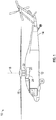
FIG. 1 is an illustration of an embodiment of a rotary winged aircraft; -
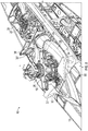
FIG. 2 is a perspective view of an embodiment of an engine inlet duct layout for a rotary winged aircraft; -
FIG. 3 is another perspective view of an embodiment of an engine inlet duct layout for a rotary winged aircraft; and -
FIG. 4 is a cross-sectional view of an embodiment of an engine inlet duct layout. - The detailed description explains embodiments of the invention, together with advantages and features, by way of example with reference to the drawings.
- Shown in
FIG. 1 is a schematic view of an embodiment of a rotary wing aircraft, in this embodiment ahelicopter 10. Thehelicopter 10 includes anairframe 12 with an extendingtail 14. Arotor assembly 16 is located at theairframe 12 and rotates about amain rotor axis 18. Themain rotor assembly 16 is driven by anengine 20 via agearbox 22. To supply airflow to theengine 20, anair inlet duct 24 is provided to direct the airflow to an engine inlet (FIG. 4 ). - Referring to
FIG. 2 , theinlet duct 24 is bifurcated, withduct legs 28 each extending from an inlet opening 30 at each lateral side of theairframe 12 to asingle duct outlet 32 at theengine 20. Theinlet duct 24 extends through a portion of theairframe 12 referred to as a main rotor pylon (MRP) 34. The MRP 34 houses thegearbox 22 for themain rotor assembly 16, which is operably connected to theengine 20. Theinlet duct 24 is bifurcated at least in part to route theinlet duct 24 around thegearbox 22 and themain rotor assembly 16. The MRP 34 is bounded longitudinally by theinlet openings 30 and anengine compartment firewall 36 separating the MRP 34 from anengine compartment 38 at which theengine 20 is located. - Referring to
FIG. 3 , eachduct leg 28 may be segmented, having aforward segment 40 extending from the inlet opening 30, for example to amidspan point 42, and arear segment 44 extending from themidspan point 42 to theduct outlet 32. Theforward segment 40 is joined to therear segment 44 at themidspan point 42 by, for example, a plurality of mechanical fasteners (not shown) with a seal or gasket to seal between theforward segment 40 and therear segment 44 to prevent leakage into and/or out of theinlet duct 24 at themidspan point 42. Segmenting theduct legs 28 increases ease of installation of theinlet duct 24, particularly ofinlet ducts 24 having long spans, and also allows for inspection of theinlet duct 24 interior by removal of one of the segments. Theduct legs 28 are fixed at theinlet openings 30 with mechanical fasteners, such asscrews 46, with a gasket (not shown) to seal between the inlet opening 30 and theduct leg 28 to prevent airflow leakage. - Referring now to
FIG. 4 , theengine 20 is connected to thegearbox 22 by a rotatingengine shaft 48, with theinlet duct 24 surrounding theengine shaft 48. In cross-section, as shown inFIG. 4 , theinlet duct 24 has a radiallyinboard leg 50 and a radiallyoutboard leg 52, relative to an engine shaft axis 54. Theinlet duct 24 extends into theengine compartment 38 through a firewall opening 56 in thefirewall 36. Theinlet duct 24 has a floating interface with theengine 20 and terminates forward of and is not fixedly secured thereto. The radiallyinboard leg 50 is sealed to ashaft support 58 through which theengine shaft 48 passes, via aninboard gasket 62, and the radiallyoutboard leg 52 is sealed to the engine firewall via anoutboard bulb seal 66. These twoseals firewall 36 from the forward compartment into theengine 20. Further, aflexible bellows 70 is provided in theengine compartment 38. Thebellows 70 is formed from a high-temperature/fire tolerant material such as titanium. Thebellows 70 extends circumferentially around theinlet duct 24 radially outboard of the radiallyoutboard leg 52 and extends from an engine compartment side of thefirewall 36 to afront frame 72 of theengine 20. The bellows 70 provides a flexible seal between thefirewall 36 and theengine 20 to prevent engine compartment air from being ingested into theengine inlet 60 via any gaps between theinlet duct 24 and theengine inlet 60. Similarly, thebellows 70 prevents leakage of inlet duct airflow into theengine compartment 38. Leakage of inlet duct air into theengine compartment 38 and/or ingestion of high temperature engine compartment airflow into theengine inlet 60, reduces engine performance and results in a reduction of power. - The floating installation of the
inlet duct 24 at theengine 20 prevents installation issues resulting from manufacturing or assembly tolerance stackup issues between the various components. Further, the installation scheme reduces stresses on theinlet duct 24 or theengine 20 resulting fromairframe 12 deflection during operation of thehelicopter 10. Further, the floating interface increases ease of installation of theinlet duct 24, as the installation location at theengine inlet 60 is often difficult to access with installation tools. - While the invention has been described in detail in connection with only a limited number of embodiments, it should be readily understood that the invention is not limited to such disclosed embodiments. Rather, the invention can be modified to incorporate any number of variations, alterations, substitutions or equivalent arrangements not heretofore described, but which are commensurate with the scope of the claims. Additionally, while various embodiments of the invention have been described, it is to be understood that aspects of the invention may include only some of the described embodiments. Accordingly, the invention is not to be seen as limited by the foregoing description, but is only limited by the scope of the appended claims.
Claims (9)
- A rotary winged aircraft (10), comprising:an airframe (12);a main rotor assembly (16);an engine (20) disposed at the airframe (12) and operably connected to the main rotor assembly (16) to drive the main rotor assembly (16);a firewall (36) through which an inlet duct (24) can extend into an engine compartment (38) of the aircraft (10); andan engine inlet assembly comprising:the inlet duct (24) which includes a first inlet duct leg (28,50) and a second inlet duct leg (28,52), the first inlet duct leg and the second inlet duct leg extending toward a common inlet duct outlet (32) disposed at an engine inlet;wherein the first inlet duct leg and the second inlet duct leg are fixedly secured to the airframe (12) of the aircraft (10) at an air inlet,wherein the inlet duct (24) extends through an opening (56) in the firewall (36) into an engine compartment (38) of the aircraft (10),wherein the inlet duct outlet (32) has a floating interface with the engine inlet and the inlet duct (24) is configured to direct an airflow to the engine inlet, andwherein the firewall (36) has an airtight seal to the engine inlet radially outboard on the inlet duct (24) via a flexible bellows seal (70) to prevent ingestion of an engine compartment (38) airflow into the engine inlet.
- The aircraft of claim 1, wherein the engine inlet assembly further comprises a bulb seal (66) disposed at the firewall (36) to seal between an exterior of the inlet duct (24) and a firewall opening (56).
- The aircraft of claim 2, wherein the inlet duct (24) is partially supported by the bulb seal (66) at the firewall (36).
- The aircraft of claim 1, wherein the inlet duct (24) at least partially surrounds an engine shaft (48) and is sealed with a gasket (62) to a shaft support (58) to seal at the interior of the inlet duct (24).
- The aircraft of claim 1, wherein each inlet duct leg (28, 50, 52) is segmented between the air inlet and the duct outlet (32).
- The aircraft of claim 1, wherein the inlet duct (24) at least partially surrounds and is sealed to an engine shaft (48) support connecting the engine (20) to the main rotor assembly (16).
- The aircraft or claim 2, wherein the inlet duct is partially supported by the bulb seal (66) disposed at the firewall (36).
- The aircraft of claim 1, wherein each inlet duct leg (28, 50, 52) is segmented between the air inlet and the duct outlet (32).
- The aircraft of claim 1, wherein the first inlet duct leg (50) and the second inlet duct leg (52) are disposed at opposing sides of the main rotor assembly (16).
Applications Claiming Priority (2)
| Application Number | Priority Date | Filing Date | Title |
|---|---|---|---|
| US14/252,236 US9586692B2 (en) | 2014-04-14 | 2014-04-14 | Engine inlet configuration |
| PCT/US2015/025507 WO2015160679A1 (en) | 2014-04-14 | 2015-04-13 | Engine inlet configuration |
Publications (3)
| Publication Number | Publication Date |
|---|---|
| EP3131817A1 EP3131817A1 (en) | 2017-02-22 |
| EP3131817A4 EP3131817A4 (en) | 2018-01-03 |
| EP3131817B1 true EP3131817B1 (en) | 2020-06-03 |
Family
ID=54264464
Family Applications (1)
| Application Number | Title | Priority Date | Filing Date |
|---|---|---|---|
| EP15779782.0A Active EP3131817B1 (en) | 2014-04-14 | 2015-04-13 | Engine inlet configuration |
Country Status (3)
| Country | Link |
|---|---|
| US (1) | US9586692B2 (en) |
| EP (1) | EP3131817B1 (en) |
| WO (1) | WO2015160679A1 (en) |
Families Citing this family (10)
| Publication number | Priority date | Publication date | Assignee | Title |
|---|---|---|---|---|
| US9574497B2 (en) * | 2013-10-08 | 2017-02-21 | Bell Helicopter Textron Inc. | Engine mounted inlet plenum for a rotorcraft |
| US9656760B2 (en) * | 2013-11-07 | 2017-05-23 | Sikorsky Aircraft Corporation | Variable geometry helicopter engine inlet |
| EP3001021B1 (en) * | 2014-09-25 | 2020-06-24 | United Technologies Corporation | Hail screen in the inlet of a conduit to a heat exhanger of an aircraft engine |
| US11130009B2 (en) * | 2016-11-04 | 2021-09-28 | Textron Innovations Inc. | Rotorcraft fall restraint protection attach points and mechanism systems |
| US10723474B2 (en) * | 2017-05-24 | 2020-07-28 | Sikorsky Aircraft Corporation | Variable geometry engine inlet for high speed aircraft |
| US10689126B2 (en) * | 2017-06-19 | 2020-06-23 | Bell Helicopter Textron Inc. | Two-piece firewall and inlet plenum |
| US11359544B2 (en) | 2017-11-10 | 2022-06-14 | Donaldson Company, Inc. | Airflow control system and methods thereof |
| US10823289B2 (en) * | 2017-11-17 | 2020-11-03 | Bell Helicopter Textron Inc. | Floating ducts |
| US10669038B2 (en) * | 2018-04-20 | 2020-06-02 | Textron Innovations Inc. | Engine inlet system with integral firewall seal |
| EP4071046B1 (en) * | 2021-04-09 | 2023-06-07 | AIRBUS HELICOPTERS DEUTSCHLAND GmbH | A rotary wing aircraft with a firewall arrangement |
Family Cites Families (13)
| Publication number | Priority date | Publication date | Assignee | Title |
|---|---|---|---|---|
| US2503172A (en) | 1942-08-17 | 1950-04-04 | Cierva Autogiro Co Ltd | Helicopter with jet reaction for counteracting torque |
| US5433070A (en) * | 1993-09-08 | 1995-07-18 | United Technologies Corporation | Flexible engine inlet duct mounting system |
| FR2748553B1 (en) | 1996-05-09 | 1998-06-19 | Snecma | INJECTION SYSTEM WITH VARIABLE GEOMETRY ADOPTING AIR FLOW ACCORDING TO ENGINE RPM |
| GB2339242B (en) | 1998-07-06 | 2001-01-24 | Richard Adkins | Intake shields |
| US6499285B1 (en) * | 2001-08-01 | 2002-12-31 | Rolls-Royce Corporation | Particle separator for a gas turbine engine |
| GB0312457D0 (en) | 2003-05-30 | 2003-07-09 | Polymer Sealing Solutions Ltd | Fireproof seal |
| US6990798B2 (en) * | 2004-04-14 | 2006-01-31 | Pratt & Whitney Corp. | Hybrid inlet |
| US7192462B2 (en) * | 2004-04-14 | 2007-03-20 | Aerospace Filtration Systems, Inc. | Engine air filter and sealing system |
| GB0702592D0 (en) | 2007-02-10 | 2007-03-21 | Unilever Plc | Sampler and method of sampling |
| DE102008017962B4 (en) * | 2008-04-08 | 2012-09-06 | Eurocopter Deutschland Gmbh | Apparatus for supplying combustion air to an engine of an aircraft |
| PL2133265T3 (en) * | 2008-06-10 | 2011-01-31 | Agusta Spa | Helicopter |
| CA2830938C (en) * | 2011-04-28 | 2015-03-24 | Bell Helicopter Textron Inc. | Self-aligning inlet plenum system for rotorcraft |
| US9234460B2 (en) | 2012-05-22 | 2016-01-12 | Sikorsky Aircraft Corporation | Engine inlet |
-
2014
- 2014-04-14 US US14/252,236 patent/US9586692B2/en active Active
-
2015
- 2015-04-13 WO PCT/US2015/025507 patent/WO2015160679A1/en active Application Filing
- 2015-04-13 EP EP15779782.0A patent/EP3131817B1/en active Active
Non-Patent Citations (1)
| Title |
|---|
| None * |
Also Published As
| Publication number | Publication date |
|---|---|
| US9586692B2 (en) | 2017-03-07 |
| WO2015160679A1 (en) | 2015-10-22 |
| EP3131817A4 (en) | 2018-01-03 |
| EP3131817A1 (en) | 2017-02-22 |
| US20150291288A1 (en) | 2015-10-15 |
Similar Documents
| Publication | Publication Date | Title |
|---|---|---|
| EP3131817B1 (en) | Engine inlet configuration | |
| EP3333403B1 (en) | Boundary layer excitation aft fan gas turbine engine | |
| US7526921B2 (en) | Auxiliary power unit with integral firebox | |
| US8777164B2 (en) | Air intake structure for an aircraft nacelle | |
| US9404507B2 (en) | Inner cowl structure for aircraft turbine engine | |
| EP2860113B1 (en) | Engine mounted inlet plenum for a rotorcraft | |
| EP3026224B1 (en) | Non-metallic engine case inlet compression seal for a gas turbine engine | |
| US7624942B2 (en) | Decoupled ducting for twin-engine reaction rotor drive | |
| US10634050B2 (en) | Air circulation device for a turbomachine comprising a hot air bypass system to a heat exchanger | |
| US20160258358A1 (en) | High turning angle ejector cooled turbine engine exhaust duct | |
| EP3401222B1 (en) | Engine exhaust duct mounting assembly | |
| EP2932068B1 (en) | Gas turbine engine with cooling scheme for drive gear system and pitch control | |
| US11118513B2 (en) | Bolted duct joints | |
| EP3670347B1 (en) | Anti-ice double walled duct system | |
| EP3705403B1 (en) | Inlet anti-ice double walled duct with supply line seal | |
| US10018048B2 (en) | T-shaped platform leading edge anti-rotation tabs | |
| US9540109B2 (en) | Turbomachine comprising a device for the cooling of a pylon | |
| US20120023967A1 (en) | Auxiliary power unit with hot section fire enclosure arrangement | |
| US11085328B2 (en) | Assembly for sealing an annular gap between an inner structure and an outer structure | |
| EP3241754B1 (en) | Bleed air duct assembly with flexible end fittings | |
| EP3620617B1 (en) | Core case heating for gas turbine engines | |
| US9963999B2 (en) | Aircraft propulsion assembly | |
| US11772783B2 (en) | Turbine engine secondary ejector system | |
| US10633107B2 (en) | Inlet seal for a turboshaft engine | |
| EP4411116A1 (en) | Buffer air system for a bearing compartment of a gas turbine |
Legal Events
| Date | Code | Title | Description |
|---|---|---|---|
| STAA | Information on the status of an ep patent application or granted ep patent |
Free format text: STATUS: THE INTERNATIONAL PUBLICATION HAS BEEN MADE |
|
| PUAI | Public reference made under article 153(3) epc to a published international application that has entered the european phase |
Free format text: ORIGINAL CODE: 0009012 |
|
| STAA | Information on the status of an ep patent application or granted ep patent |
Free format text: STATUS: REQUEST FOR EXAMINATION WAS MADE |
|
| 17P | Request for examination filed |
Effective date: 20161111 |
|
| AK | Designated contracting states |
Kind code of ref document: A1 Designated state(s): AL AT BE BG CH CY CZ DE DK EE ES FI FR GB GR HR HU IE IS IT LI LT LU LV MC MK MT NL NO PL PT RO RS SE SI SK SM TR |
|
| AX | Request for extension of the european patent |
Extension state: BA ME |
|
| DAV | Request for validation of the european patent (deleted) | ||
| DAX | Request for extension of the european patent (deleted) | ||
| RIN1 | Information on inventor provided before grant (corrected) |
Inventor name: BOFILL, STEVEN Inventor name: CHASEN, SCOTT A. Inventor name: LAMB, DONALD WILLIAM JR. Inventor name: SIMONETTI, JOSEPH LAWRENCE |
|
| A4 | Supplementary search report drawn up and despatched |
Effective date: 20171130 |
|
| RIC1 | Information provided on ipc code assigned before grant |
Ipc: B64D 33/02 20060101AFI20171124BHEP |
|
| STAA | Information on the status of an ep patent application or granted ep patent |
Free format text: STATUS: EXAMINATION IS IN PROGRESS |
|
| 17Q | First examination report despatched |
Effective date: 20190211 |
|
| GRAP | Despatch of communication of intention to grant a patent |
Free format text: ORIGINAL CODE: EPIDOSNIGR1 |
|
| STAA | Information on the status of an ep patent application or granted ep patent |
Free format text: STATUS: GRANT OF PATENT IS INTENDED |
|
| INTG | Intention to grant announced |
Effective date: 20191107 |
|
| GRAS | Grant fee paid |
Free format text: ORIGINAL CODE: EPIDOSNIGR3 |
|
| GRAA | (expected) grant |
Free format text: ORIGINAL CODE: 0009210 |
|
| STAA | Information on the status of an ep patent application or granted ep patent |
Free format text: STATUS: THE PATENT HAS BEEN GRANTED |
|
| AK | Designated contracting states |
Kind code of ref document: B1 Designated state(s): AL AT BE BG CH CY CZ DE DK EE ES FI FR GB GR HR HU IE IS IT LI LT LU LV MC MK MT NL NO PL PT RO RS SE SI SK SM TR |
|
| REG | Reference to a national code |
Ref country code: GB Ref legal event code: FG4D |
|
| REG | Reference to a national code |
Ref country code: CH Ref legal event code: EP Ref country code: AT Ref legal event code: REF Ref document number: 1276773 Country of ref document: AT Kind code of ref document: T Effective date: 20200615 |
|
| REG | Reference to a national code |
Ref country code: DE Ref legal event code: R096 Ref document number: 602015053809 Country of ref document: DE |
|
| REG | Reference to a national code |
Ref country code: LT Ref legal event code: MG4D |
|
| PG25 | Lapsed in a contracting state [announced via postgrant information from national office to epo] |
Ref country code: NO Free format text: LAPSE BECAUSE OF FAILURE TO SUBMIT A TRANSLATION OF THE DESCRIPTION OR TO PAY THE FEE WITHIN THE PRESCRIBED TIME-LIMIT Effective date: 20200903 Ref country code: GR Free format text: LAPSE BECAUSE OF FAILURE TO SUBMIT A TRANSLATION OF THE DESCRIPTION OR TO PAY THE FEE WITHIN THE PRESCRIBED TIME-LIMIT Effective date: 20200904 Ref country code: LT Free format text: LAPSE BECAUSE OF FAILURE TO SUBMIT A TRANSLATION OF THE DESCRIPTION OR TO PAY THE FEE WITHIN THE PRESCRIBED TIME-LIMIT Effective date: 20200603 Ref country code: SE Free format text: LAPSE BECAUSE OF FAILURE TO SUBMIT A TRANSLATION OF THE DESCRIPTION OR TO PAY THE FEE WITHIN THE PRESCRIBED TIME-LIMIT Effective date: 20200603 Ref country code: FI Free format text: LAPSE BECAUSE OF FAILURE TO SUBMIT A TRANSLATION OF THE DESCRIPTION OR TO PAY THE FEE WITHIN THE PRESCRIBED TIME-LIMIT Effective date: 20200603 |
|
| REG | Reference to a national code |
Ref country code: NL Ref legal event code: MP Effective date: 20200603 |
|
| PG25 | Lapsed in a contracting state [announced via postgrant information from national office to epo] |
Ref country code: HR Free format text: LAPSE BECAUSE OF FAILURE TO SUBMIT A TRANSLATION OF THE DESCRIPTION OR TO PAY THE FEE WITHIN THE PRESCRIBED TIME-LIMIT Effective date: 20200603 Ref country code: LV Free format text: LAPSE BECAUSE OF FAILURE TO SUBMIT A TRANSLATION OF THE DESCRIPTION OR TO PAY THE FEE WITHIN THE PRESCRIBED TIME-LIMIT Effective date: 20200603 Ref country code: RS Free format text: LAPSE BECAUSE OF FAILURE TO SUBMIT A TRANSLATION OF THE DESCRIPTION OR TO PAY THE FEE WITHIN THE PRESCRIBED TIME-LIMIT Effective date: 20200603 Ref country code: BG Free format text: LAPSE BECAUSE OF FAILURE TO SUBMIT A TRANSLATION OF THE DESCRIPTION OR TO PAY THE FEE WITHIN THE PRESCRIBED TIME-LIMIT Effective date: 20200903 |
|
| REG | Reference to a national code |
Ref country code: AT Ref legal event code: MK05 Ref document number: 1276773 Country of ref document: AT Kind code of ref document: T Effective date: 20200603 |
|
| PG25 | Lapsed in a contracting state [announced via postgrant information from national office to epo] |
Ref country code: AL Free format text: LAPSE BECAUSE OF FAILURE TO SUBMIT A TRANSLATION OF THE DESCRIPTION OR TO PAY THE FEE WITHIN THE PRESCRIBED TIME-LIMIT Effective date: 20200603 Ref country code: NL Free format text: LAPSE BECAUSE OF FAILURE TO SUBMIT A TRANSLATION OF THE DESCRIPTION OR TO PAY THE FEE WITHIN THE PRESCRIBED TIME-LIMIT Effective date: 20200603 |
|
| PG25 | Lapsed in a contracting state [announced via postgrant information from national office to epo] |
Ref country code: AT Free format text: LAPSE BECAUSE OF FAILURE TO SUBMIT A TRANSLATION OF THE DESCRIPTION OR TO PAY THE FEE WITHIN THE PRESCRIBED TIME-LIMIT Effective date: 20200603 Ref country code: ES Free format text: LAPSE BECAUSE OF FAILURE TO SUBMIT A TRANSLATION OF THE DESCRIPTION OR TO PAY THE FEE WITHIN THE PRESCRIBED TIME-LIMIT Effective date: 20200603 Ref country code: CZ Free format text: LAPSE BECAUSE OF FAILURE TO SUBMIT A TRANSLATION OF THE DESCRIPTION OR TO PAY THE FEE WITHIN THE PRESCRIBED TIME-LIMIT Effective date: 20200603 Ref country code: PT Free format text: LAPSE BECAUSE OF FAILURE TO SUBMIT A TRANSLATION OF THE DESCRIPTION OR TO PAY THE FEE WITHIN THE PRESCRIBED TIME-LIMIT Effective date: 20201006 Ref country code: RO Free format text: LAPSE BECAUSE OF FAILURE TO SUBMIT A TRANSLATION OF THE DESCRIPTION OR TO PAY THE FEE WITHIN THE PRESCRIBED TIME-LIMIT Effective date: 20200603 Ref country code: SM Free format text: LAPSE BECAUSE OF FAILURE TO SUBMIT A TRANSLATION OF THE DESCRIPTION OR TO PAY THE FEE WITHIN THE PRESCRIBED TIME-LIMIT Effective date: 20200603 Ref country code: EE Free format text: LAPSE BECAUSE OF FAILURE TO SUBMIT A TRANSLATION OF THE DESCRIPTION OR TO PAY THE FEE WITHIN THE PRESCRIBED TIME-LIMIT Effective date: 20200603 Ref country code: IT Free format text: LAPSE BECAUSE OF FAILURE TO SUBMIT A TRANSLATION OF THE DESCRIPTION OR TO PAY THE FEE WITHIN THE PRESCRIBED TIME-LIMIT Effective date: 20200603 |
|
| PG25 | Lapsed in a contracting state [announced via postgrant information from national office to epo] |
Ref country code: SK Free format text: LAPSE BECAUSE OF FAILURE TO SUBMIT A TRANSLATION OF THE DESCRIPTION OR TO PAY THE FEE WITHIN THE PRESCRIBED TIME-LIMIT Effective date: 20200603 Ref country code: PL Free format text: LAPSE BECAUSE OF FAILURE TO SUBMIT A TRANSLATION OF THE DESCRIPTION OR TO PAY THE FEE WITHIN THE PRESCRIBED TIME-LIMIT Effective date: 20200603 Ref country code: IS Free format text: LAPSE BECAUSE OF FAILURE TO SUBMIT A TRANSLATION OF THE DESCRIPTION OR TO PAY THE FEE WITHIN THE PRESCRIBED TIME-LIMIT Effective date: 20201003 |
|
| REG | Reference to a national code |
Ref country code: DE Ref legal event code: R097 Ref document number: 602015053809 Country of ref document: DE |
|
| PLBE | No opposition filed within time limit |
Free format text: ORIGINAL CODE: 0009261 |
|
| STAA | Information on the status of an ep patent application or granted ep patent |
Free format text: STATUS: NO OPPOSITION FILED WITHIN TIME LIMIT |
|
| PG25 | Lapsed in a contracting state [announced via postgrant information from national office to epo] |
Ref country code: DK Free format text: LAPSE BECAUSE OF FAILURE TO SUBMIT A TRANSLATION OF THE DESCRIPTION OR TO PAY THE FEE WITHIN THE PRESCRIBED TIME-LIMIT Effective date: 20200603 |
|
| 26N | No opposition filed |
Effective date: 20210304 |
|
| PG25 | Lapsed in a contracting state [announced via postgrant information from national office to epo] |
Ref country code: SI Free format text: LAPSE BECAUSE OF FAILURE TO SUBMIT A TRANSLATION OF THE DESCRIPTION OR TO PAY THE FEE WITHIN THE PRESCRIBED TIME-LIMIT Effective date: 20200603 |
|
| PG25 | Lapsed in a contracting state [announced via postgrant information from national office to epo] |
Ref country code: MC Free format text: LAPSE BECAUSE OF FAILURE TO SUBMIT A TRANSLATION OF THE DESCRIPTION OR TO PAY THE FEE WITHIN THE PRESCRIBED TIME-LIMIT Effective date: 20200603 |
|
| PG25 | Lapsed in a contracting state [announced via postgrant information from national office to epo] |
Ref country code: LU Free format text: LAPSE BECAUSE OF NON-PAYMENT OF DUE FEES Effective date: 20210413 |
|
| REG | Reference to a national code |
Ref country code: BE Ref legal event code: MM Effective date: 20210430 |
|
| PG25 | Lapsed in a contracting state [announced via postgrant information from national office to epo] |
Ref country code: LI Free format text: LAPSE BECAUSE OF NON-PAYMENT OF DUE FEES Effective date: 20210430 Ref country code: CH Free format text: LAPSE BECAUSE OF NON-PAYMENT OF DUE FEES Effective date: 20210430 |
|
| PG25 | Lapsed in a contracting state [announced via postgrant information from national office to epo] |
Ref country code: IE Free format text: LAPSE BECAUSE OF NON-PAYMENT OF DUE FEES Effective date: 20210413 |
|
| PG25 | Lapsed in a contracting state [announced via postgrant information from national office to epo] |
Ref country code: IS Free format text: LAPSE BECAUSE OF FAILURE TO SUBMIT A TRANSLATION OF THE DESCRIPTION OR TO PAY THE FEE WITHIN THE PRESCRIBED TIME-LIMIT Effective date: 20201003 |
|
| PG25 | Lapsed in a contracting state [announced via postgrant information from national office to epo] |
Ref country code: BE Free format text: LAPSE BECAUSE OF NON-PAYMENT OF DUE FEES Effective date: 20210430 |
|
| PG25 | Lapsed in a contracting state [announced via postgrant information from national office to epo] |
Ref country code: HU Free format text: LAPSE BECAUSE OF FAILURE TO SUBMIT A TRANSLATION OF THE DESCRIPTION OR TO PAY THE FEE WITHIN THE PRESCRIBED TIME-LIMIT; INVALID AB INITIO Effective date: 20150413 |
|
| P01 | Opt-out of the competence of the unified patent court (upc) registered |
Effective date: 20230520 |
|
| PG25 | Lapsed in a contracting state [announced via postgrant information from national office to epo] |
Ref country code: CY Free format text: LAPSE BECAUSE OF FAILURE TO SUBMIT A TRANSLATION OF THE DESCRIPTION OR TO PAY THE FEE WITHIN THE PRESCRIBED TIME-LIMIT Effective date: 20200603 |
|
| PG25 | Lapsed in a contracting state [announced via postgrant information from national office to epo] |
Ref country code: MK Free format text: LAPSE BECAUSE OF FAILURE TO SUBMIT A TRANSLATION OF THE DESCRIPTION OR TO PAY THE FEE WITHIN THE PRESCRIBED TIME-LIMIT Effective date: 20200603 |
|
| PGFP | Annual fee paid to national office [announced via postgrant information from national office to epo] |
Ref country code: GB Payment date: 20240429 Year of fee payment: 10 |
|
| PGFP | Annual fee paid to national office [announced via postgrant information from national office to epo] |
Ref country code: DE Payment date: 20240429 Year of fee payment: 10 |
|
| PGFP | Annual fee paid to national office [announced via postgrant information from national office to epo] |
Ref country code: FR Payment date: 20240425 Year of fee payment: 10 |