EP3736165B1 - Dual mode collector - Google Patents
Dual mode collector Download PDFInfo
- Publication number
- EP3736165B1 EP3736165B1 EP19214022.6A EP19214022A EP3736165B1 EP 3736165 B1 EP3736165 B1 EP 3736165B1 EP 19214022 A EP19214022 A EP 19214022A EP 3736165 B1 EP3736165 B1 EP 3736165B1
- Authority
- EP
- European Patent Office
- Prior art keywords
- current collector
- fluid communication
- rod lock
- inlet port
- shoe
- Prior art date
- Legal status (The legal status is an assumption and is not a legal conclusion. Google has not performed a legal analysis and makes no representation as to the accuracy of the status listed.)
- Active
Links
Images






Classifications
-
- B—PERFORMING OPERATIONS; TRANSPORTING
- B60—VEHICLES IN GENERAL
- B60L—PROPULSION OF ELECTRICALLY-PROPELLED VEHICLES; SUPPLYING ELECTRIC POWER FOR AUXILIARY EQUIPMENT OF ELECTRICALLY-PROPELLED VEHICLES; ELECTRODYNAMIC BRAKE SYSTEMS FOR VEHICLES IN GENERAL; MAGNETIC SUSPENSION OR LEVITATION FOR VEHICLES; MONITORING OPERATING VARIABLES OF ELECTRICALLY-PROPELLED VEHICLES; ELECTRIC SAFETY DEVICES FOR ELECTRICALLY-PROPELLED VEHICLES
- B60L5/00—Current collectors for power supply lines of electrically-propelled vehicles
- B60L5/38—Current collectors for power supply lines of electrically-propelled vehicles for collecting current from conductor rails
- B60L5/39—Current collectors for power supply lines of electrically-propelled vehicles for collecting current from conductor rails from third rail
-
- B—PERFORMING OPERATIONS; TRANSPORTING
- B60—VEHICLES IN GENERAL
- B60L—PROPULSION OF ELECTRICALLY-PROPELLED VEHICLES; SUPPLYING ELECTRIC POWER FOR AUXILIARY EQUIPMENT OF ELECTRICALLY-PROPELLED VEHICLES; ELECTRODYNAMIC BRAKE SYSTEMS FOR VEHICLES IN GENERAL; MAGNETIC SUSPENSION OR LEVITATION FOR VEHICLES; MONITORING OPERATING VARIABLES OF ELECTRICALLY-PROPELLED VEHICLES; ELECTRIC SAFETY DEVICES FOR ELECTRICALLY-PROPELLED VEHICLES
- B60L2200/00—Type of vehicles
- B60L2200/26—Rail vehicles
Definitions
- the present invention relates generally to a current collecting device for an electrically powered rail vehicle.
- the present invention relates to a dual mode collector for use with multiple types and mounting arrangement of electrified rails.
- Some forms of electrically powered rail vehicles receive power/current from an electrified rail, commonly referred to as a "third rail", generally located alongside the two wheel- riding rails of the vehicle track beside the vehicle.
- the rail vehicle is equipped with one or more current collecting devices which contact and receive electrical power/current from the third rail.
- the electrical power/current received from the third rail is used to power the motors and other electrified systems of the rail vehicle.
- Current collecting devices for communicating electrical current/power to a rail vehicle may be mounted in a variety of ways, such as directly to the frame of the rail vehicle or to the axle-bearing housing.
- An example of a known current collecting device for a rail vehicle is described in U.S. Patent No. 3,740,498 to Herbert .
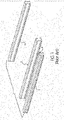
- FIGS. I and 2 show sections of a vehicle track system I having wheel rails 2 on which the wheels of an electric rail vehicle ride.
- the third rail 3 is situated alongside and generally parallel with the wheel rails 2.
- the third rail 3 is shown positioned outside the wheel rails 2, although in some systems the third rail 3 may be positioned between the wheel rails 2.
- the third rail 3 is a conductor which is supplied electricity by a power source (not shown).
- a contact surface 4 is exposed such that a conductive device, such as a current collecting device for a rail vehicle (not shown), may contact the contact surface 4 to receive electrical current/power from the third rail 3.
- the third rail 3 may be oriented such that the contact surface 4 faces upward, as shown in FIG. 1 , or downward, as shown in FIG. 2 .
- a shortcoming of known collecting devices is that such devices are configured only for one specific orientation of the third rail.
- the collecting device must be installed on the rail vehicle with foreknowledge of the orientation of the third rail of the track system on which the rail vehicle will be used. If the rail vehicle is later used on a track system having a different orientation of the third rail, the collecting devices must be either remounted on the rail vehicle in a different orientation or replaced with a different collecting device.
- a dual mode current collector including a mounting frame for attachment to a rail vehicle, the mounting frame including a plurality of legs and a pivot shaft extending between the plurality of legs along a pivot axis.
- a first current collector includes a first housing pivotally connected to the pivot shaft of the mounting frame, a first shoe arm connected to the first housing, and a first shoe attached to the first shoe arm. The first shoe has at least one conductor surface configured to engage a top side of an over-running rail.
- a second current collector includes a second housing pivotally connected to the pivot shaft of the mounting frame, a second shoe arm connected to the second housing, and a second shoe attached to the second shoe arm.
- the second shoe has at least one conductor surface configured to engage an underside of an under-running rail.
- a first actuator connected to the mounting frame and to the first current collector is configured to rotate the first current collector about the pivot axis.
- a second actuator connected to the mounting frame and to the second current collector is configured to rotate the second current collector about the pivotaxis.
- the first current collector is configured to rotate about the pivot axis independently of the second current collector.
- each of the first shoe and the second shoe has an upper conductor surface and a lower conductor surface.
- At least one of the first actuator and the second actuator includes a pneumatic cylinder.
- the pneumatic cylinder includes a rod lock configured to engage a rod of the pneumatic cylinder to prevent extension and retraction of the rod.
- the pneumatic cylinder is mounted to the mounting frame and to the first housing such that extension of the pneumatic cylinder raises the first current collector away from the over-running rail and retraction of the pneumatic cylinder lowers the first current collector toward the over-running rail.
- the pneumatic cylinder is mounted to the mounting frame and to the second housing such that extension of the pneumatic cylinder raises the second current collector towards the under-running rail and retraction of the pneumatic cylinder lowers the second current collector away from the under-running rail.
- the first current collector further includes a torsion element connecting the first shoe arm to the first housing, the torsion element permitting radial deflection of the first shoe arm relative to the first housing.
- the torsion element has a polygonal outer surface, and the torsion element is disposed in a polygonal bore of the shoe arm.
- the torsion element is connected to the first housing via an arm pivot shaft rotationally fixable relative to the first housing.
- the arm pivot shaft is vertically adjustable within a slot defined in the first housing.
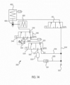
- the rod lock is implemented in a pneumatic circuit.
- the pneumatic circuit includes an air source and a rod lock dump valve.
- the rod lock dump valve has a first inlet port in fluid communication with the air source, an outlet port in fluid communication with the rod lock, an exhaust port in fluid communication with atmospheric pressure, and a solenoid configured to switch the rod lock dump valve between a first state in which the first inlet port is in fluid communication with the outlet port and a second state in which the outlet port is in fluid communication with the exhaust port.
- the pneumatic circuit further includes a pressure switch configured to detect air pressure received at the first inlet port and, based on the pressure detected, actuate the solenoid to switch the rod lock dump valve between the first state and the second state. With the rod lock dump valve in the second state, the rod lock is configured to engage the rod of the pneumatic cylinder.
- the pneumatic circuit further includes a rod lock override control valve having a first inlet port in fluid communication with the air source, a second inlet port in fluid communication with a reservoir, an outlet port in fluid communication with the first inlet port of the rod lock dump valve, and a solenoid configured to switch the rod lock override control valve between a first state in which the first inlet port is in fluid communication with the outlet port and a second state in which the second inlet port is in fluid communication with the outlet port.
- a rod lock override control valve having a first inlet port in fluid communication with the air source, a second inlet port in fluid communication with a reservoir, an outlet port in fluid communication with the first inlet port of the rod lock dump valve, and a solenoid configured to switch the rod lock override control valve between a first state in which the first inlet port is in fluid communication with the outlet port and a second state in which the second inlet port is in fluid communication with the outlet port.
- the rod lock is implemented in apneumatic circuit.
- the pneumatic circuit includes an air source and a shuttle valve having an inlet port in fluid communication with the air source, an outlet port in fluid communication with the rod lock, an exhaust port in fluid communication with atmospheric pressure, and a sliding element moveable between a first position and a second position based on air pressure received at the inlet port.
- the inlet port In the first position of the sliding element, the inlet port is in fluid communication with the outlet port and the exhaust port is isolated.
- the outlet port In the second position of the sliding element, the outlet port is in fluid communication with the exhaust port and the inlet port is isolated. With the sliding element in the second position, the rod lock is configured to engage the rod of the pneumatic cylinder.
- the pneumatic circuit further includes a rod lock override control valve having a first inlet port in fluid communication with the air source, a second inlet port in fluid communication with a reservoir, an outlet port in fluid communication with the inlet port of the shuttle valve, and a solenoid configured to switch the rod lock override control valve between a first state in which the first inlet port is in fluid communication with the outlet port and a second state in which the second inlet port is in fluid communication with the outlet port.
- a rod lock override control valve having a first inlet port in fluid communication with the air source, a second inlet port in fluid communication with a reservoir, an outlet port in fluid communication with the inlet port of the shuttle valve, and a solenoid configured to switch the rod lock override control valve between a first state in which the first inlet port is in fluid communication with the outlet port and a second state in which the second inlet port is in fluid communication with the outlet port.
- the term "at least one of is synonymous with "one or more of.
- the phrase "at least one of A, B, and C” means any one of A, B, and C, or any combination of any two or more of A, B, and C.
- "at least one of A, B, and C” includes one or more of A alone; or one or more B alone; or one or more of C alone; or one or more of A and one or more of B; or one or more of A and one or more of C; or one or more of Band one or more of C; or one or more of all of A, B, and C.
- the term "at least two of is synonymous with "two or more of.
- the phrase "at least two of D, E, and F” means any combination of any two or more of D, E, and F.
- “at least two of D, E, and F” includes one or more of D and one or more of E; or one or more of D and one or more of F; or one or more of E and one or more of F; or one or more of all of D, E, and F.
- third rail refers to a stationary, electrified structure of a rail vehicle track system from which a rail vehicle may receive electrical current/power.
- a third rail is a continuous or semi-continuous conductor which generally runs alongside the wheel-supporting rails of an electric rail vehicle track system.
- the present invention generally relates to a current collecting device for an electrically powered rail vehicle.
- the present invention relates to a dual mode collector for use with multiple types and mounting arrangements of the third rail.
- a non-limiting embodiment of a current collecting device 1000 for a rail vehicle in accordance with the principles of the present invention generally includes a mounting frame 200 and a plurality of collectors 300, namely, a first collector 300a and a second collector 300b.
- the mounting frame 200 may include one or more attachment brackets 210 and/or other suitable structures for rigidly affixing the current collecting device 1000 to a rail vehicle (not shown).
- the mounting frame 200 may further include one or more legs 220 which define a pivot axis A, along which the plurality of collectors 300 may be rotatably mounted.
- a collector pivot shaft 230 may extend through the one or more legs 220 along the pivot axis A.
- Each of the collectors 300a, 300b may be connected to the mounting frame 200 via the collector pivot shaft 230 such that the collectors 300a, 300b are independently rotatable relative to the mounting frame 200 and relative to one another.
- the collector pivot shaft 230 may be connected to the mounting frame 200 via one or more pivot shaft bearings 240 which permit rotation of the collector pivot shaft 230 relative to the mounting frame 200.
- Each of the pivot shaft bearings 240 may include a roller bearing, a ball bearing, a bushing, or a like component for facilitating rotation of the collector pivot shaft 230 relative to the legs 220 of the mounting frame 200.
- the pivot shaft bearings 240 may be omitted and the collector pivot shaft 230 may be rigidly connected to the legs 220 of the mounting frame 200.
- Each of the collectors 300a, 300b is independently rotatable relative to the collector pivot shaft 230 such the collectors may be assume different positions relative to one another as will be described herein.
- the current collecting device 1000 may further include one or more actuators, such as pneumatic cylinders 400, respectively mounted to each of the collectors 300a, 300b, and to the mounting frame 200.
- a first end 402 of each pneumatic cylinder 400 may be connected to the mounting frame 200, and a second end 404 of each pneumatic cylinder 400 may be connected to one of the collectors 300.
- Each of the pneumatic cylinders 400 may be actuated to rotate the collector 300a, 300b to which the pneumatic cylinder 400 is attached relative to the mounting frame 200 about the pivot axis A.
- Each collector 300 includes a housing 310 rotatably connectable to the collector pivot shaft 230 of the mounting frame 200.
- the housing 310 may include two plate members 312, each having an aperture therein through which the collector pivot shaft 230 extends.
- the housing 310 of each collector 300 further includes a cylinder tab 318 to which the second end 404 of the pneumatic cylinder 400 may be attached.
- Each collector 300 further includes a shoe arm 320 having a first end 322 and a second end 324.
- a contact shoe 330 configured to engage the third rail 910, 920 (see FIGS.
- the contact shoe 330 may be mounted to the first end 322 of the shoe arm 320.
- the contact shoe 330 may have an upper conductor surface 332 and a lower conductor surface 334 each configured to engage and slide along the third rail 910, 920.
- the contact shoe 330 is typically a wear component requiring periodic replacement, and as such, the contact shoe 330 may be removably mounted to the first end 322 of the shoe arm 320.
- the contact shoe 330 is connected to one or more conductor cables 336. Electrical current/power is transmitted from the third rail 910, 920, through the contact shoe 330 and the one or more conductor cables 336, and to the motors and other electrical systems of the rail vehicle.
- the second end 324 of the shoe arm 320 may be mounted to the housing 310 by an arm pivot shaft 326 extending through a slot 314 in each of the plate members 312.
- the slot 314 of each plate member 312 has a major axis having a length greater than the diameter of the arm pivot shaft 326 to allow vertical adjustment of the pivot shaft 326 relative to the housing 310.
- a shaft collar 340 may be mounted to each end of the arm pivot shaft 326 to set the vertical position of the arm pivot shaft 326 within the slots 314 and to rotationally fix the arm pivot shaft 326 relative to the housing 310.
- Each shaft collar 340 may have one or more teeth 342 having a complementary profile to the teeth 316 of the plate members 312.
- the shaft collars 340 are slid onto the respective ends of the arm pivot shaft 326 such that the teeth 342 of the shaft collars 340 engage at a desired position with the plurality of teeth 316 of the plate member 312. Engagement of the plurality of teeth 316 of the plate members 312 with the one or more teeth 342 of the shaft collars 340 prevents vertical movement of shaft collars 340 and, consequently, vertical movement of the arm pivot shaft 326 within the slots 314.
- one or both of the shaft collars 340 may include a clamp which rotationally locks the shaft collar 340 to the arm pivot shaft 326.
- the clamp may include a split ring 344 and an adjustable screw 346.
- the adjustable screw 346 may be tightened to squeeze the arm pivot shaft 326 within the split ring 344, frictionally locking the arm pivot shaft 326 to the shaft collar 340.
- the arm pivot shaft 326 Prior to tightening the adjustable screw 346, the arm pivot shaft 326 may be rotated to locate the shoe arm 320 at a desired position relative to the housing 310. The adjustable screw 346 may then be tightened to lock the arm pivot shaft 326 in place relative to the housing 310.
- the second end 324 of the shoe arm 320 may be elastically mounted to the housing 310 and the arm pivot shaft 326 via a torsion element, such as a center-bonded bushing 350 as shown in FIG. 9 .
- a torsion element such as a center-bonded bushing 350 as shown in FIG. 9 .
- An outer housing 352 of the center-bonded bushing 350 may have a polygonal or substantially polygonal cross section, such as a square cross section with filleted corners as shown in the non-limiting embodiment of FIG. 9 .
- the second end 324 of the shoe arm 320 is shown transparently so that the connection between the center-bonded bushing 350 and shoe arm 320 may be appreciated.
- the center-bonded bushing 350 includes an internal sleeve 354 having a polygonal or substantially polygonal bore 356, such as a hexagonal bore shown in the non-limiting embodiment of FIG. 9 .
- the internal sleeve 354 is joined to the outer housing 352 by an elastomer block 358 configured to allow controlled rotational deflection of the internal sleeve 354 relative to the outer housing 352 under a torsional load. More particularly, rotating the internal sleeve 354 relative to the outer housing 352 generates a progressively higher spring force within the elastomer block 358, which biases the center-bonded bushing 350 back to a relaxed state once the torsional load is removed.
- the second end 324 of the shoe arm 320 may have a polygonal bore 328 shaped to receive the outer housing 352 of the center-bonded bushing 350.
- the polygonal shapes of the outer housing 352 and the bore 328 of the shoe arm 320 prevent rotation of the outer housing 352 relative to the shoe arm 320.
- the arm pivot shaft 326 may have a polygonal cross section, such as a hexagonal cross section as shown in FIGS. 8 , 10 , and 11 , corresponding to the polygonal bore 356 of the internal sleeve 354 of the center-bonded bushing 350.
- the polygonal shapes of the arm pivot shaft 326 and the bore 356 of the internal sleeve 354 prevent rotation of the arm pivot shaft 326 relative to the internal sleeve 354.
- the arm pivot shaft 326 may be rotationally fixed to the internal sleeve 354 of the center-bonded bushing 350 in other manners known in the art.
- the arm pivot shaft 326 and the internal sleeve 354 may have corresponding keyways for receiving a key which prevents rotation of the arm pivot shaft 326 relative to the internal sleeve 354.
- the current collecting device 1000 may be configured to selectively drive one of the first collector 300a and the second collector 300b into engagement with the third rail 910, 920, depending on the orientation of the third rail 910, 920.
- the first collector 300a is configured to engage an over-running third rail 910
- the second collector 300b is configured to engage an under-running third rail 920.
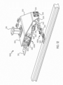
- FIG. 12 shows a non-limiting embodiment of the current collecting device 1000 in use on a rail track system having an over-running third rail 912.
- the pneumatic cylinder 400 connected to the first collector 300a may be actuated in a first direction to rotate the first collector 300a about the pivot axis A such that the lower conductor surface 334 of the contact shoe 330 of the first collector 300a engages a contact surface 912 of the over-running first third rail 910.
- the pneumatic cylinder 400 connected to the second collector 300b may be actuated in a second direction to rotate the second collector 300b about the pivot axis A such that the contact shoe 330 of the second collector 300b is out of contact with the over-running third rail 910.
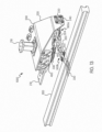
- FIG. 13 shows a non-limiting embodiment of the current collecting device 1000 in use on a rail track system having an under-running third rail 920.
- the pneumatic cylinder 400 connected to the first collector 300a may be actuated in a third direction, opposite the first direction, to rotate the first collector 300a about the pivot axis A such that the contact shoe 330 of the first collector 300a is out of contact with the under-running third rail 920.
- the pneumatic cylinder 400 connected to the second collector 300b may be actuated in a fourth direction, opposite the second direction, to rotate the second collector 300b about the pivot axis A such that the upper conductor surface of the contact shoe 330 of the second collector 300b engages a contact surface 922 of the under-running third rail 920.
- the current collector device 1000 may be used to change which of the one or more collectors 300a, 300b is in contact with the third rail 910, 920 depending on the orientation (i.e., over-running or under-running) of the third rail 910, 920.
- the distance between the third rails 910, 920 and the mounting frame 200, which is rigidly attached to the railcar, is unlikely to be constant over any substantial length of track.
- uneven wear of components, and discontinuities in the third rail 910, 912 can all cause variance in the distance between the third rail 910, 912 and the mounting frame 200 over a given length of the third rail 910, 920.
- the collectors 300a, 300b may be calibrated to suit the height of the third rail 910, 920 by adjusting the position of the arm pivot shaft 326 within the slots 314 and by adjusting the rotation of the arm pivot shaft 326 relative to the shaft collars 340. These adjustment processes are described above with reference to FIGS. 8-11 .
- the collectors 300a, 300b may be particularly calibrated such that the center-bonded bushing 350 is in a preloaded state when the contact shoe 330 engages the third rails 910, 920.
- the internal sleeve 354 of the center-bonded bushing 350 is rotated relative to the outer housing 352 such that a spring force is stored in the elastomer block 358.
- the center-bonded bushing 350 is maintained in the preloaded state until the contact shoe 330 separates from the third rail 910, 920, at which point the shoe arm 320 is permitted to radially deflect as the spring force stored in the elastomer block 358 is released.
- the first collector 300a is shown engaged with the over- running third rail 910 with the center-bonded bushing 350 in the preloaded state. If the distance between the third rail 910 and the mounting frame 200 increases, the shoe arm 320 radially deflects in a downward direction along with the third rail 910 as the center-bonded bushing 350 is released from the preloaded state. Thus, the contact shoe 330 remains in contact with the third rail 910 despite the change in distance between the third rail 910 and the mounting frame 200. Conversely, if the distance between the third rail 910 and the mounting frame 200 decreases, the center-bonded bushing 350 permits the shoe arm 320 to deflect in an upward direction along with the third rail 910. Thus, the contact shoe 330 remains in contact with the third rail 910 despite the change in distance between the third rail 910 and the mounting frame 200.
- the second collector 300b is shown engaged with the under-running third rail 920 with the center-bonded bushing 350 in the preloaded state. If the distance between the third rail 920 and the mounting frame 200 decreases, the shoe arm 320 radially deflects in an upward direction along with the third rail 920 as the center-bonded bushing 350 is released from the preloaded state. Thus, the contact shoe 330 remains in contact with the third rail 920 despite the change in distance between the third rail 920 and the mounting frame 200. Conversely, if the distance between the third rail 920 and the mounting frame 200 increases, the center-bonded bushing 350 permits the shoe arm 320 to deflect in a downward direction along with the third rail 920. Thus, the contact shoe 330 remains in contact with the third rail 920 despite the change in distance between the third rail 920 and the mounting frame 200.
- the pneumatic cylinder 400 connected to the first collector 300a is retracted to drive the first collector 300a into engagement with the over-running third rail 910.
- the pneumatic cylinder 400 connected to the second collector 300b is extended to drive the second collector 300b into engagement with the under-running third rail 920.
- the pneumatic cylinder 400 connected to the second collector 300b may be equipped with a rod lock 420, of any design known in the art, capable of holding the rod 406 of the cylinder in the extended position in the event that the air source to the pneumatic cylinder 400 fails.
- a rod lock 420 is particularly desirable on the pneumatic cylinder 400 connected to the second collector 300b because unintended retraction of the rod 406 due to a loss of air pressure may cause the shoe arm 320 to drop out of contact with the under-running third rail 920.
- the rod lock 420 may be implemented in a pneumatic circuit 500 controlling either or both of the pneumatic cylinders 400.
- the pneumatic circuit 500 may include an air source 502 which supplies air to the pneumatic circuit 500.
- the air source 502 may be, for example, a compressor onboard the rail vehicle.
- the air source 502 supplies air to three paths.
- a first path 504 runs from the air source 502 to a cylinder control valve 510 which, in turn, is connected to the pneumatic cylinder 400.
- the cylinder control valve 510 may be any suitable valve known in the art for controlling a pneumatic cylinder.
- the cylinder control valve 510 is switchable between a first state which causes the rod 406 of the pneumatic cylinder 400 to extend, and a second state which causes the rod 406 of the pneumatic cylinder 400 to retract.
- the second path 506 supplied with air from the air source 502 runs directly to a first inlet port 521 of the rod lock override control valve 520.
- the third path 508 supplied with air from the air source 502 runs to a reservoir 530 which connects to a second inlet port 522 of the rod lock override control valve 520.
- An outlet port 523 of the rod lock override control valve 520 is connected to a first inlet port 541 of a rod lock dump valve 540, which in turn is connected to the rod lock 420.
- the rod lock override control valve 520 is switchable between a first state (as shown in FIG. 14 ) in which the first inlet port 521 is in fluid communication with the outlet port 523, and a second state in which the second inlet port 522 is in fluid communication with the outlet port 523.
- the rod lock override control valve 520 may be switched between the first state and second state by, for example, a solenoid 524 connected to a processor of a control unit (not shown) of the rail vehicle.
- the outlet port 523 of the rod lock override control valve 520 is connected to the first inlet port 541 of the rod lock dump valve 540.
- the rod lock dump valve 540 is switchable between a first state and a second state. In the first state, the first inlet port 541 is in fluid communication with the rod lock 420 via an outlet port 542 of the rod lock dump valve 540. In the second state (shown in FIG. 14 ), the outlet port 542 of the rod lock dump valve 540 is in fluid communication with an exhaust port 543.
- the rod lock dump valve 540 may be switched between the first state and the second state by a solenoid 544 activated by a pressure switch 550 in fluid communication with the outlet port 523 of the rod lock override control valve 520.
- the rod lock pneumatic circuit 500 is configured to control operation of the rod lock 420, particularly in the event of a failure of the air source 502.
- the pressure switch 550 detects air pressure at the outlet port 523 of the rod lock override control valve 520. If the detected air pressure is below a predetermined value, indicating a failure of the air source 502, the pressure switch 550 activates the solenoid 544 to switch the rod lock dump valve 540 to the second state in which the outlet port 542 of the rod lock dump valve 540 is in fluid communication with an exhaust port 543. As such, the rod lock 420, which is in fluid communication with the outlet port 542 of the rod lock dump valve 540, is vented to atmospheric pressure.
- the rod lock 420 detects the absence of air pressure and automatically engages the rod 406 of the pneumatic cylinder 400 to prevent extension/retraction of the rod 406. In this manner, the collector 300, controlled by the pneumatic cylinder 400 equipped with the rod lock 420, is prevented from disengaging the third rail 910, 920 in the event of failure of the air source 502.
- the pressure switch 550 detects failure of the air source 502 as soon as the air pressure (or lack thereof) propagates through the second path 506 and the rod lock override control valve 520.
- the pressure switch 550 switches the rod lock dump valve 540 back to the first state, such that the rod lock 420 is in fluid communication with the rod lock override control valve 520, and the rod lock 420 is automatically deactivated.
- the rod lock override control valve 520 If the rod lock override control valve 520 is switched to the second state in which the outlet port 523 is in fluid communication with the second inlet port 522, activation of the rod lock 420 is delayed due the presence of the reservoir 530 between the air source 502 and the pressure switch 550. That is, in the event of failure of the air source 502, the reservoir 530 maintains air pressure at the rod lock override control valve 520 above the predetermined value at which the pressure switch 550 activates the solenoid 544, at least for a limited time.
- a check valve 531 isolates the reservoir 530 and the remaining downstream components from losing air pressure back through the failed air source 502.
- the rod lock 420 remains deactivated until the air pressure detected by pressure switch 550 drops below the predetermined value at which the pressure switch 550 activates the solenoid 544.
- the rod 406 of the pneumatic cylinder 400 is thus not held in position, as the air source 502 is not supplying air pressure to the cylinder 400 and the rod lock 420 is deactivated.
- the pneumatic cylinder 400 may be equipped with a spring-extend feature, as known in the art, which biases the rod 406 of the pneumatic cylinder 400 toward the extended position when no air is supplied to the cylinder 400. As the rod 406 extends due to the spring-extend feature, the collector 300 is raised.
- the rod lock dump valve 540 is switched to the second state, activating the rod lock 420 to hold the rod 406 of the pneumatic cylinder 400 in the now-extended position.
- the pressure switch 550 switches the rod lock dump valve 540 back to the first state, such that the rod lock 420 is in fluid communication with the rod lock override control valve 520, and the rod lock 420 is automatically deactivated. Restoration of the air source 502 also causes the cylinder control valve 510 to retract the pneumatic cylinder 400.
- FIG. 15 Another non-limiting embodiment of the rod lock pneumatic circuit 500 is shown in FIG. 15 .
- the embodiment of FIG. 15 is similar to the embodiment of FIG. 14 , except that the rod lock dump valve 540 and the pressure switch 550 are replaced by a shuttle valve 560. Only the differences between the embodiments of FIGS. 14 and 15 will be discussed in detail.
- the shuttle valve 560 has an inlet port 561 connected to the outlet port 523 of the rod lock override control valve 520, an outlet port 562 connected to the rod lock 420, and an exhaust port 563 connected to atmospheric pressure.
- the shuttle valve 560 may be a conventional shuttle valve as known in the art.
- a pressure-responsive sliding element 564 such as a spring-biased ball or slug, is moveable within the shuttle valve 560 to regulate fluid communication between the inlet port 561, the outlet port 562, and the exhaust port 563. If air pressure above a predetermined threshold is received at the first inlet port 561, the sliding element 564 moves to a first position allowing fluid communication between the first inlet port 561 and the outlet port 562, while isolating the exhaust port 562 from the inlet port 561 and the outlet port 562.
- the sliding element 564 moves to a second position allowing fluid communication between the exhaust port 563 and the outlet port 562, while isolating the inlet port 561 from the exhaust port 563 and the outlet port 562.
- the shuttle valve 560 behaves in substantially the same manner as the rod lock dump valve 540 and the pressure switch 550 of FIG. 14 . If air pressure received at the inlet port 561 is below the predetermined threshold, indicating a failure of the air source 502, the rod lock 420, which is in fluid communication with the outlet port 542 of the rod lock dump valve 540, is vented to atmospheric pressure via the exhaust port 563. The rod lock 420 detects the absence of air pressure and automatically engages the rod 406 of the pneumatic cylinder 400 to prevent extension/retraction of the rod 406. In this manner, the collector 300, controlled by the pneumatic cylinder 400 equipped with the rod lock 420 is prevented from disengaging the third rail 910, 920 in the event of failure of the air source 502. The rod lock override valve 520 functions in the same manner as in the embodiment of FIG. 14 .
- the particular mounting arrangement and operation of the pneumatic cylinders 400 relative to the mounting frame and the collectors 300a, 300b is not to be construed as limiting.
- extension of the pneumatic cylinders 400 causes the collectors 300a, 300b to rotate upward
- retraction of the pneumatic cylinders 400 causes the collectors 300a, 300b to rotate downward.
- the cylinder tab 318 of one or both collectors 300a, 300b may be relocated to the opposite side of the collector pivot shaft 230 such that the pneumatic cylinder 400 is retracted to drive the collectors 300a, 300b upward and extended to drive the collectors downward.
- the first end 402 of one or both of the pneumatic cylinders 400 may be relocated to the opposite side of the collector pivot shaft 230 such that the pneumatic cylinder 400 is retracted to drive the collectors 300a, 300b upward and extended to drive the collectors downward.
- FIG. 16 another non-limiting embodiment of a current collecting device 1000 is shown.
- the current collecting device 1000 of FIG. 15 is substantially identical to the embodiment shown in FIG. 3 except for changes to the layout of the mounting frame 200.
- pneumatic cylinders 400 represent only a non-limiting embodiment of the present invention, and other non-limiting embodiments may utilize hydraulic cylinders, linear actuators, or like components in place of the pneumatic cylinders 400 to achieve the functionality described herein.
- electric motors or the like may be coupled to the collectors 300a, 300b and/or coupled to the collector pivot shaft 320 to rotate the collectors 300a, 300b relative to the mounting frame 200.
Landscapes
- Engineering & Computer Science (AREA)
- Power Engineering (AREA)
- Transportation (AREA)
- Mechanical Engineering (AREA)
- Current-Collector Devices For Electrically Propelled Vehicles (AREA)
Description
- The present invention relates generally to a current collecting device for an electrically powered rail vehicle. In particular, the present invention relates to a dual mode collector for use with multiple types and mounting arrangement of electrified rails.
- Some forms of electrically powered rail vehicles receive power/current from an electrified rail, commonly referred to as a "third rail", generally located alongside the two wheel- riding rails of the vehicle track beside the vehicle. The rail vehicle is equipped with one or more current collecting devices which contact and receive electrical power/current from the third rail. The electrical power/current received from the third rail is used to power the motors and other electrified systems of the rail vehicle. Current collecting devices for communicating electrical current/power to a rail vehicle may be mounted in a variety of ways, such as directly to the frame of the rail vehicle or to the axle-bearing housing. An example of a known current collecting device for a rail vehicle is described in
U.S. Patent No. 3,740,498 to Herbert . - At least two arrangements and/or orientations of the third rail, as shown respectively in
FIGS. I and2 , are commonly used in the rail vehicle industry.FIGS. I and2 show sections of a vehicle track system I havingwheel rails 2 on which the wheels of an electric rail vehicle ride. Thethird rail 3 is situated alongside and generally parallel with thewheel rails 2. InFIGS. I and2 , thethird rail 3 is shown positioned outside thewheel rails 2, although in some systems thethird rail 3 may be positioned between thewheel rails 2. Thethird rail 3 is a conductor which is supplied electricity by a power source (not shown). Acontact surface 4 is exposed such that a conductive device, such as a current collecting device for a rail vehicle (not shown), may contact thecontact surface 4 to receive electrical current/power from thethird rail 3. For a variety of reasons, thethird rail 3 may be oriented such that thecontact surface 4 faces upward, as shown inFIG. 1 , or downward, as shown inFIG. 2 . - A shortcoming of known collecting devices, such as that taught by Herbert, is that such devices are configured only for one specific orientation of the third rail. Thus, the collecting device must be installed on the rail vehicle with foreknowledge of the orientation of the third rail of the track system on which the rail vehicle will be used. If the rail vehicle is later used on a track system having a different orientation of the third rail, the collecting devices must be either remounted on the rail vehicle in a different orientation or replaced with a different collecting device.
- One known collecting device which endeavors to overcome the aforementioned deficiencies is described in
U.S. Patent No. 8,348,035 to Sommer . However, there continues to exist a need for collecting devices which are suitable for use with multiple third-rail orientations of rail vehicle track systems Other collecting devices are known fromCN206426861U ,CN106347135A orDE102009054484 A1 . - According to the invention, as defined in the independent claim, is disclosed a dual mode current collector including a mounting frame for attachment to a rail vehicle, the mounting frame including a plurality of legs and a pivot shaft extending between the plurality of legs along a pivot axis. A first current collector includes a first housing pivotally connected to the pivot shaft of the mounting frame, a first shoe arm connected to the first housing, and a first shoe attached to the first shoe arm. The first shoe has at least one conductor surface configured to engage a top side of an over-running rail. A second current collector includes a second housing pivotally connected to the pivot shaft of the mounting frame, a second shoe arm connected to the second housing, and a second shoe attached to the second shoe arm. The second shoe has at least one conductor surface configured to engage an underside of an under-running rail. A first actuator connected to the mounting frame and to the first current collector is configured to rotate the first current collector about the pivot axis. A second actuator connected to the mounting frame and to the second current collector is configured to rotate the second current collector about the pivotaxis.
- In some non-limiting embodiments, the first current collector is configured to rotate about the pivot axis independently of the second current collector.
- In some non-limiting embodiments, each of the first shoe and the second shoe has an upper conductor surface and a lower conductor surface.
- In some non-limiting embodiments, at least one of the first actuator and the second actuator includes a pneumatic cylinder.
- In some non-limiting embodiments, the pneumatic cylinder includes a rod lock configured to engage a rod of the pneumatic cylinder to prevent extension and retraction of the rod.
- In some non-limiting embodiments, the pneumatic cylinder is mounted to the mounting frame and to the first housing such that extension of the pneumatic cylinder raises the first current collector away from the over-running rail and retraction of the pneumatic cylinder lowers the first current collector toward the over-running rail.
- In some non-limiting embodiments, the pneumatic cylinder is mounted to the mounting frame and to the second housing such that extension of the pneumatic cylinder raises the second current collector towards the under-running rail and retraction of the pneumatic cylinder lowers the second current collector away from the under-running rail.
- In some non-limiting embodiments, the first current collector further includes a torsion element connecting the first shoe arm to the first housing, the torsion element permitting radial deflection of the first shoe arm relative to the first housing.
- In some non-limiting embodiments, the torsion element has a polygonal outer surface, and the torsion element is disposed in a polygonal bore of the shoe arm.
- In some non-limiting embodiments, the torsion element is connected to the first housing via an arm pivot shaft rotationally fixable relative to the first housing.
- In some non-limiting embodiments, the arm pivot shaft is vertically adjustable within a slot defined in the first housing.
- In some non-limiting embodiments, the rod lock is implemented in a pneumatic circuit. The pneumatic circuit includes an air source and a rod lock dump valve. The rod lock dump valve has a first inlet port in fluid communication with the air source, an outlet port in fluid communication with the rod lock, an exhaust port in fluid communication with atmospheric pressure, and a solenoid configured to switch the rod lock dump valve between a first state in which the first inlet port is in fluid communication with the outlet port and a second state in which the outlet port is in fluid communication with the exhaust port. The pneumatic circuit further includes a pressure switch configured to detect air pressure received at the first inlet port and, based on the pressure detected, actuate the solenoid to switch the rod lock dump valve between the first state and the second state. With the rod lock dump valve in the second state, the rod lock is configured to engage the rod of the pneumatic cylinder.
- In some non-limiting embodiments, the pneumatic circuit further includes a rod lock override control valve having a first inlet port in fluid communication with the air source, a second inlet port in fluid communication with a reservoir, an outlet port in fluid communication with the first inlet port of the rod lock dump valve, and a solenoid configured to switch the rod lock override control valve between a first state in which the first inlet port is in fluid communication with the outlet port and a second state in which the second inlet port is in fluid communication with the outlet port.
- In some non-limiting embodiments, the rod lock is implemented in apneumatic circuit. The pneumatic circuit includes an air source and a shuttle valve having an inlet port in fluid communication with the air source, an outlet port in fluid communication with the rod lock, an exhaust port in fluid communication with atmospheric pressure, and a sliding element moveable between a first position and a second position based on air pressure received at the inlet port. In the first position of the sliding element, the inlet port is in fluid communication with the outlet port and the exhaust port is isolated. In the second position of the sliding element, the outlet port is in fluid communication with the exhaust port and the inlet port is isolated. With the sliding element in the second position, the rod lock is configured to engage the rod of the pneumatic cylinder.
- In some non-limiting embodiments, the pneumatic circuit further includes a rod lock override control valve having a first inlet port in fluid communication with the air source, a second inlet port in fluid communication with a reservoir, an outlet port in fluid communication with the inlet port of the shuttle valve, and a solenoid configured to switch the rod lock override control valve between a first state in which the first inlet port is in fluid communication with the outlet port and a second state in which the second inlet port is in fluid communication with the outlet port.
- These and other features and characteristics of the present invention, as well as the methods of operation and functions of the related elements of structures and the combination of parts and economies of manufacture, will become more apparent upon consideration of the following description and with reference to the accompanying drawings, all of which form a part of this specification, wherein like reference numerals designate corresponding parts in the various figures. It is to be expressly understood, however, that the drawings are for the purpose of illustration and description only and are not intended as a definition of the limits of the invention. As used in the specification and the claims, the singular forms of "a", "an", and "the" include plural referents unless the context clearly dictates otherwise.
-
-
FIG. 11 s a perspective view of a section of a known rail vehicle track system arrangement; -
FIG. 2 is a perspective view of a section of another known rail vehicle track system arrangement; -
FIG. 3 is a perspective view of a non-limiting embodiment of a current collecting device of the present invention; -
FIG. 4 is a front view of the current collecting device ofFIG. 3 ; -
FIG. 5 is a right side view of the current collecting device ofFIG. 3 ; -
FIG. 6 is a left side section view of the current collecting device ofFIG. 3 , as viewed from section arrows IV-IV indicated onFIG. 4 ; -
FIG. 7 is a rear view of the current collecting device ofFIG. 3 ; -
FIG. 8 is perspective view of a first collector of the current collecting device ofFIG. 3 ; -
FIG. 9 is a perspective view of a center-bonded bushing of the first collector ofFIG. 8 ; -
FIG. 10 is a perspective view of the first collector ofFIG. 8 ; -
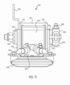
FIG. 11 is a front view of the first collector ofFIG. 10 ; -
FIG. 12 is a perspective view of the current collecting device ofFIG. 3 , with the first collector engaged with a third rail in an over-running configuration; -
FIG. 13 is a perspective view of the current collecting device ofFIG. 3 , with a second collector engaged with a third rail in an under-running configuration; -
FIG. 14 is a schematic representation of a non-limiting embodiment of a pneumatic circuit for a rod lock of the current collecting device ofFIG. 3 ; -
FIG. 15 is a schematic representation of another non-limiting embodiment of a pneumatic circuit for a rod lock of the current collecting device ofFIG. 3 ; and -
FIG. 16 is a perspective view of another non-limiting embodiment of a current collecting device of the present invention. - For purposes of the description hereinafter, the terms "end", "upper", "lower", "right", "left", "vertical", "horizontal", "top", "bottom", "lateral", "longitudinal", and derivatives thereof shall relate to the invention as it is oriented in the drawing figures. However, it is to be understood that the invention may assume various alternative variations and step sequences, except where expressly specified to the contrary. It is also to be understood that the specific devices and processes illustrated in the attached drawings and described in the following specification are simply exemplary embodiments or aspects of the invention. Hence, specific dimensions and other physical characteristics related to the embodiments or aspects disclosed herein are not to be considered as limiting.
- As used herein, the term "at least one of is synonymous with "one or more of. For example, the phrase "at least one of A, B, and C" means any one of A, B, and C, or any combination of any two or more of A, B, and C. For example, "at least one of A, B, and C" includes one or more of A alone; or one or more B alone; or one or more of C alone; or one or more of A and one or more of B; or one or more of A and one or more of C; or one or more of Band one or more of C; or one or more of all of A, B, and C. Similarly, as used herein, the term "at least two of is synonymous with "two or more of. For example, the phrase "at least two of D, E, and F" means any combination of any two or more of D, E, and F. For example, "at least two of D, E, and F" includes one or more of D and one or more of E; or one or more of D and one or more of F; or one or more of E and one or more of F; or one or more of all of D, E, and F.
- As used herein, the term "third rail" refers to a stationary, electrified structure of a rail vehicle track system from which a rail vehicle may receive electrical current/power. A third rail is a continuous or semi-continuous conductor which generally runs alongside the wheel-supporting rails of an electric rail vehicle track system.
- The present invention generally relates to a current collecting device for an electrically powered rail vehicle. In particular, the present invention relates to a dual mode collector for use with multiple types and mounting arrangements of the third rail. With reference to
FIGS. 3-7 , a non-limiting embodiment of acurrent collecting device 1000 for a rail vehicle in accordance with the principles of the present invention generally includes a mountingframe 200 and a plurality ofcollectors 300, namely, afirst collector 300a and asecond collector 300b. The mountingframe 200 may include one ormore attachment brackets 210 and/or other suitable structures for rigidly affixing thecurrent collecting device 1000 to a rail vehicle (not shown). The mountingframe 200 may further include one ormore legs 220 which define a pivot axis A, along which the plurality ofcollectors 300 may be rotatably mounted. Acollector pivot shaft 230 may extend through the one ormore legs 220 along the pivot axis A. - Each of the
collectors frame 200 via thecollector pivot shaft 230 such that thecollectors frame 200 and relative to one another. In a non-limiting embodiment, thecollector pivot shaft 230 may be connected to the mountingframe 200 via one or morepivot shaft bearings 240 which permit rotation of thecollector pivot shaft 230 relative to the mountingframe 200. Each of thepivot shaft bearings 240 may include a roller bearing, a ball bearing, a bushing, or a like component for facilitating rotation of thecollector pivot shaft 230 relative to thelegs 220 of the mountingframe 200. In other non-limiting embodiments, thepivot shaft bearings 240 may be omitted and thecollector pivot shaft 230 may be rigidly connected to thelegs 220 of the mountingframe 200. Each of thecollectors collector pivot shaft 230 such the collectors may be assume different positions relative to one another as will be described herein. - The
current collecting device 1000 may further include one or more actuators, such aspneumatic cylinders 400, respectively mounted to each of thecollectors frame 200. Afirst end 402 of eachpneumatic cylinder 400 may be connected to the mountingframe 200, and asecond end 404 of eachpneumatic cylinder 400 may be connected to one of thecollectors 300. Each of thepneumatic cylinders 400 may be actuated to rotate thecollector pneumatic cylinder 400 is attached relative to the mountingframe 200 about the pivot axis A. - Referring now to
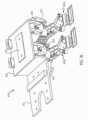
FIGS. 8-11 , acollector 300, which may be either thefirst collector 300a or thesecond collector 300b, will now be described in greater detail. Eachcollector 300 includes ahousing 310 rotatably connectable to thecollector pivot shaft 230 of the mountingframe 200. In some non-limiting embodiments, thehousing 310 may include twoplate members 312, each having an aperture therein through which thecollector pivot shaft 230 extends. Thehousing 310 of eachcollector 300 further includes acylinder tab 318 to which thesecond end 404 of thepneumatic cylinder 400 may be attached. Eachcollector 300 further includes ashoe arm 320 having afirst end 322 and asecond end 324. Acontact shoe 330 configured to engage the third rail 910, 920 (seeFIGS. 12 and13 ) may be mounted to thefirst end 322 of theshoe arm 320. Thecontact shoe 330 may have anupper conductor surface 332 and alower conductor surface 334 each configured to engage and slide along thethird rail 910, 920. Thecontact shoe 330 is typically a wear component requiring periodic replacement, and as such, thecontact shoe 330 may be removably mounted to thefirst end 322 of theshoe arm 320. Thecontact shoe 330 is connected to one ormore conductor cables 336. Electrical current/power is transmitted from thethird rail 910, 920, through thecontact shoe 330 and the one ormore conductor cables 336, and to the motors and other electrical systems of the rail vehicle. - The
second end 324 of theshoe arm 320 may be mounted to thehousing 310 by anarm pivot shaft 326 extending through aslot 314 in each of theplate members 312. Theslot 314 of eachplate member 312 has a major axis having a length greater than the diameter of thearm pivot shaft 326 to allow vertical adjustment of thepivot shaft 326 relative to thehousing 310. A plurality ofteeth 316, each extending in a direction generally perpendicular to the major axis of theslot 314, surrounds theslot 314 in each of theplate members 312. Ashaft collar 340 may be mounted to each end of thearm pivot shaft 326 to set the vertical position of thearm pivot shaft 326 within theslots 314 and to rotationally fix thearm pivot shaft 326 relative to thehousing 310. Eachshaft collar 340 may have one ormore teeth 342 having a complementary profile to theteeth 316 of theplate members 312. To set the location of thearm pivot shaft 326 within theslots 314, theshaft collars 340 are slid onto the respective ends of thearm pivot shaft 326 such that theteeth 342 of theshaft collars 340 engage at a desired position with the plurality ofteeth 316 of theplate member 312. Engagement of the plurality ofteeth 316 of theplate members 312 with the one ormore teeth 342 of theshaft collars 340 prevents vertical movement ofshaft collars 340 and, consequently, vertical movement of thearm pivot shaft 326 within theslots 314. - To rotationally fix the
arm pivot shaft 326 relative to thehousing 310, one or both of theshaft collars 340 may include a clamp which rotationally locks theshaft collar 340 to thearm pivot shaft 326. In the non-limiting embodiment shown inFIGS. 8-11 , the clamp may include asplit ring 344 and anadjustable screw 346. Theadjustable screw 346 may be tightened to squeeze thearm pivot shaft 326 within thesplit ring 344, frictionally locking thearm pivot shaft 326 to theshaft collar 340. Prior to tightening theadjustable screw 346, thearm pivot shaft 326 may be rotated to locate theshoe arm 320 at a desired position relative to thehousing 310. Theadjustable screw 346 may then be tightened to lock thearm pivot shaft 326 in place relative to thehousing 310. - In some non-limiting embodiments, the
second end 324 of theshoe arm 320 may be elastically mounted to thehousing 310 and thearm pivot shaft 326 via a torsion element, such as a center-bondedbushing 350 as shown inFIG. 9 . Anouter housing 352 of the center-bondedbushing 350 may have a polygonal or substantially polygonal cross section, such as a square cross section with filleted corners as shown in the non-limiting embodiment ofFIG. 9 . Referring back toFIG. 8 , thesecond end 324 of theshoe arm 320 is shown transparently so that the connection between the center-bondedbushing 350 andshoe arm 320 may be appreciated. The center-bondedbushing 350 includes aninternal sleeve 354 having a polygonal or substantiallypolygonal bore 356, such as a hexagonal bore shown in the non-limiting embodiment ofFIG. 9 . Theinternal sleeve 354 is joined to theouter housing 352 by anelastomer block 358 configured to allow controlled rotational deflection of theinternal sleeve 354 relative to theouter housing 352 under a torsional load. More particularly, rotating theinternal sleeve 354 relative to theouter housing 352 generates a progressively higher spring force within theelastomer block 358, which biases the center-bondedbushing 350 back to a relaxed state once the torsional load is removed. - The
second end 324 of theshoe arm 320 may have a polygonal bore 328 shaped to receive theouter housing 352 of the center-bondedbushing 350. The polygonal shapes of theouter housing 352 and the bore 328 of theshoe arm 320 prevent rotation of theouter housing 352 relative to theshoe arm 320. Similarly, thearm pivot shaft 326 may have a polygonal cross section, such as a hexagonal cross section as shown inFIGS. 8 ,10 , and11 , corresponding to thepolygonal bore 356 of theinternal sleeve 354 of the center-bondedbushing 350. The polygonal shapes of thearm pivot shaft 326 and thebore 356 of theinternal sleeve 354 prevent rotation of thearm pivot shaft 326 relative to theinternal sleeve 354. In other non-limiting embodiments, thearm pivot shaft 326 may be rotationally fixed to theinternal sleeve 354 of the center-bondedbushing 350 in other manners known in the art. For example, thearm pivot shaft 326 and theinternal sleeve 354 may have corresponding keyways for receiving a key which prevents rotation of thearm pivot shaft 326 relative to theinternal sleeve 354. - With the center-bonded
bushing 350 connected to theshoe arm 320 and thearm pivot shaft 326, rotation of theshoe arm 320 relative to thehousing 310 is limited to the controlled rotation permitted by theelastomer block 358 of the center-bondedbushing 350 when a load is applied to theshoe arm 320. To adjust the unloaded position of theshoe arm 320 relative to thehousing 310, theadjustable screw 346 of theshaft collar 340 may be loosened, thearm pivot shaft 326 may be rotated to the desired position, and theadjustable screw 346 may be retightened, locking thearm pivot shaft 326 in thesplit ring 344. - Referring no to
FIGS. 12-13 , thecurrent collecting device 1000 may be configured to selectively drive one of thefirst collector 300a and thesecond collector 300b into engagement with thethird rail 910, 920, depending on the orientation of thethird rail 910, 920. In the non-limiting embodiment shown in the drawings, thefirst collector 300a is configured to engage an over-running third rail 910, and thesecond collector 300b is configured to engage an under-runningthird rail 920.FIG. 12 shows a non-limiting embodiment of thecurrent collecting device 1000 in use on a rail track system having an over-running third rail 912. To properly engage the over-running third rail 910, thepneumatic cylinder 400 connected to thefirst collector 300a may be actuated in a first direction to rotate thefirst collector 300a about the pivot axis A such that thelower conductor surface 334 of thecontact shoe 330 of thefirst collector 300a engages a contact surface 912 of the over-running first third rail 910. Thepneumatic cylinder 400 connected to thesecond collector 300b may be actuated in a second direction to rotate thesecond collector 300b about the pivot axis A such that thecontact shoe 330 of thesecond collector 300b is out of contact with the over-running third rail 910. -
FIG. 13 shows a non-limiting embodiment of thecurrent collecting device 1000 in use on a rail track system having an under-runningthird rail 920. To properly engage the under-runningthird rail 920, thepneumatic cylinder 400 connected to thefirst collector 300a may be actuated in a third direction, opposite the first direction, to rotate thefirst collector 300a about the pivot axis A such that thecontact shoe 330 of thefirst collector 300a is out of contact with the under-runningthird rail 920. Thepneumatic cylinder 400 connected to thesecond collector 300b may be actuated in a fourth direction, opposite the second direction, to rotate thesecond collector 300b about the pivot axis A such that the upper conductor surface of thecontact shoe 330 of thesecond collector 300b engages a contact surface 922 of the under-runningthird rail 920. - In the above described manner, the
current collector device 1000 may be used to change which of the one ormore collectors third rail 910, 920 depending on the orientation (i.e., over-running or under-running) of thethird rail 910, 920. - In real world track systems, the distance between the
third rails 910, 920 and the mountingframe 200, which is rigidly attached to the railcar, is unlikely to be constant over any substantial length of track. Intolerances during manufacturing and assembly of the various components of the track system, uneven wear of components, and discontinuities in the third rail 910, 912 can all cause variance in the distance between the third rail 910, 912 and the mountingframe 200 over a given length of thethird rail 910, 920. To ensure that contact is maintained between thecollectors third rail 910, 920 in spite of such variance, thecollectors third rail 910, 920 by adjusting the position of thearm pivot shaft 326 within theslots 314 and by adjusting the rotation of thearm pivot shaft 326 relative to theshaft collars 340. These adjustment processes are described above with reference toFIGS. 8-11 . Thecollectors bushing 350 is in a preloaded state when thecontact shoe 330 engages thethird rails 910, 920. In the preloaded state, theinternal sleeve 354 of the center-bondedbushing 350 is rotated relative to theouter housing 352 such that a spring force is stored in theelastomer block 358. The center-bondedbushing 350 is maintained in the preloaded state until the contact
shoe 330 separates from thethird rail 910, 920, at which point theshoe arm 320 is permitted to radially deflect as the spring force stored in theelastomer block 358 is released. - Referring back to
FIG. 12 , thefirst collector 300a is shown engaged with the over- running third rail 910 with the center-bondedbushing 350 in the preloaded state. If the distance between the third rail 910 and the mountingframe 200 increases, theshoe arm 320 radially deflects in a downward direction along with the third rail 910 as the center-bondedbushing 350 is released from the preloaded state. Thus, thecontact shoe 330 remains in contact with the third rail 910 despite the change in distance between the third rail 910 and the mountingframe 200. Conversely, if the distance between the third rail 910 and the mountingframe 200 decreases, the center-bondedbushing 350 permits theshoe arm 320 to deflect in an upward direction along with the third rail 910. Thus, thecontact shoe 330 remains in contact with the third rail 910 despite the change in distance between the third rail 910 and the mountingframe 200. - Similarly, referring again to
FIG. 13 , thesecond collector 300b is shown engaged with the under-runningthird rail 920 with the center-bondedbushing 350 in the preloaded state. If the distance between thethird rail 920 and the mountingframe 200 decreases, theshoe arm 320 radially deflects in an upward direction along with thethird rail 920 as the center-bondedbushing 350 is released from the preloaded state. Thus, thecontact shoe 330 remains in contact with thethird rail 920 despite the change in distance between thethird rail 920 and the mountingframe 200. Conversely, if the distance between thethird rail 920 and the mountingframe 200 increases, the center-bondedbushing 350 permits theshoe arm 320 to deflect in a downward direction along with thethird rail 920. Thus, thecontact shoe 330 remains in contact with thethird rail 920 despite the change in distance between thethird rail 920 and the mountingframe 200. - As may be appreciated from
FIG. 12 , thepneumatic cylinder 400 connected to thefirst collector 300a is retracted to drive thefirst collector 300a into engagement with the over-running third rail 910. Conversely, thepneumatic cylinder 400 connected to thesecond collector 300b is extended to drive thesecond collector 300b into engagement with the under-runningthird rail 920. Referring back toFIG. 7 , in some non-limiting embodiments, thepneumatic cylinder 400 connected to thesecond collector 300b may be equipped with arod lock 420, of any design known in the art, capable of holding therod 406 of the cylinder in the extended position in the event that the air source to thepneumatic cylinder 400 fails. Arod lock 420 is particularly desirable on thepneumatic cylinder 400 connected to thesecond collector 300b because unintended retraction of therod 406 due to a loss of air pressure may cause theshoe arm 320 to drop out of contact with the under-runningthird rail 920. - Referring now to
FIG. 14 , therod lock 420 may be implemented in apneumatic circuit 500 controlling either or both of thepneumatic cylinders 400. Thepneumatic circuit 500 may include anair source 502 which supplies air to thepneumatic circuit 500. Theair source 502 may be, for example, a compressor onboard the rail vehicle. Theair source 502 supplies air to three paths. Afirst path 504 runs from theair source 502 to acylinder control valve 510 which, in turn, is connected to thepneumatic cylinder 400. Thecylinder control valve 510 may be any suitable valve known in the art for controlling a pneumatic cylinder. Thecylinder control valve 510 is switchable between a first state which causes therod 406 of thepneumatic cylinder 400 to extend, and a second state which causes therod 406 of thepneumatic cylinder 400 to retract. - The
second path 506 supplied with air from theair source 502 runs directly to afirst inlet port 521 of the rod lockoverride control valve 520. Thethird path 508 supplied with air from theair source 502 runs to areservoir 530 which connects to asecond inlet port 522 of the rod lockoverride control valve 520. Anoutlet port 523 of the rod lockoverride control valve 520 is connected to afirst inlet port 541 of a rodlock dump valve 540, which in turn is connected to therod lock 420. - The rod lock
override control valve 520 is switchable between a first state (as shown inFIG. 14 ) in which thefirst inlet port 521 is in fluid communication with theoutlet port 523, and a second state in which thesecond inlet port 522 is in fluid communication with theoutlet port 523. The rod lockoverride control valve 520 may be switched between the first state and second state by, for example, asolenoid 524 connected to a processor of a control unit (not shown) of the rail vehicle. - As discussed above, the
outlet port 523 of the rod lockoverride control valve 520 is connected to thefirst inlet port 541 of the rodlock dump valve 540. The rodlock dump valve 540 is switchable between a first state and a second state. In the first state, thefirst inlet port 541 is in fluid communication with therod lock 420 via anoutlet port 542 of the rodlock dump valve 540. In the second state (shown inFIG. 14 ), theoutlet port 542 of the rodlock dump valve 540 is in fluid communication with anexhaust port 543. The rodlock dump valve 540 may be switched between the first state and the second state by asolenoid 544 activated by apressure switch 550 in fluid communication with theoutlet port 523 of the rod lockoverride control valve 520. - The rod lock
pneumatic circuit 500 is configured to control operation of therod lock 420, particularly in the event of a failure of theair source 502. Thepressure switch 550 detects air pressure at theoutlet port 523 of the rod lockoverride control valve 520. If the detected air pressure is below a predetermined value, indicating a failure of theair source 502, thepressure switch 550 activates thesolenoid 544 to switch the rodlock dump valve 540 to the second state in which theoutlet port 542 of the rodlock dump valve 540 is in fluid communication with anexhaust port 543. As such, therod lock 420, which is in fluid communication with theoutlet port 542 of the rodlock dump valve 540, is vented to atmospheric pressure. Therod lock 420 detects the absence of air pressure and automatically engages therod 406 of thepneumatic cylinder 400 to prevent extension/retraction of therod 406. In this manner, thecollector 300, controlled by thepneumatic cylinder 400 equipped with therod lock 420, is prevented from disengaging thethird rail 910, 920 in the event of failure of theair source 502. - If the rod lock
override control valve 520 is switched to the first state in which theoutlet port 523 is in fluid communication with thefirst inlet port 521, activation of therod lock 420 as described above is essentially immediate upon the failure of theair source 502. That is, because thefirst inlet port 521 is directly connected to the air source via thesecond path 506, thepressure switch 550 detects failure of theair source 502 as soon as the air pressure (or lack thereof) propagates through thesecond path 506 and the rod lockoverride control valve 520. Once air pressure returns from theair source 502, thepressure switch 550 switches the rodlock dump valve 540 back to the first state, such that therod lock 420 is in fluid communication with the rod lockoverride control valve 520, and therod lock 420 is automatically deactivated. - If the rod lock
override control valve 520 is switched to the second state in which theoutlet port 523 is in fluid communication with thesecond inlet port 522, activation of therod lock 420 is delayed due the presence of thereservoir 530 between theair source 502 and thepressure switch 550. That is, in the event of failure of theair source 502, thereservoir 530 maintains air pressure at the rod lockoverride control valve 520 above the predetermined value at which thepressure switch 550 activates thesolenoid 544, at least for a limited time. Acheck valve 531 isolates thereservoir 530 and the remaining downstream components from losing air pressure back through the failedair source 502. As thereservoir 530 gradually loses airpressure, therod lock 420 remains deactivated until the air pressure detected bypressure switch 550 drops below the predetermined value at which thepressure switch 550 activates thesolenoid 544. Therod 406 of thepneumatic cylinder 400 is thus not held in position, as theair source 502 is not supplying air pressure to thecylinder 400 and therod lock 420 is deactivated. Thepneumatic cylinder 400 may be equipped with a spring-extend feature, as known in the art, which biases therod 406 of thepneumatic cylinder 400 toward the extended position when no air is supplied to thecylinder 400. As therod 406 extends due to the spring-extend feature, thecollector 300 is raised. If the air pressure detected by thepressure switch 550 subsequently drops below the predetermined value causing the pressure switch to activate thesolenoid 544 of the rodlock dump valve 540, the rodlock dump valve 540 is switched to the second state, activating therod lock 420 to hold therod 406 of thepneumatic cylinder 400 in the now-extended position. Once air pressure returns from theair source 502, thepressure switch 550 switches the rodlock dump valve 540 back to the first state, such that therod lock 420 is in fluid communication with the rod lockoverride control valve 520, and therod lock 420 is automatically deactivated. Restoration of theair source 502 also causes thecylinder control valve 510 to retract thepneumatic cylinder 400. - Another non-limiting embodiment of the rod lock
pneumatic circuit 500 is shown inFIG. 15 . The embodiment ofFIG. 15 is similar to the embodiment ofFIG. 14 , except that the rodlock dump valve 540 and thepressure switch 550 are replaced by a shuttle valve 560. Only the differences between the embodiments ofFIGS. 14 and15 will be discussed in detail. The shuttle valve 560 has aninlet port 561 connected to theoutlet port 523 of the rod lockoverride control valve 520, anoutlet port 562 connected to therod lock 420, and anexhaust port 563 connected to atmospheric pressure. The shuttle valve 560 may be a conventional shuttle valve as known in the art. A pressure-responsive slidingelement 564, such as a spring-biased ball or slug, is moveable within the shuttle valve 560 to regulate fluid communication between theinlet port 561, theoutlet port 562, and theexhaust port 563. If air pressure above a predetermined threshold is received at thefirst inlet port 561, the slidingelement 564 moves to a first position allowing fluid communication between thefirst inlet port 561 and theoutlet port 562, while isolating theexhaust port 562 from theinlet port 561 and theoutlet port 562. If the air pressure received at theinlet port 561 is below the predetermined threshold, the slidingelement 564 moves to a second position allowing fluid communication between theexhaust port 563 and theoutlet port 562, while isolating theinlet port 561 from theexhaust port 563 and theoutlet port 562. - The shuttle valve 560 behaves in substantially the same manner as the rod
lock dump valve 540 and thepressure switch 550 ofFIG. 14 . If air pressure received at theinlet port 561 is below the predetermined threshold, indicating a failure of theair source 502, therod lock 420, which is in fluid communication with theoutlet port 542 of the rodlock dump valve 540, is vented to atmospheric pressure via theexhaust port 563. Therod lock 420 detects the absence of air pressure and automatically engages therod 406 of thepneumatic cylinder 400 to prevent extension/retraction of therod 406. In this manner, thecollector 300, controlled by thepneumatic cylinder 400 equipped with therod lock 420 is prevented from disengaging thethird rail 910, 920 in the event of failure of theair source 502. The rodlock override valve 520 functions in the same manner as in the embodiment ofFIG. 14 . - It is to be understood that the particular mounting arrangement and operation of the
pneumatic cylinders 400 relative to the mounting frame and thecollectors pneumatic cylinders 400 causes thecollectors pneumatic cylinders 400 causes thecollectors cylinder tab 318 of one or bothcollectors collector pivot shaft 230 such that thepneumatic cylinder 400 is retracted to drive thecollectors first end 402 of one or both of thepneumatic cylinders 400 may be relocated to the opposite side of thecollector pivot shaft 230 such that thepneumatic cylinder 400 is retracted to drive thecollectors - Referring now to
FIG. 16 , another non-limiting embodiment of acurrent collecting device 1000 is shown. Thecurrent collecting device 1000 ofFIG. 15 is substantially identical to the embodiment shown inFIG. 3 except for changes to the layout of the mountingframe 200. - It is to be further understood that the
pneumatic cylinders 400 represent only a non-limiting embodiment of the present invention, and other non-limiting embodiments may utilize hydraulic cylinders, linear actuators, or like components in place of thepneumatic cylinders 400 to achieve the functionality described herein. In still other non-limiting embodiments, electric motors or the like may be coupled to thecollectors collector pivot shaft 320 to rotate thecollectors frame 200. - It is to be understood that the invention may assume various alternative variations and step sequences, except where expressly specified to the contrary. It is also to be understood that the specific devices and processes illustrated in the attached drawings and described in the specification are simply exemplary embodiments or aspects of the invention. Although the invention has been described in detail for the purpose of illustration based on what are currently considered to be the most practical and preferred embodiments or aspects, it is to be understood that such detail is solely for that purpose and that the invention is not limited to the disclosed embodiments or aspects, but, on the contrary, is intended to cover modifications thereof as long as they fall within the scope of the appended claims.
Claims (15)
- A dual mode current collector (1000), comprising:a mounting frame (200) for attachment to a vehicle, the mounting frame (200) comprising a plurality of legs (220) and a pivot shaft (230) extending between the plurality of legs (220) along a pivot axis (A);a first current collector (300a), comprising:a first housing (310) pivotally connected to the pivot shaft (230) of the mounting frame (200);a first shoe arm (320) connected to the first housing (310); anda first shoe (330) attached to the first shoe arm (320), the first shoe (330) having at least one conductor surface (332, 334) configured to engage a top side of a first conductive body (910);a second current collector (300b), comprising:a second housing (310) pivotally connected to the pivot shaft (230) of the mounting frame (200);a second shoe (330) arm (320) connected to the second housing (310); anda second shoe (330) attached to the second shoe (330) arm (320), the second shoe (330) having at least one conductor surface (332, 334) configured to engage an underside of a second conductive body (920);a first actuator (400) connected to the mounting frame (200) and to the first current collector (300a), the first actuator (400) configured to rotate the first current collector (300a) about the pivot axis (A); anda second actuator (400) connected to the mounting frame (200) and to the second current collector (300b), the second actuator (400) configured to rotate the second current collector (300b) about the pivot axis (A).
- The dual mode current collector (1000) of claim 1, wherein the first current collector (300a) is configured to rotate about the pivot axis (A) independently of the second current collector (300b).
- The dual mode current collector (1000) of claim 1, wherein each of the first shoe (330) and the second shoe (330) has an upper conductor surface (332) and a lower conductor surface (334).
- The dual mode current collector (1000) of claim 1, wherein at least one of the first actuator (400) or the second actuator (400) comprises a pneumatic cylinder (400).
- The dual mode current collector (1000) of claim 4, wherein the pneumatic cylinder (400) comprises a rod lock (420) configured to engage a rod (406) of the pneumatic cylinder (400) to prevent extension and retraction of the rod (406).
- The dual mode current collector (1000) of claim 4, wherein the pneumatic cylinder (400) is mounted to the mounting frame (200) and to the first housing (310) such that extension of the pneumatic cylinder (400) raises the first current collector (300a) away from the first conductive body (910) and retraction of the pneumatic cylinder (400) lowers the first current collector (300a) toward the first conductive body (910).
- The dual mode current collector (1000) of claim 4, wherein the pneumatic cylinder (400) is mounted to the mounting frame (200) and to the second housing (310) such that extension of the pneumatic cylinder (400) raises the second current collector (300b) towards the second conductive body (920) and retraction of the pneumatic cylinder (400) lowers the second current collector (300b) away from the second conductive body (920).
- The dual mode current collector (1000) of claim 1, wherein the first current collector (300a) further comprises:
a torsion element (350) connecting the first shoe arm (320) to the first housing (310), the torsion element (350) permitting radial deflection of the first shoe arm (320) relative to the first housing (310). - The dual mode current collector (1000) of claim 8, wherein the torsion element (350) has a polygonal outer surface (352), and
wherein the torsion element (350) is disposed in a polygonal bore (328) of the first shoe arm (320). - The dual mode current collector (1000) of claim 8, wherein the torsion element (350) is connected to the first housing (310) via an arm pivot shaft (230) rotationally fixable relative to the first housing (310).
- The dual mode current collector (1000) of claim 10, wherein the arm pivot shaft (230) is vertically adjustable within a slot defined in the first housing (310).
- The dual mode current collector (1000) of claim 5, wherein the rod lock (420) is implemented in a pneumatic circuit (500) comprising:an air source (502);a rod lock dump valve (540) having a first inlet port (541) in fluid communication with the air source (502), an outlet port (542) in fluid communication with the rod lock (420), an exhaust port (543) in fluid communication with atmospheric pressure, and a solenoid (544) configured to switch the rod lock (420) dump valve between a first state in which the first inlet port (541) is in fluid communication with the outlet port (542) and a second state in which the outlet port (542) is in fluid communication with the exhaust port (543); anda pressure switch (550) configured to detect air pressure received at the first inlet port (541) and, based on the pressure detected, actuate the solenoid (544) to switch the rod lock dump valve (540) between the first state and the second state,wherein, with the rod lock dump valve (540) in the second state, the rod lock (420) is configured to engage the rod (406) of the pneumatic cylinder (400).
- The dual mode current collector (1000) of claim 12, wherein the pneumatic circuit (500) further comprises:
a rod lock override control valve (520) having a first inlet port (521) in fluid communication with the air source (502), a second inlet port (522) in fluid communication with a reservoir (530), an outlet port (523) in fluid communication with the first inlet port (541) of the rod lock dump valve (540), and a solenoid (544) configured to switch the rod lock override control valve (520) between a first state in which the first inlet port (521) is in fluid communication with the outlet port (523) and a second state in which the second inlet port (522) is in fluid communication with the outlet port (523). - The dual mode current collector (1000) of claim 5, wherein the rod lock (420) is implemented in a pneumatic circuit (500) comprising:an air source (502); anda shuttle valve (560) having an inlet port (561) in fluid communication with the air source (502), an outlet port (562) in fluid communication with the rod lock (420), an exhaust port (563) in fluid communication with atmospheric pressure, and a sliding element (564) moveable between a first position and a second position based on air pressure received at the inlet port (561);wherein in the first position of the sliding element (564), the inlet port (561) is in fluid communication with the outlet port (562) and the exhaust port (563) is isolated,wherein in the second position of the sliding element (564), the outlet port (562) is in fluid communication with the exhaust port (563) and the inlet port (561) is isolated, andwherein, with the sliding element (564) in the second position, the rod lock (420) is configured to engage the rod (406) of the pneumatic cylinder (400).
- The dual mode current collector (1000) of claim 14, wherein the pneumatic circuit (500) further comprises:
a rod lock override control valve (520) having a first inlet port (521) in fluid communication with the air source (502), a second inlet port (522) in fluid communication with a reservoir (530), an outlet port (523) in fluid communication with the inlet port (561) of the shuttle valve (560), and a solenoid (544) configured to switch the rod lock override control valve (520) between a first state in which the first inlet port (521) is in fluid communication with the outlet port (523) and a second state in which the second inlet port (522) is in fluid communication with the outlet port (523).
Applications Claiming Priority (1)
| Application Number | Priority Date | Filing Date | Title |
|---|---|---|---|
| US16/235,548 US11173791B2 (en) | 2018-12-28 | 2018-12-28 | Dual mode collector |
Publications (2)
| Publication Number | Publication Date |
|---|---|
| EP3736165A1 EP3736165A1 (en) | 2020-11-11 |
| EP3736165B1 true EP3736165B1 (en) | 2023-03-22 |
Family
ID=68808106
Family Applications (1)
| Application Number | Title | Priority Date | Filing Date |
|---|---|---|---|
| EP19214022.6A Active EP3736165B1 (en) | 2018-12-28 | 2019-12-06 | Dual mode collector |
Country Status (2)
| Country | Link |
|---|---|
| US (2) | US11173791B2 (en) |
| EP (1) | EP3736165B1 (en) |
Families Citing this family (5)
| Publication number | Priority date | Publication date | Assignee | Title |
|---|---|---|---|---|
| DE102019212826A1 (en) * | 2019-08-27 | 2021-03-04 | Siemens Mobility GmbH | Pantograph for a rail vehicle |
| EP4077025A1 (en) * | 2019-12-20 | 2022-10-26 | Schunk Transit Systems GmbH | Current collector and method for power transmission |
| CN111976496A (en) * | 2020-08-20 | 2020-11-24 | 中车株洲电力机车有限公司 | Current collector |
| US11881653B2 (en) * | 2021-11-24 | 2024-01-23 | Caterpillar Inc. | System and method for positioning a conductive rod powering a work machine |
| US12413035B2 (en) * | 2022-01-18 | 2025-09-09 | Caterpillar Global Mining Equipment Llc | Slidable current collector and method for contacting conductor rail |
Family Cites Families (10)
| Publication number | Priority date | Publication date | Assignee | Title |
|---|---|---|---|---|
| US3786762A (en) * | 1971-03-05 | 1974-01-22 | Alden Self Transit Syst | Transportation system electrical power distribution |
| US3740498A (en) | 1971-11-17 | 1973-06-19 | Ohio Brass Co | Electric current collector |
| FR2471299A1 (en) * | 1979-12-14 | 1981-06-19 | Bardet Sa Ets Andre | Trolley-bus current collector with automatic contact and retraction - by alignment of boom and collector shoe with wire, using remote controlled aiming sight |
| US6152273A (en) * | 1998-02-20 | 2000-11-28 | Magnetek, Inc. | Universal arm and mounting block for a current collector |
| WO2004069579A1 (en) * | 2003-02-03 | 2004-08-19 | Schunk Metall Und Kunststoff Gmbh | Current collector |
| US8348035B2 (en) * | 2009-12-10 | 2013-01-08 | Schunk Bahn- Und Industrietechnik Gmbh | Pressing-on device for a current collector and method for energy transmission |
| US8839921B2 (en) * | 2011-09-29 | 2014-09-23 | Schunk Bahn-Und Industrietechnik Gmbh | Pressure plate assembly and method for power transmission |
| AT516478A1 (en) * | 2014-11-05 | 2016-05-15 | Siemens Ag Oesterreich | Current collector of a rail vehicle |
| CN106347135A (en) * | 2016-11-03 | 2017-01-25 | 天津益昌电气设备有限公司 | Insulating double-boot side contact current collector |
| CN206426861U (en) * | 2016-12-29 | 2017-08-22 | 比亚迪股份有限公司 | Collector shoe and the straddle-type track train with it |
-
2018
- 2018-12-28 US US16/235,548 patent/US11173791B2/en active Active
-
2019
- 2019-12-06 EP EP19214022.6A patent/EP3736165B1/en active Active
-
2021
- 2021-10-14 US US17/501,631 patent/US11807110B2/en active Active
Also Published As
| Publication number | Publication date |
|---|---|
| US20200207211A1 (en) | 2020-07-02 |
| EP3736165A1 (en) | 2020-11-11 |
| US20220032779A1 (en) | 2022-02-03 |
| US11173791B2 (en) | 2021-11-16 |
| US11807110B2 (en) | 2023-11-07 |
Similar Documents
| Publication | Publication Date | Title |
|---|---|---|
| EP3736165B1 (en) | Dual mode collector | |
| US5018756A (en) | Control for self steering suspension assembly | |
| WO1997037864B1 (en) | Anti-creep device for a trailer with air springs | |
| EP3004680B1 (en) | Caliper body assembly | |
| US20120080245A1 (en) | Seat tilt apparatus | |
| WO2015073341A1 (en) | Land vehicle steering system including selective inboard and outboard wheels adjustment | |
| CN102695665A (en) | Trigger device for a speed governor of an elevator system | |
| CN101720291B (en) | Binary adjustment method for the angular position of the plane of a motor vehicle wheel | |
| US9004517B2 (en) | Bicycle wheel carrier assembly with built-in brake | |
| CA2292263A1 (en) | Mower comprising a centralized device for regulating the lifting force exerted on the harvesting mechanism | |
| CA2940714C (en) | Multi head windrower | |
| EP0926943A1 (en) | Lost motion lift control for a mower deck | |
| EP3575206A1 (en) | System for driving a flap arrangement between a retracted position and an extended position | |
| KR100962853B1 (en) | Rear Axle Angle Adjuster | |
| US20180272818A1 (en) | Isolated lift assembly for vehicle auxiliary suspension arrangement | |
| US6122988A (en) | Braking force distribution linkage for a manually actuated parking brake system | |
| EP2336011B1 (en) | Auxiliary drive unit for a trailer | |
| EP1867502A1 (en) | Vehicle suspension system | |
| JP2973124B2 (en) | Device for obtaining shaft load signal | |
| US9987178B2 (en) | Wheelchair braking and steering system | |
| JP2008531396A (en) | Toe active control system and method for automobile | |
| US7591087B2 (en) | Flow divider for snowplow wings | |
| WO2013056894A1 (en) | Toe angle adjustor | |
| CA2604085C (en) | Flow divider for snowplow wings | |
| KR100349529B1 (en) | Load sensing proportioning valve for rear brake of vehicle |
Legal Events
| Date | Code | Title | Description |
|---|---|---|---|
| PUAI | Public reference made under article 153(3) epc to a published international application that has entered the european phase |
Free format text: ORIGINAL CODE: 0009012 |
|
| STAA | Information on the status of an ep patent application or granted ep patent |
Free format text: STATUS: THE APPLICATION HAS BEEN PUBLISHED |
|
| AK | Designated contracting states |
Kind code of ref document: A1 Designated state(s): AL AT BE BG CH CY CZ DE DK EE ES FI FR GB GR HR HU IE IS IT LI LT LU LV MC MK MT NL NO PL PT RO RS SE SI SK SM TR |
|
| AX | Request for extension of the european patent |
Extension state: BA ME |
|
| STAA | Information on the status of an ep patent application or granted ep patent |
Free format text: STATUS: REQUEST FOR EXAMINATION WAS MADE |
|
| 17P | Request for examination filed |
Effective date: 20210505 |
|
| GRAP | Despatch of communication of intention to grant a patent |
Free format text: ORIGINAL CODE: EPIDOSNIGR1 |
|
| STAA | Information on the status of an ep patent application or granted ep patent |
Free format text: STATUS: GRANT OF PATENT IS INTENDED |
|
| RIC1 | Information provided on ipc code assigned before grant |
Ipc: B60L 5/39 20060101AFI20221019BHEP |
|
| INTG | Intention to grant announced |
Effective date: 20221114 |
|
| RIN1 | Information on inventor provided before grant (corrected) |
Inventor name: GOLPE, WILLIAM Inventor name: MCMAHAN, TRAVIS |
|
| GRAS | Grant fee paid |
Free format text: ORIGINAL CODE: EPIDOSNIGR3 |
|
| GRAA | (expected) grant |
Free format text: ORIGINAL CODE: 0009210 |
|
| STAA | Information on the status of an ep patent application or granted ep patent |
Free format text: STATUS: THE PATENT HAS BEEN GRANTED |
|
| AK | Designated contracting states |
Kind code of ref document: B1 Designated state(s): AL AT BE BG CH CY CZ DE DK EE ES FI FR GB GR HR HU IE IS IT LI LT LU LV MC MK MT NL NO PL PT RO RS SE SI SK SM TR |
|
| REG | Reference to a national code |
Ref country code: GB Ref legal event code: FG4D |
|
| REG | Reference to a national code |
Ref country code: CH Ref legal event code: EP |
|
| REG | Reference to a national code |
Ref country code: IE Ref legal event code: FG4D |
|
| REG | Reference to a national code |
Ref country code: DE Ref legal event code: R096 Ref document number: 602019026611 Country of ref document: DE |
|
| REG | Reference to a national code |
Ref country code: AT Ref legal event code: REF Ref document number: 1555107 Country of ref document: AT Kind code of ref document: T Effective date: 20230415 |
|
| REG | Reference to a national code |
Ref country code: LT Ref legal event code: MG9D |
|
| P01 | Opt-out of the competence of the unified patent court (upc) registered |
Effective date: 20230530 |
|
| REG | Reference to a national code |
Ref country code: NL Ref legal event code: MP Effective date: 20230322 |
|
| PG25 | Lapsed in a contracting state [announced via postgrant information from national office to epo] |
Ref country code: RS Free format text: LAPSE BECAUSE OF FAILURE TO SUBMIT A TRANSLATION OF THE DESCRIPTION OR TO PAY THE FEE WITHIN THE PRESCRIBED TIME-LIMIT Effective date: 20230322 Ref country code: NO Free format text: LAPSE BECAUSE OF FAILURE TO SUBMIT A TRANSLATION OF THE DESCRIPTION OR TO PAY THE FEE WITHIN THE PRESCRIBED TIME-LIMIT Effective date: 20230622 Ref country code: LV Free format text: LAPSE BECAUSE OF FAILURE TO SUBMIT A TRANSLATION OF THE DESCRIPTION OR TO PAY THE FEE WITHIN THE PRESCRIBED TIME-LIMIT Effective date: 20230322 Ref country code: LT Free format text: LAPSE BECAUSE OF FAILURE TO SUBMIT A TRANSLATION OF THE DESCRIPTION OR TO PAY THE FEE WITHIN THE PRESCRIBED TIME-LIMIT Effective date: 20230322 Ref country code: HR Free format text: LAPSE BECAUSE OF FAILURE TO SUBMIT A TRANSLATION OF THE DESCRIPTION OR TO PAY THE FEE WITHIN THE PRESCRIBED TIME-LIMIT Effective date: 20230322 |
|
| REG | Reference to a national code |
Ref country code: AT Ref legal event code: MK05 Ref document number: 1555107 Country of ref document: AT Kind code of ref document: T Effective date: 20230322 |
|
| PG25 | Lapsed in a contracting state [announced via postgrant information from national office to epo] |
Ref country code: SE Free format text: LAPSE BECAUSE OF FAILURE TO SUBMIT A TRANSLATION OF THE DESCRIPTION OR TO PAY THE FEE WITHIN THE PRESCRIBED TIME-LIMIT Effective date: 20230322 Ref country code: NL Free format text: LAPSE BECAUSE OF FAILURE TO SUBMIT A TRANSLATION OF THE DESCRIPTION OR TO PAY THE FEE WITHIN THE PRESCRIBED TIME-LIMIT Effective date: 20230322 Ref country code: GR Free format text: LAPSE BECAUSE OF FAILURE TO SUBMIT A TRANSLATION OF THE DESCRIPTION OR TO PAY THE FEE WITHIN THE PRESCRIBED TIME-LIMIT Effective date: 20230623 Ref country code: FI Free format text: LAPSE BECAUSE OF FAILURE TO SUBMIT A TRANSLATION OF THE DESCRIPTION OR TO PAY THE FEE WITHIN THE PRESCRIBED TIME-LIMIT Effective date: 20230322 |
|
| PG25 | Lapsed in a contracting state [announced via postgrant information from national office to epo] |
Ref country code: SM Free format text: LAPSE BECAUSE OF FAILURE TO SUBMIT A TRANSLATION OF THE DESCRIPTION OR TO PAY THE FEE WITHIN THE PRESCRIBED TIME-LIMIT Effective date: 20230322 Ref country code: RO Free format text: LAPSE BECAUSE OF FAILURE TO SUBMIT A TRANSLATION OF THE DESCRIPTION OR TO PAY THE FEE WITHIN THE PRESCRIBED TIME-LIMIT Effective date: 20230322 Ref country code: PT Free format text: LAPSE BECAUSE OF FAILURE TO SUBMIT A TRANSLATION OF THE DESCRIPTION OR TO PAY THE FEE WITHIN THE PRESCRIBED TIME-LIMIT Effective date: 20230724 Ref country code: ES Free format text: LAPSE BECAUSE OF FAILURE TO SUBMIT A TRANSLATION OF THE DESCRIPTION OR TO PAY THE FEE WITHIN THE PRESCRIBED TIME-LIMIT Effective date: 20230322 Ref country code: EE Free format text: LAPSE BECAUSE OF FAILURE TO SUBMIT A TRANSLATION OF THE DESCRIPTION OR TO PAY THE FEE WITHIN THE PRESCRIBED TIME-LIMIT Effective date: 20230322 Ref country code: AT Free format text: LAPSE BECAUSE OF FAILURE TO SUBMIT A TRANSLATION OF THE DESCRIPTION OR TO PAY THE FEE WITHIN THE PRESCRIBED TIME-LIMIT Effective date: 20230322 |
|
| PG25 | Lapsed in a contracting state [announced via postgrant information from national office to epo] |
Ref country code: SK Free format text: LAPSE BECAUSE OF FAILURE TO SUBMIT A TRANSLATION OF THE DESCRIPTION OR TO PAY THE FEE WITHIN THE PRESCRIBED TIME-LIMIT Effective date: 20230322 Ref country code: PL Free format text: LAPSE BECAUSE OF FAILURE TO SUBMIT A TRANSLATION OF THE DESCRIPTION OR TO PAY THE FEE WITHIN THE PRESCRIBED TIME-LIMIT Effective date: 20230322 Ref country code: IS Free format text: LAPSE BECAUSE OF FAILURE TO SUBMIT A TRANSLATION OF THE DESCRIPTION OR TO PAY THE FEE WITHIN THE PRESCRIBED TIME-LIMIT Effective date: 20230722 |
|
| REG | Reference to a national code |
Ref country code: DE Ref legal event code: R097 Ref document number: 602019026611 Country of ref document: DE |
|
| PLBE | No opposition filed within time limit |
Free format text: ORIGINAL CODE: 0009261 |
|
| STAA | Information on the status of an ep patent application or granted ep patent |
Free format text: STATUS: NO OPPOSITION FILED WITHIN TIME LIMIT |
|
| PG25 | Lapsed in a contracting state [announced via postgrant information from national office to epo] |
Ref country code: SI Free format text: LAPSE BECAUSE OF FAILURE TO SUBMIT A TRANSLATION OF THE DESCRIPTION OR TO PAY THE FEE WITHIN THE PRESCRIBED TIME-LIMIT Effective date: 20230322 Ref country code: DK Free format text: LAPSE BECAUSE OF FAILURE TO SUBMIT A TRANSLATION OF THE DESCRIPTION OR TO PAY THE FEE WITHIN THE PRESCRIBED TIME-LIMIT Effective date: 20230322 Ref country code: CZ Free format text: LAPSE BECAUSE OF FAILURE TO SUBMIT A TRANSLATION OF THE DESCRIPTION OR TO PAY THE FEE WITHIN THE PRESCRIBED TIME-LIMIT Effective date: 20230322 |
|
| 26N | No opposition filed |
Effective date: 20240102 |
|
| PG25 | Lapsed in a contracting state [announced via postgrant information from national office to epo] |
Ref country code: IT Free format text: LAPSE BECAUSE OF FAILURE TO SUBMIT A TRANSLATION OF THE DESCRIPTION OR TO PAY THE FEE WITHIN THE PRESCRIBED TIME-LIMIT Effective date: 20230322 |
|
| REG | Reference to a national code |
Ref country code: CH Ref legal event code: PL |
|
| PG25 | Lapsed in a contracting state [announced via postgrant information from national office to epo] |
Ref country code: LU Free format text: LAPSE BECAUSE OF NON-PAYMENT OF DUE FEES Effective date: 20231206 |
|
| PG25 | Lapsed in a contracting state [announced via postgrant information from national office to epo] |
Ref country code: MC Free format text: LAPSE BECAUSE OF FAILURE TO SUBMIT A TRANSLATION OF THE DESCRIPTION OR TO PAY THE FEE WITHIN THE PRESCRIBED TIME-LIMIT Effective date: 20230322 |
|
| REG | Reference to a national code |
Ref country code: BE Ref legal event code: MM Effective date: 20231231 |
|
| PG25 | Lapsed in a contracting state [announced via postgrant information from national office to epo] |
Ref country code: MC Free format text: LAPSE BECAUSE OF FAILURE TO SUBMIT A TRANSLATION OF THE DESCRIPTION OR TO PAY THE FEE WITHIN THE PRESCRIBED TIME-LIMIT Effective date: 20230322 Ref country code: LU Free format text: LAPSE BECAUSE OF NON-PAYMENT OF DUE FEES Effective date: 20231206 |
|
| REG | Reference to a national code |
Ref country code: IE Ref legal event code: MM4A |
|
| PG25 | Lapsed in a contracting state [announced via postgrant information from national office to epo] |
Ref country code: IE Free format text: LAPSE BECAUSE OF NON-PAYMENT OF DUE FEES Effective date: 20231206 |
|
| PG25 | Lapsed in a contracting state [announced via postgrant information from national office to epo] |
Ref country code: BE Free format text: LAPSE BECAUSE OF NON-PAYMENT OF DUE FEES Effective date: 20231231 |
|
| PG25 | Lapsed in a contracting state [announced via postgrant information from national office to epo] |
Ref country code: CH Free format text: LAPSE BECAUSE OF NON-PAYMENT OF DUE FEES Effective date: 20231231 |
|
| PG25 | Lapsed in a contracting state [announced via postgrant information from national office to epo] |
Ref country code: IE Free format text: LAPSE BECAUSE OF NON-PAYMENT OF DUE FEES Effective date: 20231206 Ref country code: CH Free format text: LAPSE BECAUSE OF NON-PAYMENT OF DUE FEES Effective date: 20231231 Ref country code: BE Free format text: LAPSE BECAUSE OF NON-PAYMENT OF DUE FEES Effective date: 20231231 |
|
| PG25 | Lapsed in a contracting state [announced via postgrant information from national office to epo] |
Ref country code: BG Free format text: LAPSE BECAUSE OF FAILURE TO SUBMIT A TRANSLATION OF THE DESCRIPTION OR TO PAY THE FEE WITHIN THE PRESCRIBED TIME-LIMIT Effective date: 20230322 |
|
| PG25 | Lapsed in a contracting state [announced via postgrant information from national office to epo] |
Ref country code: BG Free format text: LAPSE BECAUSE OF FAILURE TO SUBMIT A TRANSLATION OF THE DESCRIPTION OR TO PAY THE FEE WITHIN THE PRESCRIBED TIME-LIMIT Effective date: 20230322 |
|
| PG25 | Lapsed in a contracting state [announced via postgrant information from national office to epo] |
Ref country code: CY Free format text: LAPSE BECAUSE OF FAILURE TO SUBMIT A TRANSLATION OF THE DESCRIPTION OR TO PAY THE FEE WITHIN THE PRESCRIBED TIME-LIMIT; INVALID AB INITIO Effective date: 20191206 |
|
| PG25 | Lapsed in a contracting state [announced via postgrant information from national office to epo] |
Ref country code: HU Free format text: LAPSE BECAUSE OF FAILURE TO SUBMIT A TRANSLATION OF THE DESCRIPTION OR TO PAY THE FEE WITHIN THE PRESCRIBED TIME-LIMIT; INVALID AB INITIO Effective date: 20191206 |
|
| PG25 | Lapsed in a contracting state [announced via postgrant information from national office to epo] |
Ref country code: TR Free format text: LAPSE BECAUSE OF FAILURE TO SUBMIT A TRANSLATION OF THE DESCRIPTION OR TO PAY THE FEE WITHIN THE PRESCRIBED TIME-LIMIT Effective date: 20230322 |
|
| PGFP | Annual fee paid to national office [announced via postgrant information from national office to epo] |
Ref country code: DE Payment date: 20251113 Year of fee payment: 7 |
|
| PGFP | Annual fee paid to national office [announced via postgrant information from national office to epo] |
Ref country code: GB Payment date: 20251119 Year of fee payment: 7 |
|
| PGFP | Annual fee paid to national office [announced via postgrant information from national office to epo] |
Ref country code: FR Payment date: 20251106 Year of fee payment: 7 |