EP3736048B1 - Oscillating range adjusting module for use in oscillating sprinklers - Google Patents
Oscillating range adjusting module for use in oscillating sprinklers Download PDFInfo
- Publication number
- EP3736048B1 EP3736048B1 EP19173676.8A EP19173676A EP3736048B1 EP 3736048 B1 EP3736048 B1 EP 3736048B1 EP 19173676 A EP19173676 A EP 19173676A EP 3736048 B1 EP3736048 B1 EP 3736048B1
- Authority
- EP
- European Patent Office
- Prior art keywords
- circular
- shaped
- shaped substrate
- oscillating
- module
- Prior art date
- Legal status (The legal status is an assumption and is not a legal conclusion. Google has not performed a legal analysis and makes no representation as to the accuracy of the status listed.)
- Active
Links
Images





Classifications
-
- B—PERFORMING OPERATIONS; TRANSPORTING
- B05—SPRAYING OR ATOMISING IN GENERAL; APPLYING FLUENT MATERIALS TO SURFACES, IN GENERAL
- B05B—SPRAYING APPARATUS; ATOMISING APPARATUS; NOZZLES
- B05B3/00—Spraying or sprinkling apparatus with moving outlet elements or moving deflecting elements
- B05B3/02—Spraying or sprinkling apparatus with moving outlet elements or moving deflecting elements with rotating elements
- B05B3/04—Spraying or sprinkling apparatus with moving outlet elements or moving deflecting elements with rotating elements driven by the liquid or other fluent material discharged, e.g. the liquid actuating a motor before passing to the outlet
- B05B3/0417—Spraying or sprinkling apparatus with moving outlet elements or moving deflecting elements with rotating elements driven by the liquid or other fluent material discharged, e.g. the liquid actuating a motor before passing to the outlet comprising a liquid driven rotor, e.g. a turbine
- B05B3/0432—Spraying or sprinkling apparatus with moving outlet elements or moving deflecting elements with rotating elements driven by the liquid or other fluent material discharged, e.g. the liquid actuating a motor before passing to the outlet comprising a liquid driven rotor, e.g. a turbine the rotation of the outlet elements being reversible
- B05B3/0438—Tubular elements holding several outlets, e.g. apertured tubes, oscillating about an axis substantially parallel to the tubular element
Definitions
- the present invention relates to the technology field of water sprinklers, and more particularly to an oscillating range adjusting module for use in an oscillating sprinkler.
- a water sprinkler is one kind of necessary device for horticultural irrigation, which is used for wide-rangingly providing water flowing out from a faucet to the flowers, lawn, and/or trees cultivated in nursery garden.
- conventional water sprinklers have been known, including water spray guns, impact water sprinklers, oscillating water sprinklers, rotary water sprinklers and swing arm water sprinklers.
- FIG. 1 shows a stereo diagram of the conventional oscillating sprinkler as disclosed by US 9,764,340 B2 . From FIG. 1 , it is understood that the conventional oscillating sprinkler 100' comprises several principal constituting modules and units of a spraying nozzle module 108', an oscillation driving module 106', an oscillation range limiter consisting of a first limiting unit 180' and a second limiting unit 182'.
- FIG. 2 shows an exploded view of the oscillation range limiter. As illustrated in FIG.
- the first limiting unit 180' has a first circular-shaped substrate, wherein a first arc-shaped perforation groove 188' and a first circular-shaped wall 184' are formed on the top surface and the peripheral sides of the first circular-shaped substrate, respectively.
- a first stopping block 186' provided at one end of the first arc-shaped perforation groove 188'.
- the second limiting unit 182' has a second circular-shaped substrate, wherein a second arc-shaped perforation groove 194' and a second circular-shaped wall 190' are formed on the top surface and the peripheral sides of the second circular-shaped substrate, respectively.
- there is a second stopping block 192' provided at one end of the first arc-shaped perforation groove 194'.
- the oscillation range limiter is connected between the oscillation driving module 106' and a water inlet module, for example implemented by the element with the numeric symbol of 110 shown in FIG. 2 of U.S. Patent US 9,764,340 B2 .
- a water inlet module for example implemented by the element with the numeric symbol of 110 shown in FIG. 2 of U.S. Patent US 9,764,340 B2 .
- an inlet tube of the water inlet module is simultaneously assembled with a center opening of the first circular-shaped substrate and a center opening of the second circular-shaped substrate through riveting.
- other currently commercially available oscillating sprinklers are all designed to have a modular structure in order to allow any two of the principal constituting modules and units of one oscillating sprinkler being directly assembled without using any other assembling processes like riveting.
- the primary objective of the present invention is to provide an oscillating range adjusting module for use in oscillating sprinklers, which is connected between a water inlet module and an oscillation driving module, and mainly comprises a first adjusting unit and a second adjusting unit.
- the water inlet module and the oscillation driving module For assembling the oscillating range adjusting module, the water inlet module and the oscillation driving module, it just needs to firstly connect an inlet tube of the water inlet module and an O-ring seal to the first adjusting unit, and then to connect a second adjusting unit to the inlet tube and the first adjusting unit, such that at least one snapping member of the second adjusting unit could snap at least one combination platform of the first adjusting unit. Consequently, a modularization assembly is therefore achieved for the oscillating range adjusting module, the water inlet module and the oscillation driving module after a water inlet port of the oscillation driving module has been connected to the second adjusting unit.
- the oscillating range adjusting module according to the present invention is for use in an oscillating sprinkler, which is connected between a water inlet module and an oscillation driving module, the oscillating range adjusting module comprising:
- the oscillating range adjusting module further includes an O-ring seal disposed between the bottom end of the hollow cylinder member and an edge of the combination hole.
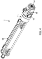
- an oscillating sprinkler 1 mainly comprises a hose connecting module 14, a water inlet module 12, an oscillating range adjusting module 10 (i.e. the one proposed by the present invention), an oscillation driving module 11 and a spraying nozzle module 13, wherein the oscillating range adjusting module 10 of the present invention is connected between the oscillation driving module 11 and the water inlet module 12.
- FIG. 5 shows a first three-dimensional view of an oscillation driving module in combination with the oscillating range adjusting module of the present invention
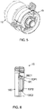
- FIG. 6 shows a cross-sectional view of the oscillating range adjusting module of the present invention
- FIG. 7 shows a first exploded view of the oscillating range adjusting module of the present invention
- FIG. 8 shows a second exploded view of the oscillating range adjusting module of the present invention.
- the oscillating range adjusting module 10 mainly comprises a first adjusting unit 101, a second adjusting unit 102 and an O-ring seal 103. As illustrated in FIG.
- the first adjusting unit 101 comprises a first circular-shaped substrate 1011, a first arc-shaped perforation groove 1015 and a first circular-shaped peripheral wall 1012, wherein the first circular-shaped peripheral wall 1012 is formed on a top surface of the first circular-shaped substrate 1011, and wherein the first arc-shaped perforation groove 1015 is formed on the first circular-shaped substrate 1011.
- a hollow cylinder member 1013 is formed on a center of the first circular-shaped substrate 1011 for use in connection with an inlet tube of a water inlet module 12.
- the first arc-shaped perforation groove 1015 and a third arc-shaped perforation groove 1014 are formed on the first circular-shaped substrate 1011. As shown in FIG. 7 and 8 , the first arc-shaped perforation groove 1015 is located at a position below the hollow cylinder member 1013 and near the first circular-shaped peripheral wall 1012. On the other hand, the third arc-shaped perforation groove 1014 is located above the hollow cylinder member 1013 and near the first circular-shaped peripheral wall 1012. It is worth noting that at least one combination platform 10P1, 10P2 is connected to the peripheral sides of a bottom end of the hollow cylinder member 1013.
- FIG. 7 and 8 show that there is one first combination platform 10P1 and one second combination platform 10P2 connected to the peripheral sides of the bottom end of the hollow cylinder member 1013.
- the first combination platform 10P1 is located between the third arc-shaped perforation groove 1014 and the hollow cylinder member 1013
- the second combination platform 10P2 is located between the first arc-shaped perforation groove 1015 and the hollow cylinder member 1013.
- FIG. 7 and 8 also depict that a first pull member 1016 is connected to an outer surface of the first circular-shaped peripheral wall 1012, and that an arc-shaped groove 1017 is formed on the bottom surface of the first circular-shaped substrate 1011.
- the second adjusting unit 102 comprises a second circular-shaped substrate 1021, a second circular-shaped peripheral wall 1022 and a second arc-shaped perforation groove 1025, wherein a top surface of the second circular-shaped substrate 1021 is connected to a bottom surface of the first circular-shaped substrate 1011.
- the second circular-shaped peripheral wall 1022 is formed on a bottom surface of the second circular-shaped substrate 1021 and the second arc-shaped perforation groove 1025 is formed on the second circular-shaped substrate 1021.
- At least one snapping member 10C1, 10C2 is formed on the top surface of the second circular-shaped substrate 1021 and is configured for snapping the at least one combination platform 10P1, 10P2, when the second circular-shaped substrate 1021 is connected to the first circular-shaped substrate 1011.
- the expression "at least one" means that the number of snapping members may be one or more.
- FIG. 7 and 8 show that one first snapping member 10C1 and one second snapping member 10C2 are formed on the top surface of the second circular-shaped substrate 1021, which respectively snap the first combination platform 10P1 and the second combination platform 10P2, when the second circular-shaped substrate 1021 is connected to the first circular-shaped substrate 1011.
- a combination hole 1023 is formed on a center of the second circular-shaped substrate 1021 and is adopted for connecting between the bottom end of the hollow cylinder member 1013 and a water inlet port of the oscillation driving module 11.
- a second arc-shaped perforation groove 1025 and a fourth arc-shaped perforation groove 1024 are formed on the second circular-shaped substrate 1021.
- the fourth arc-shaped perforation groove 1024 is located at a specific position above the combination hole 1023 and near the second circular-shaped peripheral wall 1022, whereas the second arc-shaped perforation groove 1025 is located at a position below the combination hole 1023 and near the second circular-shaped peripheral wall 1012.
- a second pull member 1026 is connected to an outer surface of the second circular-shaped peripheral wall 1022 and an arc-shaped protrusion 1027 is formed on the top surface of the second circular-shaped substrate 1021, which is configured for sliding in the arc-shaped groove 1017), when the second circular-shaped substrate 1021 is connected to the first circular-shaped substrate 1011.
- the first pull member 1016 consists of a first base portion 11B and a first pull portion 11P
- the second pull member 1026 consists of a second base portion 12B and a second pull portion 12P.
- the O-ring seal 103 is disposed between the bottom end of the hollow cylinder member 1013 and an edge of the combination hole 1023. Moreover, the arc-shaped protrusion 1027 is inserted into the arc-shaped groove 1017 and is capable of sliding in the arc-shaped groove 1017.
- a first insertion member 10S1 and a second insertion member 10S2 are disposed on the top surface of the second circular-shaped substrate 1021, which are adopted for being respectively inserted into the third arc-shaped perforation groove 1014 and the first arc-shaped perforation groove 1015, when the second circular-shaped substrate (1021) is connected to the first circular-shaped substrate (1011).
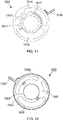
- FIG. 9 shows a front view of a first adjusting unit 101 of the oscillating range adjusting module 10 and FIG. 10 shows a front view of a second adjusting unit 102 of the oscillating range adjusting module 10.
- FIG. 11 shows a rear view of the first adjusting unit 101 and FIG. 12 shows a rear view of the second adjusting unit 102.
- FIG. 13 shows a first front view of the oscillating range adjusting module 10.
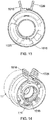
- FIG. 14 shows a three-dimensional view of the oscillation driving module 11 in combination with the oscillating range adjusting module 11, FIG.
- FIG. 15 shows a second front view of the oscillating range adjusting module 10 and FIG. 16 shows another three-dimensional view of the oscillation driving module 11 in combination with the oscillating range adjusting module 10.
- FIG. 13 to 16 are provided for supporting the explanation of how the oscillating range adjusting module 10 of the present invention interacts with the oscillation driving module 11.
- FIG. 9 and 13 to 16 there are not many numeric symbols labeled therein. Simultaneously referring to FIG. 7 to 10 may be helpful for finding related numeric symbols of already described constituting elements of the oscillating range adjusting module 10 of the present invention.
- an oscillating sprinkler 1 integrated with the oscillating range adjusting module 10 of the present invention a user is able to adjust or change an oscillating range of the spraying nozzle module 13 by pulling the first pull member 1016 and/or the second pull member 1026.
- the oscillation driving module 11 of the present invention integrated in the oscillating sprinkler 1 is configured for driving the spraying nozzle module 13 swing back and forth in a user-set oscillating range. From FIG.
- the first swing limiting perforation groove is configured for forming a minimum oscillating range of the spraying nozzle module 13.
- the user is able to set a maximum oscillating range for the spraying nozzle module 13 by pulling the first pull member 1016 and/or the second pull member 1026.
- the intersection between the first arc-shaped perforation groove 1015 on the first circular-shaped substrate 1011 and the second arc-shaped perforation groove 1025 on the second circular-shaped substrate 1021 form a second swing limiting perforation groove, wherein a swing limiting member 111 of the oscillation driving module 11 is limited to swing in the second swing limiting perforation groove.
- the second swing limiting perforation groove is configured for forming a maximum oscillating range of the spraying nozzle module 13.
- the present invention provides the following advantages:
- the present invention provides an oscillating range adjusting module 10 for use in an oscillating sprinkler 1, connected between a water inlet module 12 and an oscillation driving module 11, the oscillating range adjusting module 10 mainly comprising a first adjusting unit 101 and a second adjusting unit 102.
- the water inlet module 12 and the oscillation driving module 11 When assembling the oscillating range adjusting module 10, the water inlet module 12 and the oscillation driving module 11, it is just needed to firstly connect an inlet tube of the water inlet module 12 and an O-ring seal 103 to the first adjusting unit 101, and then to connect a second adjusting unit 102 to the inlet tube and the first adjusting unit 101, such that at least one snapping member 10C1, 10C2 of the second adjusting unit 102 engages with at least one combination platform 10P1, 10P2 of the first adjusting unit 101. Consequently, a modularization assembly of the oscillating range adjusting module 10, the water inlet module 12 and the oscillation driving module 11 is achieved after a water inlet port of the oscillation driving module 11 has been connected to the second adjusting unit 102.
Landscapes
- Nozzles (AREA)
Priority Applications (2)
| Application Number | Priority Date | Filing Date | Title |
|---|---|---|---|
| EP19173676.8A EP3736048B1 (en) | 2019-05-09 | 2019-05-09 | Oscillating range adjusting module for use in oscillating sprinklers |
| PL19173676T PL3736048T3 (pl) | 2019-05-09 | 2019-05-09 | Moduł regulacji zakresu oscylacji do stosowania w zraszaczach oscylacyjnych |
Applications Claiming Priority (1)
| Application Number | Priority Date | Filing Date | Title |
|---|---|---|---|
| EP19173676.8A EP3736048B1 (en) | 2019-05-09 | 2019-05-09 | Oscillating range adjusting module for use in oscillating sprinklers |
Publications (2)
| Publication Number | Publication Date |
|---|---|
| EP3736048A1 EP3736048A1 (en) | 2020-11-11 |
| EP3736048B1 true EP3736048B1 (en) | 2021-09-29 |
Family
ID=66483855
Family Applications (1)
| Application Number | Title | Priority Date | Filing Date |
|---|---|---|---|
| EP19173676.8A Active EP3736048B1 (en) | 2019-05-09 | 2019-05-09 | Oscillating range adjusting module for use in oscillating sprinklers |
Country Status (2)
| Country | Link |
|---|---|
| EP (1) | EP3736048B1 (pl) |
| PL (1) | PL3736048T3 (pl) |
Families Citing this family (1)
| Publication number | Priority date | Publication date | Assignee | Title |
|---|---|---|---|---|
| CN112262745A (zh) * | 2020-11-18 | 2021-01-26 | 宁波威斯麦水暖实业有限公司 | 一种自摇摆双管洒水器 |
Family Cites Families (4)
| Publication number | Priority date | Publication date | Assignee | Title |
|---|---|---|---|---|
| US7255291B1 (en) * | 2006-10-06 | 2007-08-14 | Yuan Mei Corp. | Multifunctional sprinkler structure |
| US7931214B2 (en) * | 2008-09-30 | 2011-04-26 | Robert Bosch Gmbh | Water sprinkler with tube adaptor member |
| CN203990992U (zh) | 2014-07-23 | 2014-12-10 | 宁波美志工具有限公司 | 一种摇摆式喷水装置 |
| CN106824580A (zh) * | 2017-01-23 | 2017-06-13 | 慈溪市博捷金属制品有限公司 | 一种摇摆式洒水器 |
-
2019
- 2019-05-09 EP EP19173676.8A patent/EP3736048B1/en active Active
- 2019-05-09 PL PL19173676T patent/PL3736048T3/pl unknown
Also Published As
| Publication number | Publication date |
|---|---|
| PL3736048T3 (pl) | 2022-01-31 |
| EP3736048A1 (en) | 2020-11-11 |
Similar Documents
| Publication | Publication Date | Title |
|---|---|---|
| US7252246B2 (en) | Oscillating sprinkler with pattern select feature | |
| USD973822S1 (en) | Climbing dome | |
| USD467301S1 (en) | Garden and lawn sprinkler | |
| US7455198B2 (en) | Trigger forward pivot limit for a trigger sprayer | |
| USD481316S1 (en) | Spray dispenser cap | |
| USD668122S1 (en) | Gardening post | |
| US6568610B1 (en) | Flexible lawn and garden spray wand | |
| US11744171B2 (en) | Ready-to-use hose end sprayer | |
| US20060219822A1 (en) | Dual volume shower head system | |
| US6058975A (en) | Connection member of water control valve | |
| US11673154B2 (en) | Oscillating range adjusting module for use in sprinkler | |
| USD574951S1 (en) | Flow tube | |
| HUT68353A (en) | Regulated drip irrigation emitter | |
| WO2015083032A1 (en) | Drip emitter and method for forming a drip irrigation pipe | |
| USD460522S1 (en) | Low pressure fluid flow control valve | |
| EP3736048A1 (en) | Oscillating range adjusting module for use in oscillating sprinklers | |
| USD510402S1 (en) | Gun light | |
| CA3080909C (en) | Showerhead with inline engine porting | |
| CA2919455C (en) | Sprinkler | |
| US20160303583A1 (en) | Sprinkler | |
| US7207604B2 (en) | Snap-fit connection for pool filtration systems | |
| USD535571S1 (en) | Watering timer housing | |
| USD920751S1 (en) | Garden trimmer edger attachment | |
| USD973838S1 (en) | Shroud of an aspirating spray nozzle | |
| USD480783S1 (en) | Orifice mount for high-pressure fluid jet systems |
Legal Events
| Date | Code | Title | Description |
|---|---|---|---|
| PUAI | Public reference made under article 153(3) epc to a published international application that has entered the european phase |
Free format text: ORIGINAL CODE: 0009012 |
|
| STAA | Information on the status of an ep patent application or granted ep patent |
Free format text: STATUS: REQUEST FOR EXAMINATION WAS MADE |
|
| 17P | Request for examination filed |
Effective date: 20200325 |
|
| AK | Designated contracting states |
Kind code of ref document: A1 Designated state(s): AL AT BE BG CH CY CZ DE DK EE ES FI FR GB GR HR HU IE IS IT LI LT LU LV MC MK MT NL NO PL PT RO RS SE SI SK SM TR |
|
| AX | Request for extension of the european patent |
Extension state: BA ME |
|
| GRAP | Despatch of communication of intention to grant a patent |
Free format text: ORIGINAL CODE: EPIDOSNIGR1 |
|
| STAA | Information on the status of an ep patent application or granted ep patent |
Free format text: STATUS: GRANT OF PATENT IS INTENDED |
|
| INTG | Intention to grant announced |
Effective date: 20210413 |
|
| GRAS | Grant fee paid |
Free format text: ORIGINAL CODE: EPIDOSNIGR3 |
|
| GRAA | (expected) grant |
Free format text: ORIGINAL CODE: 0009210 |
|
| STAA | Information on the status of an ep patent application or granted ep patent |
Free format text: STATUS: THE PATENT HAS BEEN GRANTED |
|
| AK | Designated contracting states |
Kind code of ref document: B1 Designated state(s): AL AT BE BG CH CY CZ DE DK EE ES FI FR GB GR HR HU IE IS IT LI LT LU LV MC MK MT NL NO PL PT RO RS SE SI SK SM TR |
|
| REG | Reference to a national code |
Ref country code: GB Ref legal event code: FG4D |
|
| REG | Reference to a national code |
Ref country code: CH Ref legal event code: EP Ref country code: AT Ref legal event code: REF Ref document number: 1433737 Country of ref document: AT Kind code of ref document: T Effective date: 20211015 |
|
| REG | Reference to a national code |
Ref country code: DE Ref legal event code: R096 Ref document number: 602019007925 Country of ref document: DE |
|
| REG | Reference to a national code |
Ref country code: IE Ref legal event code: FG4D |
|
| REG | Reference to a national code |
Ref country code: LT Ref legal event code: MG9D |
|
| PG25 | Lapsed in a contracting state [announced via postgrant information from national office to epo] |
Ref country code: FI Free format text: LAPSE BECAUSE OF FAILURE TO SUBMIT A TRANSLATION OF THE DESCRIPTION OR TO PAY THE FEE WITHIN THE PRESCRIBED TIME-LIMIT Effective date: 20210929 Ref country code: RS Free format text: LAPSE BECAUSE OF FAILURE TO SUBMIT A TRANSLATION OF THE DESCRIPTION OR TO PAY THE FEE WITHIN THE PRESCRIBED TIME-LIMIT Effective date: 20210929 Ref country code: SE Free format text: LAPSE BECAUSE OF FAILURE TO SUBMIT A TRANSLATION OF THE DESCRIPTION OR TO PAY THE FEE WITHIN THE PRESCRIBED TIME-LIMIT Effective date: 20210929 Ref country code: HR Free format text: LAPSE BECAUSE OF FAILURE TO SUBMIT A TRANSLATION OF THE DESCRIPTION OR TO PAY THE FEE WITHIN THE PRESCRIBED TIME-LIMIT Effective date: 20210929 Ref country code: NO Free format text: LAPSE BECAUSE OF FAILURE TO SUBMIT A TRANSLATION OF THE DESCRIPTION OR TO PAY THE FEE WITHIN THE PRESCRIBED TIME-LIMIT Effective date: 20211229 Ref country code: LT Free format text: LAPSE BECAUSE OF FAILURE TO SUBMIT A TRANSLATION OF THE DESCRIPTION OR TO PAY THE FEE WITHIN THE PRESCRIBED TIME-LIMIT Effective date: 20210929 Ref country code: BG Free format text: LAPSE BECAUSE OF FAILURE TO SUBMIT A TRANSLATION OF THE DESCRIPTION OR TO PAY THE FEE WITHIN THE PRESCRIBED TIME-LIMIT Effective date: 20211229 |
|
| REG | Reference to a national code |
Ref country code: NL Ref legal event code: MP Effective date: 20210929 |
|
| REG | Reference to a national code |
Ref country code: AT Ref legal event code: MK05 Ref document number: 1433737 Country of ref document: AT Kind code of ref document: T Effective date: 20210929 |
|
| PG25 | Lapsed in a contracting state [announced via postgrant information from national office to epo] |
Ref country code: LV Free format text: LAPSE BECAUSE OF FAILURE TO SUBMIT A TRANSLATION OF THE DESCRIPTION OR TO PAY THE FEE WITHIN THE PRESCRIBED TIME-LIMIT Effective date: 20210929 Ref country code: GR Free format text: LAPSE BECAUSE OF FAILURE TO SUBMIT A TRANSLATION OF THE DESCRIPTION OR TO PAY THE FEE WITHIN THE PRESCRIBED TIME-LIMIT Effective date: 20211230 |
|
| PG25 | Lapsed in a contracting state [announced via postgrant information from national office to epo] |
Ref country code: AT Free format text: LAPSE BECAUSE OF FAILURE TO SUBMIT A TRANSLATION OF THE DESCRIPTION OR TO PAY THE FEE WITHIN THE PRESCRIBED TIME-LIMIT Effective date: 20210929 |
|
| PG25 | Lapsed in a contracting state [announced via postgrant information from national office to epo] |
Ref country code: IS Free format text: LAPSE BECAUSE OF FAILURE TO SUBMIT A TRANSLATION OF THE DESCRIPTION OR TO PAY THE FEE WITHIN THE PRESCRIBED TIME-LIMIT Effective date: 20220129 Ref country code: SK Free format text: LAPSE BECAUSE OF FAILURE TO SUBMIT A TRANSLATION OF THE DESCRIPTION OR TO PAY THE FEE WITHIN THE PRESCRIBED TIME-LIMIT Effective date: 20210929 Ref country code: RO Free format text: LAPSE BECAUSE OF FAILURE TO SUBMIT A TRANSLATION OF THE DESCRIPTION OR TO PAY THE FEE WITHIN THE PRESCRIBED TIME-LIMIT Effective date: 20210929 Ref country code: PT Free format text: LAPSE BECAUSE OF FAILURE TO SUBMIT A TRANSLATION OF THE DESCRIPTION OR TO PAY THE FEE WITHIN THE PRESCRIBED TIME-LIMIT Effective date: 20220131 Ref country code: NL Free format text: LAPSE BECAUSE OF FAILURE TO SUBMIT A TRANSLATION OF THE DESCRIPTION OR TO PAY THE FEE WITHIN THE PRESCRIBED TIME-LIMIT Effective date: 20210929 Ref country code: ES Free format text: LAPSE BECAUSE OF FAILURE TO SUBMIT A TRANSLATION OF THE DESCRIPTION OR TO PAY THE FEE WITHIN THE PRESCRIBED TIME-LIMIT Effective date: 20210929 Ref country code: EE Free format text: LAPSE BECAUSE OF FAILURE TO SUBMIT A TRANSLATION OF THE DESCRIPTION OR TO PAY THE FEE WITHIN THE PRESCRIBED TIME-LIMIT Effective date: 20210929 Ref country code: CZ Free format text: LAPSE BECAUSE OF FAILURE TO SUBMIT A TRANSLATION OF THE DESCRIPTION OR TO PAY THE FEE WITHIN THE PRESCRIBED TIME-LIMIT Effective date: 20210929 Ref country code: AL Free format text: LAPSE BECAUSE OF FAILURE TO SUBMIT A TRANSLATION OF THE DESCRIPTION OR TO PAY THE FEE WITHIN THE PRESCRIBED TIME-LIMIT Effective date: 20210929 |
|
| REG | Reference to a national code |
Ref country code: DE Ref legal event code: R097 Ref document number: 602019007925 Country of ref document: DE |
|
| PG25 | Lapsed in a contracting state [announced via postgrant information from national office to epo] |
Ref country code: DK Free format text: LAPSE BECAUSE OF FAILURE TO SUBMIT A TRANSLATION OF THE DESCRIPTION OR TO PAY THE FEE WITHIN THE PRESCRIBED TIME-LIMIT Effective date: 20210929 |
|
| PLBE | No opposition filed within time limit |
Free format text: ORIGINAL CODE: 0009261 |
|
| STAA | Information on the status of an ep patent application or granted ep patent |
Free format text: STATUS: NO OPPOSITION FILED WITHIN TIME LIMIT |
|
| 26N | No opposition filed |
Effective date: 20220630 |
|
| PG25 | Lapsed in a contracting state [announced via postgrant information from national office to epo] |
Ref country code: SI Free format text: LAPSE BECAUSE OF FAILURE TO SUBMIT A TRANSLATION OF THE DESCRIPTION OR TO PAY THE FEE WITHIN THE PRESCRIBED TIME-LIMIT Effective date: 20210929 |
|
| REG | Reference to a national code |
Ref country code: CH Ref legal event code: PL |
|
| REG | Reference to a national code |
Ref country code: BE Ref legal event code: MM Effective date: 20220531 |
|
| PG25 | Lapsed in a contracting state [announced via postgrant information from national office to epo] |
Ref country code: MC Free format text: LAPSE BECAUSE OF FAILURE TO SUBMIT A TRANSLATION OF THE DESCRIPTION OR TO PAY THE FEE WITHIN THE PRESCRIBED TIME-LIMIT Effective date: 20210929 Ref country code: LU Free format text: LAPSE BECAUSE OF NON-PAYMENT OF DUE FEES Effective date: 20220509 Ref country code: LI Free format text: LAPSE BECAUSE OF NON-PAYMENT OF DUE FEES Effective date: 20220531 Ref country code: IT Free format text: LAPSE BECAUSE OF FAILURE TO SUBMIT A TRANSLATION OF THE DESCRIPTION OR TO PAY THE FEE WITHIN THE PRESCRIBED TIME-LIMIT Effective date: 20210929 Ref country code: CH Free format text: LAPSE BECAUSE OF NON-PAYMENT OF DUE FEES Effective date: 20220531 |
|
| PG25 | Lapsed in a contracting state [announced via postgrant information from national office to epo] |
Ref country code: IE Free format text: LAPSE BECAUSE OF NON-PAYMENT OF DUE FEES Effective date: 20220509 |
|
| PG25 | Lapsed in a contracting state [announced via postgrant information from national office to epo] |
Ref country code: BE Free format text: LAPSE BECAUSE OF NON-PAYMENT OF DUE FEES Effective date: 20220531 |
|
| PG25 | Lapsed in a contracting state [announced via postgrant information from national office to epo] |
Ref country code: SM Free format text: LAPSE BECAUSE OF FAILURE TO SUBMIT A TRANSLATION OF THE DESCRIPTION OR TO PAY THE FEE WITHIN THE PRESCRIBED TIME-LIMIT Effective date: 20210929 Ref country code: MK Free format text: LAPSE BECAUSE OF FAILURE TO SUBMIT A TRANSLATION OF THE DESCRIPTION OR TO PAY THE FEE WITHIN THE PRESCRIBED TIME-LIMIT Effective date: 20210929 Ref country code: CY Free format text: LAPSE BECAUSE OF FAILURE TO SUBMIT A TRANSLATION OF THE DESCRIPTION OR TO PAY THE FEE WITHIN THE PRESCRIBED TIME-LIMIT Effective date: 20210929 |
|
| PG25 | Lapsed in a contracting state [announced via postgrant information from national office to epo] |
Ref country code: HU Free format text: LAPSE BECAUSE OF FAILURE TO SUBMIT A TRANSLATION OF THE DESCRIPTION OR TO PAY THE FEE WITHIN THE PRESCRIBED TIME-LIMIT; INVALID AB INITIO Effective date: 20190509 |
|
| PG25 | Lapsed in a contracting state [announced via postgrant information from national office to epo] |
Ref country code: TR Free format text: LAPSE BECAUSE OF FAILURE TO SUBMIT A TRANSLATION OF THE DESCRIPTION OR TO PAY THE FEE WITHIN THE PRESCRIBED TIME-LIMIT Effective date: 20210929 |
|
| PG25 | Lapsed in a contracting state [announced via postgrant information from national office to epo] |
Ref country code: MT Free format text: LAPSE BECAUSE OF FAILURE TO SUBMIT A TRANSLATION OF THE DESCRIPTION OR TO PAY THE FEE WITHIN THE PRESCRIBED TIME-LIMIT Effective date: 20210929 |
|
| PGFP | Annual fee paid to national office [announced via postgrant information from national office to epo] |
Ref country code: GB Payment date: 20260324 Year of fee payment: 8 |
|
| PGFP | Annual fee paid to national office [announced via postgrant information from national office to epo] |
Ref country code: PL Payment date: 20260428 Year of fee payment: 8 |
|
| PGFP | Annual fee paid to national office [announced via postgrant information from national office to epo] |
Ref country code: DE Payment date: 20260529 Year of fee payment: 8 |
|
| PGFP | Annual fee paid to national office [announced via postgrant information from national office to epo] |
Ref country code: FR Payment date: 20260522 Year of fee payment: 8 |