EP3735946B1 - Shunt for draining ocular fluid - Google Patents
Shunt for draining ocular fluid Download PDFInfo
- Publication number
- EP3735946B1 EP3735946B1 EP19173178.5A EP19173178A EP3735946B1 EP 3735946 B1 EP3735946 B1 EP 3735946B1 EP 19173178 A EP19173178 A EP 19173178A EP 3735946 B1 EP3735946 B1 EP 3735946B1
- Authority
- EP
- European Patent Office
- Prior art keywords
- tubular body
- conduit
- shunt
- implantation
- ocular fluid
- Prior art date
- Legal status (The legal status is an assumption and is not a legal conclusion. Google has not performed a legal analysis and makes no representation as to the accuracy of the status listed.)
- Active
Links
Images


Classifications
-
- A—HUMAN NECESSITIES
- A61—MEDICAL OR VETERINARY SCIENCE; HYGIENE
- A61F—FILTERS IMPLANTABLE INTO BLOOD VESSELS; PROSTHESES; DEVICES PROVIDING PATENCY TO, OR PREVENTING COLLAPSING OF, TUBULAR STRUCTURES OF THE BODY, e.g. STENTS; ORTHOPAEDIC, NURSING OR CONTRACEPTIVE DEVICES; FOMENTATION; TREATMENT OR PROTECTION OF EYES OR EARS; BANDAGES, DRESSINGS OR ABSORBENT PADS; FIRST-AID KITS
- A61F9/00—Methods or devices for treatment of the eyes; Devices for putting in contact-lenses; Devices to correct squinting; Apparatus to guide the blind; Protective devices for the eyes, carried on the body or in the hand
- A61F9/007—Methods or devices for eye surgery
- A61F9/00781—Apparatus for modifying intraocular pressure, e.g. for glaucoma treatment
-
- C—CHEMISTRY; METALLURGY
- C03—GLASS; MINERAL OR SLAG WOOL
- C03C—CHEMICAL COMPOSITION OF GLASSES, GLAZES OR VITREOUS ENAMELS; SURFACE TREATMENT OF GLASS; SURFACE TREATMENT OF FIBRES OR FILAMENTS MADE FROM GLASS, MINERALS OR SLAGS; JOINING GLASS TO GLASS OR OTHER MATERIALS
- C03C4/00—Compositions for glass with special properties
- C03C4/0007—Compositions for glass with special properties for biologically-compatible glass
-
- A—HUMAN NECESSITIES
- A61—MEDICAL OR VETERINARY SCIENCE; HYGIENE
- A61F—FILTERS IMPLANTABLE INTO BLOOD VESSELS; PROSTHESES; DEVICES PROVIDING PATENCY TO, OR PREVENTING COLLAPSING OF, TUBULAR STRUCTURES OF THE BODY, e.g. STENTS; ORTHOPAEDIC, NURSING OR CONTRACEPTIVE DEVICES; FOMENTATION; TREATMENT OR PROTECTION OF EYES OR EARS; BANDAGES, DRESSINGS OR ABSORBENT PADS; FIRST-AID KITS
- A61F2210/00—Particular material properties of prostheses classified in groups A61F2/00 - A61F2/26 or A61F2/82 or A61F9/00 or A61F11/00 or subgroups thereof
- A61F2210/0004—Particular material properties of prostheses classified in groups A61F2/00 - A61F2/26 or A61F2/82 or A61F9/00 or A61F11/00 or subgroups thereof bioabsorbable
Definitions
- the invention relates to tube shunts and more particularly to a shunt having a tubular body adapted to be attached to sclera for draining ocular fluid from the eye, thereby lowering ocular pressure.
- conventional shunts for draining ocular fluid are made of metal or polymer.
- the shunt may form a scab over a healed cut and the eye of a patient may feel a degree of discomfort due to heavy weight even the shunt is small. Further, there is a concern of risk for metal and polymer staying in the human body after some years, It is always a long term concern of risk, another surgery for removing the shunt is required. It is understood that there is risk in surgery.
- Patent application publication US 2013/0325024 A1 discloses a shunt for draining ocular fluid having the features of claim 1. From patent application publication WO 2016/149425 A1 a shunt for draining ocular fluid is known having the features of claim 2.
- a shunt for draining ocular fluid comprising a tubular body formed of a mesh material including bioactive glass fibers and collagen, the tubular body including an implantation member and a conduit through the implantation member; wherein the implantation member and the conduit are formed integrally.
- the tubular body can be attached to sclera so that ocular fluid may leave the eye to flow through the conduit, thereby lowering ocular pressure.
- the tubular body is formed of a bioactive glass material, i.e., capable of being absorbed by the body tissues. Specifically, the tubular body is attracted to the body tissues and tends to be dissolved by the body tissues. Thus, a glaucoma patient may have a minimum feeling of discomfort when the tubular body is attached to the sclera.
- the tubular body may be absorbed by the body tissues as time goes by, thereby forming a tubular, flexible member for healing purposes.
- the tubular body may be constructed as a double-layer member in which a first layer of the tubular body is formed of the bioactive glass material and a second layer thereof is formed of a bio-glass material.
- the second layer is formed of a bioactive glass material having a high composition of silica or a bio-inert glass material.
- a shunt for draining ocular fluid in accordance with a first preferred embodiment of the invention comprises a tubular body 10 formed of a mesh material including bioactive glass fiber and collagen.
- the tubular body 10 includes an implantation member 12 and a conduit 141 through the implantation member 12.
- the implantation member 12 and the conduit 141 are formed integrally.
- the dispersion capability of the tubular body 10 can be increased or decreased by different compositions of bioactive glass fibers, bioresorable fibers and collagen.
- the tubular body 10 allows ocular fluid in an anterior section of an eye to flow through in a controlled manner for lowering intraocular pressure. As shown, the tubular body 10 does not have a specific direction for implantation into the eye.
- the implantation member 12 can be disposed at either end of the tubular body 10.
- a shunt for draining ocular fluid in accordance with a second preferred embodiment of the invention comprises a tubular body 10 formed of a bioactive glass material.
- the tubular body 10 includes an implantation member 12 and a fluid guide member 14 extending out of the implantation member 12.
- a conduit 141 is disposed through the fluid guide member 14.
- the fluid guide member 14 is perpendicular to the implantation member 12 so that the tubular body 10 is shaped as an L in a longitudinal section.
- the implantation member 12 includes a sharp end 123, a cavity 124 on a lower portion of the sharp end 123, a plurality of sharp projections 122 on both sides of the implantation member 12, and a bottom channel 121 communicating with both the conduit 141 and the cavity 124.
- the conduit 141 has an oval opening at one end. It is noted that the opening may be shaped as a circle, a hexagon, or a polygon in other embodiments.
- the conduit 141 has a smooth surface and has an axial length of less than 0.5mm and a diameter of less than 0.2mm.
- the tubular body 10 of the second preferred embodiment is constructed as a double-layer member in which a first layer 111 of the tubular body 10 is formed of the bioactive glass material and a second layer 112 thereof is formed of a bio-glass material. It may take several months for the second layer 112 to be absorbed or to be degraded in the body tissues if it is formed of a bioactive glass material having a high composition of silica. Alternatively, the second layer 112 is formed of a bio-inert glass material and the second layer 112 is not subject to be absorbed or to be degraded, i.e., remained in the body tissues forever.
- a shunt for draining ocular fluid in accordance with a third preferred embodiment of the invention comprises a tubular body 10 formed of a bioactive glass material.
- the tubular body 10 includes an implantation member 12 and a fluid guide member 14 extending out of the implantation member 12.
- a conduit 141 is disposed through the fluid guide member 14.
- the fluid guide member 14 is aligned with the implantation member 12 so that the tubular body 10 is shaped as an I in a side elevation.
- the implantation member 12 includes a tapered anchor member 122 at one end, a plurality of lengthwise tunnels 1212 equally spaced around and separated from the conduit 141, each tunnel 1212 being parallel to the conduit 141 and passing through the tubular body 10 to have two ends open, an annular groove 13 disposed between the tapered anchor member 122 and the fluid guide member 14, and an annular shoulder 16 disposed between the annular groove 13 and the fluid guide member 14.
- the conduit 141 has a circular opening at one end. It is noted that the opening may be shaped as an oval, a hexagon, or a polygon in other embodiments.
- the tubular body 10 of the third preferred embodiment is constructed as a double-layer member in which an first layer 111 of the tubular body 10 is formed of the bioactive glass material and an second layer 112 thereof is formed of a bio-glass material.
- the second layer 112 may be formed of a bioactive glass material having a high composition of silica or a bio-inert glass material. It may take several years for the second layer 112 to be absorbed or to be degraded in the body tissues if it is formed of a bioactive glass material having a high composition of silica. Alternatively, the second layer 112 is formed of a bio-inert glass material and the second layer 112 is not subject to be absorbed or to be degraded, i.e., remained in the body tissues forever.
- a shunt for draining ocular fluid in accordance with a fourth preferred embodiment of the invention comprises a tubular body 10 including a first layer 111 formed of a bioactive glass material and a second layer 112 formed of a bio-glass material.
- the second layer 112 and the first layer 111 are fused by fusion process.
- the second layer 112 is formed of a bioactive glass material having a high composition of silica or a bio-inert glass material. It may take several months for the second layer 112 to absorb or degrad in the body tissues if it is formed of a bioactive glass material having a high composition of silica.
- the second layer 112 is formed of a bio-inert glass material and the second layer 112 is not subject to degradation, i.e., remained in the body tissues forever.
- a tubular implantation member 12 is comprised of the second layer 112 and the first layer 111 and includes a plurality of substantially half-spherical protrusions 122 on an outer surface for adhering purposes.
- a conduit 141 is integrally formed with and passes through the implantation member 12 to have two ends open.
- a shunt for draining ocular fluid in accordance with a fifth preferred embodiment of the invention comprises a tubular body 10 including an implantation member 12 and a conduit 141 integrally formed with the implantation member 12.
- the implantation member 12 includes a plurality of sharp projections 122 on both sides.
- the conduit 141 is in the implantation member 12 and has one end and two sides open.
- the tubular body 10 is formed of a bioactive glass material.
- the tubular body 10 can be absorbed or degraded in body tissues in several weeks.
- the tubular body 10 can be attached to sclera so that ocular fluid may leave the eye to flow through the conduit 141, thereby lowering ocular pressure.
- the tubular body 10 is formed of a bioactive glass material, i.e., capable of being absorbed by the body tissues. Specifically, the tubular body 10 is attracted to the body tissues and tends to be dissolved by the body tissues. Thus, a glaucoma patient may have a minimum feeling of discomfort when the tubular body 10 is attached to sclera. Also, the tubular body 10 may be absorbed by the body tissues as time goes by, thereby forming a tubular, flexible member for healing purposes. As an end, another surgery to remove the tubular body 10 from the sclera is not required.
- FIGS. 9 to 12 a number of implementations of the tubular body 10 are illustrated.
- the tubular body 10 is mounted at an end of an implantation device 20.
- the implantation device 20 passes through an anterior section 31 of an eye.
- the sharp end 123 of the implantation member 12 facilitates the tubular body 10 to enter and attach to the sclera.
- a medically employee may slightly adjust an angle of the implantation device 20 to attach a maximum portion of the implantation member 12 to the sclera.
- the implantation member 12 of the tubular body 10 is attached to the sclera, and the conduit 141 communicates with the anterior section 31.
- ocular fluid may leave the anterior section 31 through the conduit 141, thereby lowering intraocular pressure.
- the implantation member 12 of the tubular body 10 of the third preferred embodiment is attached to the sclera, and the conduit 141 communicates with the anterior section 31.
- ocular fluid may leave the anterior section 31 through the conduit 141 or the tunnels 1212, thereby lowering intraocular pressure.
Landscapes
- Health & Medical Sciences (AREA)
- Life Sciences & Earth Sciences (AREA)
- Chemical & Material Sciences (AREA)
- Ophthalmology & Optometry (AREA)
- Engineering & Computer Science (AREA)
- General Health & Medical Sciences (AREA)
- Nuclear Medicine, Radiotherapy & Molecular Imaging (AREA)
- Vascular Medicine (AREA)
- Biomedical Technology (AREA)
- Animal Behavior & Ethology (AREA)
- Surgery (AREA)
- Public Health (AREA)
- Veterinary Medicine (AREA)
- Molecular Biology (AREA)
- Heart & Thoracic Surgery (AREA)
- Chemical Kinetics & Catalysis (AREA)
- General Chemical & Material Sciences (AREA)
- Geochemistry & Mineralogy (AREA)
- Materials Engineering (AREA)
- Organic Chemistry (AREA)
- Prostheses (AREA)
- Materials For Medical Uses (AREA)
Description
- The invention relates to tube shunts and more particularly to a shunt having a tubular body adapted to be attached to sclera for draining ocular fluid from the eye, thereby lowering ocular pressure.
- For treating glaucoma, conventional shunts for draining ocular fluid are made of metal or polymer. The shunt may form a scab over a healed cut and the eye of a patient may feel a degree of discomfort due to heavy weight even the shunt is small. Further, there is a concern of risk for metal and polymer staying in the human body after some years, It is always a long term concern of risk, another surgery for removing the shunt is required. It is understood that there is risk in surgery.
- Thus, the need for improvement of the shunt still exists.
Patent application publicationUS 2013/0325024 A1 discloses a shunt for draining ocular fluid having the features of claim 1. From patent application publicationWO 2016/149425 A1 a shunt for draining ocular fluid is known having the features of claim 2. - It is therefore one object of the invention to provide a shunt for draining ocular fluid, comprising a tubular body formed of a mesh material including bioactive glass fibers and collagen, the tubular body including an implantation member and a conduit through the implantation member; wherein the implantation member and the conduit are formed integrally.
- It is another object of the invention to provide a shunt for draining ocular fluid, comprising a tubular body formed of a bioactive glass material, the tubular body including an implantation member and a conduit; wherein the implantation member and the conduit are formed integrally; wherein the implantation member includes at least one anchor member; and wherein the conduit passes through the implantation member.
- The invention has the following advantages and benefits in comparison with the conventional art:
By constructed as above, the tubular body can be attached to sclera so that ocular fluid may leave the eye to flow through the conduit, thereby lowering ocular pressure. Further, the tubular body is formed of a bioactive glass material, i.e., capable of being absorbed by the body tissues. Specifically, the tubular body is attracted to the body tissues and tends to be dissolved by the body tissues. Thus, a glaucoma patient may have a minimum feeling of discomfort when the tubular body is attached to the sclera. Furthermore, the tubular body may be absorbed by the body tissues as time goes by, thereby forming a tubular, flexible member for healing purposes. - The tubular body may be constructed as a double-layer member in which a first layer of the tubular body is formed of the bioactive glass material and a second layer thereof is formed of a bio-glass material. Specifically, the second layer is formed of a bioactive glass material having a high composition of silica or a bio-inert glass material. Thus, it is possible of controlling strength of the tubular body and time for the tubular body to be absorbed by the body tissues by adjusting weight percentages of compositions of the first and second layers.
- The above and other objects, features and advantages of the invention will become apparent from the following detailed description taken with the accompanying drawings.
-
-
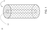
FIG. 1 is a perspective view of a shunt for draining ocular fluid according to a first preferred embodiment of the invention; -
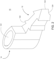
FIG. 2 is a perspective view of a shunt for draining ocular fluid according to a second preferred embodiment of the invention; -
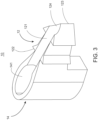
FIG. 3 is another perspective view ofFIG. 2 showing bottom characteristics of the shunt (i.e., the tubular body); -
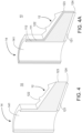
FIG. 4 is a longitudinal sectional view of the shunt shown inFIG. 2 ; -
FIG. 4A is a view similar toFIG. 4 showing a double-layer configuration of the shunt; -
FIG. 5 is a perspective view of a shunt for draining ocular fluid according to a third preferred embodiment of the invention; -
FIG. 6 is a longitudinal sectional view of the shunt shown inFIG. 5 ; -
FIG. 6A is a view similar toFIG. 6 showing a double-layer configuration of the shunt; -
FIG. 7 is a perspective view of a shunt for draining ocular fluid according to a fourth preferred embodiment of the invention; -
FIG. 7A is a longitudinal sectional view of the shunt shown inFIG. 7 ; -
FIG. 8 is a perspective view of a shunt for draining ocular fluid according to a fifth preferred embodiment of the invention; -
FIG. 8A is a side elevation ofFIG. 8 ; -
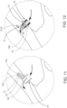
FIG. 9 schematically depicts inserting an implantation device through an anterior section of an eye to attach the tubular body of the first preferred embodiment to sclera; -
FIG. 10 is a view similar toFIG. 9 showing after the implantation device removal, the tubular body being ready to drain ocular fluid; -
FIG. 11 is a detailed view of the area in a circle ofFIG. 10 ; and -
FIG. 12 is a view similar toFIG. 11 showing the tubular body of the third preferred embodiment attached to the sclera and draining ocular fluid. - Referring to
FIG. 1 , a shunt for draining ocular fluid in accordance with a first preferred embodiment of the invention comprises atubular body 10 formed of a mesh material including bioactive glass fiber and collagen. Thetubular body 10 includes animplantation member 12 and aconduit 141 through theimplantation member 12. Theimplantation member 12 and theconduit 141 are formed integrally. The dispersion capability of thetubular body 10 can be increased or decreased by different compositions of bioactive glass fibers, bioresorable fibers and collagen. Thetubular body 10 allows ocular fluid in an anterior section of an eye to flow through in a controlled manner for lowering intraocular pressure. As shown, thetubular body 10 does not have a specific direction for implantation into the eye. Thus, theimplantation member 12 can be disposed at either end of thetubular body 10. - Referring to
FIGS. 2 to 4 , a shunt for draining ocular fluid in accordance with a second preferred embodiment of the invention comprises atubular body 10 formed of a bioactive glass material. Thetubular body 10 includes animplantation member 12 and afluid guide member 14 extending out of theimplantation member 12. Aconduit 141 is disposed through thefluid guide member 14. Thefluid guide member 14 is perpendicular to theimplantation member 12 so that thetubular body 10 is shaped as an L in a longitudinal section. Theimplantation member 12 includes asharp end 123, acavity 124 on a lower portion of thesharp end 123, a plurality ofsharp projections 122 on both sides of theimplantation member 12, and abottom channel 121 communicating with both theconduit 141 and thecavity 124. Theconduit 141 has an oval opening at one end. It is noted that the opening may be shaped as a circle, a hexagon, or a polygon in other embodiments. Theconduit 141 has a smooth surface and has an axial length of less than 0.5mm and a diameter of less than 0.2mm. By constructed as above, thetubular body 10 can be absorbed or be degraded in body tissues in several months to form a tubular, flexible member for healing purposes. - Referring to
FIG. 4A , thetubular body 10 of the second preferred embodiment is constructed as a double-layer member in which afirst layer 111 of thetubular body 10 is formed of the bioactive glass material and asecond layer 112 thereof is formed of a bio-glass material. It may take several months for thesecond layer 112 to be absorbed or to be degraded in the body tissues if it is formed of a bioactive glass material having a high composition of silica. Alternatively, thesecond layer 112 is formed of a bio-inert glass material and thesecond layer 112 is not subject to be absorbed or to be degraded, i.e., remained in the body tissues forever. - Referring to
FIGS. 5 and6 , a shunt for draining ocular fluid in accordance with a third preferred embodiment of the invention comprises atubular body 10 formed of a bioactive glass material. Thetubular body 10 includes animplantation member 12 and afluid guide member 14 extending out of theimplantation member 12. Aconduit 141 is disposed through thefluid guide member 14. Thefluid guide member 14 is aligned with theimplantation member 12 so that thetubular body 10 is shaped as an I in a side elevation. Theimplantation member 12 includes a taperedanchor member 122 at one end, a plurality oflengthwise tunnels 1212 equally spaced around and separated from theconduit 141, eachtunnel 1212 being parallel to theconduit 141 and passing through thetubular body 10 to have two ends open, anannular groove 13 disposed between thetapered anchor member 122 and thefluid guide member 14, and anannular shoulder 16 disposed between theannular groove 13 and thefluid guide member 14. Theconduit 141 has a circular opening at one end. It is noted that the opening may be shaped as an oval, a hexagon, or a polygon in other embodiments. - Referring to
FIG. 6A , thetubular body 10 of the third preferred embodiment is constructed as a double-layer member in which anfirst layer 111 of thetubular body 10 is formed of the bioactive glass material and ansecond layer 112 thereof is formed of a bio-glass material. Thesecond layer 112 may be formed of a bioactive glass material having a high composition of silica or a bio-inert glass material. It may take several years for thesecond layer 112 to be absorbed or to be degraded in the body tissues if it is formed of a bioactive glass material having a high composition of silica. Alternatively, thesecond layer 112 is formed of a bio-inert glass material and thesecond layer 112 is not subject to be absorbed or to be degraded, i.e., remained in the body tissues forever. - Referring to
FIGS. 7 and 7A , a shunt for draining ocular fluid in accordance with a fourth preferred embodiment of the invention comprises atubular body 10 including afirst layer 111 formed of a bioactive glass material and asecond layer 112 formed of a bio-glass material. Thesecond layer 112 and thefirst layer 111 are fused by fusion process. Specifically, thesecond layer 112 is formed of a bioactive glass material having a high composition of silica or a bio-inert glass material. It may take several months for thesecond layer 112 to absorb or degrad in the body tissues if it is formed of a bioactive glass material having a high composition of silica. Alternatively, thesecond layer 112 is formed of a bio-inert glass material and thesecond layer 112 is not subject to degradation, i.e., remained in the body tissues forever. - A
tubular implantation member 12 is comprised of thesecond layer 112 and thefirst layer 111 and includes a plurality of substantially half-spherical protrusions 122 on an outer surface for adhering purposes. Aconduit 141 is integrally formed with and passes through theimplantation member 12 to have two ends open. - Referring to
FIGS. 8 and 8A , a shunt for draining ocular fluid in accordance with a fifth preferred embodiment of the invention comprises atubular body 10 including animplantation member 12 and aconduit 141 integrally formed with theimplantation member 12. Theimplantation member 12 includes a plurality ofsharp projections 122 on both sides. Theconduit 141 is in theimplantation member 12 and has one end and two sides open. Thetubular body 10 is formed of a bioactive glass material. Thus thetubular body 10 can be absorbed or degraded in body tissues in several weeks. By constructed as above, thetubular body 10 can be attached to sclera so that ocular fluid may leave the eye to flow through theconduit 141, thereby lowering ocular pressure. - The
tubular body 10 is formed of a bioactive glass material, i.e., capable of being absorbed by the body tissues. Specifically, thetubular body 10 is attracted to the body tissues and tends to be dissolved by the body tissues. Thus, a glaucoma patient may have a minimum feeling of discomfort when thetubular body 10 is attached to sclera. Also, thetubular body 10 may be absorbed by the body tissues as time goes by, thereby forming a tubular, flexible member for healing purposes. As an end, another surgery to remove thetubular body 10 from the sclera is not required. - Referring to
FIGS. 9 to 12 , a number of implementations of thetubular body 10 are illustrated. - As shown in
FIGS. 9 to 11 in conjunction withFIGS. 2 to 4A , thetubular body 10 is mounted at an end of animplantation device 20. Theimplantation device 20 passes through ananterior section 31 of an eye. Thesharp end 123 of theimplantation member 12 facilitates thetubular body 10 to enter and attach to the sclera. After attaching to the sclera, a medically employee may slightly adjust an angle of theimplantation device 20 to attach a maximum portion of theimplantation member 12 to the sclera. - In the second preferred embodiment, the
implantation member 12 of thetubular body 10 is attached to the sclera, and theconduit 141 communicates with theanterior section 31. Thus, ocular fluid may leave theanterior section 31 through theconduit 141, thereby lowering intraocular pressure. - As shown in
FIG. 12 in conjunction withFIGS. 5 to 6A , theimplantation member 12 of thetubular body 10 of the third preferred embodiment is attached to the sclera, and theconduit 141 communicates with theanterior section 31. Thus, ocular fluid may leave theanterior section 31 through theconduit 141 or thetunnels 1212, thereby lowering intraocular pressure. - While the invention has been described in terms of preferred embodiments, those skilled in the art will recognize that the invention can be practiced with modifications within the scope of the appended claims.
Claims (8)
- A shunt for draining ocular fluid, comprising:a tubular body (10) including an implantation member (12) and a conduit (141) through the implantation member (12);wherein the implantation member (12) and the conduit (141) are formed integrallycharacterised in that
the tubular body (10) is formed of a mesh material including bioactive glass fibers that are capable of being absorbed by body tissue, bioresorable fibers and collagen. - A shunt for draining ocular fluid, comprising:a tubular body (10) including an implantation member (12) and a conduit (141);wherein the implantation member (12) and the conduit (141) are formed integrally;wherein the implantation member (12) includes at least one anchor member (122); andwherein the conduit (141) passes through the implantation member (12)characterised in that
the tubular body (10) is formed of a bioactive glass material that is capable of being absorbed by body tissue. - The shunt for draining ocular fluid of claim 2, wherein the tubular body (10) includes a second layer (112) formed of either a bioactive glass material having a high composition of silica or a bio-inert glass material.
- The shunt for draining ocular fluid of claim 2, wherein the tubular body (10) further comprises a fluid guide member (14) extending out of the implantation member (12); wherein the fluid guide member (14) is perpendicular to the implantation member (12) so that the tubular body (10) is shaped as an L in a longitudinal section; wherein the implantation member (12) includes a sharp end (123), a cavity on a lower portion of the sharp end (123), a plurality of sharp projections (122) on both sides of the implantation member (12), and a bottom channel (121) communicating with both the conduit (141) and the cavity (124).
- The shunt for draining ocular fluid of claim 2, wherein the tubular body (10) further comprises a fluid guide member (14) extending out of the implantation member (12); wherein the fluid guide member (14) is aligned with the implantation member (12) so that the tubular body (10) is shaped as an I in a side elevation; and wherein the implantation member (12) includes a tapered anchor member (122) at one end, a plurality of lengthwise tunnels (1212) equally spaced around and separated from the conduit (141), each tunnel (1212) being parallel to the conduit (141) and passing through the tubular body (10), an annular groove (13) disposed between the tapered anchor member (122) and the fluid guide member (14), and an annular shoulder (16) disposed between the annular groove (13) and the fluid guide member (14).
- The shunt for draining ocular fluid of claim 2, wherein the conduit (141) has two open sides.
- The shunt for draining ocular fluid of claim 2, wherein each of the at least one anchor member (122) is substantially half-spherical or tapered.
- The shunt for draining ocular fluid of claim 2, wherein the conduit (141) has an opening shaped as a circle, an oval, a hexagon, or a polygon.
Priority Applications (1)
| Application Number | Priority Date | Filing Date | Title |
|---|---|---|---|
| EP19173178.5A EP3735946B1 (en) | 2019-05-07 | 2019-05-07 | Shunt for draining ocular fluid |
Applications Claiming Priority (1)
| Application Number | Priority Date | Filing Date | Title |
|---|---|---|---|
| EP19173178.5A EP3735946B1 (en) | 2019-05-07 | 2019-05-07 | Shunt for draining ocular fluid |
Publications (2)
| Publication Number | Publication Date |
|---|---|
| EP3735946A1 EP3735946A1 (en) | 2020-11-11 |
| EP3735946B1 true EP3735946B1 (en) | 2023-05-03 |
Family
ID=66448435
Family Applications (1)
| Application Number | Title | Priority Date | Filing Date |
|---|---|---|---|
| EP19173178.5A Active EP3735946B1 (en) | 2019-05-07 | 2019-05-07 | Shunt for draining ocular fluid |
Country Status (1)
| Country | Link |
|---|---|
| EP (1) | EP3735946B1 (en) |
Family Cites Families (3)
| Publication number | Priority date | Publication date | Assignee | Title |
|---|---|---|---|---|
| US8888734B2 (en) * | 2012-06-05 | 2014-11-18 | Alcon Research, Ltd. | Functionally graded material tube and method for use of the same in implantation |
| BR102013020961A2 (en) * | 2013-08-12 | 2016-03-08 | Univ Fed De São Carlos | vitreous composition, bioactive vitreous fibers and tissues and articles |
| WO2016149425A1 (en) * | 2015-03-16 | 2016-09-22 | Da Silva Curiel Jeannette M A | Method and apparatus for inserting an implant in the cornea of the eye |
-
2019
- 2019-05-07 EP EP19173178.5A patent/EP3735946B1/en active Active
Also Published As
| Publication number | Publication date |
|---|---|
| EP3735946A1 (en) | 2020-11-11 |
Similar Documents
| Publication | Publication Date | Title |
|---|---|---|
| US11491051B2 (en) | Shunt for draining ocular fluid | |
| US20220249286A1 (en) | Ocular implant with stiffness qualities, methods of implantation and system | |
| CA2723019C (en) | Small gauge mechanical tissue cutter/aspirator probe for glaucoma surgery | |
| US20250262090A1 (en) | Glaucoma shunts and related methods of use | |
| US7717872B2 (en) | Fluid shunting apparatus and methods | |
| EP3876819B1 (en) | Endoscopic instrument | |
| US11504275B2 (en) | Methods and apparatus for treating glaucoma | |
| EP2361067B1 (en) | Implant for inserting into the schlemm's canal of an eye | |
| US9044301B1 (en) | Methods, systems and devices for treating glaucoma | |
| US8545430B2 (en) | Expandable ocular devices | |
| EP2677981B1 (en) | Implant for treating glaucoma | |
| EP3730104A1 (en) | Implant device for eye disease for adjusting intraocular pressure | |
| CN101732125B (en) | Flow regulating implants | |
| US20090287143A1 (en) | Small Gauge Mechanical Tissue Cutter/Aspirator Probe For Glaucoma Surgery | |
| US20120310137A1 (en) | Eye shunt with porous structure | |
| WO2017087713A1 (en) | Delivery device systems and implants for treating glaucoma | |
| CA2563364A1 (en) | Indwelling shunt device and methods for treating glaucoma | |
| KR20160016782A (en) | Drain valve implantable in the eye of a patient for the treatment of glaucoma | |
| WO2011089605A2 (en) | Ocular shunt | |
| EP3735946A1 (en) | Shunt for draining ocular fluid | |
| WO2015079999A1 (en) | Lacrimal duct tube | |
| KR20200118291A (en) | Shunt stent for eye drainage | |
| KR102897767B1 (en) | Implant device for eye disease with multiple channels and method for manufacturing the same | |
| JP7220688B2 (en) | Diversion support frame for eyeball drainage | |
| EP3097893A1 (en) | Medical device for treating obstruction of the lacrimal ducts |
Legal Events
| Date | Code | Title | Description |
|---|---|---|---|
| PUAI | Public reference made under article 153(3) epc to a published international application that has entered the european phase |
Free format text: ORIGINAL CODE: 0009012 |
|
| STAA | Information on the status of an ep patent application or granted ep patent |
Free format text: STATUS: THE APPLICATION HAS BEEN PUBLISHED |
|
| AK | Designated contracting states |
Kind code of ref document: A1 Designated state(s): AL AT BE BG CH CY CZ DE DK EE ES FI FR GB GR HR HU IE IS IT LI LT LU LV MC MK MT NL NO PL PT RO RS SE SI SK SM TR |
|
| AX | Request for extension of the european patent |
Extension state: BA ME |
|
| STAA | Information on the status of an ep patent application or granted ep patent |
Free format text: STATUS: REQUEST FOR EXAMINATION WAS MADE |
|
| 17P | Request for examination filed |
Effective date: 20210412 |
|
| RBV | Designated contracting states (corrected) |
Designated state(s): AL AT BE BG CH CY CZ DE DK EE ES FI FR GB GR HR HU IE IS IT LI LT LU LV MC MK MT NL NO PL PT RO RS SE SI SK SM TR |
|
| GRAP | Despatch of communication of intention to grant a patent |
Free format text: ORIGINAL CODE: EPIDOSNIGR1 |
|
| STAA | Information on the status of an ep patent application or granted ep patent |
Free format text: STATUS: GRANT OF PATENT IS INTENDED |
|
| RIC1 | Information provided on ipc code assigned before grant |
Ipc: C03C 4/00 20060101ALI20221019BHEP Ipc: A61F 9/007 20060101AFI20221019BHEP |
|
| INTG | Intention to grant announced |
Effective date: 20221122 |
|
| RIN1 | Information on inventor provided before grant (corrected) |
Inventor name: LU, EMILY Inventor name: LU, MICHELLE Inventor name: TSENG, HSIAO SEN Inventor name: LU, LUKE |
|
| GRAS | Grant fee paid |
Free format text: ORIGINAL CODE: EPIDOSNIGR3 |
|
| GRAA | (expected) grant |
Free format text: ORIGINAL CODE: 0009210 |
|
| STAA | Information on the status of an ep patent application or granted ep patent |
Free format text: STATUS: THE PATENT HAS BEEN GRANTED |
|
| AK | Designated contracting states |
Kind code of ref document: B1 Designated state(s): AL AT BE BG CH CY CZ DE DK EE ES FI FR GB GR HR HU IE IS IT LI LT LU LV MC MK MT NL NO PL PT RO RS SE SI SK SM TR |
|
| REG | Reference to a national code |
Ref country code: GB Ref legal event code: FG4D |
|
| REG | Reference to a national code |
Ref country code: AT Ref legal event code: REF Ref document number: 1563968 Country of ref document: AT Kind code of ref document: T Effective date: 20230515 Ref country code: CH Ref legal event code: EP |
|
| REG | Reference to a national code |
Ref country code: DE Ref legal event code: R096 Ref document number: 602019028257 Country of ref document: DE |
|
| REG | Reference to a national code |
Ref country code: IE Ref legal event code: FG4D |
|
| REG | Reference to a national code |
Ref country code: LT Ref legal event code: MG9D |
|
| REG | Reference to a national code |
Ref country code: NL Ref legal event code: MP Effective date: 20230503 |
|
| REG | Reference to a national code |
Ref country code: AT Ref legal event code: MK05 Ref document number: 1563968 Country of ref document: AT Kind code of ref document: T Effective date: 20230503 |
|
| PG25 | Lapsed in a contracting state [announced via postgrant information from national office to epo] |
Ref country code: SE Free format text: LAPSE BECAUSE OF FAILURE TO SUBMIT A TRANSLATION OF THE DESCRIPTION OR TO PAY THE FEE WITHIN THE PRESCRIBED TIME-LIMIT Effective date: 20230503 Ref country code: PT Free format text: LAPSE BECAUSE OF FAILURE TO SUBMIT A TRANSLATION OF THE DESCRIPTION OR TO PAY THE FEE WITHIN THE PRESCRIBED TIME-LIMIT Effective date: 20230904 Ref country code: NO Free format text: LAPSE BECAUSE OF FAILURE TO SUBMIT A TRANSLATION OF THE DESCRIPTION OR TO PAY THE FEE WITHIN THE PRESCRIBED TIME-LIMIT Effective date: 20230803 Ref country code: NL Free format text: LAPSE BECAUSE OF FAILURE TO SUBMIT A TRANSLATION OF THE DESCRIPTION OR TO PAY THE FEE WITHIN THE PRESCRIBED TIME-LIMIT Effective date: 20230503 Ref country code: ES Free format text: LAPSE BECAUSE OF FAILURE TO SUBMIT A TRANSLATION OF THE DESCRIPTION OR TO PAY THE FEE WITHIN THE PRESCRIBED TIME-LIMIT Effective date: 20230503 Ref country code: AT Free format text: LAPSE BECAUSE OF FAILURE TO SUBMIT A TRANSLATION OF THE DESCRIPTION OR TO PAY THE FEE WITHIN THE PRESCRIBED TIME-LIMIT Effective date: 20230503 |
|
| PG25 | Lapsed in a contracting state [announced via postgrant information from national office to epo] |
Ref country code: RS Free format text: LAPSE BECAUSE OF FAILURE TO SUBMIT A TRANSLATION OF THE DESCRIPTION OR TO PAY THE FEE WITHIN THE PRESCRIBED TIME-LIMIT Effective date: 20230503 Ref country code: PL Free format text: LAPSE BECAUSE OF FAILURE TO SUBMIT A TRANSLATION OF THE DESCRIPTION OR TO PAY THE FEE WITHIN THE PRESCRIBED TIME-LIMIT Effective date: 20230503 Ref country code: LV Free format text: LAPSE BECAUSE OF FAILURE TO SUBMIT A TRANSLATION OF THE DESCRIPTION OR TO PAY THE FEE WITHIN THE PRESCRIBED TIME-LIMIT Effective date: 20230503 Ref country code: LT Free format text: LAPSE BECAUSE OF FAILURE TO SUBMIT A TRANSLATION OF THE DESCRIPTION OR TO PAY THE FEE WITHIN THE PRESCRIBED TIME-LIMIT Effective date: 20230503 Ref country code: IS Free format text: LAPSE BECAUSE OF FAILURE TO SUBMIT A TRANSLATION OF THE DESCRIPTION OR TO PAY THE FEE WITHIN THE PRESCRIBED TIME-LIMIT Effective date: 20230903 Ref country code: HR Free format text: LAPSE BECAUSE OF FAILURE TO SUBMIT A TRANSLATION OF THE DESCRIPTION OR TO PAY THE FEE WITHIN THE PRESCRIBED TIME-LIMIT Effective date: 20230503 Ref country code: GR Free format text: LAPSE BECAUSE OF FAILURE TO SUBMIT A TRANSLATION OF THE DESCRIPTION OR TO PAY THE FEE WITHIN THE PRESCRIBED TIME-LIMIT Effective date: 20230804 |
|
| PG25 | Lapsed in a contracting state [announced via postgrant information from national office to epo] |
Ref country code: FI Free format text: LAPSE BECAUSE OF FAILURE TO SUBMIT A TRANSLATION OF THE DESCRIPTION OR TO PAY THE FEE WITHIN THE PRESCRIBED TIME-LIMIT Effective date: 20230503 |
|
| REG | Reference to a national code |
Ref country code: CH Ref legal event code: PL |
|
| PG25 | Lapsed in a contracting state [announced via postgrant information from national office to epo] |
Ref country code: SK Free format text: LAPSE BECAUSE OF FAILURE TO SUBMIT A TRANSLATION OF THE DESCRIPTION OR TO PAY THE FEE WITHIN THE PRESCRIBED TIME-LIMIT Effective date: 20230503 |
|
| REG | Reference to a national code |
Ref country code: BE Ref legal event code: MM Effective date: 20230531 |
|
| PG25 | Lapsed in a contracting state [announced via postgrant information from national office to epo] |
Ref country code: SM Free format text: LAPSE BECAUSE OF FAILURE TO SUBMIT A TRANSLATION OF THE DESCRIPTION OR TO PAY THE FEE WITHIN THE PRESCRIBED TIME-LIMIT Effective date: 20230503 Ref country code: SK Free format text: LAPSE BECAUSE OF FAILURE TO SUBMIT A TRANSLATION OF THE DESCRIPTION OR TO PAY THE FEE WITHIN THE PRESCRIBED TIME-LIMIT Effective date: 20230503 Ref country code: RO Free format text: LAPSE BECAUSE OF FAILURE TO SUBMIT A TRANSLATION OF THE DESCRIPTION OR TO PAY THE FEE WITHIN THE PRESCRIBED TIME-LIMIT Effective date: 20230503 Ref country code: LU Free format text: LAPSE BECAUSE OF NON-PAYMENT OF DUE FEES Effective date: 20230507 Ref country code: LI Free format text: LAPSE BECAUSE OF NON-PAYMENT OF DUE FEES Effective date: 20230531 Ref country code: EE Free format text: LAPSE BECAUSE OF FAILURE TO SUBMIT A TRANSLATION OF THE DESCRIPTION OR TO PAY THE FEE WITHIN THE PRESCRIBED TIME-LIMIT Effective date: 20230503 Ref country code: DK Free format text: LAPSE BECAUSE OF FAILURE TO SUBMIT A TRANSLATION OF THE DESCRIPTION OR TO PAY THE FEE WITHIN THE PRESCRIBED TIME-LIMIT Effective date: 20230503 Ref country code: CZ Free format text: LAPSE BECAUSE OF FAILURE TO SUBMIT A TRANSLATION OF THE DESCRIPTION OR TO PAY THE FEE WITHIN THE PRESCRIBED TIME-LIMIT Effective date: 20230503 Ref country code: CH Free format text: LAPSE BECAUSE OF NON-PAYMENT OF DUE FEES Effective date: 20230531 |
|
| REG | Reference to a national code |
Ref country code: DE Ref legal event code: R097 Ref document number: 602019028257 Country of ref document: DE |
|
| PG25 | Lapsed in a contracting state [announced via postgrant information from national office to epo] |
Ref country code: MC Free format text: LAPSE BECAUSE OF FAILURE TO SUBMIT A TRANSLATION OF THE DESCRIPTION OR TO PAY THE FEE WITHIN THE PRESCRIBED TIME-LIMIT Effective date: 20230503 |
|
| REG | Reference to a national code |
Ref country code: IE Ref legal event code: MM4A |
|
| PG25 | Lapsed in a contracting state [announced via postgrant information from national office to epo] |
Ref country code: MC Free format text: LAPSE BECAUSE OF FAILURE TO SUBMIT A TRANSLATION OF THE DESCRIPTION OR TO PAY THE FEE WITHIN THE PRESCRIBED TIME-LIMIT Effective date: 20230503 |
|
| PLBE | No opposition filed within time limit |
Free format text: ORIGINAL CODE: 0009261 |
|
| STAA | Information on the status of an ep patent application or granted ep patent |
Free format text: STATUS: NO OPPOSITION FILED WITHIN TIME LIMIT |
|
| 26N | No opposition filed |
Effective date: 20240206 |
|
| PG25 | Lapsed in a contracting state [announced via postgrant information from national office to epo] |
Ref country code: IE Free format text: LAPSE BECAUSE OF NON-PAYMENT OF DUE FEES Effective date: 20230507 |
|
| PG25 | Lapsed in a contracting state [announced via postgrant information from national office to epo] |
Ref country code: IE Free format text: LAPSE BECAUSE OF NON-PAYMENT OF DUE FEES Effective date: 20230507 |
|
| PG25 | Lapsed in a contracting state [announced via postgrant information from national office to epo] |
Ref country code: SI Free format text: LAPSE BECAUSE OF FAILURE TO SUBMIT A TRANSLATION OF THE DESCRIPTION OR TO PAY THE FEE WITHIN THE PRESCRIBED TIME-LIMIT Effective date: 20230503 |
|
| PG25 | Lapsed in a contracting state [announced via postgrant information from national office to epo] |
Ref country code: SI Free format text: LAPSE BECAUSE OF FAILURE TO SUBMIT A TRANSLATION OF THE DESCRIPTION OR TO PAY THE FEE WITHIN THE PRESCRIBED TIME-LIMIT Effective date: 20230503 Ref country code: IT Free format text: LAPSE BECAUSE OF FAILURE TO SUBMIT A TRANSLATION OF THE DESCRIPTION OR TO PAY THE FEE WITHIN THE PRESCRIBED TIME-LIMIT Effective date: 20230503 Ref country code: BE Free format text: LAPSE BECAUSE OF NON-PAYMENT OF DUE FEES Effective date: 20230531 |
|
| PG25 | Lapsed in a contracting state [announced via postgrant information from national office to epo] |
Ref country code: BG Free format text: LAPSE BECAUSE OF FAILURE TO SUBMIT A TRANSLATION OF THE DESCRIPTION OR TO PAY THE FEE WITHIN THE PRESCRIBED TIME-LIMIT Effective date: 20230503 |
|
| PG25 | Lapsed in a contracting state [announced via postgrant information from national office to epo] |
Ref country code: BG Free format text: LAPSE BECAUSE OF FAILURE TO SUBMIT A TRANSLATION OF THE DESCRIPTION OR TO PAY THE FEE WITHIN THE PRESCRIBED TIME-LIMIT Effective date: 20230503 |
|
| PGFP | Annual fee paid to national office [announced via postgrant information from national office to epo] |
Ref country code: DE Payment date: 20250408 Year of fee payment: 7 |
|
| PGFP | Annual fee paid to national office [announced via postgrant information from national office to epo] |
Ref country code: GB Payment date: 20250423 Year of fee payment: 7 |
|
| PGFP | Annual fee paid to national office [announced via postgrant information from national office to epo] |
Ref country code: FR Payment date: 20250408 Year of fee payment: 7 |
|
| PG25 | Lapsed in a contracting state [announced via postgrant information from national office to epo] |
Ref country code: CY Free format text: LAPSE BECAUSE OF FAILURE TO SUBMIT A TRANSLATION OF THE DESCRIPTION OR TO PAY THE FEE WITHIN THE PRESCRIBED TIME-LIMIT; INVALID AB INITIO Effective date: 20190507 |
|
| PG25 | Lapsed in a contracting state [announced via postgrant information from national office to epo] |
Ref country code: HU Free format text: LAPSE BECAUSE OF FAILURE TO SUBMIT A TRANSLATION OF THE DESCRIPTION OR TO PAY THE FEE WITHIN THE PRESCRIBED TIME-LIMIT; INVALID AB INITIO Effective date: 20190507 |
|
| PG25 | Lapsed in a contracting state [announced via postgrant information from national office to epo] |
Ref country code: TR Free format text: LAPSE BECAUSE OF FAILURE TO SUBMIT A TRANSLATION OF THE DESCRIPTION OR TO PAY THE FEE WITHIN THE PRESCRIBED TIME-LIMIT Effective date: 20230503 |