EP3735927A1 - Methods and devices for actuating surgical instruments - Google Patents
Methods and devices for actuating surgical instruments Download PDFInfo
- Publication number
- EP3735927A1 EP3735927A1 EP20181736.8A EP20181736A EP3735927A1 EP 3735927 A1 EP3735927 A1 EP 3735927A1 EP 20181736 A EP20181736 A EP 20181736A EP 3735927 A1 EP3735927 A1 EP 3735927A1
- Authority
- EP
- European Patent Office
- Prior art keywords
- elongate
- elongate member
- end effector
- actuation
- proximal
- Prior art date
- Legal status (The legal status is an assumption and is not a legal conclusion. Google has not performed a legal analysis and makes no representation as to the accuracy of the status listed.)
- Granted
Links
Images















Classifications
-
- A—HUMAN NECESSITIES
- A61—MEDICAL OR VETERINARY SCIENCE; HYGIENE
- A61B—DIAGNOSIS; SURGERY; IDENTIFICATION
- A61B18/00—Surgical instruments, devices or methods for transferring non-mechanical forms of energy to or from the body
- A61B18/04—Surgical instruments, devices or methods for transferring non-mechanical forms of energy to or from the body by heating
- A61B18/12—Surgical instruments, devices or methods for transferring non-mechanical forms of energy to or from the body by heating by passing a current through the tissue to be heated, e.g. high-frequency current
- A61B18/14—Probes or electrodes therefor
- A61B18/1442—Probes having pivoting end effectors, e.g. forceps
- A61B18/1445—Probes having pivoting end effectors, e.g. forceps at the distal end of a shaft, e.g. forceps or scissors at the end of a rigid rod
-
- A—HUMAN NECESSITIES
- A61—MEDICAL OR VETERINARY SCIENCE; HYGIENE
- A61B—DIAGNOSIS; SURGERY; IDENTIFICATION
- A61B17/00—Surgical instruments, devices or methods
- A61B17/28—Surgical forceps
- A61B17/29—Forceps for use in minimally invasive surgery
- A61B17/295—Forceps for use in minimally invasive surgery combined with cutting implements
-
- A—HUMAN NECESSITIES
- A61—MEDICAL OR VETERINARY SCIENCE; HYGIENE
- A61B—DIAGNOSIS; SURGERY; IDENTIFICATION
- A61B17/00—Surgical instruments, devices or methods
- A61B17/28—Surgical forceps
- A61B17/29—Forceps for use in minimally invasive surgery
-
- A—HUMAN NECESSITIES
- A61—MEDICAL OR VETERINARY SCIENCE; HYGIENE
- A61B—DIAGNOSIS; SURGERY; IDENTIFICATION
- A61B17/00—Surgical instruments, devices or methods
- A61B2017/00526—Methods of manufacturing
-
- A—HUMAN NECESSITIES
- A61—MEDICAL OR VETERINARY SCIENCE; HYGIENE
- A61B—DIAGNOSIS; SURGERY; IDENTIFICATION
- A61B17/00—Surgical instruments, devices or methods
- A61B17/28—Surgical forceps
- A61B17/29—Forceps for use in minimally invasive surgery
- A61B2017/2901—Details of shaft
- A61B2017/2902—Details of shaft characterized by features of the actuating rod
- A61B2017/2903—Details of shaft characterized by features of the actuating rod transferring rotary motion
-
- A—HUMAN NECESSITIES
- A61—MEDICAL OR VETERINARY SCIENCE; HYGIENE
- A61B—DIAGNOSIS; SURGERY; IDENTIFICATION
- A61B17/00—Surgical instruments, devices or methods
- A61B17/28—Surgical forceps
- A61B17/29—Forceps for use in minimally invasive surgery
- A61B2017/2901—Details of shaft
- A61B2017/2905—Details of shaft flexible
-
- A—HUMAN NECESSITIES
- A61—MEDICAL OR VETERINARY SCIENCE; HYGIENE
- A61B—DIAGNOSIS; SURGERY; IDENTIFICATION
- A61B17/00—Surgical instruments, devices or methods
- A61B17/28—Surgical forceps
- A61B17/29—Forceps for use in minimally invasive surgery
- A61B17/2909—Handles
- A61B2017/291—Handles the position of the handle being adjustable with respect to the shaft
-
- A—HUMAN NECESSITIES
- A61—MEDICAL OR VETERINARY SCIENCE; HYGIENE
- A61B—DIAGNOSIS; SURGERY; IDENTIFICATION
- A61B17/00—Surgical instruments, devices or methods
- A61B17/28—Surgical forceps
- A61B17/29—Forceps for use in minimally invasive surgery
- A61B17/2909—Handles
- A61B2017/2912—Handles transmission of forces to actuating rod or piston
-
- A—HUMAN NECESSITIES
- A61—MEDICAL OR VETERINARY SCIENCE; HYGIENE
- A61B—DIAGNOSIS; SURGERY; IDENTIFICATION
- A61B17/00—Surgical instruments, devices or methods
- A61B17/28—Surgical forceps
- A61B17/29—Forceps for use in minimally invasive surgery
- A61B2017/2926—Details of heads or jaws
- A61B2017/2927—Details of heads or jaws the angular position of the head being adjustable with respect to the shaft
-
- A—HUMAN NECESSITIES
- A61—MEDICAL OR VETERINARY SCIENCE; HYGIENE
- A61B—DIAGNOSIS; SURGERY; IDENTIFICATION
- A61B17/00—Surgical instruments, devices or methods
- A61B17/28—Surgical forceps
- A61B17/29—Forceps for use in minimally invasive surgery
- A61B2017/2926—Details of heads or jaws
- A61B2017/2927—Details of heads or jaws the angular position of the head being adjustable with respect to the shaft
- A61B2017/2929—Details of heads or jaws the angular position of the head being adjustable with respect to the shaft with a head rotatable about the longitudinal axis of the shaft
-
- A—HUMAN NECESSITIES
- A61—MEDICAL OR VETERINARY SCIENCE; HYGIENE
- A61B—DIAGNOSIS; SURGERY; IDENTIFICATION
- A61B17/00—Surgical instruments, devices or methods
- A61B17/28—Surgical forceps
- A61B17/29—Forceps for use in minimally invasive surgery
- A61B2017/2926—Details of heads or jaws
- A61B2017/2932—Transmission of forces to jaw members
-
- A—HUMAN NECESSITIES
- A61—MEDICAL OR VETERINARY SCIENCE; HYGIENE
- A61B—DIAGNOSIS; SURGERY; IDENTIFICATION
- A61B17/00—Surgical instruments, devices or methods
- A61B17/28—Surgical forceps
- A61B17/29—Forceps for use in minimally invasive surgery
- A61B2017/2926—Details of heads or jaws
- A61B2017/2932—Transmission of forces to jaw members
- A61B2017/2939—Details of linkages or pivot points
- A61B2017/294—Connection of actuating rod to jaw, e.g. releasable
-
- A—HUMAN NECESSITIES
- A61—MEDICAL OR VETERINARY SCIENCE; HYGIENE
- A61B—DIAGNOSIS; SURGERY; IDENTIFICATION
- A61B18/00—Surgical instruments, devices or methods for transferring non-mechanical forms of energy to or from the body
- A61B2018/00571—Surgical instruments, devices or methods for transferring non-mechanical forms of energy to or from the body for achieving a particular surgical effect
- A61B2018/00601—Cutting
-
- A—HUMAN NECESSITIES
- A61—MEDICAL OR VETERINARY SCIENCE; HYGIENE
- A61B—DIAGNOSIS; SURGERY; IDENTIFICATION
- A61B18/00—Surgical instruments, devices or methods for transferring non-mechanical forms of energy to or from the body
- A61B2018/00571—Surgical instruments, devices or methods for transferring non-mechanical forms of energy to or from the body for achieving a particular surgical effect
- A61B2018/0063—Sealing
-
- A—HUMAN NECESSITIES
- A61—MEDICAL OR VETERINARY SCIENCE; HYGIENE
- A61B—DIAGNOSIS; SURGERY; IDENTIFICATION
- A61B18/00—Surgical instruments, devices or methods for transferring non-mechanical forms of energy to or from the body
- A61B18/04—Surgical instruments, devices or methods for transferring non-mechanical forms of energy to or from the body by heating
- A61B18/12—Surgical instruments, devices or methods for transferring non-mechanical forms of energy to or from the body by heating by passing a current through the tissue to be heated, e.g. high-frequency current
- A61B18/14—Probes or electrodes therefor
- A61B18/1442—Probes having pivoting end effectors, e.g. forceps
- A61B2018/1452—Probes having pivoting end effectors, e.g. forceps including means for cutting
- A61B2018/1455—Probes having pivoting end effectors, e.g. forceps including means for cutting having a moving blade for cutting tissue grasped by the jaws
-
- Y—GENERAL TAGGING OF NEW TECHNOLOGICAL DEVELOPMENTS; GENERAL TAGGING OF CROSS-SECTIONAL TECHNOLOGIES SPANNING OVER SEVERAL SECTIONS OF THE IPC; TECHNICAL SUBJECTS COVERED BY FORMER USPC CROSS-REFERENCE ART COLLECTIONS [XRACs] AND DIGESTS
- Y10—TECHNICAL SUBJECTS COVERED BY FORMER USPC
- Y10T—TECHNICAL SUBJECTS COVERED BY FORMER US CLASSIFICATION
- Y10T29/00—Metal working
- Y10T29/49—Method of mechanical manufacture
- Y10T29/49826—Assembling or joining
- Y10T29/49863—Assembling or joining with prestressing of part
Definitions
- the present disclosure relates generally to methods and devices for actuating surgical instruments.
- Minimally invasive surgical techniques such as endoscopies and laparoscopies are often preferred over traditional surgeries because the recovery time, pain, and surgery-related complications are typically less with minimally invasive surgical techniques.
- surgeons Rather than cut open large portions of the body in order to access inner cavities, surgeons either rely on natural orifices of the body or create one or more small orifices in which surgical instruments can be inserted to allow surgeons to visualize and operate at the surgical site.
- Some minimally invasive procedures can require that a working end of a device, which is inserted into the body, be articulated to angularly reorient the working end relative to the tissue.
- a working end of a device which is inserted into the body, be articulated to angularly reorient the working end relative to the tissue.
- Such angulation is often achieved via one or more cables attached to the jaws.
- the cables are subject to high tensions which makes opening and closing of the jaws with precision difficult.
- a surgical device in one embodiment includes a handle, a shaft assembly, and an end effector.
- the handle can have an actuation mechanism coupled thereto.
- the shaft assembly can extend distally from the handle, can include an outer elongate shell defining an inner lumen, and can include first and second elongate members extending longitudinally within the inner lumen.
- the end effector can be coupled to a distal end of the shaft assembly.
- the actuation mechanism can be configured to be actuated by a user so as to simultaneously cause a first force to be applied to one of the first and second elongate members, and thereby cause the one of the first and second elongate members to slidably translate proximally and longitudinally within the inner lumen, and cause a second force to be applied to the other of the first and second elongate members, and thereby cause the other of the first and second elongate members to slidably translate distally and longitudinally within the inner lumen.
- the translation of the first and second elongate members can cause articulation of the end effector.
- the shaft assembly can include first and second elongate tubes.
- the first elongate member can be positioned within the first elongate tube in a fixed position relative thereto.
- the second elongate member can be positioned within the second elongate tube in a fixed position relative thereto.
- the actuation mechanism can be configured to move the first and second elongate tubes in response to the actuation of the actuation mechanism, thereby causing the translation of the first and second elongate members.
- the first elongate member can be attached to the first elongate tube via one of welding and crimping
- the second elongate member can be attached to the second elongate tube via one of welding and crimping.
- first and second elongate tubes in a default state of the surgical device can be tensioned in a distal direction and the first and second elongate members in the default state can be tensioned in a proximal direction
- the surgical device can include first and second stabilizing members.
- the first stabilizing member can be attached to the first elongate tube
- the second stabilizing member can be attached to the second elongate tube
- the actuation of the actuation mechanism can be configured to simultaneously longitudinally translate the first stabilizing member, thereby causing the longitudinal translation of the first elongate member, and longitudinally translate the second stabilizing member, thereby causing the longitudinal translation of the second elongate member.
- the surgical device can include a second actuation mechanism configured to be actuated by the user so as to rotate the first and second stabilizing members about a longitudinal axis of the outer elongate shell so as to cause rotation of the end effector about the longitudinal axis.
- the surgical device can include first and second stabilizing members.
- the first stabilizing member can be attached to the first elongate member via one of welding, crimping, and interference fit.
- the second stabilizing member can be attached to the second elongate member via one of welding, crimping, and interference fit.
- the actuation of the actuation mechanism can be configured to simultaneously longitudinally translate the first stabilizing member, thereby causing the longitudinal translation of the first elongate member, and longitudinally translate the second stabilizing member, thereby causing the longitudinal translation of the second elongate member.
- first and second elongate members in a resting state can be tensioned at a non-zero load.
- the actuation mechanism includes one of a rotatable knob, a slidable lever, and a movable handle.
- a method of assembling the surgical device in one embodiment includes advancing the first elongate member into a first passageway of a first tube of the shaft assembly, coupling the first elongate member to the end effector, and with the first elongate member coupled to the end effector and within the first passageway, tensioning the first elongate member in a distal direction and tensioning the first tube in a proximal direction so that the first tube pushes proximally against the actuation mechanism and so that the first elongate member and the first tube are simultaneously tensioned.
- the method can have any number of variations.
- the first and second elongate members and the first and second tubes can be tensioned from distal ends thereof.
- the method can include, prior to the simultaneous tensioning of the first elongate member and the first tube, attaching a proximal end of a first flexible elongate band to a distal end of the first elongate member.
- the method can include, prior to the simultaneous tensioning of the second elongate member and the second tube, attaching a proximal end of a second flexible elongate band to a distal end of the second elongate member.
- the method can include attaching a distal end of the first flexible elongate band to the end effector, and attaching a distal end of the second flexible elongate band to the end effector.
- the surgical device can have any number of variations.
- the surgical device can include a handle.
- the handle can have the actuation mechanism coupled thereto.
- the shaft assembly can extend distally from the handle.
- a method of assembling a surgical device in one embodiment includes slidably adjusting a position of a first elongate member within a first inner lumen extending through a first tubular member, slidably adjusting a position of a second elongate member within a second inner lumen extending through a second tubular member, coupling an end effector to the first and second elongate members, and coupling an actuation mechanism to the first and second tubular members.
- the end effector can be configured to manipulate tissue.
- the actuation mechanism coupled to the first and second tubular members can be configured to be selectively actuated so as to cause the first elongate member and the first tube to move as a unit in one of the proximal and distal directions and to cause the second elongate member and the second tube to move as a unit in the other of the proximal and distal directions, thereby causing articulation of the end effector.
- securing the first elongate member and the first tubular member in the fixed position relative to one another can include one of crimping the first elongate member and the first tubular member together and welding the first elongate member and the first tubular member together.
- the method can include securing a distal end of a first rigid rod to a proximal end of a first flexible band to form the first elongate member, securing a distal end of the first flexible band to the end effector, securing a distal end of a second rigid rod to a proximal end of a second flexible band to form the second elongate member, and securing a distal end of the second flexible band to the end effector.
- the first band can be configured to move with the first elongate member and the first tube as a unit in the one of the proximal and distal directions
- the second band can be configured to move with the second elongate member and the second tube as a unit in the other of the proximal and distal directions.
- like-named components of the embodiments generally have similar features, and thus within a particular embodiment each feature of each like-named component is not necessarily fully elaborated upon.
- linear or circular dimensions are used in the description of the disclosed systems, devices, and methods, such dimensions are not intended to limit the types of shapes that can be used in conjunction with such systems, devices, and methods.
- a person skilled in the art will recognize that an equivalent to such linear and circular dimensions can easily be determined for any geometric shape. Sizes and shapes of the systems and devices, and the components thereof, can depend at least on the anatomy of the subject in which the systems and devices will be used, the size and shape of components with which the systems and devices will be used, and the methods and procedures in which the systems and devices will be used.
- a surgical device can include one or more actuation shafts configured to facilitate actuation of the device, e.g., articulation of an end effector of the device, opening and closing of jaws at a distal end of the device, moving a cutting element of the device, etc.
- the device can include four actuation shafts, two actuation shafts to facilitate articulation of the device, one actuation shaft to facilitate opening and closing of jaws at a distal end of the device, and one actuation shaft to facilitate moving a cutting element of the device.
- each of the one or more actuation shafts can include a distal elongate member and a proximal elongate member having a distal end attached to a proximal end of the distal elongate member.
- the proximal elongate member can be rigid, which can help ease insertion of the device into a patient's body directly or through an access device such as a trocar, can facilitate smooth, stable longitudinal translation of the actuation shaft to actuate the device, and/or can facilitate making actuation shafts in a variety of longitudinal lengths since the proximal elongate member can simply be cut to have a desired longitudinal length.
- each of the one or more actuation shafts can include a tubular member configured to seat the proximal elongate member therein.
- the tubular member can facilitate attachment of the actuation shaft to an actuator configured to be manually manipulated by a user to cause the desired actuation, e.g., articulation, jaw opening/closing, cutting element movement, etc., and/or can facilitate tensioning of the actuation shaft.
- the device sagging or being loose can make the device more difficult to advance into a patient because sagging and looseness adversely affects stability, can make the device more difficult to desirably position relative to a surgical target because sagging and looseness adversely affects stability, can inhibit the use of the device in surgical tasks such as otomy creation and tissue manipulation and grasping, and/or can make the device more difficult to actuate since increased force applied by a user can be necessary to overcome the sagging or looseness of the device.
- a surgical device including at least one actuation shaft having a rigid proximal portion and a flexible distal portion (e.g., including a rigid proximal elongate member attached to a flexible distal elongate member) can be manufactured to reduce looseness or tolerance.
- the reduction can, in an exemplary embodiment, reduce the looseness or tolerance to substantially zero.
- looseness or tolerance may not be precisely zero but nevertheless be considered to be substantially zero due to, e.g., tolerances in measurement devices.
- the surgical device can thus be manufactured to neutralize tolerance arising from presence of the flexible distal portion.
- the tolerance can be neutralized by simultaneously applying a distally-directed force to a tubular member of the actuation shaft so as to push the tubular member distally and applying a proximally-directed force to a rigid proximal elongate member of the actuation shaft, and accordingly to a flexible distal elongate member of the actuation shaft attached thereto, so as to pull the flexible distal elongate member and the rigid proximal elongate member proximally, thereby reducing sagging and looseness.
- the tensioned tube and the tensioned rigid proximal elongate member can then be attached together to maintain the load and achieve the reduced sagging and looseness in the assembled device.
- the proximally-directed force can be applied to the rigid proximal elongate member (and flexible distal elongate member attached thereto) after a distal end of the flexible distal elongate member has been attached to an end effector of the surgical device, which can facilitate the tensioning by holding the distal end of the flexible distal elongate member in a substantially fixed position during the tensioning.
- the distally-directed force can be applied to the tubular member after assembly of an actuator of the surgical device associated with the actuation shaft being tensioned, which can facilitate the tensioning by allowing a distal end of the tubular member to push against the actuator during the tensioning.
- FIG. 1 illustrates one embodiment of a surgical device 2 that can include a proximal handle portion 4 having a shaft assembly 6 extending distally therefrom.
- the device 2 can include a working element 8, also referred to herein as an "end effector," coupled to a distal end of the shaft assembly 6.
- the end effector 8 can be coupled to the shaft assembly 6 at a pivot joint 10.
- a proximal end of the end effector 8 can be pivotally coupled to the joint 10 at the distal end of the shaft assembly 6.
- the end effector 8 can have a variety of sizes, shapes, and configurations. As shown in FIGS. 1-3 , the end effector 8, including the first and second jaws 12a, 12b, can be disposed at a distal end of the surgical device 2.
- the end effector 8 in this illustrated embodiment includes a tissue grasper having a pair of opposed jaws 12a, 12b configured to move between open and closed positions.
- the end effector 8 can have other configurations, e.g., scissors, a babcock, a retractor, etc.
- the end effector 8 can be rigid.
- the end effector 8 can include the first, top, or upper jaw 12a and the second, bottom, or lower jaw 12b pivotally connected together at the pivot joint 10.
- first jaw 12a and the second jaw 12b can include spacers 30 on facing tissue engagement surfaces thereof.
- the spacers 30 can be configured to maintain a minimum gap of space between the jaws 12a, 12b, e.g., between the tissue engagement surfaces thereof, when the jaws 12a, 12b are in the closed position.
- the gap of space can help prevent electrodes 24, discussed further below, from becoming damaged and/or from creating a closed circuit loop between the jaws 12a, 12b, as opposed to a closed circuit loop with tissue engaged between the jaws 12a, 12b.
- only the top jaw includes spacers 30 extending therefrom toward the bottom jaw 12b, as shown in FIG. 3 .
- only the bottom jaw may include spacers, or both the top and bottom jaws may include spacers.
- One or both of the jaws 12a, 12b can include the electrodes 24, which can be configured to contact tissue positioned between the jaws 12a, 12b and to apply energy thereto.
- the electrodes 24 are arranged longitudinally along the bottom jaw 12b in this illustrated embodiment, but the electrodes 24 can be arranged in any of a variety of ways on the upper jaw 12a and/or the lower jaw 12b.
- the handle portion 4 can have a variety of sizes, shapes, and configurations.
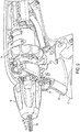
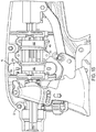
- the handle portion 4 can include a main housing 32, which can house a variety of elements therein and can have some elements accessible outside thereof, such as a first actuator 13, a second actuator 14, a third actuator 16, a fourth actuator 18, and a fifth actuator 20.
- the first actuator 13 can be configured to effect the opening and closing of the opposed jaws 12a, 12b, e.g., movement of the jaws 12a, 12b toward and away from one another.
- the jaws 12a, 12b in FIGS. 1-3 and 6 are shown in the open position.
- the upper jaw 12a can be configured to move relative to the bottom jaw 12b, which can remain stationary relative to the shaft assembly 6, to effect the opening and closing of the end effector 8.
- the bottom jaw in order to effect opening and closing of the end effector, can be configured to move relative to the upper jaw, or both the upper and lower jaws can be configured to move relative to the shaft assembly.
- the second actuator 14 can be configured to effect articulation of the end effector 8, e.g., movement of both jaws 12a, 12b in a same direction relative to a longitudinal axis A of the shaft assembly 6.
- the articulation can be independent of the opening and closing of the jaws 12a, 12b.
- the end effector 8 in FIGS. 1-3 is shown in an unarticulated position, e.g., at a zero angle relative to the longitudinal axis A.
- the second actuator 14 can be operatively connected to an actuation mechanism, which can be disposed within the main housing 32 and is discussed further below, such that actuation of the second actuator 14, e.g., manual movement thereof by a user, can cause articulation of the end effector 8.
- the second actuator 14 can be configured to be actuated so as to cause the jaws 12a, 12b to articulate in opposite directions D1, D2 (shown in FIG. 3 ) relative to the longitudinal axis A.
- the second actuator 14 can have a variety of sizes, shapes, and configurations.
- the second actuator 14 can include a rotatable knob. Rotation of the second actuator 14 in one direction (e.g., clockwise) can be configured to cause articulation of the end effector 8 in the first direction D1 (e.g., right) and rotation of the second actuator 14 in the opposite direction (e.g., counterclockwise) can be configured to cause articulation of the end effector 8 in the second direction D2 (e.g., left).
- the knob 14 can be rigid.
- the knob 16 can include a moveable ring, as shown in FIG. 5 .
- the knob 14 can include one or more finger depressions on an exterior surface thereof, as in this illustrated embodiment. The finger depressions can facilitate manual movement of the knob 14 using one or more fingers seated in the finger depressions. As in this illustrated embodiment, the finger depressions can extend around an entire circumference of the knob's exterior surface.
- the third actuator 16 can be configured to rotate the shaft assembly 6 and the end effector 8 about the longitudinal axis A of the shaft assembly 6.
- the third actuator 16 includes a rotatable knob in this illustrated embodiment that can be rotated about the longitudinal axis A, but the third actuator 16 can have a variety of other configurations, e.g., a lever, a button, a movable handle, etc.
- the third actuator 16 can be configured to continuously and repeatedly rotate the shaft assembly 6 and the end effector 8 360° in both clockwise and counterclockwise directions.
- the shaft assembly 6 can be configured for unlimited bi-directional rotation.
- the shaft assembly 6 and the end effector 8 can be rotated less than 360° as desired during performance of a surgical procedure (e.g., rotated 20°, rotated 90°, rotated 150°, etc.) and can be rotated more than 360° as desired during performance of a surgical procedure (e.g., rotated 450°, rotated 480°, rotated 720°, etc.).
- the fourth actuator 18 can be configured to translate a cutting element 26 (e.g., a knife, a blade, etc.) along the end effector 8.
- the cutting element 26 can be configured to cut tissue positioned between the jaws 12a, 12b, as will be appreciated by a person skilled in the art.
- the jaws 12a, 12b can include an elongate slot 28 therein (the slot in the upper jaw 12a is obscured in FIGS. 3 and 6 ) through which the cutting element 2 can be configured to slide.
- the surgical device 2 can be powered and be configured as an electrosurgical tool configured to apply energy to tissue, such as radiofrequency (RF) energy.
- the handle portion 4 can have a power cord 22 extending proximally therefrom that can be configured to supply electrical power to the device 2, such as by connecting to a generator, by plugging into an electrical outlet, etc.
- the fifth actuator 20 can be configured to turn on and off the application of the energy, which can be delivered to tissue via the electrodes 24.
- the fifth actuator 20 includes a button in this illustrated embodiment, but the fifth actuator 20 can have other configurations, e.g., a knob, a lever, a movable handle, a switch, etc.
- the surgical device can be unpowered, e.g., not be configured to apply energy to tissue.
- the shaft assembly 6 can have a variety of sizes, shapes, and configurations.
- the shaft assembly 6 can have any longitudinal length, although in an exemplary embodiment it can be long enough to allow the handle portion 4 to be manipulated outside a patient's body while the shaft assembly 6 extends through an opening in the body with the end effector 8 disposed within a body cavity, e.g., have a longitudinal length of about 33 cm. In this way, the end effector 8 can be easily manipulated when the device 2 is in use during a surgical procedure.
- the shaft assembly 6 can have any diameter.
- the shaft assembly 6 can include an outer elongate shaft 34 (also referred to herein an "outer shell") and at least one actuation shaft extending between the handle portion 4 and the end effector 8.
- the one or more actuation shafts can be configured to facilitate articulation of the end effector 8, to facilitate opening/closing of the end effector 8, and/or to facilitate movement of the cutting element 26 along the end effector 8.
- the device 2 can include first and second actuation shafts configured to facilitate articulation of the end effector 8, a third actuation shaft configured to facilitate opening/closing of the end effector 8, and a fourth actuation shaft configured to facilitate movement of the cutting element 26 along the end effector 8.
- the outer shell 34 can have a diameter in a range of about 0.2 in. to 0.221 in.
- a person skilled in the art will appreciate that an element may not have a diameter of a precisely value but nevertheless be considered to have a diameter of about that value due to, e.g., manufacturing tolerances.
- each of the actuation shafts can include a distal elongate member and a proximal elongate member having a distal end attached to a proximal end of the distal elongate member.
- the distal end of the proximal elongate member can be attached to the proximal end of the distal elongate member in a variety of ways, such as by welding, crimping, gluing, threading, swaging, stamping, trapping, riveting, etc.
- the distal end of the proximal elongate member can be attached to the proximal end of the distal elongate member by welding or crimping, which can be cost effective for manufacturing and/or which can be a relatively simple process during manufacturing.
- the proximal elongate member can be a rigid member (e.g., generally unable to flex or bend without cracking, breaking, or otherwise becoming damaged), and the distal elongate member can be a flexible member (e.g., generally able to flex or bend without cracking, breaking, or otherwise becoming damaged).
- the actuation shaft can be made from one or more materials such as titanium, stainless steel, a stranded cable, etc.
- the rigid and flexible members of the actuation shaft can be made from the same material or can be made from different materials.
- the actuation shaft can have a yield strength in a range of about 40 to 200 ksi.
- the rigid nature of the proximal elongate member can facilitate stability of the device 2, which can help ease insertion of the device 2 into a patient's body directly or through an access device such as a trocar. This property of the proximal elongate member can facilitate smooth, stable longitudinal translation of the actuation shaft relative to the outer shaft 34, discussed further below.
- the rigid nature of the proximal elongate member can facilitate making actuation shafts in a variety of longitudinal lengths for different surgical devices since the proximal elongate member can be cut to a desired longitudinal length, as discussed further below.
- the flexible nature of the distal elongate member can accommodate articulation of the end effector 8 since the distal elongate member can be configured to bend so as to facilitate articulation of the end effector 8 coupled thereto.
- the actuation shaft having a rigid portion and a flexible portion can ease manufacturing of the device 2 since an entirely flexible actuation shaft need not be formed, such as by stamping, which is traditionally more expensive than methods to form a rigid member, such as molding or casting.
- the actuation shaft having a rigid portion and a flexible portion can ease manufacturing of surgical devices since distal elongate members can all be formed with a same longitudinal length and proximal elongate members can be formed at selected, different longitudinal lengths, thereby allowing formation of actuation shafts having different longitudinal lengths appropriate for use in different sized devices and/or reducing costs since it is traditionally more expensive to manufacture a flexible member for actuation of a surgical device than to form a rigid member for actuation of a surgical device.
- the proximal and distal elongate members can have a variety of configurations.
- the proximal elongate member can be rigid, as mentioned above, and can include an elongate rod (as in this illustrated embodiment), an elongate band, etc.
- the distal elongate member can be flexible, as mentioned above, and can include an elongate rod, an elongate band (as in this illustrated embodiment), a cable, a wire, etc.
- the distal elongate member being a substantially planar band can help conserve real estate at a distal portion of the device 2.
- a band may not be precisely planar but nevertheless be considered to be substantially planar due to, e.g., manufacturing tolerances.
- the device 2 in this illustrated embodiment includes four actuation shafts, as shown in FIGS. 5-11 .
- the first actuation shaft can be configured to facilitate articulation of the end effector 8 and can include a first proximal elongate member 36a, a first distal elongate member 38a attached to the first proximal elongate member 36a, and a first elongate tube 40a (shown in FIG. 11 ) attached to the first proximal elongate member 36a and having an inner lumen in which the first proximal elongate member 36a can be disposed.
- the second actuation shaft can be configured to facilitate articulation of the end effector 8 and can include a second proximal elongate member 36b, a second distal elongate member 38b attached to the second proximal elongate member 36b, and a second elongate tube 40b (shown in FIG. 11 ) attached to the second proximal elongate member 36b and having an inner lumen in which the second proximal elongate member 36b can be disposed.
- the first and second elongate tubes 40a, 40b can help provide rigidity to the first and second actuation shafts, respectively, in proximal regions thereof, which can help take the positioning load of the respective actuation shafts instead of the first and second proximal elongate members 36a, 36b bearing all the positioning load.
- the first and second elongate tubes 40a, 40b are enclosed in tubes in this illustrated embodiment, but the first and second elongate tubes can have one or more breaks or openings therein in other embodiments.
- Proximal elongate members can be attached to their respective tubes in a variety of ways, such as by welding, crimping, gluing, threading, swaging, stamping, trapping, riveting, etc. In an exemplary embodiment, the attachment can be via welding or crimping, which can be cost effective for manufacturing and/or which can be a relatively simple process during manufacturing. In this illustrated embodiment, the proximal elongate members are welded to their respective tubes.
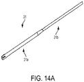
- FIG. 14A illustrates another exemplary embodiment of an actuation shaft 21.
- the actuation shaft 21 can be used as an actuation shaft in the surgical devices described herein.
- the actuation shaft 21 includes a distal elongate member 21a and a proximal elongate member 21b that are monolithically formed.
- the actuation shaft 21 can include a single cylindrical rod defining the distal elongate member 21a and the proximal elongate member 21b. A distal portion of the cylindrical rod being flattened (e.g., by cold forming) and trimmed to define the distal elongate member 21a.
- the first and second actuation shafts can be operatively connected to the device's second actuator 14 to facilitate articulation of the end effector 8.
- the first and second actuation shafts can be operatively connected to the device's second actuator 14 in a variety of ways.
- the device 2 can include a first stabilizing member 35a configured to couple the first actuation shaft to the second actuator 14, and can include a second stabilizing member 35b configured to couple the second actuation shaft to the second actuator 14.
- the first and second stabilizing members 35a, 35b can have a variety of configurations, but in an exemplary embodiment, they are the same as one another.
- the first stabilizing member 35a can include a first pair of washers 33a and a first clip 31a coupled thereto.
- the first pair of washers 33a can be ring-shaped, and the first clip 31a can be sandwiched therebetween, as in this illustrated embodiment.
- the first clip 31a can be configured to clip to the first tube 40a of the first actuation shaft, as shown in FIG. 17 .
- the first tube 40a can have a notch (not shown) formed therein configured to receive the first clip 31a therein, as in this illustrated embodiment.
- the structural stability of the first proximal elongate member 36a positioned within the first tube 40a can thus be maintained since the first tube 40a instead of the first proximal elongate member 36a can directly connect to the first clip 31a.
- the third actuation shaft can be configured to facilitate opening and closing of the jaws 12a, 12b and can include a third proximal elongate member 36c, a third distal elongate member 38c attached to the third proximal elongate member 36c, and a third elongate tube 40c (shown in FIGS. 9-11 ) having an inner lumen in which the third proximal elongate member 36c can be disposed.
- the third actuation shaft can be operatively connected to the first actuator 13 in a way such that actuation of the first actuator 13, e.g., movement of the handle 13, can cause opening and closing of the end effector 8. Movement of the handle 13 from an open position shown in FIGS.
- FIG. 10 in which the end effector 8 is open, to a closed position shown in FIG. 10 , in which the end effector 8 is closed, can be achieved by moving the handle 13 toward the main housing 32 can cause the third actuation shaft to move proximally, as shown by the proximal movement of the third actuation shaft's third tube 40c from FIG. 9 to FIG. 10 .
- movement of the handle 13 from the closed position of FIG. 10 to the open position of FIG. 9 can cause the end effector 8 to open.
- the third actuation shaft can be operatively connected to the first actuator 13 in a variety of ways, such as by using a stabilizing member (not shown) similar to the stabilizing members described herein.
- the fourth actuation shaft can be configured to facilitate movement of the cutting element 26 through the end effector 8 and can include a fourth proximal elongate member 36d, a fourth distal elongate member 38d attached to the fourth proximal elongate member 36d, and a fourth elongate tube (obscured in the Figures) having an inner lumen in which the fourth proximal elongate member 36d can be disposed.
- the fourth actuation shaft can be operatively connected to the fourth actuator 18 such that actuation of the fourth actuator 18 can be configured to cause movement of the fourth actuation shaft and thereby move the cutting element 26 along the end effector 8.
- the fourth actuation shaft can be operatively connected to the fourth actuator 18 in a variety of ways.
- the device 2 can include a third stabilizing member 35d configured to couple the fourth actuation shaft to the fourth actuator 18.
- the third stabilizing member 35d can be configured similar to the stabilizing members described herein, and can include a third pair of washers 33c and a third clip 31c coupled thereto that can be configured to clip to the fourth tube 40d of the fourth actuation member.
- the fourth tube 40d can have a notch (not shown) formed therein configured to receive the third clip 31c therein, as in this illustrated embodiment.
- the structural stability of the fourth proximal elongate member 36d positioned within the fourth tube 40d can thus be maintained since the fourth tube 40d instead of the fourth proximal elongate member 36d can directly connect to the third clip 31c.
- the outer shell 34 can be configured to stabilize movement of the actuation shafts during actuation of various actuators.
- the outer shell 34 can include a plurality of inner lumens 34a, 34b, 34c, 34d, 34e extending therethrough, as in this illustrated embodiment.
- the inner lumens 34a, 34b, 34c, 34d, 34e can be isolated from one another, as in this illustrated embodiment, which can help allow elements disposed in each of the inner lumens 34a, 34b, 34c, 34d, 34e to have different loads without affecting others of the elements and/or can help allow elements disposed in each of the inner lumens 34a, 34b, 34c, 34d, 34e to simultaneously move in different directions.
- a number of the inner lumens 34a, 34b, 34c, 34d, 34e can equal a number of actuator shafts, which in this illustrated embodiment is five, such that each of the actuator shafts can be disposed in its own one of the inner lumens 34a, 34b, 34c, 34d, 34e.
- the outer shell 34 can include a number of inner lumens less than a number of actuator shafts. The outer shell 34 can be configured to help protect the actuation shafts from an external environment along a longitudinal length of the outer shell 34.
- the first, second, third, and fourth actuation shafts can be configured to longitudinally translate within their respective ones of the inner lumens 34a, 34b, 34c, 34d, proximally and distally, in response to actuation of their respective ones of the first, second, third, and fourth actuators 13, 14, 16, 18.
- the first and second actuation shafts configured to facilitate articulation can be slidably seated in ones of the inner lumens 34a, 34b on opposite sides (e.g., left and rights sides) of the outer shell 34, which can facilitate articulation of the end effector 8 in opposite directions (e.g., left and right).
- the proximal elongate members 36a, 36b, 36c, 36d can be configured to be located in proximal regions of their respective inner lumens 34a, 34b, 34c, 34 and extend out a proximal end 34p of the outer shell 34
- the distal elongate members 38a, 38b, 38c, 38d can be configured to be located in distal regions of their respective inner lumens 34a, 34b, 34c, 34 and extend out a distal end 34s of the outer shell 34.
- connection areas between the first elongate members 36a, 38b, the second elongate members 36b, 38b, the third elongate members 36c, 38c, and the fourth elongate members 36d, 38d can be located within the outer shell 34. This can help protect the connection areas from any inadvertent wear or damage.
- the device 2 can include a bend region 41 configured to facilitate articulation of the end effector 8.
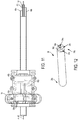
- the bend region can include a flexible outer shell 43, shown in FIGS. 3 and 8 , and shown in FIG. 13 as a standalone element.
- the flexible outer shell 43 can, as a flexible member, be configured to flex or bend without cracking, breaking, or otherwise becoming damaged, which can facilitate articulation of the end effector 8.
- the flexible outer shell 43 can have an inner lumen 43i extending therethrough, an upper spine 43u extending longitudinally therealong, a lower spine 43w extending longitudinally therealong, and a plurality of spaced ribs 43r extending between the upper and lower spines 43u, 43w on either side (e.g., left and right sides) of the flexible outer shell 43.
- the first, second, third, and fourth actuation shafts and the RF cable 39 can each extend through the inner lumen 43i of the flexible outer shell 43, as shown in FIGS. 3 and 8 .
- Exemplary embodiments of flexible outer shells are further described in U.S. Pat. Pub. No. 2012/0078247 entitled “Articulation Joint Features For Articulating Surgical Device” filed on September 19 2011, and in U.S. App. No. [ ] entitled “Flexible Neck For Surgical Instruments” filed on even date herewith [Atty. Dkt. No. 47364-157F01US (END7617USNP], which are hereby incorporated by reference in their entireties.
- the second actuation shaft is located more proximally than the first actuation shaft, as shown by the more proximal position of the second tube 40b as compared to the first tube 40a.
- the end effector 8 is accordingly articulated to the left, e.g., articulated in the second direction D2 (see FIG. 3 ), with the first and second distal elongate members 38a, 38b and the flexible outer shell 43 bent in the bend region 41, since the second actuation shaft is tensioned proximally, and is hence pulling on the left side of the end effector 8 to urge articulation to the left, and since the first actuation shaft is tensioned distally, and is hence pushing on the right side of the end effector 8 to urge articulation to the left.
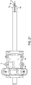
- the proximal movement of the second drum 44b has caused the second actuation shaft operatively connected thereto to correspondingly move proximally, as shown by the more proximal position of the second tube 40b in FIG. 21 as compared to FIG. 20 .
- the end effector 8 has accordingly moved to the left, e.g., in the first direction D2 (see FIG. 3 ), from its position in FIG. 20 .
- the RF cable 39, the third actuation shaft, and the fourth actuation shaft have not moved in response to the actuation of the second actuator 14 between FIGS. 20 and 21 .
- FIGS. 39-41 illustrate another embodiment of an outer shell 400 configured to stabilize movement of actuation shafts during actuation of various actuators.
- the outer shell 400 can have a cross-sectional shape defining a plurality of longitudinal channels 402a, 402b, 402c, 402d extending along the outer shell 400.
- the channels 402a, 402b, 402c, 402d can generally be used similar to the lumens 34a, 34b, 34c, 34d, 34e of the outer shell 34 in the embodiment of FIG. 12 and be configured to slidably receive actuation shafts therein.
- the outer shell 400 can include at least one inner lumen 404 extending therethrough, which can also each be configured to slidably receive an actuation shaft therein.
- each of the guide members 408a, 408b, 408c, 408d can include attachment mechanisms 412a, 412b, 412c, 412d at opposed proximal and distal ends thereof (the first and fourth proximal attachment mechanisms 412a, 412c are not shown in FIGS. 39-41 ).
- the attachment mechanisms 412a, 412b, 412c, 412d can be configured to be crimped to their associated one of the actuation shafts 406, 406b, 406c, 406d, thereby securing the actuation shafts 406, 406b, 406c, 406d thereto.
- the outer member 502 can have at least one opening 508 formed therein, which in this illustrated embodiment includes at least one longitudinal slot.
- a number of the openings 508 can equal a number of the channels 504a, 504b, 504c, 504d such that each one of the openings 508 is associated with one of the channels 504a, 504b, 504c, 504d and accordingly with one of the actuation shafts 510a, 510b, 510c, 510d.
- FIGS. 25-35 One embodiment of a method of manufacturing a surgical device is described with reference to the device of FIGS. 25-35 , but any of the surgical devices disclosed herein can be similarly assembled.
- the device can be assembled as shown in FIGS. 27 and 32 in any of a variety of ways, as will be appreciated by a person of skill in the art.
- Distal ends of the first and second actuation shafts can be attached to the end effector 106, such as shown in FIG.
- the distal movement of the first and second tubes 128a, 128b can push the first and second tubes 128a, 128b against the actuation mechanism, e.g., inside the second actuator's inner lumen, so as to tightly engage the first and second actuation shafts with the second actuator 114.
- the proximal movement of the first and second proximal elongate members 124a, 124b can pull on the first and second distal elongate members 126a, 126b so as straighten and take out tolerance.
- a set load can thereby be achieved by the distally directed force applied to the first and second tubes 128a, 128b and the proximally directed force applied to the first and second actuation shafts.
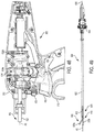
- the handle portion 602 can include a main housing 612, which can house a variety of elements therein and can have some elements accessible outside thereof, such as a first actuator 616 configured to effect the opening and closing of the opposed jaws 608a, 608b, a second actuator 614 configured to effect articulation of the end effector 606, a third actuator (not shown in FIGS. 48-54 ) configured to rotate the shaft assembly 604 and the end effector 606 about a longitudinal axis A5 of the shaft assembly 604, a fourth actuator 618 configured to translate a cutting element (obscured in FIGS. 48-54 ) along the end effector 606, and a fifth actuator 620 configured to turn on and off the application of energy, which includes RF energy in this illustrated embodiment.
- a first actuator 616 configured to effect the opening and closing of the opposed jaws 608a, 608b
- a second actuator 614 configured to effect articulation of the end effector 606
- a third actuator (not shown in FIGS. 48-54 ) configured
- the second actuator 614 configured to effect articulation of the end effector 606 can be operatively connected to an actuation mechanism, which can include first and second drums 634a, 634b.
- the second actuator 614 and the first and second drums 634a, 634b can be threadably engaged, as shown in FIGS. 48 and 49.
- FIG. 49 illustrates the end effector 606 in an unarticulated position, e.g., at a zero angle relative to the longitudinal axis A5.
- the outer shell 622 can be made from a composite material, which can facilitate the pultrusion process.
- the composite material can have a relatively high modulus, which can facilitate the pultrusion process.
- the modulus of the composite material can be in a range of about four million to about eight million, e.g., about seven million.
- the device can include a first stabilizing member 626a configured to couple the first actuation shaft 624a to the second actuator 614, a second stabilizing member 626b configured to couple the second actuation shaft 624b to the second actuator 614, a third stabilizing member 626c configured to couple the third actuation shaft 624c to the first actuator 616, a fourth stabilizing member 626d configured to couple the fourth actuation shaft 624d to the fourth actuator 618, and a fifth stabilizing member 626e including configured to couple the fifth actuation shaft 624e to the fifth actuator 620.
- FIG. 55 illustrates another embodiment of an outer shell 700 including a plurality of inner lumens 702a, 702b, 702c, 702d, 702e.
- the outer shell 700 can be used in any of the surgical devices described herein and can generally be configured and used similar to other outer shells described herein.
- the outer shell 700 has a splined outer surface, and each of the inner lumens 702a, 702b, 702c, 702d, 702e are defined by a splined surface.
- the splined surfaces can facilitate cleaning and sterilization using a process such as ethylene oxide.
- the outer shell 700 of this illustrated embodiment can be formed in a variety of ways, such as pultrusion or extrusion.
- the embodiment of the outer shell 622 illustrated in FIG. 53 has an unsplined outer surface, and each of its inner lumens are defined by an unsplined surface.
- reconditioning of a device can utilize a variety of techniques for disassembly, cleaning/replacement, and reassembly. Use of such techniques, and the resulting reconditioned device, are all within the scope of the present application.
- components of the invention described herein will be processed before use.
- a new or used instrument is obtained and if necessary cleaned.
- the instrument can then be sterilized.
- the instrument is placed in a closed and sealed container, such as a plastic or TYVEK bag.
- the container and instrument are then placed in a field of radiation that can penetrate the container, such as gamma radiation, x-rays, or high-energy electrons.
- the radiation kills bacteria on the instrument and in the container.
- the sterilized instrument can then be stored in the sterile container.
- the sealed container keeps the instrument sterile until it is opened in the medical facility.
- the device is sterilized. This can be done by any number of ways known to those skilled in the art including beta or gamma radiation, ethylene oxide, steam, and a liquid bath (e.g., cold soak).
- a liquid bath e.g., cold soak.
- An exemplary embodiment of sterilizing a device including internal circuitry is described in more detail in U.S. Pat. Pub. No. 2009/0202387 filed February 8, 2008 and entitled "System And Method Of Sterilizing An Implantable Medical Device.” It is preferred that device, if implanted, is hermetically sealed. This can be done by any number of ways known to those skilled in the art.
Landscapes
- Health & Medical Sciences (AREA)
- Life Sciences & Earth Sciences (AREA)
- Surgery (AREA)
- Engineering & Computer Science (AREA)
- Medical Informatics (AREA)
- Veterinary Medicine (AREA)
- Biomedical Technology (AREA)
- Heart & Thoracic Surgery (AREA)
- Nuclear Medicine, Radiotherapy & Molecular Imaging (AREA)
- Molecular Biology (AREA)
- Animal Behavior & Ethology (AREA)
- General Health & Medical Sciences (AREA)
- Public Health (AREA)
- Ophthalmology & Optometry (AREA)
- Physics & Mathematics (AREA)
- Plasma & Fusion (AREA)
- Otolaryngology (AREA)
- Surgical Instruments (AREA)
Abstract
Description
- The present disclosure relates generally to methods and devices for actuating surgical instruments.
- Minimally invasive surgical techniques such as endoscopies and laparoscopies are often preferred over traditional surgeries because the recovery time, pain, and surgery-related complications are typically less with minimally invasive surgical techniques. Rather than cut open large portions of the body in order to access inner cavities, surgeons either rely on natural orifices of the body or create one or more small orifices in which surgical instruments can be inserted to allow surgeons to visualize and operate at the surgical site.
- Some minimally invasive procedures can require that a working end of a device, which is inserted into the body, be articulated to angularly reorient the working end relative to the tissue. During such a procedure, for example, it is often necessary to reorient the working end such that jaws at the working end are at an angle relative to a shaft of the device, while still allowing the jaws to open and close to grasp tissue. Such angulation is often achieved via one or more cables attached to the jaws. However, with current cable driven jaw reorienting actuation systems, after articulation of the device, the cables are subject to high tensions which makes opening and closing of the jaws with precision difficult.
- Accordingly, there remains a need for improved methods and devices for actuating surgical instruments.
- In one embodiment, a surgical device is provided that in one embodiment includes a handle, a shaft assembly, and an end effector. The handle can have an actuation mechanism coupled thereto. The shaft assembly can extend distally from the handle, can include an outer elongate shell defining an inner lumen, and can include first and second elongate members extending longitudinally within the inner lumen. The end effector can be coupled to a distal end of the shaft assembly. The actuation mechanism can be configured to be actuated by a user so as to simultaneously cause a first force to be applied to one of the first and second elongate members, and thereby cause the one of the first and second elongate members to slidably translate proximally and longitudinally within the inner lumen, and cause a second force to be applied to the other of the first and second elongate members, and thereby cause the other of the first and second elongate members to slidably translate distally and longitudinally within the inner lumen. The translation of the first and second elongate members can cause articulation of the end effector.
- The surgical device can vary in any number of ways. For example, the shaft assembly can include first and second elongate tubes. The first elongate member can be positioned within the first elongate tube in a fixed position relative thereto. The second elongate member can be positioned within the second elongate tube in a fixed position relative thereto. The actuation mechanism can be configured to move the first and second elongate tubes in response to the actuation of the actuation mechanism, thereby causing the translation of the first and second elongate members. The first elongate member can be attached to the first elongate tube via one of welding and crimping, and the second elongate member can be attached to the second elongate tube via one of welding and crimping. Additionally or alternatively, the first and second elongate tubes in a default state of the surgical device can be tensioned in a distal direction and the first and second elongate members in the default state can be tensioned in a proximal direction, and/or the surgical device can include first and second stabilizing members. The first stabilizing member can be attached to the first elongate tube, the second stabilizing member can be attached to the second elongate tube, and the actuation of the actuation mechanism can be configured to simultaneously longitudinally translate the first stabilizing member, thereby causing the longitudinal translation of the first elongate member, and longitudinally translate the second stabilizing member, thereby causing the longitudinal translation of the second elongate member. The surgical device can include a second actuation mechanism configured to be actuated by the user so as to rotate the first and second stabilizing members about a longitudinal axis of the outer elongate shell so as to cause rotation of the end effector about the longitudinal axis.
- For another example, the first elongate member can include a first rigid elongate rod, and the second elongate member can include a second rigid elongate rod. The shaft assembly can include a first flexible elongate band having a proximal end attached to a distal end of the first rigid elongate rod, and the second elongate member can include a second flexible elongate band having a proximal end attached to a distal end of the second rigid elongate rod. The first and second flexible elongate bands can be configured to bend during the articulation of the end effector.
- For still another example, the surgical device can include first and second stabilizing members. The first stabilizing member can be attached to the first elongate member via one of welding, crimping, and interference fit. The second stabilizing member can be attached to the second elongate member via one of welding, crimping, and interference fit. The actuation of the actuation mechanism can be configured to simultaneously longitudinally translate the first stabilizing member, thereby causing the longitudinal translation of the first elongate member, and longitudinally translate the second stabilizing member, thereby causing the longitudinal translation of the second elongate member.
- For yet another example, the surgical device can include a bend region at a distal portion of the shaft assembly. The shaft assembly can be configured to bend at the bend region so as to articulate the end effector. The first elongate member can include a first rigid elongate rod, the second elongate member can include a second rigid elongate rod, and the shaft assembly can include first and second flexible elongate bands each spanning the bend region. The first elongate band can have a proximal end attached to a distal end of the first rigid elongate rod. The second elongate member can include a second flexible elongate band having a proximal end attached to a distal end of the second rigid elongate rod. The first and second flexible elongate bands can be configured to bend in the bend region during the articulation of the end effector.
- For still another example, the actuation mechanism can include first and second drums. The first drum can be coupled to the first elongate member, the second drum can be coupled to the second elongate member, and the actuation of the actuation mechanism can be configured to simultaneously move the first drum in a first direction and thereby apply the first force and cause the longitudinal translation of the first elongate member, and move the second drum in a second direction and thereby apply the second force and cause the longitudinal translation of the second elongate member. The second direction can be opposite to the first direction. The actuation mechanism can be configured to continuously rotate 360° about the longitudinal axis. During the continuous 360° rotation of the actuation mechanism, the one of the first and second elongate members can be configured to first translate proximally and longitudinally within the inner lumen and the other of the first and second elongate members can be configured to translate distally and longitudinally within the inner lumen, and then the one of the first and second elongate members can be configured to translate distally and longitudinally within the inner lumen and the other of the first and second elongate members can be configured to translate proximally and longitudinally within the inner lumen.
- For another example, the first and second elongate members in a resting state can be tensioned at a non-zero load.
- For yet another example, the actuation mechanism includes one of a rotatable knob, a slidable lever, and a movable handle.
- In another aspect, a method of assembling the surgical device is provided that in one embodiment includes advancing the first elongate member into a first passageway of a first tube of the shaft assembly, coupling the first elongate member to the end effector, and with the first elongate member coupled to the end effector and within the first passageway, tensioning the first elongate member in a distal direction and tensioning the first tube in a proximal direction so that the first tube pushes proximally against the actuation mechanism and so that the first elongate member and the first tube are simultaneously tensioned. The method can include attaching the tensioned first elongate member to the tensioned first tube so that the tensioned first elongate member and the tensioned first tube are in a fixed position relative to one another. The method can include advancing the second elongate member into a second passageway of a second tube of the shaft assembly, coupling the second elongate member to the end effector, and with the second elongate member coupled to the end effector and within the second passageway, simultaneously tensioning the second elongate member in the distal direction and tensioning the second tube in the proximal direction so that the second tube pushes proximally against the actuation mechanism and so that the second elongate member and the second tube are simultaneously tensioned. The method can include attaching the tensioned second elongate member to the tensioned second tube so that the tensioned second elongate member and the tensioned second tube are in a fixed position relative to one another.
- The method can have any number of variations. For example, the first and second elongate members and the first and second tubes can be tensioned from distal ends thereof. For another example, the method can include, prior to the simultaneous tensioning of the first elongate member and the first tube, attaching a proximal end of a first flexible elongate band to a distal end of the first elongate member. The method can include, prior to the simultaneous tensioning of the second elongate member and the second tube, attaching a proximal end of a second flexible elongate band to a distal end of the second elongate member. The method can include attaching a distal end of the first flexible elongate band to the end effector, and attaching a distal end of the second flexible elongate band to the end effector.
- In another embodiment, a surgical device is provided that includes an actuation mechanism, a shaft assembly, and an end effector. The shaft assembly can extend distally from the handle, can include an outer elongate shell defining an inner lumen, can include a first rigid elongate member extending longitudinally within the inner lumen, and can include a first flexible elongate member extending longitudinally within the inner lumen. The first flexible elongate member can have a proximal end thereof attached to a distal end of the first rigid elongate member. The end effector can be attached to a distal end of the first flexible elongate member. The actuation mechanism can be configured to be actuated by a user so as to cause the first rigid elongate member and the first flexible elongate member to slidably translate longitudinally within the inner lumen. The translation of the first rigid elongate member and the first flexible elongate member can cause actuation of the end effector. The actuation of the end effector can include one of moving the end effector between open and closed positions, articulating the end effector, and translating a cutting element along the end effector.
- The surgical device can have any number of variations. For example, the surgical device can include a handle. The handle can have the actuation mechanism coupled thereto. The shaft assembly can extend distally from the handle.
- In another aspect, a method of assembling a surgical device is provided that in one embodiment includes slidably adjusting a position of a first elongate member within a first inner lumen extending through a first tubular member, slidably adjusting a position of a second elongate member within a second inner lumen extending through a second tubular member, coupling an end effector to the first and second elongate members, and coupling an actuation mechanism to the first and second tubular members. The end effector can be configured to manipulate tissue. The method can include, after adjusting the position of the first elongate member, coupling the first elongate member to the end effector, and coupling an actuation mechanism to the first and second tubular members, moving the first elongate member in a proximal direction and moving the first tubular member in a distal direction so as to achieve a first tension load. The method can include, at the achieved first tension load, securing the first elongate member and the first tubular member in a fixed position relative to one another. The method can include, after adjusting the position of the second elongate member, coupling the second elongate member to the end effector, and coupling an actuation mechanism to the first and second tubular members moving the second elongate member in the proximal direction and moving the second tubular member in the distal direction so as to achieve a second tension load. The method can include, at the achieved second tension load, securing the second elongate member and the second tubular member in a fixed position relative to one another. The actuation mechanism coupled to the first and second tubular members can be configured to be selectively actuated so as to cause the first elongate member and the first tube to move as a unit in one of the proximal and distal directions and to cause the second elongate member and the second tube to move as a unit in the other of the proximal and distal directions, thereby causing articulation of the end effector.
- The method can vary in any number of ways. For example, securing the first elongate member and the first tubular member in the fixed position relative to one another can include one of crimping the first elongate member and the first tubular member together and welding the first elongate member and the first tubular member together. For another example, the method can include securing a distal end of a first rigid rod to a proximal end of a first flexible band to form the first elongate member, securing a distal end of the first flexible band to the end effector, securing a distal end of a second rigid rod to a proximal end of a second flexible band to form the second elongate member, and securing a distal end of the second flexible band to the end effector. The first band can be configured to move with the first elongate member and the first tube as a unit in the one of the proximal and distal directions, and the second band can be configured to move with the second elongate member and the second tube as a unit in the other of the proximal and distal directions.
- This invention will be more fully understood from the following detailed description taken in conjunction with the accompanying drawings, in which:
-
FIG. 1 is a side view of one embodiment of a surgical device; -
FIG. 2 is a side view of a distal portion of the surgical device ofFIG. 1 ; -
FIG. 3 is a perspective view of a distal portion of the surgical device ofFIG. 1 ; -
FIG. 4 is a side, partially transparent view of a proximal portion of the surgical device ofFIG. 1 ; -
FIG. 5 is a perspective view of a proximal portion of the surgical device ofFIG. 1 with select elements of the device omitted for clarity of illustration; -
FIG. 6 is a perspective view of a distal portion of the surgical device ofFIG. 1 with a flexible outer shell of the device omitted for clarity of illustration; -
FIG. 7 is a another perspective view of the distal portion of the surgical device ofFIG. 6 ; -
FIG. 8 is a perspective, partial view of a flexible outer shell and actuation shafts of the device ofFIG. 1 ; -
FIG. 9 is a side, partially transparent view of a proximal portion of the surgical device ofFIG. 1 with a movable handle thereof in an open position and with select elements of the device omitted for clarity of illustration; -
FIG. 10 is a side, partially transparent view of the proximal portion of the surgical device ofFIG. 9 with select elements of the device omitted for clarity of illustration and with the movable handle thereof in a closed position; -
FIG. 11 is a side view of an actuation mechanism and actuation shafts of the surgical device ofFIG. 1 in a first position; -
FIG. 12 is a perspective view of an outer elongate shaft of the surgical device ofFIG. 1 ; -
FIG. 13 is a perspective view of the flexible outer shell of the surgical device ofFIG. 1 ; -
FIG. 14 is a perspective view of an actuator of the surgical device ofFIG. 1 ; -
FIG. 14A is a perspective view of a distal portion of one embodiment of an actuation shaft; -
FIG. 15 is a side, partial view of a handle portion of the surgical device ofFIG. 1 with select elements of the device omitted for clarity of illustration; -
FIG. 16 is a perspective, partial view of the handle portion of the surgical device ofFIG. 1 with select elements of the device omitted for clarity of illustration; -
FIG. 17 is another perspective, partial view of the handle portion of the surgical device ofFIG. 1 with select elements of the device omitted for clarity of illustration; -
FIG. 18 is a perspective, partial view of a proximal portion of the surgical device ofFIG. 1 with select elements of the device omitted for clarity of illustration; -
FIG. 19 is a side view of the actuation mechanism and actuation shafts ofFIG. 11 moved from the first position to a second position; -
FIG. 20 is a side view of the actuation mechanism and actuation shafts ofFIG. 19 moved from the second position to a third position; -
FIG. 21 is a side view of the actuation mechanism and actuation shafts ofFIG. 20 moved from the third position to a fourth position; -
FIG. 22 is a perspective view of a distal portion of the surgical device ofFIG. 1 with first and second actuation shafts of the device in a first position and with select elements of the device omitted for clarity of illustration; -
FIG. 23 is a perspective view of a distal portion of the surgical device ofFIG. 22 with select elements of the device omitted for clarity of illustration and with the first and second actuation shafts of the device moved from the first position to a second position; -
FIG. 24 is a perspective view of a distal portion of the surgical device ofFIG. 23 with select elements of the device omitted for clarity of illustration and with the first and second actuation shafts of the device moved from the second position to a third position; -
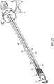
FIG. 25 is a perspective view of a proximal portion of another embodiment of a surgical device with select elements of the device omitted for clarity of illustration; -
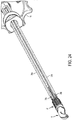
FIG. 26 is a perspective view of a portion of the surgical device ofFIG. 25 with select elements of the device omitted for clarity of illustration; -
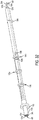
FIG. 27 is a perspective view of another portion of the surgical device ofFIG. 25 with select elements of the device omitted for clarity of illustration; -
FIG. 28 is a cross-sectional perspective view of another portion of the surgical device ofFIG. 25 with select elements of the device omitted for clarity of illustration; -
FIG. 29 is an enlarged view of a partial area of the portion of the surgical device ofFIG. 28 ; -
FIG. 30 is a perspective, partially transparent view of a distal portion of the surgical device ofFIG. 25 with an outer elongate shaft of the device omitted for clarity of illustration; -
FIG. 31 is a top view of a distal portion of the surgical device ofFIG. 25 showing an end effector of the device in an unarticulated position and in an articulated position; -
FIG. 32 is a perspective view of yet another portion of the surgical device ofFIG. 25 with select elements of the device omitted for clarity of illustration; -
FIG. 33 is an enlarged, partially transparent view of a partial area of the portion of the surgical device ofFIG. 32 ; -
FIG. 34 is a perspective view of select elements of the portion of the surgical device ofFIG. 32 ; -
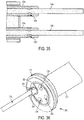
FIG. 35 is a side, cross-sectional view of select elements in a distal portion of the portion of the surgical device ofFIG. 32 ; -
FIG. 36 is a perspective view of a portion of another embodiment of a surgical device with an actuation shaft of the device secured to a stabilizing member of the device; -
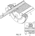
FIG. 37 is a perspective, cross-sectional view of the portion of the surgical device ofFIG. 36 with the actuation shaft not being secured to the stabilizing member, with an inset showing a cross-sectional schematic view; -
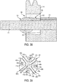
FIG. 38 is a side, cross-sectional view of a portion of yet another embodiment of a surgical device; -
FIG. 39 is a schematic, cross-sectional view of a portion of still another embodiment of a surgical device; -
FIG. 40 is a side view of the portion of the surgical device ofFIG. 39 ; -
FIG. 41 is a perspective view of select element of the surgical device ofFIG. 39 ; -
FIG. 42 is a perspective view of a portion of another embodiment of a surgical device; -
FIG. 43 is another perspective view of the portion of the surgical device ofFIG. 42 ; -
FIG. 44 is a perspective of an outer member of the surgical device ofFIG. 42 ; -
FIG. 45 is a cross-sectional view of an inner member of the surgical device ofFIG. 42 ; -
FIG. 46 is a perspective of a block of the surgical device ofFIG. 42 ; -
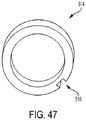
FIG. 47 is a perspective of a washer of the surgical device ofFIG. 42 ; -
FIG. 48 is a side, partially transparent view of a portion of another embodiment of a surgical device with select elements of the device omitted for clarity of illustration; -
FIG. 49 is a side view of another portion of the surgical device ofFIG. 48 with select elements of the device omitted for clarity of illustration; -
FIG. 50 is a perspective view of yet another portion of the surgical device ofFIG. 48 with select elements of the device omitted for clarity of illustration; -
FIG. 51 is a perspective view of the portion of the surgical device ofFIG. 50 with select elements of the device omitted for clarity of illustration; -
FIG. 52 is a perspective view of a portion of the device ofFIG. 50 ; -
FIG. 53 is a cross-sectional view of an outer shell of the portion of the surgical device ofFIG. 51 ; -
FIG. 54 is a cross-sectional view of the portion of the surgical device ofFIG. 50 ; and -
FIG. 55 is a cross-sectional view of another embodiment of an outer shell. - Certain exemplary embodiments will now be described to provide an overall understanding of the principles of the structure, function, manufacture, and use of the devices and methods disclosed herein. One or more examples of these embodiments are illustrated in the accompanying drawings. Those skilled in the art will understand that the devices and methods specifically described herein and illustrated in the accompanying drawings are non-limiting exemplary embodiments and that the scope of the present invention is defined solely by the claims. The features illustrated or described in connection with one exemplary embodiment may be combined with the features of other embodiments. Such modifications and variations are intended to be included within the scope of the present invention.
- Further, in the present disclosure, like-named components of the embodiments generally have similar features, and thus within a particular embodiment each feature of each like-named component is not necessarily fully elaborated upon. Additionally, to the extent that linear or circular dimensions are used in the description of the disclosed systems, devices, and methods, such dimensions are not intended to limit the types of shapes that can be used in conjunction with such systems, devices, and methods. A person skilled in the art will recognize that an equivalent to such linear and circular dimensions can easily be determined for any geometric shape. Sizes and shapes of the systems and devices, and the components thereof, can depend at least on the anatomy of the subject in which the systems and devices will be used, the size and shape of components with which the systems and devices will be used, and the methods and procedures in which the systems and devices will be used.
- Various exemplary methods and devices for actuating surgical instruments are provided. In general, a surgical device can include one or more actuation shafts configured to facilitate actuation of the device, e.g., articulation of an end effector of the device, opening and closing of jaws at a distal end of the device, moving a cutting element of the device, etc. In an exemplary embodiment, the device can include four actuation shafts, two actuation shafts to facilitate articulation of the device, one actuation shaft to facilitate opening and closing of jaws at a distal end of the device, and one actuation shaft to facilitate moving a cutting element of the device. In an exemplary embodiment, each of the one or more actuation shafts can include a distal elongate member and a proximal elongate member having a distal end attached to a proximal end of the distal elongate member. The proximal elongate member can be rigid, which can help ease insertion of the device into a patient's body directly or through an access device such as a trocar, can facilitate smooth, stable longitudinal translation of the actuation shaft to actuate the device, and/or can facilitate making actuation shafts in a variety of longitudinal lengths since the proximal elongate member can simply be cut to have a desired longitudinal length. The distal elongate member can be flexible, which can accommodate articulation of the device's end effector since the distal elongate member can bend during articulation. In at least some embodiments, each of the one or more actuation shafts can include a tubular member configured to seat the proximal elongate member therein. The tubular member can facilitate attachment of the actuation shaft to an actuator configured to be manually manipulated by a user to cause the desired actuation, e.g., articulation, jaw opening/closing, cutting element movement, etc., and/or can facilitate tensioning of the actuation shaft. Tensioning the actuation shaft can help account for a flexible distal portion of the actuation shaft (e.g., the flexible distal elongate member) by helping to prevent the device from sagging or being loose due to the flexibility of the flexible distal portion of the actuation shaft. The device sagging or being loose can make the device more difficult to advance into a patient because sagging and looseness adversely affects stability, can make the device more difficult to desirably position relative to a surgical target because sagging and looseness adversely affects stability, can inhibit the use of the device in surgical tasks such as otomy creation and tissue manipulation and grasping, and/or can make the device more difficult to actuate since increased force applied by a user can be necessary to overcome the sagging or looseness of the device.
- Various exemplary methods of manufacturing the surgical instruments described herein are provided. In general, a surgical device including at least one actuation shaft having a rigid proximal portion and a flexible distal portion (e.g., including a rigid proximal elongate member attached to a flexible distal elongate member) can be manufactured to reduce looseness or tolerance. The reduction can, in an exemplary embodiment, reduce the looseness or tolerance to substantially zero. A person skilled in the art will appreciate that looseness or tolerance may not be precisely zero but nevertheless be considered to be substantially zero due to, e.g., tolerances in measurement devices. The surgical device can thus be manufactured to neutralize tolerance arising from presence of the flexible distal portion. In an exemplary embodiment, the tolerance can be neutralized by simultaneously applying a distally-directed force to a tubular member of the actuation shaft so as to push the tubular member distally and applying a proximally-directed force to a rigid proximal elongate member of the actuation shaft, and accordingly to a flexible distal elongate member of the actuation shaft attached thereto, so as to pull the flexible distal elongate member and the rigid proximal elongate member proximally, thereby reducing sagging and looseness. The tensioned tube and the tensioned rigid proximal elongate member can then be attached together to maintain the load and achieve the reduced sagging and looseness in the assembled device. The proximally-directed force can be applied to the rigid proximal elongate member (and flexible distal elongate member attached thereto) after a distal end of the flexible distal elongate member has been attached to an end effector of the surgical device, which can facilitate the tensioning by holding the distal end of the flexible distal elongate member in a substantially fixed position during the tensioning. The distally-directed force can be applied to the tubular member after assembly of an actuator of the surgical device associated with the actuation shaft being tensioned, which can facilitate the tensioning by allowing a distal end of the tubular member to push against the actuator during the tensioning.
-
FIG. 1 illustrates one embodiment of asurgical device 2 that can include aproximal handle portion 4 having ashaft assembly 6 extending distally therefrom. As also shown inFIGS. 2 and3 , thedevice 2 can include a workingelement 8, also referred to herein as an "end effector," coupled to a distal end of theshaft assembly 6. Theend effector 8 can be coupled to theshaft assembly 6 at a pivot joint 10. A proximal end of theend effector 8 can be pivotally coupled to the joint 10 at the distal end of theshaft assembly 6. - The
end effector 8 can have a variety of sizes, shapes, and configurations. As shown inFIGS. 1-3 , theend effector 8, including the first andsecond jaws surgical device 2. Theend effector 8 in this illustrated embodiment includes a tissue grasper having a pair ofopposed jaws end effector 8 can have other configurations, e.g., scissors, a babcock, a retractor, etc. In an exemplary embodiment, theend effector 8 can be rigid. Theend effector 8 can include the first, top, orupper jaw 12a and the second, bottom, orlower jaw 12b pivotally connected together at the pivot joint 10. - One or both of the
first jaw 12a and thesecond jaw 12b can includespacers 30 on facing tissue engagement surfaces thereof. Thespacers 30 can be configured to maintain a minimum gap of space between thejaws jaws electrodes 24, discussed further below, from becoming damaged and/or from creating a closed circuit loop between thejaws jaws spacers 30 extending therefrom toward thebottom jaw 12b, as shown inFIG. 3 . In other embodiments, only the bottom jaw may include spacers, or both the top and bottom jaws may include spacers. - One or both of the
jaws electrodes 24, which can be configured to contact tissue positioned between thejaws electrodes 24 are arranged longitudinally along thebottom jaw 12b in this illustrated embodiment, but theelectrodes 24 can be arranged in any of a variety of ways on theupper jaw 12a and/or thelower jaw 12b. - The
handle portion 4 can have a variety of sizes, shapes, and configurations. Thehandle portion 4 can include amain housing 32, which can house a variety of elements therein and can have some elements accessible outside thereof, such as afirst actuator 13, asecond actuator 14, athird actuator 16, afourth actuator 18, and afifth actuator 20. - The
first actuator 13 can be configured to effect the opening and closing of theopposed jaws jaws jaws FIGS. 1-3 and6 are shown in the open position. As in this illustrated embodiment, theupper jaw 12a can be configured to move relative to thebottom jaw 12b, which can remain stationary relative to theshaft assembly 6, to effect the opening and closing of theend effector 8. In other embodiments, in order to effect opening and closing of the end effector, the bottom jaw can be configured to move relative to the upper jaw, or both the upper and lower jaws can be configured to move relative to the shaft assembly. - In an exemplary embodiment, the
first actuator 13 can include a gripper arm, also referred to herein as a "handle" and a "movable handle." Thehandle 13 can, in other embodiments, have different sizes, shapes, and configurations, e.g., no thumb rests, multiple finger loops, different arcuate shape, etc. As shown inFIGS. 1 ,4 , and5 , thehandle 13 can be pivotally attached to themain housing 32. Thehandle 13 can be configured to move toward and away from themain housing 32, thereby causing opening and closing of theend effector 8, as discussed further below. - The
second actuator 14 can be configured to effect articulation of theend effector 8, e.g., movement of bothjaws shaft assembly 6. The articulation can be independent of the opening and closing of thejaws end effector 8 inFIGS. 1-3 is shown in an unarticulated position, e.g., at a zero angle relative to the longitudinal axis A. Thesecond actuator 14 can be operatively connected to an actuation mechanism, which can be disposed within themain housing 32 and is discussed further below, such that actuation of thesecond actuator 14, e.g., manual movement thereof by a user, can cause articulation of theend effector 8. In an exemplary embodiment, thesecond actuator 14 can be configured to be actuated so as to cause thejaws FIG. 3 ) relative to the longitudinal axis A. - The
second actuator 14 can have a variety of sizes, shapes, and configurations. As in this illustrated embodiment, thesecond actuator 14 can include a rotatable knob. Rotation of thesecond actuator 14 in one direction (e.g., clockwise) can be configured to cause articulation of theend effector 8 in the first direction D1 (e.g., right) and rotation of thesecond actuator 14 in the opposite direction (e.g., counterclockwise) can be configured to cause articulation of theend effector 8 in the second direction D2 (e.g., left). Theknob 14 can be rigid. Theknob 16 can include a moveable ring, as shown inFIG. 5 . Theknob 14 can include one or more finger depressions on an exterior surface thereof, as in this illustrated embodiment. The finger depressions can facilitate manual movement of theknob 14 using one or more fingers seated in the finger depressions. As in this illustrated embodiment, the finger depressions can extend around an entire circumference of the knob's exterior surface. - The
third actuator 16 can be configured to rotate theshaft assembly 6 and theend effector 8 about the longitudinal axis A of theshaft assembly 6. Thethird actuator 16 includes a rotatable knob in this illustrated embodiment that can be rotated about the longitudinal axis A, but thethird actuator 16 can have a variety of other configurations, e.g., a lever, a button, a movable handle, etc. As in this illustrated embodiment, thethird actuator 16 can be configured to continuously and repeatedly rotate theshaft assembly 6 and theend effector 8 360° in both clockwise and counterclockwise directions. In other words, theshaft assembly 6 can be configured for unlimited bi-directional rotation. As will be appreciated by a person skilled in the art, theshaft assembly 6 and theend effector 8 can be rotated less than 360° as desired during performance of a surgical procedure (e.g., rotated 20°, rotated 90°, rotated 150°, etc.) and can be rotated more than 360° as desired during performance of a surgical procedure (e.g., rotated 450°, rotated 480°, rotated 720°, etc.). - The
fourth actuator 18 can be configured to translate a cutting element 26 (e.g., a knife, a blade, etc.) along theend effector 8. The cuttingelement 26 can be configured to cut tissue positioned between thejaws FIGS. 3 and6 , thejaws elongate slot 28 therein (the slot in theupper jaw 12a is obscured inFIGS. 3 and6 ) through which thecutting element 2 can be configured to slide. - As in this illustrated embodiment, the
surgical device 2 can be powered and be configured as an electrosurgical tool configured to apply energy to tissue, such as radiofrequency (RF) energy. Thehandle portion 4 can have apower cord 22 extending proximally therefrom that can be configured to supply electrical power to thedevice 2, such as by connecting to a generator, by plugging into an electrical outlet, etc. Thefifth actuator 20 can be configured to turn on and off the application of the energy, which can be delivered to tissue via theelectrodes 24. Thefifth actuator 20 includes a button in this illustrated embodiment, but thefifth actuator 20 can have other configurations, e.g., a knob, a lever, a movable handle, a switch, etc. In other embodiments, the surgical device can be unpowered, e.g., not be configured to apply energy to tissue. - The
shaft assembly 6 can have a variety of sizes, shapes, and configurations. Theshaft assembly 6 can have any longitudinal length, although in an exemplary embodiment it can be long enough to allow thehandle portion 4 to be manipulated outside a patient's body while theshaft assembly 6 extends through an opening in the body with theend effector 8 disposed within a body cavity, e.g., have a longitudinal length of about 33 cm. In this way, theend effector 8 can be easily manipulated when thedevice 2 is in use during a surgical procedure. Theshaft assembly 6 can have any diameter. For example, the shaft assembly's diameter can be less than or equal to about 15 mm, e.g., less than or equal to about 10 mm, less than or equal to about 7 mm, less than or equal to about 5 mm, etc., which can allow for insertion of theshaft assembly 6 through an minimally invasive access device, such as during a laparoscopic surgical procedure. Theend effector 8 mated to the shaft assembly's distal end can have a diameter equal to or less than the shaft assembly's diameter, at least when thejaws - As in this illustrated embodiment, the
shaft assembly 6 can include an outer elongate shaft 34 (also referred to herein an "outer shell") and at least one actuation shaft extending between thehandle portion 4 and theend effector 8. The one or more actuation shafts can be configured to facilitate articulation of theend effector 8, to facilitate opening/closing of theend effector 8, and/or to facilitate movement of the cuttingelement 26 along theend effector 8. As in this illustrated embodiment, thedevice 2 can include first and second actuation shafts configured to facilitate articulation of theend effector 8, a third actuation shaft configured to facilitate opening/closing of theend effector 8, and a fourth actuation shaft configured to facilitate movement of the cuttingelement 26 along theend effector 8. In other embodiments, a surgical device can include any combination of the actuation shafts configured to facilitate articulation of the end effector, opening/closing of the end effector, and movement of the cutting element along the end effector, e.g., only include the first and second actuation shafts; only include the fourth actuation shaft; include the first, second, and third actuation shafts; include the third and fourth actuation shafts; etc. The actuation shafts can each have relatively small diameters, which can facilitate their inclusion in a device configured to use in a minimally invasive surgical procedure. In an exemplary embodiment, the actuation shafts can each have a diameter of about 0.04 in. In an exemplary embodiment, theouter shell 34 can have a diameter in a range of about 0.2 in. to 0.221 in. A person skilled in the art will appreciate that an element may not have a diameter of a precisely value but nevertheless be considered to have a diameter of about that value due to, e.g., manufacturing tolerances. - As in this illustrated embodiment, each of the actuation shafts can include a distal elongate member and a proximal elongate member having a distal end attached to a proximal end of the distal elongate member. The distal end of the proximal elongate member can be attached to the proximal end of the distal elongate member in a variety of ways, such as by welding, crimping, gluing, threading, swaging, stamping, trapping, riveting, etc. In an exemplary embodiment, the distal end of the proximal elongate member can be attached to the proximal end of the distal elongate member by welding or crimping, which can be cost effective for manufacturing and/or which can be a relatively simple process during manufacturing. The proximal elongate member can be a rigid member (e.g., generally unable to flex or bend without cracking, breaking, or otherwise becoming damaged), and the distal elongate member can be a flexible member (e.g., generally able to flex or bend without cracking, breaking, or otherwise becoming damaged). The actuation shaft can be made from one or more materials such as titanium, stainless steel, a stranded cable, etc. The rigid and flexible members of the actuation shaft can be made from the same material or can be made from different materials. In an exemplary embodiment, the actuation shaft can have a yield strength in a range of about 40 to 200 ksi. The rigid nature of the proximal elongate member can facilitate stability of the
device 2, which can help ease insertion of thedevice 2 into a patient's body directly or through an access device such as a trocar. This property of the proximal elongate member can facilitate smooth, stable longitudinal translation of the actuation shaft relative to theouter shaft 34, discussed further below. The rigid nature of the proximal elongate member can facilitate making actuation shafts in a variety of longitudinal lengths for different surgical devices since the proximal elongate member can be cut to a desired longitudinal length, as discussed further below. The flexible nature of the distal elongate member can accommodate articulation of theend effector 8 since the distal elongate member can be configured to bend so as to facilitate articulation of theend effector 8 coupled thereto. As discussed further below, the actuation shaft having a rigid portion and a flexible portion can ease manufacturing of thedevice 2 since an entirely flexible actuation shaft need not be formed, such as by stamping, which is traditionally more expensive than methods to form a rigid member, such as molding or casting. The actuation shaft having a rigid portion and a flexible portion can ease manufacturing of surgical devices since distal elongate members can all be formed with a same longitudinal length and proximal elongate members can be formed at selected, different longitudinal lengths, thereby allowing formation of actuation shafts having different longitudinal lengths appropriate for use in different sized devices and/or reducing costs since it is traditionally more expensive to manufacture a flexible member for actuation of a surgical device than to form a rigid member for actuation of a surgical device. - The proximal and distal elongate members can have a variety of configurations. The proximal elongate member can be rigid, as mentioned above, and can include an elongate rod (as in this illustrated embodiment), an elongate band, etc. The distal elongate member can be flexible, as mentioned above, and can include an elongate rod, an elongate band (as in this illustrated embodiment), a cable, a wire, etc. The distal elongate member being a substantially planar band can help conserve real estate at a distal portion of the
device 2. A person skilled in the art will appreciate that a band may not be precisely planar but nevertheless be considered to be substantially planar due to, e.g., manufacturing tolerances. - As mentioned above, the
device 2 in this illustrated embodiment includes four actuation shafts, as shown inFIGS. 5-11 . The first actuation shaft can be configured to facilitate articulation of theend effector 8 and can include a first proximalelongate member 36a, a first distalelongate member 38a attached to the first proximalelongate member 36a, and a firstelongate tube 40a (shown inFIG. 11 ) attached to the first proximalelongate member 36a and having an inner lumen in which the first proximalelongate member 36a can be disposed. The second actuation shaft can be configured to facilitate articulation of theend effector 8 and can include a second proximalelongate member 36b, a second distalelongate member 38b attached to the second proximalelongate member 36b, and a secondelongate tube 40b (shown inFIG. 11 ) attached to the second proximalelongate member 36b and having an inner lumen in which the second proximalelongate member 36b can be disposed. The first and secondelongate tubes elongate members elongate tubes -
FIG. 14A illustrates another exemplary embodiment of anactuation shaft 21. Theactuation shaft 21 can be used as an actuation shaft in the surgical devices described herein. In this illustrated embodiment, theactuation shaft 21 includes a distalelongate member 21a and a proximal elongate member 21b that are monolithically formed. Theactuation shaft 21 can include a single cylindrical rod defining the distalelongate member 21a and the proximal elongate member 21b. A distal portion of the cylindrical rod being flattened (e.g., by cold forming) and trimmed to define the distalelongate member 21a. - Referring again to the embodiment of
FIG. 1 , the first and second actuation shafts can be operatively connected to the device'ssecond actuator 14 to facilitate articulation of theend effector 8. The first and second actuation shafts can be operatively connected to the device'ssecond actuator 14 in a variety of ways. As in this illustrated embodiment, as shown inFIGS. 16 and17 , thedevice 2 can include a first stabilizingmember 35a configured to couple the first actuation shaft to thesecond actuator 14, and can include a second stabilizingmember 35b configured to couple the second actuation shaft to thesecond actuator 14. The first and second stabilizingmembers member 35a can include a first pair ofwashers 33a and afirst clip 31a coupled thereto. The first pair ofwashers 33a can be ring-shaped, and thefirst clip 31a can be sandwiched therebetween, as in this illustrated embodiment. Thefirst clip 31a can be configured to clip to thefirst tube 40a of the first actuation shaft, as shown inFIG. 17 . Thefirst tube 40a can have a notch (not shown) formed therein configured to receive thefirst clip 31a therein, as in this illustrated embodiment. The structural stability of the first proximalelongate member 36a positioned within thefirst tube 40a can thus be maintained since thefirst tube 40a instead of the first proximalelongate member 36a can directly connect to thefirst clip 31a. Similar to the first stabilizingmember 35a, the second stabilizingmember 35b can include a first pair ofwashers 33b and asecond clip 31b coupled thereto that can be configured to clip to thesecond tube 40b of the second actuation shaft, as shown inFIGS. 16 and17 . Thesecond tube 40b can have a notch (not shown) formed therein configured to receive thesecond clip 31b therein, as in this illustrated embodiment. The structural stability of the second proximalelongate member 36b positioned within thesecond tube 40b can thus be maintained since thesecond tube 40b instead of the second proximalelongate member 36b can directly connect to thesecond clip 31b. The second pair ofwashers 33b can be ring-shaped, and thesecond clip 31b can be sandwiched therebetween, as in this illustrated embodiment. - The third actuation shaft can be configured to facilitate opening and closing of the
jaws elongate member 36c, a third distalelongate member 38c attached to the third proximalelongate member 36c, and a thirdelongate tube 40c (shown inFIGS. 9-11 ) having an inner lumen in which the third proximalelongate member 36c can be disposed. The third actuation shaft can be operatively connected to thefirst actuator 13 in a way such that actuation of thefirst actuator 13, e.g., movement of thehandle 13, can cause opening and closing of theend effector 8. Movement of thehandle 13 from an open position shown inFIGS. 5 and9 , in which theend effector 8 is open, to a closed position shown inFIG. 10 , in which theend effector 8 is closed, can be achieved by moving thehandle 13 toward themain housing 32 can cause the third actuation shaft to move proximally, as shown by the proximal movement of the third actuation shaft'sthird tube 40c fromFIG. 9 to FIG. 10 . Likewise, movement of thehandle 13 from the closed position ofFIG. 10 to the open position ofFIG. 9 can cause theend effector 8 to open. The third actuation shaft can be operatively connected to thefirst actuator 13 in a variety of ways, such as by using a stabilizing member (not shown) similar to the stabilizing members described herein. - The fourth actuation shaft can be configured to facilitate movement of the cutting
element 26 through theend effector 8 and can include a fourth proximalelongate member 36d, a fourth distalelongate member 38d attached to the fourth proximalelongate member 36d, and a fourth elongate tube (obscured in the Figures) having an inner lumen in which the fourth proximalelongate member 36d can be disposed. The fourth actuation shaft can be operatively connected to thefourth actuator 18 such that actuation of thefourth actuator 18 can be configured to cause movement of the fourth actuation shaft and thereby move the cuttingelement 26 along theend effector 8. The fourth actuation shaft can be operatively connected to thefourth actuator 18 in a variety of ways. As in this illustrated embodiment, as shown inFIGS. 16 and18 , thedevice 2 can include a third stabilizing member 35d configured to couple the fourth actuation shaft to thefourth actuator 18. The third stabilizing member 35d can be configured similar to the stabilizing members described herein, and can include a third pair of washers 33c and a third clip 31c coupled thereto that can be configured to clip to the fourth tube 40d of the fourth actuation member. The fourth tube 40d can have a notch (not shown) formed therein configured to receive the third clip 31c therein, as in this illustrated embodiment. The structural stability of the fourth proximalelongate member 36d positioned within the fourth tube 40d can thus be maintained since the fourth tube 40d instead of the fourth proximalelongate member 36d can directly connect to the third clip 31c. - The
fifth actuator 20 can be operatively connected to a conductive lead 39 (shown inFIGS. 5 ,9 , and10 and inFIG. 6 with a distal portion thereof absent to ease illustration of other parts of the device 2), which in this illustrated embodiment includes an RF cable, configured to be in electrical communication with thepower cord 22 and with theelectrodes 24. The actuation of thefifth actuator 20, e.g., pushing the button, can be configured to close a circuit and thereby allow power to be provided to theRF cable 39, which can accordingly allow power to be supplied to theelectrodes 24. - The outer
elongate shaft 34 of theshaft assembly 6, which is illustrated as a standalone element inFIG. 12 , can have a variety of sizes, shapes, and configurations. Theouter shell 34 can be configured to stabilize movement of the actuation shafts during actuation of various actuators. Theouter shell 34 can include a plurality ofinner lumens inner lumens inner lumens inner lumens inner lumens inner lumens outer shell 34 can include a number of inner lumens less than a number of actuator shafts. Theouter shell 34 can be configured to help protect the actuation shafts from an external environment along a longitudinal length of theouter shell 34. The first, second, third, and fourth actuation shafts can be configured to longitudinally translate within their respective ones of theinner lumens fourth actuators inner lumens outer shell 34, which can facilitate articulation of theend effector 8 in opposite directions (e.g., left and right). - As in this illustrated embodiment, as shown in
FIGS. 4-6 , the proximalelongate members inner lumens proximal end 34p of theouter shell 34, and the distalelongate members inner lumens distal end 34s of theouter shell 34. Accordingly, the connection areas between the firstelongate members elongate members elongate members elongate members outer shell 34. This can help protect the connection areas from any inadvertent wear or damage. - The
device 2 can include abend region 41 configured to facilitate articulation of theend effector 8. The bend region can include a flexibleouter shell 43, shown inFIGS. 3 and8 , and shown inFIG. 13 as a standalone element. The flexibleouter shell 43 can, as a flexible member, be configured to flex or bend without cracking, breaking, or otherwise becoming damaged, which can facilitate articulation of theend effector 8. The flexibleouter shell 43 can have an inner lumen 43i extending therethrough, an upper spine 43u extending longitudinally therealong, alower spine 43w extending longitudinally therealong, and a plurality of spacedribs 43r extending between the upper andlower spines 43u, 43w on either side (e.g., left and right sides) of the flexibleouter shell 43. The first, second, third, and fourth actuation shafts and theRF cable 39 can each extend through the inner lumen 43i of the flexibleouter shell 43, as shown inFIGS. 3 and8 . Exemplary embodiments of flexible outer shells are further described inU.S. Pat. Pub. No. 2012/0078247 entitled "Articulation Joint Features For Articulating Surgical Device" filed on September 19 2011, and in U.S. App. No. [ ] entitled "Flexible Neck For Surgical Instruments" filed on even date herewith [Atty. Dkt. No. 47364-157F01US (END7617USNP], which are hereby incorporated by reference in their entireties. - As mentioned above, the
second actuator 14 can be configured to facilitate articulation of theend effector 8, which as also mentioned above, can include bending or flexing of the flexibleouter shell 34. The actuation mechanism operatively connected to thesecond actuator 14 can have a variety of sizes, shapes, and configurations. As in this illustrated embodiment, the actuation mechanism can be coupled to theproximal handle portion 4 of thedevice 2 and can include thesecond actuator 14, which as described herein can be configured to be manually actuated by a user to effect articulation of theend effector 8.FIG. 14 illustrates thesecond actuator 14 as a standalone element, andFIG. 15 shows thesecond actuator 14 in cross-section. As illustrated inFIGS. 1 ,10 , and14 , thesecond actuator 14 can include a ring-shapedportion 14a configured to be accessible to a user outside themain housing 32 and can include an elongatetubular portion 14b extending proximally from the ring-shaped portion and being configured to be contained within themain housing 32. Thesecond actuator 14 can thus be cannulated. - The
second actuator 14 can include first andsecond threads 42a, 42b formed in an internal surface 14i thereof. Thefirst thread 42a can be associated with the first actuation shaft, and the second thread 42b can be associated with the second actuation shaft, as discussed further below. The first andsecond threads 42a, 42b can be independent from one another, as in this illustrated embodiment, with each of the first andsecond threads 42a, 42b defining separate paths. The first andsecond threads 42a, 42b can wind in opposite directions around thesecond actuator 14, e.g., one left-handed and one right-handed. The first andsecond threads 42a, 42b can have any length around the second actuator's internal surface 42i. In an exemplary embodiment, the first andsecond threads 42a, 42b can have the same length around the second actuator's internal surface 42i, which can facilitate symmetrical articulation of theend effector 8. The first andsecond threads 42a, 42b in this illustrated embodiment includes grooves configured to mate with corresponding protrusions configured to slide within the grooves. In other embodiments, the first andsecond threads 42a, 42b of thesecond actuator 14 can include protrusions configured to slidably mate with corresponding grooves. - The actuation mechanism can include first and
second nuts second actuator 14. The first andsecond drums first nut 44a can be associated with the first actuation shaft, and thesecond nut 44b can be associated with the second actuation shaft, as discussed further below. As in this illustrated embodiment, each of the first andsecond drums second drums second actuator 14, as illustrated inFIGS. 11 and15 . - The
first drum 44a can include a third thread 46a on an exterior surface 44c thereof that can be configured to threadably mate with thefirst thread 42a of thesecond actuator 14, and thesecond drum 44b can include afourth thread 46b on an exterior surface 44d thereof that can be configured to threadably mate with the second thread 42b of thesecond actuator 14. The third andfourth threads 46a, 46b can be independent from one another, as in this illustrated embodiment, with each of the third andfourth threads 46a, 46b defining separate paths. The third andfourth threads 46a, 46b can wind in opposite directions around theirrespective drums second threads 42a, 42b. The third andfourth threads 46a, 46b can have any length around their respective drums' exterior surfaces 44c, 44d. In an exemplary embodiment, the third andfourth threads 46a, 46b can have the same length around their respective drums' exterior surfaces 44c, 44d, which can facilitate symmetrical articulation of theend effector 8. The third andfourth threads 46a, 46b in this illustrated embodiment includes protrusions configured to slidably mate with corresponding grooves (e.g., thegrooves 42a, 42b), but in other embodiments, the third andfourth threads 46a, 46b can include grooves configured to slidably mate with corresponding protrusions. - In response to actuation of the
second actuator 14, e.g., in response to a user's rotation of the second actuator 12, thesecond actuator 14 can be configured to rotate about a longitudinal axis A2 (shown inFIG. 11 ) thereof. As in this illustrated embodiment, the second actuator's longitudinal axis A2 can be coaxial with the shaft assembly's longitudinal axis A. Thesecond actuator 14 can be configured to remain stationary along its longitudinal axis A2 during the rotation. In other words, thesecond actuator 14 can be configured to not move distally or proximally during its rotation. The rotation of thesecond actuator 14 can cause the first andsecond drums second actuator 14 and threadably engaged therewith (e.g., thefirst thread 42a threadably engaged with the third thread 46a, and the second thread 42b threadably engaged with thefourth thread 46b) to simultaneously move. The opposed threading of the first andsecond threads 42a, 42b, and their corresponding third andfourth threads 46a, 46b of the first andsecond drums second drums second drums second drums second drums second drums second actuator 14. In other words, rotation of thesecond actuator 14 in a same direction, whether it be clockwise or counterclockwise, can cause thefirst drum 44a to first move distally and thesecond drum 44b to move proximally, and then cause the first andsecond drums first drum 44a moves proximally and thesecond drum 44b moves distally. The first actuator shaft can be operatively connected to thefirst drum 44a, as discussed herein, such that the movement of thefirst drum 44a can cause a force to be applied to the first actuator shaft and thereby cause corresponding movement of the first actuator shaft, e.g., longitudinal translation of thefirst drum 44a in a proximal direction can cause longitudinal translation of the first actuator shaft in the proximal direction. The second actuator shaft can be operatively connected to thesecond drum 44b, as discussed herein, such that the movement of thesecond drum 44b can cause a force to be applied to the second actuator shaft and thereby cause corresponding movement of the second actuator shaft, e.g., longitudinal translation of thesecond drum 44b in a distal direction can cause longitudinal translation of the second actuator shaft in the distal direction. The movement of the first and second actuator shafts can be configured to cause theend effector 8 to articulate. - The first actuator shaft can be operatively connected to the
first drum 44a and the second actuator shaft can be operatively connected to thesecond drum 44b in a variety of ways. For example, as mentioned above, the first and second stabilizingmembers drums - The first and second stabilizing
members second actuator 14, and hence facilitate articulation of theend effector 8, regardless of the rotational position of theshaft assembly 6 about the shaft assembly's longitudinal axis A. In other words, thethird actuator 16 can be configured to be at any rotational position about the longitudinal axis A when thesecond actuator 14 is actuated to articulate theend effector 8. The rotation of theshaft assembly 6 can rotate the first and second actuation shafts of theshaft assembly 6, as discussed herein, which adjusts the position of the first and second actuation shafts relative to thesecond actuator 14 and to the actuation mechanism. The first and second stabilizingmembers respective drums shaft assembly 6 in response to actuation of thethird actuator 16. Accordingly, regardless of the rotational position of the first and second stabilizingmembers respective drums members drums second actuator 14. Similar to the first and second stabilizingmembers fourth actuator 18, and hence facilitate movement of the cuttingelement 26, regardless of the rotational position of theshaft assembly 6 about the shaft assembly's longitudinal axis A. -
FIGS. 11 and19-21 illustrate an embodiment of the actuation of thesecond actuator 14 and the movement of the first andsecond drums end effector 8.FIG. 11 illustrates a first position of thesecond actuator 14 in which the first andsecond drums first drum 44a being as far distal as possible for thefirst drum 44a and thesecond drum 44b being as far proximal as possible for thesecond drum 44b. The second actuation shaft is located more proximally than the first actuation shaft, as shown by the more proximal position of thesecond tube 40b as compared to thefirst tube 40a. Theend effector 8 is accordingly articulated to the left, e.g., articulated in the second direction D2 (seeFIG. 3 ), with the first and second distalelongate members outer shell 43 bent in thebend region 41, since the second actuation shaft is tensioned proximally, and is hence pulling on the left side of theend effector 8 to urge articulation to the left, and since the first actuation shaft is tensioned distally, and is hence pushing on the right side of theend effector 8 to urge articulation to the left. -
FIG. 19 illustrates a second position of thesecond actuator 14 in which thesecond actuator 14 has been rotated clockwise from the first position ofFIG. 11 . The rotation of thesecond actuator 14 has caused thefirst drum 44a to move proximally and thesecond drum 44b to move distally. Thefirst drum 44a has moved within thesecond actuator 14 due to the first drum's threaded engagement with the second actuator'sfirst thread 42a, and thesecond drum 44b has moved within thesecond actuator 14 due to the second drum's threaded engagement with the second actuator's second thread 42b. The rotation of thesecond actuator 14 has caused the first andsecond drums FIG. 11 . The proximal movement of thefirst drum 44a has caused the first actuation shaft operatively connected thereto to correspondingly move proximally, as shown by the more proximal position of thefirst tube 40a inFIG. 19 as compared toFIG. 11 . Similarly, the distal movement of thesecond drum 44b has caused the second actuation shaft operatively connected thereto to correspondingly move distally, as shown by the more distal position of thesecond tube 40b inFIG. 19 as compared toFIG. 11 . Theend effector 8 has accordingly moved to the right, e.g., in the first direction D1 (seeFIG. 3 ), from its position inFIG. 11 . TheRF cable 39, the third actuation shaft, and the fourth actuation shaft have not moved in response to the actuation of thesecond actuator 14 betweenFIGS. 11 and19 . -
FIG. 20 illustrates a third position of thesecond actuator 14 in which thesecond actuator 14 has been rotated clockwise from the second position ofFIG. 19 . The rotation of thesecond actuator 14 has caused thefirst drum 44a to move proximally and thesecond drum 44b to move distally. The rotation of thesecond actuator 14 has caused the first andsecond drums FIG. 19 . The proximal movement of thefirst drum 44a has caused the first actuation shaft operatively connected thereto to correspondingly move proximally, as shown by the more proximal position of thefirst tube 40a inFIG. 20 as compared toFIG. 19 . Similarly, the distal movement of thesecond drum 44b has caused the second actuation shaft operatively connected thereto to correspondingly move distally, as shown by the more distal position of thesecond tube 40b inFIG. 20 as compared toFIG. 19 . Theend effector 8 has accordingly moved further to the right, e.g., in the first direction D1 (seeFIG. 3 ), from its position inFIG. 19 . TheRF cable 39, the third actuation shaft, and the fourth actuation shaft have not moved in response to the actuation of thesecond actuator 14 betweenFIGS. 19 and 20 . -
FIG. 21 illustrates a fourth position of thesecond actuator 14 in which thesecond actuator 14 has been rotated clockwise from the third position ofFIG. 20 . The rotation of thesecond actuator 14 has caused thefirst drum 44a to move distally and thesecond drum 44b to move proximally. The rotation of thesecond actuator 14 has caused the first andsecond drums FIG. 20 . The distal movement of thefirst drum 44a has caused the first actuation shaft operatively connected thereto to correspondingly move distally, as shown by the more distal position of thefirst tube 40a inFIG. 21 as compared toFIG. 20 . Similarly, the proximal movement of thesecond drum 44b has caused the second actuation shaft operatively connected thereto to correspondingly move proximally, as shown by the more proximal position of thesecond tube 40b inFIG. 21 as compared toFIG. 20 . Theend effector 8 has accordingly moved to the left, e.g., in the first direction D2 (seeFIG. 3 ), from its position inFIG. 20 . TheRF cable 39, the third actuation shaft, and the fourth actuation shaft have not moved in response to the actuation of thesecond actuator 14 betweenFIGS. 20 and21 . - The
second actuator 14 can continue rotating clockwise after the fourth position ofFIG. 21 , continually moving thefirst drum 44a longitudinally proximally and distally and moving thesecond drum 44b alternately to thefirst drum 44a, e.g., distally when thefirst drum 44a is moving proximally. Thesecond actuator 14 can be rotated counterclockwise at any point, e.g., before, between, or after any of the first, second, third, and fourth positions, which can allow the end effector's angular position to be angled as desired during the course of performance of a surgical procedure and/or can help accommodate right-handed and left-handed users. Thesecond actuator 14 can stop being rotated at any time so as to hold theend effector 8 in position, whether articulated or unarticulated. -
FIGS. 22-24 illustrate another embodiment of the actuation of thesecond actuator 14 and the movement of the first andsecond drums end effector 8. For ease of illustrating movement of the first and second actuator shafts inFIGS. 23 and24 , theend effector 8 is illustrated in its unarticulated position to avoid obscuring other elements of thedevice 2 although theend effector 8 would be articulated in view of the positions of the first and second actuation shafts inFIGS. 23 and24 , as discussed below.FIG. 22 illustrates theend effector 8 in the unarticulated position, in which the first and second actuation shafts are substantially equally tensioned so as to not exert a force on theend effector 8 and cause articulation thereof. A person skilled in the art will appreciate that the tensions may not be precisely equal but nevertheless be considered to be substantially equal due to, e.g., manufacturing tolerances. Distal ends of the first and second proximalelongate members end effector 8 is in the unarticulated position, and distal ends of the first and second distalelongate members end effector 8 is in the unarticulated position. -
FIG. 23 illustrates a subsequent position of thesecond actuator 14 fromFIG. 22 after rotation of the second actuator in the clockwise direction. The first actuation shaft has moved proximally in response to the second actuator's actuation, as shown by the first proximalelongate member 36a and the first distalelongate member 38a each being moved proximally from their positions inFIG. 22 . The second actuation shaft has moved distally in response to the second actuator's actuation, as shown by the second proximalelongate member 36b and the second distalelongate member 38b each being moved distally from their positions inFIG. 22 . Theend effector 8 would accordingly be articulated right, e.g., in the first direction D1 (seeFIG. 3 ). The third and fourth actuation shaft have not moved in response to the actuation of thesecond actuator 14 betweenFIGS. 22 and23 . -
FIG. 24 illustrates a subsequent position of thesecond actuator 14 fromFIG. 23 after rotation of the second actuator in the clockwise direction. The first actuation shaft has moved distally in response to the second actuator's actuation, as shown by the first proximalelongate member 36a and the first distalelongate member 38a each being moved distally from their positions inFIG. 23 . The second actuation shaft has moved proximally in response to the second actuator's actuation, as shown by the second proximalelongate member 36b and the second distalelongate member 38b each being moved proximally from their positions inFIG. 23 . Theend effector 8 would accordingly be articulated to the left, e.g., in the second direction D2 (seeFIG. 3 ), from its articulated position inFIG. 23 . The third and fourth actuation shaft have not moved in response to the actuation of thesecond actuator 14 betweenFIGS. 23 and24 . -
FIG. 25-35 illustrate another embodiment of a surgical device. The device can generally be configured and used similar to thesurgical device 2 of the embodiment ofFIGS. 1-24 and similar to other embodiments of surgical devices described herein. The device can include aproximal handle portion 102, ashaft assembly 104 extending distally from thehandle portion 102, and anend effector 106 including a pair ofopposed jaws shaft assembly 104 at apivot joint 110. The device in this illustrated embodiment includes a conductive lead 100 (e.g., an RF cable, etc.) and can hence be powered. - The
handle portion 102 can include amain housing 112, which can house a variety of elements therein and can have some elements accessible outside thereof, such as afirst actuator 116 configured to effect the opening and closing of theopposed jaws second actuator 114 configured to effect articulation of theend effector 106, a third actuator (not shown inFIGS. 25-35 ) configured to rotate theshaft assembly 104 and theend effector 106 about a longitudinal axis A3 of theshaft assembly 104, afourth actuator 118 configured to translate a cutting element (obscured inFIGS. 25-35 ) along theend effector 106, and afifth actuator 120 configured to turn on and off the application of energy, which includes RF energy in this illustrated embodiment. - The
second actuator 114 configured to effect articulation of theend effector 106 can be operatively connected to an actuation mechanism, which can include first andsecond drums 134a, 134b. Thesecond actuator 114 and the first andsecond drums 134a, 134b can be threadably engaged, as shown inFIGS. 28 and 29 .FIGS. 30 and 31 illustrate theend effector 106 in an unarticulated position, e.g., at a zero angle relative to the longitudinal axis A3.FIG. 31 illustrates the end effector 106' in an articulated position, e.g., at an articulation angle α relative to the longitudinal axis A3, which in the illustrated embodiment ofFIG. 31 is articulation to the left. - The
shaft assembly 104 can include an outerelongate shell 122 and at least one actuation shaft extending between thehandle portion 102 and theend effector 106. In this illustrated embodiment, the device includes a first actuation shaft including a first proximalelongate member 124a, a firstdistal elongate member 126a having a proximal end attached to a distal end of the first proximalelongate member 124a, and afirst tube 128a attached to the first proximalelongate member 124a; a second proximalelongate member 124b, a second distal elongate member 126b having a proximal end attached to a distal end of the second proximalelongate member 124b, and asecond tube 128b attached to the second proximalelongate member 124b; a third proximalelongate member 124c, a third distalelongate member 126c having a proximal end attached to a distal end of the third proximalelongate member 124c, and a third tube 128c attached to the third proximalelongate member 124c; and a fourth proximalelongate member 124d, a fourth distal elongate member 126d having a proximal end attached to a distal end of the fourth proximalelongate member 124d, and a fourth tube 128d attached to the fourth proximalelongate member 124d. As shown inFIG. 35 , the first and second proximalelongate members second tubes conductive lead 100 and the first, second, third, and fourth actuation shafts can extend through abend region 130 of the device that includes a flexibleouter shell 132. - The device can include a first stabilizing
member 136a including a pair ofwashers 138a and aclip 140a and being configured to couple the first actuation shaft to thesecond actuator 114, a second stabilizingmember 136b including a pair ofwashers 138b and aclip 140b and being configured to couple the second actuation shaft to thesecond actuator 114, a third stabilizing member (not shown inFIGS. 25-35 ) configured to couple the third actuation shaft to thefirst actuator 116, a fourth stabilizingmember 136c including a pair ofwashers 138c and aclip 140c and being configured to couple the fourth actuation shaft to thefourth actuator 118, and a fifth stabilizing member including a pair of washers (not shown inFIGS. 25-35 ) and aclip 140d and being configured to couple theconductive lead 100 to thefifth actuator 120. -
FIGS. 36 and37 illustrate another embodiment of a stabilizingmember 200 configured to facilitate operative connection of anactuation shaft 210 to an actuator. Theactuation shaft 210 can generally be configured and used similar to other actuation shafts described herein. A proximal elongate member of theactuation shaft 210 is illustrated inFIGS. 36 and37 . The stabilizingmember 200 in this illustrated embodiment can allow theactuation shaft 210 to be attached thereto using an interference fit. The interference fit can allow theactuation shaft 210 to be attached to the stabilizingmember 200 without any modification needing to be made to theactuation shaft 210 to facilitate such attachment, e.g., no notch need be formed in the actuation shaft210 to receive the stabilizing member, and/or can allow secure attachment between theactuation shaft 210 and the stabilizingmember 200 without any other attachment technique needing to be used, e.g., welding, crimping, adhesive, etc. Another attachment technique can additionally be used, however, to help secure theactuation shaft 210 and the stabilizingmember 200 together, such as by applying adhesive. - The stabilizing
member 200 in this illustrated embodiment includes awasher 202 and apin 204. Thewasher 202 can include anopening 206 formed therein that can be configured to receive thepin 204 therein.FIG. 36 illustrates thepin 204 positioned within theopening 206, andFIG. 37 illustrates thepin 204 outside theopening 206 in position to be advanced therein in a direction R1 toward thewasher 202. In an exemplary embodiment, when thepin 204 is advanced into theopening 206 in the direction R1, theactuation shaft 210 can be moved in an opposite direction R2, which can help provide a tight interference fit to hold theactuation shaft 210 and thepin 204 in a fixed position relative to thewasher 202. Thepin 204 can be cannulated, which can allow theactuation shaft 210 to extend therethrough. Thepin 204 can be tapered in the direction R1, which can facilitate insertion and securing of thepin 204 within theopening 206. The pin can have alongitudinal slot 208 formed therein, which can facilitate insertion of thepin 204 into the opening by allowing the pin's diameter to be reduced, and/or which can facilitate thepin 204 squeezing of theactuation shaft 210 by allowing the pin's diameter to be reduced. Instead of or in addition to theslot 208, thepin 204 can include another compression mechanism configured to facilitate compression of thepin 204 within theopening 206, such as scores in the pin's surface, holes formed in thepin 204, etc. Thepin 204 can have any longitudinal length, but the pin's longitudinal length .in an exemplary embodiment is equal to or less than a depth of theopening 206, which can help prevent thepin 204 from extending out the other side of theopening 206 from which thepin 206 is inserted. -
FIGS. 36 and37 also show an embodiment of anouter shell 212 having a plurality oflumens 214 formed therein. Theouter shell 212 has fourlumens 214 in this illustrated embodiment, but as mentioned herein, an outer shell can have another number of lumens. Theactuation shaft 210 and theouter shell 212 can generally be used and configured similar to the stabilizing members of the embodiment ofFIGS. 1-24 and similar to other embodiments of stabilizing members described herein. Theactuation shaft 210 in this illustrated embodiment is part of an actuation shaft configured to facilitate articulation of an end effector (not shown), but other actuation shafts can be similarly coupled to the stabilizingmember 200. Theopening 206 of thewasher 202 can be aligned with a one of thelumens 214 for theactuation shaft 210 to facilitate extension of the proximalelongate member 212 therethrough. -
FIGS. 36 and37 also show an embodiment of adrum 216 of an actuation mechanism configured to facilitate end effector articulation. Thewasher 202 can be configured to be movably seated within a cannulated interior of thedrum 216. Thewasher 202 can be configured to rotate about its longitudinal axis, which can be coaxial with a longitudinal axis of theouter shell 212 as in this illustrated embodiment, within the cannulated interior of thedrum 216. This rotation can, as described herein, facilitate rotation of a shaft assembly including theactuation shaft 210. -
FIG. 38 illustrates another embodiment of a stabilizingmember 300 configured to facilitate operative connection of theactuation shaft 210 to an actuator. Theactuation shaft 210 inFIG. 38 is the same as theactuation shaft 210 ofFIGS. 36 and37 , but other actuation shafts can be used. The stabilizingmember 300 in this illustrated embodiment can allow theactuation shaft 210 to be attached thereto using an interference fit. The stabilizingmember 300 in this illustrated embodiment includes thewasher 202 and aspherical ball 302 configured to be received in theopening 206 of thewasher 202. Thespherical ball 302 can be advanced into theopening 206 and held therein by interference fit, similar to thepin 204 ofFIGS. 36 and37 . Theball 302 can be cannulated, which can allow theactuation shaft 210 to extend therethrough. Theball 302 can include a longitudinal slot (not shown) therein similar to theslot 208, or other compression mechanisms can be used. Although thewasher 202 ofFIGS. 36 and37 is shown in this illustrated embodiment, other washers can be similarly used with theball 302. Although thedrum 216 and theouter shell 212 ofFIGS. 36 and37 is shown in this illustrated embodiment, other drums and outer shells can be similarly used with the stabilizingmember 300 ofFIG. 38 . -
FIGS. 39-41 illustrate another embodiment of anouter shell 400 configured to stabilize movement of actuation shafts during actuation of various actuators. Theouter shell 400 can have a cross-sectional shape defining a plurality oflongitudinal channels outer shell 400. Thechannels lumens outer shell 34 in the embodiment ofFIG. 12 and be configured to slidably receive actuation shafts therein. Theouter shell 400 can include at least oneinner lumen 404 extending therethrough, which can also each be configured to slidably receive an actuation shaft therein. As in this illustrated embodiment, afirst actuation shaft 406a configured to facilitate articulation of an end effector (not shown) can be seated in thefirst channel 402a, asecond actuation shaft 406b configured to facilitate articulation of the end effector can be seated in the second channel 402b, a third actuation shaft 406c configured to facilitate opening/closing of the end effector can be seated in thethird channel 402c, afourth actuation shaft 406d configured to facilitate movement of a cutting element (not shown) along the end effector can be seated in thefourth channel 402d, and afifth actuation shaft 406e (e.g., an RF cable, etc.) configured to transmit energy can be seated in theinner lumen 404. In an exemplary embodiment, the first andsecond actuation shafts channels 402a, 402b on opposite sides (e.g., left and rights sides) of theouter shell 400, which can facilitate articulation of the end effector in opposite directions (e.g., left and right). - As in this illustrated embodiment, the
outer shell 400 can have an "X" cross-sectional shape to define thelongitudinal channels inner lumen 404 can be a central lumen of theouter shell 400, as in this illustrated embodiment, such that thechannels inner lumen 404. - The first, second, third, and
fourth actuation shafts fourth guide members guide members actuation shafts respective channels actuation shafts channels guide members channels channels guide members guide members inner lumen actuation shafts - The
actuation shafts inner lumen respective channels respective guide members actuation shafts inner lumen guide members attachment mechanisms proximal attachment mechanisms FIGS. 39-41 ). Theattachment mechanisms actuation shafts actuation shafts actuation shafts inner lumens actuation shafts - In an exemplary embodiment, the
outer shell 400 can be made from an electrically insulating material, which can help insulate thefifth actuator 406e. In an exemplary embodiment, theouter shell 400 can be made from a material having a low coefficient of friction, which can facilitate sliding of theguide members channels -
FIGS. 42-45 illustrate another embodiment of an outer shell configured to stabilize movement of actuation shafts during actuation of various actuators. The outer shell can include aninner member 500 and anouter member 502 configured to seat theinner member 500 therein in a cannulated interior 502i thereof. Theinner member 500 can generally be configured similar to theouter shell 400 of the embodiment ofFIG. 39 , having a cross-sectional shape that defines a plurality oflongitudinal channels inner member 500 and having aninner lumen 506 extending therethrough. Each of thechannels fourth actuation shafts - The
outer member 502 can have at least oneopening 508 formed therein, which in this illustrated embodiment includes at least one longitudinal slot. In an exemplary embodiment, a number of theopenings 508 can equal a number of thechannels openings 508 is associated with one of thechannels actuation shafts -
FIGS. 42 and 43 , as well asFIGS. 46 and47 , illustrate another embodiment of a stabilizingmember 512 that can be configured to facilitate operative connection of an actuation shaft to an actuator and that can be configured to attach to an outer shell, e.g., the outer shell ofFIGS. 42 and 43 . The stabilizingmember 512 in this illustrated embodiment includes awasher 514 and ablock 516 configured to mate with thewasher 514 and with an actuation shaft. Thewasher 514 can include a cut-out 518 formed therein configured to mate with a corresponding cut-out 520 formed in theblock 516. When the cut-outs block 516 positioned within one of the outer shell'sopenings 508, thewasher 514 and theblock 516 can be secured together, such as by welding at least onemating edge 522 between thewasher 514 and theblock 516. Theopening 508 in which theblock 516 can be seated can allow the stabilizingmember 512 to be positioned at a selected position along the outer shell, e.g., by moving longitudinally within theopening 508. - An actuation shaft configured to mate with the stabilizing
member 512 can have a plurality of cut-outs formed in an exterior surface thereof that can be configured to mate with theblock 516.FIGS. 42 and 43 illustrate the stabilizingmember 512 mated to thefirst actuation shaft 510a with theblock 516 mated with a plurality ofnotches 524 formed in an exterior surface of thefirst actuation shaft 510a, but other actuation shafts can be similarly mated to stabilizingmember 512. The stabilizingmember 512 can allow attachment thereof directly to a proximal elongate member without the device including a tube in which the proximal elongate member is seated, as shown inFIG. 42 . - The surgical devices described herein can be manufactured in a variety of ways. In embodiments of surgical devices including first and second actuation shafts configured to facilitate articulation of an end effector of the surgical device, where the first and second actuation shafts each include a flexible elongate member, the first and second actuation shafts can be tensioned during manufacturing to take looseness or tolerance out of the system so as to provide a stable shaft assembly and an end effector that can symmetrically articulate. In other words, the first and second actuation shafts, namely the flexible elongate members thereof, can be pre-tensioned during manufacturing to reduce looseness and tolerance. In an exemplary embodiment, the first and second actuation shafts can be pre-tensioned from proximal ends thereof, which can allow the device's actuation mechanism and shaft assembly to otherwise be assembled before the tensioning, can provide more room for the actuation mechanism located distal to where tension is applied to the first and second actuation shafts, and/or can provide better aesthetics in the end effector.
- One embodiment of a method of manufacturing a surgical device is described with reference to the device of
FIGS. 25-35 , but any of the surgical devices disclosed herein can be similarly assembled. The device can be assembled as shown inFIGS. 27 and32 in any of a variety of ways, as will be appreciated by a person of skill in the art. Distal ends of the first and second actuation shafts can be attached to theend effector 106, such as shown inFIG. 30 with the firstdistal elongate member 126a attached to a proximal end of theend effector 106, e.g., to a right side of thebottom jaw 108b, and with the second distal elongate member 126b attached to the proximal end of theend effector 106, e.g., to a left side of thebottom jaw 108b. - With the
end effector 106 coupled to the shaft assembly and with the shaft assembly coupled to the actuation mechanism, the first and second actuation shafts can be accessible at proximal ends thereof, as shown inFIGS. 27 and32 , where proximal ends of the first and second actuation shafts can be accessible. Then, the first andsecond tubes FIG. 34 , and the first and second proximalelongate members second tubes FIG. 34 , such that the first andsecond tubes elongate members elongate members second tubes second tubes second tubes second actuator 114. The proximal movement of the first and second proximalelongate members elongate members 126a, 126b so as straighten and take out tolerance. A set load can thereby be achieved by the distally directed force applied to the first andsecond tubes second tubes elongate members 126a, 126b, as described herein (see, e.g.,FIG. 35 ), to maintain the set load. In other words, tolerances in the shaft assembly system can be neutralized. Each of the first andsecond tubes elongate members 126a, 126b can be independently moved during the tensioning process, which can help allow each of the first and second actuation shafts to be accurately tensioned. Thefirst tube 128a and the first proximalelongate member 124a are mentioned above as being tensioned at the same time as thesecond tube 128b and the second proximalelongate member 124b, but thefirst tube 128a and the first proximalelongate member 124a can be tensioned and attached together prior to the tensioning of thesecond tube 128b and the second proximalelongate member 124b, or thesecond tube 128b and the second proximalelongate member 124b can be tensioned and attached together prior to the tensioning of thefirst tube 128a and the first proximalelongate member 124a. - In another embodiment of a method of manufacturing a surgical device, manufacturing a surgical device including the stabilizing
member 512 and the outer shell ofFIGS. 42 and 43 can include, with thefirst actuation shaft 510a being slidably seated in the outer shell, moving thewasher 514 in a proximal direction, as indicated by an arrow A4 inFIG. 42 to securely mate theblock 516 thereto prior to welding or otherwise fixing thewasher 514 and theblock 516 together. - In manufacturing a surgical device including an outer shell, the outer shell can be formed in a variety of ways. In some embodiments, the outer shell can be formed using extrusion. In other embodiments, the outer shell can be formed using pultrusion. Pultrusion can be less expensive than other manufacturing processes and/or can facilitate stiffening of the device (e.g., a shaft assembly thereof) due to materials that can be pultruded. Pultrusion can eliminate the need to heat shrink elements of the surgical device, which can allow the device to be sterilized using a sterilization technique such as Ethylene Oxide (EO) sterilization, which can damage heat shrinking.
-
FIGS. 48-54 illustrate an embodiment a surgical device including anouter shell 622 that can be formed using pultrusion. The device ofFIGS. 48-54 can generally be configured and used similar to thesurgical device 2 of the embodiment ofFIGS. 1-24 and similar to other embodiments of surgical devices described herein. The device can include aproximal handle portion 602, ashaft assembly 604 extending distally from thehandle portion 602, and anend effector 606 including a pair ofopposed jaws shaft assembly 604 at apivot joint 610. The device in this illustrated embodiment includes aconductive lead 600 and can hence be powered. - The
handle portion 602 can include amain housing 612, which can house a variety of elements therein and can have some elements accessible outside thereof, such as afirst actuator 616 configured to effect the opening and closing of theopposed jaws second actuator 614 configured to effect articulation of theend effector 606, a third actuator (not shown inFIGS. 48-54 ) configured to rotate theshaft assembly 604 and theend effector 606 about a longitudinal axis A5 of theshaft assembly 604, afourth actuator 618 configured to translate a cutting element (obscured inFIGS. 48-54 ) along theend effector 606, and afifth actuator 620 configured to turn on and off the application of energy, which includes RF energy in this illustrated embodiment. - The
second actuator 614 configured to effect articulation of theend effector 606 can be operatively connected to an actuation mechanism, which can include first andsecond drums 634a, 634b. Thesecond actuator 614 and the first andsecond drums 634a, 634b can be threadably engaged, as shown inFIGS. 48 and 49. FIG. 49 illustrates theend effector 606 in an unarticulated position, e.g., at a zero angle relative to the longitudinal axis A5. - The
shaft assembly 604 can include theouter shell 622 and at least one actuation shaft extending between thehandle portion 602 and theend effector 606. In this illustrated embodiment, the device includes afirst actuation shaft 624a, a second actuation shaft 624b, a third actuation shaft 624c, a fourth actuation shaft 624d, and a fifth actuation shaft 624e. Each of theactuation shafts 624a, 624b, 624c, 624d, 624e can extend through abend region 630 of the device that includes a flexibleouter shell 632. As mentioned above, theouter shell 622 can be formed using pultrusion. In an exemplary embodiment, theouter shell 622 can be made from a composite material, which can facilitate the pultrusion process. The composite material can have a relatively high modulus, which can facilitate the pultrusion process. For example, the modulus of the composite material can be in a range of about four million to about eight million, e.g., about seven million. - The device can include a first stabilizing
member 626a configured to couple thefirst actuation shaft 624a to thesecond actuator 614, a second stabilizing member 626b configured to couple the second actuation shaft 624b to thesecond actuator 614, a third stabilizing member 626c configured to couple the third actuation shaft 624c to thefirst actuator 616, a fourth stabilizingmember 626d configured to couple the fourth actuation shaft 624d to thefourth actuator 618, and a fifth stabilizingmember 626e including configured to couple the fifth actuation shaft 624e to thefifth actuator 620. -
FIG. 55 illustrates another embodiment of anouter shell 700 including a plurality ofinner lumens outer shell 700 can be used in any of the surgical devices described herein and can generally be configured and used similar to other outer shells described herein. In this illustrated embodiment, theouter shell 700 has a splined outer surface, and each of theinner lumens outer shell 700 of this illustrated embodiment can be formed in a variety of ways, such as pultrusion or extrusion. In contrast, the embodiment of theouter shell 622 illustrated inFIG. 53 has an unsplined outer surface, and each of its inner lumens are defined by an unsplined surface. - A person skilled in the art will appreciate that the present invention has application in conventional minimally-invasive and open surgical instrumentation as well application in robotic-assisted surgery.
- The devices disclosed herein can also be designed to be disposed of after a single use, or they can be designed to be used multiple times. In either case, however, the device can be reconditioned for reuse after at least one use. Reconditioning can include any combination of the steps of disassembly of the device, followed by cleaning or replacement of particular pieces and subsequent reassembly. In particular, the device can be disassembled, and any number of the particular pieces or parts of the device can be selectively replaced or removed in any combination. Upon cleaning and/or replacement of particular parts, the device can be reassembled for subsequent use either at a reconditioning facility, or by a surgical team immediately prior to a surgical procedure. Those skilled in the art will appreciate that reconditioning of a device can utilize a variety of techniques for disassembly, cleaning/replacement, and reassembly. Use of such techniques, and the resulting reconditioned device, are all within the scope of the present application.
- Preferably, components of the invention described herein will be processed before use. First, a new or used instrument is obtained and if necessary cleaned. The instrument can then be sterilized. In one sterilization technique, the instrument is placed in a closed and sealed container, such as a plastic or TYVEK bag. The container and instrument are then placed in a field of radiation that can penetrate the container, such as gamma radiation, x-rays, or high-energy electrons. The radiation kills bacteria on the instrument and in the container. The sterilized instrument can then be stored in the sterile container. The sealed container keeps the instrument sterile until it is opened in the medical facility.
- Typically, the device is sterilized. This can be done by any number of ways known to those skilled in the art including beta or gamma radiation, ethylene oxide, steam, and a liquid bath (e.g., cold soak). An exemplary embodiment of sterilizing a device including internal circuitry is described in more detail in
U.S. Pat. Pub. No. 2009/0202387 filed February 8, 2008 and entitled "System And Method Of Sterilizing An Implantable Medical Device." It is preferred that device, if implanted, is hermetically sealed. This can be done by any number of ways known to those skilled in the art. - One skilled in the art will appreciate further features and advantages of the invention based on the above-described embodiments. Accordingly, the invention is not to be limited by what has been particularly shown and described, except as indicated by the appended claims. All publications and references cited herein are expressly incorporated herein by reference in their entirety.
Claims (21)
- A surgical device, comprising:a handle having an actuation mechanism coupled thereto;a shaft assembly extending distally from the handle, the shaft assembly including an outer elongate shell defining an inner lumen, and the shaft assembly including first and second elongate members extending longitudinally within the inner lumen; andan end effector coupled to a distal end of the shaft assembly;wherein the actuation mechanism is configured to be actuated by a user so as to simultaneously cause a first force to be applied to one of the first and second elongate members, and thereby cause the one of the first and second elongate members to slidably translate proximally and longitudinally within the inner lumen, and cause a second force to be applied to the other of the first and second elongate members, and thereby cause the other of the first and second elongate members to slidably translate distally and longitudinally within the inner lumen, the translation of the first and second elongate members causing articulation of the end effector.
- The device of claim 1, wherein the shaft assembly includes first and second elongate tubes, the first elongate member being positioned within the first elongate tube in a fixed position relative thereto, the second elongate member being positioned within the second elongate tube in a fixed position relative thereto, and the actuation mechanism being configured to move the first and second elongate tubes in response to the actuation of the actuation mechanism, thereby causing the translation of the first and second elongate members.
- The device of claim 2, wherein the first elongate member is attached to the first elongate tube via one of welding and crimping, and the second elongate member is attached to the second elongate tube via one of welding and crimping.
- The device of claim 2, wherein the first and second elongate tubes in a default state of the surgical device are tensioned in a distal direction and the first and second elongate members in the default state are tensioned in a proximal direction.
- The device of claim 2, further comprising first and second stabilizing members, the first stabilizing member being attached to the first elongate tube, the second stabilizing member being attached to the second elongate tube, the actuation of the actuation mechanism being configured to simultaneously longitudinally translate the first stabilizing member, thereby causing the longitudinal translation of the first elongate member, and longitudinally translate the second stabilizing member, thereby causing the longitudinal translation of the second elongate member.
- The device of claim 5, further comprising a second actuation mechanism, the second actuation mechanism being configured to be actuated by the user so as to rotate the first and second stabilizing members about a longitudinal axis of the outer elongate shell so as to cause rotation of the end effector about the longitudinal axis.
- The device of claim 1, wherein the first elongate member includes a first rigid elongate rod, and the second elongate member includes a second rigid elongate rod.
- The device of claim 7, wherein the shaft assembly includes a first flexible elongate band having a proximal end attached to a distal end of the first rigid elongate rod, and the second elongate member includes a second flexible elongate band having a proximal end attached to a distal end of the second rigid elongate rod, the first and second flexible elongate bands being configured to bend during the articulation of the end effector.
- The device of claim 1, further comprising first and second stabilizing members, the first stabilizing member being attached to the first elongate member via one of welding, crimping, and interference fit, the second stabilizing member being attached to the second elongate member via one of welding, crimping, and interference fit, the actuation of the actuation mechanism being configured to simultaneously longitudinally translate the first stabilizing member, thereby causing the longitudinal translation of the first elongate member, and longitudinally translate the second stabilizing member, thereby causing the longitudinal translation of the second elongate member.
- The device of claim 1, further comprising a bend region at a distal portion of the shaft assembly, the shaft assembly being configured to bend at the bend region so as to articulate the end effector.
- The device of claim 10, wherein the first elongate member includes a first rigid elongate rod, the second elongate member includes a second rigid elongate rod, and the shaft assembly includes first and second flexible elongate bands each spanning the bend region, the first elongate band having a proximal end attached to a distal end of the first rigid elongate rod, and the second elongate member includes a second flexible elongate band having a proximal end attached to a distal end of the second rigid elongate rod, the first and second flexible elongate bands being configured to bend in the bend region during the articulation of the end effector.
- The device of claim 1, wherein the actuation mechanism includes first and second drums, the first drum being coupled to the first elongate member, the second drum being coupled to the second elongate member, the actuation of the actuation mechanism being configured to simultaneously move the first drum in a first direction and thereby apply the first force and cause the longitudinal translation of the first elongate member, and move the second drum in a second direction and thereby apply the second force and cause the longitudinal translation of the second elongate member, the second direction being opposite to the first direction.
- The device of claim 12, wherein:the actuation mechanism is configured to continuously rotate 360° about the longitudinal axis; andduring the continuous 360° rotation of the actuation mechanism, the one of the first and second elongate members is configured to first translate proximally and longitudinally within the inner lumen and the other of the first and second elongate members is configured to translate distally and longitudinally within the inner lumen, and then the one of the first and second elongate members is configured to translate distally and longitudinally within the inner lumen and the other of the first and second elongate members is configured to translate proximally and longitudinally within the inner lumen.
- The device of claim 1, wherein the first and second elongate members in a resting state are tensioned at a non-zero load.
- The device of claim 1, wherein the actuation mechanism includes one of a rotatable knob, a slidable lever, and a movable handle.
- A method of assembling the surgical device of claim 1, the method comprising:advancing the first elongate member into a first passageway of a first tube of the shaft assembly;coupling the first elongate member to the end effector;with the first elongate member coupled to the end effector and within the first passageway, tensioning the first elongate member in a distal direction and tensioning the first tube in a proximal direction so that the first tube pushes proximally against the actuation mechanism and so that the first elongate member and the first tube are simultaneously tensioned;attaching the tensioned first elongate member to the tensioned first tube so that the tensioned first elongate member and the tensioned first tube are in a fixed position relative to one another;advancing the second elongate member into a second passageway of a second tube of the shaft assembly;coupling the second elongate member to the end effector;with the second elongate member coupled to the end effector and within the second passageway, simultaneously tensioning the second elongate member in the distal direction and tensioning the second tube in the proximal direction so that the second tube pushes proximally against the actuation mechanism and so that the second elongate member and the second tube are simultaneously tensioned; andattaching the tensioned second elongate member to the tensioned second tube so that the tensioned second elongate member and the tensioned second tube are in a fixed position relative to one another.
- The method of claim 16, further comprising:prior to the simultaneous tensioning of the first elongate member and the first tube, attaching a proximal end of a first flexible elongate band to a distal end of the first elongate member;prior to the simultaneous tensioning of the second elongate member and the second tube, attaching a proximal end of a second flexible elongate band to a distal end of the second elongate member;attaching a distal end of the first flexible elongate band to the end effector; andattaching a distal end of the second flexible elongate band to the end effector.
- A surgical device, comprising:an actuation mechanism;a shaft assembly including an outer elongate shell defining an inner lumen, the shaft assembly including a first rigid elongate member extending longitudinally within the inner lumen, and the shaft assembly including a first flexible elongate member extending longitudinally within the inner lumen, the first flexible elongate member having a proximal end thereof attached to a distal end of the first rigid elongate member; andan end effector attached to a distal end of the first flexible elongate member;wherein the actuation mechanism is configured to be actuated by a user so as to cause the first rigid elongate member and the first flexible elongate member to slidably translate longitudinally within the inner lumen, the translation of the first rigid elongate member and the first flexible elongate member causing actuation of the end effector, the actuation of the end effector including one of moving the end effector between open and closed positions, articulating the end effector, and translating a cutting element along the end effector.
- A method of assembling a surgical device, comprising:slidably adjusting a position of a first elongate member within a first inner lumen extending through a first tubular member;slidably adjusting a position of a second elongate member within a second inner lumen extending through a second tubular member;coupling an end effector to the first and second elongate members, the end effector being configured to manipulate tissue;coupling an actuation mechanism to the first and second tubular members;after adjusting the position of the first elongate member, coupling the first elongate member to the end effector, and coupling an actuation mechanism to the first and second tubular members, moving the first elongate member in a proximal direction and moving the first tubular member in a distal direction so as to achieve a first tension load;at the achieved first tension load, securing the first elongate member and the first tubular member in a fixed position relative to one another;after adjusting the position of the second elongate member, coupling the second elongate member to the end effector, and coupling an actuation mechanism to the first and second tubular members moving the second elongate member in the proximal direction and moving the second tubular member in the distal direction so as to achieve a second tension load; andat the achieved second tension load, securing the second elongate member and the second tubular member in a fixed position relative to one another;wherein the actuation mechanism coupled to the first and second tubular members is configured to be selectively actuated so as to cause the first elongate member and the first tube to move as a unit in one of the proximal and distal directions and to cause the second elongate member and the second tube to move as a unit in the other of the proximal and distal directions, thereby causing articulation of the end effector.
- The method of claim 19, wherein securing the first elongate member and the first tubular member in the fixed position relative to one another includes one of crimping the first elongate member and the first tubular member together and welding the first elongate member and the first tubular member together.
- The method of claim 19, further comprising:securing a distal end of a first rigid rod to a proximal end of a first flexible band to form the first elongate member;securing a distal end of the first flexible band to the end effector;securing a distal end of a second rigid rod to a proximal end of a second flexible band to form the second elongate member; andsecuring a distal end of the second flexible band to the end effector;wherein the first band is configured to move with the first elongate member and the first tube as a unit in the one of the proximal and distal directions, and the second band is configured to move with the second elongate member and the second tube as a unit in the other of the proximal and distal directions.
Applications Claiming Priority (3)
| Application Number | Priority Date | Filing Date | Title |
|---|---|---|---|
| US14/658,944 US10159506B2 (en) | 2015-03-16 | 2015-03-16 | Methods and devices for actuating surgical instruments |
| EP16709231.1A EP3270807B1 (en) | 2015-03-16 | 2016-02-29 | Methods and devices for actuating surgical instruments |
| PCT/US2016/020078 WO2016148889A1 (en) | 2015-03-16 | 2016-02-29 | Methods and devices for actuating surgical instruments |
Related Parent Applications (1)
| Application Number | Title | Priority Date | Filing Date |
|---|---|---|---|
| EP16709231.1A Division EP3270807B1 (en) | 2015-03-16 | 2016-02-29 | Methods and devices for actuating surgical instruments |
Publications (3)
| Publication Number | Publication Date |
|---|---|
| EP3735927A1 true EP3735927A1 (en) | 2020-11-11 |
| EP3735927C0 EP3735927C0 (en) | 2024-06-12 |
| EP3735927B1 EP3735927B1 (en) | 2024-06-12 |
Family
ID=55521847
Family Applications (2)
| Application Number | Title | Priority Date | Filing Date |
|---|---|---|---|
| EP16709231.1A Active EP3270807B1 (en) | 2015-03-16 | 2016-02-29 | Methods and devices for actuating surgical instruments |
| EP20181736.8A Active EP3735927B1 (en) | 2015-03-16 | 2016-02-29 | Devices for actuating surgical instruments |
Family Applications Before (1)
| Application Number | Title | Priority Date | Filing Date |
|---|---|---|---|
| EP16709231.1A Active EP3270807B1 (en) | 2015-03-16 | 2016-02-29 | Methods and devices for actuating surgical instruments |
Country Status (5)
| Country | Link |
|---|---|
| US (3) | US10159506B2 (en) |
| EP (2) | EP3270807B1 (en) |
| JP (1) | JP6759228B2 (en) |
| CN (1) | CN107666870B (en) |
| WO (1) | WO2016148889A1 (en) |
Families Citing this family (383)
| Publication number | Priority date | Publication date | Assignee | Title |
|---|---|---|---|---|
| US20070084897A1 (en) | 2003-05-20 | 2007-04-19 | Shelton Frederick E Iv | Articulating surgical stapling instrument incorporating a two-piece e-beam firing mechanism |
| US9060770B2 (en) | 2003-05-20 | 2015-06-23 | Ethicon Endo-Surgery, Inc. | Robotically-driven surgical instrument with E-beam driver |
| US9072535B2 (en) | 2011-05-27 | 2015-07-07 | Ethicon Endo-Surgery, Inc. | Surgical stapling instruments with rotatable staple deployment arrangements |
| US11998198B2 (en) | 2004-07-28 | 2024-06-04 | Cilag Gmbh International | Surgical stapling instrument incorporating a two-piece E-beam firing mechanism |
| US8215531B2 (en) | 2004-07-28 | 2012-07-10 | Ethicon Endo-Surgery, Inc. | Surgical stapling instrument having a medical substance dispenser |
| US11890012B2 (en) | 2004-07-28 | 2024-02-06 | Cilag Gmbh International | Staple cartridge comprising cartridge body and attached support |
| US9237891B2 (en) | 2005-08-31 | 2016-01-19 | Ethicon Endo-Surgery, Inc. | Robotically-controlled surgical stapling devices that produce formed staples having different lengths |
| US10159482B2 (en) | 2005-08-31 | 2018-12-25 | Ethicon Llc | Fastener cartridge assembly comprising a fixed anvil and different staple heights |
| US7669746B2 (en) | 2005-08-31 | 2010-03-02 | Ethicon Endo-Surgery, Inc. | Staple cartridges for forming staples having differing formed staple heights |
| US7934630B2 (en) | 2005-08-31 | 2011-05-03 | Ethicon Endo-Surgery, Inc. | Staple cartridges for forming staples having differing formed staple heights |
| US11484312B2 (en) | 2005-08-31 | 2022-11-01 | Cilag Gmbh International | Staple cartridge comprising a staple driver arrangement |
| US11246590B2 (en) | 2005-08-31 | 2022-02-15 | Cilag Gmbh International | Staple cartridge including staple drivers having different unfired heights |
| US20070106317A1 (en) | 2005-11-09 | 2007-05-10 | Shelton Frederick E Iv | Hydraulically and electrically actuated articulation joints for surgical instruments |
| US20110024477A1 (en) | 2009-02-06 | 2011-02-03 | Hall Steven G | Driven Surgical Stapler Improvements |
| US8186555B2 (en) | 2006-01-31 | 2012-05-29 | Ethicon Endo-Surgery, Inc. | Motor-driven surgical cutting and fastening instrument with mechanical closure system |
| US20120292367A1 (en) | 2006-01-31 | 2012-11-22 | Ethicon Endo-Surgery, Inc. | Robotically-controlled end effector |
| US7753904B2 (en) | 2006-01-31 | 2010-07-13 | Ethicon Endo-Surgery, Inc. | Endoscopic surgical instrument with a handle that can articulate with respect to the shaft |
| US7845537B2 (en) | 2006-01-31 | 2010-12-07 | Ethicon Endo-Surgery, Inc. | Surgical instrument having recording capabilities |
| US11224427B2 (en) | 2006-01-31 | 2022-01-18 | Cilag Gmbh International | Surgical stapling system including a console and retraction assembly |
| US8708213B2 (en) | 2006-01-31 | 2014-04-29 | Ethicon Endo-Surgery, Inc. | Surgical instrument having a feedback system |
| US8820603B2 (en) | 2006-01-31 | 2014-09-02 | Ethicon Endo-Surgery, Inc. | Accessing data stored in a memory of a surgical instrument |
| US20110295295A1 (en) | 2006-01-31 | 2011-12-01 | Ethicon Endo-Surgery, Inc. | Robotically-controlled surgical instrument having recording capabilities |
| US11793518B2 (en) | 2006-01-31 | 2023-10-24 | Cilag Gmbh International | Powered surgical instruments with firing system lockout arrangements |
| US11278279B2 (en) | 2006-01-31 | 2022-03-22 | Cilag Gmbh International | Surgical instrument assembly |
| US8992422B2 (en) | 2006-03-23 | 2015-03-31 | Ethicon Endo-Surgery, Inc. | Robotically-controlled endoscopic accessory channel |
| US8322455B2 (en) | 2006-06-27 | 2012-12-04 | Ethicon Endo-Surgery, Inc. | Manually driven surgical cutting and fastening instrument |
| US10568652B2 (en) | 2006-09-29 | 2020-02-25 | Ethicon Llc | Surgical staples having attached drivers of different heights and stapling instruments for deploying the same |
| US11980366B2 (en) | 2006-10-03 | 2024-05-14 | Cilag Gmbh International | Surgical instrument |
| US11291441B2 (en) | 2007-01-10 | 2022-04-05 | Cilag Gmbh International | Surgical instrument with wireless communication between control unit and remote sensor |
| US8840603B2 (en) | 2007-01-10 | 2014-09-23 | Ethicon Endo-Surgery, Inc. | Surgical instrument with wireless communication between control unit and sensor transponders |
| US8684253B2 (en) | 2007-01-10 | 2014-04-01 | Ethicon Endo-Surgery, Inc. | Surgical instrument with wireless communication between a control unit of a robotic system and remote sensor |
| US8827133B2 (en) | 2007-01-11 | 2014-09-09 | Ethicon Endo-Surgery, Inc. | Surgical stapling device having supports for a flexible drive mechanism |
| US11039836B2 (en) | 2007-01-11 | 2021-06-22 | Cilag Gmbh International | Staple cartridge for use with a surgical stapling instrument |
| US7673782B2 (en) | 2007-03-15 | 2010-03-09 | Ethicon Endo-Surgery, Inc. | Surgical stapling instrument having a releasable buttress material |
| US8931682B2 (en) | 2007-06-04 | 2015-01-13 | Ethicon Endo-Surgery, Inc. | Robotically-controlled shaft based rotary drive systems for surgical instruments |
| US11564682B2 (en) | 2007-06-04 | 2023-01-31 | Cilag Gmbh International | Surgical stapler device |
| US7753245B2 (en) | 2007-06-22 | 2010-07-13 | Ethicon Endo-Surgery, Inc. | Surgical stapling instruments |
| US11849941B2 (en) | 2007-06-29 | 2023-12-26 | Cilag Gmbh International | Staple cartridge having staple cavities extending at a transverse angle relative to a longitudinal cartridge axis |
| US8573465B2 (en) | 2008-02-14 | 2013-11-05 | Ethicon Endo-Surgery, Inc. | Robotically-controlled surgical end effector system with rotary actuated closure systems |
| US7866527B2 (en) | 2008-02-14 | 2011-01-11 | Ethicon Endo-Surgery, Inc. | Surgical stapling apparatus with interlockable firing system |
| BRPI0901282A2 (en) | 2008-02-14 | 2009-11-17 | Ethicon Endo Surgery Inc | surgical cutting and fixation instrument with rf electrodes |
| US11986183B2 (en) | 2008-02-14 | 2024-05-21 | Cilag Gmbh International | Surgical cutting and fastening instrument comprising a plurality of sensors to measure an electrical parameter |
| US8636736B2 (en) | 2008-02-14 | 2014-01-28 | Ethicon Endo-Surgery, Inc. | Motorized surgical cutting and fastening instrument |
| US7819298B2 (en) | 2008-02-14 | 2010-10-26 | Ethicon Endo-Surgery, Inc. | Surgical stapling apparatus with control features operable with one hand |
| US9179912B2 (en) | 2008-02-14 | 2015-11-10 | Ethicon Endo-Surgery, Inc. | Robotically-controlled motorized surgical cutting and fastening instrument |
| US20130153641A1 (en) | 2008-02-15 | 2013-06-20 | Ethicon Endo-Surgery, Inc. | Releasable layer of material and surgical end effector having the same |
| US9386983B2 (en) | 2008-09-23 | 2016-07-12 | Ethicon Endo-Surgery, Llc | Robotically-controlled motorized surgical instrument |
| US9005230B2 (en) | 2008-09-23 | 2015-04-14 | Ethicon Endo-Surgery, Inc. | Motorized surgical instrument |
| US11648005B2 (en) | 2008-09-23 | 2023-05-16 | Cilag Gmbh International | Robotically-controlled motorized surgical instrument with an end effector |
| US8210411B2 (en) | 2008-09-23 | 2012-07-03 | Ethicon Endo-Surgery, Inc. | Motor-driven surgical cutting instrument |
| US8608045B2 (en) | 2008-10-10 | 2013-12-17 | Ethicon Endo-Sugery, Inc. | Powered surgical cutting and stapling apparatus with manually retractable firing system |
| US8517239B2 (en) | 2009-02-05 | 2013-08-27 | Ethicon Endo-Surgery, Inc. | Surgical stapling instrument comprising a magnetic element driver |
| BRPI1008667A2 (en) | 2009-02-06 | 2016-03-08 | Ethicom Endo Surgery Inc | improvement of the operated surgical stapler |
| US8220688B2 (en) | 2009-12-24 | 2012-07-17 | Ethicon Endo-Surgery, Inc. | Motor-driven surgical cutting instrument with electric actuator directional control assembly |
| US8851354B2 (en) | 2009-12-24 | 2014-10-07 | Ethicon Endo-Surgery, Inc. | Surgical cutting instrument that analyzes tissue thickness |
| US8783543B2 (en) | 2010-07-30 | 2014-07-22 | Ethicon Endo-Surgery, Inc. | Tissue acquisition arrangements and methods for surgical stapling devices |
| US9839420B2 (en) | 2010-09-30 | 2017-12-12 | Ethicon Llc | Tissue thickness compensator comprising at least one medicament |
| US9629814B2 (en) | 2010-09-30 | 2017-04-25 | Ethicon Endo-Surgery, Llc | Tissue thickness compensator configured to redistribute compressive forces |
| US9386988B2 (en) | 2010-09-30 | 2016-07-12 | Ethicon End-Surgery, LLC | Retainer assembly including a tissue thickness compensator |
| US12213666B2 (en) | 2010-09-30 | 2025-02-04 | Cilag Gmbh International | Tissue thickness compensator comprising layers |
| US10945731B2 (en) | 2010-09-30 | 2021-03-16 | Ethicon Llc | Tissue thickness compensator comprising controlled release and expansion |
| US10405854B2 (en) | 2010-09-30 | 2019-09-10 | Ethicon Llc | Surgical stapling cartridge with layer retention features |
| US11925354B2 (en) | 2010-09-30 | 2024-03-12 | Cilag Gmbh International | Staple cartridge comprising staples positioned within a compressible portion thereof |
| US8746535B2 (en) | 2010-09-30 | 2014-06-10 | Ethicon Endo-Surgery, Inc. | Tissue thickness compensator comprising detachable portions |
| US11298125B2 (en) | 2010-09-30 | 2022-04-12 | Cilag Gmbh International | Tissue stapler having a thickness compensator |
| US11812965B2 (en) | 2010-09-30 | 2023-11-14 | Cilag Gmbh International | Layer of material for a surgical end effector |
| US8695866B2 (en) | 2010-10-01 | 2014-04-15 | Ethicon Endo-Surgery, Inc. | Surgical instrument having a power control circuit |
| BR112013027794B1 (en) | 2011-04-29 | 2020-12-15 | Ethicon Endo-Surgery, Inc | CLAMP CARTRIDGE SET |
| US11207064B2 (en) | 2011-05-27 | 2021-12-28 | Cilag Gmbh International | Automated end effector component reloading system for use with a robotic system |
| MX353040B (en) | 2012-03-28 | 2017-12-18 | Ethicon Endo Surgery Inc | Retainer assembly including a tissue thickness compensator. |
| JP6105041B2 (en) | 2012-03-28 | 2017-03-29 | エシコン・エンド−サージェリィ・インコーポレイテッドEthicon Endo−Surgery,Inc. | Tissue thickness compensator containing capsules defining a low pressure environment |
| RU2014143258A (en) | 2012-03-28 | 2016-05-20 | Этикон Эндо-Серджери, Инк. | FABRIC THICKNESS COMPENSATOR CONTAINING MANY LAYERS |
| US9101358B2 (en) | 2012-06-15 | 2015-08-11 | Ethicon Endo-Surgery, Inc. | Articulatable surgical instrument comprising a firing drive |
| US12383267B2 (en) | 2012-06-28 | 2025-08-12 | Cilag Gmbh International | Robotically powered surgical device with manually-actuatable reversing system |
| US9289256B2 (en) | 2012-06-28 | 2016-03-22 | Ethicon Endo-Surgery, Llc | Surgical end effectors having angled tissue-contacting surfaces |
| US20140001231A1 (en) | 2012-06-28 | 2014-01-02 | Ethicon Endo-Surgery, Inc. | Firing system lockout arrangements for surgical instruments |
| US11278284B2 (en) | 2012-06-28 | 2022-03-22 | Cilag Gmbh International | Rotary drive arrangements for surgical instruments |
| US20140005678A1 (en) | 2012-06-28 | 2014-01-02 | Ethicon Endo-Surgery, Inc. | Rotary drive arrangements for surgical instruments |
| US9649111B2 (en) | 2012-06-28 | 2017-05-16 | Ethicon Endo-Surgery, Llc | Replaceable clip cartridge for a clip applier |
| BR112014032776B1 (en) | 2012-06-28 | 2021-09-08 | Ethicon Endo-Surgery, Inc | SURGICAL INSTRUMENT SYSTEM AND SURGICAL KIT FOR USE WITH A SURGICAL INSTRUMENT SYSTEM |
| CN104487005B (en) | 2012-06-28 | 2017-09-08 | 伊西康内外科公司 | Empty squeeze latching member |
| US9700310B2 (en) | 2013-08-23 | 2017-07-11 | Ethicon Llc | Firing member retraction devices for powered surgical instruments |
| MX364729B (en) | 2013-03-01 | 2019-05-06 | Ethicon Endo Surgery Inc | Surgical instrument with a soft stop. |
| MX368026B (en) | 2013-03-01 | 2019-09-12 | Ethicon Endo Surgery Inc | Articulatable surgical instruments with conductive pathways for signal communication. |
| US9629629B2 (en) | 2013-03-14 | 2017-04-25 | Ethicon Endo-Surgey, LLC | Control systems for surgical instruments |
| US9888919B2 (en) | 2013-03-14 | 2018-02-13 | Ethicon Llc | Method and system for operating a surgical instrument |
| US9649110B2 (en) | 2013-04-16 | 2017-05-16 | Ethicon Llc | Surgical instrument comprising a closing drive and a firing drive operated from the same rotatable output |
| BR112015026109B1 (en) | 2013-04-16 | 2022-02-22 | Ethicon Endo-Surgery, Inc | surgical instrument |
| JP6416260B2 (en) | 2013-08-23 | 2018-10-31 | エシコン エルエルシー | Firing member retractor for a powered surgical instrument |
| US9962161B2 (en) | 2014-02-12 | 2018-05-08 | Ethicon Llc | Deliverable surgical instrument |
| US9743929B2 (en) | 2014-03-26 | 2017-08-29 | Ethicon Llc | Modular powered surgical instrument with detachable shaft assemblies |
| BR112016021943B1 (en) | 2014-03-26 | 2022-06-14 | Ethicon Endo-Surgery, Llc | SURGICAL INSTRUMENT FOR USE BY AN OPERATOR IN A SURGICAL PROCEDURE |
| US12232723B2 (en) | 2014-03-26 | 2025-02-25 | Cilag Gmbh International | Systems and methods for controlling a segmented circuit |
| US10004497B2 (en) | 2014-03-26 | 2018-06-26 | Ethicon Llc | Interface systems for use with surgical instruments |
| US9690362B2 (en) | 2014-03-26 | 2017-06-27 | Ethicon Llc | Surgical instrument control circuit having a safety processor |
| JP6636452B2 (en) | 2014-04-16 | 2020-01-29 | エシコン エルエルシーEthicon LLC | Fastener cartridge including extension having different configurations |
| US20150297225A1 (en) | 2014-04-16 | 2015-10-22 | Ethicon Endo-Surgery, Inc. | Fastener cartridges including extensions having different configurations |
| US10426476B2 (en) | 2014-09-26 | 2019-10-01 | Ethicon Llc | Circular fastener cartridges for applying radially expandable fastener lines |
| BR112016023807B1 (en) | 2014-04-16 | 2022-07-12 | Ethicon Endo-Surgery, Llc | CARTRIDGE SET OF FASTENERS FOR USE WITH A SURGICAL INSTRUMENT |
| US10561422B2 (en) | 2014-04-16 | 2020-02-18 | Ethicon Llc | Fastener cartridge comprising deployable tissue engaging members |
| BR112016023825B1 (en) | 2014-04-16 | 2022-08-02 | Ethicon Endo-Surgery, Llc | STAPLE CARTRIDGE FOR USE WITH A SURGICAL STAPLER AND STAPLE CARTRIDGE FOR USE WITH A SURGICAL INSTRUMENT |
| US11311294B2 (en) | 2014-09-05 | 2022-04-26 | Cilag Gmbh International | Powered medical device including measurement of closure state of jaws |
| BR112017004361B1 (en) | 2014-09-05 | 2023-04-11 | Ethicon Llc | ELECTRONIC SYSTEM FOR A SURGICAL INSTRUMENT |
| US10111679B2 (en) | 2014-09-05 | 2018-10-30 | Ethicon Llc | Circuitry and sensors for powered medical device |
| US10105142B2 (en) | 2014-09-18 | 2018-10-23 | Ethicon Llc | Surgical stapler with plurality of cutting elements |
| MX380639B (en) | 2014-09-26 | 2025-03-12 | Ethicon Llc | SURGICAL STAPLE REINFORCEMENTS AND AUXILIARY MATERIALS. |
| US11523821B2 (en) | 2014-09-26 | 2022-12-13 | Cilag Gmbh International | Method for creating a flexible staple line |
| US9924944B2 (en) | 2014-10-16 | 2018-03-27 | Ethicon Llc | Staple cartridge comprising an adjunct material |
| US11141153B2 (en) | 2014-10-29 | 2021-10-12 | Cilag Gmbh International | Staple cartridges comprising driver arrangements |
| US10517594B2 (en) | 2014-10-29 | 2019-12-31 | Ethicon Llc | Cartridge assemblies for surgical staplers |
| US9844376B2 (en) | 2014-11-06 | 2017-12-19 | Ethicon Llc | Staple cartridge comprising a releasable adjunct material |
| US10736636B2 (en) | 2014-12-10 | 2020-08-11 | Ethicon Llc | Articulatable surgical instrument system |
| US9844374B2 (en) | 2014-12-18 | 2017-12-19 | Ethicon Llc | Surgical instrument systems comprising an articulatable end effector and means for adjusting the firing stroke of a firing member |
| US9987000B2 (en) | 2014-12-18 | 2018-06-05 | Ethicon Llc | Surgical instrument assembly comprising a flexible articulation system |
| BR112017012996B1 (en) | 2014-12-18 | 2022-11-08 | Ethicon Llc | SURGICAL INSTRUMENT WITH AN ANvil WHICH IS SELECTIVELY MOVABLE ABOUT AN IMMOVABLE GEOMETRIC AXIS DIFFERENT FROM A STAPLE CARTRIDGE |
| US10085748B2 (en) | 2014-12-18 | 2018-10-02 | Ethicon Llc | Locking arrangements for detachable shaft assemblies with articulatable surgical end effectors |
| US9844375B2 (en) | 2014-12-18 | 2017-12-19 | Ethicon Llc | Drive arrangements for articulatable surgical instruments |
| US9968355B2 (en) | 2014-12-18 | 2018-05-15 | Ethicon Llc | Surgical instruments with articulatable end effectors and improved firing beam support arrangements |
| US11154301B2 (en) | 2015-02-27 | 2021-10-26 | Cilag Gmbh International | Modular stapling assembly |
| JP2020121162A (en) | 2015-03-06 | 2020-08-13 | エシコン エルエルシーEthicon LLC | Time dependent evaluation of sensor data to determine stability element, creep element and viscoelastic element of measurement |
| US10245033B2 (en) | 2015-03-06 | 2019-04-02 | Ethicon Llc | Surgical instrument comprising a lockable battery housing |
| US10441279B2 (en) | 2015-03-06 | 2019-10-15 | Ethicon Llc | Multiple level thresholds to modify operation of powered surgical instruments |
| US9993248B2 (en) | 2015-03-06 | 2018-06-12 | Ethicon Endo-Surgery, Llc | Smart sensors with local signal processing |
| US9808246B2 (en) | 2015-03-06 | 2017-11-07 | Ethicon Endo-Surgery, Llc | Method of operating a powered surgical instrument |
| US10052044B2 (en) | 2015-03-06 | 2018-08-21 | Ethicon Llc | Time dependent evaluation of sensor data to determine stability, creep, and viscoelastic elements of measures |
| US9901342B2 (en) | 2015-03-06 | 2018-02-27 | Ethicon Endo-Surgery, Llc | Signal and power communication system positioned on a rotatable shaft |
| US10159506B2 (en) | 2015-03-16 | 2018-12-25 | Ethicon Llc | Methods and devices for actuating surgical instruments |
| US10172670B2 (en) | 2015-03-16 | 2019-01-08 | Ethicon Llc | Flexible neck for surgical instruments |
| US10390825B2 (en) | 2015-03-31 | 2019-08-27 | Ethicon Llc | Surgical instrument with progressive rotary drive systems |
| US10835249B2 (en) | 2015-08-17 | 2020-11-17 | Ethicon Llc | Implantable layers for a surgical instrument |
| US10105139B2 (en) | 2015-09-23 | 2018-10-23 | Ethicon Llc | Surgical stapler having downstream current-based motor control |
| US10238386B2 (en) | 2015-09-23 | 2019-03-26 | Ethicon Llc | Surgical stapler having motor control based on an electrical parameter related to a motor current |
| US10299878B2 (en) | 2015-09-25 | 2019-05-28 | Ethicon Llc | Implantable adjunct systems for determining adjunct skew |
| US10736633B2 (en) | 2015-09-30 | 2020-08-11 | Ethicon Llc | Compressible adjunct with looping members |
| US11690623B2 (en) | 2015-09-30 | 2023-07-04 | Cilag Gmbh International | Method for applying an implantable layer to a fastener cartridge |
| US11890015B2 (en) | 2015-09-30 | 2024-02-06 | Cilag Gmbh International | Compressible adjunct with crossing spacer fibers |
| US10980539B2 (en) | 2015-09-30 | 2021-04-20 | Ethicon Llc | Implantable adjunct comprising bonded layers |
| US10335129B2 (en) | 2015-11-17 | 2019-07-02 | Ethicon Llc | Methods and devices for auto return of articulated end effectors |
| US10413351B2 (en) | 2015-11-24 | 2019-09-17 | Ethicon Llc | Surgical device with biased knife |
| US10265068B2 (en) | 2015-12-30 | 2019-04-23 | Ethicon Llc | Surgical instruments with separable motors and motor control circuits |
| US10292704B2 (en) | 2015-12-30 | 2019-05-21 | Ethicon Llc | Mechanisms for compensating for battery pack failure in powered surgical instruments |
| US10368865B2 (en) | 2015-12-30 | 2019-08-06 | Ethicon Llc | Mechanisms for compensating for drivetrain failure in powered surgical instruments |
| BR112018016098B1 (en) | 2016-02-09 | 2023-02-23 | Ethicon Llc | SURGICAL INSTRUMENT |
| US11213293B2 (en) | 2016-02-09 | 2022-01-04 | Cilag Gmbh International | Articulatable surgical instruments with single articulation link arrangements |
| US10448948B2 (en) | 2016-02-12 | 2019-10-22 | Ethicon Llc | Mechanisms for compensating for drivetrain failure in powered surgical instruments |
| US11224426B2 (en) | 2016-02-12 | 2022-01-18 | Cilag Gmbh International | Mechanisms for compensating for drivetrain failure in powered surgical instruments |
| US10492783B2 (en) | 2016-04-15 | 2019-12-03 | Ethicon, Llc | Surgical instrument with improved stop/start control during a firing motion |
| US10426467B2 (en) | 2016-04-15 | 2019-10-01 | Ethicon Llc | Surgical instrument with detection sensors |
| US10828028B2 (en) | 2016-04-15 | 2020-11-10 | Ethicon Llc | Surgical instrument with multiple program responses during a firing motion |
| US10335145B2 (en) | 2016-04-15 | 2019-07-02 | Ethicon Llc | Modular surgical instrument with configurable operating mode |
| US11179150B2 (en) | 2016-04-15 | 2021-11-23 | Cilag Gmbh International | Systems and methods for controlling a surgical stapling and cutting instrument |
| US10765471B2 (en) | 2016-04-15 | 2020-09-08 | Bolder Surgical, Llc | Electrosurgical sealer and divider |
| US11607239B2 (en) | 2016-04-15 | 2023-03-21 | Cilag Gmbh International | Systems and methods for controlling a surgical stapling and cutting instrument |
| US10456137B2 (en) | 2016-04-15 | 2019-10-29 | Ethicon Llc | Staple formation detection mechanisms |
| US10357247B2 (en) | 2016-04-15 | 2019-07-23 | Ethicon Llc | Surgical instrument with multiple program responses during a firing motion |
| US10433840B2 (en) | 2016-04-18 | 2019-10-08 | Ethicon Llc | Surgical instrument comprising a replaceable cartridge jaw |
| US20170296173A1 (en) | 2016-04-18 | 2017-10-19 | Ethicon Endo-Surgery, Llc | Method for operating a surgical instrument |
| US11317917B2 (en) | 2016-04-18 | 2022-05-03 | Cilag Gmbh International | Surgical stapling system comprising a lockable firing assembly |
| WO2017208399A1 (en) * | 2016-06-01 | 2017-12-07 | オリンパス株式会社 | Treatment tool |
| US10500000B2 (en) | 2016-08-16 | 2019-12-10 | Ethicon Llc | Surgical tool with manual control of end effector jaws |
| JP7091335B2 (en) | 2016-12-09 | 2022-06-27 | ゼンフロー, インコーポレイテッド | Systems, devices, and methods for the accurate deployment of implants within the urethral prostate |
| US10588704B2 (en) | 2016-12-09 | 2020-03-17 | Ethicon Llc | Surgical tool and robotic surgical system interfaces |
| US10568624B2 (en) | 2016-12-21 | 2020-02-25 | Ethicon Llc | Surgical instruments with jaws that are pivotable about a fixed axis and include separate and distinct closure and firing systems |
| JP7010956B2 (en) | 2016-12-21 | 2022-01-26 | エシコン エルエルシー | How to staple tissue |
| US10588630B2 (en) | 2016-12-21 | 2020-03-17 | Ethicon Llc | Surgical tool assemblies with closure stroke reduction features |
| US10603036B2 (en) | 2016-12-21 | 2020-03-31 | Ethicon Llc | Articulatable surgical instrument with independent pivotable linkage distal of an articulation lock |
| US10918385B2 (en) | 2016-12-21 | 2021-02-16 | Ethicon Llc | Surgical system comprising a firing member rotatable into an articulation state to articulate an end effector of the surgical system |
| US11134942B2 (en) | 2016-12-21 | 2021-10-05 | Cilag Gmbh International | Surgical stapling instruments and staple-forming anvils |
| MX2019007311A (en) | 2016-12-21 | 2019-11-18 | Ethicon Llc | Surgical stapling systems. |
| US10675026B2 (en) | 2016-12-21 | 2020-06-09 | Ethicon Llc | Methods of stapling tissue |
| US10568625B2 (en) | 2016-12-21 | 2020-02-25 | Ethicon Llc | Staple cartridges and arrangements of staples and staple cavities therein |
| JP7010957B2 (en) | 2016-12-21 | 2022-01-26 | エシコン エルエルシー | Shaft assembly with lockout |
| CN110114014B (en) | 2016-12-21 | 2022-08-09 | 爱惜康有限责任公司 | Surgical instrument system including end effector and firing assembly lockout |
| US20180168625A1 (en) | 2016-12-21 | 2018-06-21 | Ethicon Endo-Surgery, Llc | Surgical stapling instruments with smart staple cartridges |
| US10682138B2 (en) | 2016-12-21 | 2020-06-16 | Ethicon Llc | Bilaterally asymmetric staple forming pocket pairs |
| CN110114003A (en) | 2016-12-21 | 2019-08-09 | 爱惜康有限责任公司 | Surgical stapling system |
| US11419606B2 (en) | 2016-12-21 | 2022-08-23 | Cilag Gmbh International | Shaft assembly comprising a clutch configured to adapt the output of a rotary firing member to two different systems |
| JP6983893B2 (en) | 2016-12-21 | 2021-12-17 | エシコン エルエルシーEthicon LLC | Lockout configuration for surgical end effectors and replaceable tool assemblies |
| US10639035B2 (en) | 2016-12-21 | 2020-05-05 | Ethicon Llc | Surgical stapling instruments and replaceable tool assemblies thereof |
| US10856868B2 (en) | 2016-12-21 | 2020-12-08 | Ethicon Llc | Firing member pin configurations |
| US20180168615A1 (en) | 2016-12-21 | 2018-06-21 | Ethicon Endo-Surgery, Llc | Method of deforming staples from two different types of staple cartridges with the same surgical stapling instrument |
| US9956021B1 (en) * | 2017-01-03 | 2018-05-01 | DePuy Synthes Products, Inc. | Tensioning and crimping tool for orthopedic cable tensioning |
| US10499972B2 (en) | 2017-01-03 | 2019-12-10 | DePuy Synthes Products, Inc. | Mini cable tensioner for orthopedic cable tensioning |
| US10743899B2 (en) * | 2017-03-24 | 2020-08-18 | Ethicon Llc | Surgical instrument with articulating and rotating end effector and flexible coaxial drive |
| US10980594B2 (en) * | 2017-04-27 | 2021-04-20 | Ethicon Llc | Articulation drive feature in surgical instrument |
| US11090046B2 (en) | 2017-06-20 | 2021-08-17 | Cilag Gmbh International | Systems and methods for controlling displacement member motion of a surgical stapling and cutting instrument |
| US12490980B2 (en) | 2017-06-20 | 2025-12-09 | Cilag Gmbh International | Surgical instrument having controllable articulation velocity |
| US10980537B2 (en) | 2017-06-20 | 2021-04-20 | Ethicon Llc | Closed loop feedback control of motor velocity of a surgical stapling and cutting instrument based on measured time over a specified number of shaft rotations |
| USD879809S1 (en) | 2017-06-20 | 2020-03-31 | Ethicon Llc | Display panel with changeable graphical user interface |
| US10888321B2 (en) | 2017-06-20 | 2021-01-12 | Ethicon Llc | Systems and methods for controlling velocity of a displacement member of a surgical stapling and cutting instrument |
| US11517325B2 (en) | 2017-06-20 | 2022-12-06 | Cilag Gmbh International | Closed loop feedback control of motor velocity of a surgical stapling and cutting instrument based on measured displacement distance traveled over a specified time interval |
| US10881399B2 (en) | 2017-06-20 | 2021-01-05 | Ethicon Llc | Techniques for adaptive control of motor velocity of a surgical stapling and cutting instrument |
| US10307170B2 (en) | 2017-06-20 | 2019-06-04 | Ethicon Llc | Method for closed loop control of motor velocity of a surgical stapling and cutting instrument |
| US11653914B2 (en) | 2017-06-20 | 2023-05-23 | Cilag Gmbh International | Systems and methods for controlling motor velocity of a surgical stapling and cutting instrument according to articulation angle of end effector |
| US11071554B2 (en) | 2017-06-20 | 2021-07-27 | Cilag Gmbh International | Closed loop feedback control of motor velocity of a surgical stapling and cutting instrument based on magnitude of velocity error measurements |
| US10779820B2 (en) | 2017-06-20 | 2020-09-22 | Ethicon Llc | Systems and methods for controlling motor speed according to user input for a surgical instrument |
| US11382638B2 (en) | 2017-06-20 | 2022-07-12 | Cilag Gmbh International | Closed loop feedback control of motor velocity of a surgical stapling and cutting instrument based on measured time over a specified displacement distance |
| US11324503B2 (en) | 2017-06-27 | 2022-05-10 | Cilag Gmbh International | Surgical firing member arrangements |
| US11266405B2 (en) | 2017-06-27 | 2022-03-08 | Cilag Gmbh International | Surgical anvil manufacturing methods |
| US11090049B2 (en) | 2017-06-27 | 2021-08-17 | Cilag Gmbh International | Staple forming pocket arrangements |
| US10993716B2 (en) | 2017-06-27 | 2021-05-04 | Ethicon Llc | Surgical anvil arrangements |
| BR112019027065B1 (en) | 2017-06-28 | 2023-12-26 | Ethicon Llc | SURGICAL INSTRUMENT AND SURGICAL SYSTEM |
| USD906355S1 (en) | 2017-06-28 | 2020-12-29 | Ethicon Llc | Display screen or portion thereof with a graphical user interface for a surgical instrument |
| US20190000459A1 (en) | 2017-06-28 | 2019-01-03 | Ethicon Llc | Surgical instruments with jaws constrained to pivot about an axis upon contact with a closure member that is parked in close proximity to the pivot axis |
| US10903685B2 (en) | 2017-06-28 | 2021-01-26 | Ethicon Llc | Surgical shaft assemblies with slip ring assemblies forming capacitive channels |
| US10765427B2 (en) | 2017-06-28 | 2020-09-08 | Ethicon Llc | Method for articulating a surgical instrument |
| EP3420947B1 (en) | 2017-06-28 | 2022-05-25 | Cilag GmbH International | Surgical instrument comprising selectively actuatable rotatable couplers |
| US11259805B2 (en) | 2017-06-28 | 2022-03-01 | Cilag Gmbh International | Surgical instrument comprising firing member supports |
| US11484310B2 (en) | 2017-06-28 | 2022-11-01 | Cilag Gmbh International | Surgical instrument comprising a shaft including a closure tube profile |
| US11246592B2 (en) | 2017-06-28 | 2022-02-15 | Cilag Gmbh International | Surgical instrument comprising an articulation system lockable to a frame |
| US11564686B2 (en) | 2017-06-28 | 2023-01-31 | Cilag Gmbh International | Surgical shaft assemblies with flexible interfaces |
| US10932772B2 (en) | 2017-06-29 | 2021-03-02 | Ethicon Llc | Methods for closed loop velocity control for robotic surgical instrument |
| US11471155B2 (en) | 2017-08-03 | 2022-10-18 | Cilag Gmbh International | Surgical system bailout |
| US11304695B2 (en) | 2017-08-03 | 2022-04-19 | Cilag Gmbh International | Surgical system shaft interconnection |
| US11944300B2 (en) | 2017-08-03 | 2024-04-02 | Cilag Gmbh International | Method for operating a surgical system bailout |
| US11974742B2 (en) | 2017-08-03 | 2024-05-07 | Cilag Gmbh International | Surgical system comprising an articulation bailout |
| USD907647S1 (en) | 2017-09-29 | 2021-01-12 | Ethicon Llc | Display screen or portion thereof with animated graphical user interface |
| US11399829B2 (en) | 2017-09-29 | 2022-08-02 | Cilag Gmbh International | Systems and methods of initiating a power shutdown mode for a surgical instrument |
| USD907648S1 (en) | 2017-09-29 | 2021-01-12 | Ethicon Llc | Display screen or portion thereof with animated graphical user interface |
| US10743872B2 (en) | 2017-09-29 | 2020-08-18 | Ethicon Llc | System and methods for controlling a display of a surgical instrument |
| USD917500S1 (en) | 2017-09-29 | 2021-04-27 | Ethicon Llc | Display screen or portion thereof with graphical user interface |
| US11134944B2 (en) | 2017-10-30 | 2021-10-05 | Cilag Gmbh International | Surgical stapler knife motion controls |
| US11090075B2 (en) | 2017-10-30 | 2021-08-17 | Cilag Gmbh International | Articulation features for surgical end effector |
| US10842490B2 (en) | 2017-10-31 | 2020-11-24 | Ethicon Llc | Cartridge body design with force reduction based on firing completion |
| US11197670B2 (en) | 2017-12-15 | 2021-12-14 | Cilag Gmbh International | Surgical end effectors with pivotal jaws configured to touch at their respective distal ends when fully closed |
| US10779826B2 (en) | 2017-12-15 | 2020-09-22 | Ethicon Llc | Methods of operating surgical end effectors |
| US10966718B2 (en) | 2017-12-15 | 2021-04-06 | Ethicon Llc | Dynamic clamping assemblies with improved wear characteristics for use in connection with electromechanical surgical instruments |
| US11033267B2 (en) | 2017-12-15 | 2021-06-15 | Ethicon Llc | Systems and methods of controlling a clamping member firing rate of a surgical instrument |
| US10828033B2 (en) | 2017-12-15 | 2020-11-10 | Ethicon Llc | Handheld electromechanical surgical instruments with improved motor control arrangements for positioning components of an adapter coupled thereto |
| US10869666B2 (en) | 2017-12-15 | 2020-12-22 | Ethicon Llc | Adapters with control systems for controlling multiple motors of an electromechanical surgical instrument |
| US10779825B2 (en) | 2017-12-15 | 2020-09-22 | Ethicon Llc | Adapters with end effector position sensing and control arrangements for use in connection with electromechanical surgical instruments |
| US11071543B2 (en) | 2017-12-15 | 2021-07-27 | Cilag Gmbh International | Surgical end effectors with clamping assemblies configured to increase jaw aperture ranges |
| USD910847S1 (en) | 2017-12-19 | 2021-02-16 | Ethicon Llc | Surgical instrument assembly |
| US11020112B2 (en) | 2017-12-19 | 2021-06-01 | Ethicon Llc | Surgical tools configured for interchangeable use with different controller interfaces |
| US10835330B2 (en) | 2017-12-19 | 2020-11-17 | Ethicon Llc | Method for determining the position of a rotatable jaw of a surgical instrument attachment assembly |
| US11076853B2 (en) | 2017-12-21 | 2021-08-03 | Cilag Gmbh International | Systems and methods of displaying a knife position during transection for a surgical instrument |
| US11311290B2 (en) | 2017-12-21 | 2022-04-26 | Cilag Gmbh International | Surgical instrument comprising an end effector dampener |
| US11364027B2 (en) | 2017-12-21 | 2022-06-21 | Cilag Gmbh International | Surgical instrument comprising speed control |
| US11129680B2 (en) | 2017-12-21 | 2021-09-28 | Cilag Gmbh International | Surgical instrument comprising a projector |
| US12336705B2 (en) | 2017-12-21 | 2025-06-24 | Cilag Gmbh International | Continuous use self-propelled stapling instrument |
| US20200054321A1 (en) | 2018-08-20 | 2020-02-20 | Ethicon Llc | Surgical instruments with progressive jaw closure arrangements |
| US10856870B2 (en) | 2018-08-20 | 2020-12-08 | Ethicon Llc | Switching arrangements for motor powered articulatable surgical instruments |
| US11324501B2 (en) | 2018-08-20 | 2022-05-10 | Cilag Gmbh International | Surgical stapling devices with improved closure members |
| US11083458B2 (en) | 2018-08-20 | 2021-08-10 | Cilag Gmbh International | Powered surgical instruments with clutching arrangements to convert linear drive motions to rotary drive motions |
| US11039834B2 (en) | 2018-08-20 | 2021-06-22 | Cilag Gmbh International | Surgical stapler anvils with staple directing protrusions and tissue stability features |
| US11045192B2 (en) | 2018-08-20 | 2021-06-29 | Cilag Gmbh International | Fabricating techniques for surgical stapler anvils |
| US11253256B2 (en) | 2018-08-20 | 2022-02-22 | Cilag Gmbh International | Articulatable motor powered surgical instruments with dedicated articulation motor arrangements |
| US11207065B2 (en) | 2018-08-20 | 2021-12-28 | Cilag Gmbh International | Method for fabricating surgical stapler anvils |
| USD914878S1 (en) | 2018-08-20 | 2021-03-30 | Ethicon Llc | Surgical instrument anvil |
| US10912559B2 (en) | 2018-08-20 | 2021-02-09 | Ethicon Llc | Reinforced deformable anvil tip for surgical stapler anvil |
| US11291440B2 (en) | 2018-08-20 | 2022-04-05 | Cilag Gmbh International | Method for operating a powered articulatable surgical instrument |
| CN109172130B (en) * | 2018-08-30 | 2023-06-13 | 上海西地众创空间管理有限公司 | Medical robot for myopia operation |
| USD904611S1 (en) | 2018-10-10 | 2020-12-08 | Bolder Surgical, Llc | Jaw design for a surgical instrument |
| WO2020102086A1 (en) * | 2018-11-15 | 2020-05-22 | Applied Medical Resources Corporation | Laparoscopic grasper with force-limiting grasping mechanism |
| USD888951S1 (en) | 2018-11-15 | 2020-06-30 | Ethicon Llc | Pair of bipolar electrosurgical jaws |
| US11992282B2 (en) | 2019-03-15 | 2024-05-28 | Cilag Gmbh International | Motion capture controls for robotic surgery |
| US11172929B2 (en) | 2019-03-25 | 2021-11-16 | Cilag Gmbh International | Articulation drive arrangements for surgical systems |
| US11147551B2 (en) | 2019-03-25 | 2021-10-19 | Cilag Gmbh International | Firing drive arrangements for surgical systems |
| US11696761B2 (en) | 2019-03-25 | 2023-07-11 | Cilag Gmbh International | Firing drive arrangements for surgical systems |
| US11147553B2 (en) | 2019-03-25 | 2021-10-19 | Cilag Gmbh International | Firing drive arrangements for surgical systems |
| US11452528B2 (en) | 2019-04-30 | 2022-09-27 | Cilag Gmbh International | Articulation actuators for a surgical instrument |
| US11253254B2 (en) | 2019-04-30 | 2022-02-22 | Cilag Gmbh International | Shaft rotation actuator on a surgical instrument |
| US11426251B2 (en) | 2019-04-30 | 2022-08-30 | Cilag Gmbh International | Articulation directional lights on a surgical instrument |
| US11648009B2 (en) | 2019-04-30 | 2023-05-16 | Cilag Gmbh International | Rotatable jaw tip for a surgical instrument |
| US11432816B2 (en) | 2019-04-30 | 2022-09-06 | Cilag Gmbh International | Articulation pin for a surgical instrument |
| US11903581B2 (en) | 2019-04-30 | 2024-02-20 | Cilag Gmbh International | Methods for stapling tissue using a surgical instrument |
| US11471157B2 (en) | 2019-04-30 | 2022-10-18 | Cilag Gmbh International | Articulation control mapping for a surgical instrument |
| US11051807B2 (en) | 2019-06-28 | 2021-07-06 | Cilag Gmbh International | Packaging assembly including a particulate trap |
| US11684434B2 (en) | 2019-06-28 | 2023-06-27 | Cilag Gmbh International | Surgical RFID assemblies for instrument operational setting control |
| US11464601B2 (en) | 2019-06-28 | 2022-10-11 | Cilag Gmbh International | Surgical instrument comprising an RFID system for tracking a movable component |
| US11497492B2 (en) | 2019-06-28 | 2022-11-15 | Cilag Gmbh International | Surgical instrument including an articulation lock |
| US11259803B2 (en) | 2019-06-28 | 2022-03-01 | Cilag Gmbh International | Surgical stapling system having an information encryption protocol |
| US12004740B2 (en) | 2019-06-28 | 2024-06-11 | Cilag Gmbh International | Surgical stapling system having an information decryption protocol |
| US11660163B2 (en) | 2019-06-28 | 2023-05-30 | Cilag Gmbh International | Surgical system with RFID tags for updating motor assembly parameters |
| US11291451B2 (en) | 2019-06-28 | 2022-04-05 | Cilag Gmbh International | Surgical instrument with battery compatibility verification functionality |
| US11638587B2 (en) | 2019-06-28 | 2023-05-02 | Cilag Gmbh International | RFID identification systems for surgical instruments |
| US11298132B2 (en) | 2019-06-28 | 2022-04-12 | Cilag GmbH Inlernational | Staple cartridge including a honeycomb extension |
| US11771419B2 (en) | 2019-06-28 | 2023-10-03 | Cilag Gmbh International | Packaging for a replaceable component of a surgical stapling system |
| US11350938B2 (en) | 2019-06-28 | 2022-06-07 | Cilag Gmbh International | Surgical instrument comprising an aligned rfid sensor |
| US11246678B2 (en) | 2019-06-28 | 2022-02-15 | Cilag Gmbh International | Surgical stapling system having a frangible RFID tag |
| US11523822B2 (en) | 2019-06-28 | 2022-12-13 | Cilag Gmbh International | Battery pack including a circuit interrupter |
| US11553971B2 (en) | 2019-06-28 | 2023-01-17 | Cilag Gmbh International | Surgical RFID assemblies for display and communication |
| US11224497B2 (en) | 2019-06-28 | 2022-01-18 | Cilag Gmbh International | Surgical systems with multiple RFID tags |
| US11478241B2 (en) | 2019-06-28 | 2022-10-25 | Cilag Gmbh International | Staple cartridge including projections |
| US11298127B2 (en) | 2019-06-28 | 2022-04-12 | Cilag GmbH Interational | Surgical stapling system having a lockout mechanism for an incompatible cartridge |
| US11399837B2 (en) | 2019-06-28 | 2022-08-02 | Cilag Gmbh International | Mechanisms for motor control adjustments of a motorized surgical instrument |
| US11426167B2 (en) | 2019-06-28 | 2022-08-30 | Cilag Gmbh International | Mechanisms for proper anvil attachment surgical stapling head assembly |
| US11219455B2 (en) | 2019-06-28 | 2022-01-11 | Cilag Gmbh International | Surgical instrument including a lockout key |
| US11376098B2 (en) | 2019-06-28 | 2022-07-05 | Cilag Gmbh International | Surgical instrument system comprising an RFID system |
| US11627959B2 (en) | 2019-06-28 | 2023-04-18 | Cilag Gmbh International | Surgical instruments including manual and powered system lockouts |
| US11844520B2 (en) | 2019-12-19 | 2023-12-19 | Cilag Gmbh International | Staple cartridge comprising driver retention members |
| US11504122B2 (en) | 2019-12-19 | 2022-11-22 | Cilag Gmbh International | Surgical instrument comprising a nested firing member |
| US11576672B2 (en) | 2019-12-19 | 2023-02-14 | Cilag Gmbh International | Surgical instrument comprising a closure system including a closure member and an opening member driven by a drive screw |
| US11559304B2 (en) | 2019-12-19 | 2023-01-24 | Cilag Gmbh International | Surgical instrument comprising a rapid closure mechanism |
| US11911032B2 (en) | 2019-12-19 | 2024-02-27 | Cilag Gmbh International | Staple cartridge comprising a seating cam |
| US11529137B2 (en) | 2019-12-19 | 2022-12-20 | Cilag Gmbh International | Staple cartridge comprising driver retention members |
| US11464512B2 (en) | 2019-12-19 | 2022-10-11 | Cilag Gmbh International | Staple cartridge comprising a curved deck surface |
| US11607219B2 (en) | 2019-12-19 | 2023-03-21 | Cilag Gmbh International | Staple cartridge comprising a detachable tissue cutting knife |
| US11529139B2 (en) | 2019-12-19 | 2022-12-20 | Cilag Gmbh International | Motor driven surgical instrument |
| US11931033B2 (en) | 2019-12-19 | 2024-03-19 | Cilag Gmbh International | Staple cartridge comprising a latch lockout |
| US11291447B2 (en) | 2019-12-19 | 2022-04-05 | Cilag Gmbh International | Stapling instrument comprising independent jaw closing and staple firing systems |
| US11234698B2 (en) | 2019-12-19 | 2022-02-01 | Cilag Gmbh International | Stapling system comprising a clamp lockout and a firing lockout |
| US12035913B2 (en) | 2019-12-19 | 2024-07-16 | Cilag Gmbh International | Staple cartridge comprising a deployable knife |
| US11304696B2 (en) | 2019-12-19 | 2022-04-19 | Cilag Gmbh International | Surgical instrument comprising a powered articulation system |
| US11446029B2 (en) | 2019-12-19 | 2022-09-20 | Cilag Gmbh International | Staple cartridge comprising projections extending from a curved deck surface |
| US11701111B2 (en) | 2019-12-19 | 2023-07-18 | Cilag Gmbh International | Method for operating a surgical stapling instrument |
| USD975851S1 (en) | 2020-06-02 | 2023-01-17 | Cilag Gmbh International | Staple cartridge |
| USD967421S1 (en) | 2020-06-02 | 2022-10-18 | Cilag Gmbh International | Staple cartridge |
| USD975850S1 (en) | 2020-06-02 | 2023-01-17 | Cilag Gmbh International | Staple cartridge |
| USD976401S1 (en) | 2020-06-02 | 2023-01-24 | Cilag Gmbh International | Staple cartridge |
| USD975278S1 (en) | 2020-06-02 | 2023-01-10 | Cilag Gmbh International | Staple cartridge |
| USD966512S1 (en) | 2020-06-02 | 2022-10-11 | Cilag Gmbh International | Staple cartridge |
| USD974560S1 (en) | 2020-06-02 | 2023-01-03 | Cilag Gmbh International | Staple cartridge |
| US12220126B2 (en) | 2020-07-28 | 2025-02-11 | Cilag Gmbh International | Surgical instruments with double pivot articulation joint arrangements |
| US12053175B2 (en) | 2020-10-29 | 2024-08-06 | Cilag Gmbh International | Surgical instrument comprising a stowed closure actuator stop |
| US11896217B2 (en) | 2020-10-29 | 2024-02-13 | Cilag Gmbh International | Surgical instrument comprising an articulation lock |
| US11779330B2 (en) | 2020-10-29 | 2023-10-10 | Cilag Gmbh International | Surgical instrument comprising a jaw alignment system |
| US11931025B2 (en) | 2020-10-29 | 2024-03-19 | Cilag Gmbh International | Surgical instrument comprising a releasable closure drive lock |
| US11517390B2 (en) | 2020-10-29 | 2022-12-06 | Cilag Gmbh International | Surgical instrument comprising a limited travel switch |
| US11617577B2 (en) | 2020-10-29 | 2023-04-04 | Cilag Gmbh International | Surgical instrument comprising a sensor configured to sense whether an articulation drive of the surgical instrument is actuatable |
| USD1013170S1 (en) | 2020-10-29 | 2024-01-30 | Cilag Gmbh International | Surgical instrument assembly |
| US11844518B2 (en) | 2020-10-29 | 2023-12-19 | Cilag Gmbh International | Method for operating a surgical instrument |
| US11717289B2 (en) | 2020-10-29 | 2023-08-08 | Cilag Gmbh International | Surgical instrument comprising an indicator which indicates that an articulation drive is actuatable |
| USD980425S1 (en) | 2020-10-29 | 2023-03-07 | Cilag Gmbh International | Surgical instrument assembly |
| US11452526B2 (en) | 2020-10-29 | 2022-09-27 | Cilag Gmbh International | Surgical instrument comprising a staged voltage regulation start-up system |
| US11534259B2 (en) | 2020-10-29 | 2022-12-27 | Cilag Gmbh International | Surgical instrument comprising an articulation indicator |
| US12471982B2 (en) | 2020-12-02 | 2025-11-18 | Cilag Gmbh International | Method for tissue treatment by surgical instrument |
| US11627960B2 (en) | 2020-12-02 | 2023-04-18 | Cilag Gmbh International | Powered surgical instruments with smart reload with separately attachable exteriorly mounted wiring connections |
| US11737751B2 (en) | 2020-12-02 | 2023-08-29 | Cilag Gmbh International | Devices and methods of managing energy dissipated within sterile barriers of surgical instrument housings |
| US11653915B2 (en) | 2020-12-02 | 2023-05-23 | Cilag Gmbh International | Surgical instruments with sled location detection and adjustment features |
| US11653920B2 (en) | 2020-12-02 | 2023-05-23 | Cilag Gmbh International | Powered surgical instruments with communication interfaces through sterile barrier |
| US11678882B2 (en) | 2020-12-02 | 2023-06-20 | Cilag Gmbh International | Surgical instruments with interactive features to remedy incidental sled movements |
| US11744581B2 (en) | 2020-12-02 | 2023-09-05 | Cilag Gmbh International | Powered surgical instruments with multi-phase tissue treatment |
| US11849943B2 (en) | 2020-12-02 | 2023-12-26 | Cilag Gmbh International | Surgical instrument with cartridge release mechanisms |
| US11944296B2 (en) | 2020-12-02 | 2024-04-02 | Cilag Gmbh International | Powered surgical instruments with external connectors |
| US11890010B2 (en) | 2020-12-02 | 2024-02-06 | Cllag GmbH International | Dual-sided reinforced reload for surgical instruments |
| US12070287B2 (en) * | 2020-12-30 | 2024-08-27 | Cilag Gmbh International | Robotic surgical tools having dual articulation drives |
| US12239404B2 (en) | 2020-12-30 | 2025-03-04 | Cilag Gmbh International | Torque-based transition between operating gears |
| US11730473B2 (en) | 2021-02-26 | 2023-08-22 | Cilag Gmbh International | Monitoring of manufacturing life-cycle |
| US11696757B2 (en) | 2021-02-26 | 2023-07-11 | Cilag Gmbh International | Monitoring of internal systems to detect and track cartridge motion status |
| US11744583B2 (en) | 2021-02-26 | 2023-09-05 | Cilag Gmbh International | Distal communication array to tune frequency of RF systems |
| US11723657B2 (en) | 2021-02-26 | 2023-08-15 | Cilag Gmbh International | Adjustable communication based on available bandwidth and power capacity |
| US11950777B2 (en) | 2021-02-26 | 2024-04-09 | Cilag Gmbh International | Staple cartridge comprising an information access control system |
| US11751869B2 (en) | 2021-02-26 | 2023-09-12 | Cilag Gmbh International | Monitoring of multiple sensors over time to detect moving characteristics of tissue |
| US11980362B2 (en) | 2021-02-26 | 2024-05-14 | Cilag Gmbh International | Surgical instrument system comprising a power transfer coil |
| US11749877B2 (en) | 2021-02-26 | 2023-09-05 | Cilag Gmbh International | Stapling instrument comprising a signal antenna |
| US11793514B2 (en) | 2021-02-26 | 2023-10-24 | Cilag Gmbh International | Staple cartridge comprising sensor array which may be embedded in cartridge body |
| US11701113B2 (en) | 2021-02-26 | 2023-07-18 | Cilag Gmbh International | Stapling instrument comprising a separate power antenna and a data transfer antenna |
| US12324580B2 (en) | 2021-02-26 | 2025-06-10 | Cilag Gmbh International | Method of powering and communicating with a staple cartridge |
| US12108951B2 (en) | 2021-02-26 | 2024-10-08 | Cilag Gmbh International | Staple cartridge comprising a sensing array and a temperature control system |
| US11812964B2 (en) | 2021-02-26 | 2023-11-14 | Cilag Gmbh International | Staple cartridge comprising a power management circuit |
| US11950779B2 (en) | 2021-02-26 | 2024-04-09 | Cilag Gmbh International | Method of powering and communicating with a staple cartridge |
| US11925349B2 (en) | 2021-02-26 | 2024-03-12 | Cilag Gmbh International | Adjustment to transfer parameters to improve available power |
| US11759202B2 (en) | 2021-03-22 | 2023-09-19 | Cilag Gmbh International | Staple cartridge comprising an implantable layer |
| US11737749B2 (en) | 2021-03-22 | 2023-08-29 | Cilag Gmbh International | Surgical stapling instrument comprising a retraction system |
| US11826042B2 (en) | 2021-03-22 | 2023-11-28 | Cilag Gmbh International | Surgical instrument comprising a firing drive including a selectable leverage mechanism |
| US11806011B2 (en) | 2021-03-22 | 2023-11-07 | Cilag Gmbh International | Stapling instrument comprising tissue compression systems |
| US11717291B2 (en) | 2021-03-22 | 2023-08-08 | Cilag Gmbh International | Staple cartridge comprising staples configured to apply different tissue compression |
| US11723658B2 (en) | 2021-03-22 | 2023-08-15 | Cilag Gmbh International | Staple cartridge comprising a firing lockout |
| US11826012B2 (en) | 2021-03-22 | 2023-11-28 | Cilag Gmbh International | Stapling instrument comprising a pulsed motor-driven firing rack |
| US12102323B2 (en) | 2021-03-24 | 2024-10-01 | Cilag Gmbh International | Rotary-driven surgical stapling assembly comprising a floatable component |
| US11849944B2 (en) | 2021-03-24 | 2023-12-26 | Cilag Gmbh International | Drivers for fastener cartridge assemblies having rotary drive screws |
| US11832816B2 (en) | 2021-03-24 | 2023-12-05 | Cilag Gmbh International | Surgical stapling assembly comprising nonplanar staples and planar staples |
| US11786239B2 (en) | 2021-03-24 | 2023-10-17 | Cilag Gmbh International | Surgical instrument articulation joint arrangements comprising multiple moving linkage features |
| US11857183B2 (en) | 2021-03-24 | 2024-01-02 | Cilag Gmbh International | Stapling assembly components having metal substrates and plastic bodies |
| US11793516B2 (en) | 2021-03-24 | 2023-10-24 | Cilag Gmbh International | Surgical staple cartridge comprising longitudinal support beam |
| US11896219B2 (en) | 2021-03-24 | 2024-02-13 | Cilag Gmbh International | Mating features between drivers and underside of a cartridge deck |
| US11786243B2 (en) | 2021-03-24 | 2023-10-17 | Cilag Gmbh International | Firing members having flexible portions for adapting to a load during a surgical firing stroke |
| US11744603B2 (en) | 2021-03-24 | 2023-09-05 | Cilag Gmbh International | Multi-axis pivot joints for surgical instruments and methods for manufacturing same |
| US11944336B2 (en) | 2021-03-24 | 2024-04-02 | Cilag Gmbh International | Joint arrangements for multi-planar alignment and support of operational drive shafts in articulatable surgical instruments |
| US11896218B2 (en) | 2021-03-24 | 2024-02-13 | Cilag Gmbh International | Method of using a powered stapling device |
| US11903582B2 (en) | 2021-03-24 | 2024-02-20 | Cilag Gmbh International | Leveraging surfaces for cartridge installation |
| US11849945B2 (en) | 2021-03-24 | 2023-12-26 | Cilag Gmbh International | Rotary-driven surgical stapling assembly comprising eccentrically driven firing member |
| US20220378425A1 (en) | 2021-05-28 | 2022-12-01 | Cilag Gmbh International | Stapling instrument comprising a control system that controls a firing stroke length |
| US11980363B2 (en) | 2021-10-18 | 2024-05-14 | Cilag Gmbh International | Row-to-row staple array variations |
| US11957337B2 (en) | 2021-10-18 | 2024-04-16 | Cilag Gmbh International | Surgical stapling assembly with offset ramped drive surfaces |
| US11877745B2 (en) | 2021-10-18 | 2024-01-23 | Cilag Gmbh International | Surgical stapling assembly having longitudinally-repeating staple leg clusters |
| US12239317B2 (en) | 2021-10-18 | 2025-03-04 | Cilag Gmbh International | Anvil comprising an arrangement of forming pockets proximal to tissue stop |
| US12432790B2 (en) | 2021-10-28 | 2025-09-30 | Cilag Gmbh International | Method and device for transmitting UART communications over a security short range wireless communication |
| US11937816B2 (en) | 2021-10-28 | 2024-03-26 | Cilag Gmbh International | Electrical lead arrangements for surgical instruments |
| US12089841B2 (en) | 2021-10-28 | 2024-09-17 | Cilag CmbH International | Staple cartridge identification systems |
| US12137904B2 (en) | 2022-06-15 | 2024-11-12 | Cilag Gmbh International | Impact mechanism for grasp clamp fire |
| EP4728998A1 (en) * | 2024-10-18 | 2026-04-22 | LSI Solutions, Inc. | Probe device and grasping device |
Citations (8)
| Publication number | Priority date | Publication date | Assignee | Title |
|---|---|---|---|---|
| US4203430A (en) * | 1976-12-16 | 1980-05-20 | Nagashige Takahashi | Device for controlling curvature of an end section in an endoscope |
| US5254088A (en) * | 1990-02-02 | 1993-10-19 | Ep Technologies, Inc. | Catheter steering mechanism |
| WO2003001986A2 (en) * | 2001-06-29 | 2003-01-09 | Intuitive Surgical, Inc. | Surgical tool having positively positionable tendon-actuated multi-disk wrist joint |
| EP2044893A2 (en) * | 2007-10-02 | 2009-04-08 | Tyco Healthcare Group LP | Articulating surgical instrument |
| US20090202387A1 (en) | 2008-02-08 | 2009-08-13 | Ethicon Endo-Surgery, Inc. | System and method of sterilizing an implantable medical device |
| EP2133028A2 (en) * | 2008-06-13 | 2009-12-16 | Tyco Healthcare Group LP | Endoscopic stitching devices |
| US20120078247A1 (en) | 2010-09-24 | 2012-03-29 | Worrell Barry C | Articulation joint features for articulating surgical device |
| US20130023868A1 (en) * | 2010-09-24 | 2013-01-24 | Ethicon Endo-Surgery, Inc. | Surgical instrument with contained dual helix actuator assembly |
Family Cites Families (17)
| Publication number | Priority date | Publication date | Assignee | Title |
|---|---|---|---|---|
| US5632432A (en) | 1994-12-19 | 1997-05-27 | Ethicon Endo-Surgery, Inc. | Surgical instrument |
| US6554844B2 (en) * | 1998-02-24 | 2003-04-29 | Endovia Medical, Inc. | Surgical instrument |
| US6755338B2 (en) * | 2001-08-29 | 2004-06-29 | Cerebral Vascular Applications, Inc. | Medical instrument |
| US7090637B2 (en) * | 2003-05-23 | 2006-08-15 | Novare Surgical Systems, Inc. | Articulating mechanism for remote manipulation of a surgical or diagnostic tool |
| US8100824B2 (en) * | 2003-05-23 | 2012-01-24 | Intuitive Surgical Operations, Inc. | Tool with articulation lock |
| US8708213B2 (en) * | 2006-01-31 | 2014-04-29 | Ethicon Endo-Surgery, Inc. | Surgical instrument having a feedback system |
| US8992422B2 (en) * | 2006-03-23 | 2015-03-31 | Ethicon Endo-Surgery, Inc. | Robotically-controlled endoscopic accessory channel |
| US8105350B2 (en) * | 2006-05-23 | 2012-01-31 | Cambridge Endoscopic Devices, Inc. | Surgical instrument |
| US7615067B2 (en) * | 2006-06-05 | 2009-11-10 | Cambridge Endoscopic Devices, Inc. | Surgical instrument |
| US8029531B2 (en) * | 2006-07-11 | 2011-10-04 | Cambridge Endoscopic Devices, Inc. | Surgical instrument |
| US8465476B2 (en) * | 2009-09-23 | 2013-06-18 | Intuitive Surgical Operations, Inc. | Cannula mounting fixture |
| US9877720B2 (en) | 2010-09-24 | 2018-01-30 | Ethicon Llc | Control features for articulating surgical device |
| US9089327B2 (en) * | 2010-09-24 | 2015-07-28 | Ethicon Endo-Surgery, Inc. | Surgical instrument with multi-phase trigger bias |
| US9017314B2 (en) * | 2011-06-01 | 2015-04-28 | Covidien Lp | Surgical articulation assembly |
| US8968312B2 (en) * | 2011-11-16 | 2015-03-03 | Covidien Lp | Surgical device with powered articulation wrist rotation |
| US10159506B2 (en) | 2015-03-16 | 2018-12-25 | Ethicon Llc | Methods and devices for actuating surgical instruments |
| US10172670B2 (en) | 2015-03-16 | 2019-01-08 | Ethicon Llc | Flexible neck for surgical instruments |
-
2015
- 2015-03-16 US US14/658,944 patent/US10159506B2/en active Active
-
2016
- 2016-02-29 WO PCT/US2016/020078 patent/WO2016148889A1/en not_active Ceased
- 2016-02-29 JP JP2017549021A patent/JP6759228B2/en active Active
- 2016-02-29 EP EP16709231.1A patent/EP3270807B1/en active Active
- 2016-02-29 EP EP20181736.8A patent/EP3735927B1/en active Active
- 2016-02-29 CN CN201680028324.3A patent/CN107666870B/en active Active
-
2018
- 2018-11-09 US US16/185,382 patent/US10806478B2/en active Active
-
2020
- 2020-09-23 US US17/029,681 patent/US11986200B2/en active Active
Patent Citations (8)
| Publication number | Priority date | Publication date | Assignee | Title |
|---|---|---|---|---|
| US4203430A (en) * | 1976-12-16 | 1980-05-20 | Nagashige Takahashi | Device for controlling curvature of an end section in an endoscope |
| US5254088A (en) * | 1990-02-02 | 1993-10-19 | Ep Technologies, Inc. | Catheter steering mechanism |
| WO2003001986A2 (en) * | 2001-06-29 | 2003-01-09 | Intuitive Surgical, Inc. | Surgical tool having positively positionable tendon-actuated multi-disk wrist joint |
| EP2044893A2 (en) * | 2007-10-02 | 2009-04-08 | Tyco Healthcare Group LP | Articulating surgical instrument |
| US20090202387A1 (en) | 2008-02-08 | 2009-08-13 | Ethicon Endo-Surgery, Inc. | System and method of sterilizing an implantable medical device |
| EP2133028A2 (en) * | 2008-06-13 | 2009-12-16 | Tyco Healthcare Group LP | Endoscopic stitching devices |
| US20120078247A1 (en) | 2010-09-24 | 2012-03-29 | Worrell Barry C | Articulation joint features for articulating surgical device |
| US20130023868A1 (en) * | 2010-09-24 | 2013-01-24 | Ethicon Endo-Surgery, Inc. | Surgical instrument with contained dual helix actuator assembly |
Also Published As
| Publication number | Publication date |
|---|---|
| EP3735927C0 (en) | 2024-06-12 |
| EP3735927B1 (en) | 2024-06-12 |
| US10159506B2 (en) | 2018-12-25 |
| EP3270807B1 (en) | 2020-06-24 |
| JP6759228B2 (en) | 2020-09-23 |
| US20160270809A1 (en) | 2016-09-22 |
| US20190076159A1 (en) | 2019-03-14 |
| US20210015515A1 (en) | 2021-01-21 |
| WO2016148889A1 (en) | 2016-09-22 |
| CN107666870A (en) | 2018-02-06 |
| JP2018508304A (en) | 2018-03-29 |
| US10806478B2 (en) | 2020-10-20 |
| CN107666870B (en) | 2021-09-21 |
| US11986200B2 (en) | 2024-05-21 |
| EP3270807A1 (en) | 2018-01-24 |
Similar Documents
| Publication | Publication Date | Title |
|---|---|---|
| EP3735927B1 (en) | Devices for actuating surgical instruments | |
| US9226760B2 (en) | Laparoscopic devices with flexible actuation mechanisms | |
| US12059198B2 (en) | Rotatable snares and related methods | |
| US8062306B2 (en) | Manually articulating devices | |
| US11911015B2 (en) | Methods and devices for auto return of articulated end effectors | |
| KR101561366B1 (en) | Articulable electrosurgical instrument with a stabilizable articulation actuator | |
| US20110275901A1 (en) | Laparoscopic devices with articulating end effectors | |
| CN104640509B (en) | With the surgical instruments for including Double-spiral actuator | |
| US20130085494A1 (en) | Laparoscopic device with three jaws | |
| EP2394591B1 (en) | Selectable handle biasing | |
| EP3383286B1 (en) | Devices for increasing rotational torque during end effector articulation |
Legal Events
| Date | Code | Title | Description |
|---|---|---|---|
| PUAI | Public reference made under article 153(3) epc to a published international application that has entered the european phase |
Free format text: ORIGINAL CODE: 0009012 |
|
| STAA | Information on the status of an ep patent application or granted ep patent |
Free format text: STATUS: THE APPLICATION HAS BEEN PUBLISHED |
|
| AC | Divisional application: reference to earlier application |
Ref document number: 3270807 Country of ref document: EP Kind code of ref document: P |
|
| AK | Designated contracting states |
Kind code of ref document: A1 Designated state(s): AL AT BE BG CH CY CZ DE DK EE ES FI FR GB GR HR HU IE IS IT LI LT LU LV MC MK MT NL NO PL PT RO RS SE SI SK SM TR |
|
| AX | Request for extension of the european patent |
Extension state: BA ME |
|
| STAA | Information on the status of an ep patent application or granted ep patent |
Free format text: STATUS: REQUEST FOR EXAMINATION WAS MADE |
|
| 17P | Request for examination filed |
Effective date: 20210511 |
|
| RBV | Designated contracting states (corrected) |
Designated state(s): AL AT BE BG CH CY CZ DE DK EE ES FI FR GB GR HR HU IE IS IT LI LT LU LV MC MK MT NL NO PL PT RO RS SE SI SK SM TR |
|
| STAA | Information on the status of an ep patent application or granted ep patent |
Free format text: STATUS: EXAMINATION IS IN PROGRESS |
|
| 17Q | First examination report despatched |
Effective date: 20230710 |
|
| GRAP | Despatch of communication of intention to grant a patent |
Free format text: ORIGINAL CODE: EPIDOSNIGR1 |
|
| STAA | Information on the status of an ep patent application or granted ep patent |
Free format text: STATUS: GRANT OF PATENT IS INTENDED |
|
| RIC1 | Information provided on ipc code assigned before grant |
Ipc: A61B 17/00 20060101ALN20240227BHEP Ipc: A61B 18/00 20060101ALN20240227BHEP Ipc: A61B 17/29 20060101ALI20240227BHEP Ipc: A61B 18/14 20060101AFI20240227BHEP |
|
| INTG | Intention to grant announced |
Effective date: 20240326 |
|
| GRAS | Grant fee paid |
Free format text: ORIGINAL CODE: EPIDOSNIGR3 |
|
| GRAA | (expected) grant |
Free format text: ORIGINAL CODE: 0009210 |
|
| STAA | Information on the status of an ep patent application or granted ep patent |
Free format text: STATUS: THE PATENT HAS BEEN GRANTED |
|
| AC | Divisional application: reference to earlier application |
Ref document number: 3270807 Country of ref document: EP Kind code of ref document: P |
|
| AK | Designated contracting states |
Kind code of ref document: B1 Designated state(s): AL AT BE BG CH CY CZ DE DK EE ES FI FR GB GR HR HU IE IS IT LI LT LU LV MC MK MT NL NO PL PT RO RS SE SI SK SM TR |
|
| REG | Reference to a national code |
Ref country code: GB Ref legal event code: FG4D |
|
| REG | Reference to a national code |
Ref country code: CH Ref legal event code: EP |
|
| REG | Reference to a national code |
Ref country code: IE Ref legal event code: FG4D |
|
| REG | Reference to a national code |
Ref country code: DE Ref legal event code: R096 Ref document number: 602016088003 Country of ref document: DE |
|
| U01 | Request for unitary effect filed |
Effective date: 20240711 |
|
| U07 | Unitary effect registered |
Designated state(s): AT BE BG DE DK EE FI FR IT LT LU LV MT NL PT RO SE SI Effective date: 20240902 |
|
| PG25 | Lapsed in a contracting state [announced via postgrant information from national office to epo] |
Ref country code: HR Free format text: LAPSE BECAUSE OF FAILURE TO SUBMIT A TRANSLATION OF THE DESCRIPTION OR TO PAY THE FEE WITHIN THE PRESCRIBED TIME-LIMIT Effective date: 20240612 |
|
| PG25 | Lapsed in a contracting state [announced via postgrant information from national office to epo] |
Ref country code: GR Free format text: LAPSE BECAUSE OF FAILURE TO SUBMIT A TRANSLATION OF THE DESCRIPTION OR TO PAY THE FEE WITHIN THE PRESCRIBED TIME-LIMIT Effective date: 20240913 |
|
| PG25 | Lapsed in a contracting state [announced via postgrant information from national office to epo] |
Ref country code: ES Free format text: LAPSE BECAUSE OF FAILURE TO SUBMIT A TRANSLATION OF THE DESCRIPTION OR TO PAY THE FEE WITHIN THE PRESCRIBED TIME-LIMIT Effective date: 20240612 |
|
| PG25 | Lapsed in a contracting state [announced via postgrant information from national office to epo] |
Ref country code: NO Free format text: LAPSE BECAUSE OF FAILURE TO SUBMIT A TRANSLATION OF THE DESCRIPTION OR TO PAY THE FEE WITHIN THE PRESCRIBED TIME-LIMIT Effective date: 20240912 Ref country code: HR Free format text: LAPSE BECAUSE OF FAILURE TO SUBMIT A TRANSLATION OF THE DESCRIPTION OR TO PAY THE FEE WITHIN THE PRESCRIBED TIME-LIMIT Effective date: 20240612 Ref country code: GR Free format text: LAPSE BECAUSE OF FAILURE TO SUBMIT A TRANSLATION OF THE DESCRIPTION OR TO PAY THE FEE WITHIN THE PRESCRIBED TIME-LIMIT Effective date: 20240913 Ref country code: ES Free format text: LAPSE BECAUSE OF FAILURE TO SUBMIT A TRANSLATION OF THE DESCRIPTION OR TO PAY THE FEE WITHIN THE PRESCRIBED TIME-LIMIT Effective date: 20240612 Ref country code: RS Free format text: LAPSE BECAUSE OF FAILURE TO SUBMIT A TRANSLATION OF THE DESCRIPTION OR TO PAY THE FEE WITHIN THE PRESCRIBED TIME-LIMIT Effective date: 20240912 |
|
| PG25 | Lapsed in a contracting state [announced via postgrant information from national office to epo] |
Ref country code: PL Free format text: LAPSE BECAUSE OF FAILURE TO SUBMIT A TRANSLATION OF THE DESCRIPTION OR TO PAY THE FEE WITHIN THE PRESCRIBED TIME-LIMIT Effective date: 20240612 |
|
| PG25 | Lapsed in a contracting state [announced via postgrant information from national office to epo] |
Ref country code: IS Free format text: LAPSE BECAUSE OF FAILURE TO SUBMIT A TRANSLATION OF THE DESCRIPTION OR TO PAY THE FEE WITHIN THE PRESCRIBED TIME-LIMIT Effective date: 20241012 |
|
| PG25 | Lapsed in a contracting state [announced via postgrant information from national office to epo] |
Ref country code: CZ Free format text: LAPSE BECAUSE OF FAILURE TO SUBMIT A TRANSLATION OF THE DESCRIPTION OR TO PAY THE FEE WITHIN THE PRESCRIBED TIME-LIMIT Effective date: 20240612 |
|
| PG25 | Lapsed in a contracting state [announced via postgrant information from national office to epo] |
Ref country code: SK Free format text: LAPSE BECAUSE OF FAILURE TO SUBMIT A TRANSLATION OF THE DESCRIPTION OR TO PAY THE FEE WITHIN THE PRESCRIBED TIME-LIMIT Effective date: 20240612 |
|
| PG25 | Lapsed in a contracting state [announced via postgrant information from national office to epo] |
Ref country code: SM Free format text: LAPSE BECAUSE OF FAILURE TO SUBMIT A TRANSLATION OF THE DESCRIPTION OR TO PAY THE FEE WITHIN THE PRESCRIBED TIME-LIMIT Effective date: 20240612 |
|
| PG25 | Lapsed in a contracting state [announced via postgrant information from national office to epo] |
Ref country code: SM Free format text: LAPSE BECAUSE OF FAILURE TO SUBMIT A TRANSLATION OF THE DESCRIPTION OR TO PAY THE FEE WITHIN THE PRESCRIBED TIME-LIMIT Effective date: 20240612 Ref country code: SK Free format text: LAPSE BECAUSE OF FAILURE TO SUBMIT A TRANSLATION OF THE DESCRIPTION OR TO PAY THE FEE WITHIN THE PRESCRIBED TIME-LIMIT Effective date: 20240612 Ref country code: PL Free format text: LAPSE BECAUSE OF FAILURE TO SUBMIT A TRANSLATION OF THE DESCRIPTION OR TO PAY THE FEE WITHIN THE PRESCRIBED TIME-LIMIT Effective date: 20240612 Ref country code: IS Free format text: LAPSE BECAUSE OF FAILURE TO SUBMIT A TRANSLATION OF THE DESCRIPTION OR TO PAY THE FEE WITHIN THE PRESCRIBED TIME-LIMIT Effective date: 20241012 Ref country code: CZ Free format text: LAPSE BECAUSE OF FAILURE TO SUBMIT A TRANSLATION OF THE DESCRIPTION OR TO PAY THE FEE WITHIN THE PRESCRIBED TIME-LIMIT Effective date: 20240612 |
|
| U20 | Renewal fee for the european patent with unitary effect paid |
Year of fee payment: 10 Effective date: 20250107 |
|
| PLBE | No opposition filed within time limit |
Free format text: ORIGINAL CODE: 0009261 |
|
| STAA | Information on the status of an ep patent application or granted ep patent |
Free format text: STATUS: NO OPPOSITION FILED WITHIN TIME LIMIT |
|
| 26N | No opposition filed |
Effective date: 20250313 |
|
| PG25 | Lapsed in a contracting state [announced via postgrant information from national office to epo] |
Ref country code: MC Free format text: LAPSE BECAUSE OF FAILURE TO SUBMIT A TRANSLATION OF THE DESCRIPTION OR TO PAY THE FEE WITHIN THE PRESCRIBED TIME-LIMIT Effective date: 20240612 |
|
| REG | Reference to a national code |
Ref country code: CH Ref legal event code: PL |
|
| PG25 | Lapsed in a contracting state [announced via postgrant information from national office to epo] |
Ref country code: CH Free format text: LAPSE BECAUSE OF NON-PAYMENT OF DUE FEES Effective date: 20250228 |
|
| PG25 | Lapsed in a contracting state [announced via postgrant information from national office to epo] |
Ref country code: IE Free format text: LAPSE BECAUSE OF NON-PAYMENT OF DUE FEES Effective date: 20250228 |
|
| U20 | Renewal fee for the european patent with unitary effect paid |
Year of fee payment: 11 Effective date: 20260106 |
|
| PGFP | Annual fee paid to national office [announced via postgrant information from national office to epo] |
Ref country code: GB Payment date: 20260106 Year of fee payment: 11 |