EP3735915A1 - Ligation clip cartridge - Google Patents
Ligation clip cartridge Download PDFInfo
- Publication number
- EP3735915A1 EP3735915A1 EP20173032.2A EP20173032A EP3735915A1 EP 3735915 A1 EP3735915 A1 EP 3735915A1 EP 20173032 A EP20173032 A EP 20173032A EP 3735915 A1 EP3735915 A1 EP 3735915A1
- Authority
- EP
- European Patent Office
- Prior art keywords
- clip
- housing
- retainer
- dividing walls
- clips
- Prior art date
- Legal status (The legal status is an assumption and is not a legal conclusion. Google has not performed a legal analysis and makes no representation as to the accuracy of the status listed.)
- Granted
Links
Images




Classifications
-
- A—HUMAN NECESSITIES
- A61—MEDICAL OR VETERINARY SCIENCE; HYGIENE
- A61B—DIAGNOSIS; SURGERY; IDENTIFICATION
- A61B17/00—Surgical instruments, devices or methods
- A61B17/12—Surgical instruments, devices or methods for ligaturing or otherwise compressing tubular parts of the body, e.g. blood vessels or umbilical cord
- A61B17/122—Clamps or clips, e.g. for the umbilical cord
- A61B17/1222—Packages or dispensers therefor
-
- A—HUMAN NECESSITIES
- A61—MEDICAL OR VETERINARY SCIENCE; HYGIENE
- A61B—DIAGNOSIS; SURGERY; IDENTIFICATION
- A61B17/00—Surgical instruments, devices or methods
- A61B17/12—Surgical instruments, devices or methods for ligaturing or otherwise compressing tubular parts of the body, e.g. blood vessels or umbilical cord
- A61B17/122—Clamps or clips, e.g. for the umbilical cord
-
- A—HUMAN NECESSITIES
- A61—MEDICAL OR VETERINARY SCIENCE; HYGIENE
- A61B—DIAGNOSIS; SURGERY; IDENTIFICATION
- A61B17/00—Surgical instruments, devices or methods
-
- A—HUMAN NECESSITIES
- A61—MEDICAL OR VETERINARY SCIENCE; HYGIENE
- A61B—DIAGNOSIS; SURGERY; IDENTIFICATION
- A61B17/00—Surgical instruments, devices or methods
- A61B17/12—Surgical instruments, devices or methods for ligaturing or otherwise compressing tubular parts of the body, e.g. blood vessels or umbilical cord
- A61B17/122—Clamps or clips, e.g. for the umbilical cord
- A61B17/1227—Spring clips
-
- A—HUMAN NECESSITIES
- A61—MEDICAL OR VETERINARY SCIENCE; HYGIENE
- A61B—DIAGNOSIS; SURGERY; IDENTIFICATION
- A61B17/00—Surgical instruments, devices or methods
- A61B2017/00831—Material properties
- A61B2017/00862—Material properties elastic or resilient
-
- A—HUMAN NECESSITIES
- A61—MEDICAL OR VETERINARY SCIENCE; HYGIENE
- A61B—DIAGNOSIS; SURGERY; IDENTIFICATION
- A61B17/00—Surgical instruments, devices or methods
- A61B2017/00831—Material properties
- A61B2017/00902—Material properties transparent or translucent
-
- A—HUMAN NECESSITIES
- A61—MEDICAL OR VETERINARY SCIENCE; HYGIENE
- A61B—DIAGNOSIS; SURGERY; IDENTIFICATION
- A61B17/00—Surgical instruments, devices or methods
- A61B2017/00831—Material properties
- A61B2017/00955—Material properties thermoplastic
-
- A—HUMAN NECESSITIES
- A61—MEDICAL OR VETERINARY SCIENCE; HYGIENE
- A61B—DIAGNOSIS; SURGERY; IDENTIFICATION
- A61B50/00—Containers, covers, furniture or holders specially adapted for surgical or diagnostic appliances or instruments, e.g. sterile covers
- A61B50/30—Containers specially adapted for packaging, protecting, dispensing, collecting or disposing of surgical or diagnostic appliances or instruments
- A61B2050/3015—Containers specially adapted for packaging, protecting, dispensing, collecting or disposing of surgical or diagnostic appliances or instruments transparent
Definitions
- This disclosure is directed to a clip cartridge and, more particularly, to a clip cartridge for polymeric ligation clips.
- Clip cartridges for supporting polymeric clips typically include a base portion and a retaining member or retaining members.
- the base portion defines a number of slots that include supporting elements for supporting individual clips within the slots.
- the retaining member(s) is secured to the base portion and is configured engage a clip or clips to retain the clip or clips within the respective slots of the base portion on the supporting elements.
- a clip applier is inserted into the slots to remove a clip from the slot and to load a clip onto the clip applier.
- the retaining member(s) applies a load on the clip or clips to retain the clip or clips within the respective slots of the clip cartridge in a compressed or preloaded state.
- the retaining member may also obstruct visualization of the clip within the slot of the staple cartridge which may make loading of a clip into a clip applier difficult.
- a clip cartridge including a housing, at least one retainer, and a plurality of clips.
- the housing includes a body having side walls defining a central cavity and a plurality of dividing walls extending across the central cavity. Each of the plurality of dividing walls defines a transverse axis and forms a clip recess within the central cavity with an adjacent one of the plurality of dividing walls.
- a support member is positioned within each of the clip recesses and includes a first support surface and a second support surface.
- the plurality of clips is supported within the central cavity of the housing, with one clip being supported within each of the clip recesses.
- Each clip has first and second legs that are interconnected by a hinge portion.
- the least one retainer is supported on the housing and has tabs that extend in a direction transverse to the transverse axis defined by the dividing walls.
- the tabs are positioned to engage the first and second legs of the clips to urge the first leg onto the first support surface of a respective support member and to urge the second leg onto the second support surface of a respective support member.
- a clip cartridge including a housing and a retainer.
- the housing includes a body having side walls defining a central cavity and a plurality of dividing walls extending across the central cavity. Each of the plurality of dividing walls defines a transverse axis and forms a clip recess within the central cavity with an adjacent one of the plurality of dividing walls.
- a support member is positioned within each of the clip recesses and includes a first support surface and a second support surface.
- a clip is supported within each of the clip recesses of the housing.
- Each of the clips has a first leg, a second leg, and a hinge portion interconnecting the first and second legs.
- the retainer is supported on the housing and has tabs that extend in a direction transverse to the transverse axis defined by the dividing walls.
- the tabs are positioned to engage the first and second legs of the clips to urge the first leg onto the first support surface of a respective support member and to urge the second leg onto the second support surface of a respective support member.
- a clip cartridge including a housing and a plurality of retainers.
- the housing includes a body having side walls defining a central cavity and a plurality of dividing walls extending across the central cavity. Each of the plurality of dividing walls defines a transverse axis and forms a clip recess within the central cavity with an adjacent dividing wall.
- a support member is positioned within each of the clip recesses and includes a first support surface and a second support surface.
- a clip is supported within each of the clip recesses on the support member.
- Each of the clips has a first leg, a second leg, and a hinge portion interconnecting the first and the second legs.
- the plurality of retainers is supported on the housing.
- Each of the plurality of retainers is supported on one of the plurality of dividing walls and includes tabs that extend in a direction transverse to the transverse axes defined by the plurality of dividing walls.
- the tabs are positioned to engage the first and second legs of the clips in the clip recesses located adjacent to the dividing wall to urge the first legs of the respective clips onto the first support surfaces of the respective support members and to urge the second legs of the respective clips onto the second support surfaces of the respective support members.
- each of the first and second support surfaces of the support member is linear.
- each of the support members includes spacers that are positioned between the dividing walls and define slots that are configured to receive a clip of the plurality of clips, wherein the first and second support surfaces are positioned within the slot.
- the retainer includes side walls and a top wall that define a cavity that is configured to receive an upper end of the housing.
- the top wall of the retainer includes openings and the housing includes a top surface having protrusions, wherein the protrusions are received within the openings to secure the retainer to the housing.
- the retainer includes a body that defines an opening that is aligned with the central cavity of the housing and the body includes a plurality of resilient strips that extend across the opening, wherein each of the resilient strips supports the tabs and is aligned with a respective one of the plurality of dividing walls.
- the bodies of the housing and of the retainer are rectangular.
- each of the retainers includes an H-shaped body having a central portion, and the tabs are supported on each end of the central portion.
- each of the retainers is supported on a respective one of the plurality of dividing walls such that the tabs of each of the retainers extend above the clip recesses adjacent to the respective dividing wall.
- each of the at least one retainer defines an opening and each of the at least one dividing wall includes a protrusion, wherein the opening receives the protrusion to secure the at least one retainer to the respective dividing wall of the housing.
- the at least one retainer is formed of a translucent material.
- the retainer includes a body that defines an opening that is aligned with the central cavity of the housing and the body includes a plurality of resilient strips that extend across the opening, wherein each of the resilient strips supports the tabs and is aligned with a respective one of the plurality of dividing walls.
- clinician is used generally to refer to medical personnel including doctors, nurses, and support personnel.
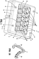
- FIGS. 1-6 illustrate an exemplary embodiment of the disclosed clip cartridge shown generally as clip cartridge 10.
- the clip cartridge 10 includes a housing 12 and a retainer 14 that is supported on the housing 12.
- the housing 12 includes a rectangular body 16 having a top surface 18 ( FIG. 2 ), side walls 20, and a central cavity 22 ( FIG. 2 ) defined by the side walls 20.
- the central cavity 22 is divided into a plurality of clip recesses 24 by dividing walls 26 that extend upwardly of the top surface 18 of the housing 12 and define transverse axes.
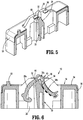
- Each of the clip recesses 24 includes a support member 30 ( FIG. 6 ) that is positioned between adjacent dividing walls 26 and has a first planar and linear clip support surface 32 ( FIG. 5 ) and a second planar and linear clip support surface 34.
- the first and second support surfaces 32, 34 are configured to support legs 38a, 38b of a clip 40 that is supported within the respective clip recess 24.
- the legs 38a, 38b are coupled together at a hinge portion 38c of the clip 40.
- the housing 12 also includes spacers 42 ( FIG. 2 ) positioned on each side of the support member 30 that define a slot 46 within the clip recess 24 in which the support member 30 is positioned.
- the housing 12 can be molded from a plastic material such as a thermoplastic material although the use of other materials including metals to form the housing 12 is envisioned.
- the top surface 18 of the housing 12 includes a plurality of protrusions 50 that extend upwardly from the top surface 18. The protrusions 50 are provided to couple the housing 12 to the retainer 14 as described in further detail below.
- the retainer 14 ( FIG. 2 ) is rectangular in shape and includes a top wall 54 and sidewalls 56 that define a cavity configured to receive an upper end 12a ( FIG. 2 ) of the housing 12.
- the top wall 54 of the retainer 14 includes openings 58 that receive the protrusions 50 to secure the retainer 14 to the top surface 18 ( FIG. 2 ) of the housing 12.
- other securement techniques can be used to secure the retainer 14 to the housing 12 of the clip cartridge 10.
- the top wall 54 of the retainer 14 defines a rectangular opening 60 that is aligned with the central cavity 22 of the housing 12 to provide access to the central cavity 22 and includes a plurality of resilient strips 62 that extend across the opening 60.
- Each of the resilient strips 62 is aligned with one of the dividing walls 26 of the housing 12 when the retainer 14 is secured to the housing 12 and includes spaced tabs 66.
- the spaced tabs 66 extend in a direction transverse to the dividing wall 26 to opposite sides of the dividing wall 26 to positions atop the legs 38a, 38b of the clips 40 received in the slots 46.
- the resilient strips 62 extend upwardly from the top wall 54 of the retainer 12 along the respective dividing walls 26 to position the tabs 66 in engagement with the legs 38a, 38b of each of the clips 40 at a location adjacent the hinge portion 38c of the clip 40.
- the tabs 66 of the retainer 14 press downwardly on the legs 38a, 38b of the clips 40 to urge the clip 40 onto the support surfaces 32, 34 of the support member 30 to retain the clips 40 within the clip cartridge 10 in an unbiased, unclamped state.
- the jaws of the clip applier are inserted into a clip recess 24 to access a clip 40.
- the tabs 66 of the retainer 14 are formed of a resilient material and will deform outwardly upon removal of a clip 40 from a recess 24 of the housing 12.
- the retainer 14 is formed of a translucent material to allow a clinician to more easily visualize a clip 40 within the housing 12 of the clip cartridge 10 during loading.
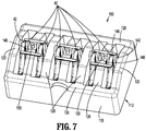
- FIGS. 7-11 illustrate another exemplary embodiment of the disclosed clip cartridge which is shown generally as clip cartridge 100.
- the clip cartridge 100 includes a housing 112 and a plurality of retainers 114 that are supported on the housing 112.
- the housing 112 includes a rectangular body 116 having longitudinal side walls 118 and transverse side walls 120 that define a central cavity 122.
- the central cavity 122 is divided into a plurality of clip recesses 124 by dividing walls 126, each of which define a transverse axis.
- the transverse side walls 120 and the dividing walls 126 extend upwardly of a top surface 128 of the longitudinal side walls 118 of the housing 112.
- Each of the clip recesses 124 includes a support member 130 that is positioned between adjacent dividing walls 126 and has a first linear clip support surface 132 ( FIG. 10 ) and a second linear clip support surface 134.
- the first and second support surfaces 132, 134 are configured to support legs 38a, 38b of clips 40 supported within the respective clip recesses 124 as described above in regard to support surfaces 32, 34 ( FIG. 6 ).
- the legs 38a, 38b of the clips 40 are coupled together at a hinge portion 38c of the clips 40.
- the support member 130 also includes spacers 142 positioned on each side of the support member 130 between the dividing walls 126 that define slots 146 within which the support members 130 are positioned.
- Each of the dividing walls 126 includes a central portion 148 located between the longitudinal side walls 118 of the housing 112.
- the central portion 148 supports a protrusion 150 that extends upwardly from the dividing wall 126.
- the protrusions 150 are provided to couple the retainers 114 to the housing 112.
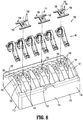
- Each of the retainers 114 has a resilient H-shaped body 154 ( FIG. 8 ) including a central body portion 156 and tabs 166 supported at each end of the central body portion 156.
- the central body portion 156 of each of the retainers 114 defines a bore 158 that receives one of the protrusions 150 extending from the central portion 148 of a respective dividing wall 126 to secure the retainer 114 to the dividing wall 126.
- the tabs 166 of the retainers 114 press downwardly on the legs 38a, 38b of the clips 40 in the clip recesses 124 on each side of the respective dividing wall 126 to urge the clip 40 onto the support surfaces 132, 134 of the support member 130 to retain the clips 40 within the clip cartridge 100 in an unbiased state.
- the jaws of the clip applier are inserted into a clip recess 124 to access a clip 40.
- the tabs 166 of the retainer 114 associated with the clip recess 124 are formed of a resilient material and will deform outwardly upon removal of the clip 40 from the recess 24 of the housing 112.
- the retainer 114 is formed of a translucent material to allow a clinician to more easily visualize a clip 40 within the housing 112 of the clip cartridge 100 during loading.
- the disclosed exemplary aspects of the disclosure of the ligation clip cartridge retain clips within the cartridge in an unbiased state to minimize damage to the clip material caused by strain on the clip. As such, the clip can be stored for longer periods of time.
Landscapes
- Health & Medical Sciences (AREA)
- Surgery (AREA)
- Life Sciences & Earth Sciences (AREA)
- Heart & Thoracic Surgery (AREA)
- Nuclear Medicine, Radiotherapy & Molecular Imaging (AREA)
- Engineering & Computer Science (AREA)
- Biomedical Technology (AREA)
- Medical Informatics (AREA)
- Molecular Biology (AREA)
- Animal Behavior & Ethology (AREA)
- General Health & Medical Sciences (AREA)
- Public Health (AREA)
- Veterinary Medicine (AREA)
- Vascular Medicine (AREA)
- Reproductive Health (AREA)
- Surgical Instruments (AREA)
Abstract
Description
- This disclosure is directed to a clip cartridge and, more particularly, to a clip cartridge for polymeric ligation clips.
- Clip cartridges for supporting polymeric clips are known and typically include a base portion and a retaining member or retaining members. The base portion defines a number of slots that include supporting elements for supporting individual clips within the slots. The retaining member(s) is secured to the base portion and is configured engage a clip or clips to retain the clip or clips within the respective slots of the base portion on the supporting elements. A clip applier is inserted into the slots to remove a clip from the slot and to load a clip onto the clip applier.
- In known clip cartridges, the retaining member(s) applies a load on the clip or clips to retain the clip or clips within the respective slots of the clip cartridge in a compressed or preloaded state. The retaining member may also obstruct visualization of the clip within the slot of the staple cartridge which may make loading of a clip into a clip applier difficult.
- One aspect of the disclosure is directed to a clip cartridge including a housing, at least one retainer, and a plurality of clips. The housing includes a body having side walls defining a central cavity and a plurality of dividing walls extending across the central cavity. Each of the plurality of dividing walls defines a transverse axis and forms a clip recess within the central cavity with an adjacent one of the plurality of dividing walls. A support member is positioned within each of the clip recesses and includes a first support surface and a second support surface. The plurality of clips is supported within the central cavity of the housing, with one clip being supported within each of the clip recesses. Each clip has first and second legs that are interconnected by a hinge portion. The least one retainer is supported on the housing and has tabs that extend in a direction transverse to the transverse axis defined by the dividing walls. The tabs are positioned to engage the first and second legs of the clips to urge the first leg onto the first support surface of a respective support member and to urge the second leg onto the second support surface of a respective support member.
- Another aspect of the disclosure is directed to a clip cartridge including a housing and a retainer. The housing includes a body having side walls defining a central cavity and a plurality of dividing walls extending across the central cavity. Each of the plurality of dividing walls defines a transverse axis and forms a clip recess within the central cavity with an adjacent one of the plurality of dividing walls. A support member is positioned within each of the clip recesses and includes a first support surface and a second support surface. A clip is supported within each of the clip recesses of the housing. Each of the clips has a first leg, a second leg, and a hinge portion interconnecting the first and second legs. The retainer is supported on the housing and has tabs that extend in a direction transverse to the transverse axis defined by the dividing walls. The tabs are positioned to engage the first and second legs of the clips to urge the first leg onto the first support surface of a respective support member and to urge the second leg onto the second support surface of a respective support member.
- Another aspect of the disclosure is directed to a clip cartridge including a housing and a plurality of retainers. The housing includes a body having side walls defining a central cavity and a plurality of dividing walls extending across the central cavity. Each of the plurality of dividing walls defines a transverse axis and forms a clip recess within the central cavity with an adjacent dividing wall. A support member is positioned within each of the clip recesses and includes a first support surface and a second support surface. A clip is supported within each of the clip recesses on the support member. Each of the clips has a first leg, a second leg, and a hinge portion interconnecting the first and the second legs. The plurality of retainers is supported on the housing. Each of the plurality of retainers is supported on one of the plurality of dividing walls and includes tabs that extend in a direction transverse to the transverse axes defined by the plurality of dividing walls. The tabs are positioned to engage the first and second legs of the clips in the clip recesses located adjacent to the dividing wall to urge the first legs of the respective clips onto the first support surfaces of the respective support members and to urge the second legs of the respective clips onto the second support surfaces of the respective support members.
- In aspects of the disclosure, each of the first and second support surfaces of the support member is linear.
- In some aspects of the disclosure, each of the support members includes spacers that are positioned between the dividing walls and define slots that are configured to receive a clip of the plurality of clips, wherein the first and second support surfaces are positioned within the slot.
- In certain aspects of the disclosure, the retainer includes side walls and a top wall that define a cavity that is configured to receive an upper end of the housing.
- In aspects of the disclosure, the top wall of the retainer includes openings and the housing includes a top surface having protrusions, wherein the protrusions are received within the openings to secure the retainer to the housing.
- In some aspects of the disclosure, the retainer includes a body that defines an opening that is aligned with the central cavity of the housing and the body includes a plurality of resilient strips that extend across the opening, wherein each of the resilient strips supports the tabs and is aligned with a respective one of the plurality of dividing walls.
- In certain aspects of the disclosure, the bodies of the housing and of the retainer are rectangular.
- In aspects of the disclosure, each of the retainers includes an H-shaped body having a central portion, and the tabs are supported on each end of the central portion.
- In some aspects of the disclosure, the central portion of each of the retainers is supported on a respective one of the plurality of dividing walls such that the tabs of each of the retainers extend above the clip recesses adjacent to the respective dividing wall.
- In certain aspects of the disclosure, the central portion of each of the at least one retainer defines an opening and each of the at least one dividing wall includes a protrusion, wherein the opening receives the protrusion to secure the at least one retainer to the respective dividing wall of the housing.
- In aspects of the disclosure, the at least one retainer is formed of a translucent material.
- In aspects of the disclosure, the retainer includes a body that defines an opening that is aligned with the central cavity of the housing and the body includes a plurality of resilient strips that extend across the opening, wherein each of the resilient strips supports the tabs and is aligned with a respective one of the plurality of dividing walls.
- Other features of the disclosure will be appreciated from the following description.
- Various aspects of the disclosed ligation clip cartridge are described herein below with reference to the drawings, wherein:
-
FIG. 1 is a perspective first side view from above of an exemplary embodiment of the disclosed ligation clip cartridge; -
FIG. 1A is a side perspective view of an exemplary embodiment of a ligation clip of the ligation clip cartridge shown inFIG. 1 ; -
FIG. 2 is an exploded perspective view of the ligation clip cartridge shown inFIG. 4 ; -
FIG. 3 is a perspective second side view from above of the disclosed ligation clip cartridge shown inFIG. 1 ; -
FIG. 4 is a top view of the clip cartridge shown inFIG. 3 ; -
FIG. 5 is a cross-sectional view taken along section line 5-5 ofFIG. 4 ; -
FIG. 6 is a cross-sectional view taken along section line 6-6 ofFIG. 4 ; -
FIG. 7 is a perspective first side view from above of another exemplary embodiment of the disclosed ligation clip cartridge; -
FIG. 8 is an exploded perspective view of the ligation clip cartridge shown inFIG. 9 ; -
FIG. 9 is a top view of the ligation clip cartridge shown inFIG. 8 ; -
FIG. 10 is a cross-sectional view taken along section line 10-10 ofFIG. 9 ; and -
FIG. 11 is a cross-sectional view taken along section line 11-11FIG. 9 . - The disclosed ligation clip cartridge will now be described in detail with reference to the drawings in which like reference numerals designate identical or corresponding elements in each of the several views. However, it is to be understood that the disclosed aspects are merely exemplary of the disclosure and may be embodied in various forms. Well-known functions or constructions are not described in detail to avoid obscuring the disclosure in unnecessary detail. Therefore, specific structural and functional details disclosed herein are not to be interpreted as limiting, but merely as a basis for the claims and as a representative basis for teaching one skilled in the art to variously employ the disclosure in virtually any appropriately detailed structure. In addition, directional terms such as front, rear, upper, lower, top, bottom, distal, proximal, and similar terms are used to assist in understanding the description and are not intended to limit the disclosure.
- In this description, the term "clinician" is used generally to refer to medical personnel including doctors, nurses, and support personnel.
-
FIGS. 1-6 illustrate an exemplary embodiment of the disclosed clip cartridge shown generally asclip cartridge 10. Theclip cartridge 10 includes ahousing 12 and aretainer 14 that is supported on thehousing 12. Thehousing 12 includes arectangular body 16 having a top surface 18 (FIG. 2 ),side walls 20, and a central cavity 22 (FIG. 2 ) defined by theside walls 20. The central cavity 22 is divided into a plurality of clip recesses 24 by dividingwalls 26 that extend upwardly of thetop surface 18 of thehousing 12 and define transverse axes. Each of the clip recesses 24 includes a support member 30 (FIG. 6 ) that is positioned between adjacent dividingwalls 26 and has a first planar and linear clip support surface 32 (FIG. 5 ) and a second planar and linearclip support surface 34. The first and second support surfaces 32, 34, respectively, are configured to supportlegs clip 40 that is supported within therespective clip recess 24. Thelegs hinge portion 38c of theclip 40. Thehousing 12 also includes spacers 42 (FIG. 2 ) positioned on each side of thesupport member 30 that define aslot 46 within theclip recess 24 in which thesupport member 30 is positioned. - The
housing 12 can be molded from a plastic material such as a thermoplastic material although the use of other materials including metals to form thehousing 12 is envisioned. In aspects of the disclosure, thetop surface 18 of thehousing 12 includes a plurality ofprotrusions 50 that extend upwardly from thetop surface 18. Theprotrusions 50 are provided to couple thehousing 12 to theretainer 14 as described in further detail below. - The retainer 14 (
FIG. 2 ) is rectangular in shape and includes atop wall 54 andsidewalls 56 that define a cavity configured to receive an upper end 12a (FIG. 2 ) of thehousing 12. Thetop wall 54 of theretainer 14 includesopenings 58 that receive theprotrusions 50 to secure theretainer 14 to the top surface 18 (FIG. 2 ) of thehousing 12. Alternately, other securement techniques can be used to secure theretainer 14 to thehousing 12 of theclip cartridge 10. - The
top wall 54 of theretainer 14 defines arectangular opening 60 that is aligned with the central cavity 22 of thehousing 12 to provide access to the central cavity 22 and includes a plurality ofresilient strips 62 that extend across theopening 60. Each of theresilient strips 62 is aligned with one of the dividingwalls 26 of thehousing 12 when theretainer 14 is secured to thehousing 12 and includes spacedtabs 66. The spacedtabs 66 extend in a direction transverse to the dividingwall 26 to opposite sides of the dividingwall 26 to positions atop thelegs clips 40 received in theslots 46. - In aspects of the disclosure, the
resilient strips 62 extend upwardly from thetop wall 54 of theretainer 12 along therespective dividing walls 26 to position thetabs 66 in engagement with thelegs clips 40 at a location adjacent thehinge portion 38c of theclip 40. When theretainer 14 is attached to thehousing 12, thetabs 66 of theretainer 14 press downwardly on thelegs clips 40 to urge theclip 40 onto the support surfaces 32, 34 of thesupport member 30 to retain theclips 40 within theclip cartridge 10 in an unbiased, unclamped state. - During loading of a
clip 40 between the jaws of a clip applier (not shown), the jaws of the clip applier are inserted into aclip recess 24 to access aclip 40. Thetabs 66 of theretainer 14 are formed of a resilient material and will deform outwardly upon removal of aclip 40 from arecess 24 of thehousing 12. In aspects of the disclosure, theretainer 14 is formed of a translucent material to allow a clinician to more easily visualize aclip 40 within thehousing 12 of theclip cartridge 10 during loading. -
FIGS. 7-11 illustrate another exemplary embodiment of the disclosed clip cartridge which is shown generally asclip cartridge 100. Theclip cartridge 100 includes ahousing 112 and a plurality ofretainers 114 that are supported on thehousing 112. Thehousing 112 includes arectangular body 116 havinglongitudinal side walls 118 andtransverse side walls 120 that define acentral cavity 122. Thecentral cavity 122 is divided into a plurality of clip recesses 124 by dividingwalls 126, each of which define a transverse axis. Thetransverse side walls 120 and the dividingwalls 126 extend upwardly of atop surface 128 of thelongitudinal side walls 118 of thehousing 112. Each of the clip recesses 124 includes asupport member 130 that is positioned between adjacent dividingwalls 126 and has a first linear clip support surface 132 (FIG. 10 ) and a second linearclip support surface 134. The first and second support surfaces 132, 134, respectively, are configured to supportlegs clips 40 supported within the respective clip recesses 124 as described above in regard to supportsurfaces 32, 34 (FIG. 6 ). As described above, thelegs clips 40 are coupled together at ahinge portion 38c of theclips 40. Thesupport member 130 also includesspacers 142 positioned on each side of thesupport member 130 between the dividingwalls 126 that defineslots 146 within which thesupport members 130 are positioned. - Each of the dividing
walls 126 includes acentral portion 148 located between thelongitudinal side walls 118 of thehousing 112. Thecentral portion 148 supports aprotrusion 150 that extends upwardly from the dividingwall 126. Theprotrusions 150 are provided to couple theretainers 114 to thehousing 112. - Each of the
retainers 114 has a resilient H-shaped body 154 (FIG. 8 ) including acentral body portion 156 andtabs 166 supported at each end of thecentral body portion 156. Thecentral body portion 156 of each of theretainers 114 defines abore 158 that receives one of theprotrusions 150 extending from thecentral portion 148 of arespective dividing wall 126 to secure theretainer 114 to the dividingwall 126. When theretainers 114 are attached to the dividingwalls 126 of thehousing 112 of theclip cartridge 100, thetabs 166 of theretainers 114 press downwardly on thelegs clips 40 in the clip recesses 124 on each side of therespective dividing wall 126 to urge theclip 40 onto the support surfaces 132, 134 of thesupport member 130 to retain theclips 40 within theclip cartridge 100 in an unbiased state. - During loading of a
clip 40 between the jaws of a clip applier (not shown), the jaws of the clip applier are inserted into aclip recess 124 to access aclip 40. Thetabs 166 of theretainer 114 associated with theclip recess 124 are formed of a resilient material and will deform outwardly upon removal of theclip 40 from therecess 24 of thehousing 112. In aspects of the disclosure, theretainer 114 is formed of a translucent material to allow a clinician to more easily visualize aclip 40 within thehousing 112 of theclip cartridge 100 during loading. - The disclosed exemplary aspects of the disclosure of the ligation clip cartridge retain clips within the cartridge in an unbiased state to minimize damage to the clip material caused by strain on the clip. As such, the clip can be stored for longer periods of time.
- Persons skilled in the art will understand that the devices and methods specifically described herein and illustrated in the accompanying drawings are non-limiting exemplary aspects of the disclosure. It is envisioned that the elements and features illustrated or described in connection with one exemplary embodiment may be combined with the elements and features of another without departing from the scope of the disclosure. As well, one skilled in the art will appreciate further features and advantages of the disclosure based on the above-described aspects of the disclosure. Accordingly, the disclosure is not to be limited by what has been particularly shown and described, except as indicated by the appended claims.
- The invention is described by the following numbered paragraphs: -
- 1. A clip cartridge comprising;
a housing including a body having side walls defining a central cavity and a plurality of dividing walls extending across the central cavity, each of the plurality of dividing walls defining a transverse axis and forming a clip recess within the central cavity with an adjacent one of the plurality of dividing walls, and a support member positioned within each of the clip recesses, the support member including a first support surface and a second support surface;
a plurality of clips supported within the central cavity of the housing, one of the plurality of clips being supported within each of the clip recesses on the support member, each of the plurality of clips having a first and a second leg that are interconnected by a hinge portion; and
at least one retainer supported on the housing, the at least one retainer having tabs that extend in a direction transverse to the transverse axis defined by the dividing walls, the tabs being positioned to engage the first and second legs of the plurality of clips to urge the first leg onto the first support surface of a respective support member and to urge the second leg onto the second support surface of a respective support member. - 2. The clip cartridge of paragraph 1, wherein each of the first and second support surfaces of the support member is linear.
- 3. The clip cartridge of paragraph 1, wherein each of the support members includes spacers positioned between the dividing walls, the spacers defining a slot configured to receive a clip of the plurality of clips, the first and second support surfaces positioned within the slot.
- 4. The clip cartridge of paragraph 1, wherein the at least one retainer includes side walls and a top wall, the side walls and the top wall defining a cavity configured to receive an upper end of the housing.
- 5. The clip cartridge of paragraph 4, wherein the top wall of the at least one retainer includes openings and the housing includes a top surface having protrusions, the protrusions received within the openings to secure the at least one retainer to the housing.
- 6. The clip cartridge of paragraph 1, wherein the at least one retainer includes a body that defines an opening that is aligned with the central cavity of the housing, the body including a plurality of resilient strips that extend across the opening, each of the resilient strips supporting the tabs and being aligned with a respective one of the plurality of dividing walls.
- 7. The clip cartridge of paragraph 1, wherein the bodies of the housing and of the one retainer are rectangular.
- 8. The clip cartridge of paragraph 1, wherein each of the at least one retainer includes an H-shaped body having a central portion, and the tabs are supported on each end of the central portion.
- 9. The clip cartridge of paragraph 8, wherein the central portion of each of the at least one retainer is supported on a respective one of the plurality of dividing walls such that the tabs of each of the at least one retainer extend above the clip recesses adjacent to the respective dividing wall.
- 10. The clip cartridge of paragraph 9, wherein the central portion of each of the at least one retainer defines an opening and each of the at least one dividing walls includes a protrusion, the opening receiving the protrusion to secure the at least one retainer to the respective dividing wall of the housing.
- 11. The clip cartridge of paragraph 1, wherein the at least one retainer is formed of a translucent material.
- 12. A clip cartridge comprising:
- a housing including a body having side walls defining a central cavity and a plurality of dividing walls extending across the central cavity, each of the plurality of dividing walls defining a transverse axis and forming a clip recess within the central cavity with an adjacent one of the plurality of dividing walls, and a support member positioned within each of the clip recesses, the support member including a first support surface and a second support surface;
- a clip supported within each of the clip recesses on the support member, each of the clips having a first leg, a second leg, and a hinge portion interconnecting the first leg and the second leg; and
- a plurality of retainers supported on the housing, each of the plurality of retainers supported on one of the plurality of dividing walls and including tabs that extend in a direction transverse to the transverse axis defined by the plurality of dividing walls, the tabs being positioned to engage the first and second legs of the clips in the clip recesses located adjacent to the dividing wall to urge the first legs of the respective clips onto the first support surfaces of the respective support members and to urge the second legs of the respective clips onto the second support surfaces of the respective support members.
- 13. The clip cartridge of
paragraph 12, wherein each of the plurality of retainers includes an H-shaped body having a central portion, the tabs supported on each end of the central portion. - 14. The clip cartridge of paragraph 13, wherein the central portion of each of the plurality of retainers defines an opening and each of the plurality of dividing walls includes a protrusion, the opening receiving the protrusion to secure the plurality of retainers to the respective dividing walls of the housing.
- 15. The clip cartridge of
paragraph 12, wherein the at least one retainer is formed of a translucent material. - 16. A clip cartridge comprising;
- a housing including a body having side walls defining a central cavity and a plurality of dividing walls extending across the central cavity, each of the plurality of dividing walls defining a transverse axis and forming a clip recess within the central cavity with an adjacent one of the plurality of dividing walls, and a support member positioned within each of the clip recesses, the support member including a first support surface and a second support surface;
- a clip supported within each of the clip recesses of the housing on the support member, each of the clips having a first leg, a second leg, and a hinge portion interconnecting the first and second legs; and
- a retainer supported on the housing, the retainer having tabs that extend in a direction transverse to the transverse axis defined by the dividing walls, the tabs being positioned to engage the first and second legs of the clips the first leg onto the first support surface and to urge the second leg onto the second support surface of a respective support member.
- 17. The clip cartridge of
paragraph 16, wherein the retainer includes a body that defines an opening that is aligned with the central cavity of the housing, the body including a plurality of resilient strips that extend across the opening, each of the resilient strips supporting the tabs and being aligned with a respective one of the plurality of dividing walls. - 18. The clip cartridge of
paragraph 16, wherein the retainer includes side walls and a top wall, the side walls and the top wall defining a cavity configured to receive an upper end of the housing. - 19. The clip cartridge of
paragraph 16, wherein the retainer is formed of a translucent material. - 20. The clip cartridge of
paragraph 16, wherein the retainer includes side walls and a top wall that define a cavity that receives an upper end of the housing, the top wall of the retainer defining openings and the housing including a top surface having protrusions, the protrusions received within the openings to secure the retainer to the housing.
Claims (15)
- A clip cartridge comprising;
a housing including a body having side walls defining a central cavity and a plurality of dividing walls extending across the central cavity, each of the plurality of dividing walls defining a transverse axis and forming a clip recess within the central cavity with an adjacent one of the plurality of dividing walls, and a support member positioned within each of the clip recesses, the support member including a first support surface and a second support surface;
a plurality of clips supported within the central cavity of the housing, one of the plurality of clips being supported within each of the clip recesses on the support member, each of the plurality of clips having a first and a second leg that are interconnected by a hinge portion; and
at least one retainer supported on the housing, the at least one retainer having tabs that extend in a direction transverse to the transverse axis defined by the dividing walls, the tabs being positioned to engage the first and second legs of the plurality of clips to urge the first leg onto the first support surface of a respective support member and to urge the second leg onto the second support surface of a respective support member. - The clip cartridge of claim 1, wherein each of the first and second support surfaces of the support member is linear.
- The clip cartridge of claim 1 or claim 2, wherein each of the support members includes spacers positioned between the dividing walls, the spacers defining a slot configured to receive a clip of the plurality of clips, the first and second support surfaces positioned within the slot.
- The clip cartridge of any preceding claim, wherein the at least one retainer includes side walls and a top wall, the side walls and the top wall defining a cavity configured to receive an upper end of the housing; preferably wherein the top wall of the at least one retainer includes openings and the housing includes a top surface having protrusions, the protrusions received within the openings to secure the at least one retainer to the housing.
- The clip cartridge of any preceding claim, wherein the at least one retainer includes a body that defines an opening that is aligned with the central cavity of the housing, the body including a plurality of resilient strips that extend across the opening, each of the resilient strips supporting the tabs and being aligned with a respective one of the plurality of dividing walls.
- The clip cartridge of any preceding claim, wherein the bodies of the housing and of the one retainer are rectangular; and/or wherein each of the at least one retainer includes an H-shaped body having a central portion, and the tabs are supported on each end of the central portion ;preferably wherein the central portion of each of the at least one retainer is supported on a respective one of the plurality of dividing walls such that the tabs of each of the at least one retainer extend above the clip recesses adjacent to the respective dividing wall; preferably still wherein the central portion of each of the at least one retainer defines an opening and each of the at least one dividing walls includes a protrusion, the opening receiving the protrusion to secure the at least one retainer to the respective dividing wall of the housing.
- The clip cartridge of any preceding claim, wherein the at least one retainer is formed of a translucent material.
- A clip cartridge comprising:a housing including a body having side walls defining a central cavity and a plurality of dividing walls extending across the central cavity, each of the plurality of dividing walls defining a transverse axis and forming a clip recess within the central cavity with an adjacent one of the plurality of dividing walls, and a support member positioned within each of the clip recesses, the support member including a first support surface and a second support surface;a clip supported within each of the clip recesses on the support member, each of the clips having a first leg, a second leg, and a hinge portion interconnecting the first leg and the second leg; anda plurality of retainers supported on the housing, each of the plurality of retainers supported on one of the plurality of dividing walls and including tabs that extend in a direction transverse to the transverse axis defined by the plurality of dividing walls, the tabs being positioned to engage the first and second legs of the clips in the clip recesses located adjacent to the dividing wall to urge the first legs of the respective clips onto the first support surfaces of the respective support members and to urge the second legs of the respective clips onto the second support surfaces of the respective support members.
- The clip cartridge of claim 8, wherein each of the plurality of retainers includes an H-shaped body having a central portion, the tabs supported on each end of the central portion.
- The clip cartridge of claim 8 or claim 9, wherein the central portion of each of the plurality of retainers defines an opening and each of the plurality of dividing walls includes a protrusion, the opening receiving the protrusion to secure the plurality of retainers to the respective dividing walls of the housing.
- The clip cartridge of any of claims 8 to 10, wherein the at least one retainer is formed of a translucent material.
- A clip cartridge comprising;
a housing including a body having side walls defining a central cavity and a plurality of dividing walls extending across the central cavity, each of the plurality of dividing walls defining a transverse axis and forming a clip recess within the central cavity with an adjacent one of the plurality of dividing walls, and a support member positioned within each of the clip recesses, the support member including a first support surface and a second support surface;
a clip supported within each of the clip recesses of the housing on the support member, each of the clips having a first leg, a second leg, and a hinge portion interconnecting the first and second legs; and
a retainer supported on the housing, the retainer having tabs that extend in a direction transverse to the transverse axis defined by the dividing walls, the tabs being positioned to engage the first and second legs of the clips the first leg onto the first support surface and to urge the second leg onto the second support surface of a respective support member. - The clip cartridge of claim 12, wherein the retainer includes a body that defines an opening that is aligned with the central cavity of the housing, the body including a plurality of resilient strips that extend across the opening, each of the resilient strips supporting the tabs and being aligned with a respective one of the plurality of dividing walls.
- The clip cartridge of claim 12 or claim 13, wherein the retainer includes side walls and a top wall, the side walls and the top wall defining a cavity configured to receive an upper end of the housing; and/or wherein the retainer is formed of a translucent material.
- The clip cartridge of any of claims 12 to 14, wherein the retainer includes side walls and a top wall that define a cavity that receives an upper end of the housing, the top wall of the retainer defining openings and the housing including a top surface having protrusions, the protrusions received within the openings to secure the retainer to the housing.
Applications Claiming Priority (2)
| Application Number | Priority Date | Filing Date | Title |
|---|---|---|---|
| US201962844911P | 2019-05-08 | 2019-05-08 | |
| US16/830,417 US11471165B2 (en) | 2019-05-08 | 2020-03-26 | Ligation clip cartridge |
Publications (2)
| Publication Number | Publication Date |
|---|---|
| EP3735915A1 true EP3735915A1 (en) | 2020-11-11 |
| EP3735915B1 EP3735915B1 (en) | 2025-04-16 |
Family
ID=70553924
Family Applications (1)
| Application Number | Title | Priority Date | Filing Date |
|---|---|---|---|
| EP20173032.2A Active EP3735915B1 (en) | 2019-05-08 | 2020-05-05 | Ligation clip cartridge |
Country Status (3)
| Country | Link |
|---|---|
| US (1) | US11471165B2 (en) |
| EP (1) | EP3735915B1 (en) |
| CN (1) | CN111904485A (en) |
Citations (4)
| Publication number | Priority date | Publication date | Assignee | Title |
|---|---|---|---|---|
| US4936447A (en) * | 1989-09-26 | 1990-06-26 | Horizon Surgical Inc. | Hemostatic clip holder |
| US20040040875A1 (en) * | 2002-08-27 | 2004-03-04 | Gallagher Richard J. | Cartridge for holding asymmetric surgical clips and method for loading surgical clips into a clip applier |
| US20060124485A1 (en) * | 2004-12-10 | 2006-06-15 | Kennedy Daniel L | Enhanced visibility cartridge with improved retainer |
| US20190008521A1 (en) * | 2017-07-07 | 2019-01-10 | Wieslaw Mieczyslaw Brodaczewski | Retainer for polymeric ligating clip cartridge |
Family Cites Families (115)
| Publication number | Priority date | Publication date | Assignee | Title |
|---|---|---|---|---|
| US3439523A (en) | 1964-03-30 | 1969-04-22 | Peter B Samuels | Hemostatic clip constructions |
| BE654195A (en) | 1964-10-09 | 1965-02-01 | ||
| US3713533A (en) | 1971-04-28 | 1973-01-30 | Codman & Shurtleff | Hemostatic clip holder |
| US4076120A (en) | 1976-12-10 | 1978-02-28 | American Hospital Supply Corporation | Cartridge for holding hemostatic clips |
| US4187712A (en) | 1977-04-08 | 1980-02-12 | Samuels Peter B | Hemostatic clip applicator |
| US4146130A (en) | 1977-04-08 | 1979-03-27 | Samuels Peter B | Hemostatic clip, clip applicator and cartridge therefor |
| US4212390A (en) | 1977-10-20 | 1980-07-15 | Propper Manufacturing Co., Inc. | Wound clip rack |
| US4212303A (en) | 1978-07-17 | 1980-07-15 | Hollister Incorporated | Umbilical cord clamp |
| US4390019A (en) | 1979-02-28 | 1983-06-28 | Leveen Harry H | Blood vessel clamp |
| US4418694A (en) | 1979-06-18 | 1983-12-06 | Ethicon, Inc. | Non-metallic, bio-compatible hemostatic clips |
| US4294355A (en) | 1979-12-06 | 1981-10-13 | Ethicon, Inc. | Cartridge for hemostatic clips |
| US4344531A (en) | 1980-09-08 | 1982-08-17 | Edward Weck & Company, Inc. | Hemostatic clip cartridge |
| US4346869A (en) | 1981-03-12 | 1982-08-31 | Macneill Robert L | Tube clamp |
| US4412617A (en) | 1981-07-20 | 1983-11-01 | Ethicon, Inc. | Ligating clip package |
| US4361229A (en) | 1981-08-03 | 1982-11-30 | Ethicon, Inc. | Cartridge for hemostatic clips |
| US4449531A (en) | 1981-08-27 | 1984-05-22 | Ethicon, Inc. | Non-metallic, bio-compatible hemostatic clips with interlocking latch means |
| US4550729A (en) | 1981-08-27 | 1985-11-05 | Ethicon, Inc. | Non-metallic, bio-compatible hemostatic clips with interlocking latch means |
| US4485953A (en) | 1982-04-05 | 1984-12-04 | Senco Products, Inc. | Surgical stapling instrument and cartridge therefor |
| US4487205A (en) | 1982-04-26 | 1984-12-11 | Ethicon, Inc. | Non-metallic, bio-compatible hemostatic clips |
| US4696396A (en) | 1985-12-19 | 1987-09-29 | Samuels Peter B | Hemostatic clip cartridge |
| US4726372A (en) | 1986-09-19 | 1988-02-23 | Metatech Corporation | Hemostatic clip |
| US4834096A (en) | 1987-10-26 | 1989-05-30 | Edward Weck Incorporated | Plastic ligating clips |
| US4971198A (en) | 1988-04-18 | 1990-11-20 | Edward Weck Incorporated | Hemostatic clip and cartridge assembly |
| US4942886A (en) | 1989-02-22 | 1990-07-24 | Timmons John W | External incontinency device |
| US5062846A (en) | 1989-03-28 | 1991-11-05 | Edward Weck Incorporated | Penetrating plastic ligating clip |
| US4972949A (en) | 1989-09-26 | 1990-11-27 | Horizon Surgical, Inc. | Hemostatic clip holder for small clips |
| US5100416A (en) | 1989-10-17 | 1992-03-31 | Edward Weck Incorporated | Ligating clip applying instrument |
| US4961499A (en) | 1990-01-04 | 1990-10-09 | Pilling Co. | Hemostatic clip cartridge |
| US5046624A (en) | 1990-08-13 | 1991-09-10 | Murphy Susan A | Surgical instrument stand |
| US5050272A (en) | 1990-10-16 | 1991-09-24 | Anago, Inc. | Closure member for an ice bag |
| US5201416A (en) | 1990-10-22 | 1993-04-13 | Edward Weck Incorporated | Hemostatic clip cartridge |
| US5046611A (en) | 1990-10-22 | 1991-09-10 | Edward Weck Incorporated | Hemostatic clip cartridge |
| US5423831A (en) | 1991-01-24 | 1995-06-13 | Nates; Colin | Clamp |
| US5279416A (en) | 1992-06-05 | 1994-01-18 | Edward Weck Incorporated | Ligating device cartridge with separable retainer |
| US5403327A (en) | 1992-12-31 | 1995-04-04 | Pilling Weck Incorporated | Surgical clip applier |
| US5697942A (en) | 1994-07-31 | 1997-12-16 | Palti; Yoram | Internal vascular clamp |
| US5908430A (en) | 1995-06-07 | 1999-06-01 | Appleby; Timothy | Easy loading hemostatic clip and cartridge |
| US5564262A (en) | 1995-07-20 | 1996-10-15 | Ethicon, Inc. | Ligaclip loading machine and process |
| US5713912A (en) | 1995-08-30 | 1998-02-03 | Stress Management, Inc. | Ligating clip having ramp-shaped vessel clamping members and tool for applying same |
| US5676676A (en) | 1995-08-30 | 1997-10-14 | Porter; Wayne | Ligating clip having ramp-shaped vessel-clamping members |
| US5846255A (en) | 1996-01-31 | 1998-12-08 | Casey Medical Products Limited | Surgical clip |
| FR2751863B1 (en) | 1996-08-01 | 1999-01-22 | Vitalitec International | HEMOSTATIC CLIPS SUPPORT |
| GB9707204D0 (en) | 1997-04-09 | 1997-05-28 | Price Invena Aps | Clamping and cutting devices |
| US6044971A (en) | 1997-10-10 | 2000-04-04 | United States Surgical Corporation | Clip cartridge |
| US5921991A (en) | 1997-10-23 | 1999-07-13 | Biomax Technologies Inc. | Multi-colored umbilical cord clamp |
| JP2000131620A (en) | 1998-10-27 | 2000-05-12 | Olympus Optical Co Ltd | telescope |
| US6217590B1 (en) | 1999-01-22 | 2001-04-17 | Scion International, Inc. | Surgical instrument for applying multiple staples and cutting blood vessels and organic structures and method therefor |
| US6228097B1 (en) | 1999-01-22 | 2001-05-08 | Scion International, Inc. | Surgical instrument for clipping and cutting blood vessels and organic structures |
| DE19903752C1 (en) | 1999-01-30 | 2000-03-30 | Aesculap Ag & Co Kg | Clip magazine for haemostatic medical clip driver has independent actuated clamps for arms and bases of clips |
| GB2353710A (en) | 1999-08-06 | 2001-03-07 | Henleys Medical Supplies Ltd | Umbilical cord clamp |
| IL132913A (en) | 1999-11-14 | 2004-09-27 | Porat Michael | Device and method for clamping and cutting a flexible deformable tube |
| US6419682B1 (en) | 2000-03-24 | 2002-07-16 | Timothy Appleby | Hemostatic clip cartridge |
| US6391035B1 (en) | 2000-03-24 | 2002-05-21 | Timothy Appleby | Hemostatic clip removal instrument |
| US6349727B1 (en) | 2000-05-25 | 2002-02-26 | Pos-T-Vac, Inc. | Penile clamp for inhibiting incontinence |
| US6273253B1 (en) | 2000-07-07 | 2001-08-14 | Vitalitec International, Inc. | Cartridge and system for holding and applying clips |
| US20020046961A1 (en) | 2000-10-19 | 2002-04-25 | Scion International | Surgical clip holder and method therefor |
| DE10116168A1 (en) | 2001-03-31 | 2001-11-29 | Joachim Heinzl | Clip has gripper arms operated by articulated lever mechanism and joined by spacer piece, tie rod, pulley cable, locking mechanism with cogging and pawl |
| US20020177863A1 (en) | 2001-05-24 | 2002-11-28 | Mandel Stanley R. | Surface treated ligating clip |
| US6824547B2 (en) | 2001-07-13 | 2004-11-30 | Pilling Weck Incorporated | Endoscopic clip applier and method |
| US20030069589A1 (en) | 2001-10-09 | 2003-04-10 | Small George H. | Umbilical cord clamp and methods of using same |
| US20040199178A1 (en) | 2001-10-09 | 2004-10-07 | Small George H. | Umbilical cord clamp and methods of using same |
| US7131977B2 (en) | 2002-08-27 | 2006-11-07 | Pilling Weck Incorporated | Apparatus and method for removing a clip |
| US7211091B2 (en) | 2002-08-27 | 2007-05-01 | Pilling Weck Incorporated | Fingertip-actuated surgical clip applier and related methods |
| US6863675B2 (en) | 2002-09-20 | 2005-03-08 | Pilling Weck Incorporated | Ligating clip with integral penetrating hook |
| US7052504B2 (en) | 2002-11-19 | 2006-05-30 | Teleflex Incorporated | Automated-feed surgical clip applier and related methods |
| US7211092B2 (en) | 2002-11-19 | 2007-05-01 | Pilling Weck Incorporated | Automated-feed surgical clip applier and related methods |
| WO2004080290A2 (en) | 2003-03-11 | 2004-09-23 | Tyco Healthcare Group, Lp | Clip applying apparatus with angled jaw |
| US7144402B2 (en) | 2003-06-16 | 2006-12-05 | Synovis Life Technologies, Inc. | Vascular clamp |
| US7316696B2 (en) | 2004-01-22 | 2008-01-08 | Teleflex Medical Incorporated | Ligating clip with integral interlocking latch mechanism |
| US7326223B2 (en) | 2004-01-22 | 2008-02-05 | Teleflex Medical Incorporated | Ligating clip with integral cutting guide |
| US20050165423A1 (en) | 2004-01-23 | 2005-07-28 | Pilling Weck Incorporated | Ligating clip with integral tissue-securing mechanism |
| US7001412B2 (en) | 2004-01-28 | 2006-02-21 | Pilling Weck Incorporated | Surgical clip with integral suture-securing mechanism |
| US7585304B2 (en) | 2004-02-02 | 2009-09-08 | Teleflex Medical Incorporated | Endoscopic clip applying apparatus with improved aperture for clip release and related method |
| US7857129B2 (en) | 2004-03-07 | 2010-12-28 | Synthes Usa, Llc | Container and carrier system for surgical auxiliary material |
| US7452368B2 (en) | 2004-09-15 | 2008-11-18 | Ethicon, Inc. | System for holding surgical fasteners |
| US20060217749A1 (en) | 2005-03-24 | 2006-09-28 | Pilling Weck Incorporated | Reduced closure force ligating clip |
| DE102005045006B3 (en) | 2005-09-21 | 2007-01-04 | Cardiomedical Gmbh | Case for haemostatic clamps for surgical use has bottom part containing pockets and bracket to hold clamp and top part with clamp parts to hold clamp securely in each clamp pocket |
| US20070083218A1 (en) | 2005-10-12 | 2007-04-12 | A Morris Steven | Coated ligating clip |
| US20070118161A1 (en) | 2005-11-22 | 2007-05-24 | Kennedy Daniel L | Non-snag polymer ligating clip |
| US9486225B2 (en) | 2005-12-22 | 2016-11-08 | Robert E. Michler | Exclusion of the left atrial appendage |
| US9480480B2 (en) | 2005-12-22 | 2016-11-01 | Albert N. Santilli | Vascular and intestinal occlusion |
| US8328458B2 (en) | 2007-07-20 | 2012-12-11 | Twin Bay Medical, Inc. | Sanitary clamp |
| US8042687B2 (en) * | 2007-12-14 | 2011-10-25 | Vesocclude Medical Llc | Hemostatic clip cartridge |
| US9445820B2 (en) | 2007-12-31 | 2016-09-20 | Teleflex Medical Incorporated | Ligation clip with flexible clamping feature |
| DE102008018158A1 (en) | 2008-04-10 | 2009-10-15 | Aesculap Ag | Ligature clip magazine and bearing body for use in this |
| DE102009035756A1 (en) | 2009-07-24 | 2011-01-27 | Aesculap Ag | Clip carrier device |
| US8425515B2 (en) | 2009-10-30 | 2013-04-23 | Depuy Spine, Inc. | Bone graft loading instruments and methods of connecting a bone graft to a bone plate |
| US10136898B2 (en) | 2010-03-09 | 2018-11-27 | Teleflex Medical Incorporated | Narrow profile surgical ligation clip |
| US20110224700A1 (en) | 2010-03-09 | 2011-09-15 | Teleflex Medical Incorporated | Narrow Profile Surgical Ligation Clip |
| US20110295291A1 (en) | 2010-05-28 | 2011-12-01 | Dean Trivisani | Novel Vascular Clamp |
| US10335157B2 (en) | 2010-10-02 | 2019-07-02 | Covidien Lp | Asymmetrical surgical clip with penetrating lock, non-slip clamping surface, severable hinge, hinge boss and pivoting applicator tip |
| WO2012122006A2 (en) | 2011-03-04 | 2012-09-13 | Jenkins Clinic, Inc. | Surgical ligation clip and applicator device |
| US9517178B2 (en) | 2011-04-26 | 2016-12-13 | Vitalitec International, Inc. | Cartridge for surgical fasteners with integrated lock system |
| WO2013040467A2 (en) | 2011-09-15 | 2013-03-21 | Teleflex Medical Incorporated | Manual surgical ligation clip applier |
| JP2014531248A (en) | 2011-09-15 | 2014-11-27 | テレフレックス メディカル インコーポレイテッドTeleflex Medical Incorporated | Automatic surgical ligation clip applier |
| WO2013059826A1 (en) | 2011-10-20 | 2013-04-25 | Atsina Surgical, Llc | Ligation clip |
| DE102011056821A1 (en) | 2011-12-21 | 2013-06-27 | Aesculap Ag | Medical clip carrier device |
| US9282972B1 (en) | 2012-10-14 | 2016-03-15 | Innovative Urololy, Llc | Surgical clips with penetrating locking mechanism and non-slip clamping surfaces |
| US10226273B2 (en) | 2013-03-14 | 2019-03-12 | Ethicon Llc | Mechanical fasteners for use with surgical energy devices |
| WO2016081822A1 (en) | 2014-11-21 | 2016-05-26 | Novate Medical Technologies, Llc | Multi-component detachable cutting and clamping tool and methods of using same |
| CN106264647A (en) | 2015-06-04 | 2017-01-04 | 上海林超医疗设备科技有限公司 | There is out the Clip Applier of folder function |
| EP3310270A4 (en) | 2015-06-16 | 2019-04-10 | Nanova Biomaterials, Inc. | SURGICAL LIGATURE FORCEPS ANTI-MIGRATION |
| CN204839635U (en) | 2015-06-19 | 2015-12-09 | 江西圣济药业有限公司 | Make bit -type umbilical cord clamps by oneself |
| WO2017019865A1 (en) | 2015-07-30 | 2017-02-02 | Teleflex Medical Incorporated | Snap-on surgical clip cartridge |
| CN105078536A (en) | 2015-08-26 | 2015-11-25 | 施青青 | Duplex tissue clip and clip applier |
| US10258345B2 (en) | 2016-05-25 | 2019-04-16 | Geoff Brown | Surgical ligation clip |
| CA3032824C (en) | 2016-08-03 | 2021-04-27 | Teleflex Medical Incorporated | Surgical ligation clip |
| EP3600083B1 (en) | 2017-03-21 | 2024-08-28 | Teleflex Medical Incorporated | Flexible stabilizing member for a clip applier |
| CN110740695B (en) | 2017-03-21 | 2024-10-25 | 泰利福医疗公司 | Surgical Clips and Clip Appliers |
| WO2018175605A1 (en) | 2017-03-21 | 2018-09-27 | Teleflex Medical Incorporated | Clip applier with replaceable tips |
| US11266408B2 (en) | 2017-03-21 | 2022-03-08 | Teleflex Medical Incorporated | Clip applier having stabilizing member |
| USD808522S1 (en) | 2017-07-11 | 2018-01-23 | Vesolock Medical, Llc | Latching ends of a polymer ligating clip |
| US20190133590A1 (en) | 2017-11-03 | 2019-05-09 | Covidien Lp | Ligation clip with controlled tissue compression |
| US20190159782A1 (en) | 2017-11-28 | 2019-05-30 | Covidien Lp | Surgical ligation clip with tissue stop member |
| US20190223874A1 (en) | 2018-01-24 | 2019-07-25 | Covidien Lp | Ligation clip with tissue retention features |
-
2020
- 2020-03-26 US US16/830,417 patent/US11471165B2/en active Active
- 2020-05-05 EP EP20173032.2A patent/EP3735915B1/en active Active
- 2020-05-08 CN CN202010380146.9A patent/CN111904485A/en active Pending
Patent Citations (4)
| Publication number | Priority date | Publication date | Assignee | Title |
|---|---|---|---|---|
| US4936447A (en) * | 1989-09-26 | 1990-06-26 | Horizon Surgical Inc. | Hemostatic clip holder |
| US20040040875A1 (en) * | 2002-08-27 | 2004-03-04 | Gallagher Richard J. | Cartridge for holding asymmetric surgical clips and method for loading surgical clips into a clip applier |
| US20060124485A1 (en) * | 2004-12-10 | 2006-06-15 | Kennedy Daniel L | Enhanced visibility cartridge with improved retainer |
| US20190008521A1 (en) * | 2017-07-07 | 2019-01-10 | Wieslaw Mieczyslaw Brodaczewski | Retainer for polymeric ligating clip cartridge |
Also Published As
| Publication number | Publication date |
|---|---|
| US11471165B2 (en) | 2022-10-18 |
| EP3735915B1 (en) | 2025-04-16 |
| US20200352575A1 (en) | 2020-11-12 |
| CN111904485A (en) | 2020-11-10 |
Similar Documents
| Publication | Publication Date | Title |
|---|---|---|
| US8627955B2 (en) | Surgical clip cartridge and housing member for use therein | |
| EP3703587B1 (en) | Modular surgical clip cartridge | |
| US5641111A (en) | Surgical stapling instrument with anvil cutting guide | |
| CN108652695B (en) | Surgical instrument | |
| EP4070737B1 (en) | Surgical staples with expandable backspan | |
| US8069998B2 (en) | Surgical holder for a surgical container and surgical container | |
| CA2139228C (en) | Holder for tools and other objects | |
| US6032797A (en) | Socket stud for tool suspension rack | |
| US5535881A (en) | Crowfoot wrench holder | |
| EP3042619A1 (en) | Loading unit retention clip for surgical stapling instrument | |
| JP3115289U (en) | Product advance display tool and product advance display device using the same | |
| JP2025511862A (en) | Surgical staple cartridge having improved staple driver retention mechanism - Patents.com | |
| WO2008042044A3 (en) | Connected surgical staples and stapling instruments for deploying the same | |
| EP3735915B1 (en) | Ligation clip cartridge | |
| US4113394A (en) | Removable binding device | |
| US20040222175A1 (en) | Surgical instrument support | |
| RU2753317C2 (en) | Clamping device | |
| CN108652694B (en) | Nail Cartridge Components | |
| CN108652692B (en) | Nail compartment protection cover | |
| US20090302725A1 (en) | Modular Storage System | |
| US5042184A (en) | Slotted angle label holder | |
| JP3201527U (en) | Partition unit | |
| JP3487901B2 (en) | Medical device holding plate device | |
| US6672499B1 (en) | Top loading staple cassette | |
| EP1615802B1 (en) | Holder for cards of the credit card type |
Legal Events
| Date | Code | Title | Description |
|---|---|---|---|
| PUAI | Public reference made under article 153(3) epc to a published international application that has entered the european phase |
Free format text: ORIGINAL CODE: 0009012 |
|
| STAA | Information on the status of an ep patent application or granted ep patent |
Free format text: STATUS: THE APPLICATION HAS BEEN PUBLISHED |
|
| AK | Designated contracting states |
Kind code of ref document: A1 Designated state(s): AL AT BE BG CH CY CZ DE DK EE ES FI FR GB GR HR HU IE IS IT LI LT LU LV MC MK MT NL NO PL PT RO RS SE SI SK SM TR |
|
| AX | Request for extension of the european patent |
Extension state: BA ME |
|
| STAA | Information on the status of an ep patent application or granted ep patent |
Free format text: STATUS: REQUEST FOR EXAMINATION WAS MADE |
|
| 17P | Request for examination filed |
Effective date: 20210507 |
|
| RBV | Designated contracting states (corrected) |
Designated state(s): AL AT BE BG CH CY CZ DE DK EE ES FI FR GB GR HR HU IE IS IT LI LT LU LV MC MK MT NL NO PL PT RO RS SE SI SK SM TR |
|
| STAA | Information on the status of an ep patent application or granted ep patent |
Free format text: STATUS: EXAMINATION IS IN PROGRESS |
|
| 17Q | First examination report despatched |
Effective date: 20230803 |
|
| GRAP | Despatch of communication of intention to grant a patent |
Free format text: ORIGINAL CODE: EPIDOSNIGR1 |
|
| STAA | Information on the status of an ep patent application or granted ep patent |
Free format text: STATUS: GRANT OF PATENT IS INTENDED |
|
| RIC1 | Information provided on ipc code assigned before grant |
Ipc: A61B 17/00 20060101ALN20241025BHEP Ipc: A61B 17/122 20060101ALI20241025BHEP Ipc: A61B 17/08 20060101ALI20241025BHEP Ipc: A61B 17/10 20060101AFI20241025BHEP |
|
| INTG | Intention to grant announced |
Effective date: 20241118 |
|
| GRAS | Grant fee paid |
Free format text: ORIGINAL CODE: EPIDOSNIGR3 |
|
| GRAA | (expected) grant |
Free format text: ORIGINAL CODE: 0009210 |
|
| STAA | Information on the status of an ep patent application or granted ep patent |
Free format text: STATUS: THE PATENT HAS BEEN GRANTED |
|
| AK | Designated contracting states |
Kind code of ref document: B1 Designated state(s): AL AT BE BG CH CY CZ DE DK EE ES FI FR GB GR HR HU IE IS IT LI LT LU LV MC MK MT NL NO PL PT RO RS SE SI SK SM TR |
|
| REG | Reference to a national code |
Ref country code: GB Ref legal event code: FG4D |
|
| REG | Reference to a national code |
Ref country code: CH Ref legal event code: EP Ref country code: DE Ref legal event code: R096 Ref document number: 602020049421 Country of ref document: DE |
|
| REG | Reference to a national code |
Ref country code: IE Ref legal event code: FG4D |
|
| REG | Reference to a national code |
Ref country code: NL Ref legal event code: MP Effective date: 20250416 |
|
| PG25 | Lapsed in a contracting state [announced via postgrant information from national office to epo] |
Ref country code: NL Free format text: LAPSE BECAUSE OF FAILURE TO SUBMIT A TRANSLATION OF THE DESCRIPTION OR TO PAY THE FEE WITHIN THE PRESCRIBED TIME-LIMIT Effective date: 20250416 |
|
| REG | Reference to a national code |
Ref country code: AT Ref legal event code: MK05 Ref document number: 1784987 Country of ref document: AT Kind code of ref document: T Effective date: 20250416 |
|
| PG25 | Lapsed in a contracting state [announced via postgrant information from national office to epo] |
Ref country code: PT Free format text: LAPSE BECAUSE OF FAILURE TO SUBMIT A TRANSLATION OF THE DESCRIPTION OR TO PAY THE FEE WITHIN THE PRESCRIBED TIME-LIMIT Effective date: 20250818 Ref country code: FI Free format text: LAPSE BECAUSE OF FAILURE TO SUBMIT A TRANSLATION OF THE DESCRIPTION OR TO PAY THE FEE WITHIN THE PRESCRIBED TIME-LIMIT Effective date: 20250416 Ref country code: ES Free format text: LAPSE BECAUSE OF FAILURE TO SUBMIT A TRANSLATION OF THE DESCRIPTION OR TO PAY THE FEE WITHIN THE PRESCRIBED TIME-LIMIT Effective date: 20250416 |
|
| REG | Reference to a national code |
Ref country code: LT Ref legal event code: MG9D |
|
| PG25 | Lapsed in a contracting state [announced via postgrant information from national office to epo] |
Ref country code: GR Free format text: LAPSE BECAUSE OF FAILURE TO SUBMIT A TRANSLATION OF THE DESCRIPTION OR TO PAY THE FEE WITHIN THE PRESCRIBED TIME-LIMIT Effective date: 20250717 Ref country code: NO Free format text: LAPSE BECAUSE OF FAILURE TO SUBMIT A TRANSLATION OF THE DESCRIPTION OR TO PAY THE FEE WITHIN THE PRESCRIBED TIME-LIMIT Effective date: 20250716 |
|
| PG25 | Lapsed in a contracting state [announced via postgrant information from national office to epo] |
Ref country code: PL Free format text: LAPSE BECAUSE OF FAILURE TO SUBMIT A TRANSLATION OF THE DESCRIPTION OR TO PAY THE FEE WITHIN THE PRESCRIBED TIME-LIMIT Effective date: 20250416 |
|
| PG25 | Lapsed in a contracting state [announced via postgrant information from national office to epo] |
Ref country code: BG Free format text: LAPSE BECAUSE OF FAILURE TO SUBMIT A TRANSLATION OF THE DESCRIPTION OR TO PAY THE FEE WITHIN THE PRESCRIBED TIME-LIMIT Effective date: 20250416 |
|
| PG25 | Lapsed in a contracting state [announced via postgrant information from national office to epo] |
Ref country code: HR Free format text: LAPSE BECAUSE OF FAILURE TO SUBMIT A TRANSLATION OF THE DESCRIPTION OR TO PAY THE FEE WITHIN THE PRESCRIBED TIME-LIMIT Effective date: 20250416 |
|
| PG25 | Lapsed in a contracting state [announced via postgrant information from national office to epo] |
Ref country code: AT Free format text: LAPSE BECAUSE OF FAILURE TO SUBMIT A TRANSLATION OF THE DESCRIPTION OR TO PAY THE FEE WITHIN THE PRESCRIBED TIME-LIMIT Effective date: 20250416 |
|
| PG25 | Lapsed in a contracting state [announced via postgrant information from national office to epo] |
Ref country code: RS Free format text: LAPSE BECAUSE OF FAILURE TO SUBMIT A TRANSLATION OF THE DESCRIPTION OR TO PAY THE FEE WITHIN THE PRESCRIBED TIME-LIMIT Effective date: 20250716 |
|
| PG25 | Lapsed in a contracting state [announced via postgrant information from national office to epo] |
Ref country code: IS Free format text: LAPSE BECAUSE OF FAILURE TO SUBMIT A TRANSLATION OF THE DESCRIPTION OR TO PAY THE FEE WITHIN THE PRESCRIBED TIME-LIMIT Effective date: 20250816 |
|
| PG25 | Lapsed in a contracting state [announced via postgrant information from national office to epo] |
Ref country code: LV Free format text: LAPSE BECAUSE OF FAILURE TO SUBMIT A TRANSLATION OF THE DESCRIPTION OR TO PAY THE FEE WITHIN THE PRESCRIBED TIME-LIMIT Effective date: 20250416 |
|
| REG | Reference to a national code |
Ref country code: CH Ref legal event code: H13 Free format text: ST27 STATUS EVENT CODE: U-0-0-H10-H13 (AS PROVIDED BY THE NATIONAL OFFICE) Effective date: 20251223 |
|
| PG25 | Lapsed in a contracting state [announced via postgrant information from national office to epo] |
Ref country code: DK Free format text: LAPSE BECAUSE OF FAILURE TO SUBMIT A TRANSLATION OF THE DESCRIPTION OR TO PAY THE FEE WITHIN THE PRESCRIBED TIME-LIMIT Effective date: 20250416 Ref country code: SM Free format text: LAPSE BECAUSE OF FAILURE TO SUBMIT A TRANSLATION OF THE DESCRIPTION OR TO PAY THE FEE WITHIN THE PRESCRIBED TIME-LIMIT Effective date: 20250416 |
|
| PG25 | Lapsed in a contracting state [announced via postgrant information from national office to epo] |
Ref country code: LU Free format text: LAPSE BECAUSE OF NON-PAYMENT OF DUE FEES Effective date: 20250505 |
|
| PG25 | Lapsed in a contracting state [announced via postgrant information from national office to epo] |
Ref country code: CH Free format text: LAPSE BECAUSE OF NON-PAYMENT OF DUE FEES Effective date: 20250531 |
|
| REG | Reference to a national code |
Ref country code: DE Ref legal event code: R097 Ref document number: 602020049421 Country of ref document: DE |
|
| PG25 | Lapsed in a contracting state [announced via postgrant information from national office to epo] |
Ref country code: CZ Free format text: LAPSE BECAUSE OF FAILURE TO SUBMIT A TRANSLATION OF THE DESCRIPTION OR TO PAY THE FEE WITHIN THE PRESCRIBED TIME-LIMIT Effective date: 20250416 |
|
| PG25 | Lapsed in a contracting state [announced via postgrant information from national office to epo] |
Ref country code: EE Free format text: LAPSE BECAUSE OF FAILURE TO SUBMIT A TRANSLATION OF THE DESCRIPTION OR TO PAY THE FEE WITHIN THE PRESCRIBED TIME-LIMIT Effective date: 20250416 |
|
| PG25 | Lapsed in a contracting state [announced via postgrant information from national office to epo] |
Ref country code: SK Free format text: LAPSE BECAUSE OF FAILURE TO SUBMIT A TRANSLATION OF THE DESCRIPTION OR TO PAY THE FEE WITHIN THE PRESCRIBED TIME-LIMIT Effective date: 20250416 Ref country code: RO Free format text: LAPSE BECAUSE OF FAILURE TO SUBMIT A TRANSLATION OF THE DESCRIPTION OR TO PAY THE FEE WITHIN THE PRESCRIBED TIME-LIMIT Effective date: 20250416 |
|
| PG25 | Lapsed in a contracting state [announced via postgrant information from national office to epo] |
Ref country code: IT Free format text: LAPSE BECAUSE OF FAILURE TO SUBMIT A TRANSLATION OF THE DESCRIPTION OR TO PAY THE FEE WITHIN THE PRESCRIBED TIME-LIMIT Effective date: 20250416 |
|
| REG | Reference to a national code |
Ref country code: BE Ref legal event code: MM Effective date: 20250531 |
|
| PG25 | Lapsed in a contracting state [announced via postgrant information from national office to epo] |
Ref country code: MC Free format text: LAPSE BECAUSE OF FAILURE TO SUBMIT A TRANSLATION OF THE DESCRIPTION OR TO PAY THE FEE WITHIN THE PRESCRIBED TIME-LIMIT Effective date: 20250416 |
|
| PLBE | No opposition filed within time limit |
Free format text: ORIGINAL CODE: 0009261 |
|
| STAA | Information on the status of an ep patent application or granted ep patent |
Free format text: STATUS: NO OPPOSITION FILED WITHIN TIME LIMIT |
|
| REG | Reference to a national code |
Ref country code: CH Ref legal event code: L10 Free format text: ST27 STATUS EVENT CODE: U-0-0-L10-L00 (AS PROVIDED BY THE NATIONAL OFFICE) Effective date: 20260225 |
|
| 26N | No opposition filed |
Effective date: 20260119 |
|
| PGFP | Annual fee paid to national office [announced via postgrant information from national office to epo] |
Ref country code: GB Payment date: 20260317 Year of fee payment: 7 |
|
| PG25 | Lapsed in a contracting state [announced via postgrant information from national office to epo] |
Ref country code: IE Free format text: LAPSE BECAUSE OF NON-PAYMENT OF DUE FEES Effective date: 20250505 |
|
| PG25 | Lapsed in a contracting state [announced via postgrant information from national office to epo] |
Ref country code: BE Free format text: LAPSE BECAUSE OF NON-PAYMENT OF DUE FEES Effective date: 20250531 |
|
| PG25 | Lapsed in a contracting state [announced via postgrant information from national office to epo] |
Ref country code: FR Free format text: LAPSE BECAUSE OF NON-PAYMENT OF DUE FEES Effective date: 20250616 |
|
| PG25 | Lapsed in a contracting state [announced via postgrant information from national office to epo] |
Ref country code: LT Free format text: LAPSE BECAUSE OF FAILURE TO SUBMIT A TRANSLATION OF THE DESCRIPTION OR TO PAY THE FEE WITHIN THE PRESCRIBED TIME-LIMIT Effective date: 20250416 |
|
| PGFP | Annual fee paid to national office [announced via postgrant information from national office to epo] |
Ref country code: DE Payment date: 20260421 Year of fee payment: 7 |
|
| PG25 | Lapsed in a contracting state [announced via postgrant information from national office to epo] |
Ref country code: SE Free format text: LAPSE BECAUSE OF FAILURE TO SUBMIT A TRANSLATION OF THE DESCRIPTION OR TO PAY THE FEE WITHIN THE PRESCRIBED TIME-LIMIT Effective date: 20250416 Ref country code: CY Free format text: LAPSE BECAUSE OF FAILURE TO SUBMIT A TRANSLATION OF THE DESCRIPTION OR TO PAY THE FEE WITHIN THE PRESCRIBED TIME-LIMIT Effective date: 20250416 |