EP3735866A1 - Système de porte battante et dispositif de congélateur - Google Patents
Système de porte battante et dispositif de congélateur Download PDFInfo
- Publication number
- EP3735866A1 EP3735866A1 EP19172776.7A EP19172776A EP3735866A1 EP 3735866 A1 EP3735866 A1 EP 3735866A1 EP 19172776 A EP19172776 A EP 19172776A EP 3735866 A1 EP3735866 A1 EP 3735866A1
- Authority
- EP
- European Patent Office
- Prior art keywords
- swing
- mullion
- doors
- swing doors
- transparent
- Prior art date
- Legal status (The legal status is an assumption and is not a legal conclusion. Google has not performed a legal analysis and makes no representation as to the accuracy of the status listed.)
- Granted
Links
- 239000011521 glass Substances 0.000 claims description 23
- 238000007789 sealing Methods 0.000 claims description 17
- 239000004033 plastic Substances 0.000 claims description 10
- 229920003023 plastic Polymers 0.000 claims description 10
- 229910000831 Steel Inorganic materials 0.000 claims description 8
- 239000010959 steel Substances 0.000 claims description 8
- 238000010438 heat treatment Methods 0.000 claims description 7
- 229910052751 metal Inorganic materials 0.000 claims description 7
- 239000002184 metal Substances 0.000 claims description 7
- 239000007787 solid Substances 0.000 claims description 7
- 229910052782 aluminium Inorganic materials 0.000 claims description 5
- XAGFODPZIPBFFR-UHFFFAOYSA-N aluminium Chemical compound [Al] XAGFODPZIPBFFR-UHFFFAOYSA-N 0.000 claims description 5
- 229920002430 Fibre-reinforced plastic Polymers 0.000 claims description 3
- 239000011151 fibre-reinforced plastic Substances 0.000 claims description 3
- 230000008901 benefit Effects 0.000 description 22
- 125000006850 spacer group Chemical group 0.000 description 10
- 239000000463 material Substances 0.000 description 5
- 239000011248 coating agent Substances 0.000 description 3
- 238000000576 coating method Methods 0.000 description 3
- 230000000694 effects Effects 0.000 description 3
- 229920002725 thermoplastic elastomer Polymers 0.000 description 3
- 239000003570 air Substances 0.000 description 2
- 239000012080 ambient air Substances 0.000 description 2
- 238000005452 bending Methods 0.000 description 2
- 230000000903 blocking effect Effects 0.000 description 2
- 238000001816 cooling Methods 0.000 description 2
- 230000007797 corrosion Effects 0.000 description 2
- 238000005260 corrosion Methods 0.000 description 2
- 238000009413 insulation Methods 0.000 description 2
- 238000012986 modification Methods 0.000 description 2
- 230000004048 modification Effects 0.000 description 2
- 239000004800 polyvinyl chloride Substances 0.000 description 2
- XECAHXYUAAWDEL-UHFFFAOYSA-N acrylonitrile butadiene styrene Chemical compound C=CC=C.C=CC#N.C=CC1=CC=CC=C1 XECAHXYUAAWDEL-UHFFFAOYSA-N 0.000 description 1
- 239000006117 anti-reflective coating Substances 0.000 description 1
- 238000009833 condensation Methods 0.000 description 1
- 230000005494 condensation Effects 0.000 description 1
- 238000010276 construction Methods 0.000 description 1
- 230000003247 decreasing effect Effects 0.000 description 1
- 238000011161 development Methods 0.000 description 1
- 230000018109 developmental process Effects 0.000 description 1
- 239000011888 foil Substances 0.000 description 1
- 235000012396 frozen pizza Nutrition 0.000 description 1
- 230000005484 gravity Effects 0.000 description 1
- 238000009434 installation Methods 0.000 description 1
- 238000004519 manufacturing process Methods 0.000 description 1
- 235000013372 meat Nutrition 0.000 description 1
- 230000035515 penetration Effects 0.000 description 1
- 229920000915 polyvinyl chloride Polymers 0.000 description 1
- 230000002441 reversible effect Effects 0.000 description 1
- 239000012780 transparent material Substances 0.000 description 1
- 235000013311 vegetables Nutrition 0.000 description 1
Images


Classifications
-
- A—HUMAN NECESSITIES
- A47—FURNITURE; DOMESTIC ARTICLES OR APPLIANCES; COFFEE MILLS; SPICE MILLS; SUCTION CLEANERS IN GENERAL
- A47F—SPECIAL FURNITURE, FITTINGS, OR ACCESSORIES FOR SHOPS, STOREHOUSES, BARS, RESTAURANTS OR THE LIKE; PAYING COUNTERS
- A47F3/00—Show cases or show cabinets
- A47F3/04—Show cases or show cabinets air-conditioned, refrigerated
- A47F3/0404—Cases or cabinets of the closed type
- A47F3/0426—Details
- A47F3/043—Doors, covers
-
- A—HUMAN NECESSITIES
- A47—FURNITURE; DOMESTIC ARTICLES OR APPLIANCES; COFFEE MILLS; SPICE MILLS; SUCTION CLEANERS IN GENERAL
- A47F—SPECIAL FURNITURE, FITTINGS, OR ACCESSORIES FOR SHOPS, STOREHOUSES, BARS, RESTAURANTS OR THE LIKE; PAYING COUNTERS
- A47F3/00—Show cases or show cabinets
- A47F3/001—Devices for lighting, humidifying, heating, ventilation
-
- A—HUMAN NECESSITIES
- A47—FURNITURE; DOMESTIC ARTICLES OR APPLIANCES; COFFEE MILLS; SPICE MILLS; SUCTION CLEANERS IN GENERAL
- A47F—SPECIAL FURNITURE, FITTINGS, OR ACCESSORIES FOR SHOPS, STOREHOUSES, BARS, RESTAURANTS OR THE LIKE; PAYING COUNTERS
- A47F3/00—Show cases or show cabinets
- A47F3/04—Show cases or show cabinets air-conditioned, refrigerated
- A47F3/0404—Cases or cabinets of the closed type
- A47F3/0426—Details
- A47F3/0434—Glass or transparent panels
Definitions
- the present invention relates to a swing door system for use with a freezer device, comprising two adjacent swing doors and at least one mullion being in contact with said swing doors, wherein each swing door comprises a transparent pane and a non-transparent area, wherein each non-transparent area is proximal to the mullion when the swing doors are in a closed position, and wherein the non-transparent areas and the mullion define a non-transparent region, wherein in a plurality of horizontal see-through angles a view through the transparent panes is not totally blocked by the non-transparent region, wherein the horizontal see-through angle is measured with respect to the plane in which the swing doors are arranged when the swing doors are in the closed position.
- the present invention relates to a freezer device comprising at least one swing door system.
- Freezer devices are used for example in supermarkets and other stores for presenting frozen goods.
- Conventional frames and doors for freezer devices typically comprise robust and large profile structures. These structures block the view of the consumers during their shopping journey onto the presented goods in the freezer device.
- conventional freezer devices comprise very large profile structures since the inner of the cabinet has to be cooled down such that frozen products, for example vegetables, frozen meat, frozen pizza etc. can be kept inside the freezer.
- frozen products for example vegetables, frozen meat, frozen pizza etc.
- these freezers comprise insulating and therefore bulky doors.
- wide and robust profiles have to be used for receiving these bulky doors and as mentioned before block a person's view to the inside of the freezer.
- Embodiments of the present invention therefore address the problem of improving and further developing a swing door system and a freezer device such that an increased product visibility is achieved in particular when a person is accessing the device and is standing in front of the device.
- the present invention provides a swing door system for use with a freezer device, comprising two adjacent swing doors and at least one mullion being in contact with said swing doors, wherein each swing door comprises a transparent pane and a non-transparent area, wherein each non-transparent area is proximal to the mullion when the swing doors are in a closed position, and wherein the non-transparent areas and the mullion define a non-transparent region, wherein in a plurality of horizontal see-through angles a view through the transparent panes is not totally blocked by the non-transparent region, wherein the horizontal see-through angle is measured with respect to the plane in which the swing doors are arranged when the swing doors are in the closed position, wherein when a width of at least one of the swing doors is in the range of 500 mm to 780 mm the plurality of horizontal see-through angles ranges from 6° to 174°, preferably 5° to 175°, more preferably 4° to 176°, and/or wherein when a width of
- the disclosure further describes a mullion for a swing door system, preferably for a swing door system according to one of claims 1 to 12, wherein a width and/or a depth of the mullion is less than 70 mm, preferably less than 60 mm, more preferably less than 50 mm, most preferably less than 45 mm.
- the present invention provides a freezer device comprising at least one swing door system according to one of the claims 1 to 12, being arranged in a cabinet, such that the opening direction of the swing door system is horizontal.
- a vertical mullion comprising a depth less than 70 mm, preferably less than 60 mm, more preferably less than 50 mm, most preferably less than 45 mm, has the advantage that a person viewing slantwise into the freezer device has an optimized view on the stored products.
- freezer device refers in particular in the claims, preferably in the description to a device in which the temperature of the foodstuff is typically kept between -12°C and -30 °C on normal conditions of use. Normal conditions are defined as operating conditions which exist when the cabinet, including all permanently located accessories, has been set up and situated in accordance with the recommendations of the manufacturer and is in service. Typical examples for such foodstuffs are the products which are stored according to EN23953, part 2 (September 2012) in the temperature classes L1, L2 and L3.
- mullion refers in particular in the claims, preferably in the description to a vertical profile attached to the mounting frame of a freezer device where two adjacent doors in a freezer device meet.
- mullions have been used to create a central support surface against which the doors can rest in a sealed fashion when the doors are in a closed position.
- vertical side refers in particular in the claims, preferably in the description to a vertical profile of the mounting frame at the outer positions of a freezer cabinet (typically left or right).
- horizontal profile refers in particular in the claims, preferably in the description to the horizontal profile of the mounting frame of a freezer device. Typically, one upper horizontal profile and one lower horizontal profile is provided.
- mounting frame refers to a support structure having upper and lower horizontal profiles, left and right vertical sides. At least a pair of reversible doors can be swingably mounted in the mounting frame in selective left- and right-hand opening directions.
- the horizontal profiles of one device can be arranged in a line of profiles.
- mullion and/or a vertical side and/or a horizontal profile can be incorporated into a cabinet structure of a freezer device.
- non-transparent refers in particular in the claims, preferably in the description to a region, area or the like in which the view on the goods, products or the like inside the freezer device is obstructed or blocked by one or more opaque elements of the freezer device, for example by spacers, profiles, gaskets, a mullion or by the swing doors.
- horizontal viewing angle refers in particular in the claims, preferably in the description, to the angle between the plane in which the swing doors are arranged when the swing doors are in a closed position and the direction of view wherein the direction of view itself lies within a plane being perpendicular to the plane in which the swing doors are arranged when the swing doors are in a closed position.
- horizontal diameter refers in particular in the claims, preferably in the description, to a length measured in the horizontal plane in a given height. Therefore, the horizontal diameter of the non-transparent region in a given height depends on the horizontal viewing angle and describes the length of the region in which the view onto the products is blocked.
- width refers in particular in the claims, preferably in the description, to a horizontal length measured in the plane in which the swing doors are arranged when the swing doors are in the closed position. Therefore, the width of the non-transparent region corresponds to the horizontal diameter under a viewing angle of 90° with respect to the plane in which the swing doors being arranged when the swing doors are in a closed position.
- depth refers in particular in the claims, preferably in the description, to a length measured in the plane being perpendicular to the plane in which the swing doors are arranged when the swing doors are in the closed position. Therefore, the depth of the non-transparent region corresponds to the horizontal diameter under a viewing angle of 0° or 180° with respect to the plane in which the swing doors being arranged when the swing doors are in a closed position.
- vertical refers in particular in the claims, preferably in the description, to the direction aligned with the direction of the force of gravity, up or down, as materialized with a plumb line.
- the depth of the non-transparent region is less than 70 mm, preferably less than 60 mm, more preferably less than 50 mm, most preferably less than 45 mm.
- the depth of the non-transparent region is preferably ranging from 25 mm to 60 mm, more preferably ranging from 25 mm to 50 mm, most preferably from 25 mm to 40 mm.
- the width of said non-transparent region is less than 70 mm, preferably less than 60 mm, more preferably less than 50 mm, most preferably less than 45 mm. This has the advantage that the visibility of the products is improved when a customer is viewing under a viewing angle of approximately 90° into the freezer device.
- the width of the non-transparent region ranging from 25 mm to 60 mm, preferably from 25 mm to 50 mm, most preferably from 25 mm to 40 mm.
- a respectively dimensioned non-transparent region improves the visibility during the selection phase, i.e. when the customer stands in front of the closed swing doors.
- a further advantage is that a stable and mechanically reliable structure of the device is provided.
- a cross-section of the mullion is T-shaped or Y-shaped or triangle-shaped.
- a T-shaped mullion has the advantage of providing a very solid structure.
- a Y-shaped mullion has the further advantage that cabling or light fixtures can be hidden behind the mullion so that the view of a customer is not distracted by the cabling.
- a triangle-shaped mullion provides enhanced flexibility, e.g. it can serve as a cable duct.
- a part of the mullion reaches in between the two adjacent swing doors, when the swing doors are in the closed position.
- a further advantage is that the depth of the swing door system is minimized, when the mullion reaches between the adjacent swing doors.
- a mullion has the shape of a cuboid profile that comprises a cavity. These mullions achieve the necessary bending stiffness due to their large width and depth.
- a mullion that reaches in between the adjacent swing doors and/or has a T-shape achieves its bending stiffness due to its special design and therefore its width and depth can be smaller compared to cuboid state of the art mullions.
- the mullion is integrally formed, at least in the region that extends from the bottom to the top of the two adjacent doors.
- the mullion comprises at least two elements that are coupled to each other form-fit and/or force-fit and/or is firmly bonded, for example welded or glued, at least in the region that extend from the bottom to the top of the two adjacent swing doors. This has the advantage that whichever geometry of the mullion can be manufactured easily.
- the mullion can comprise a cavity.
- the cavity can be used for example as a cable guide.
- the mullion can be solid, i.e. does not comprise a cavity. This has the advantage that the mullion is very robust and easy to manufacture.
- the mullion comprises at least one sealing surface, especially when the mullion has a flattened triangle shape.
- the mullion can comprise at least two sealing surfaces.
- each of the two sealing surfaces can be inclined with respect to the plane in which the swing doors are arranged when the swing doors are in the closed position.
- the inside of the freezer can be hermetically sealed in such a way, that warm, humid air is kept from reaching the inside of the freezer when the adjacent swing doors are closed.
- This construction is especially advantageous when a gasket and magnetic means are provided in an area of the sealing surface because shear forces acting on the gasket during the intial phase when opening the swing doors are minimized.
- a gasket is attached to the mullion and/or a gasket is attached to at least one of the swing doors.
- Providing a gasket has the advantage that the inside of the cooling device can be sealed from the outside such that humidity penetration and airflow inside of the cooling device is reduced.
- the gasket can be made of polyvinyl chloride (PVC) or a thermoplastic elastomer (TPE) or Acrylnitril-Butadien-Styrol (ABS).
- PVC polyvinyl chloride
- TPE thermoplastic elastomer
- ABS Acrylnitril-Butadien-Styrol
- a gasket being made of PVC or TPE or ABS has the advantage that it is very durable.
- magnetic means are provided for magnetically connecting the swing doors to the mullion when the doors are in the closed position.
- Providing magnetic means is advantageous because the sealing of the inside of the freezer device from ambient air is further improved.
- at least one permanent magnet is provided as magnetic means.
- the transparent pane of the swing door comprises a gasfilled insulating glass unit (IG) or a vacuum insulated glass unit (VIG).
- IG gasfilled insulating glass unit
- VIG vacuum insulated glass unit
- the gasfilled insulating glass unit and/or the vacuum insulated glass unit comprise at least two glass panes, often three glass panes, being spaced apart from each other by one or more spacers.
- the glass panes may comprise a thickness of 3 mm to 5 mm, often 4 mm and/or may comprise an antifog-coating or an antifog foil and/or a heatable coating and/or a low-emissivity coating and/or an anti-reflective coating.
- the spacer elements may have a depth of 0.5 mm to 1.5 mm, preferably of below 1 mm. These spacer elements of the VIG are used in combination with a circumferential edge sealing.
- the circumferential spacer may have a depth of 4 to 20 mm.
- the space between the glass panes can be filled with a gas in case of an insulating glass unit (IG) or may be evacuated in case of a vacuum insulated glass unit (VIG).
- the spacers can be made of a transparent material.
- the transparent pane of said swing doors can comprise several glass panes one above the other.
- At least one of the swing doors is at least partly printed in the non-transparent region, preferably with a non-transparent ink. Printing the swing door in the non-transparent region is advantageous because an appealing design can be created in a cost effective way, especially by using a non-transparent ink.
- the mullion is made of metal, preferably of aluminum or of steel, or of plastic, preferably of fiber reinforced plastics, or of plastic coated metal, preferably of plastic coated aluminum or of plastic coated steel or is made of a combination of before mentioned materials in combinations with other additionally attached parts .
- Providing a mullion made of metal has the advantage that the mullion is very rigid.
- a mullion made of aluminum has the further advantage that the mullion is lightweight.
- Providing a mullion made of steel is advantageous in that the mullion can be used as a magnetic counterpart for magnetic means, for example a permanent magnet, so providing a magnetic lock for the swing door in embodiments in which the gasket is placed on the door.
- a steel mullion may be painted or otherwise coated to achieve an appealing surface and protect against corrosion.
- Plastic has the advantage that it can be easily processed and provides low heat conduction.
- a mullion made of fiber reinforced plastic is lightweight and is rigid. Covering the metal with plastic avoids corrosion of the mullion.
- the mullion comprises at least one opening for decreasing the mass of the structure.
- the mullion can comprise further elements, such as a gasket or a magnet. These elements can of course be made of a different material than the mullion.
- each swing door is at least partly surrounded by a profile, preferably by a profile with an L-shaped cross-section.
- a profile preferably by a profile with an L-shaped cross-section.
- the profile provides a protection for the slim sides of a swing door.
- An L-shaped profile has the advantage that the edges of the swing door are further protected. By providing a solid profile the profile can be manufactured easily.
- the upper edge of the front glass pane towards the shop environment is extended in a way that it closes flush or higher than the mounting frame and/or the part of the device which is facing towards the shop.
- heating means are provided for heating at least a part of the swing doors and/or at least a part of the mullion, and/or wherein lighting means are provided for lighting at least a part of the cabinet.
- Heating the swing doors and/or the mullion avoids condensation by keeping the temperatures of the surfaces of the swing door system towards the shop environment above the dew point and therefore fogging of the transparent panes of the swing door is reduced or eliminated.
- Providing lighting means is advantageous in that the goods being kept inside the freezer device can be presented to the consumer appealingly.
- the rotating axis of at least one of the swing doors is positioned in the non-transparent region. Arranging the rotating axis in the non-transparent region has the advantage that parts or elements for providing angular movement around the rotating axis can be hidden. Typically, the rotating axis of at least one of the swing doors is off the center with respect to the depth of the non-transparent region. This arrangement of the rotating axis enables the swing door to be prevented from being blocked in its angular movement by the mullion.
- the rotating axis is positioned in the area between the adjacent swing doors. Positioning the rotating axis in the area between the adjacent swing doors has the advantage that a blocking of the doors in prevented with easy mechanical means.
- At least one of the swing doors comprises a hinge at opposite ends of said at least one swing door.
- Figures 1 and 2 show different views of a part of the adjacent swing doors 1a, 1b of a swing door system 2 according to an embodiment of the present invention.
- Each of the adjacent swing doors 1a, 1b comprising transparent panes 3a, 3b.
- the transparent panes 3a, 3b are spaced apart from each other by spacers 4a, 4b.
- the swing door system 2 further comprises a mullion 5 that has a T-shaped cross-section, wherein a part 6 of the mullion 5 reaches in between the adjacent swing doors 1a, 1b, when the swing doors 1a, 1b are in the closed position. It should be noted that the part 6 can be shorter such that it does not reach in between the adjacent swing doors 1a, 1b.
- FIG. 1 further shows that the mullion 5 comprises two sealing surfaces 7a, 7b each comprising a gasket 8a, 8b.
- Each of the swing doors 1a, 1b comprises a profile 14a, 14b, a layer 15a, 15b and a print 16a, 16b that form a non-transparent area on each swing door 1a, 1b.
- the non-transparent areas of the swing doors 1a, 1b are each proximal to the mullion 5 when the swing doors 1a, 1b are in the closed position.
- the non-transparent areas and the mullion 5 together define a non-transparent region 9 that is marked in figures 1 and 2 with a dashed square. Depending on the horizontal viewing angle, the horizontal diameter 10 of the non-transparent region 9 can be different.
- Figure 2 shows that the depth 11 of the non-transparent region 9 is defined as the horizontal diameter 10 of the non-transparent region 9 being viewed under an horizontal viewing angle of 0° or 180° with respect to the plane in which the swing doors 1a, 1b are arranged when the swing doors 1a, 1b are in a closed position, i.e. the right or left side of the dashed square.
- the width 12 of the non-transparent region 9 is defined as the horizontal diameter 10 of the non-transparent region 9 being viewed under an horizontal viewing angle of 90° with respect to the plane in which the swing doors 1a, 1b being arranged when the swing doors 1a, 1b are in a closed position.
- the width 12 corresponds to the front side of the dashed square.
- the depth 11 and the width 12 of the non-transparent region 9 are extremely short and correspond at least essentially to the depth 30 and width 31 of the mullion 5. Because of the low depth 11 of the non-transparent region 9, the visibility inside of the freezer device is improved when the customer is viewing slantwise into the freezer. The low width 12 of the non-transparent region 9 improves the visibility during the selection phase, i.e. when a person is standing in front of the closed swing doors 1a, 1b.
- each of the gaskets 8a, 8b comprise a magnet 13a, 13b.
- Each magnet 13a, 13b is positioned near the part 6 of the mullion 5.
- a solid L-shaped profile 14a, 14b protects each of the adjacent swing doors 1a, 1b. It should be noted that the L-shaped profile 14a, 14b forms a part of the non-transparent region 9 since it blocks a person's view of the products. In the closed position of the swing doors 1a, 1b the legs of each L-shaped profile 14a, 14b are parallel to the sealing surface 7a, 7b and the part 6 of the mullion 5.
- the L-shaped profile 14a, 14b comprises a layer 15a, 15b of a material, preferably of metal, for example of steel, that interacts with the magnets 13a, 13b when the swing doors 1a, 1b are in the closed position.
- the swing doors 1a, 1b are held securely in the closed position such that the sealing of the inside of the freezer device is improved and the swing doors 1a, 1b can still be opened easily.
- the L-shaped profile 14a, 14b itself can be made of such a material that interacts with the magnets 13a, 13b.
- Each of the adjacent swing doors 1a, 1b may comprise a print 16a, 16b with a non-transparent ink in the non-transparent region 10 as indicated only in figure 2 .
- the rotating axis 17 of the left swing door 1b is positioned in the non-transparent region 9 with a distance 18 of 5 mm away from the external surface of the L-shaped profile 14a, 14b.
- the rotating axis 17 is off-centered, i.e. is positioned in alignment with the external transparent pane 3a.
- the depth 11 of the non-transparent region 9 is here 42 mm, wherein the width 12 of the non-transparent region 9 is 45 mm.
- the thickness 19 of each swing door 1a, 1b without the L-shaped profile 14a, 14b is 26 mm.
- the gap 20 between the swing doors 1a, 1b in the closed position is 5 mm.
- the horizontal diameter 10' of the non-transparent region 9 is 55 mm, i.e. the length defined by the left end of the print 15a and the right end of the sealing surface 7b.
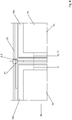
- FIGS 3 and 4 show another embodiment of a swing door system 2.
- the swing door system 2 comprises two adjacent swing doors 1a, 1b, wherein each swing door 1a, 1b includes transparent panes 3a, 3b being spaced from each other by spacers 4a, 4b.
- a mullion 5 is arranged.
- the mullion 5 is T-shaped and comprises a part 6 that reaches between the adjacent swing doors 1a, 1b, when the swing doors 1a, 1b are in the closed position. It is possible that the part 6 is shorter, such that it does not reach in between the adjacent swing doors 1a, 1b.
- the depth 30 of the mullion 5 is shorter than the depth 11 of the non-transparent region 9.
- the width 31 of the mullion 5 equals the width 12 of the non-transparent region 9.
- the mullion further comprises sealing surfaces 7a, 7b onto which the gaskets 8a, 8b are fixed, for example glued or snapped into.
- the adjacent swing doors include wedges 23a, 23b that are made of a material that interacts with the magnets 13a, 13b of the gaskets.
- the wedges 23a, 23b are made of steel.
- the sealing surfaces 7a, 7b of the mullion 5 are inclined with respect to the transparent panes 3a, 3b when the adjacent swing doors 1a, 1b are in the closed position.
- Figure 4 further shows that the left swing door 1 comprises a hinge element 21, such that the swing door 1a can be rotatable mounted to horizontal profile 22 of an outer frame.
- the right swing door 1b can comprise a hinge on its not shown right side.
- FIGS 5 and 6 show another embodiment of a swing door system 2.
- the swing door system 2 comprises two adjacent swing doors 1a, 1b, wherein each swing door 1a, 1b includes transparent panes 3a, 3b being spaced from each other by spacers 4a, 4b.
- a mullion 5 is arranged.
- the mullion 5 is T-shaped and comprises a part 6 that reaches between the adjacent swing doors 1a, 1b, when the swing doors 1a, 1b are in the closed position.
- the depth 30 of the mullion 5 is shorter than the depth 11 of the non-transparent region 9.
- the width 31 of the mullion 5 equals the width 12 of the non-transparent region 9.
- the swing door system 2 corresponds to the embodiment shown in figures 1 and 2 .
- the rotating axis of the left door 1a is arranged between the adjacent swing doors 1a, 1b.
- shear forces are minimized that are acting on the gaskets 8a, 8b when the swing doors 1a, 1b are opened and the right door 1b is prevented from blocking the left door 1a, when the left door 1 is opened.
- Figure 6 further shows that the left swing door 1 comprises a hinge 21, such that the swing door 1a can be rotatable mounted to a horizontal profile 22 of an outer frame.
- the right swing door 1b can comprise a hinge on its not shown right side.
- Figure 7 shows a cross-sectional view parallel to the opening direction of a mullion 5 according to a further embodiment of the present invention.
- the mullion 5 has a triangle shaped cross section. Therefore, the sealing surfaces 7a, 7b of the mullion 5 are inclined with respect to the not shown transparent pane of the adjacent swing doors when the swing doors are in the closed position.
- a triangle shaped mullion 5 has the advantage that the inner part 24 of the mullion 5 can serve as a cable duct, heat pipes, heating elements or other elements.
- Figure 8 shows a cross-sectional view parallel to the opening direction of a mullion 5 according to a further embodiment of the present invention.
- the mullion 5 has a Y-shaped cross section. Therefore, the sealing surfaces 7a, 7b of the mullion 5 are inclined with respect to the not shown pane of the adjacent swing doors when the swing doors are in the closed position.
- the part 6 of the Y-shaped mullion 5 can reach in between the not shown adjacent swing doors. Furthermore, part 6 can be realized shorter, such that it does not reach in between the adjacent swing doors.
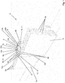
- FIG 9 shows a perspective view of a freezer device 25 according to an embodiment of the present invention.
- the freezer device 25 comprises a cabinet 26 and three swing door systems 2 each including two adjacent swing doors 1a, 1b and a mullion 5.
- the customer can see the products 27 through the transparent panes 3a, 3b of the swing doors 1a, 1b. Due to the low depth 11 and low width 12 of the non-transparent region 9, the person's view of the products 27 is improved when the person is viewing slantwise into the freezer device 2. Furthermore, the low width 12 of the non-transparent region 9 improves the view on the products 27, when the person stands in front of the freezer device 2.
- the freezer device 2 comprises an energy source 28 that is connected with an interface 29, which enables to provide energy to a heating element and/or light elements inside the swing doors 1a, 1b.
- figure 10 serves to illustrate the plurality of horizontal see-through angles 33.
- Figure 10 shows several adjacent swing doors 1a, 1b, each comprising a transparent pane 3a, 3b and a gasket 8a, 8b.
- the shown element 8a, 8b being described as a gasket is not limited as such and can therefore be any element defining the corresponding portion of the non-transparent region, for example a profile, a print or the like.
- figure 10 shows mullions 5 being in contact with two of said adjacent swing doors 1a, 1b.
- the mullion 5 and the swing doors 1a, 1b define non-transparent regions 9. It should be noted that on the very left and/or the very right of a freezer device the non-transparent region 9 could be defined by a vertical side and the swing door 1a, 1b being in contact with this vertical side.
- FIG. 10 shows the maximum see-through angle 32 and the minimum see-through angle 32'.
- a view through the transparent pane 3a is not blocked by the non-transparent region 9 under a plurality of horizontal see-through angles 33 that range from the maximum see-through angle 32 to the minimum see-through angle 32'.
- Under a viewing angle bigger than the maximum see-through angle 32 or smaller than the minimum see-through angle 32' the view through the transparent pane 3a is totally blocked by the non-transparent region 9.
- the maximum and minimum see-through angles 32, 32' depend on the width 34 of the swing door 1a, the width 12 of the non-transparent region 9 and the depth 11 of the non-transparent region 9.
Landscapes
- Physics & Mathematics (AREA)
- Thermal Sciences (AREA)
- Refrigerator Housings (AREA)
- Wing Frames And Configurations (AREA)
Priority Applications (7)
| Application Number | Priority Date | Filing Date | Title |
|---|---|---|---|
| EP19172776.7A EP3735866B1 (fr) | 2019-05-06 | 2019-05-06 | Système de porte battante et dispositif de congélateur |
| DE202019105362.3U DE202019105362U1 (de) | 2019-05-06 | 2019-09-27 | Schwingtürsystem und eine Tiefkühlvorrichtung |
| DE202019105965.6U DE202019105965U1 (de) | 2019-05-06 | 2019-10-28 | Schwingtürsystem und eine Tiefkühlvorrichtung |
| BR112021022155A BR112021022155A2 (pt) | 2019-05-06 | 2020-03-23 | Sistema de porta oscilante e um dispositivo congelador |
| AU2020268503A AU2020268503A1 (en) | 2019-05-06 | 2020-03-23 | Swing door system and a freezer device |
| PCT/EP2020/057925 WO2020224847A1 (fr) | 2019-05-06 | 2020-03-23 | Système de portes battantes et dispositif congélateur |
| US17/521,067 US20220053949A1 (en) | 2019-05-06 | 2021-11-08 | Swing door system and a freezer device |
Applications Claiming Priority (1)
| Application Number | Priority Date | Filing Date | Title |
|---|---|---|---|
| EP19172776.7A EP3735866B1 (fr) | 2019-05-06 | 2019-05-06 | Système de porte battante et dispositif de congélateur |
Publications (2)
| Publication Number | Publication Date |
|---|---|
| EP3735866A1 true EP3735866A1 (fr) | 2020-11-11 |
| EP3735866B1 EP3735866B1 (fr) | 2021-06-30 |
Family
ID=66429268
Family Applications (1)
| Application Number | Title | Priority Date | Filing Date |
|---|---|---|---|
| EP19172776.7A Active EP3735866B1 (fr) | 2019-05-06 | 2019-05-06 | Système de porte battante et dispositif de congélateur |
Country Status (6)
| Country | Link |
|---|---|
| US (1) | US20220053949A1 (fr) |
| EP (1) | EP3735866B1 (fr) |
| AU (1) | AU2020268503A1 (fr) |
| BR (1) | BR112021022155A2 (fr) |
| DE (2) | DE202019105362U1 (fr) |
| WO (1) | WO2020224847A1 (fr) |
Citations (4)
| Publication number | Priority date | Publication date | Assignee | Title |
|---|---|---|---|---|
| US6029411A (en) * | 1992-03-12 | 2000-02-29 | Anthony, Inc. | Composite door and frame |
| US20100018232A1 (en) * | 2008-07-25 | 2010-01-28 | Hussmann Corporation | Mullion assembly for a refrigerated merchandiser |
| US20110043089A1 (en) * | 2009-08-19 | 2011-02-24 | Chubb Richard A | Reach-in door for refrigerated cabinets |
| US20190059613A1 (en) * | 2017-08-29 | 2019-02-28 | Anthony, Inc. | Glass assembly with clear edging |
Family Cites Families (11)
| Publication number | Priority date | Publication date | Assignee | Title |
|---|---|---|---|---|
| US4223482A (en) * | 1978-01-16 | 1980-09-23 | Barroero Louis F | Refrigerator door structure |
| US4831780A (en) * | 1987-07-07 | 1989-05-23 | Ardco Inc. | Refrigerator door assembly with thermal break frame |
| US6637093B2 (en) * | 1998-03-03 | 2003-10-28 | Anthony, Inc. | Method of assembling a display case door |
| US6148563A (en) * | 1999-03-25 | 2000-11-21 | Hussmann Corporation | Reach-in door for refrigerated merchandiser |
| AUPQ459599A0 (en) * | 1999-12-09 | 2000-01-13 | Orford Pty Ltd | Improved mullion assembly |
| US20010048595A1 (en) * | 2000-06-02 | 2001-12-06 | Richardson Richard J. | Methods and apparatus for illuminating an area |
| US20030062813A1 (en) * | 2001-07-19 | 2003-04-03 | Cording Christopher R. | Energy-free refrigeration door and method for making the same |
| US9157675B2 (en) * | 2010-06-09 | 2015-10-13 | Hill Phoenix, Inc. | Insulated case construction |
| US8869493B2 (en) * | 2012-03-14 | 2014-10-28 | Thermoseal Industries, L.L.C. | Door for a refrigerated cabinet |
| US9890914B2 (en) * | 2013-01-18 | 2018-02-13 | Raves Equipment Company | Lighting assembly |
| US9955803B2 (en) * | 2014-12-15 | 2018-05-01 | Hussmann Corporation | Door for a refrigerated merchandiser |
-
2019
- 2019-05-06 EP EP19172776.7A patent/EP3735866B1/fr active Active
- 2019-09-27 DE DE202019105362.3U patent/DE202019105362U1/de active Active
- 2019-10-28 DE DE202019105965.6U patent/DE202019105965U1/de active Active
-
2020
- 2020-03-23 BR BR112021022155A patent/BR112021022155A2/pt unknown
- 2020-03-23 WO PCT/EP2020/057925 patent/WO2020224847A1/fr active Application Filing
- 2020-03-23 AU AU2020268503A patent/AU2020268503A1/en active Pending
-
2021
- 2021-11-08 US US17/521,067 patent/US20220053949A1/en active Pending
Patent Citations (4)
| Publication number | Priority date | Publication date | Assignee | Title |
|---|---|---|---|---|
| US6029411A (en) * | 1992-03-12 | 2000-02-29 | Anthony, Inc. | Composite door and frame |
| US20100018232A1 (en) * | 2008-07-25 | 2010-01-28 | Hussmann Corporation | Mullion assembly for a refrigerated merchandiser |
| US20110043089A1 (en) * | 2009-08-19 | 2011-02-24 | Chubb Richard A | Reach-in door for refrigerated cabinets |
| US20190059613A1 (en) * | 2017-08-29 | 2019-02-28 | Anthony, Inc. | Glass assembly with clear edging |
Also Published As
| Publication number | Publication date |
|---|---|
| EP3735866B1 (fr) | 2021-06-30 |
| WO2020224847A1 (fr) | 2020-11-12 |
| BR112021022155A2 (pt) | 2022-04-12 |
| DE202019105362U1 (de) | 2019-10-23 |
| DE202019105965U1 (de) | 2019-11-07 |
| AU2020268503A1 (en) | 2021-12-23 |
| US20220053949A1 (en) | 2022-02-24 |
Similar Documents
| Publication | Publication Date | Title |
|---|---|---|
| EP3450892B1 (fr) | Porte de vitrine réfrigérée et vitrine réfrigérée | |
| US6435630B1 (en) | Climatic condition reproducer cabinet | |
| US20170150828A1 (en) | Display case door assembly with vacuum panel | |
| US20180340365A1 (en) | Insulating glass unit for a refrigeration unit | |
| EP3735869A1 (fr) | Système de porte battante et dispositif de congélateur | |
| CN1820173A (zh) | 具有隔离玻璃的门和装备此门的家用器具 | |
| US10888176B2 (en) | Heat absorbing door for a refrigerated merchandiser | |
| US20060103269A1 (en) | Soft-coated glass pane refrigerator door construction and method of making same | |
| AU2012284427A1 (en) | Heat absorbing door for a refrigerated merchandiser | |
| EP3735866B1 (fr) | Système de porte battante et dispositif de congélateur | |
| EP3733022A1 (fr) | Système de porte battante et dispositif de congélation comportant un système de porte battante | |
| EP3730731A1 (fr) | Unité de double vitrage transparente améliorée | |
| KR20190083728A (ko) | 냉장 및 냉동고용 유리 도어 | |
| US20220090846A1 (en) | Swing door system and device with a swing door system | |
| BR112021007694A2 (pt) | vidraça isolada que forma um painel de abertura de porta ou janela, que é sem moldura em pelo menos uma parte da sua periferia | |
| NZ618999B2 (en) | Heat absorbing door for a refrigerated merchandiser |
Legal Events
| Date | Code | Title | Description |
|---|---|---|---|
| STAA | Information on the status of an ep patent application or granted ep patent |
Free format text: STATUS: EXAMINATION IS IN PROGRESS |
|
| PUAI | Public reference made under article 153(3) epc to a published international application that has entered the european phase |
Free format text: ORIGINAL CODE: 0009012 |
|
| 17P | Request for examination filed |
Effective date: 20190528 |
|
| AK | Designated contracting states |
Kind code of ref document: A1 Designated state(s): AL AT BE BG CH CY CZ DE DK EE ES FI FR GB GR HR HU IE IS IT LI LT LU LV MC MK MT NL NO PL PT RO RS SE SI SK SM TR |
|
| AX | Request for extension of the european patent |
Extension state: BA ME |
|
| GRAP | Despatch of communication of intention to grant a patent |
Free format text: ORIGINAL CODE: EPIDOSNIGR1 |
|
| STAA | Information on the status of an ep patent application or granted ep patent |
Free format text: STATUS: GRANT OF PATENT IS INTENDED |
|
| INTG | Intention to grant announced |
Effective date: 20210121 |
|
| RAP1 | Party data changed (applicant data changed or rights of an application transferred) |
Owner name: SCHOTT FLAT GLASS CR, S.R.O. Owner name: SCHOTT AG |
|
| RIN1 | Information on inventor provided before grant (corrected) |
Inventor name: LEDERHOFER, LEDERHOFER Inventor name: RAFAJ, MARTIN Inventor name: HELLER, MARKUS Inventor name: LAMMEL, MICHAEL Inventor name: SMAJSER, PETR Inventor name: DIEDERICHS, JOCHEN |
|
| GRAS | Grant fee paid |
Free format text: ORIGINAL CODE: EPIDOSNIGR3 |
|
| GRAA | (expected) grant |
Free format text: ORIGINAL CODE: 0009210 |
|
| STAA | Information on the status of an ep patent application or granted ep patent |
Free format text: STATUS: THE PATENT HAS BEEN GRANTED |
|
| AK | Designated contracting states |
Kind code of ref document: B1 Designated state(s): AL AT BE BG CH CY CZ DE DK EE ES FI FR GB GR HR HU IE IS IT LI LT LU LV MC MK MT NL NO PL PT RO RS SE SI SK SM TR |
|
| REG | Reference to a national code |
Ref country code: CH Ref legal event code: EP |
|
| RIN1 | Information on inventor provided before grant (corrected) |
Inventor name: DIEDERICHS, JOCHEN Inventor name: SMAJSER, PETR Inventor name: RAFAJ, MARTIN Inventor name: LAMMEL, MICHAEL Inventor name: LEDERHOFER, BENJAMIN Inventor name: HELLER, MARKUS |
|
| REG | Reference to a national code |
Ref country code: AT Ref legal event code: REF Ref document number: 1405538 Country of ref document: AT Kind code of ref document: T Effective date: 20210715 |
|
| REG | Reference to a national code |
Ref country code: DE Ref legal event code: R096 Ref document number: 602019005664 Country of ref document: DE |
|
| REG | Reference to a national code |
Ref country code: IE Ref legal event code: FG4D |
|
| REG | Reference to a national code |
Ref country code: LT Ref legal event code: MG9D |
|
| PG25 | Lapsed in a contracting state [announced via postgrant information from national office to epo] |
Ref country code: FI Free format text: LAPSE BECAUSE OF FAILURE TO SUBMIT A TRANSLATION OF THE DESCRIPTION OR TO PAY THE FEE WITHIN THE PRESCRIBED TIME-LIMIT Effective date: 20210630 Ref country code: HR Free format text: LAPSE BECAUSE OF FAILURE TO SUBMIT A TRANSLATION OF THE DESCRIPTION OR TO PAY THE FEE WITHIN THE PRESCRIBED TIME-LIMIT Effective date: 20210630 Ref country code: BG Free format text: LAPSE BECAUSE OF FAILURE TO SUBMIT A TRANSLATION OF THE DESCRIPTION OR TO PAY THE FEE WITHIN THE PRESCRIBED TIME-LIMIT Effective date: 20210930 |
|
| REG | Reference to a national code |
Ref country code: NL Ref legal event code: MP Effective date: 20210630 |
|
| REG | Reference to a national code |
Ref country code: AT Ref legal event code: MK05 Ref document number: 1405538 Country of ref document: AT Kind code of ref document: T Effective date: 20210630 |
|
| PG25 | Lapsed in a contracting state [announced via postgrant information from national office to epo] |
Ref country code: RS Free format text: LAPSE BECAUSE OF FAILURE TO SUBMIT A TRANSLATION OF THE DESCRIPTION OR TO PAY THE FEE WITHIN THE PRESCRIBED TIME-LIMIT Effective date: 20210630 Ref country code: SE Free format text: LAPSE BECAUSE OF FAILURE TO SUBMIT A TRANSLATION OF THE DESCRIPTION OR TO PAY THE FEE WITHIN THE PRESCRIBED TIME-LIMIT Effective date: 20210630 Ref country code: NO Free format text: LAPSE BECAUSE OF FAILURE TO SUBMIT A TRANSLATION OF THE DESCRIPTION OR TO PAY THE FEE WITHIN THE PRESCRIBED TIME-LIMIT Effective date: 20210930 Ref country code: LV Free format text: LAPSE BECAUSE OF FAILURE TO SUBMIT A TRANSLATION OF THE DESCRIPTION OR TO PAY THE FEE WITHIN THE PRESCRIBED TIME-LIMIT Effective date: 20210630 Ref country code: GR Free format text: LAPSE BECAUSE OF FAILURE TO SUBMIT A TRANSLATION OF THE DESCRIPTION OR TO PAY THE FEE WITHIN THE PRESCRIBED TIME-LIMIT Effective date: 20211001 |
|
| PG25 | Lapsed in a contracting state [announced via postgrant information from national office to epo] |
Ref country code: PT Free format text: LAPSE BECAUSE OF FAILURE TO SUBMIT A TRANSLATION OF THE DESCRIPTION OR TO PAY THE FEE WITHIN THE PRESCRIBED TIME-LIMIT Effective date: 20211102 Ref country code: NL Free format text: LAPSE BECAUSE OF FAILURE TO SUBMIT A TRANSLATION OF THE DESCRIPTION OR TO PAY THE FEE WITHIN THE PRESCRIBED TIME-LIMIT Effective date: 20210630 Ref country code: RO Free format text: LAPSE BECAUSE OF FAILURE TO SUBMIT A TRANSLATION OF THE DESCRIPTION OR TO PAY THE FEE WITHIN THE PRESCRIBED TIME-LIMIT Effective date: 20210630 Ref country code: SM Free format text: LAPSE BECAUSE OF FAILURE TO SUBMIT A TRANSLATION OF THE DESCRIPTION OR TO PAY THE FEE WITHIN THE PRESCRIBED TIME-LIMIT Effective date: 20210630 Ref country code: AT Free format text: LAPSE BECAUSE OF FAILURE TO SUBMIT A TRANSLATION OF THE DESCRIPTION OR TO PAY THE FEE WITHIN THE PRESCRIBED TIME-LIMIT Effective date: 20210630 Ref country code: ES Free format text: LAPSE BECAUSE OF FAILURE TO SUBMIT A TRANSLATION OF THE DESCRIPTION OR TO PAY THE FEE WITHIN THE PRESCRIBED TIME-LIMIT Effective date: 20210630 Ref country code: EE Free format text: LAPSE BECAUSE OF FAILURE TO SUBMIT A TRANSLATION OF THE DESCRIPTION OR TO PAY THE FEE WITHIN THE PRESCRIBED TIME-LIMIT Effective date: 20210630 Ref country code: SK Free format text: LAPSE BECAUSE OF FAILURE TO SUBMIT A TRANSLATION OF THE DESCRIPTION OR TO PAY THE FEE WITHIN THE PRESCRIBED TIME-LIMIT Effective date: 20210630 |
|
| PG25 | Lapsed in a contracting state [announced via postgrant information from national office to epo] |
Ref country code: PL Free format text: LAPSE BECAUSE OF FAILURE TO SUBMIT A TRANSLATION OF THE DESCRIPTION OR TO PAY THE FEE WITHIN THE PRESCRIBED TIME-LIMIT Effective date: 20210630 |
|
| REG | Reference to a national code |
Ref country code: DE Ref legal event code: R097 Ref document number: 602019005664 Country of ref document: DE |
|
| PG25 | Lapsed in a contracting state [announced via postgrant information from national office to epo] |
Ref country code: DK Free format text: LAPSE BECAUSE OF FAILURE TO SUBMIT A TRANSLATION OF THE DESCRIPTION OR TO PAY THE FEE WITHIN THE PRESCRIBED TIME-LIMIT Effective date: 20210630 |
|
| PLBE | No opposition filed within time limit |
Free format text: ORIGINAL CODE: 0009261 |
|
| STAA | Information on the status of an ep patent application or granted ep patent |
Free format text: STATUS: NO OPPOSITION FILED WITHIN TIME LIMIT |
|
| PG25 | Lapsed in a contracting state [announced via postgrant information from national office to epo] |
Ref country code: AL Free format text: LAPSE BECAUSE OF FAILURE TO SUBMIT A TRANSLATION OF THE DESCRIPTION OR TO PAY THE FEE WITHIN THE PRESCRIBED TIME-LIMIT Effective date: 20210630 |
|
| 26N | No opposition filed |
Effective date: 20220331 |
|
| REG | Reference to a national code |
Ref country code: CH Ref legal event code: PL |
|
| REG | Reference to a national code |
Ref country code: BE Ref legal event code: MM Effective date: 20220531 |
|
| PG25 | Lapsed in a contracting state [announced via postgrant information from national office to epo] |
Ref country code: MC Free format text: LAPSE BECAUSE OF FAILURE TO SUBMIT A TRANSLATION OF THE DESCRIPTION OR TO PAY THE FEE WITHIN THE PRESCRIBED TIME-LIMIT Effective date: 20210630 Ref country code: LU Free format text: LAPSE BECAUSE OF NON-PAYMENT OF DUE FEES Effective date: 20220506 Ref country code: LI Free format text: LAPSE BECAUSE OF NON-PAYMENT OF DUE FEES Effective date: 20220531 Ref country code: CH Free format text: LAPSE BECAUSE OF NON-PAYMENT OF DUE FEES Effective date: 20220531 |
|
| PG25 | Lapsed in a contracting state [announced via postgrant information from national office to epo] |
Ref country code: LT Free format text: LAPSE BECAUSE OF FAILURE TO SUBMIT A TRANSLATION OF THE DESCRIPTION OR TO PAY THE FEE WITHIN THE PRESCRIBED TIME-LIMIT Effective date: 20210630 Ref country code: IE Free format text: LAPSE BECAUSE OF NON-PAYMENT OF DUE FEES Effective date: 20220506 |
|
| PG25 | Lapsed in a contracting state [announced via postgrant information from national office to epo] |
Ref country code: BE Free format text: LAPSE BECAUSE OF NON-PAYMENT OF DUE FEES Effective date: 20220531 |
|
| P01 | Opt-out of the competence of the unified patent court (upc) registered |
Effective date: 20230516 |
|
| PGFP | Annual fee paid to national office [announced via postgrant information from national office to epo] |
Ref country code: IT Payment date: 20230526 Year of fee payment: 5 Ref country code: FR Payment date: 20230526 Year of fee payment: 5 Ref country code: DE Payment date: 20230519 Year of fee payment: 5 Ref country code: CZ Payment date: 20230502 Year of fee payment: 5 |
|
| PGFP | Annual fee paid to national office [announced via postgrant information from national office to epo] |
Ref country code: GB Payment date: 20230524 Year of fee payment: 5 |
|
| PG25 | Lapsed in a contracting state [announced via postgrant information from national office to epo] |
Ref country code: MK Free format text: LAPSE BECAUSE OF FAILURE TO SUBMIT A TRANSLATION OF THE DESCRIPTION OR TO PAY THE FEE WITHIN THE PRESCRIBED TIME-LIMIT Effective date: 20210630 Ref country code: CY Free format text: LAPSE BECAUSE OF FAILURE TO SUBMIT A TRANSLATION OF THE DESCRIPTION OR TO PAY THE FEE WITHIN THE PRESCRIBED TIME-LIMIT Effective date: 20210630 |