EP3735819A1 - Hybrid agricultural vehicle for baler application - Google Patents
Hybrid agricultural vehicle for baler application Download PDFInfo
- Publication number
- EP3735819A1 EP3735819A1 EP20173802.8A EP20173802A EP3735819A1 EP 3735819 A1 EP3735819 A1 EP 3735819A1 EP 20173802 A EP20173802 A EP 20173802A EP 3735819 A1 EP3735819 A1 EP 3735819A1
- Authority
- EP
- European Patent Office
- Prior art keywords
- designed
- torque
- ice
- des
- speed
- Prior art date
- Legal status (The legal status is an assumption and is not a legal conclusion. Google has not performed a legal analysis and makes no representation as to the accuracy of the status listed.)
- Granted
Links
- 238000002485 combustion reaction Methods 0.000 claims abstract description 9
- 238000004146 energy storage Methods 0.000 claims description 5
- 230000009347 mechanical transmission Effects 0.000 claims description 3
- 230000013011 mating Effects 0.000 description 3
- 230000005540 biological transmission Effects 0.000 description 2
- 238000000034 method Methods 0.000 description 2
- 229920000742 Cotton Polymers 0.000 description 1
- 241000196324 Embryophyta Species 0.000 description 1
- 241000208202 Linaceae Species 0.000 description 1
- 235000004431 Linum usitatissimum Nutrition 0.000 description 1
- 235000016709 nutrition Nutrition 0.000 description 1
- 150000003839 salts Chemical class 0.000 description 1
- 239000004460 silage Substances 0.000 description 1
- 239000010902 straw Substances 0.000 description 1
Images


Classifications
-
- A—HUMAN NECESSITIES
- A01—AGRICULTURE; FORESTRY; ANIMAL HUSBANDRY; HUNTING; TRAPPING; FISHING
- A01F—PROCESSING OF HARVESTED PRODUCE; HAY OR STRAW PRESSES; DEVICES FOR STORING AGRICULTURAL OR HORTICULTURAL PRODUCE
- A01F15/00—Baling presses for straw, hay or the like
- A01F15/08—Details
- A01F15/0841—Drives for balers
-
- A—HUMAN NECESSITIES
- A01—AGRICULTURE; FORESTRY; ANIMAL HUSBANDRY; HUNTING; TRAPPING; FISHING
- A01F—PROCESSING OF HARVESTED PRODUCE; HAY OR STRAW PRESSES; DEVICES FOR STORING AGRICULTURAL OR HORTICULTURAL PRODUCE
- A01F15/00—Baling presses for straw, hay or the like
- A01F15/04—Plunger presses
- A01F15/042—Plungers
-
- B—PERFORMING OPERATIONS; TRANSPORTING
- B30—PRESSES
- B30B—PRESSES IN GENERAL
- B30B9/00—Presses specially adapted for particular purposes
- B30B9/30—Presses specially adapted for particular purposes for baling; Compression boxes therefor
- B30B9/3003—Details
- B30B9/3007—Control arrangements
-
- E—FIXED CONSTRUCTIONS
- E02—HYDRAULIC ENGINEERING; FOUNDATIONS; SOIL SHIFTING
- E02F—DREDGING; SOIL-SHIFTING
- E02F9/00—Component parts of dredgers or soil-shifting machines, not restricted to one of the kinds covered by groups E02F3/00 - E02F7/00
- E02F9/20—Drives; Control devices
- E02F9/2058—Electric or electro-mechanical or mechanical control devices of vehicle sub-units
- E02F9/2062—Control of propulsion units
- E02F9/207—Control of propulsion units of the type electric propulsion units, e.g. electric motors or generators
-
- E—FIXED CONSTRUCTIONS
- E02—HYDRAULIC ENGINEERING; FOUNDATIONS; SOIL SHIFTING
- E02F—DREDGING; SOIL-SHIFTING
- E02F9/00—Component parts of dredgers or soil-shifting machines, not restricted to one of the kinds covered by groups E02F3/00 - E02F7/00
- E02F9/20—Drives; Control devices
- E02F9/2058—Electric or electro-mechanical or mechanical control devices of vehicle sub-units
- E02F9/2062—Control of propulsion units
- E02F9/2075—Control of propulsion units of the hybrid type
-
- E—FIXED CONSTRUCTIONS
- E02—HYDRAULIC ENGINEERING; FOUNDATIONS; SOIL SHIFTING
- E02F—DREDGING; SOIL-SHIFTING
- E02F9/00—Component parts of dredgers or soil-shifting machines, not restricted to one of the kinds covered by groups E02F3/00 - E02F7/00
- E02F9/20—Drives; Control devices
- E02F9/2058—Electric or electro-mechanical or mechanical control devices of vehicle sub-units
- E02F9/2095—Control of electric, electro-mechanical or mechanical equipment not otherwise provided for, e.g. ventilators, electro-driven fans
-
- Y—GENERAL TAGGING OF NEW TECHNOLOGICAL DEVELOPMENTS; GENERAL TAGGING OF CROSS-SECTIONAL TECHNOLOGIES SPANNING OVER SEVERAL SECTIONS OF THE IPC; TECHNICAL SUBJECTS COVERED BY FORMER USPC CROSS-REFERENCE ART COLLECTIONS [XRACs] AND DIGESTS
- Y02—TECHNOLOGIES OR APPLICATIONS FOR MITIGATION OR ADAPTATION AGAINST CLIMATE CHANGE
- Y02P—CLIMATE CHANGE MITIGATION TECHNOLOGIES IN THE PRODUCTION OR PROCESSING OF GOODS
- Y02P70/00—Climate change mitigation technologies in the production process for final industrial or consumer products
- Y02P70/10—Greenhouse gas [GHG] capture, material saving, heat recovery or other energy efficient measures, e.g. motor control, characterised by manufacturing processes, e.g. for rolling metal or metal working
Definitions
- the present invention concerns a hybrid agricultural vehicle for baler application.
- a baler most often called a hay baler, is a piece of farm machinery used to compress a cut and raked crop (such as hay, cotton, flax straw, salt marsh hay, or silage) into compact bales that are easy to handle, transport, and store. Often, bales are configured to dry and preserve some intrinsic (e.g. the nutritional) value of the plants bundled.
- balers are commonly used, each producing a different type of bale - rectangular or cylindrical, of various sizes, bound with twine, strapping, netting, or wire.
- the baler is normally towed by an agricultural vehicle (normally a tractor) and is powered by the PTO of the tractor.
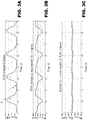
- a common feature of the baler is that it requires a highly variable torque that is severely undulating between a higher value corresponding to a starting phase crop pressing to a lower value corresponding to the end of the pressing phase (we refer to figure 3A ).
- This request of variable torque produces a variation of the speed of the motor (we refer to figure 3B ) of the tractor that cause a corresponding undulation of the speed of the tractor.
- Scope of the present invention is to provide a vehicle for baler application that may reduce the undulation of the speed of the motor of the vehicle.
- the desired speed is indicated with dotted line).
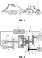
- numeral 1 indicates a Hybrid agricultural vehicle, for instance a tractor, provided with a baler 2.
- the vehicle comprises schematically ( figure 2 ) an internal combustion engine 3 (typically a diesel engine) having an output shaft 4 that is connected through a first mechanical transmission 5 with an input shaft 6 of an electric motor 7 acting as a voltage generator in order to produce electrical power.
- the mechanical transmission 5 has been schematized by means of a first gear 8 mounted on output shaft 4 and having radius r r and mating with a second gear 9 mounted on output shaft 6 and having radius r f .
- the generator 7 produces alternating voltage that is fed to a rectifier 10 that supplies the DC voltage to an electric energy storage unit 11 that is designed to store the electric power produced by the electric generator 7.
- the energy storage unit 11 may comprises supercapacitors or batteries.
- An electric motor 12 is powered by a power control electronics 13 by the energy provided by the electric generator 7 and drawn from the electrical energy storage unit 11.
- An epicyclic converter 14 has:
- the output shaft 21 of the electric motor 12 is connected with the second input member 17 by means of a second transmission 22 that has been schematized by means of a third gear 23 mounted on the output shaft 21 and having radius r m and mating with a fourth gear 24 mounted on an output shaft 25 and having radius r t .
- Clutch 18 is interposed between the output shaft 25 and the sun gear shaft 17 (second input member).
- the output member 19 of the epicyclic converter 14 is connected with a PTO shaft 25 by means of a third transmission 26 that has been schematized by means of a geared portion of the output planetary carrier shaft 19 mating with a fifth gear 28 mounted on the PTO shaft 25.
- the baler requires a variable torque that is undulating with a period ⁇ between a higher value h ( figure 3A ) corresponding to a starting phase crop pressing to a lower value v corresponding to the end of the pressing.
- control electronics 13 is designed to control the torque supplied by the electric motor 12 so that the torque provided to the second input member 17 compensates torque request from the baler 2 so that the rotating speed of the internal combustion engine 3 remains substantially stable ( figure 3B full line, the dotted line represent the desired speed) even if the torque requested by the baler is undulating.
- the extra energy necessary to mate with the baler torque request is drawn from the supercapacitor 11.
- Figure 4 shows a control logic of power control electronics 12 performing the control from the side of the epicyclic convertor 14 towards the electric machine (electric motor) 12.
- the speed of the shaft 25 is measured by means of a sensor 30 and the measured speed ⁇ m1 is compared in a differential block 31 with a set speed ⁇ m1-des and a difference signal ⁇ m1 is produced.
- the difference signal ⁇ m1 is provided to a PID block 32 that produces at its output a signal T m1_des that represents the torque increment necessary to keep the speed constant, i.e. minimizing ⁇ m1 .
- the output a signal T m1_des is provided to a fist converter block 33 that produces - using know techniques - a current vector I s1-des that represents the current that has to be supplied by the electric motor 12 for obtaining the desired torque increment.
- the current vector I s1-des is compared (block 34) with the real current vector I s1 that is present and measured in the electric motor 12 and the difference ⁇ I s1 is supplied to a second converter block 35 that calculates the voltage V s1 that has to be supplied to the motor 12 to compensate the torque request and keep the speed of the PTO shaft 20 constant.
- Figure 5 shows the speed & torque loop of the control logic of power control electronics 13 performing the control from the side of the epicyclic convertor 14 towards the electric machine (electric generator) 7.
- the speed of the shaft 4 is measured by means of a sensor 40 and the measured speed ⁇ ice is compared in a differential block 41 with a set speed ⁇ ice-des and a difference signal ⁇ ice is produced.
- Set point ⁇ ice-des is calculated as function of the current ICE Power required.
- the difference signal ⁇ ice is provided to a PI block 42 that produces at its output a signal T ice_dem that represents the torque requested by the internal combustion engine 7 (ICE) during its operation.
- ICE internal combustion engine 7
- the output signal T ice_dem is provided to another comparison block 43 that compares the signal T ice_dem with a target signal T ice_des and produces a difference signal ⁇ T_ice.
- This signal ⁇ T_ice - using know techniques - is converted into a current vector Is 2-des that represents the current that has to be supplied by the electric machine (electric generator) 7 for obtaining the desired torque adjustment.
- the current vector I s2-des is compared (block 45) with the real current vector I s2 that is present and measured in the electric generator 7 (E.M.2) and the difference ⁇ I s2 is supplied to a second converter block 46 that calculates the voltage V s2 that has to be supplied to the electric generator 7 (E.M.2) to compensate the torque request and keep the speed of the ICE shaft 4 constant or controlled.
- the torque loop on E.M.2 allow to compensate the torque peak on the ICE Side, while the Speed loop on the ICE, allow to control the ICE Engine Speed.
Abstract
a first input member (15) that is designed to receive torque from an internal combustion engine; a second input member (17) that is designed to receive torque from an electric motor (12); and an output member (19) that is designed to provide the input torques to the Power Torque Output PTO (20). The baler requires a variable torque that is undulating with a period τ between a higher value corresponding to a starting phase crop pressing to a lower value corresponding to the end of the pressing phase. A control electronics (13) is designed to control the torque supplied by the electric motor so that the torque provided to the second input member compensates torque request from the baler (2) and the torque provided to the second input member has a number of peaks in correspondence of the higher values of the torque required by the baler so that the rotating speed of the internal combustion engine substantially stable even if the torque requested by the baler is undulating.
Description
- The present invention concerns a hybrid agricultural vehicle for baler application.
- A baler, most often called a hay baler, is a piece of farm machinery used to compress a cut and raked crop (such as hay, cotton, flax straw, salt marsh hay, or silage) into compact bales that are easy to handle, transport, and store. Often, bales are configured to dry and preserve some intrinsic (e.g. the nutritional) value of the plants bundled. Several different types of balers are commonly used, each producing a different type of bale - rectangular or cylindrical, of various sizes, bound with twine, strapping, netting, or wire.
- The baler is normally towed by an agricultural vehicle (normally a tractor) and is powered by the PTO of the tractor.
- A common feature of the baler is that it requires a highly variable torque that is severely undulating between a higher value corresponding to a starting phase crop pressing to a lower value corresponding to the end of the pressing phase (we refer to
figure 3A ). This request of variable torque produces a variation of the speed of the motor (we refer tofigure 3B ) of the tractor that cause a corresponding undulation of the speed of the tractor. - This "start and stop" motion of the tractor is quite undesirable as it produces an evident discomfort to the driver.
- Scope of the present invention is to provide a vehicle for baler application that may reduce the undulation of the speed of the motor of the vehicle. In
figure 3B the desired speed is indicated with dotted line). - The aforementioned aim is reached by the present invention as claimed in the appended set of claims.
- For a better understanding of the present invention, a preferred embodiment is described in the following, by way of a non-limiting example, with reference to the attached drawings wherein:
-
Figure 1 shows schematically an agricultural vehicle provided with a baler; -
Figure 2 is a simplified schema of a hybrid agricultural vehicle realized for baler application according to the present invention; -
Figures 3A, 3B and 3C show different values controlled; -
Figure 4 represents a first part of the control logic; and -
Figure 5 represents a second part of the control logic. - In
figure 1 ,numeral 1 indicates a Hybrid agricultural vehicle, for instance a tractor, provided with abaler 2. - The vehicle comprises schematically (
figure 2 ) an internal combustion engine 3 (typically a diesel engine) having anoutput shaft 4 that is connected through a firstmechanical transmission 5 with aninput shaft 6 of anelectric motor 7 acting as a voltage generator in order to produce electrical power. Themechanical transmission 5 has been schematized by means of afirst gear 8 mounted onoutput shaft 4 and having radius rr and mating with asecond gear 9 mounted onoutput shaft 6 and having radius rf. - In the example rr > rf.
- The
generator 7 produces alternating voltage that is fed to arectifier 10 that supplies the DC voltage to an electricenergy storage unit 11 that is designed to store the electric power produced by theelectric generator 7. Theenergy storage unit 11 may comprises supercapacitors or batteries. - An
electric motor 12 is powered by apower control electronics 13 by the energy provided by theelectric generator 7 and drawn from the electricalenergy storage unit 11. - An
epicyclic converter 14 has: - a first input member 15 (ring gear shaft) that is designed to receive torque from the
engine output shaft 4 through aclutch 16; - a second input member 17 (sun gear shaft) that is designed to receive torque from the
electrical motor 12 through asecond clutch 18;
an output member 19 (planetary carrier shaft) that is designed to provide torque to the Power Take-off Output (PTO) 20 of the vehicle, said torque supplied to thefirst input member 15 from theengine output shaft 4 through theclutch 16 and also supplied to thesecond input member 17 from theelectrical motor 12 through thesecond clutch 18. - In the example, the
output shaft 21 of theelectric motor 12 is connected with thesecond input member 17 by means of asecond transmission 22 that has been schematized by means of athird gear 23 mounted on theoutput shaft 21 and having radius rm and mating with afourth gear 24 mounted on anoutput shaft 25 and having radius rt. - In the example rt > rm.
- Clutch 18 is interposed between the
output shaft 25 and the sun gear shaft 17 (second input member). - In the example, the
output member 19 of theepicyclic converter 14 is connected with aPTO shaft 25 by means of athird transmission 26 that has been schematized by means of a geared portion of the outputplanetary carrier shaft 19 mating with afifth gear 28 mounted on thePTO shaft 25. - The baler requires a variable torque that is undulating with a period τ between a higher value h (
figure 3A ) corresponding to a starting phase crop pressing to a lower value v corresponding to the end of the pressing. - According to the present invention the
control electronics 13 is designed to control the torque supplied by theelectric motor 12 so that the torque provided to thesecond input member 17 compensates torque request from thebaler 2 so that the rotating speed of theinternal combustion engine 3 remains substantially stable (figure 3B full line, the dotted line represent the desired speed) even if the torque requested by the baler is undulating. The extra energy necessary to mate with the baler torque request is drawn from thesupercapacitor 11. -
Figure 4 shows a control logic ofpower control electronics 12 performing the control from the side of theepicyclic convertor 14 towards the electric machine (electric motor) 12. - According to this control logic the speed of the
shaft 25 is measured by means of asensor 30 and the measured speed ωm1 is compared in adifferential block 31 with a set speed ωm1-des and a difference signal Δωm1 is produced. - The difference signal Δωm1 is provided to a
PID block 32 that produces at its output a signal Tm1_des that represents the torque increment necessary to keep the speed constant, i.e. minimizing Δωm1 . - The output a signal Tm1_des is provided to a
fist converter block 33 that produces - using know techniques - a current vector Is1-des that represents the current that has to be supplied by theelectric motor 12 for obtaining the desired torque increment. - The current vector Is1-des is compared (block 34) with the real current vector Is1 that is present and measured in the
electric motor 12 and the difference Δ Is1 is supplied to asecond converter block 35 that calculates the voltage Vs1 that has to be supplied to themotor 12 to compensate the torque request and keep the speed of thePTO shaft 20 constant.Figure 5 shows the speed & torque loop of the control logic ofpower control electronics 13 performing the control from the side of theepicyclic convertor 14 towards the electric machine (electric generator) 7. - According to this control logic the speed of the
shaft 4 is measured by means of asensor 40 and the measured speed ωice is compared in a differential block 41 with a set speed ωice-des and a difference signal Δωice is produced. Set point ωice-des is calculated as function of the current ICE Power required. - The difference signal Δωice is provided to a
PI block 42 that produces at its output a signal Tice_dem that represents the torque requested by the internal combustion engine 7 (ICE) during its operation. - The output signal Tice_dem is provided to another
comparison block 43 that compares the signal Tice_dem with a target signal Tice_des and produces a difference signal ΔT_ice. This signal ΔT_ice - using know techniques - is converted into a current vector Is2-des that represents the current that has to be supplied by the electric machine (electric generator) 7 for obtaining the desired torque adjustment. - The current vector Is2-des is compared (block 45) with the real current vector Is2 that is present and measured in the electric generator 7 (E.M.2) and the difference Δ Is2 is supplied to a
second converter block 46 that calculates the voltage Vs2 that has to be supplied to the electric generator 7 (E.M.2) to compensate the torque request and keep the speed of theICE shaft 4 constant or controlled. - In this case, the torque loop on E.M.2 allow to compensate the torque peak on the ICE Side, while the Speed loop on the ICE, allow to control the ICE Engine Speed.
Claims (4)
- Hybrid agricultural vehicle (1) that is designed to be coupled with a baler (2) for receiving torque from a Power Take-off Output PTO (20) of the agricultural vehicle, the vehicle comprising:an internal combustion engine (3) having an output shaft (4) that is connected through a mechanical transmission (5) with an electric generator (7) that produces electrical power;an electric energy storage unit (11) that is designed to store the electric power produced by the electric generator (7) ;an electric motor (12) powered by a power control electronics (13) by the energy provided by the electric generator and drawn from the electrical energy storage unit (11) ;an epicyclic convertor (14) having:a first input member (15) that is designed to receive torque from the engine output shaft (4);a second input member (17) that is designed to receive torque from the electric motor (12);
an output member (19) that is designed to provide the torque supplied to the first input member (15) and to the second output member (17) to the Power Torque Output PTO (20);characterized in that said power control electronics (13) is designed to control the torque supplied by the electric motor so that the torque provided to the second input member compensates torque request from the baler (2) so that the rotating speed of the internal combustion engine (3) remains substantially stable even if the torque requested by the baler is undulating. - Hybrid agricultural vehicle as defined in claim 1, wherein a first input member (15) is the ring gear shaft, the second input member (17) is the sun gear shaft and the output member (19) is the planetary carrier shaft.
- Hybrid agricultural vehicle as defined in claim 1 or 2, wherein the power control electronics (13) is designed to perform the control of the electric motor (12) by the following;
a first sensor (30) is provided to measure the angular speed of the shaft (25), a first control logic provides a differential block (31) to compare the measured speed ωm1 with a set speed ωm1-des and produce a difference signal Δωm1 ; a PID block (32) that receives said difference signal Δωm1 and is designed to produce a signal Tm1_des that represents the torque increment necessary to keep the speed of the PTO shaft (20) constant;
a first converter block (33) designed to receive the output signal Tm1_des in order to calculate current vector Is1-des that represents the current that has to be supplied by the electric motor (12) for obtaining the desired torque increment;
a second converter block (35) is designed to receive the difference ΔIs1 between the current vector Is1-des and real current vector Is1 that is present and measured in the electric motor (12); said second converter block (35) is designed to calculates the voltage Vs1 that has to be supplied to the motor (12) to compensate the torque request and keep the speed of the PTO shaft (20) constant. - Hybrid agricultural vehicle as defined in claim 3, wherein the power control electronics (13) is designed to perform the control of the electric generator (7) by the following:a second sensor (40) designed to measure the speed ωice of the engine output shaft (4);a second differential block (41) designed to compare said speed ωice with a set speed ωice-des and designed to produce a difference signal Δωice ;a PI block (42) receiving at its input said difference signal Δωice and designed to produce at its output a signal Tice_dem that represents the torque requested by the internal combustion engine (3) during the operation;a third differential block (43) designed to compare said output signal Tice_dem with a target signal Tice_des and designed to produce a difference signal ΔT_ice;a third converter block (44) designed to convert said difference signal ΔT_ice into a current vector Is2-des that represents the current that has to be supplied by the electric generator (7) for obtaining the desired torque increment;a third differential block (45) designed to compare said current vector IS2-des with the real current vector Is2 that is present and measured in the electric generator (7) (E.M.2) to produce a difference signal ΔIs2a fourth converter block (46) receiving at its input said difference signal ΔIs2 and designed to calculate the voltage Vs2 that has to be supplied by the electric generator (7) to compensate the torque request and keep the speed of the internal combustion engine shaft (4) constant or controlled.
Applications Claiming Priority (1)
| Application Number | Priority Date | Filing Date | Title |
|---|---|---|---|
| IT102019000006731A IT201900006731A1 (en) | 2019-05-10 | 2019-05-10 | HYBRID AGRICULTURAL VEHICLE FOR APPLICATION WITH PACKER |
Publications (2)
| Publication Number | Publication Date |
|---|---|
| EP3735819A1 true EP3735819A1 (en) | 2020-11-11 |
| EP3735819B1 EP3735819B1 (en) | 2024-01-03 |
Family
ID=67470580
Family Applications (1)
| Application Number | Title | Priority Date | Filing Date |
|---|---|---|---|
| EP20173802.8A Active EP3735819B1 (en) | 2019-05-10 | 2020-05-11 | Hybrid agricultural vehicle for baler application |
Country Status (2)
| Country | Link |
|---|---|
| EP (1) | EP3735819B1 (en) |
| IT (1) | IT201900006731A1 (en) |
Cited By (2)
| Publication number | Priority date | Publication date | Assignee | Title |
|---|---|---|---|---|
| CN112744070A (en) * | 2021-03-11 | 2021-05-04 | 石河子大学 | Driving electromechanical hybrid stepless speed regulating system for cotton picker |
| WO2022219030A1 (en) * | 2021-04-16 | 2022-10-20 | Liebherr-Components Biberach Gmbh | Drive train assembly for driving a working unit with a fluctuating load |
Citations (5)
| Publication number | Priority date | Publication date | Assignee | Title |
|---|---|---|---|---|
| DE102013208320A1 (en) * | 2013-05-07 | 2014-11-13 | Deere & Company | Method for determining a control parameter of a power or torque distribution controller for a hybrid drive of a work machine |
| WO2016005323A1 (en) * | 2014-07-09 | 2016-01-14 | Cnh Industrial Belgium Nv | Auxiliary power system for an agricultural baler with flywheel start up |
| WO2016005334A1 (en) * | 2014-07-09 | 2016-01-14 | Cnh Industrial Belgium Nv | Auxiliary power system for an agricultural baler with mechanical flywheel braking. |
| EP3398427A1 (en) * | 2017-05-05 | 2018-11-07 | CNH Industrial Italia S.p.A. | Agricultural system with a square baler controlled via a continuously variable transmission |
| DE102018209939A1 (en) * | 2017-06-21 | 2018-12-27 | Deere & Company | Continuously variable multimode transmission |
-
2019
- 2019-05-10 IT IT102019000006731A patent/IT201900006731A1/en unknown
-
2020
- 2020-05-11 EP EP20173802.8A patent/EP3735819B1/en active Active
Patent Citations (5)
| Publication number | Priority date | Publication date | Assignee | Title |
|---|---|---|---|---|
| DE102013208320A1 (en) * | 2013-05-07 | 2014-11-13 | Deere & Company | Method for determining a control parameter of a power or torque distribution controller for a hybrid drive of a work machine |
| WO2016005323A1 (en) * | 2014-07-09 | 2016-01-14 | Cnh Industrial Belgium Nv | Auxiliary power system for an agricultural baler with flywheel start up |
| WO2016005334A1 (en) * | 2014-07-09 | 2016-01-14 | Cnh Industrial Belgium Nv | Auxiliary power system for an agricultural baler with mechanical flywheel braking. |
| EP3398427A1 (en) * | 2017-05-05 | 2018-11-07 | CNH Industrial Italia S.p.A. | Agricultural system with a square baler controlled via a continuously variable transmission |
| DE102018209939A1 (en) * | 2017-06-21 | 2018-12-27 | Deere & Company | Continuously variable multimode transmission |
Cited By (2)
| Publication number | Priority date | Publication date | Assignee | Title |
|---|---|---|---|---|
| CN112744070A (en) * | 2021-03-11 | 2021-05-04 | 石河子大学 | Driving electromechanical hybrid stepless speed regulating system for cotton picker |
| WO2022219030A1 (en) * | 2021-04-16 | 2022-10-20 | Liebherr-Components Biberach Gmbh | Drive train assembly for driving a working unit with a fluctuating load |
Also Published As
| Publication number | Publication date |
|---|---|
| EP3735819B1 (en) | 2024-01-03 |
| IT201900006731A1 (en) | 2020-11-10 |
Similar Documents
| Publication | Publication Date | Title |
|---|---|---|
| EP3735819A1 (en) | Hybrid agricultural vehicle for baler application | |
| DE102007015649B4 (en) | Big baler | |
| US10827686B2 (en) | Agricultural system with a square baler controlled via a continuously variable transmission | |
| US10111390B2 (en) | Auxiliary power system for an agricultural baler with flywheel start up | |
| Karner et al. | Prospects of hybrid systems on agricultural machinery | |
| EP3166383B1 (en) | Auxiliary power system for an agricultural baler with power output based on plunger duty cycle | |
| US10143142B2 (en) | Agricultural baler with auxiliary power system | |
| EP3166387B1 (en) | Auxiliary power system for an agricultural baler with mechanical flywheel braking. | |
| US10111391B2 (en) | Agricultural baler with auxiliary power system for powering various functional components onboard the baler | |
| EP3228182B1 (en) | Auxiliary power system for an agricultural baler with feedforward control | |
| US10182529B2 (en) | Agricultural baler with auxiliary power system powered by movable component(s) on the baler | |
| EP3166388B1 (en) | Agricultural baler with auxiliary power system | |
| US11700792B2 (en) | Torque smoothing apparatuses for large square balers | |
| EP3819724A1 (en) | Agricultural system |
Legal Events
| Date | Code | Title | Description |
|---|---|---|---|
| PUAI | Public reference made under article 153(3) epc to a published international application that has entered the european phase |
Free format text: ORIGINAL CODE: 0009012 |
|
| STAA | Information on the status of an ep patent application or granted ep patent |
Free format text: STATUS: THE APPLICATION HAS BEEN PUBLISHED |
|
| AK | Designated contracting states |
Kind code of ref document: A1 Designated state(s): AL AT BE BG CH CY CZ DE DK EE ES FI FR GB GR HR HU IE IS IT LI LT LU LV MC MK MT NL NO PL PT RO RS SE SI SK SM TR |
|
| AX | Request for extension of the european patent |
Extension state: BA ME |
|
| STAA | Information on the status of an ep patent application or granted ep patent |
Free format text: STATUS: REQUEST FOR EXAMINATION WAS MADE |
|
| RIN1 | Information on inventor provided before grant (corrected) |
Inventor name: BENEVELLI, ALESSANDRO Inventor name: FORTE, MICHELANTONIO Inventor name: MARINIELLO, CIRO Inventor name: PINTORE, FRANCESCO Inventor name: BORGHI, ALBERTO |
|
| 17P | Request for examination filed |
Effective date: 20210511 |
|
| RBV | Designated contracting states (corrected) |
Designated state(s): AL AT BE BG CH CY CZ DE DK EE ES FI FR GB GR HR HU IE IS IT LI LT LU LV MC MK MT NL NO PL PT RO RS SE SI SK SM TR |
|
| RAP3 | Party data changed (applicant data changed or rights of an application transferred) |
Owner name: CNH INDUSTRIAL ITALIA S.P.A. |
|
| GRAP | Despatch of communication of intention to grant a patent |
Free format text: ORIGINAL CODE: EPIDOSNIGR1 |
|
| STAA | Information on the status of an ep patent application or granted ep patent |
Free format text: STATUS: GRANT OF PATENT IS INTENDED |
|
| INTG | Intention to grant announced |
Effective date: 20230802 |
|
| GRAS | Grant fee paid |
Free format text: ORIGINAL CODE: EPIDOSNIGR3 |
|
| GRAA | (expected) grant |
Free format text: ORIGINAL CODE: 0009210 |
|
| STAA | Information on the status of an ep patent application or granted ep patent |
Free format text: STATUS: THE PATENT HAS BEEN GRANTED |
|
| AK | Designated contracting states |
Kind code of ref document: B1 Designated state(s): AL AT BE BG CH CY CZ DE DK EE ES FI FR GB GR HR HU IE IS IT LI LT LU LV MC MK MT NL NO PL PT RO RS SE SI SK SM TR |
|
| REG | Reference to a national code |
Ref country code: GB Ref legal event code: FG4D |
|
| REG | Reference to a national code |
Ref country code: DE Ref legal event code: R096 Ref document number: 602020023676 Country of ref document: DE |
|
| REG | Reference to a national code |
Ref country code: CH Ref legal event code: EP |
|
| REG | Reference to a national code |
Ref country code: IE Ref legal event code: FG4D |