EP3735609B1 - Head-mounted electronic device - Google Patents
Head-mounted electronic device Download PDFInfo
- Publication number
- EP3735609B1 EP3735609B1 EP19757171.4A EP19757171A EP3735609B1 EP 3735609 B1 EP3735609 B1 EP 3735609B1 EP 19757171 A EP19757171 A EP 19757171A EP 3735609 B1 EP3735609 B1 EP 3735609B1
- Authority
- EP
- European Patent Office
- Prior art keywords
- electronic device
- semi
- user
- disposed
- housing
- Prior art date
- Legal status (The legal status is an assumption and is not a legal conclusion. Google has not performed a legal analysis and makes no representation as to the accuracy of the status listed.)
- Active
Links
Images




Classifications
-
- G—PHYSICS
- G02—OPTICS
- G02B—OPTICAL ELEMENTS, SYSTEMS OR APPARATUS
- G02B27/00—Optical systems or apparatus not provided for by any of the groups G02B1/00 - G02B26/00, G02B30/00
- G02B27/01—Head-up displays
- G02B27/017—Head mounted
-
- G—PHYSICS
- G02—OPTICS
- G02B—OPTICAL ELEMENTS, SYSTEMS OR APPARATUS
- G02B27/00—Optical systems or apparatus not provided for by any of the groups G02B1/00 - G02B26/00, G02B30/00
- G02B27/01—Head-up displays
- G02B27/017—Head mounted
- G02B27/0172—Head mounted characterised by optical features
-
- G—PHYSICS
- G02—OPTICS
- G02B—OPTICAL ELEMENTS, SYSTEMS OR APPARATUS
- G02B27/00—Optical systems or apparatus not provided for by any of the groups G02B1/00 - G02B26/00, G02B30/00
- G02B27/01—Head-up displays
- G02B27/017—Head mounted
- G02B27/0176—Head mounted characterised by mechanical features
-
- G—PHYSICS
- G02—OPTICS
- G02B—OPTICAL ELEMENTS, SYSTEMS OR APPARATUS
- G02B27/00—Optical systems or apparatus not provided for by any of the groups G02B1/00 - G02B26/00, G02B30/00
- G02B27/01—Head-up displays
- G02B27/0101—Head-up displays characterised by optical features
- G02B2027/013—Head-up displays characterised by optical features comprising a combiner of particular shape, e.g. curvature
-
- G—PHYSICS
- G02—OPTICS
- G02B—OPTICAL ELEMENTS, SYSTEMS OR APPARATUS
- G02B27/00—Optical systems or apparatus not provided for by any of the groups G02B1/00 - G02B26/00, G02B30/00
- G02B27/01—Head-up displays
- G02B27/0101—Head-up displays characterised by optical features
- G02B2027/0138—Head-up displays characterised by optical features comprising image capture systems, e.g. camera
Definitions
- the present disclosure relates generally to a head-mounted electronic device, and more particularly, to an electronic device including a semi-transparent member, which is disposed under an image output module at a specified angle with respect to a direction of outputting an image.
- the wearable device put on a part of the human body may include, for example, a head-mounted display (HMD) put on the head of a user to display an image, smart-glasses, a smart watch (wristband), a contact lens-type device, a ring-type device, a shoe-type device, a clothing-type device, and a glove-type device, and may have various types attachable to a part of the human body or clothes.
- the HMD may be provided as goggles or glasses.
- the wearable device As the wearable device is directly put on the human body, the mobility and the accessibility of the user may be improved.
- CN-206497255-U discloses an augmented reality display system, including a wear frame, a display module, two perspective type leaded light components and mainboard. The the user can see the true scene in the external world mixed with a 3D virtual scene.
- WO-2017/100074-A1 discloses a head worn computer including an optical chassis with a rigid open box structure configured to provide a stable optical mounting reference plane and a plurality of image source reference planes.
- the head worn computer further includes a first image source mounted on one of the image source reference planes to project first image light through a first hole in the optical mounting reference plane and a second image source mounted on a second of the image source reference planes and configured to project second image light through a second hole in the optical mounting reference plane.
- An outer frame holds the optical chassis such that, when worn by a user, the first and second image light is aligned with the eyes of the user.
- WO-97/34182-A1 discloses an optical unit including a liquid crystal display panel, a backlight, a reflecting mirror, a lens and a case which accommodates these elements.
- the optical unit can also be disposed in front of either of the right and left eyes of the user.
- a half-mirror which reflects image light emitted from the optical unit toward the eye of the user and transmits light from the background is disposed below the optical unit.
- CN-104898276-A discloses a head-mounted display device, which comprises a shell and a group of optical system arranged in the shell.
- the optical system comprises an image display screen, an optical magnifying lens group and a reflecting and transmitting lens, wherein the image display screen is located above the optical magnifying lens group; and the reflecting and transmitting lens is located below the optical magnifying lens group.
- the optical path of the optical system is that image optical information emitted by the image display screen is transmitted via the optical magnifying lens group and then reflected to a human eye by the reflecting and transmitting lens; and the environment optical information outside the head-mounted display device is transmitted to the human eye via the reflecting and transmitting lens.
- US-2016/282628-A1 discloses a method and apparatus of displaying an electronic video image using a head-worn near-to-eye display in a non-immersive fashion, such that the wearer can choose, through simple adjustments of their neck and eye angles, to either look at the displayed video image or their natural environment.
- Prescription lenses may be incorporated into the optical chain of the near-to-eye display.
- Motion and position sensors incorporated into the head-worn device are used to automatic stabilization of the video image and to automatically adjust the vertical angle of either the camera or the electronic display or both, by sensing the vertical angular position of the user's head.
- US-2013/120224-A1 discloses techniques for recalibration of outward facing cameras supported by a see-through, head mounted, mixed reality display system having a flexible portion between see-through displays for the eyes.
- Each outward facing camera has a fixed spatial relationship with a respective or corresponding see-through display positioned to be seen through by a respective eye.
- the fixed spatial relationship allows a predetermined mapping between positions on an image sensor of each camera and positions on the respective display.
- the mapping may be used to register a position of a virtual object to a position of a real object.
- a change in a first flexible spatial relationship between the outward facing cameras can be automatically detected.
- a second spatial relationship between the cameras is determined.
- a registration of a virtual object to a real object may be updated based on the second spatial relationship.
- US-9721928-B1 discloses a packaged IC device in which a die is sandwiched between first and second substrates such that (i) peripheral electrical contact pads of the die are wire bonded to the first substrate, e.g., for routing functional input/output signals, and (ii) core-area electrical contact pads of the die are connected to the second substrate in a flip-chip arrangement, e.g., for routing one or more power supply voltages to the core area of the die.
- the second substrate has a shape and position that (i) expose the peripheral electrical contact pads of the die for unencumbered machine-implemented wire bonding during the assembly process, and (ii) enable direct electrical connections between the first and second substrates outside the footprint of the die, e.g., by way of the corresponding solder bumps attached between the two substrates.
- an aspect of the present disclosure is to provide an electronic device in which the weight felt by a user can be reduced when the user puts on the electronic device.
- Another aspect of the present disclosure is to provide an electronic device, in which the field of view of a camera module of the electronic device can cover the whole field of view of a user.
- Another aspect of the present disclosure is to provide an electronic device capable of allowing the field of view of a user to correspond to the main field of view of a human being.
- an electronic device includes a housing including a front surface and a lower surface, the front surface having a first opening and the lower surface having a second opening, a bracket disposed inside the housing, a camera that obtains an image of an external object through the first opening and is disposed on a first surface of the bracket, an image output module that outputs an image to an outside through the second opening and is disposed on a second surface of the bracket, a circuit board electrically connected with the camera and the image output module and disposed on a third surface of the bracket, and a semi-transparent member includes at least one semi-transparent lens disposed under the image output module, at a specified angle with respect to a direction of outputting the image such that the image is displayed for a user; wherein the camera is disposed to be inclined at a first angle with respect to a line perpendicular to a direction that the front surface faces, and the semi-transparent lens is disposed to be inclined at a second angle, which is greater than the first
- an electronic device which is configured to be put on the head of a user, includes a housing including an upper surface, a lower surface including an opening, a rear surface, which is interposed between the upper surface and the lower surface facing the face of the user when the electronic device is worn, and a front surface having a front portion which is open, a wearing member extending from opposite sides of the rear surface of the housing to surround at least a portion of the head of the user when the electronic device is worn, a bracket including a first surface facing the open front portion of the housing, a second surface extending rearward from the first surface and facing the opening, and interposed between the upper surface and the lower surface, a camera module disposed on the first surface of the bracket to face forward, and an image output module having at least a portion inserted into the opening, and including a light output member, a semi-transparent lens facing an eyeball of a user when the electronic device is worn, and a light transmitting member optically connecting the light output member with the semi-trans
- an electronic device includes a housing including a head mounting unit, a camera included inside the housing and arranged to have a first field of view in a first optical axis direction, a lens positioned outside the housing and inclined within a specified range, and a light output device included inside the housing to output light to at least a portion of the lens.
- the load of the electronic device can be concentrated on a partial area of the electronic device supported by a part of a user's body, so the weight felt by the user may be reduced.
- the field of view of the camera module covers the whole field of view of the user, all objects positioned within the field of view of the user can be recognized.
- An electronic device 100 may be mounted on the head of a user and provide at least one of a see-through function of augmenting reality or a see-closed function of providing a virtual reality.
- the see-through function may be a function of transmitting, to the eyeballs of the user, images of a real external object and a virtual target or object, which is output from an image output module, through the image output module or a transparent/semi-transparent lens to visually provide the objects to the user.
- the electronic device 100 may include a housing 110, a wearing member 170 extending rearward from the housing 110, a bracket provided inside the housing 110, a camera module 130 disposed inside the housing 110 and facing forward, an image output module 120 disposed at least partially inside the housing 110, as well as additional electrical elements.
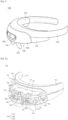
- FIG. 1 is a perspective view of the electronic device 100, according to an embodiment.
- the electronic device 100 includes the housing 110, a front cover 150 coupled to the front portion of the housing 110, the image output module 120 provided inside the housing 110, a semi-transparent member 122 exposed under the housing 110, and the wearing member 170 extending towards the rear portion of the housing 110.
- the housing 110 may have a substrate, electronic parts for implementing various functions of the electronic device 100, the camera module 130, and the image output module 120 provided therein.
- the housing 110 may protect various electronic parts provided therein.
- the front cover 150 may be coupled to the front portion of the housing 110.
- the wearing member 170 extending rearward from opposite ends of the housing 110 may be coupled to the rear portion of the housing 110.
- the semi-transparent member 122 may be exposed under the housing 110.
- the wearing member 170 may have a shape corresponding to the head of the user to surround at least a portion of the head of the user.
- the wearing member 170 may extend rearward from opposite ends of the housing 110.
- the wearing member 170 may be formed of a material having elasticity to be put on the heads of various users. Additionally, the wearing member 170 may include elastic straps.
- the wearing member 170 may include a seating member 172 disposed on at least a portion of the forehead or the user's face.
- the seating member 172 may be formed on the inner side (i.e., the rear portion) of the wearing member 170 along the lengthwise direction of the wearing member 170.
- the seating member 172 may be formed of one or more cushion materials, such as a sponge or fabric, to provide a comfortable fit when in contact with the user's face.
- the seating member 172 may be detachably attached to the wearing member 170.
- the front cover 150 may be coupled to the front portion of the housing 110, and may have one or more openings 151 formed therein.
- the camera module 130 in the housing 110 may be arranged while facing forward to take an image of an object or a target positioned in front of the camera module 130 through the opening of the front cover 150.
- the camera module 130 may be disposed at a specified angle with respect to the front direction.
- the front cover 150 may have a camera area 153 surrounding the openings.
- the camera area 153 may be formed around one or more openings of the front cover 150.
- the camera area 153 may include a groove surrounding one or more openings.
- the semi-transparent member 122 may be disposed to be exposed under the housing 110.
- the semi-transparent member 122 may be disposed to be facing the eyeballs of the user.
- the semi-transparent member 122 may be formed as an integrated module with the image output module 120, however the present disclosure is not limited thereto.
- the semi-transparent member 122 may be coupled to the image output module 120 under the housing 110, while serving as a module separate from the image output module 120.
- the semi-transparent member 122 may be disposed under the image output module 120.
- the semi-transparent member 122 includes at least one semi-transparent lens and may include a transparent lens. The user may look ahead through the semi-transparent member 122. The user may view the content output by the image output module 120 through the semi-transparent member 122.
- the visual information transmitted to the eyeball of the user may include visual information transmitted through the semi-transparent member 122 and visual information transmitted through reflection and/or refraction from the semi-transparent member 122.
- the visual information transmitted through the semi-transparent member 122 may be visual information related to the front of the user, and the visual information that is refracted and/or reflected by the semi-transparent member 122 may be displayed by the image output module 120.
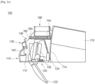
- FIG. 2a is a view illustrating the inner part of the housing 110 of the electronic device 100, according to an embodiment.
- FIG. 2b is a view illustrating the inner part of the housing 110 of the electronic device 100, according to an embodiment.
- FIG. 2c is a cross-sectional view taken along line A-A' of FIG. 2b illustrating the housing 110 of the electronic device 100, according to an embodiment.
- the housing 110 includes the bracket 140, the substrate, the camera module 130, and the image output module 120.
- the housing 110 may have various shapes to include a plurality of electronic parts provided therein.
- the housing 110 may have a front portion and/or an upper portion that may be open.
- the front cover 150 described above may be coupled to the open front portion of the housing 110 or may be formed on a front surface of the housing 110.
- the housing 110 is open at the front portion thereof and may include an upper surface, a lower surface 112, and a rear surface 114 formed between the upper surface and the lower surface 112. Alternatively, the housing 110 may include a front surface.
- the housing includes the lower surface 112 and the rear surface 114.
- the housing 110 may have various shapes and may include an upper surface, a lower surface facing the upper surface, and a front surface and a rear surface interposed between the upper surface and the lower surface and connecting the upper surface with the lower surface.
- an opening may be formed in one or more surfaces of the housing 110.
- the housing may include a frame and a cover.
- Various electrical elements, parts, and modules e.g., the camera module 130 or the image output module 120, etc.
- the cover e.g., an upper cover 160 and/or a front cover 150 of FIG. 3
- the cover is coupled to the frame and may protect various electrical elements, parts, and modules disposed in the frame from an external impact.
- the bracket 140 is disposed inside the housing 110.
- the bracket 140 may include a first surface 142 facing forward and a second surface 144 facing upward.
- the second surface 144 may extend rearward from the upper end of the first surface 142.
- the second surface 144 may extend from the upper end of the first surface 142 to the rear surface 114.
- the front end of the second surface 144 may be connected to the upper end of the first surface 142 and the rear end of the second surface 144 may be connected to the rear surface 114.
- the first surface 142 may be disposed perpendicularly to the lower surface 112.
- the second surface 144 may be disposed in parallel to the lower surface 112.
- the first surface 142 and the second surface 144 may be connected perpendicularly to each other.
- the bracket 140 may be in a substantially inversed L shape.
- the drawings illustrate that the lower surface 112 of the housing 110 and the first surface 142 of the bracket 140 are connected perpendicularly to each other, and the lower surface 112 of the housing 110 and the second surface 144 of the bracket 140 are connected to each other in parallel, this is provided for the illustrative purposes. That is, the bracket 140 and the housing 110 are not limited to the form, position, structure, or shape illustrated in the drawings.
- the second surface 144 may be interposed between the lower surface 112 and the upper cover 160, the front end of the second surface 144 may be connected to the first surface 142, and the rear end of the second surface 144 may be connected to the rear surface 114.
- the second surface 144 of the bracket 140 has a shape corresponding to the rear surface 114, which may correspond to the front surface of the front cover 150 or the housing 110.
- the front portion of the second surface 144 of the bracket 140 may have a shape corresponding to the front portion of the lower surface 112.
- the bracket 140 may be formed in a substantially inversed L shape.
- the camera module 130 may be disposed on the first surface 142 of the bracket 140.
- the substrate may be disposed on the second surface 144 of the bracket 140.
- the image output module 120 may be interposed between the first surface 142 of the bracket 140 and the rear surface 114 of the housing 110.
- the camera module 130 may include at least one camera device.
- the camera module 130 may include a plurality of camera modules 1301, 1302, and 1303.
- the plurality of camera modules 1301, 1302, and 1303 may be disposed on the first surface 142 of the bracket 140 to face forward.
- the plurality of camera modules 1301, 1302, and 1303 may be arranged at a specified angle with respect to the front-surface direction.
- the image output module 120 may be disposed under the second surface 144 of the bracket 140. A portion of the image output module 120 may be interposed between the second surface 144 of the bracket 140 and the lower surface 112 of the housing 110. The remaining portion of the image output module 120 may be exposed under the lower surface 112 of the housing 110.
- the image output module 120 may include a light output member 124, a light transmitting member 126, and includes a semi transparent member 122 that includes at least one semi-transparent lens.
- the light output member 124 may include a display device or a projector device.
- the light output member 124 may be positioned at a rear portion of the image output module 120 as illustrated in FIG. 2c .
- the light transmitting member 126 optically connects the light output member 124 and the semi-transparent member 122 positioned facing the eyeballs of the user, thereby transmitting light output from the light output member 124 to the semi-transparent member 122.
- the light output member 124 may include, for example, various light output devices that output light, such as a display or a projector.
- the light transmitting member 126 may be disposed to face the light output member 124 and may include a mirror that reflects the light output from the light output member 124.
- the light transmitting member 126 illustrated in FIG. 2c is provided for illustrative purposes and may further include one or more mirrors and/or lenses.
- the light transmitting member 126 may include at least one lens and/or mirror that reflects and/or refracts visual information output from the light output member 124 to the semi-transparent member 122.
- the semi-transparent member 122 may be disposed at a position facing the eyeballs of the user when the user puts on the electronic device 100.
- the semi-transparent member 122 may be disposed under the lower surface 112 of the housing 110.
- the semi-transparent member 122 includes a semi-transparent lens that may a specified transmittance and a specified reflectance. As a level of the transmittance of the semi-transparent lens increases, an amount of external light transmitted to the eyeballs through the semi-transparent lens increases. As a level of reflectance of the semi-transparent lens increases, an amount of light of an image output from the light output member 124 and transmitted to the eyeballs of the user increases.
- the image output module 120 is disposed in the internal space defined by the bracket 140, the rear surface 114, and the lower surface 112.
- the semi-transparent member 122 may be disposed under the internal space. As described above, the semi-transparent member 122 may be integrated with the image output module 120 or may be coupled to the image output module 120 and/or the housing 110 while serving as a separate component.
- the electronic device 100 may include a connection unit 131 that electrically connects the camera module 130 or the image output module 120 with the substrate.
- the connection unit 131 may include various functional modules including an image processing module and/or a transmission/reception module and a conductive signal line for transmitting a signal.
- the conductive signal line may be made of a material including a metal.
- the conductive signal line may be disposed on the first surface 142 or the second surface 144 of the bracket 140.
- the substrate may be disposed on the second surface 144 of the bracket 140.
- the substrate may include a first substrate 182 disposed on the second surface 144 and a second substrate 184 disposed on the first substrate 182.
- the substrate may be interposed between the second surface 144 of the bracket 140 and the upper cover 160.
- a battery 186 may be disposed on the second substrate 184.
- the battery 186 may be disposed on the side surface of the wearing member 170.
- the battery 186 is disposed at an upper portion of the electronic device 100, and when the user puts on the electronic device 100, the battery 186 may be disposed at a position corresponding to the forehead of the user.
- the burden of the weight of the battery 186 may be reduced as compared to the case in which the battery 186 is disposed at the lower portion of the electronic device 100.
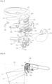
- FIG. 3 is an exploded perspective view of the electronic device 100, according to an embodiment.
- a mounting groove 141 is formed in the first surface 142 of the bracket 140 such that the mounting of at least one camera module 130 may be provided.
- the mounting groove 141 may have a shape corresponding to the shape of the camera module 130.
- the first camera module 1301 may be disposed at the center of the first surface 142 and the second camera module 1302 and the third camera module 1303 may be disposed at opposite sides of the first camera module 1301.
- the second surface 144 of the bracket 140 may have one or more openings. The whole weight of the bracket 140 and the electronic device 100 may be reduced and supported by the opening. One or more openings may be formed in the second surface 144 of the bracket 140, and a connection unit for electrical connection between other electrical parts may be positioned through the opening. The substrate and the battery 186 may be interposed between the second surface 144 of the bracket 140 and the upper cover 160.
- One or more openings 113 may be formed in the lower surface 112 of the housing 110. At least a portion of the image output module 120 may be disposed in the opening 113. A portion of the image output module 120 may be disposed inside the housing 110. A portion of the image output module 120 may be interposed between the opening 113 and the second surface 144 of the bracket 140. The remaining portion of the image output module 120 may extend to the lower portion of the housing 110 from the inside of the housing 110 through the opening 113. At least a portion of the semi-transparent member 122 may be connected with the image output module 120 through the opening 113 and may be exposed under the housing 110.
- the image output module 120 may be included in an integral module including the semi-transparent member 122 facing the eyeballs of the user.
- the semi-transparent member 122 may be disposed under the housing 110 through the opening 113 in the lower surface 112 of the housing 110.
- One or more openings 113 may be formed in the lower surface 112 of the housing 110.
- the image (or light) generated from the image output module 120 may be transmitted to the semi-transparent member 122 positioned under the housing 110 through the opening 113.
- the image (or light) output from the light output member 124 of the image output module 120 may be transmitted to the semi-transparent member 122 through at least one light transmitting member 126.
- the light transmitting member 126 may include one or more mirrors or lenses. The number, type or arrangement angle of the light transmitting members 126 may vary depending on an optical path inside the image output module 120.
- One or more openings may be formed in the housing 110 or the upper cover 160 to discharge heat generated from the substrate and the battery 186.
- the heat may be easily discharged through the opening and the internal temperature of the housing 110 may be lowered to prevent the performance of the electronic device 100 from being deteriorated.
- the front cover 150 may be coupled to the housing 110 in a physical manner such as a manner using a hook or a magnet, or in an electromagnet manner.
- the front cover 150 may be coupled to the housing 110 by an adhesive member provided between the front cover 150 and the housing 110.
- the front cover 150 may be a streamlined curved surface corresponding to that of the lower surface 112 of the housing 110.
- the front cover 150 may have an opening 151 formed therein such that external light may reach the camera module 130.
- the front cover 150 may further include the camera module 130.
- the camera module 130 may be provided in the opening 151.
- At least one or more openings 151 may be formed to correspond to a number equal to the number of camera modules 130.
- the camera area 153 may be formed around the one or more openings 151 of the front cover 150.
- the camera area 153 may be provided in the form of a groove surrounding one or more openings 151.
- the opening 151 may be positioned inside the groove, thereby preventing the camera module 130 exposed through the opening 151 from being damaged.
- the front cover 150 may further include a window 152 to constitute the surface of the electronic device 100.
- the window 152 may include a variety of materials, various patterns, and/or various colors to enhance the aesthetics of the electronic device 100.
- the window 152 may protect the camera module 130 exposed through the opening 151 of the front cover 150. External light may be transmitted to the camera lens of the camera module 130 through the window 152.
- the window 152 may block a portion of light incident from the outside.
- the window 152 may include at least one of plastic, ceramic, or glass.
- the plastic may include polycarbonate and/or acrylic; and the ceramic may include glass, sapphire and/or transparent ceramics.
- the window 152 may include various materials and may have various transmittances. The output of the light output member 124 of the image output module 120 may be reduced by adjusting the transmittance of the window 152 to block a portion of light incident from the outside.
- the window 152 may cover the surface of the front cover 150 in which the camera module 130 is disposed. Further, the window 152 may extend further downward from the surface of the front cover 150 and may be disposed in front of the semi-transparent member 122. The amount of external light incident to the semi-transparent member 122 may be adjusted depending on the transmittance of the window 152.
- the window 152 may include a first area provided in front of the camera module 130 and a second area provided in front of the semi-transparent member 122.
- the first area may have a first transmittance and the second area may have a second transmittance different from the first transmittance.
- the first transmittance and the second transmittance may be adjusted such that the first area may adjust an amount of light incident to the camera module 130 and the second area may adjust an amount of light incident to the semi-transparent member 122.
- the window 152 may be disposed in front of the semi-transparent member 122 without covering the camera module 130. In this case, the window 152 may block a portion of external light incident to the semi-transparent member 122.
- the electronic device 100 may include a connector module 194 that is able to communicate with an external electronic device, a speaker module 197 that is able to reproduce a sound signal, a microphone module 198 which is able to convert a voice signal of the user into an electrical signal, a touch pad module 192 which allows touch input by a user, and a proximity sensor 196 to measure a distance or a depth.
- a connector module 194 that is able to communicate with an external electronic device
- a speaker module 197 that is able to reproduce a sound signal
- a microphone module 198 which is able to convert a voice signal of the user into an electrical signal
- a touch pad module 192 which allows touch input by a user
- a proximity sensor 196 to measure a distance or a depth.
- the connector module 194 and the touch pad module 192 may be disposed on a first side surface of the housing 110.
- the connector module 194 may include a universal serial bus (USB) module including a USB interface.
- USB universal serial bus
- the connector module 194 may be connected to the external electronic device through the USB module, and may transmit the touch input by the user to the external electronic device.
- the touch pad module 192 may receive the touch input by the user (e.g., direct touch input or hovering input).
- FIG. 4 is a view illustrating the field of view of the camera module 130 of the electronic device 200 and the field of view of a user, according to an embodiment.
- FIG. 5 is a view illustrating the field of view of the camera module 130 of the electronic device 200 and the field of view of the user, according to an embodiment.
- the field of view 201 of the camera module 130 of the electronic device 200 may include the field of view 202 of the user through the semi-transparent member 122.
- the triangles drawn by dotted lines in the drawing are the field of view of each camera and the field of view 202 of the user, respectively, and straight lines A and B are centerlines of the field of view of the camera and the field of view 202 of the user.
- the field of view of the user may face downward from the front direction.
- the field of view 201 of the camera module 130 may cover the field of view 202 of the user.
- the centerline of the field of view 202 of the user and the centerline of the field of view 201 of the camera module 130 may face downward from the front direction.
- the camera module 130 and the semi-transparent member 122 may be arranged such that the centerline of the field of view 202 of the user is parallel to the centerline of the field of view 201 of the camera module 130.
- the camera module 130 and the semi-transparent member 122 are arranged such that the centerline of the field of view 201 of the camera module 130 faces downward from the centerline of the field of view 202 of the user.
- the centerline of the field of view 201 of the camera module 130 and the centerline of the field of view 202 of the user may cross each other ahead.
- the electronic device 200 may recognize an object positioned in the field of view 201 of the camera module 130, and may output, in the form of visual information, information on the recognized object through the light output member 124, and may provide the output visual information for a user through the semi-transparent member 122 via the light transmitting member 126 including at least one lens and/or mirror.
- the external light reflected from an object positioned in the field of view 201 of the camera module 130 may be incident to the camera module 130 through the opening 151 or the window 152 formed in the front cover 150.
- the window 152 may be formed of a plastic material and may be manufactured to have a specified transmittance in a dual-injection molding manner.
- the user may view an object positioned forward through the semi-transparent member 122.
- the semi-transparent member 122 includes a semi-transparent lens. That is, the user may receive first visual information associated with the external environment ahead and second visual information associated with the first visual information.
- the first visual information may be transmitted to the eyeball through the semi-transparent lens and associated with an environment in front of the user, which is within the field of view of the user, and the second visual information may be view information output from the image output module 120.
- the second visual information may include additional visual information obtained by editing or processing the first visual information within the field of view, which is obtained by the camera module 130.
- the field of view 201 of the camera module 130 covers the field of view 202 of the user. Accordingly, the electronic device 200 may recognize all objects positioned within the field of view 202 of the user and may visually provide additional information about the objects for the user.
- Reference signs L1 and L2 illustrated in FIGS. 4 and 5 refer to the minimum distance at which the field of view 201 of the camera module 130 may cover the field of view 102 of the user according to the embodiments.
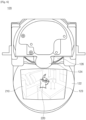
- FIG. 6 illustrates the image output module 120 and the semi-transparent member 122 of the electronic device, according to an embodiment.
- FIG. 7 is a view illustrating transmitting visual information output from the light output member 124 to the eyeballs of the user, according to an embodiment.
- the image output from the light output member 124 of the image output module 120 may be transmitted to the semi-transparent member 122.
- the image output module 120 may include the light transmitting member 126 that includes one or more lenses and/or mirrors. The one or more lenses and/or mirrors may optically connect the light output member 124 with the semi-transparent member 122.
- the front surface of the semi-transparent member 122 may be formed to be in a convex shape.
- the rear surface 114 of the semi-transparent member 122, facing the eyeballs of the user may be formed to be in a concave shape.
- the semi-transparent member 122 may have semi-transparency and includes a semi-transparent lens.
- the light output member 124 may include a light generating device, such as a display device or a projector, which emits light.
- the second visual information 220 output from the light output member 124 is reflected by the semi-transparent member 122 and may be transmitted to the eyeballs of the user.
- the first visual information 210 transmitted through external light may be transmitted to the eyeballs of the user through the semi-transparent member 122.
- An image area 123 in which the first visual information 210 and the second visual information 220, which are transmitted to the eyeball of the user, may be formed as illustrated in FIG. 6 . Since the lower portion of the semi-transparent member 122 is disposed closer to the eyeball of the user than the upper portion of the semi-transparent member 122, the upper portion of the image area 123 may be formed to be wider than the lower portion of the image area 123.
- the camera module 130 is arranged to be inclined at a first angle with respect to a vertical line, and the upper and lower portions of the opening 151 formed in the front surface of the housing 110 or the front cover 150 may be asymmetrically formed.
- the lower portion of the opening 151 may be formed to be deeper than the upper portion of the opening 151, and the lower inner sidewall of the opening 151 may be formed in an inclined manner so as not to block the field of view of the camera module 130.
- the semi-transparent member 122 is arranged to be inclined at a second angle with respect to the vertical line.
- the second angle is formed to be greater than the first angle.
- the semi-transparent member 122 facing the eyeball of the user of the electronic device 100 is positioned under the eyeballs of the user such that the field of view of the user corresponds to the main field of view of a human being.
- the semi-transparent member 122 is arranged to be inclined at a specified angle with respect to the line perpendicular to the front direction.
- FIG. 8 is a block diagram illustrating an electronic device 801 in a network environment 800 according to various embodiments.
- the electronic device 801 in the network environment 800 may communicate with an electronic device 802 via a first network 898 (e.g., a short-range wireless communication network), or an electronic device 804 or a server 808 via a second network 899 (e.g., a long-range wireless communication network).
- the electronic device 801 may communicate with the electronic device 804 via the server 808.
- the electronic device 801 may include a processor 820, memory 830, an input device 850, a sound output device 855, a display device 860, an audio module 870, a sensor module 876, an interface 877, a haptic module 879, a camera module 880, a power management module 888, a battery 889, a communication module 890, a subscriber identification module (SIM) 896, or an antenna module 897.
- at least one (e.g., the display device 860 or the camera module 880) of the components may be omitted from the electronic device 801, or one or more other components may be added in the electronic device 801.
- some of the components may be implemented as single integrated circuitry.
- the sensor module 876 e.g., a fingerprint sensor, an iris sensor, or an illuminance sensor
- the display device 860 e.g., a display
- an audio module 870 e.g., a microphone
- a sensor module 876 e.g
- the processor 820 may execute, for example, software (e.g., a program 840) to control at least one other component (e.g., a hardware or software component) of the electronic device 801 coupled with the processor 820, and may perform various data processing or computation. According to one embodiment, as at least part of the data processing or computation, the processor 820 may load a command or data received from another component (e.g., the sensor module 876 or the communication module 890) in volatile memory 832, process the command or the data stored in the volatile memory 832, and store resulting data in non-volatile memory 834.
- software e.g., a program 840
- the processor 820 may load a command or data received from another component (e.g., the sensor module 876 or the communication module 890) in volatile memory 832, process the command or the data stored in the volatile memory 832, and store resulting data in non-volatile memory 834.
- the processor 820 may include a main processor 821 (e.g., a central processing unit (CPU) or an application processor (AP)), and an auxiliary processor 823 (e.g., a graphics processing unit (GPU), an image signal processor (ISP), a sensor hub processor, or a communication processor (CP)) that is operable independently from, or in conjunction with, the main processor 821.
- auxiliary processor 823 may be adapted to consume less power than the main processor 821, or to be specified to a specified function.
- the auxiliary processor 823 may be implemented as separate from, or as part of the main processor 821.
- the auxiliary processor 823 may control at least some of functions or states related to at least one component (e.g., the display device 860, the sensor module 876, or the communication module 890) among the components of the electronic device 801, instead of the main processor 821 while the main processor 821 is in an inactive (e.g., sleep) state, or together with the main processor 821 while the main processor 821 is in an active state (e.g., executing an application).
- the auxiliary processor 823 e.g., an image signal processor or a communication processor
- the memory 830 may store various data used by at least one component (e.g., the processor 820 or the sensor module 876) of the electronic device 801.
- the various data may include, for example, software (e.g., the program 840) and input data or output data for a command related thereto.
- the memory 830 may include the volatile memory 832 or the non-volatile memory 834.
- the program 840 may be stored in the memory 830 as software, and may include, for example, an operating system (OS) 842, middleware 844, or an application 846.
- OS operating system
- middleware middleware
- application 846 application
- the input device 850 may receive a command or data to be used by other component (e.g., the processor 820) of the electronic device 801, from the outside (e.g., a user) of the electronic device 801.
- the input device 850 may include, for example, a microphone, a mouse, a keyboard, or a digital pen (e.g., a stylus pen).
- the sound output device 855 may output sound signals to the outside of the electronic device 801.
- the sound output device 855 may include, for example, a speaker or a receiver.
- the speaker may be used for general purposes, such as playing multimedia or playing record, and the receiver may be used for an incoming calls. According to an embodiment, the receiver may be implemented as separate from, or as part of the speaker.
- the display device 860 may visually provide information to the outside (e.g., a user) of the electronic device 801.
- the display device 860 may include, for example, a display, a hologram device, or a projector and control circuitry to control a corresponding one of the display, hologram device, and projector.
- the display device 860 may include touch circuitry adapted to detect a touch, or sensor circuitry (e.g., a pressure sensor) adapted to measure the intensity of force incurred by the touch.
- the audio module 870 may convert a sound into an electrical signal and vice versa. According to an embodiment, the audio module 870 may obtain the sound via the input device 850, or output the sound via the sound output device 855 or a headphone of an external electronic device (e.g., an electronic device 802) directly (e.g., wiredly) or wirelessly coupled with the electronic device 801.
- an external electronic device e.g., an electronic device 802 directly (e.g., wiredly) or wirelessly coupled with the electronic device 801.
- the sensor module 876 may detect an operational state (e.g., power or temperature) of the electronic device 801 or an environmental state (e.g., a state of a user) external to the electronic device 801, and then generate an electrical signal or data value corresponding to the detected state.
- the sensor module 876 may include, for example, a gesture sensor, a gyro sensor, an atmospheric pressure sensor, a magnetic sensor, an acceleration sensor, a grip sensor, a proximity sensor, a color sensor, an infrared (IR) sensor, a biometric sensor, a temperature sensor, a humidity sensor, or an illuminance sensor.
- the interface 877 may support one or more specified protocols to be used for the electronic device 801 to be coupled with the external electronic device (e.g., the electronic device 802) directly (e.g., wiredly) or wirelessly.
- the interface 877 may include, for example, a high definition multimedia interface (HDMI), a universal serial bus (USB) interface, a secure digital (SD) card interface, or an audio interface.
- HDMI high definition multimedia interface
- USB universal serial bus
- SD secure digital
- a connecting terminal 878 may include a connector via which the electronic device 801 may be physically connected with the external electronic device (e.g., the electronic device 802).
- the connecting terminal 878 may include, for example, a HDMI connector, a USB connector, a SD card connector, or an audio connector (e.g., a headphone connector).
- the haptic module 879 may convert an electrical signal into a mechanical stimulus (e.g., a vibration or a movement) or electrical stimulus which may be recognized by a user via his tactile sensation or kinesthetic sensation.
- the haptic module 879 may include, for example, a motor, a piezoelectric element, or an electric stimulator.
- the camera module 880 may capture a still image or moving images.
- the camera module 880 may include one or more lenses, image sensors, image signal processors, or flashes.
- the power management module 888 may manage power supplied to the electronic device 801. According to one embodiment, the power management module 888 may be implemented as at least part of, for example, a power management integrated circuit (PMIC).
- PMIC power management integrated circuit
- the battery 889 may supply power to at least one component of the electronic device 801.
- the battery 889 may include, for example, a primary cell which is not rechargeable, a secondary cell which is rechargeable, or a fuel cell.
- the communication module 890 may support establishing a direct (e.g., wired) communication channel or a wireless communication channel between the electronic device 801 and the external electronic device (e.g., the electronic device 802, the electronic device 804, or the server 808) and performing communication via the established communication channel.
- the communication module 890 may include one or more communication processors that are operable independently from the processor 820 (e.g., the application processor (AP)) and supports a direct (e.g., wired) communication or a wireless communication.
- AP application processor
- the communication module 890 may include a wireless communication module 892 (e.g., a cellular communication module, a short-range wireless communication module, or a global navigation satellite system (GNSS) communication module) or a wired communication module 894 (e.g., a local area network (LAN) communication module or a power line communication (PLC) module).
- a wireless communication module 892 e.g., a cellular communication module, a short-range wireless communication module, or a global navigation satellite system (GNSS) communication module
- GNSS global navigation satellite system
- wired communication module 894 e.g., a local area network (LAN) communication module or a power line communication (PLC) module.
- LAN local area network
- PLC power line communication
- a corresponding one of these communication modules may communicate with the external electronic device via the first network 898 (e.g., a short-range communication network, such as Bluetooth TM , wireless-fidelity (Wi-Fi) direct, or infrared data association (IrDA)) or the second network 899 (e.g., a long-range communication network, such as a cellular network, the Internet, or a computer network (e.g., LAN or wide area network (WAN)).
- the first network 898 e.g., a short-range communication network, such as Bluetooth TM , wireless-fidelity (Wi-Fi) direct, or infrared data association (IrDA)
- the second network 899 e.g., a long-range communication network, such as a cellular network, the Internet, or a computer network (e.g., LAN or wide area network (WAN)
- These various types of communication modules may be implemented as a single component (e.g., a single chip), or may be implemented as multi
- the wireless communication module 892 may identify and authenticate the electronic device 801 in a communication network, such as the first network 898 or the second network 899, using subscriber information (e.g., international mobile subscriber identity (IMSI)) stored in the subscriber identification module 896.
- subscriber information e.g., international mobile subscriber identity (IMSI)
- the antenna module 897 may transmit or receive a signal or power to or from the outside (e.g., the external electronic device) of the electronic device 801.
- the antenna module 897 may include an antenna including a radiating element composed of a conductive material or a conductive pattern formed in or on a substrate (e.g., PCB).
- the antenna module 897 may include a plurality of antennas. In such a case, at least one antenna appropriate for a communication scheme used in the communication network, such as the first network 898 or the second network 899, may be selected, for example, by the communication module 890 (e.g., the wireless communication module 892) from the plurality of antennas.
- the signal or the power may then be transmitted or received between the communication module 890 and the external electronic device via the selected at least one antenna.
- another component e.g., a radio frequency integrated circuit (RFIC)
- RFIC radio frequency integrated circuit
- At least some of the above-described components may be coupled mutually and communicate signals (e.g., commands or data) therebetween via an inter-peripheral communication scheme (e.g., a bus, general purpose input and output (GPIO), serial peripheral interface (SPI), or mobile industry processor interface (MIPI)).
- an inter-peripheral communication scheme e.g., a bus, general purpose input and output (GPIO), serial peripheral interface (SPI), or mobile industry processor interface (MIPI)
- commands or data may be transmitted or received between the electronic device 801 and the external electronic device 804 via the server 808 coupled with the second network 899.
- Each of the electronic devices 802 and 804 may be a device of a same type as, or a different type, from the electronic device 801.
- all or some of operations to be executed at the electronic device 801 may be executed at one or more of the external electronic devices 802, 804, or 808.
- the electronic device 801 instead of, or in addition to, executing the function or the service, may request the one or more external electronic devices to perform at least part of the function or the service.
- the one or more external electronic devices receiving the request may perform the at least part of the function or the service requested, or an additional function or an additional service related to the request, and transfer an outcome of the performing to the electronic device 801.
- the electronic device 801 may provide the outcome, with or without further processing of the outcome, as at least part of a reply to the request.
- a cloud computing, distributed computing, or client-server computing technology may be used, for example.
- the electronic device may be one of various types of electronic devices.
- the electronic devices may include, for example, a portable communication device (e.g., a smartphone), a computer device, a portable multimedia device, a portable medical device, a camera, a wearable device, or a home appliance. According to an embodiment of the disclosure, the electronic devices are not limited to those described above.
- each of such phrases as “A or B,” “at least one of A and B,” “at least one of A or B,” “A, B, or C,” “at least one of A, B, and C,” and “at least one of A, B, or C,” may include any one of, or all possible combinations of the items enumerated together in a corresponding one of the phrases.
- such terms as “1st” and “2nd,” or “first” and “second” may be used to simply distinguish a corresponding component from another, and does not limit the components in other aspect (e.g., importance or order).
- an element e.g., a first element
- the element may be coupled with the other element directly (e.g., wiredly), wirelessly, or via a third element.
- module may include a unit implemented in hardware, software, or firmware, and may interchangeably be used with other terms, for example, “logic,” “logic block,” “part,” or “circuitry”.
- a module may be a single integral component, or a minimum unit or part thereof, adapted to perform one or more functions.
- the module may be implemented in a form of an application-specific integrated circuit (ASIC).
- ASIC application-specific integrated circuit
- Various embodiments as set forth herein may be implemented as software (e.g., the program 840) including one or more instructions that are stored in a storage medium (e.g., internal memory 836 or external memory 838) that is readable by a machine (e.g., the electronic device 801).
- a processor(e.g., the processor 820) of the machine e.g., the electronic device 801 may invoke at least one of the one or more instructions stored in the storage medium, and execute it, with or without using one or more other components under the control of the processor. This allows the machine to be operated to perform at least one function according to the at least one instruction invoked.
- the one or more instructions may include a code generated by a complier or a code executable by an interpreter.
- the machine-readable storage medium may be provided in the form of a non-transitory storage medium.
- non-transitory simply means that the storage medium is a tangible device, and does not include a signal (e.g., an electromagnetic wave), but this term does not differentiate between where data is semi-permanently stored in the storage medium and where the data is temporarily stored in the storage medium.
- a method may be included and provided in a computer program product.
- the computer program product may be traded as a product between a seller and a buyer.
- the computer program product may be distributed in the form of a machine-readable storage medium (e.g., compact disc read only memory (CD-ROM)), or be distributed (e.g., downloaded or uploaded) online via an application store (e.g., PlayStore TM ), or between two user devices (e.g., smart phones) directly. If distributed online, at least part of the computer program product may be temporarily generated or at least temporarily stored in the machine-readable storage medium, such as memory of the manufacturer's server, a server of the application store, or a relay server.
- CD-ROM compact disc read only memory
- an application store e.g., PlayStore TM
- two user devices e.g., smart phones
- each component e.g., a module or a program of the above-described components may include a single entity or multiple entities. According to various embodiments, one or more of the above-described components may be omitted, or one or more other components may be added. Alternatively or additionally, a plurality of components (e.g., modules or programs) may be integrated into a single component. In such a case, according to various embodiments, the integrated component may still perform one or more functions of each of the plurality of components in the same or similar manner as they are performed by a corresponding one of the plurality of components before the integration.
- operations performed by the module, the program, or another component may be carried out sequentially, in parallel, repeatedly, or heuristically, or one or more of the operations may be executed in a different order or omitted, or one or more other operations may be added.
- an aspect of the present disclosure is to provide an electronic device in which the weight felt by a user can be reduced when the user puts on the electronic device.
- Another aspect of the present disclosure is to provide an electronic device, in which the field of view of a camera module of the electronic device can cover the whole field of view of a user.
- Another aspect of the present disclosure is to provide an electronic device capable of allowing the field of view of a user to correspond to the main field of view of a human being.
- the load of the electronic device can be concentrated on a partial area of the electronic device supported by a part of a user's body, so the weight felt by the user may be reduced.
- the field of view of the camera module covers the whole field of view of the user, all objects positioned within the field of view of the user can be recognized.
Landscapes
- Physics & Mathematics (AREA)
- General Physics & Mathematics (AREA)
- Optics & Photonics (AREA)
- Studio Devices (AREA)
Description
- The present disclosure relates generally to a head-mounted electronic device, and more particularly, to an electronic device including a semi-transparent member, which is disposed under an image output module at a specified angle with respect to a direction of outputting an image.
- Recently, various electronic devices, which are able to be directly put on a human body, have been developed. These electronic devices are generally called "wearable devices".
- The wearable device put on a part of the human body may include, for example, a head-mounted display (HMD) put on the head of a user to display an image, smart-glasses, a smart watch (wristband), a contact lens-type device, a ring-type device, a shoe-type device, a clothing-type device, and a glove-type device, and may have various types attachable to a part of the human body or clothes. In particular, the HMD may be provided as goggles or glasses.
- As the wearable device is directly put on the human body, the mobility and the accessibility of the user may be improved.
-
CN-206497255-U discloses an augmented reality display system, including a wear frame, a display module, two perspective type leaded light components and mainboard. The the user can see the true scene in the external world mixed with a 3D virtual scene. -
WO-2017/100074-A1 discloses a head worn computer including an optical chassis with a rigid open box structure configured to provide a stable optical mounting reference plane and a plurality of image source reference planes. The head worn computer further includes a first image source mounted on one of the image source reference planes to project first image light through a first hole in the optical mounting reference plane and a second image source mounted on a second of the image source reference planes and configured to project second image light through a second hole in the optical mounting reference plane. An outer frame holds the optical chassis such that, when worn by a user, the first and second image light is aligned with the eyes of the user. -
WO-97/34182-A1 -
CN-104898276-A discloses a head-mounted display device, which comprises a shell and a group of optical system arranged in the shell. The optical system comprises an image display screen, an optical magnifying lens group and a reflecting and transmitting lens, wherein the image display screen is located above the optical magnifying lens group; and the reflecting and transmitting lens is located below the optical magnifying lens group. The optical path of the optical system is that image optical information emitted by the image display screen is transmitted via the optical magnifying lens group and then reflected to a human eye by the reflecting and transmitting lens; and the environment optical information outside the head-mounted display device is transmitted to the human eye via the reflecting and transmitting lens. -
US-2016/282628-A1 discloses a method and apparatus of displaying an electronic video image using a head-worn near-to-eye display in a non-immersive fashion, such that the wearer can choose, through simple adjustments of their neck and eye angles, to either look at the displayed video image or their natural environment. Prescription lenses may be incorporated into the optical chain of the near-to-eye display. Motion and position sensors incorporated into the head-worn device are used to automatic stabilization of the video image and to automatically adjust the vertical angle of either the camera or the electronic display or both, by sensing the vertical angular position of the user's head. -
US-2013/120224-A1 discloses techniques for recalibration of outward facing cameras supported by a see-through, head mounted, mixed reality display system having a flexible portion between see-through displays for the eyes. Each outward facing camera has a fixed spatial relationship with a respective or corresponding see-through display positioned to be seen through by a respective eye. For front facing cameras, the fixed spatial relationship allows a predetermined mapping between positions on an image sensor of each camera and positions on the respective display. The mapping may be used to register a position of a virtual object to a position of a real object. A change in a first flexible spatial relationship between the outward facing cameras can be automatically detected. A second spatial relationship between the cameras is determined. A registration of a virtual object to a real object may be updated based on the second spatial relationship. -
US-9721928-B1 - According to an embodiment, an aspect of the present disclosure is to provide an electronic device in which the weight felt by a user can be reduced when the user puts on the electronic device.
- Another aspect of the present disclosure is to provide an electronic device, in which the field of view of a camera module of the electronic device can cover the whole field of view of a user.
- Another aspect of the present disclosure is to provide an electronic device capable of allowing the field of view of a user to correspond to the main field of view of a human being.
- The present disclosure has been made to address the above-mentioned problems and disadvantages, and to provide at least the advantages described below.
- In accordance with an aspect of the present disclosure, an electronic device is that includes a housing including a front surface and a lower surface, the front surface having a first opening and the lower surface having a second opening, a bracket disposed inside the housing, a camera that obtains an image of an external object through the first opening and is disposed on a first surface of the bracket, an image output module that outputs an image to an outside through the second opening and is disposed on a second surface of the bracket, a circuit board electrically connected with the camera and the image output module and disposed on a third surface of the bracket, and a semi-transparent member includes at least one semi-transparent lens disposed under the image output module, at a specified angle with respect to a direction of outputting the image such that the image is displayed for a user; wherein the camera is disposed to be inclined at a first angle with respect to a line perpendicular to a direction that the front surface faces, and the semi-transparent lens is disposed to be inclined at a second angle, which is greater than the first angle, with respect to the perpendicular line.
- In accordance with an aspect of the present disclosure, an electronic device, which is configured to be put on the head of a user, includes a housing including an upper surface, a lower surface including an opening, a rear surface, which is interposed between the upper surface and the lower surface facing the face of the user when the electronic device is worn, and a front surface having a front portion which is open, a wearing member extending from opposite sides of the rear surface of the housing to surround at least a portion of the head of the user when the electronic device is worn, a bracket including a first surface facing the open front portion of the housing, a second surface extending rearward from the first surface and facing the opening, and interposed between the upper surface and the lower surface, a camera module disposed on the first surface of the bracket to face forward, and an image output module having at least a portion inserted into the opening, and including a light output member, a semi-transparent lens facing an eyeball of a user when the electronic device is worn, and a light transmitting member optically connecting the light output member with the semi-transparent lens and including at least one of a lens or a mirror, in which the camera module is disposed such that a first centerline of a field of view of a camera formed through the camera module is directed downward while facing the front surface, and wherein the camera module is disposed to be inclined at a first angle with respect to a line perpendicular to a direction that the front surface faces, and the semi-transparent lens is disposed to be inclined at a second angle, which is greater than the first angle, with respect to the perpendicular line.
- In accordance with an aspect of the present disclosure, an electronic device is provided that includes a housing including a head mounting unit, a camera included inside the housing and arranged to have a first field of view in a first optical axis direction, a lens positioned outside the housing and inclined within a specified range, and a light output device included inside the housing to output light to at least a portion of the lens.
- As described above, when the user puts on the electronic device, the load of the electronic device can be concentrated on a partial area of the electronic device supported by a part of a user's body, so the weight felt by the user may be reduced.
- As the field of view of the camera module covers the whole field of view of the user, all objects positioned within the field of view of the user can be recognized.
- The above and other aspects, features, and advantages of certain embodiments of the present disclosure will be more apparent from the following description taken in conjunction with the accompanying drawings, in which:
-
FIG. 1 is a perspective view of an electronic device, according to an embodiment; -
FIG. 2a is a view illustrating the inner part of a housing of the electronic device, according to an embodiment; -
FIG. 2b is a view illustrating the inner part of the housing of the electronic device, according to an embodiment; -
FIG. 2c is a cross-sectional view taken along line A-A' ofFIG. 2b illustrating the housing of the electronic device, according to an embodiment; -
FIG. 3 is an exploded perspective view of the electronic device, according to an embodiment; -
FIG. 4 is a view illustrating the field of view of a camera module of the electronic device and the field of view of a user, according to an embodiment; -
FIG. 5 is a view illustrating the field of view of the camera module of the electronic device and the field of view of the user, according to an embodiment; -
FIG. 6 is a view illustrating an image output module and a semi-transparent member of the electronic device, according to an embodiment; -
FIG. 7 is a view illustrating that the visual information output from the light output member is transmitted to the eyeballs of the user, according to an embodiment; and -
FIG. 8 is a block diagram illustrating an electronic device in a network environment, according to an embodiment. - Various embodiments of the present disclosure are described with reference to accompanying drawings. However, various embodiments of the present disclosure are not limited to particular embodiments, and it should be understood that modifications, equivalents, and/or alternatives of the embodiments described herein can be variously made. With regard to description of drawings, similar components may be marked by similar reference numerals.
- An
electronic device 100 may be mounted on the head of a user and provide at least one of a see-through function of augmenting reality or a see-closed function of providing a virtual reality. - For example, the see-through function may be a function of transmitting, to the eyeballs of the user, images of a real external object and a virtual target or object, which is output from an image output module, through the image output module or a transparent/semi-transparent lens to visually provide the objects to the user.
- According to the see-through function, additional information and images of things actually viewed may be provided to a user.
- The
electronic device 100 may include ahousing 110, a wearingmember 170 extending rearward from thehousing 110, a bracket provided inside thehousing 110, acamera module 130 disposed inside thehousing 110 and facing forward, animage output module 120 disposed at least partially inside thehousing 110, as well as additional electrical elements. -
FIG. 1 is a perspective view of theelectronic device 100, according to an embodiment. - Referring to
FIG. 1 , theelectronic device 100 includes thehousing 110, afront cover 150 coupled to the front portion of thehousing 110, theimage output module 120 provided inside thehousing 110, asemi-transparent member 122 exposed under thehousing 110, and the wearingmember 170 extending towards the rear portion of thehousing 110. - The
housing 110 may have a substrate, electronic parts for implementing various functions of theelectronic device 100, thecamera module 130, and theimage output module 120 provided therein. Thehousing 110 may protect various electronic parts provided therein. Thefront cover 150 may be coupled to the front portion of thehousing 110. The wearingmember 170 extending rearward from opposite ends of thehousing 110 may be coupled to the rear portion of thehousing 110. Thesemi-transparent member 122 may be exposed under thehousing 110. - The wearing
member 170 may have a shape corresponding to the head of the user to surround at least a portion of the head of the user. The wearingmember 170 may extend rearward from opposite ends of thehousing 110. The wearingmember 170 may be formed of a material having elasticity to be put on the heads of various users. Additionally, the wearingmember 170 may include elastic straps. - The wearing
member 170 may include aseating member 172 disposed on at least a portion of the forehead or the user's face. The seatingmember 172 may be formed on the inner side (i.e., the rear portion) of the wearingmember 170 along the lengthwise direction of the wearingmember 170. The seatingmember 172 may be formed of one or more cushion materials, such as a sponge or fabric, to provide a comfortable fit when in contact with the user's face. The seatingmember 172 may be detachably attached to the wearingmember 170. - The
front cover 150 may be coupled to the front portion of thehousing 110, and may have one ormore openings 151 formed therein. Thecamera module 130 in thehousing 110 may be arranged while facing forward to take an image of an object or a target positioned in front of thecamera module 130 through the opening of thefront cover 150. Thecamera module 130 may be disposed at a specified angle with respect to the front direction. - The
front cover 150 may have acamera area 153 surrounding the openings. Thecamera area 153 may be formed around one or more openings of thefront cover 150. Thecamera area 153 may include a groove surrounding one or more openings. - The
semi-transparent member 122 may be disposed to be exposed under thehousing 110. Thesemi-transparent member 122 may be disposed to be facing the eyeballs of the user. Thesemi-transparent member 122 may be formed as an integrated module with theimage output module 120, however the present disclosure is not limited thereto. For example, thesemi-transparent member 122 may be coupled to theimage output module 120 under thehousing 110, while serving as a module separate from theimage output module 120. Alternatively, thesemi-transparent member 122 may be disposed under theimage output module 120. - The
semi-transparent member 122 includes at least one semi-transparent lens and may include a transparent lens. The user may look ahead through thesemi-transparent member 122. The user may view the content output by theimage output module 120 through thesemi-transparent member 122. - The visual information transmitted to the eyeball of the user may include visual information transmitted through the
semi-transparent member 122 and visual information transmitted through reflection and/or refraction from thesemi-transparent member 122. The visual information transmitted through thesemi-transparent member 122 may be visual information related to the front of the user, and the visual information that is refracted and/or reflected by thesemi-transparent member 122 may be displayed by theimage output module 120. -
FIG. 2a is a view illustrating the inner part of thehousing 110 of theelectronic device 100, according to an embodiment.FIG. 2b is a view illustrating the inner part of thehousing 110 of theelectronic device 100, according to an embodiment.FIG. 2c is a cross-sectional view taken along line A-A' ofFIG. 2b illustrating thehousing 110 of theelectronic device 100, according to an embodiment. - Referring to
FIGS. 2a to 2c , thehousing 110 includes thebracket 140, the substrate, thecamera module 130, and theimage output module 120. - The
housing 110 may have various shapes to include a plurality of electronic parts provided therein. Thehousing 110 may have a front portion and/or an upper portion that may be open. Thefront cover 150 described above may be coupled to the open front portion of thehousing 110 or may be formed on a front surface of thehousing 110. - The
housing 110 is open at the front portion thereof and may include an upper surface, alower surface 112, and arear surface 114 formed between the upper surface and thelower surface 112. Alternatively, thehousing 110 may include a front surface. - Referring to
FIGS. 2a and2b , the housing includes thelower surface 112 and therear surface 114. - The
housing 110 may have various shapes and may include an upper surface, a lower surface facing the upper surface, and a front surface and a rear surface interposed between the upper surface and the lower surface and connecting the upper surface with the lower surface. For example, an opening may be formed in one or more surfaces of thehousing 110. - The housing may include a frame and a cover. Various electrical elements, parts, and modules (e.g., the
camera module 130 or theimage output module 120, etc.) provided inside the housing may be disposed in the frame or may be disposed on a bracket (e.g., see 140 ofFIG. 2c ) disposed on the frame. The cover (e.g., anupper cover 160 and/or afront cover 150 ofFIG. 3 ) is coupled to the frame and may protect various electrical elements, parts, and modules disposed in the frame from an external impact. - Referring to
FIG. 2c , thebracket 140 is disposed inside thehousing 110. Thebracket 140 may include afirst surface 142 facing forward and asecond surface 144 facing upward. Thesecond surface 144 may extend rearward from the upper end of thefirst surface 142. Thesecond surface 144 may extend from the upper end of thefirst surface 142 to therear surface 114. The front end of thesecond surface 144 may be connected to the upper end of thefirst surface 142 and the rear end of thesecond surface 144 may be connected to therear surface 114. - The
first surface 142 may be disposed perpendicularly to thelower surface 112. Thesecond surface 144 may be disposed in parallel to thelower surface 112. Thefirst surface 142 and thesecond surface 144 may be connected perpendicularly to each other. - Referring to
FIG. 2c , thebracket 140 may be in a substantially inversed L shape. Although the drawings illustrate that thelower surface 112 of thehousing 110 and thefirst surface 142 of thebracket 140 are connected perpendicularly to each other, and thelower surface 112 of thehousing 110 and thesecond surface 144 of thebracket 140 are connected to each other in parallel, this is provided for the illustrative purposes. That is, thebracket 140 and thehousing 110 are not limited to the form, position, structure, or shape illustrated in the drawings. - The
second surface 144 may be interposed between thelower surface 112 and theupper cover 160, the front end of thesecond surface 144 may be connected to thefirst surface 142, and the rear end of thesecond surface 144 may be connected to therear surface 114. Thesecond surface 144 of thebracket 140 has a shape corresponding to therear surface 114, which may correspond to the front surface of thefront cover 150 or thehousing 110. The front portion of thesecond surface 144 of thebracket 140 may have a shape corresponding to the front portion of thelower surface 112. - The
bracket 140 may be formed in a substantially inversed L shape. Thecamera module 130 may be disposed on thefirst surface 142 of thebracket 140. The substrate may be disposed on thesecond surface 144 of thebracket 140. Theimage output module 120 may be interposed between thefirst surface 142 of thebracket 140 and therear surface 114 of thehousing 110. Thecamera module 130 may include at least one camera device. Alternatively, thecamera module 130 may include a plurality ofcamera modules camera modules first surface 142 of thebracket 140 to face forward. The plurality ofcamera modules - Referring to
FIG. 2c , theimage output module 120 may be disposed under thesecond surface 144 of thebracket 140. A portion of theimage output module 120 may be interposed between thesecond surface 144 of thebracket 140 and thelower surface 112 of thehousing 110. The remaining portion of theimage output module 120 may be exposed under thelower surface 112 of thehousing 110. - The
image output module 120 may include alight output member 124, alight transmitting member 126, and includes a semitransparent member 122 that includes at least one semi-transparent lens. Thelight output member 124 may include a display device or a projector device. Thelight output member 124 may be positioned at a rear portion of theimage output module 120 as illustrated inFIG. 2c . Thelight transmitting member 126 optically connects thelight output member 124 and thesemi-transparent member 122 positioned facing the eyeballs of the user, thereby transmitting light output from thelight output member 124 to thesemi-transparent member 122. Thelight output member 124 may include, for example, various light output devices that output light, such as a display or a projector. - Referring to
FIG. 2c , thelight transmitting member 126 may be disposed to face thelight output member 124 and may include a mirror that reflects the light output from thelight output member 124. However, thelight transmitting member 126 illustrated inFIG. 2c is provided for illustrative purposes and may further include one or more mirrors and/or lenses. - The
light transmitting member 126 may include at least one lens and/or mirror that reflects and/or refracts visual information output from thelight output member 124 to thesemi-transparent member 122. - The
semi-transparent member 122 may be disposed at a position facing the eyeballs of the user when the user puts on theelectronic device 100. Thesemi-transparent member 122 may be disposed under thelower surface 112 of thehousing 110. - The
semi-transparent member 122 includes a semi-transparent lens that may a specified transmittance and a specified reflectance. As a level of the transmittance of the semi-transparent lens increases, an amount of external light transmitted to the eyeballs through the semi-transparent lens increases. As a level of reflectance of the semi-transparent lens increases, an amount of light of an image output from thelight output member 124 and transmitted to the eyeballs of the user increases. - Referring to
FIG. 2c , theimage output module 120 is disposed in the internal space defined by thebracket 140, therear surface 114, and thelower surface 112. Thesemi-transparent member 122 may be disposed under the internal space. As described above, thesemi-transparent member 122 may be integrated with theimage output module 120 or may be coupled to theimage output module 120 and/or thehousing 110 while serving as a separate component. - The
electronic device 100 may include aconnection unit 131 that electrically connects thecamera module 130 or theimage output module 120 with the substrate. Theconnection unit 131 may include various functional modules including an image processing module and/or a transmission/reception module and a conductive signal line for transmitting a signal. The conductive signal line may be made of a material including a metal. The conductive signal line may be disposed on thefirst surface 142 or thesecond surface 144 of thebracket 140. - The substrate may be disposed on the
second surface 144 of thebracket 140. The substrate may include afirst substrate 182 disposed on thesecond surface 144 and asecond substrate 184 disposed on thefirst substrate 182. The substrate may be interposed between thesecond surface 144 of thebracket 140 and theupper cover 160. Abattery 186 may be disposed on thesecond substrate 184. Alternatively, thebattery 186 may be disposed on the side surface of the wearingmember 170. - The
battery 186 is disposed at an upper portion of theelectronic device 100, and when the user puts on theelectronic device 100, thebattery 186 may be disposed at a position corresponding to the forehead of the user. When thebattery 186 is disposed at the upper portion of theelectronic device 100, the burden of the weight of thebattery 186 may be reduced as compared to the case in which thebattery 186 is disposed at the lower portion of theelectronic device 100. -
FIG. 3 is an exploded perspective view of theelectronic device 100, according to an embodiment. - Referring to
FIG. 3 , a mountinggroove 141 is formed in thefirst surface 142 of thebracket 140 such that the mounting of at least onecamera module 130 may be provided. The mountinggroove 141 may have a shape corresponding to the shape of thecamera module 130. Thefirst camera module 1301 may be disposed at the center of thefirst surface 142 and thesecond camera module 1302 and thethird camera module 1303 may be disposed at opposite sides of thefirst camera module 1301. - The
second surface 144 of thebracket 140 may have one or more openings. The whole weight of thebracket 140 and theelectronic device 100 may be reduced and supported by the opening. One or more openings may be formed in thesecond surface 144 of thebracket 140, and a connection unit for electrical connection between other electrical parts may be positioned through the opening. The substrate and thebattery 186 may be interposed between thesecond surface 144 of thebracket 140 and theupper cover 160. - One or
more openings 113 may be formed in thelower surface 112 of thehousing 110. At least a portion of theimage output module 120 may be disposed in theopening 113. A portion of theimage output module 120 may be disposed inside thehousing 110. A portion of theimage output module 120 may be interposed between theopening 113 and thesecond surface 144 of thebracket 140. The remaining portion of theimage output module 120 may extend to the lower portion of thehousing 110 from the inside of thehousing 110 through theopening 113. At least a portion of thesemi-transparent member 122 may be connected with theimage output module 120 through theopening 113 and may be exposed under thehousing 110. - The
image output module 120 may be included in an integral module including thesemi-transparent member 122 facing the eyeballs of the user. In this case, thesemi-transparent member 122 may be disposed under thehousing 110 through theopening 113 in thelower surface 112 of thehousing 110. - One or
more openings 113 may be formed in thelower surface 112 of thehousing 110. The image (or light) generated from theimage output module 120 may be transmitted to thesemi-transparent member 122 positioned under thehousing 110 through theopening 113. - The image (or light) output from the
light output member 124 of theimage output module 120 may be transmitted to thesemi-transparent member 122 through at least onelight transmitting member 126. As described above, thelight transmitting member 126 may include one or more mirrors or lenses. The number, type or arrangement angle of thelight transmitting members 126 may vary depending on an optical path inside theimage output module 120. - One or more openings may be formed in the
housing 110 or theupper cover 160 to discharge heat generated from the substrate and thebattery 186. The heat may be easily discharged through the opening and the internal temperature of thehousing 110 may be lowered to prevent the performance of theelectronic device 100 from being deteriorated. - The
front cover 150 may be coupled to thehousing 110 in a physical manner such as a manner using a hook or a magnet, or in an electromagnet manner. Alternatively, thefront cover 150 may be coupled to thehousing 110 by an adhesive member provided between thefront cover 150 and thehousing 110. Thefront cover 150 may be a streamlined curved surface corresponding to that of thelower surface 112 of thehousing 110. - The
front cover 150 may have anopening 151 formed therein such that external light may reach thecamera module 130. Thefront cover 150 may further include thecamera module 130. Thecamera module 130 may be provided in theopening 151. At least one ormore openings 151 may be formed to correspond to a number equal to the number ofcamera modules 130. Thecamera area 153 may be formed around the one ormore openings 151 of thefront cover 150. Thecamera area 153 may be provided in the form of a groove surrounding one ormore openings 151. Theopening 151 may be positioned inside the groove, thereby preventing thecamera module 130 exposed through the opening 151 from being damaged. - The
front cover 150 may further include awindow 152 to constitute the surface of theelectronic device 100. Thewindow 152 may include a variety of materials, various patterns, and/or various colors to enhance the aesthetics of theelectronic device 100. Thewindow 152 may protect thecamera module 130 exposed through theopening 151 of thefront cover 150. External light may be transmitted to the camera lens of thecamera module 130 through thewindow 152. Thewindow 152 may block a portion of light incident from the outside. - The
window 152 may include at least one of plastic, ceramic, or glass. The plastic may include polycarbonate and/or acrylic; and the ceramic may include glass, sapphire and/or transparent ceramics. Thewindow 152 may include various materials and may have various transmittances. The output of thelight output member 124 of theimage output module 120 may be reduced by adjusting the transmittance of thewindow 152 to block a portion of light incident from the outside. - The
window 152 may cover the surface of thefront cover 150 in which thecamera module 130 is disposed. Further, thewindow 152 may extend further downward from the surface of thefront cover 150 and may be disposed in front of thesemi-transparent member 122. The amount of external light incident to thesemi-transparent member 122 may be adjusted depending on the transmittance of thewindow 152. - The
window 152 may include a first area provided in front of thecamera module 130 and a second area provided in front of thesemi-transparent member 122. The first area may have a first transmittance and the second area may have a second transmittance different from the first transmittance. The first transmittance and the second transmittance may be adjusted such that the first area may adjust an amount of light incident to thecamera module 130 and the second area may adjust an amount of light incident to thesemi-transparent member 122. - The
window 152 may be disposed in front of thesemi-transparent member 122 without covering thecamera module 130. In this case, thewindow 152 may block a portion of external light incident to thesemi-transparent member 122. - The
electronic device 100 may include aconnector module 194 that is able to communicate with an external electronic device, aspeaker module 197 that is able to reproduce a sound signal, amicrophone module 198 which is able to convert a voice signal of the user into an electrical signal, atouch pad module 192 which allows touch input by a user, and aproximity sensor 196 to measure a distance or a depth. - The
connector module 194 and thetouch pad module 192 may be disposed on a first side surface of thehousing 110. Theconnector module 194 may include a universal serial bus (USB) module including a USB interface. Theconnector module 194 may be connected to the external electronic device through the USB module, and may transmit the touch input by the user to the external electronic device. Thetouch pad module 192 may receive the touch input by the user (e.g., direct touch input or hovering input). -
FIG. 4 is a view illustrating the field of view of thecamera module 130 of theelectronic device 200 and the field of view of a user, according to an embodiment.FIG. 5 is a view illustrating the field of view of thecamera module 130 of theelectronic device 200 and the field of view of the user, according to an embodiment. - Referring to
FIGS. 4 and5 , the field ofview 201 of thecamera module 130 of theelectronic device 200 may include the field ofview 202 of the user through thesemi-transparent member 122. - The triangles drawn by dotted lines in the drawing are the field of view of each camera and the field of
view 202 of the user, respectively, and straight lines A and B are centerlines of the field of view of the camera and the field ofview 202 of the user. - The field of view of the user may face downward from the front direction. In this case, the field of
view 201 of thecamera module 130 may cover the field ofview 202 of the user. The centerline of the field ofview 202 of the user and the centerline of the field ofview 201 of thecamera module 130 may face downward from the front direction. - As illustrated in
FIG. 4 , thecamera module 130 and thesemi-transparent member 122 may be arranged such that the centerline of the field ofview 202 of the user is parallel to the centerline of the field ofview 201 of thecamera module 130. - Alternatively, as illustrated in
FIG. 5 , thecamera module 130 and thesemi-transparent member 122 are arranged such that the centerline of the field ofview 201 of thecamera module 130 faces downward from the centerline of the field ofview 202 of the user. The centerline of the field ofview 201 of thecamera module 130 and the centerline of the field ofview 202 of the user may cross each other ahead. - The
electronic device 200 may recognize an object positioned in the field ofview 201 of thecamera module 130, and may output, in the form of visual information, information on the recognized object through thelight output member 124, and may provide the output visual information for a user through thesemi-transparent member 122 via thelight transmitting member 126 including at least one lens and/or mirror. In detail, the external light reflected from an object positioned in the field ofview 201 of thecamera module 130 may be incident to thecamera module 130 through theopening 151 or thewindow 152 formed in thefront cover 150. - The
window 152 may be formed of a plastic material and may be manufactured to have a specified transmittance in a dual-injection molding manner. - Simultaneously, the user may view an object positioned forward through the
semi-transparent member 122. Thesemi-transparent member 122 includes a semi-transparent lens. That is, the user may receive first visual information associated with the external environment ahead and second visual information associated with the first visual information. The first visual information may be transmitted to the eyeball through the semi-transparent lens and associated with an environment in front of the user, which is within the field of view of the user, and the second visual information may be view information output from theimage output module 120. The second visual information may include additional visual information obtained by editing or processing the first visual information within the field of view, which is obtained by thecamera module 130. - Therefore, it is preferred that the field of
view 201 of thecamera module 130 covers the field ofview 202 of the user. Accordingly, theelectronic device 200 may recognize all objects positioned within the field ofview 202 of the user and may visually provide additional information about the objects for the user. - Reference signs L1 and L2 illustrated in
FIGS. 4 and5 refer to the minimum distance at which the field ofview 201 of thecamera module 130 may cover the field of view 102 of the user according to the embodiments. -
FIG. 6 illustrates theimage output module 120 and thesemi-transparent member 122 of the electronic device, according to an embodiment.FIG. 7 is a view illustrating transmitting visual information output from thelight output member 124 to the eyeballs of the user, according to an embodiment. - Referring to
FIGS. 6 and7 , the image output from thelight output member 124 of theimage output module 120 may be transmitted to thesemi-transparent member 122. Theimage output module 120 may include thelight transmitting member 126 that includes one or more lenses and/or mirrors. The one or more lenses and/or mirrors may optically connect thelight output member 124 with thesemi-transparent member 122. - The front surface of the
semi-transparent member 122 may be formed to be in a convex shape. In addition, therear surface 114 of thesemi-transparent member 122, facing the eyeballs of the user, may be formed to be in a concave shape. - The
semi-transparent member 122 may have semi-transparency and includes a semi-transparent lens. Thelight output member 124 may include a light generating device, such as a display device or a projector, which emits light. The secondvisual information 220 output from thelight output member 124 is reflected by thesemi-transparent member 122 and may be transmitted to the eyeballs of the user. In addition, the firstvisual information 210 transmitted through external light may be transmitted to the eyeballs of the user through thesemi-transparent member 122. - An
image area 123, in which the firstvisual information 210 and the secondvisual information 220, which are transmitted to the eyeball of the user, may be formed as illustrated inFIG. 6 . Since the lower portion of thesemi-transparent member 122 is disposed closer to the eyeball of the user than the upper portion of thesemi-transparent member 122, the upper portion of theimage area 123 may be formed to be wider than the lower portion of theimage area 123. - Referring to
FIG. 7 , thecamera module 130 is arranged to be inclined at a first angle with respect to a vertical line, and the upper and lower portions of theopening 151 formed in the front surface of thehousing 110 or thefront cover 150 may be asymmetrically formed. The lower portion of theopening 151 may be formed to be deeper than the upper portion of theopening 151, and the lower inner sidewall of theopening 151 may be formed in an inclined manner so as not to block the field of view of thecamera module 130. - The
semi-transparent member 122 is arranged to be inclined at a second angle with respect to the vertical line. The second angle is formed to be greater than the first angle. - Accordingly, the
semi-transparent member 122 facing the eyeball of the user of theelectronic device 100 is positioned under the eyeballs of the user such that the field of view of the user corresponds to the main field of view of a human being. As illustrated inFIG. 7 , thesemi-transparent member 122 is arranged to be inclined at a specified angle with respect to the line perpendicular to the front direction. -
FIG. 8 is a block diagram illustrating anelectronic device 801 in anetwork environment 800 according to various embodiments. Referring toFig. 8 , theelectronic device 801 in thenetwork environment 800 may communicate with anelectronic device 802 via a first network 898 (e.g., a short-range wireless communication network), or anelectronic device 804 or aserver 808 via a second network 899 (e.g., a long-range wireless communication network). According to an embodiment, theelectronic device 801 may communicate with theelectronic device 804 via theserver 808. According to an embodiment, theelectronic device 801 may include aprocessor 820,memory 830, aninput device 850, asound output device 855, adisplay device 860, anaudio module 870, asensor module 876, aninterface 877, ahaptic module 879, acamera module 880, apower management module 888, abattery 889, acommunication module 890, a subscriber identification module (SIM) 896, or anantenna module 897. In some embodiments, at least one (e.g., thedisplay device 860 or the camera module 880) of the components may be omitted from theelectronic device 801, or one or more other components may be added in theelectronic device 801. In some embodiments, some of the components may be implemented as single integrated circuitry. For example, the sensor module 876 (e.g., a fingerprint sensor, an iris sensor, or an illuminance sensor) may be implemented as embedded in the display device 860 (e.g., a display). - The
processor 820 may execute, for example, software (e.g., a program 840) to control at least one other component (e.g., a hardware or software component) of theelectronic device 801 coupled with theprocessor 820, and may perform various data processing or computation. According to one embodiment, as at least part of the data processing or computation, theprocessor 820 may load a command or data received from another component (e.g., thesensor module 876 or the communication module 890) involatile memory 832, process the command or the data stored in thevolatile memory 832, and store resulting data innon-volatile memory 834. According to an embodiment, theprocessor 820 may include a main processor 821 (e.g., a central processing unit (CPU) or an application processor (AP)), and an auxiliary processor 823 (e.g., a graphics processing unit (GPU), an image signal processor (ISP), a sensor hub processor, or a communication processor (CP)) that is operable independently from, or in conjunction with, the main processor 821. Additionally or alternatively, theauxiliary processor 823 may be adapted to consume less power than the main processor 821, or to be specified to a specified function. Theauxiliary processor 823 may be implemented as separate from, or as part of the main processor 821. - The
auxiliary processor 823 may control at least some of functions or states related to at least one component (e.g., thedisplay device 860, thesensor module 876, or the communication module 890) among the components of theelectronic device 801, instead of the main processor 821 while the main processor 821 is in an inactive (e.g., sleep) state, or together with the main processor 821 while the main processor 821 is in an active state (e.g., executing an application). According to an embodiment, the auxiliary processor 823 (e.g., an image signal processor or a communication processor) may be implemented as part of another component (e.g., thecamera module 880 or the communication module 890) functionally related to theauxiliary processor 823. - The
memory 830 may store various data used by at least one component (e.g., theprocessor 820 or the sensor module 876) of theelectronic device 801. The various data may include, for example, software (e.g., the program 840) and input data or output data for a command related thereto. Thememory 830 may include thevolatile memory 832 or thenon-volatile memory 834. - The
program 840 may be stored in thememory 830 as software, and may include, for example, an operating system (OS) 842,middleware 844, or anapplication 846. - The
input device 850 may receive a command or data to be used by other component (e.g., the processor 820) of theelectronic device 801, from the outside (e.g., a user) of theelectronic device 801. Theinput device 850 may include, for example, a microphone, a mouse, a keyboard, or a digital pen (e.g., a stylus pen). - The
sound output device 855 may output sound signals to the outside of theelectronic device 801. Thesound output device 855 may include, for example, a speaker or a receiver. The speaker may be used for general purposes, such as playing multimedia or playing record, and the receiver may be used for an incoming calls. According to an embodiment, the receiver may be implemented as separate from, or as part of the speaker. - The
display device 860 may visually provide information to the outside (e.g., a user) of theelectronic device 801. Thedisplay device 860 may include, for example, a display, a hologram device, or a projector and control circuitry to control a corresponding one of the display, hologram device, and projector. According to an embodiment, thedisplay device 860 may include touch circuitry adapted to detect a touch, or sensor circuitry (e.g., a pressure sensor) adapted to measure the intensity of force incurred by the touch. - The
audio module 870 may convert a sound into an electrical signal and vice versa. According to an embodiment, theaudio module 870 may obtain the sound via theinput device 850, or output the sound via thesound output device 855 or a headphone of an external electronic device (e.g., an electronic device 802) directly (e.g., wiredly) or wirelessly coupled with theelectronic device 801. - The
sensor module 876 may detect an operational state (e.g., power or temperature) of theelectronic device 801 or an environmental state (e.g., a state of a user) external to theelectronic device 801, and then generate an electrical signal or data value corresponding to the detected state. According to an embodiment, thesensor module 876 may include, for example, a gesture sensor, a gyro sensor, an atmospheric pressure sensor, a magnetic sensor, an acceleration sensor, a grip sensor, a proximity sensor, a color sensor, an infrared (IR) sensor, a biometric sensor, a temperature sensor, a humidity sensor, or an illuminance sensor. - The
interface 877 may support one or more specified protocols to be used for theelectronic device 801 to be coupled with the external electronic device (e.g., the electronic device 802) directly (e.g., wiredly) or wirelessly. According to an embodiment, theinterface 877 may include, for example, a high definition multimedia interface (HDMI), a universal serial bus (USB) interface, a secure digital (SD) card interface, or an audio interface. - A connecting
terminal 878 may include a connector via which theelectronic device 801 may be physically connected with the external electronic device (e.g., the electronic device 802). According to an embodiment, the connectingterminal 878 may include, for example, a HDMI connector, a USB connector, a SD card connector, or an audio connector (e.g., a headphone connector). - The
haptic module 879 may convert an electrical signal into a mechanical stimulus (e.g., a vibration or a movement) or electrical stimulus which may be recognized by a user via his tactile sensation or kinesthetic sensation. According to an embodiment, thehaptic module 879 may include, for example, a motor, a piezoelectric element, or an electric stimulator. - The
camera module 880 may capture a still image or moving images. According to an embodiment, thecamera module 880 may include one or more lenses, image sensors, image signal processors, or flashes. - The
power management module 888 may manage power supplied to theelectronic device 801. According to one embodiment, thepower management module 888 may be implemented as at least part of, for example, a power management integrated circuit (PMIC). - The
battery 889 may supply power to at least one component of theelectronic device 801. According to an embodiment, thebattery 889 may include, for example, a primary cell which is not rechargeable, a secondary cell which is rechargeable, or a fuel cell. - The
communication module 890 may support establishing a direct (e.g., wired) communication channel or a wireless communication channel between theelectronic device 801 and the external electronic device (e.g., theelectronic device 802, theelectronic device 804, or the server 808) and performing communication via the established communication channel. Thecommunication module 890 may include one or more communication processors that are operable independently from the processor 820 (e.g., the application processor (AP)) and supports a direct (e.g., wired) communication or a wireless communication. According to an embodiment, thecommunication module 890 may include a wireless communication module 892 (e.g., a cellular communication module, a short-range wireless communication module, or a global navigation satellite system (GNSS) communication module) or a wired communication module 894 (e.g., a local area network (LAN) communication module or a power line communication (PLC) module). A corresponding one of these communication modules may communicate with the external electronic device via the first network 898 (e.g., a short-range communication network, such as Bluetooth™, wireless-fidelity (Wi-Fi) direct, or infrared data association (IrDA)) or the second network 899 (e.g., a long-range communication network, such as a cellular network, the Internet, or a computer network (e.g., LAN or wide area network (WAN)). These various types of communication modules may be implemented as a single component (e.g., a single chip), or may be implemented as multi components (e.g., multi chips) separate from each other. Thewireless communication module 892 may identify and authenticate theelectronic device 801 in a communication network, such as thefirst network 898 or thesecond network 899, using subscriber information (e.g., international mobile subscriber identity (IMSI)) stored in thesubscriber identification module 896. - The
antenna module 897 may transmit or receive a signal or power to or from the outside (e.g., the external electronic device) of theelectronic device 801. According to an embodiment, theantenna module 897 may include an antenna including a radiating element composed of a conductive material or a conductive pattern formed in or on a substrate (e.g., PCB). According to an embodiment, theantenna module 897 may include a plurality of antennas. In such a case, at least one antenna appropriate for a communication scheme used in the communication network, such as thefirst network 898 or thesecond network 899, may be selected, for example, by the communication module 890 (e.g., the wireless communication module 892) from the plurality of antennas. The signal or the power may then be transmitted or received between thecommunication module 890 and the external electronic device via the selected at least one antenna. According to an embodiment, another component (e.g., a radio frequency integrated circuit (RFIC)) other than the radiating element may be additionally formed as part of theantenna module 897. - At least some of the above-described components may be coupled mutually and communicate signals (e.g., commands or data) therebetween via an inter-peripheral communication scheme (e.g., a bus, general purpose input and output (GPIO), serial peripheral interface (SPI), or mobile industry processor interface (MIPI)).
- According to an embodiment, commands or data may be transmitted or received between the
electronic device 801 and the externalelectronic device 804 via theserver 808 coupled with thesecond network 899. Each of theelectronic devices electronic device 801. According to an embodiment, all or some of operations to be executed at theelectronic device 801 may be executed at one or more of the externalelectronic devices electronic device 801 should perform a function or a service automatically, or in response to a request from a user or another device, theelectronic device 801, instead of, or in addition to, executing the function or the service, may request the one or more external electronic devices to perform at least part of the function or the service. The one or more external electronic devices receiving the request may perform the at least part of the function or the service requested, or an additional function or an additional service related to the request, and transfer an outcome of the performing to theelectronic device 801. Theelectronic device 801 may provide the outcome, with or without further processing of the outcome, as at least part of a reply to the request. To that end, a cloud computing, distributed computing, or client-server computing technology may be used, for example. - The electronic device according to various embodiments may be one of various types of electronic devices. The electronic devices may include, for example, a portable communication device (e.g., a smartphone), a computer device, a portable multimedia device, a portable medical device, a camera, a wearable device, or a home appliance. According to an embodiment of the disclosure, the electronic devices are not limited to those described above.
- It should be appreciated that various embodiments of the present disclosure and the terms used therein are not intended to limit the technological features set forth herein to particular embodiments and include various changes, equivalents, or replacements for a corresponding embodiment. With regard to the description of the drawings, similar reference numerals may be used to refer to similar or related elements. It is to be understood that a singular form of a noun corresponding to an item may include one or more of the things, unless the relevant context clearly indicates otherwise. As used herein, each of such phrases as "A or B," "at least one of A and B," "at least one of A or B," "A, B, or C," "at least one of A, B, and C," and "at least one of A, B, or C," may include any one of, or all possible combinations of the items enumerated together in a corresponding one of the phrases. As used herein, such terms as "1st" and "2nd," or "first" and "second" may be used to simply distinguish a corresponding component from another, and does not limit the components in other aspect (e.g., importance or order). It is to be understood that if an element (e.g., a first element) is referred to, with or without the term "operatively" or "communicatively", as "coupled with," "coupled to," "connected with," or "connected to" another element (e.g., a second element), it means that the element may be coupled with the other element directly (e.g., wiredly), wirelessly, or via a third element.
- As used herein, the term "module" may include a unit implemented in hardware, software, or firmware, and may interchangeably be used with other terms, for example, "logic," "logic block," "part," or "circuitry". A module may be a single integral component, or a minimum unit or part thereof, adapted to perform one or more functions. For example, according to an embodiment, the module may be implemented in a form of an application-specific integrated circuit (ASIC).
- Various embodiments as set forth herein may be implemented as software (e.g., the program 840) including one or more instructions that are stored in a storage medium (e.g.,
internal memory 836 or external memory 838) that is readable by a machine (e.g., the electronic device 801). For example, a processor(e.g., the processor 820) of the machine (e.g., the electronic device 801) may invoke at least one of the one or more instructions stored in the storage medium, and execute it, with or without using one or more other components under the control of the processor. This allows the machine to be operated to perform at least one function according to the at least one instruction invoked. The one or more instructions may include a code generated by a complier or a code executable by an interpreter. The machine-readable storage medium may be provided in the form of a non-transitory storage medium. Wherein, the term "non-transitory" simply means that the storage medium is a tangible device, and does not include a signal (e.g., an electromagnetic wave), but this term does not differentiate between where data is semi-permanently stored in the storage medium and where the data is temporarily stored in the storage medium. - According to an embodiment, a method according to various embodiments of the disclosure may be included and provided in a computer program product. The computer program product may be traded as a product between a seller and a buyer. The computer program product may be distributed in the form of a machine-readable storage medium (e.g., compact disc read only memory (CD-ROM)), or be distributed (e.g., downloaded or uploaded) online via an application store (e.g., PlayStore™), or between two user devices (e.g., smart phones) directly. If distributed online, at least part of the computer program product may be temporarily generated or at least temporarily stored in the machine-readable storage medium, such as memory of the manufacturer's server, a server of the application store, or a relay server.
- According to various embodiments, each component (e.g., a module or a program) of the above-described components may include a single entity or multiple entities. According to various embodiments, one or more of the above-described components may be omitted, or one or more other components may be added. Alternatively or additionally, a plurality of components (e.g., modules or programs) may be integrated into a single component. In such a case, according to various embodiments, the integrated component may still perform one or more functions of each of the plurality of components in the same or similar manner as they are performed by a corresponding one of the plurality of components before the integration. According to various embodiments, operations performed by the module, the program, or another component may be carried out sequentially, in parallel, repeatedly, or heuristically, or one or more of the operations may be executed in a different order or omitted, or one or more other operations may be added.
- According to an embodiment, an aspect of the present disclosure is to provide an electronic device in which the weight felt by a user can be reduced when the user puts on the electronic device.
- Another aspect of the present disclosure is to provide an electronic device, in which the field of view of a camera module of the electronic device can cover the whole field of view of a user.
- Another aspect of the present disclosure is to provide an electronic device capable of allowing the field of view of a user to correspond to the main field of view of a human being.
- As described above, when the user puts on the electronic device, the load of the electronic device can be concentrated on a partial area of the electronic device supported by a part of a user's body, so the weight felt by the user may be reduced.
- As the field of view of the camera module covers the whole field of view of the user, all objects positioned within the field of view of the user can be recognized.
Claims (13)
- An electronic device (100) comprising:a housing (110) including a front surface (150) and a lower surface (112), the front surface (150) having a first opening (151) and the lower surface (112) having a second opening (113);a bracket (140) disposed inside the housing (110);a camera (130) that obtains an image of an external object through the first opening and is disposed on a first surface (142) of the bracket (140);an image output module (120) that outputs an image to an outside through the second opening (113) and is disposed on a second surface (144) of the bracket (140);a circuit board (182,184) electrically connected with the camera (130) and the image output module (120) and disposed on a third surface of the bracket (140); anda semi-transparent member (122) includes at least one semi-transparent lens disposed under the image output module (120), at a specified angle with respect to a direction of outputting the image such that the image is displayed for a user;wherein the camera (130) is disposed to be inclined at a first angle with respect to a line perpendicular to a direction that the front surface faces, and the semi-transparent lens (122) is disposed to be inclined at a second angle, which is greater than the first angle, with respect to the perpendicular line.
- The electronic device (100) of claim 1, wherein the semi-transparent lens is exposed to the outside through the second opening of the housing (110).
- The electronic device (100) of claim 1, wherein the camera (130) is arranged at another specified angle to have an optical axis parallel to an eyesight axis of the user or inclined toward the eyesight axis of the user.
- The electronic device (100) of claim 1, wherein a field of view (201) of the camera (130) includes a field of view (202) of the user through the semi-transparent lens (122).
- The electronic device (100) of claim 1, wherein the second opening (113) is positioned under the third surface of the bracket (140) and the circuit board (182,184) is provided on the third surface of the bracket (140), and
wherein the electronic device (100) further includes a battery (186) positioned on the circuit board (182,184). - The electronic device (100) of claim 1, configured to be worn on the head of a user:the housing (110) including an upper surface and a rear surface (114), which is interposed between the upper surface and the lower surface (112) facing the face of the user when the electronic device (100) is worn, the front surface (150) having a front portion which is open;the electronic device (100) comprising a wearing member (170) extending from opposite sides of the rear surface (114) of the housing (110) to surround at least a portion of a head of the user when the electronic device (100) is worn;the bracket (140) including the first surface (142) facing the open front portion of the housing (110), the second surface (144) extending rearward from the first surface (142) and facing the second opening (113), and interposed between the upper surface and the lower surface (112);the image output module (120) having at least a portion inserted into the second opening (113), and including a light output member (124), the semi-transparent lens (122) facing an eyeball of the user when the electronic device (100) is worn, and a light transmitting member (126) optically connecting the light output member (124) with the semi-transparent lens (122) and including at least one of a lens or a mirror; andwherein the camera (130) is disposed such that a first centerline (A) of a field of view (201) of the camera (130) is directed downward while facing a direction that the front surface faces.
- The electronic device (100) of claim 6, wherein the semi-transparent lens (122) is disposed such that a second centerline (B) of a field of view (202) of the user formed through the semi-transparent lens (122) is directed downward while facing the direction that the front surface faces.
- The electronic device (100) of claim 7, wherein the first centerline (A) and the second centerline (B) are parallel to each other or cross each other at the front portion.
- The electronic device (100) of claim 7, wherein the field of view (201) of the camera (130) includes the field of view (202) of the user.
- The electronic device (100) of claim 6, further comprising:
a substrate (182,184) disposed on the second surface (144) of the bracket (140). - The electronic device (100) of claim 10, wherein the substrate (182,184) includes:a first substrate (182) disposed on the second surface (144) and a second substrate (184) disposed on the first substrate (182), andwherein the electronic device (100) includes a battery (186) disposed on the second substrate (184) and interposed between the second substrate (184) and the upper surface.
- The electronic device (100) of claim 6, wherein the semi-transparent lens (122) is a concave lens concavely recessed in a first surface facing an eyeball of the user.
- The electronic device (100) of claim 6, wherein the semi-transparent lens (122) has an image area, and
wherein the image area includes an image formed by light reflected from the semi-transparent lens (122) or light transmitted through the semi-transparent lens (122).
Applications Claiming Priority (2)
| Application Number | Priority Date | Filing Date | Title |
|---|---|---|---|
| KR1020180022222A KR102579034B1 (en) | 2018-02-23 | 2018-02-23 | An electronic device including a semi-transparent member disposed at an angle specified with respect to a direction in which a video is outputbelow the video outputmodule |
| PCT/KR2019/002185 WO2019164324A1 (en) | 2018-02-23 | 2019-02-22 | Head-mounted electronic device |
Publications (3)
| Publication Number | Publication Date |
|---|---|
| EP3735609A1 EP3735609A1 (en) | 2020-11-11 |
| EP3735609A4 EP3735609A4 (en) | 2021-03-03 |
| EP3735609B1 true EP3735609B1 (en) | 2024-11-06 |
Family
ID=67684451
Family Applications (1)
| Application Number | Title | Priority Date | Filing Date |
|---|---|---|---|
| EP19757171.4A Active EP3735609B1 (en) | 2018-02-23 | 2019-02-22 | Head-mounted electronic device |
Country Status (5)
| Country | Link |
|---|---|
| US (1) | US10989924B2 (en) |
| EP (1) | EP3735609B1 (en) |
| KR (1) | KR102579034B1 (en) |
| CN (1) | CN111742253A (en) |
| WO (1) | WO2019164324A1 (en) |
Families Citing this family (8)
| Publication number | Priority date | Publication date | Assignee | Title |
|---|---|---|---|---|
| US10905186B2 (en) * | 2018-05-03 | 2021-02-02 | Htc Corporation | Head-mounted display device |
| US11567323B2 (en) * | 2019-12-01 | 2023-01-31 | Vision Products, Llc | Partial electronic see-through head-mounted display |
| CN110895370B (en) | 2019-12-06 | 2021-11-09 | Oppo广东移动通信有限公司 | Head-mounted device |
| KR102847844B1 (en) * | 2019-12-30 | 2025-08-19 | 엘지전자 주식회사 | Electronic device |
| KR20210144340A (en) * | 2020-05-22 | 2021-11-30 | 삼성전자주식회사 | Head mounting device |
| TWI788259B (en) * | 2021-08-03 | 2022-12-21 | 宏達國際電子股份有限公司 | Display device |
| CN117836699A (en) * | 2021-08-25 | 2024-04-05 | 苹果公司 | Display system with component mounting structure |
| US12148332B1 (en) * | 2023-05-15 | 2024-11-19 | Apple Inc. | Head mountable display |
Family Cites Families (25)
| Publication number | Priority date | Publication date | Assignee | Title |
|---|---|---|---|---|
| JP3582097B2 (en) * | 1994-04-15 | 2004-10-27 | ソニー株式会社 | Visual device |
| EP0825470B1 (en) | 1996-03-11 | 2005-08-03 | Seiko Epson Corporation | Head-mounted display |
| JP2010056661A (en) | 2008-08-26 | 2010-03-11 | Olympus Corp | Head mounting type video acquiring and displaying device |
| US9632315B2 (en) | 2010-10-21 | 2017-04-25 | Lockheed Martin Corporation | Head-mounted display apparatus employing one or more fresnel lenses |
| US8625200B2 (en) | 2010-10-21 | 2014-01-07 | Lockheed Martin Corporation | Head-mounted display apparatus employing one or more reflective optical surfaces |
| US8781794B2 (en) | 2010-10-21 | 2014-07-15 | Lockheed Martin Corporation | Methods and systems for creating free space reflective optical surfaces |
| US8976086B2 (en) | 2010-12-03 | 2015-03-10 | Esight Corp. | Apparatus and method for a bioptic real time video system |
| EP2499962B1 (en) * | 2011-03-18 | 2015-09-09 | SensoMotoric Instruments Gesellschaft für innovative Sensorik mbH | Optical measuring device and method for capturing at least one parameter of at least one eye wherein an illumination characteristic is adjustable |
| US20130050069A1 (en) * | 2011-08-23 | 2013-02-28 | Sony Corporation, A Japanese Corporation | Method and system for use in providing three dimensional user interface |
| US9311883B2 (en) * | 2011-11-11 | 2016-04-12 | Microsoft Technology Licensing, Llc | Recalibration of a flexible mixed reality device |
| US8836768B1 (en) | 2012-09-04 | 2014-09-16 | Aquifi, Inc. | Method and system enabling natural user interface gestures with user wearable glasses |
| US9619911B2 (en) * | 2012-11-13 | 2017-04-11 | Qualcomm Incorporated | Modifying virtual object display properties |
| US9908048B2 (en) * | 2013-06-08 | 2018-03-06 | Sony Interactive Entertainment Inc. | Systems and methods for transitioning between transparent mode and non-transparent mode in a head mounted display |
| US8958158B1 (en) * | 2013-12-03 | 2015-02-17 | Google Inc. | On-head detection for head-mounted display |
| AU2015304148A1 (en) * | 2014-08-18 | 2017-02-02 | Samsung Electronics Co., Ltd. | Antenna of electronic device |
| CN104898276A (en) * | 2014-12-26 | 2015-09-09 | 成都理想境界科技有限公司 | Head-mounted display device |
| US9851564B2 (en) * | 2015-01-20 | 2017-12-26 | Microsoft Technology Licensing, Llc | Head-mounted display device with protective visor |
| US20160223818A1 (en) | 2015-02-04 | 2016-08-04 | Panasonic Intellectual Property Management Co., Ltd. | Image display device |
| JP2016145960A (en) * | 2015-02-04 | 2016-08-12 | パナソニックIpマネジメント株式会社 | Image display device |
| WO2017100074A1 (en) * | 2015-12-11 | 2017-06-15 | Osterhout Group, Inc. | Head-worn computer display systems |
| US9721928B1 (en) * | 2016-04-28 | 2017-08-01 | Nxp Usa, Inc. | Integrated circuit package having two substrates |
| US10425636B2 (en) * | 2016-10-03 | 2019-09-24 | Microsoft Technology Licensing, Llc | Automatic detection and correction of binocular misalignment in a display device |
| CN206497255U (en) * | 2017-02-14 | 2017-09-15 | 毛颖 | Augmented reality shows system |
| KR102386132B1 (en) * | 2017-03-30 | 2022-04-13 | 엘지전자 주식회사 | Electronic device |
| US10510137B1 (en) * | 2017-12-20 | 2019-12-17 | Lockheed Martin Corporation | Head mounted display (HMD) apparatus with a synthetic targeting system and method of use |
-
2018
- 2018-02-23 KR KR1020180022222A patent/KR102579034B1/en active Active
-
2019
- 2019-02-22 WO PCT/KR2019/002185 patent/WO2019164324A1/en not_active Ceased
- 2019-02-22 EP EP19757171.4A patent/EP3735609B1/en active Active
- 2019-02-22 CN CN201980014771.7A patent/CN111742253A/en active Pending
- 2019-02-25 US US16/284,406 patent/US10989924B2/en active Active
Also Published As
| Publication number | Publication date |
|---|---|
| US10989924B2 (en) | 2021-04-27 |
| WO2019164324A1 (en) | 2019-08-29 |
| EP3735609A1 (en) | 2020-11-11 |
| US20190265480A1 (en) | 2019-08-29 |
| KR102579034B1 (en) | 2023-09-15 |
| CN111742253A (en) | 2020-10-02 |
| KR20190101814A (en) | 2019-09-02 |
| EP3735609A4 (en) | 2021-03-03 |
Similar Documents
| Publication | Publication Date | Title |
|---|---|---|
| US10989924B2 (en) | Head-mounted electronic device | |
| US11493763B2 (en) | Electronic device including heat radiating member | |
| US12219234B2 (en) | Wearable electronic device including small camera | |
| US12133332B2 (en) | Flexible printed circuit board and electronic device including flexible printed circuit board | |
| US12356548B2 (en) | Electronic device including flexible printed circuit board | |
| EP4502705B1 (en) | Wearable electronic device | |
| US11992102B2 (en) | Case for electronic device | |
| US12625393B2 (en) | Wearable electronic device | |
| US12529897B2 (en) | Wearable electronic device including display | |
| EP4403980B1 (en) | Wearable electronic device including variable ground | |
| US11808942B2 (en) | Electronic device capable of providing multiple focal points for light outputted from display | |
| US20240119683A1 (en) | Electronic device and method for providing ar information using watch face image | |
| EP4598012A1 (en) | Wearable electronic device including camera and operation method thereof | |
| KR102867958B1 (en) | Head-mounted display device and operating method thereof | |
| KR20220140289A (en) | Case for electronic device | |
| US12586336B2 (en) | Wearable device, method, and non-transitory computer readable storage medium controlling light radiation of light source | |
| US20250035932A1 (en) | Wearable electronic device including transparent display | |
| EP4354696B1 (en) | Wearable electronic device | |
| KR20250018055A (en) | Wearable electronic device comprising transparent display | |
| KR20250173402A (en) | Display engine and wearable electronic device including the same | |
| KR20250176899A (en) | head mounted display device and method for controlling thereof | |
| KR20250110666A (en) | Electronic device, method, non-transitory computer readable storage medium for providing pressure information | |
| KR20250133097A (en) | Wearable device, method, and non-transitory computer readable storage medium for eye tracking based on personal characteristics | |
| KR20260041567A (en) | Electronic device and power circuitry including battery |
Legal Events
| Date | Code | Title | Description |
|---|---|---|---|
| STAA | Information on the status of an ep patent application or granted ep patent |
Free format text: STATUS: THE INTERNATIONAL PUBLICATION HAS BEEN MADE |
|
| PUAI | Public reference made under article 153(3) epc to a published international application that has entered the european phase |
Free format text: ORIGINAL CODE: 0009012 |
|
| STAA | Information on the status of an ep patent application or granted ep patent |
Free format text: STATUS: REQUEST FOR EXAMINATION WAS MADE |
|
| 17P | Request for examination filed |
Effective date: 20200803 |
|
| AK | Designated contracting states |
Kind code of ref document: A1 Designated state(s): AL AT BE BG CH CY CZ DE DK EE ES FI FR GB GR HR HU IE IS IT LI LT LU LV MC MK MT NL NO PL PT RO RS SE SI SK SM TR |
|
| AX | Request for extension of the european patent |
Extension state: BA ME |
|
| A4 | Supplementary search report drawn up and despatched |
Effective date: 20210201 |
|
| RIC1 | Information provided on ipc code assigned before grant |
Ipc: G02B 27/01 20060101AFI20210126BHEP |
|
| DAV | Request for validation of the european patent (deleted) | ||
| DAX | Request for extension of the european patent (deleted) | ||
| STAA | Information on the status of an ep patent application or granted ep patent |
Free format text: STATUS: EXAMINATION IS IN PROGRESS |
|
| 17Q | First examination report despatched |
Effective date: 20230320 |
|
| GRAP | Despatch of communication of intention to grant a patent |
Free format text: ORIGINAL CODE: EPIDOSNIGR1 |
|
| STAA | Information on the status of an ep patent application or granted ep patent |
Free format text: STATUS: GRANT OF PATENT IS INTENDED |
|
| INTG | Intention to grant announced |
Effective date: 20240604 |
|
| GRAS | Grant fee paid |
Free format text: ORIGINAL CODE: EPIDOSNIGR3 |
|
| GRAA | (expected) grant |
Free format text: ORIGINAL CODE: 0009210 |
|
| STAA | Information on the status of an ep patent application or granted ep patent |
Free format text: STATUS: THE PATENT HAS BEEN GRANTED |
|
| AK | Designated contracting states |
Kind code of ref document: B1 Designated state(s): AL AT BE BG CH CY CZ DE DK EE ES FI FR GB GR HR HU IE IS IT LI LT LU LV MC MK MT NL NO PL PT RO RS SE SI SK SM TR |
|
| REG | Reference to a national code |
Ref country code: GB Ref legal event code: FG4D |
|
| REG | Reference to a national code |
Ref country code: CH Ref legal event code: EP |
|
| REG | Reference to a national code |
Ref country code: DE Ref legal event code: R096 Ref document number: 602019061520 Country of ref document: DE |
|
| REG | Reference to a national code |
Ref country code: IE Ref legal event code: FG4D |
|
| REG | Reference to a national code |
Ref country code: LT Ref legal event code: MG9D |
|
| REG | Reference to a national code |
Ref country code: NL Ref legal event code: MP Effective date: 20241106 |
|
| PG25 | Lapsed in a contracting state [announced via postgrant information from national office to epo] |
Ref country code: IS Free format text: LAPSE BECAUSE OF FAILURE TO SUBMIT A TRANSLATION OF THE DESCRIPTION OR TO PAY THE FEE WITHIN THE PRESCRIBED TIME-LIMIT Effective date: 20250306 Ref country code: PT Free format text: LAPSE BECAUSE OF FAILURE TO SUBMIT A TRANSLATION OF THE DESCRIPTION OR TO PAY THE FEE WITHIN THE PRESCRIBED TIME-LIMIT Effective date: 20250306 Ref country code: HR Free format text: LAPSE BECAUSE OF FAILURE TO SUBMIT A TRANSLATION OF THE DESCRIPTION OR TO PAY THE FEE WITHIN THE PRESCRIBED TIME-LIMIT Effective date: 20241106 |
|
| PGFP | Annual fee paid to national office [announced via postgrant information from national office to epo] |
Ref country code: DE Payment date: 20250120 Year of fee payment: 7 |
|
| PG25 | Lapsed in a contracting state [announced via postgrant information from national office to epo] |
Ref country code: FI Free format text: LAPSE BECAUSE OF FAILURE TO SUBMIT A TRANSLATION OF THE DESCRIPTION OR TO PAY THE FEE WITHIN THE PRESCRIBED TIME-LIMIT Effective date: 20241106 Ref country code: NL Free format text: LAPSE BECAUSE OF FAILURE TO SUBMIT A TRANSLATION OF THE DESCRIPTION OR TO PAY THE FEE WITHIN THE PRESCRIBED TIME-LIMIT Effective date: 20241106 |
|
| REG | Reference to a national code |
Ref country code: AT Ref legal event code: MK05 Ref document number: 1739987 Country of ref document: AT Kind code of ref document: T Effective date: 20241106 |
|
| PG25 | Lapsed in a contracting state [announced via postgrant information from national office to epo] |
Ref country code: BG Free format text: LAPSE BECAUSE OF FAILURE TO SUBMIT A TRANSLATION OF THE DESCRIPTION OR TO PAY THE FEE WITHIN THE PRESCRIBED TIME-LIMIT Effective date: 20241106 |
|
| PG25 | Lapsed in a contracting state [announced via postgrant information from national office to epo] |
Ref country code: ES Free format text: LAPSE BECAUSE OF FAILURE TO SUBMIT A TRANSLATION OF THE DESCRIPTION OR TO PAY THE FEE WITHIN THE PRESCRIBED TIME-LIMIT Effective date: 20241106 |
|
| PG25 | Lapsed in a contracting state [announced via postgrant information from national office to epo] |
Ref country code: NO Free format text: LAPSE BECAUSE OF FAILURE TO SUBMIT A TRANSLATION OF THE DESCRIPTION OR TO PAY THE FEE WITHIN THE PRESCRIBED TIME-LIMIT Effective date: 20250206 |
|
| PG25 | Lapsed in a contracting state [announced via postgrant information from national office to epo] |
Ref country code: LV Free format text: LAPSE BECAUSE OF FAILURE TO SUBMIT A TRANSLATION OF THE DESCRIPTION OR TO PAY THE FEE WITHIN THE PRESCRIBED TIME-LIMIT Effective date: 20241106 Ref country code: AT Free format text: LAPSE BECAUSE OF FAILURE TO SUBMIT A TRANSLATION OF THE DESCRIPTION OR TO PAY THE FEE WITHIN THE PRESCRIBED TIME-LIMIT Effective date: 20241106 Ref country code: GR Free format text: LAPSE BECAUSE OF FAILURE TO SUBMIT A TRANSLATION OF THE DESCRIPTION OR TO PAY THE FEE WITHIN THE PRESCRIBED TIME-LIMIT Effective date: 20250207 |
|
| PG25 | Lapsed in a contracting state [announced via postgrant information from national office to epo] |
Ref country code: PL Free format text: LAPSE BECAUSE OF FAILURE TO SUBMIT A TRANSLATION OF THE DESCRIPTION OR TO PAY THE FEE WITHIN THE PRESCRIBED TIME-LIMIT Effective date: 20241106 |
|
| PG25 | Lapsed in a contracting state [announced via postgrant information from national office to epo] |
Ref country code: RS Free format text: LAPSE BECAUSE OF FAILURE TO SUBMIT A TRANSLATION OF THE DESCRIPTION OR TO PAY THE FEE WITHIN THE PRESCRIBED TIME-LIMIT Effective date: 20250206 |
|
| PG25 | Lapsed in a contracting state [announced via postgrant information from national office to epo] |
Ref country code: SM Free format text: LAPSE BECAUSE OF FAILURE TO SUBMIT A TRANSLATION OF THE DESCRIPTION OR TO PAY THE FEE WITHIN THE PRESCRIBED TIME-LIMIT Effective date: 20241106 |
|
| PG25 | Lapsed in a contracting state [announced via postgrant information from national office to epo] |
Ref country code: DK Free format text: LAPSE BECAUSE OF FAILURE TO SUBMIT A TRANSLATION OF THE DESCRIPTION OR TO PAY THE FEE WITHIN THE PRESCRIBED TIME-LIMIT Effective date: 20241106 |
|
| PG25 | Lapsed in a contracting state [announced via postgrant information from national office to epo] |
Ref country code: EE Free format text: LAPSE BECAUSE OF FAILURE TO SUBMIT A TRANSLATION OF THE DESCRIPTION OR TO PAY THE FEE WITHIN THE PRESCRIBED TIME-LIMIT Effective date: 20241106 |
|
| PG25 | Lapsed in a contracting state [announced via postgrant information from national office to epo] |
Ref country code: RO Free format text: LAPSE BECAUSE OF FAILURE TO SUBMIT A TRANSLATION OF THE DESCRIPTION OR TO PAY THE FEE WITHIN THE PRESCRIBED TIME-LIMIT Effective date: 20241106 |
|
| PG25 | Lapsed in a contracting state [announced via postgrant information from national office to epo] |
Ref country code: SK Free format text: LAPSE BECAUSE OF FAILURE TO SUBMIT A TRANSLATION OF THE DESCRIPTION OR TO PAY THE FEE WITHIN THE PRESCRIBED TIME-LIMIT Effective date: 20241106 |
|
| PG25 | Lapsed in a contracting state [announced via postgrant information from national office to epo] |
Ref country code: CZ Free format text: LAPSE BECAUSE OF FAILURE TO SUBMIT A TRANSLATION OF THE DESCRIPTION OR TO PAY THE FEE WITHIN THE PRESCRIBED TIME-LIMIT Effective date: 20241106 |
|
| PG25 | Lapsed in a contracting state [announced via postgrant information from national office to epo] |
Ref country code: IT Free format text: LAPSE BECAUSE OF FAILURE TO SUBMIT A TRANSLATION OF THE DESCRIPTION OR TO PAY THE FEE WITHIN THE PRESCRIBED TIME-LIMIT Effective date: 20241106 |
|
| REG | Reference to a national code |
Ref country code: DE Ref legal event code: R097 Ref document number: 602019061520 Country of ref document: DE |
|
| PG25 | Lapsed in a contracting state [announced via postgrant information from national office to epo] |
Ref country code: SE Free format text: LAPSE BECAUSE OF FAILURE TO SUBMIT A TRANSLATION OF THE DESCRIPTION OR TO PAY THE FEE WITHIN THE PRESCRIBED TIME-LIMIT Effective date: 20241106 |
|
| PLBE | No opposition filed within time limit |
Free format text: ORIGINAL CODE: 0009261 |
|
| STAA | Information on the status of an ep patent application or granted ep patent |
Free format text: STATUS: NO OPPOSITION FILED WITHIN TIME LIMIT |
|
| PG25 | Lapsed in a contracting state [announced via postgrant information from national office to epo] |
Ref country code: MC Free format text: LAPSE BECAUSE OF FAILURE TO SUBMIT A TRANSLATION OF THE DESCRIPTION OR TO PAY THE FEE WITHIN THE PRESCRIBED TIME-LIMIT Effective date: 20241106 |
|
| REG | Reference to a national code |
Ref country code: CH Ref legal event code: PL |
|
| 26N | No opposition filed |
Effective date: 20250807 |
|
| PG25 | Lapsed in a contracting state [announced via postgrant information from national office to epo] |
Ref country code: LU Free format text: LAPSE BECAUSE OF NON-PAYMENT OF DUE FEES Effective date: 20250222 |
|
| PG25 | Lapsed in a contracting state [announced via postgrant information from national office to epo] |
Ref country code: CH Free format text: LAPSE BECAUSE OF NON-PAYMENT OF DUE FEES Effective date: 20250228 |
|
| GBPC | Gb: european patent ceased through non-payment of renewal fee |
Effective date: 20250222 |
|
| REG | Reference to a national code |
Ref country code: BE Ref legal event code: MM Effective date: 20250228 |
|
| PG25 | Lapsed in a contracting state [announced via postgrant information from national office to epo] |
Ref country code: GB Free format text: LAPSE BECAUSE OF NON-PAYMENT OF DUE FEES Effective date: 20250222 |
|
| PG25 | Lapsed in a contracting state [announced via postgrant information from national office to epo] |
Ref country code: FR Free format text: LAPSE BECAUSE OF NON-PAYMENT OF DUE FEES Effective date: 20250228 |
|
| PG25 | Lapsed in a contracting state [announced via postgrant information from national office to epo] |
Ref country code: BE Free format text: LAPSE BECAUSE OF NON-PAYMENT OF DUE FEES Effective date: 20250228 |
|
| PG25 | Lapsed in a contracting state [announced via postgrant information from national office to epo] |
Ref country code: IE Free format text: LAPSE BECAUSE OF NON-PAYMENT OF DUE FEES Effective date: 20250222 |