EP3735397B1 - Système de traitement de l'eau - Google Patents
Système de traitement de l'eau Download PDFInfo
- Publication number
- EP3735397B1 EP3735397B1 EP19702128.0A EP19702128A EP3735397B1 EP 3735397 B1 EP3735397 B1 EP 3735397B1 EP 19702128 A EP19702128 A EP 19702128A EP 3735397 B1 EP3735397 B1 EP 3735397B1
- Authority
- EP
- European Patent Office
- Prior art keywords
- chamber
- air
- magnetic
- water
- purification system
- Prior art date
- Legal status (The legal status is an assumption and is not a legal conclusion. Google has not performed a legal analysis and makes no representation as to the accuracy of the status listed.)
- Active
Links
Images


Classifications
-
- C—CHEMISTRY; METALLURGY
- C02—TREATMENT OF WATER, WASTE WATER, SEWAGE, OR SLUDGE
- C02F—TREATMENT OF WATER, WASTE WATER, SEWAGE, OR SLUDGE
- C02F1/00—Treatment of water, waste water, or sewage
- C02F1/72—Treatment of water, waste water, or sewage by oxidation
- C02F1/722—Oxidation by peroxides
-
- C—CHEMISTRY; METALLURGY
- C02—TREATMENT OF WATER, WASTE WATER, SEWAGE, OR SLUDGE
- C02F—TREATMENT OF WATER, WASTE WATER, SEWAGE, OR SLUDGE
- C02F1/00—Treatment of water, waste water, or sewage
- C02F1/72—Treatment of water, waste water, or sewage by oxidation
-
- C—CHEMISTRY; METALLURGY
- C02—TREATMENT OF WATER, WASTE WATER, SEWAGE, OR SLUDGE
- C02F—TREATMENT OF WATER, WASTE WATER, SEWAGE, OR SLUDGE
- C02F1/00—Treatment of water, waste water, or sewage
- C02F1/30—Treatment of water, waste water, or sewage by irradiation
- C02F1/32—Treatment of water, waste water, or sewage by irradiation with ultraviolet light
- C02F1/325—Irradiation devices or lamp constructions
-
- A—HUMAN NECESSITIES
- A61—MEDICAL OR VETERINARY SCIENCE; HYGIENE
- A61L—METHODS OR APPARATUS FOR STERILISING MATERIALS OR OBJECTS IN GENERAL; DISINFECTION, STERILISATION OR DEODORISATION OF AIR; CHEMICAL ASPECTS OF BANDAGES, DRESSINGS, ABSORBENT PADS OR SURGICAL ARTICLES; MATERIALS FOR BANDAGES, DRESSINGS, ABSORBENT PADS OR SURGICAL ARTICLES
- A61L9/00—Disinfection, sterilisation or deodorisation of air
- A61L9/16—Disinfection, sterilisation or deodorisation of air using physical phenomena
- A61L9/18—Radiation
- A61L9/20—Ultraviolet radiation
-
- A—HUMAN NECESSITIES
- A61—MEDICAL OR VETERINARY SCIENCE; HYGIENE
- A61L—METHODS OR APPARATUS FOR STERILISING MATERIALS OR OBJECTS IN GENERAL; DISINFECTION, STERILISATION OR DEODORISATION OF AIR; CHEMICAL ASPECTS OF BANDAGES, DRESSINGS, ABSORBENT PADS OR SURGICAL ARTICLES; MATERIALS FOR BANDAGES, DRESSINGS, ABSORBENT PADS OR SURGICAL ARTICLES
- A61L9/00—Disinfection, sterilisation or deodorisation of air
- A61L9/16—Disinfection, sterilisation or deodorisation of air using physical phenomena
- A61L9/22—Ionisation
-
- B—PERFORMING OPERATIONS; TRANSPORTING
- B01—PHYSICAL OR CHEMICAL PROCESSES OR APPARATUS IN GENERAL
- B01J—CHEMICAL OR PHYSICAL PROCESSES, e.g. CATALYSIS OR COLLOID CHEMISTRY; THEIR RELEVANT APPARATUS
- B01J19/00—Chemical, physical or physico-chemical processes in general; Their relevant apparatus
- B01J19/08—Processes employing the direct application of electric or wave energy, or particle radiation; Apparatus therefor
- B01J19/12—Processes employing the direct application of electric or wave energy, or particle radiation; Apparatus therefor employing electromagnetic waves
-
- C—CHEMISTRY; METALLURGY
- C01—INORGANIC CHEMISTRY
- C01B—NON-METALLIC ELEMENTS; COMPOUNDS THEREOF; METALLOIDS OR COMPOUNDS THEREOF NOT COVERED BY SUBCLASS C01C
- C01B15/00—Peroxides; Peroxyhydrates; Peroxyacids or salts thereof; Superoxides; Ozonides
- C01B15/01—Hydrogen peroxide
- C01B15/027—Preparation from water
-
- C—CHEMISTRY; METALLURGY
- C01—INORGANIC CHEMISTRY
- C01B—NON-METALLIC ELEMENTS; COMPOUNDS THEREOF; METALLOIDS OR COMPOUNDS THEREOF NOT COVERED BY SUBCLASS C01C
- C01B15/00—Peroxides; Peroxyhydrates; Peroxyacids or salts thereof; Superoxides; Ozonides
- C01B15/01—Hydrogen peroxide
- C01B15/029—Preparation from hydrogen and oxygen
-
- C—CHEMISTRY; METALLURGY
- C02—TREATMENT OF WATER, WASTE WATER, SEWAGE, OR SLUDGE
- C02F—TREATMENT OF WATER, WASTE WATER, SEWAGE, OR SLUDGE
- C02F1/00—Treatment of water, waste water, or sewage
- C02F1/72—Treatment of water, waste water, or sewage by oxidation
- C02F1/74—Treatment of water, waste water, or sewage by oxidation with air
Definitions
- This invention pertains to non-chemical water cleaning systems and particularly to systems which utilize ambient air transformation into radicalized oxygen gas, which is further generated for water cleaning purposes.
- the non-concentric distribution of radicalized gas results in a higher physical interaction between the chamber walls and ambient flowing gas profile which mimics the chamber cylindrical shape.
- a higher recombination rate is expected due to higher interaction between the oxygen radicals and ambient gas components, ii.
- the magnetic rods and related polarization need to be aligned with respect to the ionization chamber, with respect to other magnetic rods in a given site and between adjacent sites.
- Kolstad et al embedded the magnetic rods inside long magnetic tubes.
- the magnetic rods solve the alignment issue however also occupy a significantly high amount of volume inside the ionization chamber lowering its capacity to conduct the compress ambient air.
- any minor increase in the rods diameter which may increase the magnetic field in the chamber, may yield a significant reduction of the free volume of the ionization chamber, limiting the option to optimize the ionization chamber performances.
- US 2007/062883 to William describes a device for producing electrically excited oxygen molecules with an array of magnetic rings, pressed against the inner wall of a container and making inner space for accommodating a UV lamp along the length of the container.
- the magnetic rings populate the entire length of the container and form a continuous magnetic field.
- All the required components in the ionization chamber when correctly configured together may avoid unwanted side effects that can lower the system efficiency degrading its ionization rate and cleaning properties. Such unwanted side effects may be driven by unnecessary increase in the UV power radiation due to scattering and absorption and as a result, unwanted asymmetrical geometrical perturbation that limits the coupling between the UV and ambient gas. Alternatively, the UV power may be enhanced or the rate of compressed air increased. However, any change in the properties of the ionization chamber might modify thermal and other properties of the air flow and as a result degrade system efficiency. In another aspect, an inefficient magnitude of magnetic flux applied on oxygen paramagnetic gas molecules inside the chamber can result in inefficient system, which can function properly only at low compression values of the flowing air.
- a too high compression gas value or UV power may result in higher gas temperature, significant increase in recombination rate of oxygen gas phase radicals back to their natural diatomic and/or neutral state. This is due to a relatively increased interaction between the oxygen gas molecules and chamber sidewalls and between the radicalized oxygen gas molecules and the other neutral oxygen, nitrogen and other non-radical air molecules.
- the current system injects a compressed ambient air into an inlet of a cylindrical tube shape chamber to produce modified ambient air, transformed through a radicalization process upon exposure to UV light radiation at two different wavelength ranges of UV light 180-195 [nm] and 240-280 [nm].
- the ambient oxygen gas component is highly reactive, where its paramagnetic properties are utilized to direct, focus and concentrate it at certain locations using external magnetic flux and magnetically activate it to higher magnetization levels required to enhance excitation process by UV radiation into its radical allotrope phase.
- the magnetic flux is generated by a certain configuration of concentric ferromagnetic ring shape elements at certain locations inside the chamber.
- the ambient air is further radiated by the UV light radiation source, which induces its radical higher states of energy.
- the radicalized oxygen phase comprises an allotrope of several ionized and excited oxygen states and is directed to the tube chamber outlet by external pressure and pumped out into the contaminated water.
- the water may be stirred, producing the desired kinetics required to improve the solubility of the ionized oxygen radicals, which are pumped into the water. It is assumed that the modified air purifies the water by the formation of hydrogen peroxide (H 2 O 2 ) through aggressive reaction of radical oxygen gas molecules, which further react with the contaminants, or alternatively by a direct interaction between the oxygen gas molecule radicals and the contaminations.
- H 2 O 2 hydrogen peroxide
- Modelling and design of non-chemical water treatment and purification systems such as the one presented in this application is in general a highly complex and non-trivial task which involves various considerations such physical, mechanical and other design considerations. Most of these considerations are derived mainly from several different physical mechanisms which affect directly the performance of the purification system, however also including some mutual interactions between these mechanisms. Hence, in order to yield a highly efficient water treatment and purification system, it is required to correctly employ these physical mechanisms to the ambient air molecules and in particular the paramagnetic oxygen gas molecules, while they flow/propagate through the ionization chamber.
- Such physical mechanisms and related considerations include the following: Without limiting the invention to a specific model and embodiments, we assume a general model for the present invention and apparatuses.
- the general model and methods are applied to apparatus and method which produce oxygen radicals from natural air in a sealed tube with UV radiation, which is further subjected to magnetic field.
- the model essentially contains several components that need to be considered in the ionization chamber cleaning system. Moreover, in order to achieve a maximum efficiency of the said clearing system, one should consider as well the mutual interactions between the said main components which include:
- the model of the present invention assumes a concentric apparatus with a UV radiation narrow bulb at the center of a cylindrical tube along the entire length of the tube and magnetic round rings made of ferromagnetic material, arranged in pairs around the UV bulb at selected distances.
- the UV bulb and magnetic rings are held by a central skeleton at a certain stable configuration.
- the air tube chamber has upper inlet for incoming air and lower outlet for outgoing air exposed to UV radiation and magnetic field.
- the concentric structure of the apparatus creates a magnetic field that spreads out from the centre of the tube, i.e., the location of the UV lamp/bulb, to the walls of the tube and vertically relative to the centre of the tube.
- the configuration of the magnetic rings generates a magnetic field that magnetically concentrates, attracting the oxygen molecules in it, due to its paramagnetic properties around a concentric axis at certain geometrical areas in the chamber.
- the flux flow direction of the ambient gas in the tube shape ionization chamber is conducted along its longitudinal direction from its inlet to its outlet.
- the air molecules are mainly drifting, instead of diffusing, along the longitudinal axis of the tube ionization chamber towards the outlet.
- the local magnetic fields which are generated by the pairs of rings along the longitudinal axis, temporarily attract oxygen molecules and induce their partial ionization together with the UV radiation.
- the combination of directional longitudinal transport of the oxygen molecules by the air flux and the transverse and longitudinal direction of stable magnetic fields along the longitudinal axis of the tube yields an efficient time delay of the ambient neutral oxygen gas molecules at the areas with high magnetic flux and further contributes to their conversion to oxygen radicals or excited state oxygen molecules.
- the time exposure of the radicalized and/or excited magnetized oxygen molecules in the presence of a magnetic field is proportional to the magnetic field forces and is inversely proportional to the effective kinetic energy of the oxygen molecules, which is derived from the compressed gas level.
- the paramagnetic oxygen gas molecules are attracted to specific areas of high magnetic flux field and then activated to higher magnetic activation levels and further ionized by the UV radiation bulb.
- the design and architecture of the magnetic field which results in its specific distribution, is a highly important factor in the efficiency of the ionization process.
- the magnetic flux field and the kinetic flux of the air molecules determine the temporary concentration of the radicalized and/or excited oxygen molecules and their ionization rate.
- the radicalized and/or excited oxygen molecules component is enveloped by the incoming flux of the ambient air.
- the kinetic interaction between these two components comprising radicalized and/or excited gas and ambient neutral air and their further interaction and collisions with the ionization chamber walls including its internal skeleton, magnetic rings and UV bulb, drive the recombination rate of the radicalized gas into ambient gas or decay of the excited state.
- the geometrical shape of the ionization chamber and its internal design are also highly important factors that directly influence its performance and efficiency. As a result, for a given magnetic field architecture, the higher the gas compression level the lesser the magnetic activation enhancement impact on the oxygen gas molecule ionization/excitation rate.
- the higher the air flux and the lower the intensity of the magnetic field the lesser the time of stay of the radical oxygen in the magnetic field, on the one hand, and the lesser the recombination of the radicalized/excited oxygen molecules and return to neutral state on the other hand.
- the lower the air flux and the higher the intensity of the magnetic field the greater the time of stay of the oxygen radicals in the magnetic field and the lesser their recombination and decay to neutral state.
- the optimization of the chamber is set according to the following main parameters, which are the geometrical shape and design of the chamber.
- This design includes its internal architecture comprising the skeleton that carries the magnetic rings and accommodates the UV bulbs and its influence on ambient air flow properties, kinetics which is driven by the compression level, paramagnetic properties and thermal properties, magnetic field distribution, intensity and flux field and UV radiation field, which induces transformation of ambient air into radicalized/excited gas phase.
- the dimensions of the magnetic rings are proportional to the dimensions of the chamber.
- optimization of dimensions of a plurality of rings, internal configuration in a specific magnetic site, which induce the magnetic field intensity distribution and magnetic flux field inside the chamber is done according to the required radicalization/excitation rate. Also included in evaluation of optimized relative dimensions are the chamber dimensions, geometrical shape, architecture and design, ambient air flow compression level, including kinetics, and paramagnetic and thermal properties and UV radiation field which induces radicalization/excitation of ambient air.
- the magnetic field configuration comprises a plurality of magnetic sites, each site is configured to accommodate one pair of magnetic rings in a similar or opposite magnetic polarity.
- the magnetic field induced by the rings in each magnetic site varies from 10 -3 to 10 +6 gauss with sufficient magnetic flux, which is required for a given rate of radicalization/excitation at a certain air compression level and chamber parameters such as geometrical shape and design, internal architecture, ambient air flow properties, including kinetics, air paramagnetic and thermal properties, magnetic field distribution, intensity and flux field and UV radiation field which induces the ambient air into radicalized/excited state.
- each magnetic site comprises a pair of magnetic rings with geometrical shape, size, and polarities.
- the contribution of the configuration of the magnetic site to the magnetic field and magnetic field flux in the chamber free volume, including close to its sidewalls, and corresponding contribution in proximity to the magnetic site are considered for inducing radicalization/excitation of air.
- the chamber has a cylindrical shape with two different volumes and lengths of 892 and 430 mm, with similar internal and external diameters of 63.4 mm and 73.15 mm.
- the ferromagnetic rings are made of NdFeB (Grade N42) material coated with Ni-Cu-Ni (Nickel) and have a width of 3.1 mm with external diameter of 31.75 mm, internal diameter of 19.05 mm and thickness of 6.35 mm.
- the diameters of the internal and external pipes at the input and the output of the chamber are 10 mm.
- the UV lamps have lengths corresponding to the chamber lengths with nominal powers of 21 and 39 watts, respectively.
- the water reservoir for purification is in volumes in the range of 1000-10000 litters.
- the magnetic rings are made of ferromagnetic materials made from rare earth magnets.
- the materials are selected from Nd 2 Fe 14 B, SmCo 5 Sm 2 Co 17 , composite magnetic materials such as BaFe 12 O 19 , MnBi, Ce(CuCo)5, a strong permanent magnets such as, Alnico IV/V and Alcomax, which are trade names for composite materials made from alloys of aluminium, nickel and cobalt with iron with additional small amounts of Cu, Ti and Nb and ferrite materials of ferrimanetic materials such as Fe 2 O 3 , and Fe 3 O 4 .
- the magnetic field configuration is generated by a plurality of magnetic ring pairs accommodated by a plurality of magnetic sites, wherein each magnetic site comprises one pair of rings comprising one ring made from one of the magnetic materials listed above and one ring made of a metallic material that can be magnetized under induced external magnetic field, such as iron and steel.
- a fully concentric design for said system comprising a tube shape cylindrical ionization chamber, cylindrical elongated UV radiation bulb and at least one magnetic site comprising of least two magnetic rings which are located symmetrically around the chamber central axis.
- the magnetic rings are positioned on a skeleton aluminum structure which is designed to hold them in a specific configuration aligning them relative to the ionization chamber central axis, other rings in the specific magnetic site, and other magnetic sites in the ionization chamber.
- the skeleton structure, including its localized magnetic sites, is designed to minimally perturb the profile and distribution of the incoming flowing ambient and radicalized air components.
- the magnetic rings can be positioned in parallel, symmetric or anti-parallel, anti-symmetric, magnetic polarization and are configured to induce a maximal concentric magnetic flux field on the compressed air flowing molecules.
- the magnetic rings radius and shape are defined according to specific requirement of the magnetic flux field, minimizing as well the interaction with the flowing gas.
- the radicalized/excited gas profile mimics the magnetic field concentric profile and hence minimally interacts with ambient air flowing components, significantly reducing their mutual interactions and interactions with the chamber walls, internal skeleton and rings.
- the chamber diameter and length, diameter of the UV radiation bulb and length are selected according to bench mark requirements of required compression level of gas which are predefined by certain required application. These specifications also concern the required operation power and cleaning rate of water of said certain application.
- the magnetic field profile and distribution are set and optimized to achieve the required cleaning in a certain air compression level.
- the chamber benefits from the concentric design of the magnetic field which significantly reduces the specified interaction of the ionization chamber mentioned above.
- the ionization chamber design employs a method which utilizes strong interaction between several main physical mechanisms, such as interaction between the oxygen molecules with the magnetic field and UV radiation source while maintaining interaction between gas molecules and other physical mechanisms as low as possible.
- Such mechanisms may be the air gas flowing profile properties and its thermal properties.
- This method and design are different from previous prior arts that describe non-chemical water treatment and purification systems, and suggest weak coupling interaction between all the physical mechanisms that control the system.
- the main objective of this system is to ionize/excite oxygen gas molecules in a most efficient way possible to their radicalized allotropic states, while maintaining as possible normal flow field inside the chamber.
- Another objective is to suppress the probability and possible recombination mechanisms of the radicalized/excited gas back to diatomic oxygen ground state, while it propagates in the ionization chamber to the air outlet.
- the applied magnetic fields comprise two or three sets of concentric cylindrical ferromagnetic rings arranged in the same polarity or opposite polarities according to the configurations in Figs.
- each set of rings comprises negative ring and positive magnetic poles.
- the paramagnetic oxygen gas molecules are concentrated at strong magnetic flux field lines and benefit from a highly strong internal magnetic interaction between with externally applied magnetic field. Additionally, they are in close proximity to the UV radiation ionization source. As a result, the molecules are magnetically activated rather easily into higher magnetization levels with the aid of UV radiation, and are excited to oxygen allotropic phase with a higher generation rate with respect to prior art systems.
- the UV radiation source can also operate in rather lower power, introducing a lower average heat magnitude and variations into the oxygen gas molecules that surround it. Hence, it improves its coupling efficiency of the oxygen gas molecules due to elimination of unwanted scattering by neighbor ambient air molecules, such as nitrogen.
- the compressor pump applied pressure can be lowered and reduce that amount of unwanted components of turbulent flow.
- the magnetic chamber geometrical design including the configuration of ferromagnetic concentric rings, are configured to introduce only minor perturbation into the air flow with minor unwanted turbulent flow side effects. This is achieved with special geometrical design of the tube chamber that takes into account the gas normal flow and ferromagnetic rings and UV bulb/lamp that occupy only a small portion of volume of the chamber.
- the ferromagnetic rings induce concentric magnetic field profile along the tube chamber central axis.
- the radicalized/excited oxygen gas molecules mostly flow close to the tube chamber central longitudinal axis, and experience a small number of recombination events that return them back to their natural oxygen diatomic state. This is due to a relatively small average number of interactions with the chamber sidewalls, easier coupling with the UV radiation and less unwanted scattering events of the UV radiation from the nitrogen gas molecules that degrade the oxygen ionization rate.
- the system of the present invention employs a cylindrical geometrical configuration for the tube chamber, ferromagnetic rings and UV lamp/bulb, which are located inside the chamber. This maximizes interaction, i.e. radicalization/excitation rate, and minimally perturbs the gas flow profile within the chamber to avoid unwanted turbulent gas flow side effects. It further lowers the recombination process of the radicalized/excited oxygen to diatomic phase, which can degrade the water treatment and purification efficiency. It is believed that the disclosed system benefit from the high/enhanced water purification and treatment efficiency, as demonstrated in the experimental results. As described in the physical modeling section, this benefits from several important contributing factors to yield enhanced water purification and treatment quality.
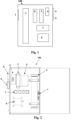
- Figs. 1 and 2 show schematic box diagram and design for water purification and treatment system (100), where a real image of one optional embodiment of the system is shown at Fig 3 .
- the water purification system main part comprises: an optional fan cooling system (1), which is required to thermally stabilize and regulate the temperature water purification and treatment system as a result of possible unwanted internal or external heating sources.
- the cooling system can employ an air fan, a water cooling or other cooling system; a cylindrical air flow ionization chamber (2) made of aluminium, PVC or other chemically inert material, coated with TiO 2 on its internal side ; an electrical ballast (3) for a UV light bulb/lamp, with specifications of power (Watts, Amps, Volts), connected to the local power supply; an electrical breaker circuit (4), added to avoid overloading of the electrical current inside the system; a plurality of gas flow meter devices (5) that can be based on electrical or a mechanical flow rate measurement principles, where flow meters can be configured inside or outside the purification system box (100) and located anywhere inside or outside the purification and treatment site pending on system requirements.
- the gas flow meters monitor and regulate the current air gas flow volumetric rate inside the system (measured in values of Litter Per Minute, LPM).
- a plurality of power meter devices (6) are located in any location at the water purification and treatment site and further monitor and regulate the operational values, the system electrical power, voltage and electrical currents. In another embodiment this system is remotely controlled.
- a plurality of electrical outlets (7) enables power supply connections inside and outside the purification and treatment system.
- the system further comprises compressor air gas (8).
- a regular clean air enters into the compressor or the air is pre-filtered from impurities and contaminations before it enters the ionization chamber with a specific filtering system and is further compressed into the cylindrical tube ionization chamber (2) with the air compressor device (8) (filtering system not shown in the figure).
- Fig. 3 shows one optional setup, in which the air compressor pump (8) is connected to gas flow meter devices (5) and through it to the ionization chamber with air pipes (8a, 8b), respectively.
- the ionization chamber (2) is connected to the external water reservoir inlet (not shown in the related figures) through air gas pipe (2a).
- the compressor can be connected to an air diffuser and/or venturi air pipe line.
- the air pipe (2a) is replaced with a venturi pipe line that guides it efficiently to contaminated water housing container.
- the radicalized air flow rate is enhanced by a secondary air compressor or vacuum pump, located at the output pipe (2a) at different positions.
- the secondary air compressor or vacuum pump push or suck, respectively, the radicalized air toward the diffuser, which is located inside the treated water container or water reservoir.
- the air compressor device is connected to the output pipe (2a) in proximity to its connection to the ionization chamber outlet.
- the connection is made with a T-shape air junction element.
- the connection can optionally utilize a non-return air valve connected to the air compressor output and avoid any leak of radicalized air flow or leak into the compressor.
- the air that flows out of the compressor collides with the radicalized air and accelerates it toward the diffuser which is connected in proximity to its connection to the diffuser device.
- the connection is done through output pipe (2a) outlet, via a T-shape air junction element.
- a non-return air valve can be connected to avoid leak of radicalized air into the pump.
- the radicalized air is accelerated by the air pump toward output pipe outlet into the diffuser.
- the system comprises a remote control and monitoring unit (9) that monitors and controls the system operational values versus their specified ones and can be mechanically or electronically switched between ON and OFF operating states.
- the monitoring unit monitors the voltage and power supply to the system and particularly voltage and power values of the UV lamp, fan, electronic flow meter and other units in the system.
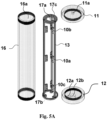
- Figs. 4A-B and 5A-D show schematic design of the air ionization chamber in its assembled and unassembled state, respectively.
- Fig. 4A shows a top perspective view of the external housing of the air ionization chamber, where its assembled parts are shown in Fig. 5A .
- Fig. 4B shows a side perspective view of the chamber internal and external structural design, where the assembled parts are shown in Fig. 5B .
- the air ionization chamber shown in Figs. 4A and 5A comprises: A cylindrical housing tube/cylindrical sleeve (16).
- the tube/sleeve may be made of aluminium and PVC (Polyvinyl chloride which is chemically inert) coated on its internal side with TiO 2 layer to avoid oxidation and damage by the flowing ambient and radicalized air;
- the skeleton may be made of aluminium stainless steel or any hard metal.
- the skeleton (13) is embedded inside the tube/sleeve housing structure (16).
- the frame/skeleton structure is designed with two holding elements (13a,13b) for holding the magnetic rings and an internal space for the UV light bulb/lamp (14).
- the skeleton may further comprise holding elements (10a,10b,10c) from top to bottom at selected distances from each other for holding ferromagnetic rings in a specific configuration (15a,15b,15c).
- the holding elements or seatings may be made of stainless steel and coated with titanium.
- the holding elements (10a, 10b, 10c) may form a single solid unit with the skeleton.
- the inner space in the skeleton for the UV lamp is essentially a cage formed by bars along the z-axis and around the centre of the skeleton. The space has openings in proximity to the skeleton bottom and top sides.
- the magnetic field configuration comprises three sets of concentric cylindrical ferromagnetic rings (15a, 15b, 15c) arranged at selected polarity, occupying an effective small portion of the total volume of the tube chamber.
- the rings are positioned along the z-axis of the skeleton, particularly at top and bottoms sides and center of the tube chamber main axis, where each set comprises magnetic negative and positive poles rings (15e, 15f).
- the rings are arranged with the same polarity.
- the tube and housing are made from chemically and mechanically durable or resistant materials.
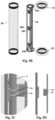
- the UV bulb/lamp (14) can comprise two internal lamps that radiate at two wavelength ranges of 180-195 [nm] and 240-280 [nm], and can be designed and produced in two different types and configuration of either mercury filament or LED light. Further, the lamps electrical connector configurations can include 2 or 4 pins and be located at different locations at their sides depending on the light bulb/lamp type. As shown in Fig. 5C and 5D , each of the ferromagnetic ring seating comprises two cylindrical slots (10e,10f) configured to mechanically hold two corresponding ferromagnetic rings (15e,15f). This design yields a closely packed configuration for the ferromagnetic rings and the UV bulb/lamps (14) located along the central longitudinal axis of the air ionization chamber.
- the ferromagnetic rings are configured to be located close to the UV bulb/lamp radiation source surrounding it at three main locations along the central axis of the air ionization chamber, thus creating three main coupling ionization impact points between the UV radiation and the flowing ambient air Interaction specifically impacts the paramagnetic oxygen component along the ambient air trajectory in the air ionization chamber.
- the external sleeve structure (16) is mechanically attached to top (11) and bottom (12) covers, disks shaped, made of aluminium or stainless steel materials and further coated by TiO 2 layer.
- the top and bottom covers/caps are configured with one or two holes respectively.
- the central holes in the top (11a) and bottom (12a) covers are used as the inlet and outlet for the air flowing through ionization chamber (2), respectively.
- the bottom housing cover may further be designed with a special second input hole (12b) to enable insertion of electrical wiring into and out of the air ionization chamber.
- the internal chamber area, including the housing frame (13), holding elements and chamber cover internal side are coated with TiO 2 to avoid oxidation and damage by the flowing gas inside the chamber.
- the inlet and outlet holes are made out of SS (Stainless Steel) resistant material.
- the covers are mechanically attached to aluminium/SS housing frame (13) at its top and bottom bases (17a, 17b) and external tube structure (16).
- the external connections of the ionization chamber are sealed with Teflon to ensure the required vacuum condition for air that flows inside the chamber.
- the attachment to the top and bottom bases (17a, 17b) are done with special screws, inserted into holes (17c) at the frame top and bottom sides.
- a plurality of adapter and fastening elements are added to the air and electrical inlets and outlets to enable insertion of electrical input and output lines without affecting internal atmospheric pressure. These elements are also used to enable removal of air from the ionization chamber through specially designed air outlets.
- the UV bulbs/lamps had corresponding lengths corresponding to the ionization chamber lengths with nominal powers of 21 and 39 watts, respectively.
- the ionization chamber cleaning properties it was connected to a water reservoir with volume of 1000 litters.
- the ionization chamber with the smaller/higher volume was connected to a small container with volume of 4 litters.
- the UV radiation lamp was identical in all experiments and demonstrations.
- the internal and external pipe diameters at the input and the output of the ionization chamber were 10 mm.
- Figs. 6A-E show perspective side view images of different configurations of the magnetic rings inside the ionization chamber.
- the magnetic rings are carried by holding elements (10) of the skeleton inside the ionization chamber.
- the magnetic rings are symmetrically aligned relative to the main longitudinal central axis of the holding element (10) around the UV bulb (14) and the main central axis of the ionization cylindrical chamber.
- Fig. 6A shows a perspective side view image of the anti-symmetric magnetic field configuration comprising two magnetic sites located at two sides of the carrier holding device (10) inside the ionization chamber. In this configuration, each of the magnetic site comprises two magnetic rings (15e, 15f).
- This configuration is marked as the reference configuration in one preferred embodiment of the present invention.
- Fig. 6B shows a perspective side view image of the magnetic field configuration comprising ionization chamber with no magnetic fields.
- Fig. 6C shows the symmetric configuration of the magnetic field in another embodiment of the present invention.
- the related configuration comprises two magnetic sites, which are located at two sites of the holding element (10) inside the ionization chamber. Each magnetic site comprises two magnetic rings (15e, 15f).
- FIG. 6D shows another optional anti-symmetric magnetic field configuration comprising magnetic rings in another embodiment of the present invention.
- This configuration comprises two magnetic sites located at the two sides of the holding element (10) and ionization chamber.
- Each site comprises two magnetic rings (15e, 15f), which are positioned in opposite magnetic polarization with their south magnetic pole at their proximal sides and north magnetic pole at their distal sides, (NS) (SN).
- Fig. 6E shows the anti-symmetric magnetic field configuration comprising magnetic rings in another preferred embodiment of the present invention.
- each magnetic site comprises two magnetic rings (15e, 15f), which are positioned in an opposite magnetic polarization with their norths magnetic pole at their proximal side and south magnetic poles at their distal sides, i.e., (SN) (NS) three magnetic sites.
- Fig. 7A shows top view images of a DPD gauge crucible filled with coloured water which indicates presence of some oxygen radical concentration.
- the DPD gauge is filled with water and dissolved DPD material and a certain amount of oxygen radicles, which results in a certain colour intensity.
- the experimental results for the ionization chamber setup, presented in Figs. 1-5 reflect experiments done with a small partially closed small size water container with veturi pump and a diffuser at its outlet.
- the container internal volume was 4 litters which and filled to almost full capacity with a 3.7 litters of water.
- the experimental results shown in the related table were performed for ionization chamber with magnetic rings in the anti-symmetric reference configuration, (SN) (NS), with two magnetic sites, shown in Fig. 6A , and ionization chamber without magnetic field, as shown in Fig. 6B .
- the experimental results were arranged in a table according to oxygen gas radical flow value and specific configuration inside the ionization chamber.
- the ionization chamber (2) was turned to ON "state” to generate the oxygenated gas radicals, which flew into the water container trough venturi pump (2a) and a diffuser.
- the water container reaches a steady state after time, T0. After the water container reaches a steady state, a chemical DPD measurement is performed.
- the DPD chemical measurements are performed by inserting the DPD gauge into the water container in a connected vessel configuration.
- a DPD pill is then inserted into the DPD gauge, quickly dissolved inside the DPD gauge water and performs a chemical reaction with the radicals that enter the gauge top side from the water container.
- the chemical interaction modifies the colour of the water in the attached test water container.
- the color of the radicalized water is modified from a transparent water regular color to a dark pink color, depending on the radicals concentration inside the gauge device.
- the values of the corresponding intensity are evaluated by using the DPD color intensity table shown in Fig. 7B .
- the specific DPD color-intensity scale is calibrated for ionized chlorine.
- preliminary experiments establish that it is interacts with oxygen radicals and hydrogen peroxide.
- we have performed preliminary experiments. In these experiments, we have tested the ionization chamber without magnetic field with and without a UV bulb at different compression flows. In the experiments without an active UV bulb, we found that water color in the container was transparent as the regular water color. In further experiments, we turned the UV bulb on, and set the compression flow to a value of F 4 litter/min.
- the main reactants that participate in the cleaning processing of the contaminated water and further chemically interact with DPD are components i and ii.
- reacting/product component i free radicals which are encapsulated inside air bubbles
- the main phase of the radicals are bubbles that diffuse into water in the container, flow up into the air-water interface due to buoyancy forces, thereby creating arrays of bubbles along that interface.
- the bubbles that flow through the water reservoir serve as agents that deliver the radicals to direct interaction with the various contaminations which flow inside the treated water.
- the bubbles which do not interact with contaminations, flow up and float at the air-water interface as a result of buoyancy forces. Due to various physical reasons, the partial percentage of the floating bubbles that do not react with contaminations have an average finite life time which results in their explosion into the surrounding air and/or into the treated water. Another component of bubbles that dissolves in the water releases the encapsulated free radicals into the treated water. These mechanisms produce secondary reduction mechanism with liquid hydrogen peroxide.
- the water reservoir is fully or at least partially closed.
- the water reservoir is subjected to a high intrinsic internal pressure along the air-water interface as a result of the ejected gas phase of the radicalized/excited gas. This is also in accordance with Henry's Law regarding equilibrium between liquid and gas phase concentrations of any particular species.
- the atmospheric pressure is enhanced by an external pressure applied to the water reservoir. In both previous embodiments, there is enhanced interaction of the oxygen gas radicals that flow above the water with water in the reservoir, which results in another generation mechanism of H 2 O 2 liquid which further cleans the contaminated water. All said reactants comprising free radicals inside the bubbles and H 2 O 2 react with the dissolved DPD , thereby modifying the water color in the water container.
- Figs. 8A-B show the full DPD experimental results demonstrated in Fig. 7 .
- Fig. 8A shows the radical concentration, n, at different compression flow values.
- Fig. 8B shows the steady state time stabilization, T0, of the system. Experiments were performed inside a small water container, using the DPD experimental gauge device, shown in Fig. 7A .
- Figs. 6 A, C-E These configurations represent some exemplary optional embodiments of the ionization chamber system. Experiments were performed at compression rate, F , of 4-14 litter/min.
- the magnetic field configurations in Figs. 6 A, C-D comprise two magnetic sites located around the cylindrical ionization chamber main longitudinal axis, close to its bottom and top ends and adjacent to its air inlet and outlet, respectively.
- the magnetic field configuration in Fig. 6E comprises three magnetic sites, with one site additional to the two previous magnetic sites, which is located at the center of the cylindrical ionization chamber.
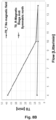
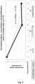
- Fig. 10 shows graphs of the radicals concentration experimental results versus compression air flow multiplied by the stabilization time T0 for different compression flow, F .
- the concentration of the reference anti-symmetric configuration is n m ⁇ 8-9 times higher than that of the chamber without magnetic field.
Landscapes
- Chemical & Material Sciences (AREA)
- Organic Chemistry (AREA)
- Health & Medical Sciences (AREA)
- Life Sciences & Earth Sciences (AREA)
- Hydrology & Water Resources (AREA)
- Engineering & Computer Science (AREA)
- Environmental & Geological Engineering (AREA)
- Water Supply & Treatment (AREA)
- General Health & Medical Sciences (AREA)
- Toxicology (AREA)
- Inorganic Chemistry (AREA)
- Public Health (AREA)
- Chemical Kinetics & Catalysis (AREA)
- Epidemiology (AREA)
- Animal Behavior & Ethology (AREA)
- Veterinary Medicine (AREA)
- Electromagnetism (AREA)
- Physics & Mathematics (AREA)
- Water Treatment By Electricity Or Magnetism (AREA)
- Physical Water Treatments (AREA)
- Electrical Discharge Machining, Electrochemical Machining, And Combined Machining (AREA)
- Excavating Of Shafts Or Tunnels (AREA)
- Physical Or Chemical Processes And Apparatus (AREA)
Claims (14)
- Système de purification d'eau (100) comprenant :une chambre cylindrique (2) comprenant une entrée et une sortie pour faire circuler l'air entrant et sortant dans ladite chambre (2) et hors de ladite chambre (2) et dans un réservoir contenant de l'eau ;au moins une lampe à rayonnement UV allongée (14) située au centre de ladite chambre cylindrique (2) ;au moins une paire d'anneaux magnétiques (15a, 15b, 15c) ;un compresseur d'air (8), des tuyaux d'air (8a) destinés à introduire ledit air gazeux dans ladite chambre et un tuyau d'air de sortie (2a) destiné à introduire ledit air gazeux modifié dans ledit réservoir contenantde l'eau ;un préfiltre fixé audit compresseur d'air (8) et situé avant l'entrée de ladite chambre (2) ; etune structure (13) conçue pour occuper le volume central de ladite chambre (2) de haut en bas autour de l'axe longitudinal central de ladite chambre (2), ladite structure (13) comprenant un espace interne destiné à recevoir ladite au moins une lampe à rayonnement UV (14) et au moins une paire d'éléments de maintien (10a, 10b, 10c) destinés à maintenir ladite au moins une paire d'anneaux magnétiques (15a, 15b, 15c) autour de ladite au moins une lampe à rayonnement UV (14), ledit diamètre interne des bases (17b, 17c) de ladite structure (13) étant plus petit que le diamètre interne d'un manchon (16) de boîtier, ledit manchon (16) de boîtier étant relié au niveau des extrémités opposées aux couvercles supérieur (11) et inférieur (12), lesdits couvercles supérieur (11) et inférieur (12) étant chacun dotés de trous centraux respectifs (11a, 12a), et chaque paire d'anneaux magnétiques (15e, 15f) générant un champ magnétique local lors de la mise en place desdites paires d'anneaux magnétiques (15e, 15f) sur lesdits éléments de maintien (10a, 10b, 10c) de ladite structure (13), ledit champ magnétique local ne chevauchant pas ou n'interférant pas au moins de manière minime avec un champ magnétique local généré par une paire voisine d'anneaux magnétiques (15e, 15f), ledit système de purification (100) comprenant une configuration concentrique pour perturber de manière minime le profil et la distribution dudit air entrant et sortant, ladite au moins une paire d'anneaux magnétiques (15a, 15b, 15c) étant positionnés parallèlement l'un par rapport à l'autre et conçus pour induire un champ de flux magnétique concentrique sur des molécules dudit écoulement d'air entrant et sortant.
- Système de purification d'eau (100) selon la revendication 1, ladite au moins une lampe à rayonnement UV (14) comprenant deux lampes avec deux plages de longueurs d'onde de 180-195 [nm] et de 240-280 [nm].
- Système de purification d'eau (100) selon la revendication 1, ladite chambre (2) étant constituée d'un matériau conducteur revêtu d'un matériau chimiquement inerte.
- Système de purification d'eau (100) selon la revendication 1, ladite chambre (2) comprenant en outre un manchon extérieur et des couvercles supérieur et inférieur (11, 12) étant fixés mécaniquement aux côtés supérieur et inférieur dudit manchon extérieur et fermant les extrémités supérieure et inférieure de ladite chambre (2).
- Système de purification d'eau (100) selon la revendication 1, comprenant en outre une pluralité de débitmètres de gaz (5), lesdits débitmètres de gaz (5) sont montés à l'intérieur ou à l'extérieur d'un boîtier encapsulant ladite chambre (2).
- Système de purification d'eau (100) selon la revendication 1, comprenant en outre une unité de commande à distance destinée à commander des valeurs fonctionnelles par rapport aux valeurs spécifiées dudit système (100), ladite unité étant conçue pour commuter entre les états de fonctionnement activé et désactivé dudit système, mécaniquement ou électroniquement et surveiller la tension, le courant électrique, l'alimentation électrique et les dispositifs associés dudit système (100).
- Système de purification d'eau selon la revendication 6, lesdits dispositifs étant sélectionnés parmi ladite au moins une lampe UV (14), un ventilateur (1) destiné à expulser la chaleur générée dans ladite chambre (2) hors dudit système (100) et un débitmètre d'air électronique (5) destiné à surveiller l'air entrant et sortant de ladite chambre (2) à l'intérieur dudit système (100).
- Système de purification d'eau (100) selon la revendication 1, comprenant en outre un tuyau venturi (2a) fixé à ladite sortie de ladite chambre destiné à transporter l'air radicalisé/excité et ambiant dans le réservoir d'eau traitée.
- Système de purification d'eau (100) selon la revendication 1, comprenant en outre un récipient d'eau ou un réservoir d'eau en communication fluidique avec ladite chambre (2).
- Système de purification d'eau (100) selon la revendication 1, ladite chambre (2) comportant une forme géométrique cylindrique avec ledit manchon (16) de boîtier et ledit cadre de boîtier comportant une forme géométrique cylindrique correspondante.
- Système de purification d'eau (100) selon la revendication 1, comprenant trois paires d'anneaux magnétiques (15a, 15b, 15c) agencés selon une configuration de polarité identique au niveau des extrémités supérieure et inférieure, au centre et autour de l'axe longitudinal central principal de ladite chambre (2), chacune desdites paires d'anneaux magnétiques (15a, 15b, 15c) comprenant un anneau à polarité négative et un second anneau à polarité positive, ladite configuration de polarité étant une configuration antisymétrique, lesdits anneaux étant maintenus mécaniquement par lesdits éléments de maintien (10a, 10b, 10c).
- Système de purification d'eau (100) selon la revendication 11, lesdits anneaux magnétiques générant une intensité de champ magnétique dans la plage de 10-3 à 106 gauss, ladite plage étant suffisante pour induire un flux magnétique élevé dans ladite chambre (2) et radicaliser l'air ambiant entrant.
- Système de purification d'eau (100) selon la revendication 1, ladite structure (13) comprenant des barres longitudinales externes s'étendant de haut en bas de ladite structure autour de l'espace interne pour recevoir ladite au moins une lampe à rayonnement UV (14), et des éléments de maintien (10a, 10b, 10c) s'étendant vers l'intérieur à partir desdites barres externes et comprenant des évidements destinés à maintenir ladite au moins une paire d'anneaux magnétiques (15a, 15b, 15c) autour de ladite au moins une lampe à rayonnement UV, lesdites barres externes et lesdits éléments de maintien formant une seule unité solide de ladite structure.
- Système de purification d'eau (100) selon la revendication 1, comprenant en outre un appareil de préfiltration destiné à nettoyer l'air entrant ambiant des impuretés et contaminations avant de l'injecter dans ladite chambre (2) et un diffuseur raccordé à la sortie de ladite chambre destiné à diffuser de l'air radicalisé dans un réservoir d'eau.
Applications Claiming Priority (2)
| Application Number | Priority Date | Filing Date | Title |
|---|---|---|---|
| IL256745A IL256745B2 (en) | 2018-01-04 | 2018-01-04 | Water purification system |
| PCT/IL2019/050025 WO2019135239A1 (fr) | 2018-01-04 | 2019-01-04 | Système de traitement de l'eau |
Publications (3)
| Publication Number | Publication Date |
|---|---|
| EP3735397A1 EP3735397A1 (fr) | 2020-11-11 |
| EP3735397B1 true EP3735397B1 (fr) | 2024-08-21 |
| EP3735397C0 EP3735397C0 (fr) | 2024-08-21 |
Family
ID=61274021
Family Applications (1)
| Application Number | Title | Priority Date | Filing Date |
|---|---|---|---|
| EP19702128.0A Active EP3735397B1 (fr) | 2018-01-04 | 2019-01-04 | Système de traitement de l'eau |
Country Status (7)
| Country | Link |
|---|---|
| US (1) | US20210206663A1 (fr) |
| EP (1) | EP3735397B1 (fr) |
| EA (1) | EA202091622A1 (fr) |
| ES (1) | ES2999686T3 (fr) |
| IL (1) | IL256745B2 (fr) |
| PL (1) | PL3735397T3 (fr) |
| WO (1) | WO2019135239A1 (fr) |
Families Citing this family (3)
| Publication number | Priority date | Publication date | Assignee | Title |
|---|---|---|---|---|
| CN111693805A (zh) * | 2020-05-28 | 2020-09-22 | 珠海格力电器股份有限公司 | 一种检测杀菌装置运行状态的检测电路及检测方法 |
| CN120225470A (zh) * | 2022-10-31 | 2025-06-27 | 波洛萨诺有限公司 | 水处理系统 |
| CN120774611B (zh) * | 2025-08-11 | 2026-03-20 | 浙江晧月水务科技有限公司 | 一种磁性水过滤器 |
Family Cites Families (13)
| Publication number | Priority date | Publication date | Assignee | Title |
|---|---|---|---|---|
| GB991384A (en) * | 1963-04-27 | 1965-05-05 | British Oxygen Co Ltd | Method and apparatus for storing ozone/oxygen mixtures |
| US4655933A (en) * | 1982-04-01 | 1987-04-07 | Johnson Dennis E J | System of ionized oxygen allotrope gas water purification and method and apparatus therefor |
| US5223105A (en) * | 1989-06-29 | 1993-06-29 | Arthurson Corporation Pty. Ltd. | Ozone generator |
| US5622622A (en) * | 1995-01-25 | 1997-04-22 | Aqua-Ion Systems, Inc. | Ultraviolet sterilizer and source of ionized molecules for electrocoalescent/magnetic separation (ECMS) removal of contaminants from water streams |
| DE19641152C2 (de) * | 1996-10-07 | 1998-09-17 | Lemfoerder Metallwaren Ag | Kraftfahrzeuglenksäuleneinheit |
| US5929324A (en) * | 1997-08-08 | 1999-07-27 | Taiwan Semiconductor Manufacturing Co., Ltd. | Apparatus for detecting leakage in a gas reactor |
| US6056872A (en) * | 1998-02-06 | 2000-05-02 | The Magnetizer Group, Inc. | Magnetic device for the treatment of fluids |
| US7407593B2 (en) * | 2005-09-20 | 2008-08-05 | Frederick Jr William Mcdowell | Deodorization of livestock waste using ozone |
| US7564201B2 (en) * | 2006-08-04 | 2009-07-21 | Clearwater Technology, LLC | Intelligent gas discharge lamp control circuit |
| US9321655B2 (en) | 2009-08-20 | 2016-04-26 | Kellogg Brown & Root Llc | Systems and methods for producing syngas and products therefrom |
| ES2657897T3 (es) | 2011-04-12 | 2018-03-07 | Silver Bullet Water Treatment Company, Llc | Sistemas y método de tratamiento de agua mediante radiación UV |
| US20160083275A1 (en) * | 2014-09-19 | 2016-03-24 | Aardvark Ip Holding, Llc | Water treatment systems and methods |
| KR102215591B1 (ko) * | 2016-11-17 | 2021-03-08 | 아이앤비에어 주식회사 | 자외선 반사판이 형성된 공기정화살균기 |
-
2018
- 2018-01-04 IL IL256745A patent/IL256745B2/en unknown
-
2019
- 2019-01-04 PL PL19702128.0T patent/PL3735397T3/pl unknown
- 2019-01-04 EA EA202091622A patent/EA202091622A1/ru unknown
- 2019-01-04 US US16/960,034 patent/US20210206663A1/en active Pending
- 2019-01-04 WO PCT/IL2019/050025 patent/WO2019135239A1/fr not_active Ceased
- 2019-01-04 ES ES19702128T patent/ES2999686T3/es active Active
- 2019-01-04 EP EP19702128.0A patent/EP3735397B1/fr active Active
Also Published As
| Publication number | Publication date |
|---|---|
| WO2019135239A1 (fr) | 2019-07-11 |
| EA202091622A1 (ru) | 2020-12-09 |
| EP3735397C0 (fr) | 2024-08-21 |
| PL3735397T3 (pl) | 2025-02-03 |
| EP3735397A1 (fr) | 2020-11-11 |
| ES2999686T3 (en) | 2025-02-26 |
| IL256745B (en) | 2022-11-01 |
| IL256745A (en) | 2018-02-28 |
| US20210206663A1 (en) | 2021-07-08 |
| IL256745B2 (en) | 2023-03-01 |
Similar Documents
| Publication | Publication Date | Title |
|---|---|---|
| EP3735397B1 (fr) | Système de traitement de l'eau | |
| US4563286A (en) | System of ionized oxygen allotrope gas water purification and method and apparatus therefor | |
| US4655933A (en) | System of ionized oxygen allotrope gas water purification and method and apparatus therefor | |
| CN101177315B (zh) | 水消毒设备 | |
| CA1120890A (fr) | Conversion de l'oxygene moleculaire en ozone par irradiation a partir de deuterium gazeux ionise | |
| ES2657897T3 (es) | Sistemas y método de tratamiento de agua mediante radiación UV | |
| US7387724B1 (en) | Fluid magnetizer | |
| US20160083275A1 (en) | Water treatment systems and methods | |
| CN102115232A (zh) | 水体自发电电解还原模块 | |
| US20060226060A1 (en) | Water treatment turbine apparatus and method | |
| US20250333334A1 (en) | Water treatment system | |
| CA1178554A (fr) | Systeme de purification de l'eau a l'aide d'un gaz allotrope d'oxygene ionise; methode et appareil utilises a cette fin | |
| EA042627B1 (ru) | Система очистки воды | |
| CN106992110B (zh) | 一种集成冷却装置的高亮度紫外光源 | |
| JP3221166U (ja) | 水の処理装置 | |
| CA1289511C (fr) | Systeme de purificatio de l'eau par l'oxygene allotrope gazeux ionise, ainsi que methode et appareillage pour ce systeme | |
| KR20000006771A (ko) | 활성정수의 멸균장치 및 그 제조방법. | |
| KR200187879Y1 (ko) | 산업용 오존발생장치 | |
| KR20250007614A (ko) | 유체의 이온화를 위한 방법 및 디바이스 | |
| KR20250006278A (ko) | 유체의 이온화를 위한 방법 | |
| CN112441646A (zh) | 一种污水处理装置 | |
| KR20250007623A (ko) | 유체의 이온화를 위한 디바이스 | |
| KR20250006268A (ko) | 유체의 이온화를 위한 방법 | |
| KR20250004034A (ko) | 유체의 이온화를 위한 디바이스 | |
| WO2004059653A1 (fr) | Generateur d'hydrogene au plasma |
Legal Events
| Date | Code | Title | Description |
|---|---|---|---|
| STAA | Information on the status of an ep patent application or granted ep patent |
Free format text: STATUS: UNKNOWN |
|
| STAA | Information on the status of an ep patent application or granted ep patent |
Free format text: STATUS: THE INTERNATIONAL PUBLICATION HAS BEEN MADE |
|
| PUAI | Public reference made under article 153(3) epc to a published international application that has entered the european phase |
Free format text: ORIGINAL CODE: 0009012 |
|
| STAA | Information on the status of an ep patent application or granted ep patent |
Free format text: STATUS: REQUEST FOR EXAMINATION WAS MADE |
|
| 17P | Request for examination filed |
Effective date: 20200722 |
|
| AK | Designated contracting states |
Kind code of ref document: A1 Designated state(s): AL AT BE BG CH CY CZ DE DK EE ES FI FR GB GR HR HU IE IS IT LI LT LU LV MC MK MT NL NO PL PT RO RS SE SI SK SM TR |
|
| AX | Request for extension of the european patent |
Extension state: BA ME |
|
| DAV | Request for validation of the european patent (deleted) | ||
| DAX | Request for extension of the european patent (deleted) | ||
| STAA | Information on the status of an ep patent application or granted ep patent |
Free format text: STATUS: EXAMINATION IS IN PROGRESS |
|
| 17Q | First examination report despatched |
Effective date: 20211124 |
|
| GRAP | Despatch of communication of intention to grant a patent |
Free format text: ORIGINAL CODE: EPIDOSNIGR1 |
|
| STAA | Information on the status of an ep patent application or granted ep patent |
Free format text: STATUS: GRANT OF PATENT IS INTENDED |
|
| INTG | Intention to grant announced |
Effective date: 20231010 |
|
| GRAS | Grant fee paid |
Free format text: ORIGINAL CODE: EPIDOSNIGR3 |
|
| GRAJ | Information related to disapproval of communication of intention to grant by the applicant or resumption of examination proceedings by the epo deleted |
Free format text: ORIGINAL CODE: EPIDOSDIGR1 |
|
| GRAL | Information related to payment of fee for publishing/printing deleted |
Free format text: ORIGINAL CODE: EPIDOSDIGR3 |
|
| STAA | Information on the status of an ep patent application or granted ep patent |
Free format text: STATUS: EXAMINATION IS IN PROGRESS |
|
| INTC | Intention to grant announced (deleted) | ||
| GRAP | Despatch of communication of intention to grant a patent |
Free format text: ORIGINAL CODE: EPIDOSNIGR1 |
|
| STAA | Information on the status of an ep patent application or granted ep patent |
Free format text: STATUS: GRANT OF PATENT IS INTENDED |
|
| INTG | Intention to grant announced |
Effective date: 20240319 |
|
| GRAA | (expected) grant |
Free format text: ORIGINAL CODE: 0009210 |
|
| STAA | Information on the status of an ep patent application or granted ep patent |
Free format text: STATUS: THE PATENT HAS BEEN GRANTED |
|
| AK | Designated contracting states |
Kind code of ref document: B1 Designated state(s): AL AT BE BG CH CY CZ DE DK EE ES FI FR GB GR HR HU IE IS IT LI LT LU LV MC MK MT NL NO PL PT RO RS SE SI SK SM TR |
|
| RAP1 | Party data changed (applicant data changed or rights of an application transferred) |
Owner name: POLLOSANO LTD |
|
| REG | Reference to a national code |
Ref country code: GB Ref legal event code: FG4D |
|
| REG | Reference to a national code |
Ref country code: CH Ref legal event code: EP |
|
| REG | Reference to a national code |
Ref country code: IE Ref legal event code: FG4D |
|
| REG | Reference to a national code |
Ref country code: DE Ref legal event code: R096 Ref document number: 602019057330 Country of ref document: DE |
|
| U01 | Request for unitary effect filed |
Effective date: 20240821 |
|
| U07 | Unitary effect registered |
Designated state(s): AT BE BG DE DK EE FI FR IT LT LU LV MT NL PT RO SE SI Effective date: 20240902 |
|
| PG25 | Lapsed in a contracting state [announced via postgrant information from national office to epo] |
Ref country code: NO Free format text: LAPSE BECAUSE OF FAILURE TO SUBMIT A TRANSLATION OF THE DESCRIPTION OR TO PAY THE FEE WITHIN THE PRESCRIBED TIME-LIMIT Effective date: 20241121 |
|
| PG25 | Lapsed in a contracting state [announced via postgrant information from national office to epo] |
Ref country code: GR Free format text: LAPSE BECAUSE OF FAILURE TO SUBMIT A TRANSLATION OF THE DESCRIPTION OR TO PAY THE FEE WITHIN THE PRESCRIBED TIME-LIMIT Effective date: 20241122 |
|
| U20 | Renewal fee for the european patent with unitary effect paid |
Year of fee payment: 7 Effective date: 20241218 |
|
| PG25 | Lapsed in a contracting state [announced via postgrant information from national office to epo] |
Ref country code: IS Free format text: LAPSE BECAUSE OF FAILURE TO SUBMIT A TRANSLATION OF THE DESCRIPTION OR TO PAY THE FEE WITHIN THE PRESCRIBED TIME-LIMIT Effective date: 20241221 |
|
| PG25 | Lapsed in a contracting state [announced via postgrant information from national office to epo] |
Ref country code: HR Free format text: LAPSE BECAUSE OF FAILURE TO SUBMIT A TRANSLATION OF THE DESCRIPTION OR TO PAY THE FEE WITHIN THE PRESCRIBED TIME-LIMIT Effective date: 20240821 |
|
| PG25 | Lapsed in a contracting state [announced via postgrant information from national office to epo] |
Ref country code: RS Free format text: LAPSE BECAUSE OF FAILURE TO SUBMIT A TRANSLATION OF THE DESCRIPTION OR TO PAY THE FEE WITHIN THE PRESCRIBED TIME-LIMIT Effective date: 20241121 |
|
| PG25 | Lapsed in a contracting state [announced via postgrant information from national office to epo] |
Ref country code: RS Free format text: LAPSE BECAUSE OF FAILURE TO SUBMIT A TRANSLATION OF THE DESCRIPTION OR TO PAY THE FEE WITHIN THE PRESCRIBED TIME-LIMIT Effective date: 20241121 Ref country code: NO Free format text: LAPSE BECAUSE OF FAILURE TO SUBMIT A TRANSLATION OF THE DESCRIPTION OR TO PAY THE FEE WITHIN THE PRESCRIBED TIME-LIMIT Effective date: 20241121 Ref country code: IS Free format text: LAPSE BECAUSE OF FAILURE TO SUBMIT A TRANSLATION OF THE DESCRIPTION OR TO PAY THE FEE WITHIN THE PRESCRIBED TIME-LIMIT Effective date: 20241221 Ref country code: HR Free format text: LAPSE BECAUSE OF FAILURE TO SUBMIT A TRANSLATION OF THE DESCRIPTION OR TO PAY THE FEE WITHIN THE PRESCRIBED TIME-LIMIT Effective date: 20240821 Ref country code: GR Free format text: LAPSE BECAUSE OF FAILURE TO SUBMIT A TRANSLATION OF THE DESCRIPTION OR TO PAY THE FEE WITHIN THE PRESCRIBED TIME-LIMIT Effective date: 20241122 |
|
| REG | Reference to a national code |
Ref country code: ES Ref legal event code: FG2A Ref document number: 2999686 Country of ref document: ES Kind code of ref document: T3 Effective date: 20250226 |
|
| U1N | Appointed representative for the unitary patent procedure changed after the registration of the unitary effect |
Representative=s name: HARRISON IP LIMITED; GB |
|
| PG25 | Lapsed in a contracting state [announced via postgrant information from national office to epo] |
Ref country code: SM Free format text: LAPSE BECAUSE OF FAILURE TO SUBMIT A TRANSLATION OF THE DESCRIPTION OR TO PAY THE FEE WITHIN THE PRESCRIBED TIME-LIMIT Effective date: 20240821 |
|
| PG25 | Lapsed in a contracting state [announced via postgrant information from national office to epo] |
Ref country code: CZ Free format text: LAPSE BECAUSE OF FAILURE TO SUBMIT A TRANSLATION OF THE DESCRIPTION OR TO PAY THE FEE WITHIN THE PRESCRIBED TIME-LIMIT Effective date: 20240821 |
|
| PG25 | Lapsed in a contracting state [announced via postgrant information from national office to epo] |
Ref country code: SK Free format text: LAPSE BECAUSE OF FAILURE TO SUBMIT A TRANSLATION OF THE DESCRIPTION OR TO PAY THE FEE WITHIN THE PRESCRIBED TIME-LIMIT Effective date: 20240821 |
|
| PLBE | No opposition filed within time limit |
Free format text: ORIGINAL CODE: 0009261 |
|
| STAA | Information on the status of an ep patent application or granted ep patent |
Free format text: STATUS: NO OPPOSITION FILED WITHIN TIME LIMIT |
|
| 26N | No opposition filed |
Effective date: 20250522 |
|
| REG | Reference to a national code |
Ref country code: CH Ref legal event code: PL |
|
| PG25 | Lapsed in a contracting state [announced via postgrant information from national office to epo] |
Ref country code: MC Free format text: LAPSE BECAUSE OF FAILURE TO SUBMIT A TRANSLATION OF THE DESCRIPTION OR TO PAY THE FEE WITHIN THE PRESCRIBED TIME-LIMIT Effective date: 20240821 |
|
| PG25 | Lapsed in a contracting state [announced via postgrant information from national office to epo] |
Ref country code: CH Free format text: LAPSE BECAUSE OF NON-PAYMENT OF DUE FEES Effective date: 20250131 |
|
| PG25 | Lapsed in a contracting state [announced via postgrant information from national office to epo] |
Ref country code: IE Free format text: LAPSE BECAUSE OF NON-PAYMENT OF DUE FEES Effective date: 20250104 |
|
| PGFP | Annual fee paid to national office [announced via postgrant information from national office to epo] |
Ref country code: PL Payment date: 20251219 Year of fee payment: 8 |
|
| U20 | Renewal fee for the european patent with unitary effect paid |
Year of fee payment: 8 Effective date: 20260119 |
|
| PGFP | Annual fee paid to national office [announced via postgrant information from national office to epo] |
Ref country code: GB Payment date: 20260119 Year of fee payment: 8 |
|
| PGFP | Annual fee paid to national office [announced via postgrant information from national office to epo] |
Ref country code: ES Payment date: 20260202 Year of fee payment: 8 |