EP3735378B1 - Akustische behandlungsstruktur für die gondel eines triebwerks eines flugzeugs - Google Patents
Akustische behandlungsstruktur für die gondel eines triebwerks eines flugzeugs Download PDFInfo
- Publication number
- EP3735378B1 EP3735378B1 EP19703148.7A EP19703148A EP3735378B1 EP 3735378 B1 EP3735378 B1 EP 3735378B1 EP 19703148 A EP19703148 A EP 19703148A EP 3735378 B1 EP3735378 B1 EP 3735378B1
- Authority
- EP
- European Patent Office
- Prior art keywords
- skin
- modules
- acoustic treatment
- stiffeners
- acoustic
- Prior art date
- Legal status (The legal status is an assumption and is not a legal conclusion. Google has not performed a legal analysis and makes no representation as to the accuracy of the status listed.)
- Active
Links
Images


Classifications
-
- B—PERFORMING OPERATIONS; TRANSPORTING
- B64—AIRCRAFT; AVIATION; COSMONAUTICS
- B64C—AEROPLANES; HELICOPTERS
- B64C7/00—Structures or fairings not otherwise provided for
- B64C7/02—Nacelles
-
- F—MECHANICAL ENGINEERING; LIGHTING; HEATING; WEAPONS; BLASTING
- F02—COMBUSTION ENGINES; HOT-GAS OR COMBUSTION-PRODUCT ENGINE PLANTS
- F02K—JET-PROPULSION PLANTS
- F02K1/00—Plants characterised by the form or arrangement of the jet pipe or nozzle; Jet pipes or nozzles peculiar thereto
- F02K1/78—Other construction of jet pipes
- F02K1/82—Jet pipe walls, e.g. liners
- F02K1/827—Sound absorbing structures or liners
-
- B—PERFORMING OPERATIONS; TRANSPORTING
- B64—AIRCRAFT; AVIATION; COSMONAUTICS
- B64D—EQUIPMENT FOR FITTING IN OR TO AIRCRAFT; FLIGHT SUITS; PARACHUTES; ARRANGEMENT OR MOUNTING OF POWER PLANTS OR PROPULSION TRANSMISSIONS IN AIRCRAFT
- B64D33/00—Arrangement in aircraft of power plant parts or auxiliaries not otherwise provided for
- B64D33/04—Arrangement in aircraft of power plant parts or auxiliaries not otherwise provided for of exhaust outlets or jet pipes
- B64D33/06—Silencing exhaust or propulsion jets
-
- F—MECHANICAL ENGINEERING; LIGHTING; HEATING; WEAPONS; BLASTING
- F02—COMBUSTION ENGINES; HOT-GAS OR COMBUSTION-PRODUCT ENGINE PLANTS
- F02C—GAS-TURBINE PLANTS; AIR INTAKES FOR JET-PROPULSION PLANTS; CONTROLLING FUEL SUPPLY IN AIR-BREATHING JET-PROPULSION PLANTS
- F02C7/00—Features, components parts, details or accessories, not provided for in, or of interest apart form groups F02C1/00 - F02C6/00; Air intakes for jet-propulsion plants
- F02C7/04—Air intakes for gas-turbine plants or jet-propulsion plants
- F02C7/045—Air intakes for gas-turbine plants or jet-propulsion plants having provisions for noise suppression
-
- B—PERFORMING OPERATIONS; TRANSPORTING
- B64—AIRCRAFT; AVIATION; COSMONAUTICS
- B64D—EQUIPMENT FOR FITTING IN OR TO AIRCRAFT; FLIGHT SUITS; PARACHUTES; ARRANGEMENT OR MOUNTING OF POWER PLANTS OR PROPULSION TRANSMISSIONS IN AIRCRAFT
- B64D33/00—Arrangement in aircraft of power plant parts or auxiliaries not otherwise provided for
- B64D33/02—Arrangement in aircraft of power plant parts or auxiliaries not otherwise provided for of combustion air intakes
- B64D2033/0206—Arrangement in aircraft of power plant parts or auxiliaries not otherwise provided for of combustion air intakes comprising noise reduction means, e.g. acoustic liners
-
- F—MECHANICAL ENGINEERING; LIGHTING; HEATING; WEAPONS; BLASTING
- F05—INDEXING SCHEMES RELATING TO ENGINES OR PUMPS IN VARIOUS SUBCLASSES OF CLASSES F01-F04
- F05D—INDEXING SCHEME FOR ASPECTS RELATING TO NON-POSITIVE-DISPLACEMENT MACHINES OR ENGINES, GAS-TURBINES OR JET-PROPULSION PLANTS
- F05D2260/00—Function
- F05D2260/30—Retaining components in desired mutual position
- F05D2260/38—Retaining components in desired mutual position by a spring, i.e. spring loaded or biased towards a certain position
-
- F—MECHANICAL ENGINEERING; LIGHTING; HEATING; WEAPONS; BLASTING
- F05—INDEXING SCHEMES RELATING TO ENGINES OR PUMPS IN VARIOUS SUBCLASSES OF CLASSES F01-F04
- F05D—INDEXING SCHEME FOR ASPECTS RELATING TO NON-POSITIVE-DISPLACEMENT MACHINES OR ENGINES, GAS-TURBINES OR JET-PROPULSION PLANTS
- F05D2260/00—Function
- F05D2260/96—Preventing, counteracting or reducing vibration or noise
- F05D2260/963—Preventing, counteracting or reducing vibration or noise by Helmholtz resonators
-
- Y—GENERAL TAGGING OF NEW TECHNOLOGICAL DEVELOPMENTS; GENERAL TAGGING OF CROSS-SECTIONAL TECHNOLOGIES SPANNING OVER SEVERAL SECTIONS OF THE IPC; TECHNICAL SUBJECTS COVERED BY FORMER USPC CROSS-REFERENCE ART COLLECTIONS [XRACs] AND DIGESTS
- Y02—TECHNOLOGIES OR APPLICATIONS FOR MITIGATION OR ADAPTATION AGAINST CLIMATE CHANGE
- Y02T—CLIMATE CHANGE MITIGATION TECHNOLOGIES RELATED TO TRANSPORTATION
- Y02T50/00—Aeronautics or air transport
- Y02T50/60—Efficient propulsion technologies, e.g. for aircraft
Definitions
- the present invention relates to the field of the acoustic treatment of aircraft propulsion assembly nacelles.
- a propulsion assembly for example a turbojet engine
- several structures or parts of the nacelle generally include acoustic panels.
- An acoustic panel typically comprises two skins and a cellular core of the honeycomb type sandwiched between the two skins.
- the alveolar core consists of transverse partitions contributing to the structural strength of the panel by ensuring in particular the connection between the two skins.
- One of the skins, oriented towards the noise source, is acoustically permeable in order to capture the acoustic waves and reduce the acoustic energy within the alveolar core.
- the exhaust cone and the primary nozzle of the exhaust nozzle typically include such acoustic panels.
- acoustic panels of the exhaust nozzle are typically made of superalloys or ceramic matrix composite materials which make them expensive to manufacture.
- FR 3041937 A1 and US 5594246A each disclose a nacelle comprising acoustic panels.
- An object of the present invention is to propose a structure provided with an acoustic treatment function for an aircraft propulsion assembly nacelle, reducing manufacturing costs and offering good thermomechanical performance, in particular when this structure constitutes all or part of an exhaust cone or a primary exhaust nozzle.
- the invention relates to a structure for an aircraft propulsion assembly nacelle comprising a first skin, stiffeners fixed to the first skin to stiffen this first skin, and acoustic treatment modules.
- Each acoustic treatment module comprises a honeycomb core and a second skin attached to the honeycomb core.
- the first skin and the acoustic treatment modules are arranged so that the cellular core of each module is sandwiched between the corresponding second skin and the first skin.
- the first skin or the second skin of the acoustic treatment module(s) is acoustically permeable to attenuate the power of the acoustic waves, more specifically the acoustic waves propagating on the surface of the acoustically permeable skin, in the alveolar core of the modules.
- acoustically permeable skin is understood to mean a skin permeable to acoustic waves, that is to say arranged to allow acoustic waves to pass, for example through orifices made in this skin.
- an acoustically permeable skin may comprise orifices so as to present an acoustic opening rate of between 2% and 20%, the size of each orifice possibly being at least one tenth of a millimeter of diameter, more preferably more than 0.2 mm.
- each acoustic treatment module is set between two respective stiffeners, in that each acoustic treatment module is simply supported on the first skin, and in that it comprises holding means arranged to hold each acoustic treatment module against the first skin.
- the expression “simple support” means a contact between two surfaces allowing relative mobility of one surface on the other surface.
- the surfaces in simple support are in the invention a surface of the first skin and a surface constituted by the ends of transverse partitions forming the cellular core.
- the cellular core of the acoustic treatment modules is not fixed to the first skin, for example by welding or brazing. Each acoustic processing module is therefore mobile relative to the first skin.
- Such a structure makes it possible to decouple the structural function and the acoustic treatment function so that the cellular core and the second skin can be made of a material different from the material of the first skin and the stiffeners without the acoustic treatment modules are subjected to high mechanical stresses under the effect of an increase in temperature.
- the first skin and/or the stiffeners can comprise or be made of a composite material with a ceramic matrix or a superalloy.
- the acoustic treatment modules can comprise or be made of a metallic material such as titanium or a nickel-based alloy.
- thermomechanical performance in particular to withstand the thermal and mechanical stresses to which the structure is exposed when it constitutes all or part of a cone of ejection or an exhaust nozzle primary nozzle.
- the dissociation of the structural and acoustic functions allows such a structure to resist the differential thermal expansions linked to the different materials that compose it since the acoustic treatment modules have a certain mobility with respect to the first skin at least in a parallel direction. on the surface of the first skin.
- the cellular cores of such a structure therefore in principle have no role in terms of structural strength or stiffening of the structure, this role being provided by the first skin and by the stiffeners.
- the invention makes it possible to facilitate the manufacture of the acoustic treatment modules, the structure possibly comprising a large number of small modules. Manufacturing is a fortiori facilitated when the geometry of the structure is complex, for example when the structure constitutes all or part of an exhaust nozzle ejection cone.
- the first skin can have a concave or convex shape.
- such a structure also facilitates maintenance operations. For example, in the event of local deterioration of the structure, it is possible to replace an acoustic treatment module without replacing the other modules. For another example, in the event of deterioration of the acoustically permeable skin, it can be repaired independently after removal of the acoustic treatment module(s) then, after repair, by installing the acoustic treatment module again resting on the repaired skin. .
- Another advantage is linked to the fact that the acoustic processing modules can be interchangeable with each other.
- the holding means can cooperate with the second skin of each acoustic processing module so as to exert a force for holding the modules against the first skin.
- the stiffeners may constitute at least part of said holding means.
- the stiffeners can have a "T” or " ⁇ " section.
- each stiffener can comprise a first element forming a stop for one or more acoustic treatment modules so as to limit the movement of this or these modules in a direction tangential to the first skin.
- Each stiffener can also include a second element forming a stop for one or more acoustic treatment modules so as to limit the displacement of this or these modules in a direction normal to the first skin. Said second element of the stiffener can thus constitute at least part of said holding means.
- the holding means may comprise elastic strips fixed to the stiffeners.
- the term “elastic” relates to the mechanical property of a member arranged to at least partially regain its shape and its volume after having been subjected to a compressive force.
- an elastic blade or an elastic element within the meaning of this document typically behaves in the same way as a compression spring.
- a blade or an elastic element is a mechanical body having such a geometry and a material such that this body makes it possible, under the effect of its deformation when it is subjected to a compressive force, to create a reciprocal mechanical force .
- the holding means may comprise one or more lateral elastic elements arranged to exert a lateral pressure of the acoustic treatment modules against the respective stiffeners between which these modules are embedded, so as to immobilize these modules in a tangential direction. to the first skin.
- the holding means may comprise one or more transverse elastic elements arranged to exert transverse pressure on the acoustic treatment modules against the first skin, so as to immobilize these modules in a direction normal to the first skin.
- Such lateral and/or transverse elastic elements allow or improve the retention of the acoustic treatment modules in the structure.
- the lateral or transverse elastic elements can be formed by the second skin and/or the cellular core of the acoustic treatment modules, for example by protrusions forming springs.
- the invention also relates to an aircraft propulsion assembly nacelle exhaust nozzle comprising a structure as described above as well as an aircraft propulsion assembly nacelle comprising such a structure or such an exhaust.
- the stiffeners of the structure can extend along respective directions parallel to a longitudinal axis of the nacelle.
- the stiffeners of the structure can extend circumferentially around a longitudinal axis of the nacelle.
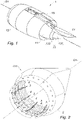
- FIG. 1 An aircraft propulsion assembly nacelle 1 is illustrated in figure 1 .
- This nacelle 1 comprises a reactor mast 11 and a turbofan type engine (not shown) housed in the nacelle 1.
- the reactor mast 11, partially shown, is intended to be fixed to a wing (not shown) or to the fuselage (not shown) of the aircraft.
- the nacelle comprises an air inlet 12 adapted to allow optimum capture towards the turbojet engine of the air necessary to supply a fan (not shown) and internal compressors (not shown) of the turbojet engine.
- the nacelle 1 extends along a longitudinal axis D1 shown coinciding with the axis of the engine.
- the nacelle 1 Under the pylon 11, downstream of the turbojet engine, the nacelle 1 comprises an exhaust nozzle 13 comprising an ejection cone 131 ("plug” in English) and a primary nozzle 132 ("nozzle" in English).
- the ejection cone 131 and the primary nozzle 132 of the exhaust nozzle 13 define a passage for a flow of hot air leaving the turbojet engine.
- the nacelle 1 further comprises an internal fixed structure 14 and an external structure 15 which define a passage for a flow of cold air from the turbojet engine.
- the invention relates to a structure capable of constituting all or part of one or more parts of the nacelle 1 such as the ejection cone 131 or the primary nozzle 132 of the exhaust nozzle 13.
- this structure is an ejection cone 131.
- the structure 131 comprises a first skin 2.
- This first skin 2 comprises an outer surface intended to be in contact with the flow of hot air leaving the turbojet engine.
- the structure comprises stiffeners 3.
- the stiffeners 3 form reinforcement bars which extend parallel to the longitudinal axis D1 and regularly spaced around the circumference of the ejection cone 131.
- stiffeners 3 extend here from an internal surface of the first skin 2, that is to say towards the inside of the ejection cone 131.
- the stiffeners 3 are fixed to the first skin 2.
- the stiffeners 3 can be added elements fixed to the first skin 2 by brazing or welding.
- the stiffeners 3 and the first skin 2 can be made in one piece, for example by draping fibrous plies on a mould.
- the number of stiffeners 3 should in particular be determined so as to ensure good vibratory and mechanical stability of the first skin 2, depending on the stresses to which the structure 131 will be subjected.
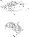
- the structure 131 further comprises acoustic treatment modules 4.
- each acoustic treatment module 4 comprises a cellular core 41 and a second skin 42 fixed to the cellular core 41.
- the alveolar core 41 comprises transverse foils forming cavities intended to constitute Helmholtz cavities.
- the geometry of these cavities can be adapted to manufacturing constraints and to the frequencies to be attenuated.
- each cavity is delimited by four foils and therefore has a quadrilateral section.
- the cavities may have a hexagonal section.
- the first skin 2 and the acoustic treatment modules 4 are arranged so that the cellular core 41 of each module 4 is sandwiched between the corresponding second skin 42 and the first skin 2.
- the second skin 42 is not shown on the 4 modules of the picture 3 : however, this arrangement emerges clearly from the figure 12 which shows an example of a structure according to the invention in cross section.
- each acoustic treatment module 4 is set between two respective stiffeners 3 (see picture 2 ).
- the stiffeners 3 also have the function of positioning and maintaining the acoustic treatment modules 4 in a fixed position relative to the first skin 2 at least in a tangential direction relative to the first skin 2.
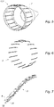
- the structure 131 comprises holding means 5.
- the holding means 5 comprise elastic strips 5 fixed to the stiffeners 3 by means of fixing means 51 of the rivet type (see figure 12 ).
- the holding means 5 comprise elastic strips 5 fixed to the stiffeners 3 by means of fixing means 51 of the rivet type (see figure 12 ).
- two elastic blades 5 can thus be fixed on each stiffener 3.
- each elastic blade 5 extends on either side of a stiffener 3 so as to bear against the second skin 42 of the acoustic treatment modules 4 located on either side of this stiffener 3 (see figure 12 ).
- each acoustic processing module 4 is simply supported on the first skin 2.
- the acoustic treatment modules 4 are freed from the structural constraints to which the first skin 2 is subjected.
- the modules 4 are intended to provide acoustic treatment to the nacelle 1.
- the first skin 2 is made acoustically permeable, for example using orifices (not shown) made in the first skin 2.
- orifices make it possible to capture and attenuate, within the cellular core of the modules 4, acoustic waves which propagate at the level of the external surface of the first skin 2.
- the attenuation of acoustic waves within the alveolar core of the modules 4 could be achieved by making the second skin 42 acoustically permeable, the first skin 2 being acoustically impermeable.
- the attenuated waves would be waves propagating at the level of an external surface of the second skin 42 of the modules 4.
- each stiffener 3 comprises a first element forming a stop for two adjacent acoustic treatment modules so as to limit the movement of these modules in a direction tangential to the first skin 2.
- Each stiffener 3 also comprises a second element 5 forming a stop for two adjacent acoustic treatment modules so as to limit the movement of these modules in a direction normal to the first skin 2.
- the second elements 5 of the stiffeners 3 thus constitute said holding means.
- the stiffeners 3 have a "T" section.
- the holding means 5 cooperate with the second skin 42 of each acoustic processing module 4 so as to exert a force to hold the modules 4 against the first skin 2.
- the stiffeners 3 extend in respective directions parallel to the longitudinal axis D1 of the nacelle 1 when the structure 131 (for example of the figure 2 ) is installed on platform 1 ( figure 1 ).
- the stiffeners 3 of the structure 131 can extend circumferentially around the longitudinal axis D1.
- acoustic treatment modules 4 are embedded between two stiffeners 3A and 3B.
- the retention of the acoustic treatment modules 4 can be achieved by any other appropriate technique, for example those described below.
- the stiffeners 3 have a "T" section as described above with reference to the figure 8 .
- the means 5 for holding the structure of the figure 13 include elastic blades 5 fixed on the stiffeners 3.
- the elastic blade 5A can be wrapped around the head of the stiffener 3 as shown in figure 13 (blade 5A on stiffener 3 on the left of the figure).
- the elastic blade 5A extends on either side of the stiffener 3 so as to bear against the second skin of the acoustic treatment modules 4 located on either side of this stiffener 3 to exert a effort to maintain the modules against the first skin (see figure 13 , stiffener 3 on the left).
- Another mode of holding consists in fixing the elastic blade 5B using fastening means 51 which can be bolts or rivets (blade 5B on the stiffener 3 to the right of the figure 13 ).
- the elastic blade 5B extends on one side of the stiffener 3 so as to bear against the second skin of the acoustic treatment module 4 located on this side of the stiffener 3 (see figure 13 , stiffener 3 on the right).
- the holding means comprise transverse elastic elements 6 arranged to exert transverse pressure on the acoustic treatment modules 4 against the first skin 2, so as to immobilize these modules in a direction normal to the first skin.
- each transverse elastic element 6 covers the second skin of an acoustic treatment module 4 so as to be in contact on the one hand with a part of the stiffeners 3 facing this module 4 and other with the second skin of this module 4.
- the transverse elastic elements 6 can be corrugated so as to exert a force for maintaining the modules 4 against the first skin 2 by several contact zones spaced from each other.
- the figures 15 to 18 show holding means comprising lateral elastic elements arranged to exert a lateral pressure of the acoustic treatment modules 4 against the respective stiffeners 3 between which these modules 4 are embedded, so as to immobilize these modules 4 in a direction tangential to the first skin 2.
- the lateral elastic elements 421 and 422 are formed by the second skin 42 of the acoustic treatment modules 4, in particular by protrusions of the second skin 42 folded.
- the lateral elastic elements 411 are formed by the cellular core 41 of the acoustic treatment modules 4, in particular by end folds of the transverse partitions of the cellular core.
- a lateral elastic element 7 can consist of a corrugated foil and/or can be placed between the cellular core 41 of an acoustic treatment module and a corresponding stiffener 3.
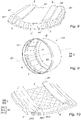
- FIG. 5 Another example of a structure 131 of the ejection cone type is illustrated in figures 5 to 7 .
- each stiffener 3 comprises a first element 31 forming a stop for an acoustic treatment module 4 so as to limit the movement of this module 4 in a direction tangential to the first skin 2.
- Each stiffener 3 further comprises a second element 5 forming a stop for an acoustic treatment module so as to limit the movement of this module in a direction normal to the first skin 2.
- the second elements 5 of these stiffeners 3 thus constitute part of said holding means.
- the holding of the acoustic treatment modules 4 can be supplemented by at least one holding device as presented for example in figure 13 .
- the structure of the embodiment of the figures 5 to 7 may include elastic elements as illustrated in figures 14 to 18 to maintain pressure in the module between stiffeners.
- such a stiffener 3 also comprises a third element 32 which can be embedded in the first skin 2 or which can form part of the first skin 2.
- the structure 131 comprises a set of longitudinal stiffeners positioned along meridians or geodesic lines of the aerodynamic surface 2 of the structure 131. This arrangement associated with a number of stiffeners distributed regularly around the circumference is particularly well suited to enhance the modes own hull of the tonnoid part of the structure.
- the structure 131 may also comprise a circumferential stiffener or substantially perpendicular to the longitudinal stiffeners 3.
- This circumferential stiffener can have a "T” or “ ⁇ ” section allowing a possible partial maintenance of the acoustic treatment modules 4, and further increasing the effectiveness of all the longitudinal stiffeners to the increase of the natural modes of structure.
- the first skin 2 and the stiffeners 3 can be made from a composite material with a ceramic matrix, and the acoustic treatment modules 4 from a metallic material such as titanium or a nickel-based alloy.
- the structure can be used to form other parts of the nacelle such as the primary nozzle of an exhaust nozzle.
Landscapes
- Engineering & Computer Science (AREA)
- Chemical & Material Sciences (AREA)
- Combustion & Propulsion (AREA)
- Mechanical Engineering (AREA)
- General Engineering & Computer Science (AREA)
- Aviation & Aerospace Engineering (AREA)
- Structures Of Non-Positive Displacement Pumps (AREA)
- Wind Motors (AREA)
- Soundproofing, Sound Blocking, And Sound Damping (AREA)
Claims (13)
- Struktur (131) für die Gondel (1) eines Triebwerks eines Flugzeugs, umfassend eine erste Haut (2), an der ersten Haut befestigte Versteifungen (3) zum Versteifen dieser ersten Haut (2) und akustische Behandlungsmodule (4), wobei jedes akustische Behandlungsmodul (4) einen Wabenkern (41) und eine am Wabenkern (41) befestigte zweite Haut (42) umfasst, wobei die erste Haut (2) und die akustischen Behandlungsmodule (4) so angeordnet sind, dass der Wabenkern (41) jedes Moduls (4) zwischen der entsprechenden zweiten Haut (42) und der ersten Haut (2) eingeschlossen ist, wobei die erste Haut (2) oder die zweite Haut (42) der akustischen Behandlungsmodule (4) akustisch durchlässig sind, um die Stärke der akustischen Wellen im Wabenkern (41) der Module (4) zu dämpfen, wobei diese Struktur (131) so ist, dass jedes akustische Behandlungsmodul (4) zwischen mindestens zwei jeweiligen Versteifungen (3) eingeschlossen ist, so dass jedes akustische Behandlungsmodul (4) einfach an der ersten Haut (2) aufliegt, und so dass sie Haltemittel (5, 3A2, 5A, 5B) zum Halten jedes akustischen Behandlungselements (4) gegen die erste Haut (2) umfasst.
- Struktur nach Anspruch 1, wobei die Haltemittel (5) mit der zweiten Haut (42) jedes akustischen Behandlungsmoduls (4) so zusammenwirken, dass sie eine Haltekraft der Module (4) gegen die erste Haut (2) ausüben.
- Struktur nach Anspruch 1 oder 2, wobei jede Versteifung (3) ein erstes Element (3A1), das einen Anschlag für ein oder mehrere akustische Behandlungselemente (4) bildet, um die Verschiebung dieses oder dieser Module (4) entlang einer Tangentialrichtung an der ersten Haut (2) zu begrenzen, und ein zweites Element (3A2), das einen Anschlag für ein oder mehrere akustische Behandlungselemente (4) bildet, um die Verschiebung dieses oder dieser Module (4) entlang einer Normalenrichtung an der ersten Haut (2) zu begrenzen, umfasst, wobei dieses zweite Element (3A2) mindestens einen Teil der Haltemittel darstellt.
- Struktur nach einem der Ansprüche 1 bis 3, wobei die Versteifungen (3) mindestens einen Teil der Haltemittel (5, 3A2) darstellen.
- Struktur nach einem der Ansprüche 1 bis 4, wobei die Haltemittel elastische Lamellen (5, 5A, 5B) umfassen, die an den Versteifungen (3) befestigt sind.
- Struktur nach einem der Ansprüche 1 bis 5, wobei die Haltemittel ein oder mehrere elastische Lateralelemente (421, 422, 411, 7) umfassen, die angeordnet sind, um einen Lateraldruck der akustischen Behandlungsmodule (4) gegen die jeweiligen Versteifungen (3) auszuüben, zwischen denen diese Module (4) eingefasst sind, um diese Module (4) entlang einer Tangentialrichtung an der ersten Haut (2) anzuhalten.
- Struktur nach einem der Ansprüche 1 bis 6, wobei die Haltemittel ein oder mehrere elastische Transversalelemente (6) umfassen, die angeordnet sind, um eine Transversaldruck der akustischen Behandlungsmodule (4) gegen die erste Haut (2) auszuüben, um diese Module (4) entlang einer Normalenrichtung an der ersten Haut (2) anzuhalten.
- Struktur nach Anspruch 6 oder 7, wobei die elastischen Lateralelemente (421, 422, 411) oder Transversalelemente von der zweiten Haut (42) und/oder vom Wabenkern (41) der akustischen Behandlungsmodule (4) gebildet werden.
- Struktur nach einem der Ansprüche 1 bis 8, wobei die erste Haut (2) und die Versteifungen (3) einen keramischen Matrix-Verbundwerkstoff umfassen.
- Struktur nach einem der Ansprüche 1 bis 9, wobei die akustischen Behandlungsmodule (4) ein metallisches Material wie Titan oder eine nickelbasierte Legierung umfassen.
- Austrittsdüse (13) der Gondel (1) des Flugzeugtriebwerks, dadurch gekennzeichnet, dass sie eine Struktur (131) nach einem der Ansprüche 1 bis 10 umfasst.
- Gondel (1) des Flugzeugtriebwerks, dadurch gekennzeichnet, dass sie eine Struktur (131) nach einem der Ansprüche 1 bis 10 oder eine Austrittsdüse (13) nach Anspruch 11 umfasst.
- Gondel (1) nach Anspruch 12, wobei die Versteifungen (3) der Struktur sich entlang jeweiliger Richtungen erstrecken, die parallel zu einer Längsachse (D1) der Gondel (1) sind.
Applications Claiming Priority (2)
| Application Number | Priority Date | Filing Date | Title |
|---|---|---|---|
| FR1850079A FR3076544B1 (fr) | 2018-01-05 | 2018-01-05 | Structure de traitement acoustique pour nacelle d’ensemble propulsif d’aeronef |
| PCT/FR2019/050018 WO2019135058A1 (fr) | 2018-01-05 | 2019-01-04 | Structure de traitement acoustique pour nacelle d'ensemble propulsif d'aéronef |
Publications (2)
| Publication Number | Publication Date |
|---|---|
| EP3735378A1 EP3735378A1 (de) | 2020-11-11 |
| EP3735378B1 true EP3735378B1 (de) | 2022-08-17 |
Family
ID=61521743
Family Applications (1)
| Application Number | Title | Priority Date | Filing Date |
|---|---|---|---|
| EP19703148.7A Active EP3735378B1 (de) | 2018-01-05 | 2019-01-04 | Akustische behandlungsstruktur für die gondel eines triebwerks eines flugzeugs |
Country Status (4)
| Country | Link |
|---|---|
| US (1) | US11512666B2 (de) |
| EP (1) | EP3735378B1 (de) |
| FR (1) | FR3076544B1 (de) |
| WO (1) | WO2019135058A1 (de) |
Families Citing this family (5)
| Publication number | Priority date | Publication date | Assignee | Title |
|---|---|---|---|---|
| FR3068007B1 (fr) * | 2017-06-23 | 2021-07-16 | Safran Nacelles | Dispositif de traitement acoustique pour nacelle de turboreacteur d'aeronef |
| US11315538B2 (en) * | 2017-12-13 | 2022-04-26 | The Boeing Company | Anti-resonant panels |
| CN112984768B (zh) * | 2021-03-17 | 2024-08-30 | 马鞍山迈安特航空制造有限公司 | 降噪结构 |
| US11879395B2 (en) * | 2021-05-03 | 2024-01-23 | The Boeing Company | Noise attenuation in an engine nacelle |
| FR3124828B1 (fr) | 2021-07-01 | 2023-05-26 | Safran Power Units | Pièce mécanique amovible d’isolation acoustique d’un carter d’entrée d’air |
Family Cites Families (7)
| Publication number | Priority date | Publication date | Assignee | Title |
|---|---|---|---|---|
| US4235303A (en) * | 1978-11-20 | 1980-11-25 | The Boeing Company | Combination bulk absorber-honeycomb acoustic panels |
| US4384634A (en) * | 1979-12-18 | 1983-05-24 | United Technologies Corporation | Sound absorbing structure |
| US5594216A (en) * | 1994-11-29 | 1997-01-14 | Lockheed Missiles & Space Co., Inc. | Jet engine sound-insulation structure |
| CA2731974A1 (fr) * | 2008-07-30 | 2010-02-04 | Aircelle | Panneau d'attenuation acoustique pour nacelle de moteur d'aeronef |
| FR2934641B1 (fr) * | 2008-07-30 | 2011-03-04 | Aircelle Sa | Panneau d'attenuation acoustique pour nacelle de moteur d'aeronef |
| FR3033839B1 (fr) * | 2015-03-16 | 2018-09-28 | Safran Aircraft Engines | Ensemble pour turbomachine d'aeronef comprenant un carter de soufflante equipe d'un revetement acoustique integrant un raidisseur de carter de soufflante |
| FR3041937B1 (fr) * | 2015-10-05 | 2017-10-20 | Airbus Operations Sas | Structure compartimentee pour le traitement acoustique et le degivrage d'une nacelle d'aeronef et nacelle d'aeronef incorporant ladite structure |
-
2018
- 2018-01-05 FR FR1850079A patent/FR3076544B1/fr active Active
-
2019
- 2019-01-04 EP EP19703148.7A patent/EP3735378B1/de active Active
- 2019-01-04 WO PCT/FR2019/050018 patent/WO2019135058A1/fr not_active Ceased
-
2020
- 2020-07-06 US US16/921,163 patent/US11512666B2/en active Active
Also Published As
| Publication number | Publication date |
|---|---|
| WO2019135058A1 (fr) | 2019-07-11 |
| EP3735378A1 (de) | 2020-11-11 |
| US11512666B2 (en) | 2022-11-29 |
| US20200339243A1 (en) | 2020-10-29 |
| FR3076544B1 (fr) | 2020-01-31 |
| FR3076544A1 (fr) | 2019-07-12 |
Similar Documents
| Publication | Publication Date | Title |
|---|---|---|
| EP3735378B1 (de) | Akustische behandlungsstruktur für die gondel eines triebwerks eines flugzeugs | |
| EP2723642B1 (de) | Aufhängestruktur einer turbomaschine | |
| EP2473727A1 (de) | Strukturierungsanordnung für eine abgasdüse | |
| EP2318683A2 (de) | Schalldämpfungsplatte für luftfahrzeugmotorgondel | |
| FR2956876A1 (fr) | Module structural et aerodynamique d'un carter de turbomachine et structure de carter comportant une pluralite d'un tel module | |
| EP3673163B1 (de) | Zellstruktur und schalldämpfungsvorrichtung für eine gondel einer flugzeugantriebsanordnung | |
| FR3048957A1 (fr) | Ensemble moteur pour aeronef, comprenant des dispositifs souples de transmission d'efforts agences entre les capots d'inversion de poussee et le moteur | |
| CA2905793A1 (fr) | Turbomachine, telle qu'un turboreacteur ou un turbopropulseur d'avion | |
| EP3587274A1 (de) | Gondel einer antriebseinheit eines luftfahrzeugs, die eine vielzahl von dämpfungselementen zwischen einem vorderteil und einem hauptteil umfasst, und entsprechende antriebseinhait eines luftfahrzeugs | |
| FR2956875A1 (fr) | Aube allegee pour turbomachine, carter comportant une pluralite d'une telle aube et turbomachine comportant au moins un tel carter | |
| WO2013024216A1 (fr) | Cône d'éjection pour turboréacteur d'aéronef | |
| EP3831719B1 (de) | Rückwärtige verkleidung einer motorsäule eines luftfahrzeugs mit mehrschichtigem wärmeschutzschild | |
| FR3095369A1 (fr) | Procédé de fabrication d’une structure d’absorption acoustique utilisant au moins une plaque de conformation, structure d’absorption acoustique obtenue à partir dudit procédé et aéronef comprenant ladite structure d’absorption acoustique | |
| WO2016181073A1 (fr) | Panneau composite et nacelle de turboréacteur d'aéronef comprenant un tel panneau | |
| FR2938014A1 (fr) | Panneau d'attenuation acoustique pour nacelle de moteur d'aeronef | |
| EP2415117B1 (de) | Funkantenne mit verbessertem versteifungsmittel | |
| FR3016159A1 (fr) | Nacelle de turboreacteur d'aeronef comprenant un ensemble d'entree d'air a rigidite augmentee | |
| EP4028656B1 (de) | Strukturelle und/oder akustische platte mit einem zur innenseite der platte gerichteten u-förmigen dichtungsflansch und verfahren zur herstellung einer solchen platte | |
| WO2016092238A1 (fr) | Procédé pour la réparation d'un panneau acoustique en matériau composite | |
| WO2015001258A1 (fr) | Procédé de réparation d'un panneau par application d'un doubleur | |
| FR2944470A1 (fr) | Panneau alveolaire | |
| FR3151297A3 (fr) | Sous structure arrière de mât moteur |
Legal Events
| Date | Code | Title | Description |
|---|---|---|---|
| STAA | Information on the status of an ep patent application or granted ep patent |
Free format text: STATUS: UNKNOWN |
|
| STAA | Information on the status of an ep patent application or granted ep patent |
Free format text: STATUS: THE INTERNATIONAL PUBLICATION HAS BEEN MADE |
|
| PUAI | Public reference made under article 153(3) epc to a published international application that has entered the european phase |
Free format text: ORIGINAL CODE: 0009012 |
|
| STAA | Information on the status of an ep patent application or granted ep patent |
Free format text: STATUS: REQUEST FOR EXAMINATION WAS MADE |
|
| 17P | Request for examination filed |
Effective date: 20200721 |
|
| AK | Designated contracting states |
Kind code of ref document: A1 Designated state(s): AL AT BE BG CH CY CZ DE DK EE ES FI FR GB GR HR HU IE IS IT LI LT LU LV MC MK MT NL NO PL PT RO RS SE SI SK SM TR |
|
| AX | Request for extension of the european patent |
Extension state: BA ME |
|
| DAV | Request for validation of the european patent (deleted) | ||
| DAX | Request for extension of the european patent (deleted) | ||
| GRAP | Despatch of communication of intention to grant a patent |
Free format text: ORIGINAL CODE: EPIDOSNIGR1 |
|
| STAA | Information on the status of an ep patent application or granted ep patent |
Free format text: STATUS: GRANT OF PATENT IS INTENDED |
|
| INTG | Intention to grant announced |
Effective date: 20220329 |
|
| GRAS | Grant fee paid |
Free format text: ORIGINAL CODE: EPIDOSNIGR3 |
|
| GRAA | (expected) grant |
Free format text: ORIGINAL CODE: 0009210 |
|
| STAA | Information on the status of an ep patent application or granted ep patent |
Free format text: STATUS: THE PATENT HAS BEEN GRANTED |
|
| AK | Designated contracting states |
Kind code of ref document: B1 Designated state(s): AL AT BE BG CH CY CZ DE DK EE ES FI FR GB GR HR HU IE IS IT LI LT LU LV MC MK MT NL NO PL PT RO RS SE SI SK SM TR |
|
| REG | Reference to a national code |
Ref country code: CH Ref legal event code: EP |
|
| REG | Reference to a national code |
Ref country code: DE Ref legal event code: R096 Ref document number: 602019018358 Country of ref document: DE |
|
| REG | Reference to a national code |
Ref country code: IE Ref legal event code: FG4D Free format text: LANGUAGE OF EP DOCUMENT: FRENCH |
|
| REG | Reference to a national code |
Ref country code: AT Ref legal event code: REF Ref document number: 1512012 Country of ref document: AT Kind code of ref document: T Effective date: 20220915 |
|
| REG | Reference to a national code |
Ref country code: NL Ref legal event code: MP Effective date: 20220817 |
|
| REG | Reference to a national code |
Ref country code: LT Ref legal event code: MG9D |
|
| PG25 | Lapsed in a contracting state [announced via postgrant information from national office to epo] |
Ref country code: SE Free format text: LAPSE BECAUSE OF FAILURE TO SUBMIT A TRANSLATION OF THE DESCRIPTION OR TO PAY THE FEE WITHIN THE PRESCRIBED TIME-LIMIT Effective date: 20220817 Ref country code: RS Free format text: LAPSE BECAUSE OF FAILURE TO SUBMIT A TRANSLATION OF THE DESCRIPTION OR TO PAY THE FEE WITHIN THE PRESCRIBED TIME-LIMIT Effective date: 20220817 Ref country code: PT Free format text: LAPSE BECAUSE OF FAILURE TO SUBMIT A TRANSLATION OF THE DESCRIPTION OR TO PAY THE FEE WITHIN THE PRESCRIBED TIME-LIMIT Effective date: 20221219 Ref country code: NO Free format text: LAPSE BECAUSE OF FAILURE TO SUBMIT A TRANSLATION OF THE DESCRIPTION OR TO PAY THE FEE WITHIN THE PRESCRIBED TIME-LIMIT Effective date: 20221117 Ref country code: NL Free format text: LAPSE BECAUSE OF FAILURE TO SUBMIT A TRANSLATION OF THE DESCRIPTION OR TO PAY THE FEE WITHIN THE PRESCRIBED TIME-LIMIT Effective date: 20220817 Ref country code: LV Free format text: LAPSE BECAUSE OF FAILURE TO SUBMIT A TRANSLATION OF THE DESCRIPTION OR TO PAY THE FEE WITHIN THE PRESCRIBED TIME-LIMIT Effective date: 20220817 Ref country code: LT Free format text: LAPSE BECAUSE OF FAILURE TO SUBMIT A TRANSLATION OF THE DESCRIPTION OR TO PAY THE FEE WITHIN THE PRESCRIBED TIME-LIMIT Effective date: 20220817 Ref country code: FI Free format text: LAPSE BECAUSE OF FAILURE TO SUBMIT A TRANSLATION OF THE DESCRIPTION OR TO PAY THE FEE WITHIN THE PRESCRIBED TIME-LIMIT Effective date: 20220817 |
|
| REG | Reference to a national code |
Ref country code: AT Ref legal event code: MK05 Ref document number: 1512012 Country of ref document: AT Kind code of ref document: T Effective date: 20220817 |
|
| PG25 | Lapsed in a contracting state [announced via postgrant information from national office to epo] |
Ref country code: PL Free format text: LAPSE BECAUSE OF FAILURE TO SUBMIT A TRANSLATION OF THE DESCRIPTION OR TO PAY THE FEE WITHIN THE PRESCRIBED TIME-LIMIT Effective date: 20220817 Ref country code: IS Free format text: LAPSE BECAUSE OF FAILURE TO SUBMIT A TRANSLATION OF THE DESCRIPTION OR TO PAY THE FEE WITHIN THE PRESCRIBED TIME-LIMIT Effective date: 20221217 Ref country code: HR Free format text: LAPSE BECAUSE OF FAILURE TO SUBMIT A TRANSLATION OF THE DESCRIPTION OR TO PAY THE FEE WITHIN THE PRESCRIBED TIME-LIMIT Effective date: 20220817 Ref country code: GR Free format text: LAPSE BECAUSE OF FAILURE TO SUBMIT A TRANSLATION OF THE DESCRIPTION OR TO PAY THE FEE WITHIN THE PRESCRIBED TIME-LIMIT Effective date: 20221118 |
|
| PG25 | Lapsed in a contracting state [announced via postgrant information from national office to epo] |
Ref country code: SM Free format text: LAPSE BECAUSE OF FAILURE TO SUBMIT A TRANSLATION OF THE DESCRIPTION OR TO PAY THE FEE WITHIN THE PRESCRIBED TIME-LIMIT Effective date: 20220817 Ref country code: RO Free format text: LAPSE BECAUSE OF FAILURE TO SUBMIT A TRANSLATION OF THE DESCRIPTION OR TO PAY THE FEE WITHIN THE PRESCRIBED TIME-LIMIT Effective date: 20220817 Ref country code: ES Free format text: LAPSE BECAUSE OF FAILURE TO SUBMIT A TRANSLATION OF THE DESCRIPTION OR TO PAY THE FEE WITHIN THE PRESCRIBED TIME-LIMIT Effective date: 20220817 Ref country code: DK Free format text: LAPSE BECAUSE OF FAILURE TO SUBMIT A TRANSLATION OF THE DESCRIPTION OR TO PAY THE FEE WITHIN THE PRESCRIBED TIME-LIMIT Effective date: 20220817 Ref country code: CZ Free format text: LAPSE BECAUSE OF FAILURE TO SUBMIT A TRANSLATION OF THE DESCRIPTION OR TO PAY THE FEE WITHIN THE PRESCRIBED TIME-LIMIT Effective date: 20220817 Ref country code: AT Free format text: LAPSE BECAUSE OF FAILURE TO SUBMIT A TRANSLATION OF THE DESCRIPTION OR TO PAY THE FEE WITHIN THE PRESCRIBED TIME-LIMIT Effective date: 20220817 |
|
| REG | Reference to a national code |
Ref country code: DE Ref legal event code: R097 Ref document number: 602019018358 Country of ref document: DE |
|
| PG25 | Lapsed in a contracting state [announced via postgrant information from national office to epo] |
Ref country code: SK Free format text: LAPSE BECAUSE OF FAILURE TO SUBMIT A TRANSLATION OF THE DESCRIPTION OR TO PAY THE FEE WITHIN THE PRESCRIBED TIME-LIMIT Effective date: 20220817 Ref country code: EE Free format text: LAPSE BECAUSE OF FAILURE TO SUBMIT A TRANSLATION OF THE DESCRIPTION OR TO PAY THE FEE WITHIN THE PRESCRIBED TIME-LIMIT Effective date: 20220817 |
|
| PLBE | No opposition filed within time limit |
Free format text: ORIGINAL CODE: 0009261 |
|
| STAA | Information on the status of an ep patent application or granted ep patent |
Free format text: STATUS: NO OPPOSITION FILED WITHIN TIME LIMIT |
|
| PG25 | Lapsed in a contracting state [announced via postgrant information from national office to epo] |
Ref country code: AL Free format text: LAPSE BECAUSE OF FAILURE TO SUBMIT A TRANSLATION OF THE DESCRIPTION OR TO PAY THE FEE WITHIN THE PRESCRIBED TIME-LIMIT Effective date: 20220817 |
|
| 26N | No opposition filed |
Effective date: 20230519 |
|
| PG25 | Lapsed in a contracting state [announced via postgrant information from national office to epo] |
Ref country code: SI Free format text: LAPSE BECAUSE OF FAILURE TO SUBMIT A TRANSLATION OF THE DESCRIPTION OR TO PAY THE FEE WITHIN THE PRESCRIBED TIME-LIMIT Effective date: 20220817 |
|
| REG | Reference to a national code |
Ref country code: CH Ref legal event code: PL |
|
| PG25 | Lapsed in a contracting state [announced via postgrant information from national office to epo] |
Ref country code: LU Free format text: LAPSE BECAUSE OF NON-PAYMENT OF DUE FEES Effective date: 20230104 |
|
| REG | Reference to a national code |
Ref country code: BE Ref legal event code: MM Effective date: 20230131 |
|
| PG25 | Lapsed in a contracting state [announced via postgrant information from national office to epo] |
Ref country code: LI Free format text: LAPSE BECAUSE OF NON-PAYMENT OF DUE FEES Effective date: 20230131 Ref country code: CH Free format text: LAPSE BECAUSE OF NON-PAYMENT OF DUE FEES Effective date: 20230131 |
|
| PG25 | Lapsed in a contracting state [announced via postgrant information from national office to epo] |
Ref country code: BE Free format text: LAPSE BECAUSE OF NON-PAYMENT OF DUE FEES Effective date: 20230131 |
|
| PG25 | Lapsed in a contracting state [announced via postgrant information from national office to epo] |
Ref country code: IE Free format text: LAPSE BECAUSE OF NON-PAYMENT OF DUE FEES Effective date: 20230104 |
|
| PG25 | Lapsed in a contracting state [announced via postgrant information from national office to epo] |
Ref country code: IT Free format text: LAPSE BECAUSE OF FAILURE TO SUBMIT A TRANSLATION OF THE DESCRIPTION OR TO PAY THE FEE WITHIN THE PRESCRIBED TIME-LIMIT Effective date: 20220817 |
|
| PG25 | Lapsed in a contracting state [announced via postgrant information from national office to epo] |
Ref country code: MC Free format text: LAPSE BECAUSE OF FAILURE TO SUBMIT A TRANSLATION OF THE DESCRIPTION OR TO PAY THE FEE WITHIN THE PRESCRIBED TIME-LIMIT Effective date: 20220817 |
|
| PG25 | Lapsed in a contracting state [announced via postgrant information from national office to epo] |
Ref country code: MC Free format text: LAPSE BECAUSE OF FAILURE TO SUBMIT A TRANSLATION OF THE DESCRIPTION OR TO PAY THE FEE WITHIN THE PRESCRIBED TIME-LIMIT Effective date: 20220817 |
|
| PG25 | Lapsed in a contracting state [announced via postgrant information from national office to epo] |
Ref country code: BG Free format text: LAPSE BECAUSE OF FAILURE TO SUBMIT A TRANSLATION OF THE DESCRIPTION OR TO PAY THE FEE WITHIN THE PRESCRIBED TIME-LIMIT Effective date: 20220817 |
|
| PG25 | Lapsed in a contracting state [announced via postgrant information from national office to epo] |
Ref country code: BG Free format text: LAPSE BECAUSE OF FAILURE TO SUBMIT A TRANSLATION OF THE DESCRIPTION OR TO PAY THE FEE WITHIN THE PRESCRIBED TIME-LIMIT Effective date: 20220817 |
|
| PG25 | Lapsed in a contracting state [announced via postgrant information from national office to epo] |
Ref country code: CY Free format text: LAPSE BECAUSE OF FAILURE TO SUBMIT A TRANSLATION OF THE DESCRIPTION OR TO PAY THE FEE WITHIN THE PRESCRIBED TIME-LIMIT; INVALID AB INITIO Effective date: 20190104 |
|
| PG25 | Lapsed in a contracting state [announced via postgrant information from national office to epo] |
Ref country code: HU Free format text: LAPSE BECAUSE OF FAILURE TO SUBMIT A TRANSLATION OF THE DESCRIPTION OR TO PAY THE FEE WITHIN THE PRESCRIBED TIME-LIMIT; INVALID AB INITIO Effective date: 20190104 |
|
| PG25 | Lapsed in a contracting state [announced via postgrant information from national office to epo] |
Ref country code: TR Free format text: LAPSE BECAUSE OF FAILURE TO SUBMIT A TRANSLATION OF THE DESCRIPTION OR TO PAY THE FEE WITHIN THE PRESCRIBED TIME-LIMIT Effective date: 20220817 |
|
| PGFP | Annual fee paid to national office [announced via postgrant information from national office to epo] |
Ref country code: GB Payment date: 20260122 Year of fee payment: 8 |
|
| PGFP | Annual fee paid to national office [announced via postgrant information from national office to epo] |
Ref country code: DE Payment date: 20260120 Year of fee payment: 8 |
|
| PGFP | Annual fee paid to national office [announced via postgrant information from national office to epo] |
Ref country code: FR Payment date: 20260128 Year of fee payment: 8 |