EP3735185B1 - Fastener for holding a constricting cord in a reduced-diameter state around a cardiac valve annulus, and installation of the fastener - Google Patents
Fastener for holding a constricting cord in a reduced-diameter state around a cardiac valve annulus, and installation of the fastener Download PDFInfo
- Publication number
- EP3735185B1 EP3735185B1 EP18834304.0A EP18834304A EP3735185B1 EP 3735185 B1 EP3735185 B1 EP 3735185B1 EP 18834304 A EP18834304 A EP 18834304A EP 3735185 B1 EP3735185 B1 EP 3735185B1
- Authority
- EP
- European Patent Office
- Prior art keywords
- cord
- fastener
- cutting element
- opening
- shelf
- Prior art date
- Legal status (The legal status is an assumption and is not a legal conclusion. Google has not performed a legal analysis and makes no representation as to the accuracy of the status listed.)
- Active
Links
Images









Classifications
-
- A—HUMAN NECESSITIES
- A61—MEDICAL OR VETERINARY SCIENCE; HYGIENE
- A61B—DIAGNOSIS; SURGERY; IDENTIFICATION
- A61B17/00—Surgical instruments, devices or methods
- A61B17/04—Surgical instruments, devices or methods for suturing wounds; Holders or packages for needles or suture materials
- A61B17/0401—Suture anchors, buttons or pledgets, i.e. means for attaching sutures to bone, cartilage or soft tissue; Instruments for applying or removing suture anchors
-
- A—HUMAN NECESSITIES
- A61—MEDICAL OR VETERINARY SCIENCE; HYGIENE
- A61F—FILTERS IMPLANTABLE INTO BLOOD VESSELS; PROSTHESES; DEVICES PROVIDING PATENCY TO, OR PREVENTING COLLAPSING OF, TUBULAR STRUCTURES OF THE BODY, e.g. STENTS; ORTHOPAEDIC, NURSING OR CONTRACEPTIVE DEVICES; FOMENTATION; TREATMENT OR PROTECTION OF EYES OR EARS; BANDAGES, DRESSINGS OR ABSORBENT PADS; FIRST-AID KITS
- A61F2/00—Filters implantable into blood vessels; Prostheses, i.e. artificial substitutes or replacements for parts of the body; Appliances for connecting them with the body; Devices providing patency to, or preventing collapsing of, tubular structures of the body, e.g. stents
- A61F2/02—Prostheses implantable into the body
- A61F2/24—Heart valves ; Vascular valves, e.g. venous valves; Heart implants, e.g. passive devices for improving the function of the native valve or the heart muscle; Transmyocardial revascularisation [TMR] devices; Valves implantable in the body
- A61F2/2442—Annuloplasty rings or inserts for correcting the valve shape; Implants for improving the function of a native heart valve
-
- A—HUMAN NECESSITIES
- A61—MEDICAL OR VETERINARY SCIENCE; HYGIENE
- A61B—DIAGNOSIS; SURGERY; IDENTIFICATION
- A61B17/00—Surgical instruments, devices or methods
- A61B17/04—Surgical instruments, devices or methods for suturing wounds; Holders or packages for needles or suture materials
- A61B17/0467—Instruments for cutting sutures
-
- A—HUMAN NECESSITIES
- A61—MEDICAL OR VETERINARY SCIENCE; HYGIENE
- A61B—DIAGNOSIS; SURGERY; IDENTIFICATION
- A61B17/00—Surgical instruments, devices or methods
- A61B17/04—Surgical instruments, devices or methods for suturing wounds; Holders or packages for needles or suture materials
- A61B17/0487—Suture clamps, clips or locks, e.g. for replacing suture knots; Instruments for applying or removing suture clamps, clips or locks
-
- A—HUMAN NECESSITIES
- A61—MEDICAL OR VETERINARY SCIENCE; HYGIENE
- A61F—FILTERS IMPLANTABLE INTO BLOOD VESSELS; PROSTHESES; DEVICES PROVIDING PATENCY TO, OR PREVENTING COLLAPSING OF, TUBULAR STRUCTURES OF THE BODY, e.g. STENTS; ORTHOPAEDIC, NURSING OR CONTRACEPTIVE DEVICES; FOMENTATION; TREATMENT OR PROTECTION OF EYES OR EARS; BANDAGES, DRESSINGS OR ABSORBENT PADS; FIRST-AID KITS
- A61F2/00—Filters implantable into blood vessels; Prostheses, i.e. artificial substitutes or replacements for parts of the body; Appliances for connecting them with the body; Devices providing patency to, or preventing collapsing of, tubular structures of the body, e.g. stents
- A61F2/02—Prostheses implantable into the body
- A61F2/24—Heart valves ; Vascular valves, e.g. venous valves; Heart implants, e.g. passive devices for improving the function of the native valve or the heart muscle; Transmyocardial revascularisation [TMR] devices; Valves implantable in the body
- A61F2/2442—Annuloplasty rings or inserts for correcting the valve shape; Implants for improving the function of a native heart valve
- A61F2/2445—Annuloplasty rings in direct contact with the valve annulus
-
- A—HUMAN NECESSITIES
- A61—MEDICAL OR VETERINARY SCIENCE; HYGIENE
- A61F—FILTERS IMPLANTABLE INTO BLOOD VESSELS; PROSTHESES; DEVICES PROVIDING PATENCY TO, OR PREVENTING COLLAPSING OF, TUBULAR STRUCTURES OF THE BODY, e.g. STENTS; ORTHOPAEDIC, NURSING OR CONTRACEPTIVE DEVICES; FOMENTATION; TREATMENT OR PROTECTION OF EYES OR EARS; BANDAGES, DRESSINGS OR ABSORBENT PADS; FIRST-AID KITS
- A61F2/00—Filters implantable into blood vessels; Prostheses, i.e. artificial substitutes or replacements for parts of the body; Appliances for connecting them with the body; Devices providing patency to, or preventing collapsing of, tubular structures of the body, e.g. stents
- A61F2/02—Prostheses implantable into the body
- A61F2/24—Heart valves ; Vascular valves, e.g. venous valves; Heart implants, e.g. passive devices for improving the function of the native valve or the heart muscle; Transmyocardial revascularisation [TMR] devices; Valves implantable in the body
- A61F2/2442—Annuloplasty rings or inserts for correcting the valve shape; Implants for improving the function of a native heart valve
- A61F2/2466—Delivery devices therefor
-
- A—HUMAN NECESSITIES
- A61—MEDICAL OR VETERINARY SCIENCE; HYGIENE
- A61B—DIAGNOSIS; SURGERY; IDENTIFICATION
- A61B17/00—Surgical instruments, devices or methods
- A61B2017/00743—Type of operation; Specification of treatment sites
- A61B2017/00778—Operations on blood vessels
- A61B2017/00783—Valvuloplasty
-
- A—HUMAN NECESSITIES
- A61—MEDICAL OR VETERINARY SCIENCE; HYGIENE
- A61B—DIAGNOSIS; SURGERY; IDENTIFICATION
- A61B17/00—Surgical instruments, devices or methods
- A61B17/04—Surgical instruments, devices or methods for suturing wounds; Holders or packages for needles or suture materials
- A61B17/0487—Suture clamps, clips or locks, e.g. for replacing suture knots; Instruments for applying or removing suture clamps, clips or locks
- A61B2017/0488—Instruments for applying suture clamps, clips or locks
-
- A—HUMAN NECESSITIES
- A61—MEDICAL OR VETERINARY SCIENCE; HYGIENE
- A61F—FILTERS IMPLANTABLE INTO BLOOD VESSELS; PROSTHESES; DEVICES PROVIDING PATENCY TO, OR PREVENTING COLLAPSING OF, TUBULAR STRUCTURES OF THE BODY, e.g. STENTS; ORTHOPAEDIC, NURSING OR CONTRACEPTIVE DEVICES; FOMENTATION; TREATMENT OR PROTECTION OF EYES OR EARS; BANDAGES, DRESSINGS OR ABSORBENT PADS; FIRST-AID KITS
- A61F2220/00—Fixations or connections for prostheses classified in groups A61F2/00 - A61F2/26 or A61F2/82 or A61F9/00 or A61F11/00 or subgroups thereof
- A61F2220/0025—Connections or couplings between prosthetic parts, e.g. between modular parts; Connecting elements
- A61F2220/0033—Connections or couplings between prosthetic parts, e.g. between modular parts; Connecting elements made by longitudinally pushing a protrusion into a complementary-shaped recess, e.g. held by friction fit
-
- F—MECHANICAL ENGINEERING; LIGHTING; HEATING; WEAPONS; BLASTING
- F16—ENGINEERING ELEMENTS AND UNITS; GENERAL MEASURES FOR PRODUCING AND MAINTAINING EFFECTIVE FUNCTIONING OF MACHINES OR INSTALLATIONS; THERMAL INSULATION IN GENERAL
- F16G—BELTS, CABLES, OR ROPES, PREDOMINANTLY USED FOR DRIVING PURPOSES; CHAINS; FITTINGS PREDOMINANTLY USED THEREFOR
- F16G11/00—Means for fastening cables or ropes to one another or to other objects; Caps or sleeves for fixing on cables or ropes
- F16G11/10—Quick-acting fastenings; Clamps holding in one direction only
- F16G11/101—Quick-acting fastenings; Clamps holding in one direction only deforming the cable by moving a part of the fastener
-
- F—MECHANICAL ENGINEERING; LIGHTING; HEATING; WEAPONS; BLASTING
- F16—ENGINEERING ELEMENTS AND UNITS; GENERAL MEASURES FOR PRODUCING AND MAINTAINING EFFECTIVE FUNCTIONING OF MACHINES OR INSTALLATIONS; THERMAL INSULATION IN GENERAL
- F16G—BELTS, CABLES, OR ROPES, PREDOMINANTLY USED FOR DRIVING PURPOSES; CHAINS; FITTINGS PREDOMINANTLY USED THEREFOR
- F16G11/00—Means for fastening cables or ropes to one another or to other objects; Caps or sleeves for fixing on cables or ropes
- F16G11/14—Devices or coupling-pieces designed for easy formation of adjustable loops, e.g. choker hooks; Hooks or eyes with integral parts designed to facilitate quick attachment to cables or ropes at any point, e.g. by forming loops
Definitions
- the prior art approaches for tying a knot adjacent to the annulus were time-consuming and labor-intensive; the prior art crimp-based fasteners had to be relatively large in order to exert enough force on the cord to prevent slippage reliably; and the prior art approaches for cutting the cord were labor-intensive.
- US 2013/296889 A1 discloses another system and associated method for manipulating tissues and anatomical or other structures in medical applications for the purpose of treating diseases or disorders or other purposes, wherein the system includes a delivery device configured to deploy and implant anchor devices for such purposes.
- DE 695 12 446 T2 discloses an apparatus, comprising a handle assembly, and elongated housing extending distally from the handle assembly and a tool assembly detachably connected to a distal end of the body portion and remotely operable from the handle, wherein the tool assembly enables a surgeon to compress and maintain a securing member upon suture material in a body cavity and also provides means to cut unsecured suture material which extends from the compressed securing member.
- the present invention is defined by an apparatus for reducing a diameter of a cord according to claim 1. Further advantageous embodiments are described in the dependent claims.
- An aspect of the invention is thus directed to an apparatus for reducing a diameter of a cord that has been previously affixed to an annulus.
- the apparatus comprises a housing having a distal portion and a distal end.
- the apparatus also comprises a shelf positioned in the distal portion of the housing that extends in a distal-to-proximal direction, the shelf having an upper surface, a lower surface, and a shelf opening that runs between the upper and lower surfaces of the shelf.
- the apparatus also comprises a cutting element positioned above the shelf and arranged so that the cutting element can slide in the distal-to-proximal direction with respect to the shelf, the cutting element having a flat body with an upper surface, a lower surface, and an opening that passes between the upper and lower surfaces of the cutting element, the opening of the cutting element having (a) a proximal portion that is dimensioned so that two segments of the cord can slide freely through the proximal portion and (b) a slit shaped distal portion with sharp edges, wherein the slit shaped distal portion is oriented in the distal-to-proximal direction.
- the apparatus also comprises a fastener positioned at the distal end of the housing, the fastener having an opening. The fastener is movable from a first state in which the cord is free to slide through the opening in the fastener to a second state in which the cord is locked in place.
- the fastener, the shelf, and the cutting element are configured such that the cord can be threaded through the opening in the fastener when the fastener is in the first state so that that after the fastener is moved to the second state, the cord will be arranged in a pre-cutting position in which the cord passes above a portion of the cutting element that is distally beyond the opening of the cutting element, and then passes through the opening of the cutting element and through the opening in the shelf.
- the cutting element is configured such that when the cord is arranged in the pre-cutting position, movement of the cutting element in the proximal direction will cause the slit shaped distal portion of the opening of the cutting element to move in a proximal direction until the slit shaped distal portion reaches the cord and cuts the cord.
- Some embodiments of the apparatus further comprise a shaft that runs in the distal-to-proximal direction.
- the shaft is affixed to the cutting element so that pulling the shaft in a proximal direction will pull the cutting element in a proximal direction.
- the upper surface of the shelf lines up with the upper surface of the fastener so that the upper surface of the fastener extends a sliding platform provided by the shelf.
- the cutting element is configured to slide over both the shelf and a portion of the upper surface of the fastener.
- the distal end of the shelf has a first aligning feature (e.g., a notch), and the proximal end of the fastener has a second aligning feature (e.g., a protrusion) that matches the first aligning feature.
- the opening of the cutting element tapers down smoothly in a distal direction from the proximal portion of the opening of the cutting element towards the slit shaped distal portion of the opening of the cutting element.
- the slit shaped distal portion is formed by laser cutting the flat body of the cutting element to form a first slit having a width of 20-30 ⁇ m, and subsequently swaging the edges of the first slit towards each other to reduce the width of the first slit.
- an implant that includes the distal loop portion of a constricting cord can be affixed to an annulus of a cardiac valve or another anatomic annulus. After a sufficiently strong bond is achieved between the implant and the annulus, constricting the cord will reduce the diameter of the annulus.
- Some preferred embodiments of the implant rely on tissue ingrowth to strengthen the bond between the implant and the annulus.
- the constricting step is not performed immediately after the implant has been implanted. Instead, a significant waiting period (e.g., 1-3 months) elapses between the implantation step and the constricting step, in order to allow sufficient time for ingrowth to occur.
- tissue ingrowth of the adjacent soft tissue into the implant strengthens the bond between the implant and the annulus.
- the constricting cord is constricted so as to reduce the diameter of the annulus.
- the attachment mechanism of the implant may be sufficiently strong to withstand constricting immediately after the implant has been implanted, in which case the constricting cord may be constricted immediately after the implant is implanted.
- proximal portions (or segments) of the constricting cord run from outside the patient's body to the implanted distal loop portion of the constricting cord.
- constriction of the constricting cord may be implemented by sliding a push-tube down over the proximal portions of the constricting cord until the distal end of the push-tube arrives at the distal loop portion of the constricting cord (i.e., the loop-shaped portion which has been affixed to the annulus). Because the proximal portions of the constricting cord extend through the patient's vasculature between the constricting implant and an exit point, those proximal portions can serve as a guide wire over which the push-tube can be guided to its destination.
- the push-tube arrives at the distal loop portion of the constricting cord and is pushed in a distal direction, pulling the proximal portions of the constricting cord in a proximal direction will constrict the annulus, thereby reducing the circumference of the annulus.
- the distal ends of the proximal portions of the constricting cord are then fastened together to prevent the annulus from expanding again.
- the proximal portions of the constricting cord can then be clipped at a point that is proximal to the place where they are fastened together.
- FIG. 1A depicts the two primary components of a fastener 100/200 that may be used to fasten the distal ends of the proximal portions of the constricting cord together. More specifically, the two primary components of the fastener are the housing 100 and the sliding member 200.
- FIG. 1B depicts a side view of the housing 100 as viewed from a point that is distally beyond the distal end of the housing 100.
- the housing has an upper wall 102 and a lower wall 104 with a channel 110 disposed between the upper wall 102 and the lower wall 104.
- the channel 110 has a distal end 112.
- the upper wall 102 and the lower wall 104 are both flat and are parallel to each other; and the housing also has sidewalls 106 that run between the upper wall 102 and the lower wall 104 to form a rigid structure.
- the sidewalls 106 are also flat and parallel to each other.
- an extension portion 104X of the lower wall 104 extends distally beyond the distal end of the channel 112.
- This extension portion 104X has an opening 120.
- the area of this opening 120 is at least 0.4 mm 2 .
- the area of this opening 120 is between 0.3 and 1.0 mm 2 .
- Suitable materials for forming the housing 100 include cobalt chromium alloys (including but not limited to MP35N, L605, Elgiloy, etc.), surgical stainless steel (including but not limited to 305 ss, 316 ss, etc.), and other biocompatible metals.
- the housing 100 is dimensioned so that the channel 110 is 1.5 mm long (in a proximal-to-distal direction) 1.8 mm wide, and 0.64 mm tall; and so that the extension portion 104X extends 1.5 mm distally beyond the distal end of the channel 112.
- the sliding member 200 has an upper surface 202 and a lower surface 204 (shown in FIG. 3B ) and the sliding member 200 has an opening 220 that runs between the upper surface 202 and the lower surface 204.
- the area of this opening 220 is at least 0.4 mm 2 .
- the area of this opening 220 is between 0.3 and 1.0 mm 2 .
- the opening 220 has a distal end.
- the edges of the channel 110 of the housing and the opening 220 of the sliding member are not sharp, to reduce the chance of damaging the cord.
- Suitable materials for forming the sliding member 200 include any of the materials listed above in connection with the housing 100.
- the sliding member 200 is 4.6 mm long (in a proximal-to-distal direction), 0.53 mm high, and 1.8 mm wide; and the distal end of the sliding member 200 (which prevents the sliding member 200 from entering the channel 110 in the housing) is 2.3 mm wide.
- the distal end of the sliding member 200 (which prevents the sliding member 200 from entering the channel 110 in the housing) is 2.3 mm wide.
- FIGS. 2-7 depict one preferred approach for assembling a subassembly that retains the sliding member 200 at an initial position with respect to the housing 100 prior to deployment of the fastener.
- the lower wall 104 of the housing 100 has a through hole 108, and the sliding member has a through hole 208.
- the diameter of these through holes is between 0.1 mm and 0.4 mm, and in some preferred embodiments, the diameter of these through holes is about 0.15 mm.
- the sliding member 200 and the housing 100 are configured with respect to each other so that before the subassembly is assembled, the sliding member 200 is free to slide in a proximal direction with respect to the housing 100 until the through hole 108 of the housing lines up with the through hole 208 of the sliding member as depicted in FIG. 2 . At this point, a wire 308 is threaded through the through holes 108, 208 as seen in FIG.
- Suitable materials for this wire 308 include any of the materials listed above in connection with the housing 100, and suitable diameters for this wire 308 range from 0.075 to 0.4 mm. In some preferred embodiments, the wire 308 has a diameter of 0.13 mm.
- the opening 120 of the housing will line up with the opening 220 of the sliding member, as seen in FIGS. 3A and 3B .
- the upper end of the wire 308 is then welded to the upper surface 202 of the sliding member 200 at weld point 309 (as seen in FIG. 4A ); and the lower end of the wire 308 is welded to the bottom of the housing 100 at weld point 309 (as seen in FIG. 4B ).
- the first threshold is between 5 and 10 N. Note that while welding is the preferred approach for forming the first shear pin 310, alternative approaches that will be apparent to persons skilled in the relevant arts may also be used to form the shear pin 310 that holds the sliding member 200 at a fixed position with respect to the housing 100.
- a second member 420 is then positioned adjacent to the proximal end of the sliding member 200 and a second shear pin 320 (shown in FIG. 7C ) is affixed between the second member 420 and the sliding member 200.
- a second shear pin 320 (shown in FIG. 7C ) is affixed between the second member 420 and the sliding member 200.
- FIGS. 5-7 One approach for forming this second shear pin 320 is depicted in FIGS. 5-7 .
- the lower end of a second wire 318 is welded to the second member 420 at weld point 319.
- the upper end of the second wire 318 is threaded through the hole 218 (shown in FIG. 1 ) in the sliding member 200, as depicted in FIG. 6 .
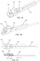
- FIG. 7A is a bottom view of the subassembly at this point
- FIG. 7C depicts plan and cross section views of the subassembly at this point.
- Suitable materials for both the second member 420 and the second wire 318 include any of the materials listed above in connection with the housing 100, and suitable diameters for the second wire 318 range from 0.1 to 0.4 mm. In some preferred embodiments (e.g., those in which the first wire 308 has a diameter of 0.13 mm), the second wire 318 has a diameter of 0.28 mm.
- any variations to the dimensions of the first wire 308 should be accompanied by a corresponding variation to the dimensions of the second wire 318 to ensure that the first shear pin 310 will always shear before the second shear pin 320.
- the second shear pin 320 maintains the connection between the second member 420 and the sliding member 200 as long as the pulling force on the second shear pin 320 in a proximal direction remains below a second threshold (while the sliding member 200 is held at a fixed position).
- the second shear pin 320 is configured to shear when the pulling force exceeds the second threshold. Shearing of the second shear pin will disconnect the second member 420 from the sliding member 200.
- the second threshold is at least double the first threshold. In some embodiments, the second threshold is between 20 and 80 N.
- Shaft 422 (shown in FIG. 5 and 6 ) is affixed to the second member 420 and is used to apply a pulling force to the second member 420 in a proximal direction. Suitable materials for the shaft 422 include any of the materials listed above in connection with the housing 100.
- the two shear pins 310, 320 described above are best seen in the cross section view of FIG. 7C . More specifically, the first shear pin 310 holds the sliding member 200 at its fixed initial position with respect to the housing 100 until the first shear pin 310 is sheared (as described below in connection with FIGS. 12-14 ); and the second shear pin 320 connects the sliding member 200 to the second member 420 until the second shear pin 320 is sheared by a force that exceeds a second threshold (as described below in connection with FIGS. 14-16 ).
- the shaft 422 can be used to hold the entire subassembly 100-422 in position with respect to the tool 400 described below in connection with FIGS. 8-10 .
- the pulling shaft 422 may be connected directly to the proximal end of the sliding member 200 (e.g., by welding).
- a weakened region is preferably designed into the distal and of the pulling shaft 422, so that when the pulling force exerted on the pulling shaft 422 exceeds a threshold, the pulling shaft 422 will break at the weakened region.
- One way to create this weakened region is to use the heat effect to modify the properties of the metal pulling shaft 422.
- a single step of welding may be used to simultaneously attach the shaft 422 to the sliding member 200 and introduce the heat effect into the distal portion of the shaft 422.
- FIG. 8-21 show how the subassembly 100-422 (depicted in FIG. 7A-C ) can be used to constrict the diameter of an annulus.
- the subassembly 100-422 is loaded into the distal end of a tool 400.
- the proximal portions 520 of the constricting cord 500 run through the patient's vasculature between the distal loop portion 510 of the constricting cord 500 and an exit point, so that those proximal portions can serve as a guide wire over which a push-tube can be guided to its destination.
- the body of the tool 400 serves as this push tube.
- the portions of the constricting cord 500 beyond the exit point are threaded (e.g., using a pre-installed guiding thread, not shown) through the openings 120, 220 of the subassembly 100-422 so that those portions of the cord follow the path depicted in FIG. 8 .
- the tool 400 is then advanced in a distal direction until the subassembly 100-422 arrives in the vicinity of the annulus, as depicted in FIG. 8 .
- the shaft of the tool 400 can include a steerable section implemented, e.g., using any of a variety of steerable catheter mechanisms that are well known to persons skilled in the relevant arts.
- the tool 400 is then advanced further in a distal direction until the subassembly 100-422 arrives at the distal loop portion 510 of the constricting cord that has been previously affixed to the annulus, as depicted in FIG. 9 .
- the distal loop portion 510 of the constricting cord is constricted by pulling the proximal ends of the constricting cord 520 while the tool 400 holds the subassembly 100-422 in place.
- This constriction is depicted in FIG. 10 , (which shows how the diameter of the distal loop portion 510 of the constricting cord is reduced when the proximal portions 520 of the constricting cord are pulled in a proximal direction through the tool 400) and FIG. 11 (which is a detail of FIG. 10 ).
- the distal loop portion 510 of the constricting cord is affixed to the annulus, the diameter of the annulus will also be reduced.
- the tool 400 to hold the subassembly 100-422 in place. This may be accomplished, for example, by applying a force in a distal direction on the body of the tool 400 so that the distal end 410 of the tool will transmit that force onto the housing 100 portion of the subassembly 100-422, so that the subassembly 100-422 will remain in place while the proximal ends of the constricting cord 520 are being pulled (as best seen in FIG. 11 ).
- FIG. 12 depicts the fastener 100/200 in its initial state, which is the same initial state depicted in FIG. 7C .
- both of the shear pins 310, 320 are intact.
- a pulling force in a proximal direction is applied to the shaft 422 e.g., using any appropriate mechanism (not shown) disposed at the proximal end of the tool 400.
- the shaft 422 transmits this pulling force to the second member 420. Because the second shear pin 320 is still intact at this point in the sequence, the pulling force that is being applied to the shaft 422 will be transmitted to the sliding member 200.
- the first shear pin 310 will hold the sliding member 200 at the initial position with respect to the housing 100. But once the pulling force exceeds the threshold for shearing the first shear pin 310, that shear pin 310 will shear, and the sliding member will begin to slide in a proximal direction with respect to the housing 100, as depicted in FIG. 13 .
- the pulling force is maintained on the shaft 422.
- the shear pin 320 continues to transmit that force onto the sliding member 200. Because the shear pin 310 has already been sheared, the sliding member 200 will continue to slide in a proximal direction with respect to the housing until the sliding member 200 reaches the position depicted in FIG. 14 with respect to the housing 100. This position of the sliding member 200 is referred to herein as the "final position.”
- the sliding member 200 cannot continue proximally beyond the final position because the distal end 240 of the sliding member 200 is too large to fit into the channel 110 in the housing. More specifically, as seen in FIG. 1A , the width of the channel 110 is defined by the first and second inner sidewalls 106. And in the illustrated embodiment, the sliding member 200 has a T-shaped distal end 240 with a width that is larger than the width of the channel 110.
- the sliding member 200 also has a pair of spring arms 230 that, prior to this point in the sequence, were compressed together by the sidewalls 106 of the housing 100, with the distal end of each of the spring arms 230 disposed within the channel 110. But once the sliding member 200 arrives at the final position depicted in FIG. 14 , the spring arms 230 will exit the proximal end of the channel 110 and automatically spring outward until the spring arms 230 reached their relaxed state. In their relaxed state, the distance between the outermost portions of the two spring arms 230 will exceed the width of the channel 110 (shown in FIG. 1A and 1B ), which prevents the sliding member 200 from sliding back in a distal direction with respect to the housing 100.
- the sliding member 200 cannot continue proximally beyond the final position (due to the distal end 240 of the sliding member 200) and cannot slide back in a distal direction (due to the operation of the spring arms 230), once the sliding member 200 reaches its final position, the sliding member 200 will be immobilized at that position.
- different approaches that will be apparent to persons skilled in the relevant arts may be used to immobilize the sliding member 200 when it reaches the final position.
- a single protrusion may be disposed at the distal end of the sliding member 200 that is shaped and positioned to block the sliding member 200 from moving proximally beyond the final position.
- a single spring arm may be used to achieve the same result.
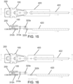
- the second shear pin 320 will prevent the second member 420 from further movement in the proximal direction. But the second member 420 is not part of the fastener that will remain behind, and must be disconnected and removed. This is accomplished by increasing the pulling force on the shaft 422 to increase the corresponding pulling force exerted by the second member 420 on the second shear pin 320. When the pulling force exceeds the second threshold, the second shear pin 320 will shear, and the second member 420 will begin to move in a proximal direction, as depicted in FIG. 15 .
- the cord 500 (which is preferably held taut during this portion of the procedure e.g., by pulling the proximal ends of the proximal portions 520 of the cord 500 in a proximal direction) retains the fastener 100/200 in the distal end of the tool 400 until the cord 500 is either cut by the cutting blade 450 (as described below in connection with FIGS. 22-23 ) or released.
- FIG. 17-18 explain how moving the sliding member 200 from its initial position to its final position (following the sequence described above in connection with FIG. 12-16 ) causes the fastener 100/200 to lock the constricting cord in place after the distal loop portion 510 of the constricting cord is constricted.
- the body of the tool 400 is omitted for clarity.
- FIG. 17A depicts the path of the constricting cord 510, 520 through the opening 220 in the sliding member 200 when the sliding member 200 is at the initial position (which corresponds to the position depicted in FIG. 12 in the sequence described above).
- FIG. 17B is similar to FIG. 17A , except that the portion of the constricting cord that passes beneath the housing 100 and sliding member 200 is shown in dashed lines.
- FIG. 17C depicts a side section detail that shows how the cord 510, 520 passes through the opening 120 in the housing 100 and through the opening 220 in the sliding member 200 when the sliding member 200 is at its initial position. At this point in the sequence, the first and second shear pins 310, 320 are still intact.
- the diameter of the distal loop portion 510 of the constricting cord can still be adjusted by progressively pulling the proximal portions of the constricting cord 520 in a proximal direction while the fastener 100/200 is held in place by the tool 400.
- FIG. 18A depicts the path of the constricting cord 510, 520 through the opening 120 in the housing 100 and the opening 220 in the sliding member 200 after the sliding member 200 has been moved to the final position (which corresponds to the position depicted in FIG. 16 in the sequence described above).
- FIG. 18B is similar to FIG. 18A , except that the path of the constricting cord that passes through both of those openings is shown in dashed lines.
- FIG. 18C is a detailed view of FIG. 18B
- FIG. 18D depicts a side section detail that shows how the cord 510, 520 passes through the opening 120 in the housing 100 and through the opening 220 in the sliding member 200 when the sliding member 200 is at its final position.
- the distal end of the opening 220 in the sliding member 200 has entered the channel (which is bounded by the upper wall 102 and the lower wall 104 of the housing 100) and has pushed a first part 522 of the cord to a position at which the first part 522 of the cord is squeezed between the upper surface 202 of the sliding member 200 and the upper wall 102 of the housing 100, and has also pushed a second part 524 of the cord to a position at which the second part 524 of the cord is squeezed between the lower surface 204 of the sliding member 200 and the lower wall 104 of the housing 100.
- the sliding member 200 and the housing are shaped and dimensioned so that the squeezing of the first and second parts 522, 524 of the cord will be sufficient to hold the cord in place when a portion of the cord that remains outside the housing is pulled by a 7 N force.
- the nominal diameter of the cord 500 is 0.15 mm; that the distal end of the opening 220 in the sliding member is 0.3 mm away, in a proximal direction, from the distal end of the channel; that the gap between the upper wall 102 of the housing 100 and the upper surface 202 of the sliding member 200 is 50 ⁇ m; and that the gap between the lower wall 104 of the housing 100 and the lower surface 204 of the sliding member 200 is also 50 ⁇ m.
- the first part 522 of the cord is squeezed between the upper surface 202 of the sliding member 200 and the upper wall 102 of the housing 100 down from its original nominal diameter of 0.15 mm to 50 ⁇ m.
- the second part 524 of the cord is squeezed between the lower surface 204 of the sliding member 200 and the lower wall 104 of the housing 100 down from its original nominal diameter of 0.15 mm to 50 ⁇ m.
- the squeezing force that is applied to those two parts 522, 524 of the cord is sufficient to prevent the cord 500 from slipping with respect to the fastener 100/200.
- the first distance between the upper wall of the housing and the lower wall of the housing will exceed the second distance between the upper surface of the sliding member and the lower surface of the sliding member by 100 ⁇ m (because a 50 ⁇ m gap appears both above and below the sliding member). But in alternative embodiments, the first distance will exceed the second distance by between 40 and 140 ⁇ m, or between 80 and 120 ⁇ m.
- the distal end of the opening 220 in the sliding member is 0.3 mm away, in a proximal direction, from the distal end of the channel. But in alternative embodiments, the distal end of the opening 220 in the sliding member is at least 0.1 mm away, in a proximal direction, from the distal end of the channel.
- the various dimensions should be scaled up or down accordingly.
- the area of the opening 220 in the sliding member 200 should be at least 10 times D 2 ; the distal end of the opening 220 in the sliding member 200 should be at least one half D away, in a proximal direction, from the distal end 112 of the channel; and the first distance should exceed the second distance by between 0.25 times D and 0.9 times D, or between 0.3 times D and one half D.
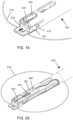
- FIG. 19 depicts the fastener 100/200 and cord 510, 520 in the same state as in FIG. 18 A-D , and also shows additional components disposed at the distal end of the tool 400 that were omitted from FIG. 18A-D for clarity. More specifically, FIG. 19 depicts the distal end 410 of the tool 400, and a cutting blade 450 (also referred to herein as a cutting element) that is used to cut the proximal portions of the cord 520 after the fastener 100/200 has fastened the cord into its reduced-diameter state.
- a cutting blade 450 also referred to herein as a cutting element
- FIG. 20 is a cutaway view of the tool 400 that reveals additional details of the interrelationship between the cutting blade 450 and the proximal portions of the cord 520.
- the cutting blade 450 has a flat body with an upper surface, a lower surface, and an opening 454 that passes between the upper surface and the lower surface.
- the proximal portions of the cord 520 pass above the distal end of the cutting blade 450, through the opening 454, and continue in a proximal direction beneath the proximal end of the cutting blade 450.
- a shaft 460 is affixed to the cutting blade 450 so that pulling the shaft 460 in a proximal direction will pull the cutting blade 450 in a proximal direction.
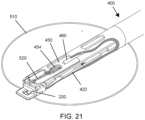
- FIG. 21 depicts the same components shown in FIG. 20 at a point in time that corresponds to FIG. 16 (i.e., after the second member 420 has pulled away in a proximal direction from the sliding member 200).
- FIGS. 22 and 23 depict the next steps in the sequence, during which the proximal portions of the cord 520 are cut.
- a cutting blade 450 is slidably positioned on a shelf 470 so that the cutting blade 450 can slide in a distal to proximal direction with respect to the shelf 470.
- the shelf 470 has an upper surface and a lower surface and a shelf opening or orifice 475 that runs between the upper surface and the lower surface of the shelf 470.
- Cutting is accomplished by first ensuring that the proximal portions of the cord 520 are taut (e.g., by pulling the proximal ends of the proximal portions 520 in a proximal direction while pushing the body 400 in a distal direction) and subsequently pulling the proximal end of the shaft 460 in a proximal direction so that the shaft 460 will pull the cutting blade 450 in a proximal direction.
- the interaction between the various components involved in cutting is described in greater detail immediately below.
- FIG. 22 depicts the position of the relevant components just prior to cutting of the proximal portions 520 of the cord.
- the opening 454 in the cutting blade coincides with or is aligned with the shelf orifice 475, and the proximal portions 520 of the cord are threaded through the various components as follows: Immediately after exiting the distal end of the housing 100, the cord makes a U-tum and passes over a saddle 480 with a smooth concave lower surface. The cord then passes above a portion of the cutting blade 450 that is distally beyond the opening 454 in the cutting blade, and then passes through the opening 454 in the cutting blade and through the orifice 475 in the shelf 470.
- the cord then passes beneath the shelf 470 proximally beyond the orifice 475, and continues in a proximal direction out through the tool 400.
- the saddle 480 and any other features in the tool 400 and fastener 100/200 that either contact or might potentially contact the cord 500 are radiused to reduce the chance of damaging the cord 500 before the cord is cut.
- the interaction of those components with the proximal portions of the cord 520 will hold the proximal portions of the cord 520 at a fixed position with respect to these components 480, 450, and 470.
- the force of the taut cord 520 holds the fastener 100/200 in place at the distal end of the tool 400 (because shear pins 310 and 320 have been sheared and no longer perform that function).
- the proximal portions 520 of the cord are threaded through the opening 220 of the sliding member 200 and flow over the saddle 408 (as best seen in FIGS. 8 and 11 ), through the opening 454 in the cutting blade 450, and through the shelf orifice 475 while the cutting blade remains in its distal position (as best seen in FIG. 22 ).
- the geometry of the saddle 480 and shelf orifice 475 is configured to suspend the cord 520 above the blade's slit shaped distal portion 456 so that the cord 500 does not snag against that slit shaped distal portion 456 of the cutting blade 450 as the cord 500 passes through the opening 454 in the cutting blade 450 during movement of the tool 400 to its distalmost position (as seen in FIGS. 8-9 ) and during constriction of the cord 500 (as seen in FIGS. 10-11 ).
- the proximal portions 520 of the cord are then cut by pulling the shaft 460 in a proximal direction, which pulls the cutting blade 450 in a proximal direction.
- This causes the slit shaped distal portion 456 (shown in FIGS. 23 and 26A ) of the opening 454 to be pulled in a proximal direction until it reaches the proximal portions of the cord 520. Because the edges of the slit shaped distal portion 456 are sharp, further movement of the cutting blade 450 in a proximal direction will cause the slit shaped distal portion 456 to cut those portions of the cord 520.
- the cutting blade 450 will move further in a proximal direction, until it reaches the position depicted in FIG. 23 .
- the cutting operation will leave behind two stubs 526 of cord.
- the upper surface of the shelf 470 lines up with the upper surface of the housing 100 so that the upper surface of the housing 100 extends the sliding platform provided by the shelf 470.
- the cutting blade 450 can slide over both the shelf 470 and a portion of the upper surface of the housing 100.
- an aligning feature e.g., the illustrated notch
- a corresponding aligning feature e.g., one or more protrusions
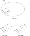
- FIGS. 26A and 26B depict upper and lower detailed views, respectively, of the cutting blade 450.
- the opening 454 in the cutting blade 450 has a proximal portion that is dimensioned to be sufficiently wide and long to allow both segments of the constricting cord 520 to slide freely through the proximal portion, and a slit shaped distal portion 456 that is sufficiently sharp and narrow to cut the constricting cord 520 when the slit shaped distal portion 456 encounters the constricting cord 520 and is pulled in a proximal direction against the constricting cord.
- the slit runs (i.e., is oriented) in a proximal-to-distal direction, and the opening 454 tapers down smoothly in a distal direction from the proximal portion towards the slit shaped distal portion 456.
- the body of the cutting blade 450 is made from 304 stainless steel. In alternative embodiments, the body of the cutting blade 450 may be made from any of the materials listed above in connection with the housing 100.
- the cutting blade 450 is 7.6 mm long (in a proximal-to-distal direction), 1.9 mm wide, and 0.13 mm thick; and the proximal portion of the opening 454 in the cutting blade 450 is 1.0 mm wide and at least 1.5 mm long.
- FIGS. 27A and 27B depict views of the cutting blade 450 at two different points in time during one example of a process for manufacturing the cutting blade 450.
- a preliminary slit 456p e.g., with a width of 20-30 ⁇ m
- FIG. 27A a preliminary slit 456p is laser cut into the body of the cutting blade 450, as depicted in FIG. 27A .
- the edges of that preliminary slit are swaged towards each other.
- One way to perform this swaging is to press a fixture with two sharp tips (e.g., fabricated from tools steel) against the surface of the cutting blade 450 on either side of the preliminary slit in a direction that is normal to the surface until the edges of the preliminary slit touch each other.
- indentations 458 are formed on the surface 452 of the cutting blade 450, and the width of the slit 456 will converge down to zero between the indentations 458 as seen in FIG. 27B , thereby forming a V-notch cutting feature with a sharp cutting edge. When this sharp cutting edge is dragged across the cord 500, it will cut the cord 500.
- a variety of alternative approaches for forming the slit shaped distal portion 456 may also be used.
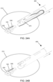
- the tool 400 can be withdrawn in a proximal direction, as depicted in FIG. 24A and 24B .
- the distal loop portion of the constricting cord 510 the fastener 100/200 (which is holding the distal loop portion of the cord 510 securely in a reduced-diameter state), and two small stubs of the constricting cord 526, as seen in FIG. 25 .
Landscapes
- Health & Medical Sciences (AREA)
- Life Sciences & Earth Sciences (AREA)
- Cardiology (AREA)
- Surgery (AREA)
- General Health & Medical Sciences (AREA)
- Public Health (AREA)
- Heart & Thoracic Surgery (AREA)
- Biomedical Technology (AREA)
- Veterinary Medicine (AREA)
- Animal Behavior & Ethology (AREA)
- Engineering & Computer Science (AREA)
- Nuclear Medicine, Radiotherapy & Molecular Imaging (AREA)
- Molecular Biology (AREA)
- Medical Informatics (AREA)
- Oral & Maxillofacial Surgery (AREA)
- Transplantation (AREA)
- Vascular Medicine (AREA)
- Rheumatology (AREA)
- Surgical Instruments (AREA)
- Prostheses (AREA)
- Measuring Pulse, Heart Rate, Blood Pressure Or Blood Flow (AREA)
Description
- This Application claims the benefit of
US Provisional Application 62/613,084 filed January 3, 2018 -
US patent 9,517,130 WO 2013/088327 andWO 2014/195786 describe a variety of approaches for affixing a constricting cord to a cardiac valve annulus or another anatomic annulus, and constricting a diameter of that cord. In particular, patent9,517,130 - Also,
US 2013/296889 A1 discloses another system and associated method for manipulating tissues and anatomical or other structures in medical applications for the purpose of treating diseases or disorders or other purposes, wherein the system includes a delivery device configured to deploy and implant anchor devices for such purposes. Further,DE 695 12 446 T2 discloses an apparatus, comprising a handle assembly, and elongated housing extending distally from the handle assembly and a tool assembly detachably connected to a distal end of the body portion and remotely operable from the handle, wherein the tool assembly enables a surgeon to compress and maintain a securing member upon suture material in a body cavity and also provides means to cut unsecured suture material which extends from the compressed securing member. - Further devices and techniques for affixing a constricting cord to a cardiac valve annulus or another anatomic annulus and for constricting a diameter of that cord are known from
EP 0 634 142 A2 ,US 2010/240951 A1 , andUS 2007/276437 A1 . - In view of the above background, the present invention is defined by an apparatus for reducing a diameter of a cord according to claim 1. Further advantageous embodiments are described in the dependent claims.
- An aspect of the invention is thus directed to an apparatus for reducing a diameter of a cord that has been previously affixed to an annulus. The apparatus comprises a housing having a distal portion and a distal end. The apparatus also comprises a shelf positioned in the distal portion of the housing that extends in a distal-to-proximal direction, the shelf having an upper surface, a lower surface, and a shelf opening that runs between the upper and lower surfaces of the shelf. The apparatus also comprises a cutting element positioned above the shelf and arranged so that the cutting element can slide in the distal-to-proximal direction with respect to the shelf, the cutting element having a flat body with an upper surface, a lower surface, and an opening that passes between the upper and lower surfaces of the cutting element, the opening of the cutting element having (a) a proximal portion that is dimensioned so that two segments of the cord can slide freely through the proximal portion and (b) a slit shaped distal portion with sharp edges, wherein the slit shaped distal portion is oriented in the distal-to-proximal direction. The apparatus also comprises a fastener positioned at the distal end of the housing, the fastener having an opening. The fastener is movable from a first state in which the cord is free to slide through the opening in the fastener to a second state in which the cord is locked in place.
- In some embodiments of the apparatus, the fastener, the shelf, and the cutting element are configured such that the cord can be threaded through the opening in the fastener when the fastener is in the first state so that that after the fastener is moved to the second state, the cord will be arranged in a pre-cutting position in which the cord passes above a portion of the cutting element that is distally beyond the opening of the cutting element, and then passes through the opening of the cutting element and through the opening in the shelf. In these embodiments, the cutting element is configured such that when the cord is arranged in the pre-cutting position, movement of the cutting element in the proximal direction will cause the slit shaped distal portion of the opening of the cutting element to move in a proximal direction until the slit shaped distal portion reaches the cord and cuts the cord.
- Some embodiments of the apparatus further comprise a shaft that runs in the distal-to-proximal direction. The shaft is affixed to the cutting element so that pulling the shaft in a proximal direction will pull the cutting element in a proximal direction.
- In some embodiments of the apparatus, the upper surface of the shelf lines up with the upper surface of the fastener so that the upper surface of the fastener extends a sliding platform provided by the shelf. In some of these embodiments, the cutting element is configured to slide over both the shelf and a portion of the upper surface of the fastener. In some of these embodiments, the distal end of the shelf has a first aligning feature (e.g., a notch), and the proximal end of the fastener has a second aligning feature (e.g., a protrusion) that matches the first aligning feature.
- In some embodiments of the apparatus, the opening of the cutting element tapers down smoothly in a distal direction from the proximal portion of the opening of the cutting element towards the slit shaped distal portion of the opening of the cutting element.
- In some embodiments of the apparatus, the slit shaped distal portion is formed by laser cutting the flat body of the cutting element to form a first slit having a width of 20-30 µm, and subsequently swaging the edges of the first slit towards each other to reduce the width of the first slit.
-
-
FIG. 1A depicts a fastener for fastening portions of a constricting cord together. The fastener includes a housing and a sliding member. -
FIG. 1B depicts a side view of the housing as viewed from a point that is distally beyond the distal end of the housing. -
FIG. 2 depicts the sliding member and the housing at a particular alignment point. -
FIG. 3A and 3B , depict top and bottom views, respectively, of the fastener at the same alignment point with a wire threaded through a pair of holes. -
FIG. 4A and 4B , depict top and bottom views, respectively, of the fastener after the wire has been welded to the housing and to the sliding member. -
FIG. 5 depicts a second member with a second wire welded thereto. -
FIG. 6 depicts the second wire threaded through a hole in the sliding member. -
FIG. 7A and 7B depicts upper and lower views, respectively, of the fastener after it has been connected to the second member. -
FIG. 7C depicts plan and section views of the fastener after it has been connected to the second member. -
FIG. 8 depicts a subassembly that includes the fastener loaded into the distal end of a tool and threaded onto a constricting cord. -
FIG. 9 depicts the same tool after it has been advanced until the subassembly arrives at the distal loop portion of the constricting cord. -
FIG. 10 depicts the same tool after it has been used to reduce the diameter of the distal loop portion of the constricting cord. -
FIG. 11 is a detail ofFIG. 10 . -
FIG. 12 depicts the fastener in its initial state. -
FIG. 13 depicts the fastener after shearing of the first shear pin and after the sliding member has begun to slide in a proximal direction with respect to the housing. -
FIG. 14 depicts the same fastener after further sliding in the proximal direction. -
FIG. 15 depicts the same fastener after shearing of the second shear pin and after the sliding member has begun to slide further in a proximal direction with respect to the housing. -
FIG. 16 depicts the same fastener after further sliding in the proximal direction. -
FIG. 17A depicts the path of the constricting cord through the opening in the sliding member when the sliding member is at the initial position. -
FIG. 17B is similar toFIG. 17A but shows additional features of the path of the constricting cord. -
FIG. 17C depicts a side section detail ofFIG. 17A . -
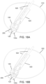
FIG. 18A depicts the path of the constricting cord through the openings in the housing and the sliding member after the sliding member has been moved to the final position. -
FIG. 18B is similar toFIG. 18A , but shows additional features of the path of the constricting cord. -
FIG. 18C is a detailed view ofFIG. 18B . -
FIG. 18D depicts a side section detail ofFIG. 18A . -
FIG. 19 depicts the fastener and cord in the same state as inFIG. 18A-D , plus also shows additional components disposed at the distal end of the tool. -
FIG. 20 is a cutaway view of the tool that reveals additional details of the interrelationship between the cutting blade and the proximal portions of the cord. -
FIG. 21 depicts the same components shown inFIG. 20 after the second member has pulled away in a proximal direction from the sliding member. -
FIG. 22 depicts the next step in the sequence, just before the proximal portions of the cord are cut. -
FIG. 23 depicts the next step in the sequence, after the blade has moved in a proximal direction and cut the proximal portions of the cord. -
FIG. 24A and 24B depict withdrawal of the tool in a proximal direction. -
FIG 25 depicts the components that are left behind in a patient's body after withdrawal of the tool. -
FIG. 26A and FIG. 26B depict upper and lower views, respectively of the cutting blade. -
FIG. 27A and FIG. 27B depict detailed views of the lower face of the cutting blade before and after swaging of that component, respectively. - Various embodiments are described in detail below with reference to the accompanying drawings, wherein like reference numerals represent like elements.
- As explained in
US patent 9,517,130 - Two proximal portions (or segments) of the constricting cord run from outside the patient's body to the implanted distal loop portion of the constricting cord. As explained in
US patent 9,517,130 - The remainder of this application describes a variety of approaches for fastening the distal ends of the proximal portions of the constricting cord together.
-
FIG. 1A depicts the two primary components of afastener 100/200 that may be used to fasten the distal ends of the proximal portions of the constricting cord together. More specifically, the two primary components of the fastener are thehousing 100 and the slidingmember 200.FIG. 1B depicts a side view of thehousing 100 as viewed from a point that is distally beyond the distal end of thehousing 100. The housing has anupper wall 102 and alower wall 104 with achannel 110 disposed between theupper wall 102 and thelower wall 104. Thechannel 110 has adistal end 112. In the illustrated embodiment, theupper wall 102 and thelower wall 104 are both flat and are parallel to each other; and the housing also has sidewalls 106 that run between theupper wall 102 and thelower wall 104 to form a rigid structure. In the illustrated embodiment, thesidewalls 106 are also flat and parallel to each other. And in the illustrated embodiment, an extension portion 104X of thelower wall 104 extends distally beyond the distal end of thechannel 112. This extension portion 104X has anopening 120. In some preferred embodiments, the area of thisopening 120 is at least 0.4 mm2. In alternative embodiments, the area of thisopening 120 is between 0.3 and 1.0 mm2. Suitable materials for forming thehousing 100 include cobalt chromium alloys (including but not limited to MP35N, L605, Elgiloy, etc.), surgical stainless steel (including but not limited to 305 ss, 316 ss, etc.), and other biocompatible metals. In some preferred embodiments, thehousing 100 is dimensioned so that thechannel 110 is 1.5 mm long (in a proximal-to-distal direction) 1.8 mm wide, and 0.64 mm tall; and so that the extension portion 104X extends 1.5 mm distally beyond the distal end of thechannel 112. - The sliding
member 200 has anupper surface 202 and a lower surface 204 (shown inFIG. 3B ) and the slidingmember 200 has anopening 220 that runs between theupper surface 202 and thelower surface 204. In some preferred embodiments, the area of thisopening 220 is at least 0.4 mm2. In alternative embodiments, the area of thisopening 220 is between 0.3 and 1.0 mm2. Theopening 220 has a distal end. Preferably, the edges of thechannel 110 of the housing and theopening 220 of the sliding member are not sharp, to reduce the chance of damaging the cord. Suitable materials for forming the slidingmember 200 include any of the materials listed above in connection with thehousing 100. In some preferred embodiments, the slidingmember 200 is 4.6 mm long (in a proximal-to-distal direction), 0.53 mm high, and 1.8 mm wide; and the distal end of the sliding member 200 (which prevents the slidingmember 200 from entering thechannel 110 in the housing) is 2.3 mm wide. Of course, if any of the dimensions of thehousing 100 deviates from the dimensions specified above, corresponding modifications to the dimensions of the slidingmember 200 should be made to maintain the interactions between those two components described herein. -
FIGS. 2-7 depict one preferred approach for assembling a subassembly that retains the slidingmember 200 at an initial position with respect to thehousing 100 prior to deployment of the fastener. - As seen in
FIG. 1A , thelower wall 104 of thehousing 100 has a throughhole 108, and the sliding member has a throughhole 208. In some preferred embodiments, the diameter of these through holes is between 0.1 mm and 0.4 mm, and in some preferred embodiments, the diameter of these through holes is about 0.15 mm. The slidingmember 200 and thehousing 100 are configured with respect to each other so that before the subassembly is assembled, the slidingmember 200 is free to slide in a proximal direction with respect to thehousing 100 until the throughhole 108 of the housing lines up with the throughhole 208 of the sliding member as depicted inFIG. 2 . At this point, awire 308 is threaded through the throughholes FIG. 3A and 3B , which are top and bottom views, respectively. Suitable materials for thiswire 308 include any of the materials listed above in connection with thehousing 100, and suitable diameters for thiswire 308 range from 0.075 to 0.4 mm. In some preferred embodiments, thewire 308 has a diameter of 0.13 mm. - Note that when the
housing 100 and the slidingmember 200 are lined up at this position, theopening 120 of the housing will line up with theopening 220 of the sliding member, as seen inFIGS. 3A and 3B . - The upper end of the
wire 308 is then welded to theupper surface 202 of the slidingmember 200 at weld point 309 (as seen inFIG. 4A ); and the lower end of thewire 308 is welded to the bottom of thehousing 100 at weld point 309 (as seen inFIG. 4B ). Welding the upper and lower ends of thewire 308 to theupper surface 202 of the slidingmember 200 and the bottom of thehousing 100, respectively, forms a first shear pin 310 (shown inFIG. 7C ) that holds the slidingmember 200 at a fixed position with respect to the housing 100 (referred to herein as the "initial position" ) until thefirst shear pin 310 is sheared by a force that exceeds a first threshold. In some embodiments, the first threshold is between 5 and 10 N. Note that while welding is the preferred approach for forming thefirst shear pin 310, alternative approaches that will be apparent to persons skilled in the relevant arts may also be used to form theshear pin 310 that holds the slidingmember 200 at a fixed position with respect to thehousing 100. - A
second member 420 is then positioned adjacent to the proximal end of the slidingmember 200 and a second shear pin 320 (shown inFIG. 7C ) is affixed between thesecond member 420 and the slidingmember 200. One approach for forming thissecond shear pin 320 is depicted inFIGS. 5-7 . InFIG. 5 , the lower end of asecond wire 318 is welded to thesecond member 420 atweld point 319. Subsequently, the upper end of thesecond wire 318 is threaded through the hole 218 (shown inFIG. 1 ) in the slidingmember 200, as depicted inFIG. 6 . The upper end of the second wire is then welded on to the slidingmember 200 atweld point 319, as depicted inFIG. 7A. FIG. 7B is a bottom view of the subassembly at this point, andFIG. 7C depicts plan and cross section views of the subassembly at this point. Suitable materials for both thesecond member 420 and thesecond wire 318 include any of the materials listed above in connection with thehousing 100, and suitable diameters for thesecond wire 318 range from 0.1 to 0.4 mm. In some preferred embodiments (e.g., those in which thefirst wire 308 has a diameter of 0.13 mm), thesecond wire 318 has a diameter of 0.28 mm. As will be appreciated by persons skilled in the relevant arts, any variations to the dimensions of thefirst wire 308 should be accompanied by a corresponding variation to the dimensions of thesecond wire 318 to ensure that thefirst shear pin 310 will always shear before thesecond shear pin 320. - The
second shear pin 320 maintains the connection between thesecond member 420 and the slidingmember 200 as long as the pulling force on thesecond shear pin 320 in a proximal direction remains below a second threshold (while the slidingmember 200 is held at a fixed position). In addition, thesecond shear pin 320 is configured to shear when the pulling force exceeds the second threshold. Shearing of the second shear pin will disconnect thesecond member 420 from the slidingmember 200. In some preferred embodiments, the second threshold is at least double the first threshold. In some embodiments, the second threshold is between 20 and 80 N. Shaft 422 (shown inFIG. 5 and 6 ) is affixed to thesecond member 420 and is used to apply a pulling force to thesecond member 420 in a proximal direction. Suitable materials for theshaft 422 include any of the materials listed above in connection with thehousing 100. - The two
shear pins FIG. 7C . More specifically, thefirst shear pin 310 holds the slidingmember 200 at its fixed initial position with respect to thehousing 100 until thefirst shear pin 310 is sheared (as described below in connection withFIGS. 12-14 ); and thesecond shear pin 320 connects the slidingmember 200 to thesecond member 420 until thesecond shear pin 320 is sheared by a force that exceeds a second threshold (as described below in connection withFIGS. 14-16 ). Note that while welding is the preferred approach for forming thesecond shear pin 320, alternative approaches that will be apparent to persons skilled in the relevant arts may also be used to form theshear pin 320 that holds the slidingmember 200 at a fixed position with respect to thesecond member 420. Notably, when the configuration depicted inFIGS. 7A-C is used, theshaft 422 can be used to hold the entire subassembly 100-422 in position with respect to thetool 400 described below in connection withFIGS. 8-10 . - In some alternative embodiments (not shown) instead of affixing the
shaft 422 to thesecond member 420 and connecting thesecond member 420 to the slidingmember 200 using a shear pin 320 (as described above in connection withFIG. 7A-C ), the pullingshaft 422 may be connected directly to the proximal end of the sliding member 200 (e.g., by welding). In these embodiments, a weakened region is preferably designed into the distal and of the pullingshaft 422, so that when the pulling force exerted on the pullingshaft 422 exceeds a threshold, the pullingshaft 422 will break at the weakened region. One way to create this weakened region is to use the heat effect to modify the properties of themetal pulling shaft 422. Optionally, a single step of welding may be used to simultaneously attach theshaft 422 to the slidingmember 200 and introduce the heat effect into the distal portion of theshaft 422. -
FIG. 8-21 show how the subassembly 100-422 (depicted inFIG. 7A-C ) can be used to constrict the diameter of an annulus. Turning first toFIG. 8 , the subassembly 100-422 is loaded into the distal end of atool 400. As explained above, theproximal portions 520 of the constrictingcord 500 run through the patient's vasculature between thedistal loop portion 510 of the constrictingcord 500 and an exit point, so that those proximal portions can serve as a guide wire over which a push-tube can be guided to its destination. The body of thetool 400 serves as this push tube. The portions of the constrictingcord 500 beyond the exit point are threaded (e.g., using a pre-installed guiding thread, not shown) through theopenings FIG. 8 . Thetool 400 is then advanced in a distal direction until the subassembly 100-422 arrives in the vicinity of the annulus, as depicted inFIG. 8 . Optionally, the shaft of thetool 400 can include a steerable section implemented, e.g., using any of a variety of steerable catheter mechanisms that are well known to persons skilled in the relevant arts. - The
tool 400 is then advanced further in a distal direction until the subassembly 100-422 arrives at thedistal loop portion 510 of the constricting cord that has been previously affixed to the annulus, as depicted inFIG. 9 . - After the subassembly 100-422 reaches this position, the
distal loop portion 510 of the constricting cord is constricted by pulling the proximal ends of the constrictingcord 520 while thetool 400 holds the subassembly 100-422 in place. This constriction is depicted inFIG. 10 , (which shows how the diameter of thedistal loop portion 510 of the constricting cord is reduced when theproximal portions 520 of the constricting cord are pulled in a proximal direction through the tool 400) andFIG. 11 (which is a detail ofFIG. 10 ). And because thedistal loop portion 510 of the constricting cord is affixed to the annulus, the diameter of the annulus will also be reduced. - During constriction of the
cord 500, there will be significant tension on the cord. This tension will pull the regions of thedistal loop portion 510 of the cord on either side of theopening 120 in thehousing 100 and theopening 220 in the slidingmember 200 apart from each other (limited by the confines of theopenings 120 and 220). As a result, if theproximal portions 520 happen to be twisted adjacent to the interface with thedistal loop portion 510 when the subassembly 100-422 reaches the annulus, the tension will cause the twists to move in a proximal direction along theproximal portions 520 of the cord until the twists move proximally beyond the region that will ultimately be clipped together (as described below in connection withFIGS. 17-18 ). This is advantageous because it improves the repeatability and reliability of the clip fastening procedure. - Note that while the proximal ends of the constricting
cord 520 are being pulled in a proximal direction, it is important for thetool 400 to hold the subassembly 100-422 in place. This may be accomplished, for example, by applying a force in a distal direction on the body of thetool 400 so that thedistal end 410 of the tool will transmit that force onto thehousing 100 portion of the subassembly 100-422, so that the subassembly 100-422 will remain in place while the proximal ends of the constrictingcord 520 are being pulled (as best seen inFIG. 11 ). - After the diameter of the annulus has been constricted as described above, tension is maintained on the proximal ends of the constricting
cord 520, and a force in a distal direction is applied to thehousing 100 by thetool 400 until deployment of thefastener 100/200 (described below in connection withFIGS. 12-21 ) is complete. -
FIG. 12 depicts thefastener 100/200 in its initial state, which is the same initial state depicted inFIG. 7C . In this initial state, both of the shear pins 310, 320 are intact. While thehousing 100 is held in place by thetool 400, a pulling force in a proximal direction is applied to theshaft 422 e.g., using any appropriate mechanism (not shown) disposed at the proximal end of thetool 400. Theshaft 422 transmits this pulling force to thesecond member 420. Because thesecond shear pin 320 is still intact at this point in the sequence, the pulling force that is being applied to theshaft 422 will be transmitted to the slidingmember 200. - As long as the pulling force that is being applied to the
shaft 422 remains below the threshold force for shearing thefirst shear pin 310, thefirst shear pin 310 will hold the slidingmember 200 at the initial position with respect to thehousing 100. But once the pulling force exceeds the threshold for shearing thefirst shear pin 310, thatshear pin 310 will shear, and the sliding member will begin to slide in a proximal direction with respect to thehousing 100, as depicted inFIG. 13 . - The pulling force is maintained on the
shaft 422. Theshear pin 320 continues to transmit that force onto the slidingmember 200. Because theshear pin 310 has already been sheared, the slidingmember 200 will continue to slide in a proximal direction with respect to the housing until the slidingmember 200 reaches the position depicted inFIG. 14 with respect to thehousing 100. This position of the slidingmember 200 is referred to herein as the "final position." The slidingmember 200 cannot continue proximally beyond the final position because thedistal end 240 of the slidingmember 200 is too large to fit into thechannel 110 in the housing. More specifically, as seen inFIG. 1A , the width of thechannel 110 is defined by the first and secondinner sidewalls 106. And in the illustrated embodiment, the slidingmember 200 has a T-shapeddistal end 240 with a width that is larger than the width of thechannel 110. - In the illustrated embodiment, the sliding
member 200 also has a pair ofspring arms 230 that, prior to this point in the sequence, were compressed together by thesidewalls 106 of thehousing 100, with the distal end of each of thespring arms 230 disposed within thechannel 110. But once the slidingmember 200 arrives at the final position depicted inFIG. 14 , thespring arms 230 will exit the proximal end of thechannel 110 and automatically spring outward until thespring arms 230 reached their relaxed state. In their relaxed state, the distance between the outermost portions of the twospring arms 230 will exceed the width of the channel 110 (shown inFIG. 1A and 1B ), which prevents the slidingmember 200 from sliding back in a distal direction with respect to thehousing 100. - Because the sliding
member 200 cannot continue proximally beyond the final position (due to thedistal end 240 of the sliding member 200) and cannot slide back in a distal direction (due to the operation of the spring arms 230), once the slidingmember 200 reaches its final position, the slidingmember 200 will be immobilized at that position. In alternative embodiments, different approaches that will be apparent to persons skilled in the relevant arts may be used to immobilize the slidingmember 200 when it reaches the final position. For example, instead of having a T-shaped distal end, a single protrusion may be disposed at the distal end of the slidingmember 200 that is shaped and positioned to block the slidingmember 200 from moving proximally beyond the final position. Similarly, instead of relying on a pair ofspring arms 230 to prevent the slidingmember 200 from moving backwards in a distal direction from the final position, a single spring arm may be used to achieve the same result. - As long as the pulling force on the
shaft 422 remains below the second threshold (i.e. the threshold required to shear the second shear pin 320), thesecond shear pin 320 will prevent thesecond member 420 from further movement in the proximal direction. But thesecond member 420 is not part of the fastener that will remain behind, and must be disconnected and removed. This is accomplished by increasing the pulling force on theshaft 422 to increase the corresponding pulling force exerted by thesecond member 420 on thesecond shear pin 320. When the pulling force exceeds the second threshold, thesecond shear pin 320 will shear, and thesecond member 420 will begin to move in a proximal direction, as depicted inFIG. 15 . Continued application of pulling force on theshaft 422 will move thesecond member 420 further away from the sliding member 200 (which is now locked to thehousing 100 at the final position), as seen inFIG. 16 . Advantageously, the design described above using twoshear pins first shear pin 310 will always shear before thesecond shear pin 320. - Note that after the
second shear pin 320 has sheared and thesecond member 420 has pulled away from the slidingmember 200, the cord 500 (which is preferably held taut during this portion of the procedure e.g., by pulling the proximal ends of theproximal portions 520 of thecord 500 in a proximal direction) retains thefastener 100/200 in the distal end of thetool 400 until thecord 500 is either cut by the cutting blade 450 (as described below in connection withFIGS. 22-23 ) or released. - Having explained the interaction between the sliding
member 200 and thehousing 100 in connection withFIG. 12-16 , we return to the explanation of how the slidingmember 200 and thehousing 100 interact with the constrictingcord 500 to fasten that cord in its constricted state. - The last time the constricting
cord 500 was mentioned in this application was in connection withFIGS. 10-11 , at which point theproximal portions 520 of the constricting cord were threaded through theopenings distal loop portion 510 of the constricting cord was subsequently constricted by pulling the proximal ends of the constrictingcord 520 while thetool 400 held the subassembly 100-422 in place. -
FIG. 17-18 explain how moving the slidingmember 200 from its initial position to its final position (following the sequence described above in connection withFIG. 12-16 ) causes thefastener 100/200 to lock the constricting cord in place after thedistal loop portion 510 of the constricting cord is constricted. In this sequence of figures, the body of thetool 400 is omitted for clarity. -
FIG. 17A depicts the path of the constrictingcord opening 220 in the slidingmember 200 when the slidingmember 200 is at the initial position (which corresponds to the position depicted inFIG. 12 in the sequence described above).FIG. 17B is similar toFIG. 17A , except that the portion of the constricting cord that passes beneath thehousing 100 and slidingmember 200 is shown in dashed lines.FIG. 17C depicts a side section detail that shows how thecord opening 120 in thehousing 100 and through theopening 220 in the slidingmember 200 when the slidingmember 200 is at its initial position. At this point in the sequence, the first and second shear pins 310, 320 are still intact. In addition, the diameter of thedistal loop portion 510 of the constricting cord can still be adjusted by progressively pulling the proximal portions of the constrictingcord 520 in a proximal direction while thefastener 100/200 is held in place by thetool 400. -
FIG. 18A depicts the path of the constrictingcord opening 120 in thehousing 100 and theopening 220 in the slidingmember 200 after the slidingmember 200 has been moved to the final position (which corresponds to the position depicted inFIG. 16 in the sequence described above).FIG. 18B is similar toFIG. 18A , except that the path of the constricting cord that passes through both of those openings is shown in dashed lines.FIG. 18C is a detailed view ofFIG. 18B , andFIG. 18D depicts a side section detail that shows how thecord opening 120 in thehousing 100 and through theopening 220 in the slidingmember 200 when the slidingmember 200 is at its final position. - At this point in the sequence (as best seen in
FIG. 18C and 18D ), the distal end of theopening 220 in the slidingmember 200 has entered the channel (which is bounded by theupper wall 102 and thelower wall 104 of the housing 100) and has pushed afirst part 522 of the cord to a position at which thefirst part 522 of the cord is squeezed between theupper surface 202 of the slidingmember 200 and theupper wall 102 of thehousing 100, and has also pushed asecond part 524 of the cord to a position at which thesecond part 524 of the cord is squeezed between thelower surface 204 of the slidingmember 200 and thelower wall 104 of thehousing 100. In some preferred embodiments, the slidingmember 200 and the housing are shaped and dimensioned so that the squeezing of the first andsecond parts - Assume, for example, that the nominal diameter of the
cord 500 is 0.15 mm; that the distal end of theopening 220 in the sliding member is 0.3 mm away, in a proximal direction, from the distal end of the channel; that the gap between theupper wall 102 of thehousing 100 and theupper surface 202 of the slidingmember 200 is 50 µm; and that the gap between thelower wall 104 of thehousing 100 and thelower surface 204 of the slidingmember 200 is also 50 µm. When these dimensions are used, thefirst part 522 of the cord is squeezed between theupper surface 202 of the slidingmember 200 and theupper wall 102 of thehousing 100 down from its original nominal diameter of 0.15 mm to 50 µm. Similarly, thesecond part 524 of the cord is squeezed between thelower surface 204 of the slidingmember 200 and thelower wall 104 of thehousing 100 down from its original nominal diameter of 0.15 mm to 50 µm. In this situation, the squeezing force that is applied to those twoparts cord 500 from slipping with respect to thefastener 100/200. - Note that in this example, the first distance between the upper wall of the housing and the lower wall of the housing will exceed the second distance between the upper surface of the sliding member and the lower surface of the sliding member by 100 µm (because a 50 µm gap appears both above and below the sliding member). But in alternative embodiments, the first distance will exceed the second distance by between 40 and 140 µm, or between 80 and 120 µm. Note also that in this example, the distal end of the
opening 220 in the sliding member is 0.3 mm away, in a proximal direction, from the distal end of the channel. But in alternative embodiments, the distal end of theopening 220 in the sliding member is at least 0.1 mm away, in a proximal direction, from the distal end of the channel. - When the nominal diameter of the cord is larger or smaller than 0.15 mm, the various dimensions should be scaled up or down accordingly. For example, if the cord has a nominal diameter of D, the area of the
opening 220 in the slidingmember 200 should be at least 10 times D2; the distal end of theopening 220 in the slidingmember 200 should be at least one half D away, in a proximal direction, from thedistal end 112 of the channel; and the first distance should exceed the second distance by between 0.25 times D and 0.9 times D, or between 0.3 times D and one half D. -
FIG. 19 depicts thefastener 100/200 andcord FIG. 18 A-D , and also shows additional components disposed at the distal end of thetool 400 that were omitted fromFIG. 18A-D for clarity. More specifically,FIG. 19 depicts thedistal end 410 of thetool 400, and a cutting blade 450 (also referred to herein as a cutting element) that is used to cut the proximal portions of thecord 520 after thefastener 100/200 has fastened the cord into its reduced-diameter state. -
FIG. 20 is a cutaway view of thetool 400 that reveals additional details of the interrelationship between thecutting blade 450 and the proximal portions of thecord 520. More specifically, thecutting blade 450 has a flat body with an upper surface, a lower surface, and anopening 454 that passes between the upper surface and the lower surface. The proximal portions of thecord 520 pass above the distal end of thecutting blade 450, through theopening 454, and continue in a proximal direction beneath the proximal end of thecutting blade 450. Ashaft 460 is affixed to thecutting blade 450 so that pulling theshaft 460 in a proximal direction will pull thecutting blade 450 in a proximal direction. -
FIG. 21 depicts the same components shown inFIG. 20 at a point in time that corresponds toFIG. 16 (i.e., after thesecond member 420 has pulled away in a proximal direction from the sliding member 200). -
FIGS. 22 and 23 depict the next steps in the sequence, during which the proximal portions of thecord 520 are cut. Acutting blade 450 is slidably positioned on ashelf 470 so that thecutting blade 450 can slide in a distal to proximal direction with respect to theshelf 470. Theshelf 470 has an upper surface and a lower surface and a shelf opening ororifice 475 that runs between the upper surface and the lower surface of theshelf 470. Cutting is accomplished by first ensuring that the proximal portions of thecord 520 are taut (e.g., by pulling the proximal ends of theproximal portions 520 in a proximal direction while pushing thebody 400 in a distal direction) and subsequently pulling the proximal end of theshaft 460 in a proximal direction so that theshaft 460 will pull thecutting blade 450 in a proximal direction. The interaction between the various components involved in cutting is described in greater detail immediately below. -
FIG. 22 depicts the position of the relevant components just prior to cutting of theproximal portions 520 of the cord. At this point in time, theopening 454 in the cutting blade coincides with or is aligned with theshelf orifice 475, and theproximal portions 520 of the cord are threaded through the various components as follows: Immediately after exiting the distal end of thehousing 100, the cord makes a U-tum and passes over asaddle 480 with a smooth concave lower surface. The cord then passes above a portion of thecutting blade 450 that is distally beyond theopening 454 in the cutting blade, and then passes through theopening 454 in the cutting blade and through theorifice 475 in theshelf 470. The cord then passes beneath theshelf 470 proximally beyond theorifice 475, and continues in a proximal direction out through thetool 400. In some preferred embodiments, thesaddle 480 and any other features in thetool 400 andfastener 100/200 that either contact or might potentially contact thecord 500 are radiused to reduce the chance of damaging thecord 500 before the cord is cut. When the proximal portions of thecord 520 are pulled taut, the interaction of those components with the proximal portions of thecord 520 will hold the proximal portions of thecord 520 at a fixed position with respect to thesecomponents taut cord 520 holds thefastener 100/200 in place at the distal end of the tool 400 (because shear pins 310 and 320 have been sheared and no longer perform that function). - Note that before the cord is clipped by the
fastener 100/200 (as described above in connection withFIGS. 17-18 ), theproximal portions 520 of the cord are threaded through theopening 220 of the slidingmember 200 and flow over the saddle 408 (as best seen inFIGS. 8 and11 ), through theopening 454 in thecutting blade 450, and through theshelf orifice 475 while the cutting blade remains in its distal position (as best seen inFIG. 22 ). The geometry of thesaddle 480 andshelf orifice 475 is configured to suspend thecord 520 above the blade's slit shapeddistal portion 456 so that thecord 500 does not snag against that slit shapeddistal portion 456 of thecutting blade 450 as thecord 500 passes through theopening 454 in thecutting blade 450 during movement of thetool 400 to its distalmost position (as seen inFIGS. 8-9 ) and during constriction of the cord 500 (as seen inFIGS. 10-11 ). - Returning to
FIG. 22 , theproximal portions 520 of the cord are then cut by pulling theshaft 460 in a proximal direction, which pulls thecutting blade 450 in a proximal direction. This causes the slit shaped distal portion 456 (shown inFIGS. 23 and26A ) of theopening 454 to be pulled in a proximal direction until it reaches the proximal portions of thecord 520. Because the edges of the slit shapeddistal portion 456 are sharp, further movement of thecutting blade 450 in a proximal direction will cause the slit shapeddistal portion 456 to cut those portions of thecord 520. Continued pulling on theshaft 460 will cause thecutting blade 450 to move further in a proximal direction, until it reaches the position depicted inFIG. 23 . The cutting operation will leave behind twostubs 526 of cord. In some preferred embodiments and as best seen inFIG. 23 , the upper surface of theshelf 470 lines up with the upper surface of thehousing 100 so that the upper surface of thehousing 100 extends the sliding platform provided by theshelf 470. In these embodiments, thecutting blade 450 can slide over both theshelf 470 and a portion of the upper surface of thehousing 100. Optionally, an aligning feature (e.g., the illustrated notch) may be included at the distal end of theshelf 470, and a corresponding aligning feature (e.g., one or more protrusions) may be provided at the proximal end of thehousing 100 to improve the alignment between theshelf 470 and thehousing 100. -
FIGS. 26A and 26B depict upper and lower detailed views, respectively, of thecutting blade 450. In the illustrated embodiment, theopening 454 in thecutting blade 450 has a proximal portion that is dimensioned to be sufficiently wide and long to allow both segments of the constrictingcord 520 to slide freely through the proximal portion, and a slit shapeddistal portion 456 that is sufficiently sharp and narrow to cut the constrictingcord 520 when the slit shapeddistal portion 456 encounters the constrictingcord 520 and is pulled in a proximal direction against the constricting cord. The slit runs (i.e., is oriented) in a proximal-to-distal direction, and theopening 454 tapers down smoothly in a distal direction from the proximal portion towards the slit shapeddistal portion 456. In some embodiments, the body of thecutting blade 450 is made from 304 stainless steel. In alternative embodiments, the body of thecutting blade 450 may be made from any of the materials listed above in connection with thehousing 100. In some preferred embodiments, thecutting blade 450 is 7.6 mm long (in a proximal-to-distal direction), 1.9 mm wide, and 0.13 mm thick; and the proximal portion of theopening 454 in thecutting blade 450 is 1.0 mm wide and at least 1.5 mm long. -
FIGS. 27A and 27B depict views of thecutting blade 450 at two different points in time during one example of a process for manufacturing thecutting blade 450. In this example, apreliminary slit 456p (e.g., with a width of 20-30 µm) is laser cut into the body of thecutting blade 450, as depicted inFIG. 27A . Subsequently, the edges of that preliminary slit are swaged towards each other. One way to perform this swaging is to press a fixture with two sharp tips (e.g., fabricated from tools steel) against the surface of thecutting blade 450 on either side of the preliminary slit in a direction that is normal to the surface until the edges of the preliminary slit touch each other. When this approach is used,indentations 458 are formed on thesurface 452 of thecutting blade 450, and the width of theslit 456 will converge down to zero between theindentations 458 as seen inFIG. 27B , thereby forming a V-notch cutting feature with a sharp cutting edge. When this sharp cutting edge is dragged across thecord 500, it will cut thecord 500. A variety of alternative approaches for forming the slit shapeddistal portion 456 may also be used. - After the
cord 500 has been cut (as described above in connection withFIG. 23 ), thetool 400 can be withdrawn in a proximal direction, as depicted inFIG. 24A and 24B . After thetool 400 has been completely withdrawn, all that will remain in the patient's body is the distal loop portion of the constrictingcord 510, thefastener 100/200 (which is holding the distal loop portion of thecord 510 securely in a reduced-diameter state), and two small stubs of the constrictingcord 526, as seen inFIG. 25 . Note that because thefastener 100/200 is holding the distal loop portion of thecord 510 in a reduced-diameter state and that cord was previously affixed to the annulus, the annulus will also be held securely in a reduced-diameter state. - While the present invention has been disclosed with reference to certain embodiments, numerous modifications, alterations, and changes to the described embodiments are possible without departing from the invention, as defined in the appended claims. Accordingly, it is intended that the present invention not be limited to the described embodiments, but that it has the full scope defined by the language of the following claims .
Claims (9)
- An apparatus for reducing a diameter of a cord (510, 520) that has been previously affixed to an annulus, the apparatus comprising:a housing having a distal portion and a distal end (410);a shelf (470) positioned in the distal portion of the housing that extends in a distal-to-proximal direction, the shelf (470) having an upper surface, a lower surface, and a shelf opening (475) that runs between the upper and lower surfaces of the shelf (470);a cutting element (450) positioned above the shelf (470) and arranged so that the cutting element (450) can slide in the distal-to-proximal direction with respect to the shelf (470), the cutting element (450) having a flat body with an upper surface, a lower surface, and an opening (454) that passes between the upper and lower surfaces of the cutting element (450), the opening (454) of the cutting element having (a) a proximal portion that is dimensioned so that two segments of the cord (520) can slide freely through the proximal portion and (b) a slit shaped distal portion (456) with sharp edges, wherein the slit shaped distal portion (456) is oriented in the distal-to-proximal direction; anda fastener (100/200) positioned at the distal end of the housing, the fastener (100/200) having an opening (120/220), wherein the fastener (100/200) is movable from a first state in which the cord (520) is free to slide through the opening (120/220) in the fastener (100/200) to a second state in which the cord (520) is locked in place.
- The apparatus of claim 1, wherein the fastener (100/200), the shelf (470), and the cutting element (450) are configured such that the cord (520) can be threaded through the opening (120/220) in the fastener (100/200) when the fastener (100/200) is in the first state so that that after the fastener (100/200) is moved to the second state, the cord (520) will be arranged in a pre-cutting position in which the cord (520) passes above a portion of the cutting element (450) that is distally beyond the opening (454) of the cutting element (450), and then passes through the opening (454) of the cutting element (450) and through the opening (475) in the shelf (470), and
wherein the cutting element (450) is configured such that when the cord (520) is arranged in the pre-cutting position, movement of the cutting element (520) in the proximal direction will cause the slit shaped distal portion (456) of the opening (454) of the cutting element (450) to move in a proximal direction until the slit shaped distal portion (456) reaches the cord (520) and cuts the cord (520). - The apparatus of claim 1, further comprising a shaft (460) that runs in the distal-toproximal direction, wherein the shaft (460) is affixed to the cutting element (450) so that pulling the shaft (460) in a proximal direction will pull the cutting element (450) in a proximal direction.
- The apparatus of claim 1, wherein the upper surface of the shelf (470) lines up with an upper surface of the fastener (100/200) so that the upper surface of the fastener (100/200) extends a sliding platform provided by the shelf (470).
- The apparatus of claim 4, wherein the cutting element (450) is configured to slide over both the shelf (470) and a portion of the upper surface of the fastener (100/200).
- The apparatus of claim 5, wherein the distal end of the shelf (470) has a notch, and the proximal end of the fastener (100/200) has a protrusion that matches the notch in the distal end of the shelf (470).
- The apparatus of claim 5, wherein the distal end of the shelf (470) has a first aligning feature, and the proximal end of the fastener (100/200) has a second aligning feature that matches the first aligning feature.
- The apparatus of claim 1, wherein the opening (454) of the cutting element (450) tapers down smoothly in a distal direction from the proximal portion of the opening (454) of the cutting element (450) towards the slit shaped distal portion (456) of the opening (454) of the cutting element (450).
- The apparatus of claim 1, wherein the slit shaped distal portion (456) is formed by laser cutting the flat body of the cutting element (450) to form a first slit having a width of 20-30 pm, and subsequently swaging the edges of the first slit towards each other to reduce the width of the first slit.
Priority Applications (1)
| Application Number | Priority Date | Filing Date | Title |
|---|---|---|---|
| EP21153165.2A EP3838166A1 (en) | 2018-01-03 | 2018-12-28 | Fastener for holding a constricting cord in a reduced-diameter state around a cardiac valve annulus, and installation of the fastener |
Applications Claiming Priority (2)
| Application Number | Priority Date | Filing Date | Title |
|---|---|---|---|
| US201862613084P | 2018-01-03 | 2018-01-03 | |
| PCT/US2018/067801 WO2019135983A2 (en) | 2018-01-03 | 2018-12-28 | Fastener for holding a constricting cord in a reduced-diameter state around a cardiac valve annulus, and installation of the fastener |
Related Child Applications (2)
| Application Number | Title | Priority Date | Filing Date |
|---|---|---|---|
| EP21153165.2A Division EP3838166A1 (en) | 2018-01-03 | 2018-12-28 | Fastener for holding a constricting cord in a reduced-diameter state around a cardiac valve annulus, and installation of the fastener |
| EP21153165.2A Division-Into EP3838166A1 (en) | 2018-01-03 | 2018-12-28 | Fastener for holding a constricting cord in a reduced-diameter state around a cardiac valve annulus, and installation of the fastener |
Publications (2)
| Publication Number | Publication Date |
|---|---|
| EP3735185A2 EP3735185A2 (en) | 2020-11-11 |
| EP3735185B1 true EP3735185B1 (en) | 2024-10-30 |
Family
ID=65024182
Family Applications (2)
| Application Number | Title | Priority Date | Filing Date |
|---|---|---|---|
| EP18834304.0A Active EP3735185B1 (en) | 2018-01-03 | 2018-12-28 | Fastener for holding a constricting cord in a reduced-diameter state around a cardiac valve annulus, and installation of the fastener |
| EP21153165.2A Withdrawn EP3838166A1 (en) | 2018-01-03 | 2018-12-28 | Fastener for holding a constricting cord in a reduced-diameter state around a cardiac valve annulus, and installation of the fastener |
Family Applications After (1)
| Application Number | Title | Priority Date | Filing Date |
|---|---|---|---|
| EP21153165.2A Withdrawn EP3838166A1 (en) | 2018-01-03 | 2018-12-28 | Fastener for holding a constricting cord in a reduced-diameter state around a cardiac valve annulus, and installation of the fastener |
Country Status (7)
| Country | Link |
|---|---|
| US (2) | US10881390B2 (en) |
| EP (2) | EP3735185B1 (en) |
| JP (1) | JP7244524B2 (en) |
| KR (1) | KR102665996B1 (en) |
| CN (2) | CN118267186A (en) |
| CA (1) | CA3087062C (en) |
| WO (1) | WO2019135983A2 (en) |
Families Citing this family (7)
| Publication number | Priority date | Publication date | Assignee | Title |
|---|---|---|---|---|
| US10881390B2 (en) | 2018-01-03 | 2021-01-05 | Cardiac Implants Llc | Fastener for holding a constricting cord in a reduced-diameter state around a cardiac valve annulus, and installation of the fastener |
| USD937074S1 (en) * | 2019-07-23 | 2021-11-30 | Woojin Plastic Co., Ltd. | String adjuster |
| JP2022551425A (en) | 2019-09-25 | 2022-12-09 | カーディアック・インプランツ・エルエルシー | Heart annulus reduction system |
| USD945863S1 (en) * | 2019-10-12 | 2022-03-15 | Tenacious Holdings, Inc. | Low profile retractable lanyard |
| WO2021145289A1 (en) * | 2020-01-16 | 2021-07-22 | 日本ゼオン株式会社 | Surgical suture ligator for endoscopes and ligating device |
| US11173028B1 (en) | 2020-09-09 | 2021-11-16 | Cardiac Implants Llc | Positioning a medical device in the right atrium or right ventricle using a non-flexible catheter |
| CN120053145B (en) * | 2025-04-28 | 2025-07-08 | 北京华脉泰科医疗器械股份有限公司 | Aortic tectorial membrane stent and aortic tectorial membrane stent component |
Family Cites Families (31)
| Publication number | Priority date | Publication date | Assignee | Title |
|---|---|---|---|---|
| JPH0629428U (en) * | 1992-08-12 | 1994-04-19 | 吉田工業株式会社 | Locking device |
| CA2125733A1 (en) * | 1993-06-15 | 1994-12-16 | William J. Zwaskis | Biocompatible suture knot clip |
| US5361461A (en) | 1993-09-16 | 1994-11-08 | National Molding Corp. | Preloadable cord lock |
| US5520702A (en) * | 1994-02-24 | 1996-05-28 | United States Surgical Corporation | Method and apparatus for applying a cinch member to the ends of a suture |
| US5972004A (en) | 1996-02-23 | 1999-10-26 | Cardiovascular Technologies, Llc. | Wire fasteners for use in minimally invasive surgery and apparatus and methods for handling those fasteners |
| US5860993A (en) * | 1996-09-25 | 1999-01-19 | Medworks Corp. | Suture cutter |
| US6457214B1 (en) * | 2000-10-13 | 2002-10-01 | Robert O. Boden | Tamper-resistant cord lock apparatus |
| US7201761B2 (en) * | 2001-06-29 | 2007-04-10 | Medtronic, Inc. | Method and apparatus for resecting and replacing an aortic valve |
| EP1530441B1 (en) * | 2002-06-13 | 2017-08-02 | Ancora Heart, Inc. | Devices and methods for heart valve repair |
| JP2008532645A (en) * | 2005-03-08 | 2008-08-21 | テレフレックス・メディカル・インコーポレイテッド | Surgical suture cutter |
| US8603106B2 (en) | 2005-05-20 | 2013-12-10 | Neotract, Inc. | Integrated handle assembly for anchor delivery system |
| US20130296889A1 (en) * | 2005-05-20 | 2013-11-07 | Neotract, Inc. | Anchor delivery system |
| US20070276437A1 (en) * | 2006-05-25 | 2007-11-29 | Mitralign, Inc. | Lockers for surgical tensioning members and methods of using the same to secure surgical tensioning members |
| US8430926B2 (en) | 2006-08-11 | 2013-04-30 | Japd Consulting Inc. | Annuloplasty with enhanced anchoring to the annulus based on tissue healing |
| US20090287304A1 (en) * | 2008-05-13 | 2009-11-19 | Kardium Inc. | Medical Device for Constricting Tissue or a Bodily Orifice, for example a mitral valve |
| US9662102B2 (en) * | 2009-02-06 | 2017-05-30 | Karl Storz Gmbh & Co. Kg | Suture holding system |
| US8277502B2 (en) * | 2009-10-29 | 2012-10-02 | Valtech Cardio, Ltd. | Tissue anchor for annuloplasty device |
| US20150359627A1 (en) * | 2010-01-20 | 2015-12-17 | Micro Interventional Devices, Inc. | System and Method for Heart Valve Anchoring |
| EP2886084B1 (en) | 2011-12-12 | 2018-02-14 | David Alon | Heart valve repair device |
| US10398555B2 (en) | 2011-12-12 | 2019-09-03 | Cardiac Implants Llc | Magnetically coupled cinching of a loop installed in a valve annulus |
| EP2628451B1 (en) | 2012-02-16 | 2018-01-31 | Cook Medical Technologies LLC | Suture retention device |
| US10016193B2 (en) * | 2013-11-18 | 2018-07-10 | Edwards Lifesciences Ag | Multiple-firing crimp device and methods for using and manufacturing same |
| US9254141B2 (en) * | 2012-08-02 | 2016-02-09 | St. Jude Medical, Inc. | Apparatus and method for heart valve repair |
| EP3003221B1 (en) | 2013-06-06 | 2019-09-04 | David Alon | Heart valve repair and replacement |
| FR3023704B1 (en) | 2014-07-15 | 2016-08-26 | Mustapha Ladjali | DEVICE FOR ENDOVASCULAR TREATMENT OF A CARDIAC VALVE FOR PERCUTANE VALVE REPLACEMENT |
| US10548586B2 (en) * | 2015-11-04 | 2020-02-04 | Zimmer, Inc. | Fixation devices methods and systems for soft tissue repair |
| US9517130B1 (en) | 2016-05-24 | 2016-12-13 | Cardiac Implants Llc | Implanting a cinching cord into a cardiac valve annulus |
| CA3114835C (en) | 2016-09-15 | 2024-11-12 | Edwards Lifesciences Corporation | Constricting a cardiac valve annulus and installing a ring onto a cardiac valve annulus |
| WO2018080965A1 (en) | 2016-10-31 | 2018-05-03 | Cardiac Implants Llc | Flexible radio-opaque protrusions for revealing the position of a constricting cord or annulus ring prior to installation onto a cardiac valve annulus |
| US20180133009A1 (en) | 2016-11-11 | 2018-05-17 | Cardiac Implants Llc | Installation of Cinching Cords and Annulus Rings onto a Cardiac Valve Annulus |
| US10881390B2 (en) | 2018-01-03 | 2021-01-05 | Cardiac Implants Llc | Fastener for holding a constricting cord in a reduced-diameter state around a cardiac valve annulus, and installation of the fastener |
-
2018
- 2018-12-28 US US16/234,804 patent/US10881390B2/en active Active
- 2018-12-28 JP JP2020536982A patent/JP7244524B2/en active Active
- 2018-12-28 CN CN202410405272.3A patent/CN118267186A/en active Pending
- 2018-12-28 US US16/234,832 patent/US11058409B2/en active Active
- 2018-12-28 CN CN201880088461.5A patent/CN111670012B/en active Active
- 2018-12-28 WO PCT/US2018/067801 patent/WO2019135983A2/en not_active Ceased
- 2018-12-28 EP EP18834304.0A patent/EP3735185B1/en active Active
- 2018-12-28 KR KR1020207019408A patent/KR102665996B1/en active Active
- 2018-12-28 EP EP21153165.2A patent/EP3838166A1/en not_active Withdrawn
- 2018-12-28 CA CA3087062A patent/CA3087062C/en active Active
Also Published As
| Publication number | Publication date |
|---|---|
| JP7244524B2 (en) | 2023-03-22 |
| CA3087062C (en) | 2025-05-20 |
| JP2021509614A (en) | 2021-04-01 |
| US20190201199A1 (en) | 2019-07-04 |
| EP3838166A1 (en) | 2021-06-23 |
| CA3087062A1 (en) | 2019-07-11 |
| KR20200107956A (en) | 2020-09-16 |
| WO2019135983A2 (en) | 2019-07-11 |
| US10881390B2 (en) | 2021-01-05 |
| KR102665996B1 (en) | 2024-05-16 |
| CN111670012A (en) | 2020-09-15 |
| CN118267186A (en) | 2024-07-02 |
| CN111670012B (en) | 2024-04-19 |
| WO2019135983A3 (en) | 2019-08-15 |
| US20190201198A1 (en) | 2019-07-04 |
| US11058409B2 (en) | 2021-07-13 |
| EP3735185A2 (en) | 2020-11-11 |
Similar Documents
| Publication | Publication Date | Title |
|---|---|---|
| CA3087062C (en) | Fastener for holding a constricting cord in a reduced-diameter state around a cardiac valve annulus, and installation of the fastener | |
| JP7467698B2 (en) | HEART VALVE SEALING DEVICE AND ITS DELIVERY DEVICE - Patent application | |
| US5690649A (en) | Anchor and anchor installation tool and method | |
| EP2349020B1 (en) | Tether tensioning device | |
| US4738255A (en) | Suture anchor system | |
| EP1959873B1 (en) | Detachment actuator for use with medical device deployment systems | |
| JP4381643B2 (en) | Device for repairing arteries | |
| US20070276437A1 (en) | Lockers for surgical tensioning members and methods of using the same to secure surgical tensioning members | |
| EP2806804B1 (en) | Apparatus for heart valve repair | |
| US20080281356A1 (en) | Suture-fastening clip | |
| WO2019080856A1 (en) | Easily controlled interventional instrument delivery device and interventional instrument delivery method | |
| KR101533898B1 (en) | Closure device, deployment apparatus, and method of deploying a closure device | |
| JP2015506194A (en) | Device for replacing a heart valve in a blood vessel | |
| WO2007089431A1 (en) | System, apparatus, and method for fastening tissue | |
| WO2014022471A1 (en) | Mitral valve leaflet clip | |
| GB2530487A (en) | Device for heart repair | |
| JP2015512663A (en) | Reduction of intraocular pressure using a tubular clip | |
| US20240315845A1 (en) | Devices for placement and fixation of annuloplasty belt | |
| US20220313427A1 (en) | System To Facilitate Tether Re-Tensioning | |
| JP2025061964A (en) | Method and apparatus for supporting a U-shaped portion of an elongated flexible element against body tissue - Patents.com | |
| EP4498936B1 (en) | Delivery systems for implants | |
| CN113116425B (en) | Valve Suture Devices |
Legal Events
| Date | Code | Title | Description |
|---|---|---|---|
| STAA | Information on the status of an ep patent application or granted ep patent |
Free format text: STATUS: UNKNOWN |
|
| STAA | Information on the status of an ep patent application or granted ep patent |
Free format text: STATUS: THE INTERNATIONAL PUBLICATION HAS BEEN MADE |
|
| PUAI | Public reference made under article 153(3) epc to a published international application that has entered the european phase |
Free format text: ORIGINAL CODE: 0009012 |
|
| STAA | Information on the status of an ep patent application or granted ep patent |
Free format text: STATUS: REQUEST FOR EXAMINATION WAS MADE |
|
| 17P | Request for examination filed |
Effective date: 20200619 |
|
| AK | Designated contracting states |
Kind code of ref document: A2 Designated state(s): AL AT BE BG CH CY CZ DE DK EE ES FI FR GB GR HR HU IE IS IT LI LT LU LV MC MK MT NL NO PL PT RO RS SE SI SK SM TR |
|
| AX | Request for extension of the european patent |
Extension state: BA ME |
|
| DAV | Request for validation of the european patent (deleted) | ||
| DAX | Request for extension of the european patent (deleted) | ||
| RAP1 | Party data changed (applicant data changed or rights of an application transferred) |
Owner name: EDWARDS LIFESCIENCES CORPORATION |
|
| P01 | Opt-out of the competence of the unified patent court (upc) registered |
Effective date: 20230829 |
|
| GRAP | Despatch of communication of intention to grant a patent |
Free format text: ORIGINAL CODE: EPIDOSNIGR1 |
|
| STAA | Information on the status of an ep patent application or granted ep patent |
Free format text: STATUS: GRANT OF PATENT IS INTENDED |
|
| INTG | Intention to grant announced |
Effective date: 20231207 |
|
| GRAJ | Information related to disapproval of communication of intention to grant by the applicant or resumption of examination proceedings by the epo deleted |
Free format text: ORIGINAL CODE: EPIDOSDIGR1 |
|
| STAA | Information on the status of an ep patent application or granted ep patent |
Free format text: STATUS: REQUEST FOR EXAMINATION WAS MADE |
|
| INTC | Intention to grant announced (deleted) | ||
| GRAP | Despatch of communication of intention to grant a patent |
Free format text: ORIGINAL CODE: EPIDOSNIGR1 |
|
| STAA | Information on the status of an ep patent application or granted ep patent |
Free format text: STATUS: GRANT OF PATENT IS INTENDED |
|
| INTG | Intention to grant announced |
Effective date: 20240524 |
|
| GRAS | Grant fee paid |
Free format text: ORIGINAL CODE: EPIDOSNIGR3 |
|
| GRAA | (expected) grant |
Free format text: ORIGINAL CODE: 0009210 |
|
| STAA | Information on the status of an ep patent application or granted ep patent |
Free format text: STATUS: THE PATENT HAS BEEN GRANTED |
|
| AK | Designated contracting states |
Kind code of ref document: B1 Designated state(s): AL AT BE BG CH CY CZ DE DK EE ES FI FR GB GR HR HU IE IS IT LI LT LU LV MC MK MT NL NO PL PT RO RS SE SI SK SM TR |
|
| REG | Reference to a national code |
Ref country code: GB Ref legal event code: FG4D |
|
| REG | Reference to a national code |
Ref country code: CH Ref legal event code: EP |
|
| REG | Reference to a national code |
Ref country code: DE Ref legal event code: R096 Ref document number: 602018076066 Country of ref document: DE |
|
| REG | Reference to a national code |
Ref country code: IE Ref legal event code: FG4D |
|
| REG | Reference to a national code |
Ref country code: LT Ref legal event code: MG9D |
|
| REG | Reference to a national code |
Ref country code: NL Ref legal event code: MP Effective date: 20241030 |
|
| PG25 | Lapsed in a contracting state [announced via postgrant information from national office to epo] |
Ref country code: PT Free format text: LAPSE BECAUSE OF FAILURE TO SUBMIT A TRANSLATION OF THE DESCRIPTION OR TO PAY THE FEE WITHIN THE PRESCRIBED TIME-LIMIT Effective date: 20250228 Ref country code: HR Free format text: LAPSE BECAUSE OF FAILURE TO SUBMIT A TRANSLATION OF THE DESCRIPTION OR TO PAY THE FEE WITHIN THE PRESCRIBED TIME-LIMIT Effective date: 20241030 Ref country code: IS Free format text: LAPSE BECAUSE OF FAILURE TO SUBMIT A TRANSLATION OF THE DESCRIPTION OR TO PAY THE FEE WITHIN THE PRESCRIBED TIME-LIMIT Effective date: 20250228 |
|
| PG25 | Lapsed in a contracting state [announced via postgrant information from national office to epo] |
Ref country code: FI Free format text: LAPSE BECAUSE OF FAILURE TO SUBMIT A TRANSLATION OF THE DESCRIPTION OR TO PAY THE FEE WITHIN THE PRESCRIBED TIME-LIMIT Effective date: 20241030 Ref country code: NL Free format text: LAPSE BECAUSE OF FAILURE TO SUBMIT A TRANSLATION OF THE DESCRIPTION OR TO PAY THE FEE WITHIN THE PRESCRIBED TIME-LIMIT Effective date: 20241030 |
|
| REG | Reference to a national code |
Ref country code: AT Ref legal event code: MK05 Ref document number: 1736125 Country of ref document: AT Kind code of ref document: T Effective date: 20241030 |
|
| PG25 | Lapsed in a contracting state [announced via postgrant information from national office to epo] |
Ref country code: BG Free format text: LAPSE BECAUSE OF FAILURE TO SUBMIT A TRANSLATION OF THE DESCRIPTION OR TO PAY THE FEE WITHIN THE PRESCRIBED TIME-LIMIT Effective date: 20241030 |
|
| PG25 | Lapsed in a contracting state [announced via postgrant information from national office to epo] |
Ref country code: ES Free format text: LAPSE BECAUSE OF FAILURE TO SUBMIT A TRANSLATION OF THE DESCRIPTION OR TO PAY THE FEE WITHIN THE PRESCRIBED TIME-LIMIT Effective date: 20241030 |
|
| PG25 | Lapsed in a contracting state [announced via postgrant information from national office to epo] |
Ref country code: NO Free format text: LAPSE BECAUSE OF FAILURE TO SUBMIT A TRANSLATION OF THE DESCRIPTION OR TO PAY THE FEE WITHIN THE PRESCRIBED TIME-LIMIT Effective date: 20250130 |
|
| PG25 | Lapsed in a contracting state [announced via postgrant information from national office to epo] |
Ref country code: LV Free format text: LAPSE BECAUSE OF FAILURE TO SUBMIT A TRANSLATION OF THE DESCRIPTION OR TO PAY THE FEE WITHIN THE PRESCRIBED TIME-LIMIT Effective date: 20241030 Ref country code: AT Free format text: LAPSE BECAUSE OF FAILURE TO SUBMIT A TRANSLATION OF THE DESCRIPTION OR TO PAY THE FEE WITHIN THE PRESCRIBED TIME-LIMIT Effective date: 20241030 Ref country code: GR Free format text: LAPSE BECAUSE OF FAILURE TO SUBMIT A TRANSLATION OF THE DESCRIPTION OR TO PAY THE FEE WITHIN THE PRESCRIBED TIME-LIMIT Effective date: 20250131 |
|
| PG25 | Lapsed in a contracting state [announced via postgrant information from national office to epo] |
Ref country code: PL Free format text: LAPSE BECAUSE OF FAILURE TO SUBMIT A TRANSLATION OF THE DESCRIPTION OR TO PAY THE FEE WITHIN THE PRESCRIBED TIME-LIMIT Effective date: 20241030 |
|
| PG25 | Lapsed in a contracting state [announced via postgrant information from national office to epo] |
Ref country code: RS Free format text: LAPSE BECAUSE OF FAILURE TO SUBMIT A TRANSLATION OF THE DESCRIPTION OR TO PAY THE FEE WITHIN THE PRESCRIBED TIME-LIMIT Effective date: 20250130 |
|
| PG25 | Lapsed in a contracting state [announced via postgrant information from national office to epo] |
Ref country code: SM Free format text: LAPSE BECAUSE OF FAILURE TO SUBMIT A TRANSLATION OF THE DESCRIPTION OR TO PAY THE FEE WITHIN THE PRESCRIBED TIME-LIMIT Effective date: 20241030 |
|
| PG25 | Lapsed in a contracting state [announced via postgrant information from national office to epo] |
Ref country code: MC Free format text: LAPSE BECAUSE OF FAILURE TO SUBMIT A TRANSLATION OF THE DESCRIPTION OR TO PAY THE FEE WITHIN THE PRESCRIBED TIME-LIMIT Effective date: 20241030 |
|
| PG25 | Lapsed in a contracting state [announced via postgrant information from national office to epo] |
Ref country code: DK Free format text: LAPSE BECAUSE OF FAILURE TO SUBMIT A TRANSLATION OF THE DESCRIPTION OR TO PAY THE FEE WITHIN THE PRESCRIBED TIME-LIMIT Effective date: 20241030 |
|
| PG25 | Lapsed in a contracting state [announced via postgrant information from national office to epo] |
Ref country code: EE Free format text: LAPSE BECAUSE OF FAILURE TO SUBMIT A TRANSLATION OF THE DESCRIPTION OR TO PAY THE FEE WITHIN THE PRESCRIBED TIME-LIMIT Effective date: 20241030 |
|
| PG25 | Lapsed in a contracting state [announced via postgrant information from national office to epo] |
Ref country code: RO Free format text: LAPSE BECAUSE OF FAILURE TO SUBMIT A TRANSLATION OF THE DESCRIPTION OR TO PAY THE FEE WITHIN THE PRESCRIBED TIME-LIMIT Effective date: 20241030 |
|
| PG25 | Lapsed in a contracting state [announced via postgrant information from national office to epo] |
Ref country code: SK Free format text: LAPSE BECAUSE OF FAILURE TO SUBMIT A TRANSLATION OF THE DESCRIPTION OR TO PAY THE FEE WITHIN THE PRESCRIBED TIME-LIMIT Effective date: 20241030 |
|
| PG25 | Lapsed in a contracting state [announced via postgrant information from national office to epo] |
Ref country code: CZ Free format text: LAPSE BECAUSE OF FAILURE TO SUBMIT A TRANSLATION OF THE DESCRIPTION OR TO PAY THE FEE WITHIN THE PRESCRIBED TIME-LIMIT Effective date: 20241030 |
|
| PG25 | Lapsed in a contracting state [announced via postgrant information from national office to epo] |
Ref country code: IT Free format text: LAPSE BECAUSE OF FAILURE TO SUBMIT A TRANSLATION OF THE DESCRIPTION OR TO PAY THE FEE WITHIN THE PRESCRIBED TIME-LIMIT Effective date: 20241030 |
|
| REG | Reference to a national code |
Ref country code: CH Ref legal event code: PL Ref country code: DE Ref legal event code: R097 Ref document number: 602018076066 Country of ref document: DE |
|
| PG25 | Lapsed in a contracting state [announced via postgrant information from national office to epo] |
Ref country code: LU Free format text: LAPSE BECAUSE OF NON-PAYMENT OF DUE FEES Effective date: 20241228 |
|
| PLBE | No opposition filed within time limit |
Free format text: ORIGINAL CODE: 0009261 |
|
| STAA | Information on the status of an ep patent application or granted ep patent |
Free format text: STATUS: NO OPPOSITION FILED WITHIN TIME LIMIT |
|
| PG25 | Lapsed in a contracting state [announced via postgrant information from national office to epo] |
Ref country code: SE Free format text: LAPSE BECAUSE OF FAILURE TO SUBMIT A TRANSLATION OF THE DESCRIPTION OR TO PAY THE FEE WITHIN THE PRESCRIBED TIME-LIMIT Effective date: 20241030 |
|
| 26N | No opposition filed |
Effective date: 20250731 |
|
| REG | Reference to a national code |
Ref country code: BE Ref legal event code: MM Effective date: 20241231 |
|
| PG25 | Lapsed in a contracting state [announced via postgrant information from national office to epo] |
Ref country code: BE Free format text: LAPSE BECAUSE OF NON-PAYMENT OF DUE FEES Effective date: 20241231 |
|
| PG25 | Lapsed in a contracting state [announced via postgrant information from national office to epo] |
Ref country code: CH Free format text: LAPSE BECAUSE OF NON-PAYMENT OF DUE FEES Effective date: 20241231 |
|
| PG25 | Lapsed in a contracting state [announced via postgrant information from national office to epo] |
Ref country code: IE Free format text: LAPSE BECAUSE OF NON-PAYMENT OF DUE FEES Effective date: 20241228 |
|
| PGFP | Annual fee paid to national office [announced via postgrant information from national office to epo] |
Ref country code: DE Payment date: 20250930 Year of fee payment: 8 |
|
| PGFP | Annual fee paid to national office [announced via postgrant information from national office to epo] |
Ref country code: GB Payment date: 20251001 Year of fee payment: 8 |
|
| PGFP | Annual fee paid to national office [announced via postgrant information from national office to epo] |
Ref country code: FR Payment date: 20251110 Year of fee payment: 8 |