EP3734779A1 - Modular retainer assembly - Google Patents
Modular retainer assembly Download PDFInfo
- Publication number
- EP3734779A1 EP3734779A1 EP20170267.7A EP20170267A EP3734779A1 EP 3734779 A1 EP3734779 A1 EP 3734779A1 EP 20170267 A EP20170267 A EP 20170267A EP 3734779 A1 EP3734779 A1 EP 3734779A1
- Authority
- EP
- European Patent Office
- Prior art keywords
- retainer
- retainer module
- module
- base portion
- attachment portion
- Prior art date
- Legal status (The legal status is an assumption and is not a legal conclusion. Google has not performed a legal analysis and makes no representation as to the accuracy of the status listed.)
- Granted
Links
Images




Classifications
-
- H—ELECTRICITY
- H02—GENERATION; CONVERSION OR DISTRIBUTION OF ELECTRIC POWER
- H02G—INSTALLATION OF ELECTRIC CABLES OR LINES, OR OF COMBINED OPTICAL AND ELECTRIC CABLES OR LINES
- H02G3/00—Installations of electric cables or lines or protective tubing therefor in or on buildings, equivalent structures or vehicles
- H02G3/02—Details
-
- F—MECHANICAL ENGINEERING; LIGHTING; HEATING; WEAPONS; BLASTING
- F16—ENGINEERING ELEMENTS AND UNITS; GENERAL MEASURES FOR PRODUCING AND MAINTAINING EFFECTIVE FUNCTIONING OF MACHINES OR INSTALLATIONS; THERMAL INSULATION IN GENERAL
- F16L—PIPES; JOINTS OR FITTINGS FOR PIPES; SUPPORTS FOR PIPES, CABLES OR PROTECTIVE TUBING; MEANS FOR THERMAL INSULATION IN GENERAL
- F16L3/00—Supports for pipes, cables or protective tubing, e.g. hangers, holders, clamps, cleats, clips, brackets
- F16L3/02—Supports for pipes, cables or protective tubing, e.g. hangers, holders, clamps, cleats, clips, brackets partly surrounding the pipes, cables or protective tubing
- F16L3/06—Supports for pipes, cables or protective tubing, e.g. hangers, holders, clamps, cleats, clips, brackets partly surrounding the pipes, cables or protective tubing with supports for wires
-
- F—MECHANICAL ENGINEERING; LIGHTING; HEATING; WEAPONS; BLASTING
- F16—ENGINEERING ELEMENTS AND UNITS; GENERAL MEASURES FOR PRODUCING AND MAINTAINING EFFECTIVE FUNCTIONING OF MACHINES OR INSTALLATIONS; THERMAL INSULATION IN GENERAL
- F16G—BELTS, CABLES, OR ROPES, PREDOMINANTLY USED FOR DRIVING PURPOSES; CHAINS; FITTINGS PREDOMINANTLY USED THEREFOR
- F16G11/00—Means for fastening cables or ropes to one another or to other objects; Caps or sleeves for fixing on cables or ropes
- F16G11/10—Quick-acting fastenings; Clamps holding in one direction only
-
- F—MECHANICAL ENGINEERING; LIGHTING; HEATING; WEAPONS; BLASTING
- F16—ENGINEERING ELEMENTS AND UNITS; GENERAL MEASURES FOR PRODUCING AND MAINTAINING EFFECTIVE FUNCTIONING OF MACHINES OR INSTALLATIONS; THERMAL INSULATION IN GENERAL
- F16L—PIPES; JOINTS OR FITTINGS FOR PIPES; SUPPORTS FOR PIPES, CABLES OR PROTECTIVE TUBING; MEANS FOR THERMAL INSULATION IN GENERAL
- F16L3/00—Supports for pipes, cables or protective tubing, e.g. hangers, holders, clamps, cleats, clips, brackets
- F16L3/02—Supports for pipes, cables or protective tubing, e.g. hangers, holders, clamps, cleats, clips, brackets partly surrounding the pipes, cables or protective tubing
- F16L3/04—Supports for pipes, cables or protective tubing, e.g. hangers, holders, clamps, cleats, clips, brackets partly surrounding the pipes, cables or protective tubing and pressing it against a wall or other support
-
- F—MECHANICAL ENGINEERING; LIGHTING; HEATING; WEAPONS; BLASTING
- F16—ENGINEERING ELEMENTS AND UNITS; GENERAL MEASURES FOR PRODUCING AND MAINTAINING EFFECTIVE FUNCTIONING OF MACHINES OR INSTALLATIONS; THERMAL INSULATION IN GENERAL
- F16L—PIPES; JOINTS OR FITTINGS FOR PIPES; SUPPORTS FOR PIPES, CABLES OR PROTECTIVE TUBING; MEANS FOR THERMAL INSULATION IN GENERAL
- F16L3/00—Supports for pipes, cables or protective tubing, e.g. hangers, holders, clamps, cleats, clips, brackets
- F16L3/08—Supports for pipes, cables or protective tubing, e.g. hangers, holders, clamps, cleats, clips, brackets substantially surrounding the pipe, cable or protective tubing
- F16L3/10—Supports for pipes, cables or protective tubing, e.g. hangers, holders, clamps, cleats, clips, brackets substantially surrounding the pipe, cable or protective tubing divided, i.e. with two members engaging the pipe, cable or protective tubing
- F16L3/1033—Supports for pipes, cables or protective tubing, e.g. hangers, holders, clamps, cleats, clips, brackets substantially surrounding the pipe, cable or protective tubing divided, i.e. with two members engaging the pipe, cable or protective tubing with two members engaging the pipe, cable or tubing, the two members being joined only on one side of the pipe
-
- F—MECHANICAL ENGINEERING; LIGHTING; HEATING; WEAPONS; BLASTING
- F16—ENGINEERING ELEMENTS AND UNITS; GENERAL MEASURES FOR PRODUCING AND MAINTAINING EFFECTIVE FUNCTIONING OF MACHINES OR INSTALLATIONS; THERMAL INSULATION IN GENERAL
- F16L—PIPES; JOINTS OR FITTINGS FOR PIPES; SUPPORTS FOR PIPES, CABLES OR PROTECTIVE TUBING; MEANS FOR THERMAL INSULATION IN GENERAL
- F16L3/00—Supports for pipes, cables or protective tubing, e.g. hangers, holders, clamps, cleats, clips, brackets
- F16L3/08—Supports for pipes, cables or protective tubing, e.g. hangers, holders, clamps, cleats, clips, brackets substantially surrounding the pipe, cable or protective tubing
- F16L3/12—Supports for pipes, cables or protective tubing, e.g. hangers, holders, clamps, cleats, clips, brackets substantially surrounding the pipe, cable or protective tubing comprising a member substantially surrounding the pipe, cable or protective tubing
-
- F—MECHANICAL ENGINEERING; LIGHTING; HEATING; WEAPONS; BLASTING
- F16—ENGINEERING ELEMENTS AND UNITS; GENERAL MEASURES FOR PRODUCING AND MAINTAINING EFFECTIVE FUNCTIONING OF MACHINES OR INSTALLATIONS; THERMAL INSULATION IN GENERAL
- F16L—PIPES; JOINTS OR FITTINGS FOR PIPES; SUPPORTS FOR PIPES, CABLES OR PROTECTIVE TUBING; MEANS FOR THERMAL INSULATION IN GENERAL
- F16L3/00—Supports for pipes, cables or protective tubing, e.g. hangers, holders, clamps, cleats, clips, brackets
- F16L3/22—Supports for pipes, cables or protective tubing, e.g. hangers, holders, clamps, cleats, clips, brackets specially adapted for supporting a number of parallel pipes at intervals
- F16L3/221—Supports for pipes, cables or protective tubing, e.g. hangers, holders, clamps, cleats, clips, brackets specially adapted for supporting a number of parallel pipes at intervals having brackets connected together by means of a common support
-
- F—MECHANICAL ENGINEERING; LIGHTING; HEATING; WEAPONS; BLASTING
- F16—ENGINEERING ELEMENTS AND UNITS; GENERAL MEASURES FOR PRODUCING AND MAINTAINING EFFECTIVE FUNCTIONING OF MACHINES OR INSTALLATIONS; THERMAL INSULATION IN GENERAL
- F16L—PIPES; JOINTS OR FITTINGS FOR PIPES; SUPPORTS FOR PIPES, CABLES OR PROTECTIVE TUBING; MEANS FOR THERMAL INSULATION IN GENERAL
- F16L3/00—Supports for pipes, cables or protective tubing, e.g. hangers, holders, clamps, cleats, clips, brackets
- F16L3/22—Supports for pipes, cables or protective tubing, e.g. hangers, holders, clamps, cleats, clips, brackets specially adapted for supporting a number of parallel pipes at intervals
- F16L3/223—Supports for pipes, cables or protective tubing, e.g. hangers, holders, clamps, cleats, clips, brackets specially adapted for supporting a number of parallel pipes at intervals each support having one transverse base for supporting the pipes
-
- H—ELECTRICITY
- H02—GENERATION; CONVERSION OR DISTRIBUTION OF ELECTRIC POWER
- H02G—INSTALLATION OF ELECTRIC CABLES OR LINES, OR OF COMBINED OPTICAL AND ELECTRIC CABLES OR LINES
- H02G3/00—Installations of electric cables or lines or protective tubing therefor in or on buildings, equivalent structures or vehicles
- H02G3/26—Installations of cables, lines, or separate protective tubing therefor directly on or in walls, ceilings, or floors
-
- H—ELECTRICITY
- H02—GENERATION; CONVERSION OR DISTRIBUTION OF ELECTRIC POWER
- H02G—INSTALLATION OF ELECTRIC CABLES OR LINES, OR OF COMBINED OPTICAL AND ELECTRIC CABLES OR LINES
- H02G3/00—Installations of electric cables or lines or protective tubing therefor in or on buildings, equivalent structures or vehicles
- H02G3/30—Installations of cables or lines on walls, floors or ceilings
- H02G3/32—Installations of cables or lines on walls, floors or ceilings using mounting clamps
-
- H—ELECTRICITY
- H02—GENERATION; CONVERSION OR DISTRIBUTION OF ELECTRIC POWER
- H02B—BOARDS, SUBSTATIONS OR SWITCHING ARRANGEMENTS FOR THE SUPPLY OR DISTRIBUTION OF ELECTRIC POWER
- H02B1/00—Frameworks, boards, panels, desks, casings; Details of substations or switching arrangements
- H02B1/20—Bus-bar or other wiring layouts, e.g. in cubicles, in switchyards
- H02B1/202—Cable lay-outs
Definitions
- the invention generally relates to a modular retainer assembly configured to retain an elongate article, such as an electrical cable.
- a modular retainer assembly includes a first retainer module defining a flexible first retaining finger and a second retainer module that is distinct from and joined to the first retaining module.
- the second retainer module defines a flexible second retaining finger.
- An example implementation having one or more features of the modular retainer assembly of the previous paragraph further includes a fastening device configured to secure the first retainer module to the second retainer module.
- the fastening device is further configured to release the first retainer module from to the second retainer module.
- the first retainer module is substantially dimensionally indistinguishable from the second retainer module.
- the first retainer module is dimensionally identical to the second retainer module.
- the first and second retainer modules are formed of a polymeric material using a molding process and the first retainer module may be formed form the same mold cavity as the second retainer module.
- the elongate article is a wire cable.
- a retainer module includes a base portion and a flexible finger portion extending from the base portion having a first arcuate section located proximate the base portion and a second arcuate section curving in a direction opposite the first arcuate section.
- the second arcuate section is located proximate a tip of the finger portion.
- the retainer module also includes an attachment portion extending from the base portion in a direction opposite the finger portion.
- the attachment portion has an inner surface and an outer surface opposite the inner surface. A thickness of the attachment portion is less than a thickness of the base portion.
- An example implementation having one or more features of the retainer module of the previous paragraph further includes a plurality of the base portions and a plurality of the finger portions.
- the thickness of the attachment portion is about half of the thickness of the base portion.
- the retainer module is formed of a polymeric material.
- a radius of curvature of the first arcuate section is greater than a radius of curvature of the second arcuate section.
- the base portion overhangs the inner surface of the attachment portion.
- the attachment portion defines a first aperture and a second aperture, each extending therethrough from the inner surface to the outer surface.
- the first aperture and the second aperture are equidistant from a centerline of the attachment portion.
- the inner surface defines a first alignment feature protruding from the inner surface and a second alignment feature indented into the inner surface.
- the first alignment feature and the second alignment feature are equidistant from the centerline of the attachment portion.
- the first alignment feature has a different cross-sectional shape than the second alignment feature.
- the outer surface defines a first countersunk area surrounding the first aperture and a second countersunk area surrounding the second aperture.
- a modular retainer assembly includes a first retainer module having one or more features of the retainer module of the previous paragraph and a second retainer module having one or more features of the retainer module of the previous paragraph.
- the first alignment feature of the first retainer module is received within the second alignment feature of the second retainer module and the first alignment feature of the second retainer module is received within the second alignment feature of the first retainer module.
- An example implementation having one or more features of the modular retainer assembly of the previous paragraph further includes a first fastening device disposed in the first aperture and a second fastening device disposed in the second aperture, each in compressive contact with the outer surfaces of the first and second retainer modules, thereby securing the first retainer module to the second retainer module.
- the first and second fastening devices are threaded fasteners having a screw with a head and a nut.
- the heads and the nuts are contained within the first or second countersunk areas.
- the first retainer module is substantially dimensionally indistinguishable the second retainer module.
- a method of retaining an elongate article includes the step of providing a first retainer module and a second retainer module, the first and second retainer modules each having a base portion, a flexible finger portion extending from the base portion having a first arcuate section proximate the base portion and a second arcuate section curving in a direction opposite the first arcuate section proximate a tip of the finger portion, and an attachment portion extending from the base portion in a direction opposite the finger portion, wherein the attachment portion has an inner surface and an outer surface opposite the inner surface and wherein a thickness of the attachment portion is less than a thickness of the base portion.
- the method further includes the step of securing the first retainer module to the second retainer module such that the inner surface of the first retainer module is in contact with the inner surface of the second retainer module.
- An example implementation having one or more features of the method of the previous paragraph further includes the step of disposing the elongate article between the finger portions of the first and second retainer modules.
- the elongate article is a wire cable.
- Figs. 1-3 illustrate a non-limiting example of a modular retainer assembly 10 according to one or more implementations of the invention.
- the modular retainer assembly 10 includes a first retainer module 12a and a second retainer module 12b that is separate and distinct from the first retainer module 12a.
- the first retainer module 12a defines a flexible first retaining finger 14a and the second retainer module 12b defines a flexible second retaining finger 14b.
- the second retainer module 12b is joined and secured to the first retaining module 12a by a releasable fastening device, e.g. a pair of socket head screws 16a and hex nuts 16b.
- the first retaining finger 14a is arranged so that it is located opposite the second retaining finger 14b, thereby forming a retaining channel 18 between them.
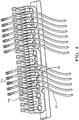
- the first and second retaining fingers 14a, 14b are configured to receive and releasably retain an elongate article 20, such as a wire cable, within the retaining channel 18 as illustrated in Fig. 4 .
- the first and second retaining fingers 14a, 14b have rounded corners and edges to minimize the likelihood of damage to the elongate element 20 as it is inserted into and removed from the retaining channel 18.
- releasable fasteners such as cam fasteners may be used to secure the first and second retainer modules to one another.
- a non-releasable fastening device such as an adhesive or rivet may be used to secure the first and second retainer modules to one another.
- the first retainer module 12a is the same as the second retainer module 12b. i.e. they may be substantially dimensionally indistinguishable from one another. As used herein "substantially dimensionally indistinguishable” means that the dimensions of the first and second retainer modules 12a, 12b are the same within the manufacturing tolerances of the process used to manufacture the retainer modules when using the same manufacturing process.
- the first retainer module 12a may alternatively be dimensionally identical to the second retainer module 12b.
- dimensionally identical means that the dimensions of the first and second retainer modules 12a, 12b are identical within the manufacturing tolerances of the process used to manufacture the retainer modules when using the same tooling.
- the first and second retainer modules 12a, 12b are formed from a polymeric material, such as a glass filled polyamide (nylon) material, using a molding process and the first retainer module 12a in formed in the same mold cavity as the second retainer module 12b, thereby providing a first retainer module 12a that is dimensionally identical to the second retainer module 12b.
- a polymeric material such as a glass filled polyamide (nylon) material
- Each retainer module 12 includes a retaining finger 14 having a base portion 22 and a flexible finger portion 24 extending from the base portion 22.
- the finger portion 24 has a first arcuate section 26 located proximate the base portion 22 and a second arcuate section 28 curving in a direction opposite the first arcuate section 26.
- the second arcuate section 28 is located proximate a tip 30 of the finger portion 24.
- a radius of curvature of the first arcuate section 26 is greater than a radius of curvature of the second arcuate section 28.
- the retainer module 12 also includes an attachment portion 32 extending from the base portion 22 in a direction opposite the finger portion 24.
- the attachment portion 32 has an inner surface 34 and an outer surface 36 opposite the inner surface 34.
- a thickness of the attachment portion 32 is less than a thickness of the base portion 22. According to this example implementation, the thickness of the attachment portion 32 is about half of the thickness of the base portion 22.
- the retainer module 12 includes a plurality of the base portions and a plurality of the finger portions. The base portion 22 overhangs the inner surface 34 of the attachment portion 32.
- the attachment portion 32 defines a first aperture 38 and a second aperture 40, each extending therethrough from the inner surface 34 to the outer surface 36.
- the first aperture 38 and the second aperture 40 are equidistant from a centerline 42 of the attachment portion 32, thereby allowing the retainer module 12 to be used as a first retainer module 12a or a second retainer module 12b in the modular retainer assembly 10.
- the outer surface 36 defines a first countersunk area 44 surrounding the first aperture 38 and a second countersunk area 46 surrounding the second aperture 40 in which the head of the socket head screw 16a or hex nut 16b is received.
- the first and second apertures 38, 40 are sized to inhibit rotation of the hex nut 16b when the socket head screw 16a is turned to tighten or loosen the screw 16a.
- the inner surface 34 defines a first alignment feature 48 protruding from the inner surface 34 and a second alignment feature 50 indented into the inner surface 34.
- the first alignment feature 48 and the second alignment feature 50 are equidistant from the centerline 42 of the attachment portion 32, thereby allowing the retainer module 12 to be used as a first retainer module 12a or a second retainer module 12b in the modular retainer assembly 10.
- the first retainer module 12a is mated with the second retainer module 12b
- the first alignment feature 48 of the first retainer module 12a is received within the second alignment feature 50 of the second retainer module 12b and the first alignment feature 48 of the second retainer module 12b is received within the second alignment feature 50 of the first retainer module 12a.
- the first alignment feature 48 has a different cross-sectional shape than the second alignment feature 50, i.e. round vs. diamond shape.
- the first alignment feature 48 is sized such that it may be received within the second alignment feature 50.
- the first and second alignment features may have the same cross-sectional shape.
- the first and second alignment features of the first retainer module may have different shapes than the first and second alignment features of the second retainer module, however in this case the first and second retainer modules would not be interchangeable.
- the retainer module 12 also defines a hemicylindrical channel 52 in the inner surface 34 extending to a rectangular aperture 54 extending through the attachment portion 32 from the inner surface 34 to the outer surface 36.
- the hemicylindrical channels 52 form a cylindrical passage in which another fastener may be received to attach the modular retainer assembly 10 to a support structure as shown in Fig. 4 .
- another screw 16a is inserted within the passage and a hex nut 16b is disposed within the aperture.
- the aperture is sized to inhibit rotation of the hex nut 16b when the screw 16a is turned to tighten or loosen the screw 16a.
- the modular retainer assembly 10 may be used to retain wire cables 20 in a wire transport pallet as shown in Fig. 4 .
- a wire transport pallet may be used while manufacturing wire harness assemblies to move wires between machines that apply terminals to the ends of the wire cables and machines that insert the terminals into electrical connector housings.
- While the illustrated examples are configured to secure a wire cable, alternative implementations may be used to secure other elongate articles such as hydraulic hoses, pneumatic tubing, fiber optic cables, conduits, vines, harnesses, etc., to a supporting structure.
- Fig. 6 illustrates a method 200 of method 200 of retaining an elongate article 20.
- the method 200 includes the following steps:
- STEP 202 PROVIDE A FIRST RETAINER MODULE AND A SECOND RETAINER MODULE, includes providing a first retainer module 12a and a second retainer module 12b, the first and second retainer modules 12a, 12b each having a base portion 22, a finger portion 24 extending from the base portion 22 having a first arcuate section 26 proximate the base portion 22 and a second arcuate section 28 curving in a direction opposite the first arcuate section 26 proximate a tip 30 of the finger portion 24, and an attachment portion 32 extending from the base portion 22 in a direction opposite the finger portion 24, wherein the attachment portion 32 has an inner surface 34 and an outer surface 36 opposite the inner surface 34 and wherein a thickness of the attachment portion 32 is less than a thickness of the base portion 22;
- STEP 204 SECURE THE FIRST RETAINER MODULE TO THE SECOND RETAINER MODULE SUCH THAT AN INNER SURFACE OF THE FIRST RETAINER MODULE IS IN CONTACT WITH AN INNER SURFACE OF THE SECOND RETAINER MODULE, includes securing the first retainer module 12a to the second retainer module 12b such that the inner surface 34 of the first retainer module 12a is in contact with the inner surface 34 of the second retainer module 12b; and
- STEP 206 includes disposing the elongate article 20 between the finger portions of the first and second retainer modules 12a, 12b.
- the elongate article 20 is a wire cable.
- a modular retainer assembly 10 and a retainer module 12 is presented.
- the modular terminal assembly provides the benefit of being service able allowing replacement of one of the retainer modules 12a, 12b if a retainer finger 14 is broken rather than replacing the entire modular retainer assembly 10.
- the retainer module 12 also provides the benefit of forming the modular retainer assembly 10 with as few as three separate parts, the retainer module 12, the screw, and the nut, thereby minimizing the part count for the assembly.
- the retainer module 12 also simplifies the tooling required to make the modular retainer assembly 10 because the retainer modules may be made from a single mold cavity design. Consistent shapes of the retaining fingers 14 and consistent spring forces provided by the retaining fingers 14 may be achieved with tight molding tolerances.
- the modular retainer assembly 10 will accommodate elongate articles 20 with a wide range of cross section areas, e.g. 0.75 mm 2 to 2.0 mm 2 .
- the design of the retainer module 12 may be easily modified to adjust engagement and retention forces, if needed.
- a method 200 of retaining an elongate article 20 using the modular retainer assembly 10 is also presented.
- 'one or more' includes a function being performed by one element, a function being performed by more than one element, e.g., in a distributed fashion, several functions being performed by one element, several functions being performed by several elements, or any combination of the above.
- first, second, etc. are, in some instances, used herein to describe various elements, these elements should not be limited by these terms. These terms are only used to distinguish one element from another.
- a first contact could be termed a second contact, and, similarly, a second contact could be termed a first contact, without departing from the scope of the various described implementations.
- the first contact and the second contact are both contacts, but they are not the same contact.
- the term “if' is, optionally, construed to mean “when” or “upon” or “in response to determining” or “in response to detecting,” depending on the context.
- the phrase “if it is determined” or “if [a stated condition or event] is detected” is, optionally, construed to mean “upon determining” or “in response to determining” or “upon detecting [the stated condition or event]” or “in response to detecting [the stated condition or event],” depending on the context.
Landscapes
- Engineering & Computer Science (AREA)
- General Engineering & Computer Science (AREA)
- Mechanical Engineering (AREA)
- Architecture (AREA)
- Civil Engineering (AREA)
- Structural Engineering (AREA)
- Supports For Pipes And Cables (AREA)
- Moulds For Moulding Plastics Or The Like (AREA)
- Package Frames And Binding Bands (AREA)
- Installation Of Indoor Wiring (AREA)
Abstract
Description
- The invention generally relates to a modular retainer assembly configured to retain an elongate article, such as an electrical cable.
- The present invention will now be described, by way of example with reference to the accompanying drawings, in which:
-
Fig. 1 is a perspective view of a modular retainer assembly according to one implementation of the invention; -
Fig. 2 is an exploded perspective view of the modular retainer assembly ofFig. 1 according to one implementation of the invention; -
Fig. 3 is a perspective view of the modular retainer assembly ofFig. 1 according to one implementation of the invention; -
Fig. 4 is a wiring transport pallet in which wire cables are retaining by the modular retainer assembly ofFig. 1 according to one implementation of the invention; and -
Fig. 5A is a front view of a retainer module of the modular retainer assembly ofFig. 1 according to one implementation of the invention; -
Fig. 5B is a bottom view of the retainer module ofFig. 5A according to one implementation of the invention; -
Fig. 5C is a side view of the retainer module ofFig. 5A according to one implementation of the invention; -
Fig. 6 is a flow chart of a method of retaining an elongate article according to another implementation of the invention. - According to one implementation of the invention, a modular retainer assembly is provided. The modular retainer assembly includes a first retainer module defining a flexible first retaining finger and a second retainer module that is distinct from and joined to the first retaining module. The second retainer module defines a flexible second retaining finger. When the first and second retainer modules are mated together, the first retaining finger is arranged opposite the second retaining finger. The first and second retaining fingers are configured to receive and retain an elongate article between them.
- An example implementation having one or more features of the modular retainer assembly of the previous paragraph further includes a fastening device configured to secure the first retainer module to the second retainer module.
- In an example implementation having one or more features of the modular retainer assembly of the previous paragraph, the fastening device is further configured to release the first retainer module from to the second retainer module.
- In an example implementation having one or more features of the modular retainer assembly of the previous paragraph, the first retainer module is substantially dimensionally indistinguishable from the second retainer module.
- In an example implementation having one or more features of the modular retainer assembly of the previous paragraph, the first retainer module is dimensionally identical to the second retainer module.
- In an example implementation having one or more features of the modular retainer assembly of the previous paragraph, the first and second retainer modules are formed of a polymeric material using a molding process and the first retainer module may be formed form the same mold cavity as the second retainer module.
- In an example implementation having one or more features of the modular retainer assembly of the previous paragraph, the elongate article is a wire cable.
- According to another implementation of the invention, a retainer module is provided. The retainer module includes a base portion and a flexible finger portion extending from the base portion having a first arcuate section located proximate the base portion and a second arcuate section curving in a direction opposite the first arcuate section. The second arcuate section is located proximate a tip of the finger portion. The retainer module also includes an attachment portion extending from the base portion in a direction opposite the finger portion. The attachment portion has an inner surface and an outer surface opposite the inner surface. A thickness of the attachment portion is less than a thickness of the base portion.
- An example implementation having one or more features of the retainer module of the previous paragraph further includes a plurality of the base portions and a plurality of the finger portions.
- In an example implementation having one or more features of the retainer module of the previous paragraph, the thickness of the attachment portion is about half of the thickness of the base portion.
- In an example implementation having one or more features of the retainer module of the previous paragraph, the retainer module is formed of a polymeric material.
- In an example implementation having one or more features of the retainer module of the previous paragraph, a radius of curvature of the first arcuate section is greater than a radius of curvature of the second arcuate section.
- In an example implementation having one or more features of the retainer module of the previous paragraph, the base portion overhangs the inner surface of the attachment portion.
- In an example implementation having one or more features of the retainer module of the previous paragraph, the attachment portion defines a first aperture and a second aperture, each extending therethrough from the inner surface to the outer surface. The first aperture and the second aperture are equidistant from a centerline of the attachment portion.
- In an example implementation having one or more features of the retainer module of the previous paragraph, the inner surface defines a first alignment feature protruding from the inner surface and a second alignment feature indented into the inner surface. The first alignment feature and the second alignment feature are equidistant from the centerline of the attachment portion.
- In an example implementation having one or more features of the retainer module of the previous paragraph, the first alignment feature has a different cross-sectional shape than the second alignment feature.
- In an example implementation having one or more features of the retainer module of the previous paragraph, the outer surface defines a first countersunk area surrounding the first aperture and a second countersunk area surrounding the second aperture.
- According to yet another implementation of the invention, a modular retainer assembly is provided. The modular retainer assembly includes a first retainer module having one or more features of the retainer module of the previous paragraph and a second retainer module having one or more features of the retainer module of the previous paragraph. The first alignment feature of the first retainer module is received within the second alignment feature of the second retainer module and the first alignment feature of the second retainer module is received within the second alignment feature of the first retainer module.
- An example implementation having one or more features of the modular retainer assembly of the previous paragraph further includes a first fastening device disposed in the first aperture and a second fastening device disposed in the second aperture, each in compressive contact with the outer surfaces of the first and second retainer modules, thereby securing the first retainer module to the second retainer module.
- In an example implementation having one or more features of the modular retainer assembly of the previous paragraph, the first and second fastening devices are threaded fasteners having a screw with a head and a nut. The heads and the nuts are contained within the first or second countersunk areas.
- In an example implementation having one or more features of the modular retainer assembly of the previous paragraph, the first retainer module is substantially dimensionally indistinguishable the second retainer module.
- According to one more implementation of the invention, a method of retaining an elongate article is provided. The method includes the step of providing a first retainer module and a second retainer module, the first and second retainer modules each having a base portion, a flexible finger portion extending from the base portion having a first arcuate section proximate the base portion and a second arcuate section curving in a direction opposite the first arcuate section proximate a tip of the finger portion, and an attachment portion extending from the base portion in a direction opposite the finger portion, wherein the attachment portion has an inner surface and an outer surface opposite the inner surface and wherein a thickness of the attachment portion is less than a thickness of the base portion. The method further includes the step of securing the first retainer module to the second retainer module such that the inner surface of the first retainer module is in contact with the inner surface of the second retainer module.
- An example implementation having one or more features of the method of the previous paragraph further includes the step of disposing the elongate article between the finger portions of the first and second retainer modules.
- In an example implementation having one or more features of the method of the previous paragraph, the elongate article is a wire cable.
- Reference will now be made in detail to implementations, examples of which are illustrated in the accompanying drawings. In the following detailed description, numerous specific details are set forth in order to provide a thorough understanding of the various described implementations. However, it will be apparent to one of ordinary skill in the art that the various described implementations may be practiced without these specific details. In other instances, well-known methods, procedures, components, circuits, and networks have not been described in detail so as not to unnecessarily obscure aspects of the implementations.
-
Figs. 1-3 illustrate a non-limiting example of amodular retainer assembly 10 according to one or more implementations of the invention. Themodular retainer assembly 10 includes afirst retainer module 12a and asecond retainer module 12b that is separate and distinct from thefirst retainer module 12a. Thefirst retainer module 12a defines a flexible first retainingfinger 14a and thesecond retainer module 12b defines a flexible second retainingfinger 14b. Thesecond retainer module 12b is joined and secured to thefirst retaining module 12a by a releasable fastening device, e.g. a pair ofsocket head screws 16a andhex nuts 16b. As the first andsecond retainer modules finger 14a is arranged so that it is located opposite the second retainingfinger 14b, thereby forming aretaining channel 18 between them. The first and second retainingfingers elongate article 20, such as a wire cable, within theretaining channel 18 as illustrated inFig. 4 . The first and second retainingfingers elongate element 20 as it is inserted into and removed from the retainingchannel 18. - In alternative implementations, other releasable fasteners, such as cam fasteners may be used to secure the first and second retainer modules to one another. In yet other alternative implementations, a non-releasable fastening device such as an adhesive or rivet may be used to secure the first and second retainer modules to one another.
- The
first retainer module 12a is the same as thesecond retainer module 12b. i.e. they may be substantially dimensionally indistinguishable from one another. As used herein "substantially dimensionally indistinguishable" means that the dimensions of the first andsecond retainer modules first retainer module 12a may alternatively be dimensionally identical to thesecond retainer module 12b. As used herein "dimensionally identical" means that the dimensions of the first andsecond retainer modules - In one implementation, the first and
second retainer modules first retainer module 12a in formed in the same mold cavity as thesecond retainer module 12b, thereby providing afirst retainer module 12a that is dimensionally identical to thesecond retainer module 12b. - A non-limiting example of a
retainer module 12 is illustrated inFigs. 5A-5C . Eachretainer module 12 includes a retainingfinger 14 having abase portion 22 and aflexible finger portion 24 extending from thebase portion 22. Thefinger portion 24 has a firstarcuate section 26 located proximate thebase portion 22 and a secondarcuate section 28 curving in a direction opposite the firstarcuate section 26. The secondarcuate section 28 is located proximate atip 30 of thefinger portion 24. A radius of curvature of the firstarcuate section 26 is greater than a radius of curvature of the secondarcuate section 28. - The
retainer module 12 also includes anattachment portion 32 extending from thebase portion 22 in a direction opposite thefinger portion 24. Theattachment portion 32 has aninner surface 34 and anouter surface 36 opposite theinner surface 34. A thickness of theattachment portion 32 is less than a thickness of thebase portion 22. According to this example implementation, the thickness of theattachment portion 32 is about half of the thickness of thebase portion 22. Further according to this example implementation, theretainer module 12 includes a plurality of the base portions and a plurality of the finger portions. Thebase portion 22 overhangs theinner surface 34 of theattachment portion 32. - The
attachment portion 32 defines afirst aperture 38 and asecond aperture 40, each extending therethrough from theinner surface 34 to theouter surface 36. Thefirst aperture 38 and thesecond aperture 40 are equidistant from acenterline 42 of theattachment portion 32, thereby allowing theretainer module 12 to be used as afirst retainer module 12a or asecond retainer module 12b in themodular retainer assembly 10. Theouter surface 36 defines a first countersunkarea 44 surrounding thefirst aperture 38 and a second countersunkarea 46 surrounding thesecond aperture 40 in which the head of thesocket head screw 16a orhex nut 16b is received. The first andsecond apertures hex nut 16b when thesocket head screw 16a is turned to tighten or loosen thescrew 16a. - The
inner surface 34 defines afirst alignment feature 48 protruding from theinner surface 34 and asecond alignment feature 50 indented into theinner surface 34. Thefirst alignment feature 48 and thesecond alignment feature 50 are equidistant from thecenterline 42 of theattachment portion 32, thereby allowing theretainer module 12 to be used as afirst retainer module 12a or asecond retainer module 12b in themodular retainer assembly 10. As thefirst retainer module 12a is mated with thesecond retainer module 12b, thefirst alignment feature 48 of thefirst retainer module 12a is received within thesecond alignment feature 50 of thesecond retainer module 12b and thefirst alignment feature 48 of thesecond retainer module 12b is received within thesecond alignment feature 50 of thefirst retainer module 12a. - In the illustrated example implementation, the
first alignment feature 48 has a different cross-sectional shape than thesecond alignment feature 50, i.e. round vs. diamond shape. Thefirst alignment feature 48 is sized such that it may be received within thesecond alignment feature 50. In alternative embodiments, the first and second alignment features may have the same cross-sectional shape. In other alternative embodiments, the first and second alignment features of the first retainer module may have different shapes than the first and second alignment features of the second retainer module, however in this case the first and second retainer modules would not be interchangeable. - The
retainer module 12 also defines ahemicylindrical channel 52 in theinner surface 34 extending to arectangular aperture 54 extending through theattachment portion 32 from theinner surface 34 to theouter surface 36. When thefirst retainer module 12a is mated with thesecond retainer module 12b, thehemicylindrical channels 52 form a cylindrical passage in which another fastener may be received to attach themodular retainer assembly 10 to a support structure as shown inFig. 4 . As shown in the example ofFig. 1 , anotherscrew 16a is inserted within the passage and ahex nut 16b is disposed within the aperture. The aperture is sized to inhibit rotation of thehex nut 16b when thescrew 16a is turned to tighten or loosen thescrew 16a. - The
modular retainer assembly 10 may be used to retainwire cables 20 in a wire transport pallet as shown inFig. 4 . Such a wire transport pallet may be used while manufacturing wire harness assemblies to move wires between machines that apply terminals to the ends of the wire cables and machines that insert the terminals into electrical connector housings. - While the illustrated examples are configured to secure a wire cable, alternative implementations may be used to secure other elongate articles such as hydraulic hoses, pneumatic tubing, fiber optic cables, conduits, vines, harnesses, etc., to a supporting structure.
-
Fig. 6 illustrates amethod 200 ofmethod 200 of retaining anelongate article 20. Themethod 200 includes the following steps: -
STEP 202, PROVIDE A FIRST RETAINER MODULE AND A SECOND RETAINER MODULE, includes providing afirst retainer module 12a and asecond retainer module 12b, the first andsecond retainer modules base portion 22, afinger portion 24 extending from thebase portion 22 having a firstarcuate section 26 proximate thebase portion 22 and a secondarcuate section 28 curving in a direction opposite the firstarcuate section 26 proximate atip 30 of thefinger portion 24, and anattachment portion 32 extending from thebase portion 22 in a direction opposite thefinger portion 24, wherein theattachment portion 32 has aninner surface 34 and anouter surface 36 opposite theinner surface 34 and wherein a thickness of theattachment portion 32 is less than a thickness of thebase portion 22; -
STEP 204, SECURE THE FIRST RETAINER MODULE TO THE SECOND RETAINER MODULE SUCH THAT AN INNER SURFACE OF THE FIRST RETAINER MODULE IS IN CONTACT WITH AN INNER SURFACE OF THE SECOND RETAINER MODULE, includes securing thefirst retainer module 12a to thesecond retainer module 12b such that theinner surface 34 of thefirst retainer module 12a is in contact with theinner surface 34 of thesecond retainer module 12b; and -
STEP 206, DISPOSE AN ELONGATE ARTICLE BETWEEN FINGER PORTIONS OF THE FIRST AND SECOND RETAINER MODULES, includes disposing theelongate article 20 between the finger portions of the first andsecond retainer modules elongate article 20 is a wire cable. - Accordingly, a
modular retainer assembly 10 and aretainer module 12 is presented. The modular terminal assembly provides the benefit of being service able allowing replacement of one of theretainer modules retainer finger 14 is broken rather than replacing the entiremodular retainer assembly 10. Theretainer module 12 also provides the benefit of forming themodular retainer assembly 10 with as few as three separate parts, theretainer module 12, the screw, and the nut, thereby minimizing the part count for the assembly. Theretainer module 12 also simplifies the tooling required to make themodular retainer assembly 10 because the retainer modules may be made from a single mold cavity design. Consistent shapes of the retainingfingers 14 and consistent spring forces provided by the retainingfingers 14 may be achieved with tight molding tolerances. Themodular retainer assembly 10 will accommodateelongate articles 20 with a wide range of cross section areas, e.g. 0.75 mm2 to 2.0 mm2. The design of theretainer module 12 may be easily modified to adjust engagement and retention forces, if needed. Amethod 200 of retaining anelongate article 20 using themodular retainer assembly 10 is also presented. - While this invention has been described in terms of the preferred implementations thereof, it is not intended to be so limited, but rather only to the extent set forth in the claims that follow. For example, the above-described implementations (and/or aspects thereof) may be used in combination with each other. In addition, many modifications may be made to configure a particular situation or material to the teachings of the invention without departing from its scope. Dimensions, types of materials, orientations of the various components, and the number and positions of the various components described herein are intended to define parameters of certain implementations, and are by no means limiting and are merely prototypical implementations.
- Many other implementations and modifications within the spirit and scope of the claims will be apparent to those of skill in the art upon reviewing the above description. The scope of the invention should, therefore, be determined with reference to the following claims, along with the full scope of equivalents to which such claims are entitled.
- As used herein, 'one or more' includes a function being performed by one element, a function being performed by more than one element, e.g., in a distributed fashion, several functions being performed by one element, several functions being performed by several elements, or any combination of the above.
- It will also be understood that, although the terms first, second, etc. are, in some instances, used herein to describe various elements, these elements should not be limited by these terms. These terms are only used to distinguish one element from another. For example, a first contact could be termed a second contact, and, similarly, a second contact could be termed a first contact, without departing from the scope of the various described implementations. The first contact and the second contact are both contacts, but they are not the same contact.
- The terminology used in the description of the various described implementations herein is for the purpose of describing particular implementations only and is not intended to be limiting. As used in the description of the various described implementations and the appended claims, the singular forms "a", "an" and "the" are intended to include the plural forms as well, unless the context clearly indicates otherwise. It will also be understood that the term "and/or" as used herein refers to and encompasses any and all possible combinations of one or more of the associated listed items. It will be further understood that the terms "includes," "including," "comprises," and/or "comprising," when used in this specification, specify the presence of stated features, integers, steps, operations, elements, and/or components, but do not preclude the presence or addition of one or more other features, integers, steps, operations, elements, components, and/or groups thereof.
- As used herein, the term "if' is, optionally, construed to mean "when" or "upon" or "in response to determining" or "in response to detecting," depending on the context. Similarly, the phrase "if it is determined" or "if [a stated condition or event] is detected" is, optionally, construed to mean "upon determining" or "in response to determining" or "upon detecting [the stated condition or event]" or "in response to detecting [the stated condition or event]," depending on the context.
- Additionally, while terms of ordinance or orientation may be used herein these elements should not be limited by these terms. All terms of ordinance or orientation, unless stated otherwise, are used for purposes distinguishing one element from another, and do not denote any particular order, order of operations, direction or orientation unless stated otherwise.
Claims (13)
- A retainer module (12), comprising:a base portion (22);a flexible finger portion (24) extending from the base portion (22) and having a first arcuate section (26) located proximate the base portion (22) and a second arcuate section (28) curving in a direction opposite the first arcuate section (26), the second arcuate section (28) located proximate a tip (30) of the finger portion (24); andan attachment portion (32) extending from the base portion (22) in a direction opposite the finger portion (24), wherein the attachment portion (32) has an inner surface (34) and an outer surface (36) opposite the inner surface (34) and wherein a thickness of the attachment portion (32) is less than a thickness of the base portion (22).
- The retainer module (12) according to claim 1, wherein the retainer module (12) further comprises a plurality of the base portions (22) and a plurality of the finger portions (24).
- The retainer module (12) according to claim 1 or 2, wherein the thickness of the attachment portion (32) is about half of the thickness of the base portion (22).
- The retainer module (12) according to any one of the preceding claims, wherein the retainer module (12) is formed of a polymeric material.
- The retainer module (12) according to any one of the preceding claims, wherein a radius of curvature of the first arcuate section (26) is greater than a radius of curvature of the second arcuate section (28).
- The retainer module (12) according to any one of the preceding claims, wherein the base portion (22) overhangs the inner surface (34) of the attachment portion (32).
- The retainer module (12) according to claim 6, wherein the attachment portion (32) defines a first aperture (38) and a second aperture (40), each extending therethrough from the inner surface (34) to the outer surface (36) and wherein the first aperture (38) and the second aperture (40) are equidistant from a centerline (42) of the attachment portion (32).
- The retainer module (12) according to claim 7, wherein the inner surface (34) defines a first alignment feature (48) protruding from the inner surface (34) and a second alignment feature (50) indented into the inner surface (34) and wherein the first alignment feature (48) and the second alignment feature (50) are equidistant from the centerline (42) of the attachment portion (32).
- The retainer module (12) according to claim 8, wherein the first alignment feature (48) has a different cross-sectional shape than the second alignment feature (50).
- The retainer module (12) according to claim 9, wherein the outer surface (36) defines a first countersunk area (44) surrounding the first aperture (38) and a second countersunk area (46) surrounding the second aperture (40).
- A method (200) of retaining an elongate article (20), comprising the steps of:providing a first retainer module (12a) and a second retainer module (12b), the first and second retainer modules (12a, 12b) each having:a base portion (22),a flexible finger portion (24) extending from the base portion (22) and having a first arcuate section (26) proximate the base portion (22) and a second arcuate section (28) curving in a direction opposite the first arcuate section (26) proximate a tip (30) of the finger portion (24), andan attachment portion (32) extending from the base portion (22) in a direction opposite the finger portion (24), wherein the attachment portion (32) has an inner surface (34) and an outer surface (36) opposite the inner surface (34) and wherein a thickness of the attachment portion (32) is less than a thickness of the base portion (22); andsecuring the first retainer module (12a) to the second retainer module (12b) such that the inner surface (34) of the first retainer module (12a) is in contact with the inner surface (34) of the second retainer module (12b).
- The method (200) according to claim 11, further comprising the step of:
disposing the elongate article (20) between the finger portions of the first and second retainer modules (12a, 12b). - The method (200) according to claim 11 or 12, wherein the elongate article (20) is a wire cable.
Applications Claiming Priority (1)
| Application Number | Priority Date | Filing Date | Title |
|---|---|---|---|
| US16/397,417 US10907750B2 (en) | 2019-04-29 | 2019-04-29 | Modular retainer assembly |
Publications (2)
| Publication Number | Publication Date |
|---|---|
| EP3734779A1 true EP3734779A1 (en) | 2020-11-04 |
| EP3734779B1 EP3734779B1 (en) | 2024-06-05 |
Family
ID=70390755
Family Applications (1)
| Application Number | Title | Priority Date | Filing Date |
|---|---|---|---|
| EP20170267.7A Active EP3734779B1 (en) | 2019-04-29 | 2020-04-19 | Modular retainer assembly |
Country Status (4)
| Country | Link |
|---|---|
| US (2) | US10907750B2 (en) |
| EP (1) | EP3734779B1 (en) |
| CN (1) | CN111864655B (en) |
| PL (1) | PL3734779T3 (en) |
Citations (2)
| Publication number | Priority date | Publication date | Assignee | Title |
|---|---|---|---|---|
| KR20020085709A (en) * | 2001-05-10 | 2002-11-16 | 김명대 | Cable holder for supporting a communication cable |
| DE202004013412U1 (en) * | 2004-08-27 | 2004-10-28 | CCS Technology, Inc., Wilmington | cable clip |
Family Cites Families (45)
| Publication number | Priority date | Publication date | Assignee | Title |
|---|---|---|---|---|
| GB303990A (en) * | 1927-12-07 | 1929-01-17 | Boyd Neil Robert Lamont | An improved clamp or holdfast for pipes and tubes |
| DE509529C (en) * | 1929-04-18 | 1930-10-09 | Carl Pegelow | Fastening clamp, especially for laying electrical cables and pipes |
| GB952164A (en) * | 1959-03-10 | 1964-03-11 | Cable Supports Ltd | Improvements in or relating to hangers for elongated members such as electric cables or pipes |
| FR1250380A (en) * | 1960-03-09 | 1961-01-06 | Support device for cables, pipes and other elongated elements | |
| GB959109A (en) * | 1961-06-19 | 1964-05-27 | Sankey Sheldon Ltd | Improvements relating to cleats or clamps for supporting cables, pipes and the like |
| DE1167607B (en) * | 1962-03-19 | 1964-04-09 | Gasturbinenbau Und Energiemasc | Pipe clamp |
| JPS5149501Y2 (en) * | 1973-12-05 | 1976-11-29 | ||
| GB1468823A (en) * | 1974-05-24 | 1977-03-30 | Bicc Ltd | Electric cable cleat |
| US4029277A (en) | 1976-03-15 | 1977-06-14 | Panduit Corporation | Apparatus for holding and forming a plurality of objects into a bundle |
| JPS5547081A (en) * | 1978-09-27 | 1980-04-02 | Puresuto Kogyo Kenkyusho Kk | Fitting metal for pipe |
| JPS60855Y2 (en) * | 1981-06-10 | 1985-01-11 | ワイケイケイ株式会社 | Thread presser tension device for sewing machine |
| US4431152A (en) * | 1981-12-10 | 1984-02-14 | Square D Company | Adjustable cable restraint assembly |
| JPH06855Y2 (en) * | 1988-08-10 | 1994-01-05 | 北川工業株式会社 | Wire clamp |
| DE9011879U1 (en) * | 1990-08-16 | 1990-10-18 | A. Raymond KG, 7850 Lörrach | Vibration-damping fastening element for pipelines |
| DE4432781A1 (en) * | 1994-09-15 | 1996-03-21 | Hilti Ag | Pipe and cable clamp with foot section and mounting bracket |
| US5884372A (en) * | 1997-08-04 | 1999-03-23 | National Molding Corporation | Refreshment tube retaining device |
| US6602016B2 (en) * | 2000-04-18 | 2003-08-05 | Hkx Inc. | Hydraulic line mounting clamp |
| FR2820189B1 (en) * | 2001-01-29 | 2004-01-16 | Willy Es | COLLAR FOR HOLDING TUBES, PIPES OR THE LIKE FINDING AN APPLICATION IN THE FIELD OF PLUMBING |
| US6669150B2 (en) * | 2001-05-31 | 2003-12-30 | Illinois Tool Works Inc. | Clip assembly with positive locating features |
| US20070128939A1 (en) * | 2004-05-10 | 2007-06-07 | Andrew Corporation | Stackable Cable Hanger |
| US7152831B2 (en) * | 2004-11-23 | 2006-12-26 | The Lamson & Sessions Co. | Conduit support |
| FR2885670A1 (en) * | 2005-05-10 | 2006-11-17 | P D C I Sarl | Tube or cable fixing clip, has locking system placed below clamp retained by strips fixed to arms by hinges, where clamp has central hole arranged to pass tool for driving pin to wall by simple force exerted in another hole formed in base |
| DE102005025679A1 (en) * | 2005-06-03 | 2006-12-07 | A. Raymond Et Cie | Device for holding at least one elongated object |
| US7315680B1 (en) * | 2006-06-21 | 2008-01-01 | Adc Telecommunications, Inc. | Cable routing devices with integrated couplers |
| GB0624617D0 (en) * | 2006-12-11 | 2007-01-17 | Tyco Electronics Raychem Nv | Cable Retention Clip |
| TWI365331B (en) * | 2007-06-15 | 2012-06-01 | Au Optronics Corp | Lamp support structure |
| DE602008004736D1 (en) * | 2008-03-28 | 2011-03-10 | Purus Ab | pipe clamp |
| US20100258684A1 (en) * | 2009-04-14 | 2010-10-14 | Guillaume Hugo Marquis-Martin | Support for tubing and method of using same |
| US20100258685A1 (en) * | 2009-04-14 | 2010-10-14 | Gardner Michael J | Utility holder |
| JP5602944B2 (en) * | 2010-05-17 | 2014-10-08 | ボルボ コンストラクション イクイップメント アーベー | Hydraulic piping fixing device for construction machinery |
| US8070111B1 (en) * | 2010-05-20 | 2011-12-06 | Charles Zeller | Electrical cord cleat |
| DE102010039135B4 (en) * | 2010-08-10 | 2013-11-07 | Airbus Operations Gmbh | Aerial or spacecraft with a device for supporting systems |
| FR2964712B1 (en) * | 2010-09-09 | 2013-11-01 | Raymond A & Cie | DEVICE FOR FIXING AT LEAST ONE ELONGATED MEMBER ON A SUPPORT |
| US9206927B2 (en) * | 2012-05-18 | 2015-12-08 | Brian K. Carter | Utility conduit supporting device, system, and method |
| US9698529B1 (en) * | 2013-02-28 | 2017-07-04 | Amazon Technologies, Inc. | Cable holder for system serviceabilty |
| FR3006412B1 (en) * | 2013-05-28 | 2015-06-12 | Snecma | DEVICE FOR DETECTING EXTENDED SHAPE ELEMENTS OF AN AIRCRAFT TURBOMACHINE |
| CN204905781U (en) * | 2015-09-10 | 2015-12-23 | 杨昌松 | A elasticity fastener for distribution |
| ITUB20154200A1 (en) * | 2015-10-07 | 2017-04-07 | Fi Mo Tec Spa | IMPROVED TYPE DEVICE FOR FIXING CABLES, TUBES AND OTHER LONG-RANGE BODIES WITH A DIFFERENTIAL DIAMETER |
| JP2017137905A (en) * | 2016-02-02 | 2017-08-10 | ポップリベット・ファスナー株式会社 | Clip/clamp assembly and attachment structure |
| US20170284592A1 (en) * | 2016-03-30 | 2017-10-05 | Timothy P. Stender | Twist-base mount |
| DE202017107545U1 (en) * | 2017-12-12 | 2019-03-18 | A. Raymond Et Cie Scs | mounting bracket |
| CN208112127U (en) * | 2018-04-11 | 2018-11-16 | 天津市朗博电子有限公司 | A kind of easy-to-mount beam wire clamp |
| US10903633B2 (en) * | 2018-06-07 | 2021-01-26 | Panduit Corp. | Interlocking cable cleat |
| US10439381B1 (en) * | 2018-07-10 | 2019-10-08 | The Boeing Company | Electrical raceway system and associated wire bundle clamp system and method |
| US10690267B2 (en) * | 2018-07-16 | 2020-06-23 | Raytheon Technologies Corporation | Adjustable holding assembly |
-
2019
- 2019-04-29 US US16/397,417 patent/US10907750B2/en active Active
-
2020
- 2020-04-19 PL PL20170267.7T patent/PL3734779T3/en unknown
- 2020-04-19 EP EP20170267.7A patent/EP3734779B1/en active Active
- 2020-04-28 CN CN202010348782.3A patent/CN111864655B/en active Active
- 2020-12-14 US US17/121,483 patent/US11339898B2/en active Active
Patent Citations (3)
| Publication number | Priority date | Publication date | Assignee | Title |
|---|---|---|---|---|
| KR20020085709A (en) * | 2001-05-10 | 2002-11-16 | 김명대 | Cable holder for supporting a communication cable |
| KR100388855B1 (en) * | 2001-05-10 | 2003-06-25 | 김명대 | Cable holder for supporting a communication cable |
| DE202004013412U1 (en) * | 2004-08-27 | 2004-10-28 | CCS Technology, Inc., Wilmington | cable clip |
Non-Patent Citations (1)
| Title |
|---|
| "ONLINE KATALOG DER FIRMA RICHCO INC, KATALOGNUMMER OFB-BH-6-19 O.F. (BRACKET BLIND HOLE SERIES)", INTERNET CITATION, 14 November 2005 (2005-11-14), XP002355043, Retrieved from the Internet <URL:http://www.richco-inc.com/group_details.asp?seccode=350&grpcode=130> [retrieved on 20051114] * |
Also Published As
| Publication number | Publication date |
|---|---|
| PL3734779T3 (en) | 2024-10-07 |
| CN111864655A (en) | 2020-10-30 |
| EP3734779B1 (en) | 2024-06-05 |
| CN111864655B (en) | 2021-12-10 |
| US20200340601A1 (en) | 2020-10-29 |
| US20210095789A1 (en) | 2021-04-01 |
| US10907750B2 (en) | 2021-02-02 |
| US11339898B2 (en) | 2022-05-24 |
Similar Documents
| Publication | Publication Date | Title |
|---|---|---|
| EP1753095B1 (en) | Electrical connector adapter and method of manufacture | |
| CA2927386C (en) | Mounting device for tubular elements | |
| US6536718B2 (en) | Pressure plug for supporting electric cables | |
| KR102032058B1 (en) | Wiringharness with connector staging device | |
| US10680421B2 (en) | Cable channel module, modular assembly of cable channel modules and method of assembling a modular assembly | |
| EP3503325B1 (en) | Wire harness module | |
| US11015742B2 (en) | Cable fastening assembly and method for using same | |
| EP3589873B1 (en) | Hose mounting assembly | |
| US9411117B1 (en) | Cable management device | |
| US20240218943A1 (en) | Cable clamp with adjustment latches | |
| US20140357095A1 (en) | Block connector holder | |
| KR20060105436A (en) | Cable protection guidance device | |
| US11339898B2 (en) | Modular retainer assembly | |
| KR100270208B1 (en) | Cable drag chain | |
| US7128514B1 (en) | Adjustable and reusable stud bolt retainer | |
| US12275359B2 (en) | One-piece co-molded snap-on apparatus, and support system and method of using the same | |
| CN110573780A (en) | Fastening equipment for supply hoses and/or power supply lines fastened to industrial robot arms | |
| EP1363030B1 (en) | Holder for a securing element | |
| KR101872836B1 (en) | Supporting jig for wire harness | |
| US7642472B2 (en) | Switch package assembly with mounting base adapter | |
| CN209993400U (en) | Buckle positioning tool | |
| US5358016A (en) | Apparatus for making cable harnesses | |
| US20250282310A1 (en) | Fastening Apparatus for Fastening a First Component to a Second Component, as well as a Method for Assembling Such a Fastening Apparatus | |
| US9090031B2 (en) | Positioning device for runner systems | |
| US20240266818A1 (en) | An assembly and method for supporting a cable |
Legal Events
| Date | Code | Title | Description |
|---|---|---|---|
| PUAI | Public reference made under article 153(3) epc to a published international application that has entered the european phase |
Free format text: ORIGINAL CODE: 0009012 |
|
| STAA | Information on the status of an ep patent application or granted ep patent |
Free format text: STATUS: THE APPLICATION HAS BEEN PUBLISHED |
|
| AK | Designated contracting states |
Kind code of ref document: A1 Designated state(s): AL AT BE BG CH CY CZ DE DK EE ES FI FR GB GR HR HU IE IS IT LI LT LU LV MC MK MT NL NO PL PT RO RS SE SI SK SM TR |
|
| AX | Request for extension of the european patent |
Extension state: BA ME |
|
| STAA | Information on the status of an ep patent application or granted ep patent |
Free format text: STATUS: REQUEST FOR EXAMINATION WAS MADE |
|
| 17P | Request for examination filed |
Effective date: 20210209 |
|
| RBV | Designated contracting states (corrected) |
Designated state(s): AL AT BE BG CH CY CZ DE DK EE ES FI FR GB GR HR HU IE IS IT LI LT LU LV MC MK MT NL NO PL PT RO RS SE SI SK SM TR |
|
| STAA | Information on the status of an ep patent application or granted ep patent |
Free format text: STATUS: EXAMINATION IS IN PROGRESS |
|
| 17Q | First examination report despatched |
Effective date: 20211110 |
|
| RAP3 | Party data changed (applicant data changed or rights of an application transferred) |
Owner name: APTIV TECHNOLOGIES LIMITED |
|
| GRAP | Despatch of communication of intention to grant a patent |
Free format text: ORIGINAL CODE: EPIDOSNIGR1 |
|
| STAA | Information on the status of an ep patent application or granted ep patent |
Free format text: STATUS: GRANT OF PATENT IS INTENDED |
|
| INTG | Intention to grant announced |
Effective date: 20240220 |
|
| GRAS | Grant fee paid |
Free format text: ORIGINAL CODE: EPIDOSNIGR3 |
|
| GRAA | (expected) grant |
Free format text: ORIGINAL CODE: 0009210 |
|
| STAA | Information on the status of an ep patent application or granted ep patent |
Free format text: STATUS: THE PATENT HAS BEEN GRANTED |
|
| P01 | Opt-out of the competence of the unified patent court (upc) registered |
Effective date: 20240419 |
|
| RAP1 | Party data changed (applicant data changed or rights of an application transferred) |
Owner name: APTIV TECHNOLOGIES AG |
|
| AK | Designated contracting states |
Kind code of ref document: B1 Designated state(s): AL AT BE BG CH CY CZ DE DK EE ES FI FR GB GR HR HU IE IS IT LI LT LU LV MC MK MT NL NO PL PT RO RS SE SI SK SM TR |
|
| REG | Reference to a national code |
Ref country code: CH Ref legal event code: EP |
|
| REG | Reference to a national code |
Ref country code: DE Ref legal event code: R096 Ref document number: 602020031875 Country of ref document: DE |
|
| REG | Reference to a national code |
Ref country code: IE Ref legal event code: FG4D |
|
| RAP4 | Party data changed (patent owner data changed or rights of a patent transferred) |
Owner name: APTIV TECHNOLOGIES AG |
|
| REG | Reference to a national code |
Ref country code: LT Ref legal event code: MG9D |
|
| PG25 | Lapsed in a contracting state [announced via postgrant information from national office to epo] |
Ref country code: BG Free format text: LAPSE BECAUSE OF FAILURE TO SUBMIT A TRANSLATION OF THE DESCRIPTION OR TO PAY THE FEE WITHIN THE PRESCRIBED TIME-LIMIT Effective date: 20240605 |
|
| REG | Reference to a national code |
Ref country code: NL Ref legal event code: MP Effective date: 20240605 |
|
| PG25 | Lapsed in a contracting state [announced via postgrant information from national office to epo] |
Ref country code: FI Free format text: LAPSE BECAUSE OF FAILURE TO SUBMIT A TRANSLATION OF THE DESCRIPTION OR TO PAY THE FEE WITHIN THE PRESCRIBED TIME-LIMIT Effective date: 20240605 Ref country code: HR Free format text: LAPSE BECAUSE OF FAILURE TO SUBMIT A TRANSLATION OF THE DESCRIPTION OR TO PAY THE FEE WITHIN THE PRESCRIBED TIME-LIMIT Effective date: 20240605 |
|
| PG25 | Lapsed in a contracting state [announced via postgrant information from national office to epo] |
Ref country code: GR Free format text: LAPSE BECAUSE OF FAILURE TO SUBMIT A TRANSLATION OF THE DESCRIPTION OR TO PAY THE FEE WITHIN THE PRESCRIBED TIME-LIMIT Effective date: 20240906 |
|
| PG25 | Lapsed in a contracting state [announced via postgrant information from national office to epo] |
Ref country code: ES Free format text: LAPSE BECAUSE OF FAILURE TO SUBMIT A TRANSLATION OF THE DESCRIPTION OR TO PAY THE FEE WITHIN THE PRESCRIBED TIME-LIMIT Effective date: 20240605 |
|
| PG25 | Lapsed in a contracting state [announced via postgrant information from national office to epo] |
Ref country code: LV Free format text: LAPSE BECAUSE OF FAILURE TO SUBMIT A TRANSLATION OF THE DESCRIPTION OR TO PAY THE FEE WITHIN THE PRESCRIBED TIME-LIMIT Effective date: 20240605 |
|
| PG25 | Lapsed in a contracting state [announced via postgrant information from national office to epo] |
Ref country code: NO Free format text: LAPSE BECAUSE OF FAILURE TO SUBMIT A TRANSLATION OF THE DESCRIPTION OR TO PAY THE FEE WITHIN THE PRESCRIBED TIME-LIMIT Effective date: 20240905 Ref country code: LV Free format text: LAPSE BECAUSE OF FAILURE TO SUBMIT A TRANSLATION OF THE DESCRIPTION OR TO PAY THE FEE WITHIN THE PRESCRIBED TIME-LIMIT Effective date: 20240605 Ref country code: HR Free format text: LAPSE BECAUSE OF FAILURE TO SUBMIT A TRANSLATION OF THE DESCRIPTION OR TO PAY THE FEE WITHIN THE PRESCRIBED TIME-LIMIT Effective date: 20240605 Ref country code: GR Free format text: LAPSE BECAUSE OF FAILURE TO SUBMIT A TRANSLATION OF THE DESCRIPTION OR TO PAY THE FEE WITHIN THE PRESCRIBED TIME-LIMIT Effective date: 20240906 Ref country code: FI Free format text: LAPSE BECAUSE OF FAILURE TO SUBMIT A TRANSLATION OF THE DESCRIPTION OR TO PAY THE FEE WITHIN THE PRESCRIBED TIME-LIMIT Effective date: 20240605 Ref country code: ES Free format text: LAPSE BECAUSE OF FAILURE TO SUBMIT A TRANSLATION OF THE DESCRIPTION OR TO PAY THE FEE WITHIN THE PRESCRIBED TIME-LIMIT Effective date: 20240605 Ref country code: BG Free format text: LAPSE BECAUSE OF FAILURE TO SUBMIT A TRANSLATION OF THE DESCRIPTION OR TO PAY THE FEE WITHIN THE PRESCRIBED TIME-LIMIT Effective date: 20240605 Ref country code: RS Free format text: LAPSE BECAUSE OF FAILURE TO SUBMIT A TRANSLATION OF THE DESCRIPTION OR TO PAY THE FEE WITHIN THE PRESCRIBED TIME-LIMIT Effective date: 20240905 |
|
| PG25 | Lapsed in a contracting state [announced via postgrant information from national office to epo] |
Ref country code: NL Free format text: LAPSE BECAUSE OF FAILURE TO SUBMIT A TRANSLATION OF THE DESCRIPTION OR TO PAY THE FEE WITHIN THE PRESCRIBED TIME-LIMIT Effective date: 20240605 |
|
| REG | Reference to a national code |
Ref country code: AT Ref legal event code: MK05 Ref document number: 1693165 Country of ref document: AT Kind code of ref document: T Effective date: 20240605 |
|
| PG25 | Lapsed in a contracting state [announced via postgrant information from national office to epo] |
Ref country code: NL Free format text: LAPSE BECAUSE OF FAILURE TO SUBMIT A TRANSLATION OF THE DESCRIPTION OR TO PAY THE FEE WITHIN THE PRESCRIBED TIME-LIMIT Effective date: 20240605 |
|
| PG25 | Lapsed in a contracting state [announced via postgrant information from national office to epo] |
Ref country code: PT Free format text: LAPSE BECAUSE OF FAILURE TO SUBMIT A TRANSLATION OF THE DESCRIPTION OR TO PAY THE FEE WITHIN THE PRESCRIBED TIME-LIMIT Effective date: 20241007 |
|
| PG25 | Lapsed in a contracting state [announced via postgrant information from national office to epo] |
Ref country code: PT Free format text: LAPSE BECAUSE OF FAILURE TO SUBMIT A TRANSLATION OF THE DESCRIPTION OR TO PAY THE FEE WITHIN THE PRESCRIBED TIME-LIMIT Effective date: 20241007 |
|
| PG25 | Lapsed in a contracting state [announced via postgrant information from national office to epo] |
Ref country code: EE Free format text: LAPSE BECAUSE OF FAILURE TO SUBMIT A TRANSLATION OF THE DESCRIPTION OR TO PAY THE FEE WITHIN THE PRESCRIBED TIME-LIMIT Effective date: 20240605 |
|
| PG25 | Lapsed in a contracting state [announced via postgrant information from national office to epo] |
Ref country code: IS Free format text: LAPSE BECAUSE OF FAILURE TO SUBMIT A TRANSLATION OF THE DESCRIPTION OR TO PAY THE FEE WITHIN THE PRESCRIBED TIME-LIMIT Effective date: 20241005 Ref country code: AT Free format text: LAPSE BECAUSE OF FAILURE TO SUBMIT A TRANSLATION OF THE DESCRIPTION OR TO PAY THE FEE WITHIN THE PRESCRIBED TIME-LIMIT Effective date: 20240605 |
|
| PG25 | Lapsed in a contracting state [announced via postgrant information from national office to epo] |
Ref country code: CZ Free format text: LAPSE BECAUSE OF FAILURE TO SUBMIT A TRANSLATION OF THE DESCRIPTION OR TO PAY THE FEE WITHIN THE PRESCRIBED TIME-LIMIT Effective date: 20240605 |
|
| PG25 | Lapsed in a contracting state [announced via postgrant information from national office to epo] |
Ref country code: SK Free format text: LAPSE BECAUSE OF FAILURE TO SUBMIT A TRANSLATION OF THE DESCRIPTION OR TO PAY THE FEE WITHIN THE PRESCRIBED TIME-LIMIT Effective date: 20240605 Ref country code: RO Free format text: LAPSE BECAUSE OF FAILURE TO SUBMIT A TRANSLATION OF THE DESCRIPTION OR TO PAY THE FEE WITHIN THE PRESCRIBED TIME-LIMIT Effective date: 20240605 |
|
| PG25 | Lapsed in a contracting state [announced via postgrant information from national office to epo] |
Ref country code: SM Free format text: LAPSE BECAUSE OF FAILURE TO SUBMIT A TRANSLATION OF THE DESCRIPTION OR TO PAY THE FEE WITHIN THE PRESCRIBED TIME-LIMIT Effective date: 20240605 |
|
| PG25 | Lapsed in a contracting state [announced via postgrant information from national office to epo] |
Ref country code: SM Free format text: LAPSE BECAUSE OF FAILURE TO SUBMIT A TRANSLATION OF THE DESCRIPTION OR TO PAY THE FEE WITHIN THE PRESCRIBED TIME-LIMIT Effective date: 20240605 Ref country code: SK Free format text: LAPSE BECAUSE OF FAILURE TO SUBMIT A TRANSLATION OF THE DESCRIPTION OR TO PAY THE FEE WITHIN THE PRESCRIBED TIME-LIMIT Effective date: 20240605 Ref country code: RO Free format text: LAPSE BECAUSE OF FAILURE TO SUBMIT A TRANSLATION OF THE DESCRIPTION OR TO PAY THE FEE WITHIN THE PRESCRIBED TIME-LIMIT Effective date: 20240605 Ref country code: IS Free format text: LAPSE BECAUSE OF FAILURE TO SUBMIT A TRANSLATION OF THE DESCRIPTION OR TO PAY THE FEE WITHIN THE PRESCRIBED TIME-LIMIT Effective date: 20241005 Ref country code: EE Free format text: LAPSE BECAUSE OF FAILURE TO SUBMIT A TRANSLATION OF THE DESCRIPTION OR TO PAY THE FEE WITHIN THE PRESCRIBED TIME-LIMIT Effective date: 20240605 Ref country code: CZ Free format text: LAPSE BECAUSE OF FAILURE TO SUBMIT A TRANSLATION OF THE DESCRIPTION OR TO PAY THE FEE WITHIN THE PRESCRIBED TIME-LIMIT Effective date: 20240605 Ref country code: AT Free format text: LAPSE BECAUSE OF FAILURE TO SUBMIT A TRANSLATION OF THE DESCRIPTION OR TO PAY THE FEE WITHIN THE PRESCRIBED TIME-LIMIT Effective date: 20240605 |
|
| PG25 | Lapsed in a contracting state [announced via postgrant information from national office to epo] |
Ref country code: IT Free format text: LAPSE BECAUSE OF FAILURE TO SUBMIT A TRANSLATION OF THE DESCRIPTION OR TO PAY THE FEE WITHIN THE PRESCRIBED TIME-LIMIT Effective date: 20240605 |
|
| REG | Reference to a national code |
Ref country code: DE Ref legal event code: R097 Ref document number: 602020031875 Country of ref document: DE |
|
| PLBE | No opposition filed within time limit |
Free format text: ORIGINAL CODE: 0009261 |
|
| STAA | Information on the status of an ep patent application or granted ep patent |
Free format text: STATUS: NO OPPOSITION FILED WITHIN TIME LIMIT |
|
| PG25 | Lapsed in a contracting state [announced via postgrant information from national office to epo] |
Ref country code: DK Free format text: LAPSE BECAUSE OF FAILURE TO SUBMIT A TRANSLATION OF THE DESCRIPTION OR TO PAY THE FEE WITHIN THE PRESCRIBED TIME-LIMIT Effective date: 20240605 |
|
| 26N | No opposition filed |
Effective date: 20250306 |
|
| PG25 | Lapsed in a contracting state [announced via postgrant information from national office to epo] |
Ref country code: SE Free format text: LAPSE BECAUSE OF FAILURE TO SUBMIT A TRANSLATION OF THE DESCRIPTION OR TO PAY THE FEE WITHIN THE PRESCRIBED TIME-LIMIT Effective date: 20240605 |
|
| REG | Reference to a national code |
Ref country code: DE Ref legal event code: R119 Ref document number: 602020031875 Country of ref document: DE |
|
| REG | Reference to a national code |
Ref country code: CH Ref legal event code: H13 Free format text: ST27 STATUS EVENT CODE: U-0-0-H10-H13 (AS PROVIDED BY THE NATIONAL OFFICE) Effective date: 20251125 |
|
| PG25 | Lapsed in a contracting state [announced via postgrant information from national office to epo] |
Ref country code: LU Free format text: LAPSE BECAUSE OF NON-PAYMENT OF DUE FEES Effective date: 20250419 |
|
| PG25 | Lapsed in a contracting state [announced via postgrant information from national office to epo] |
Ref country code: MC Free format text: LAPSE BECAUSE OF FAILURE TO SUBMIT A TRANSLATION OF THE DESCRIPTION OR TO PAY THE FEE WITHIN THE PRESCRIBED TIME-LIMIT Effective date: 20240605 |
|
| GBPC | Gb: european patent ceased through non-payment of renewal fee |
Effective date: 20250419 |
|
| REG | Reference to a national code |
Ref country code: BE Ref legal event code: MM Effective date: 20250430 |
|
| PG25 | Lapsed in a contracting state [announced via postgrant information from national office to epo] |
Ref country code: DE Free format text: LAPSE BECAUSE OF NON-PAYMENT OF DUE FEES Effective date: 20251104 |
|
| PG25 | Lapsed in a contracting state [announced via postgrant information from national office to epo] |
Ref country code: GB Free format text: LAPSE BECAUSE OF NON-PAYMENT OF DUE FEES Effective date: 20250419 |
|
| PG25 | Lapsed in a contracting state [announced via postgrant information from national office to epo] |
Ref country code: FR Free format text: LAPSE BECAUSE OF NON-PAYMENT OF DUE FEES Effective date: 20250430 |
|
| PG25 | Lapsed in a contracting state [announced via postgrant information from national office to epo] |
Ref country code: BE Free format text: LAPSE BECAUSE OF NON-PAYMENT OF DUE FEES Effective date: 20250430 |
|
| PG25 | Lapsed in a contracting state [announced via postgrant information from national office to epo] |
Ref country code: CH Free format text: LAPSE BECAUSE OF NON-PAYMENT OF DUE FEES Effective date: 20250430 |
|
| PG25 | Lapsed in a contracting state [announced via postgrant information from national office to epo] |
Ref country code: IE Free format text: LAPSE BECAUSE OF NON-PAYMENT OF DUE FEES Effective date: 20250419 |
|
| PGFP | Annual fee paid to national office [announced via postgrant information from national office to epo] |
Ref country code: PL Payment date: 20260311 Year of fee payment: 7 |