EP3734747B1 - Battery module and battery pack - Google Patents
Battery module and battery pack Download PDFInfo
- Publication number
- EP3734747B1 EP3734747B1 EP19210175.6A EP19210175A EP3734747B1 EP 3734747 B1 EP3734747 B1 EP 3734747B1 EP 19210175 A EP19210175 A EP 19210175A EP 3734747 B1 EP3734747 B1 EP 3734747B1
- Authority
- EP
- European Patent Office
- Prior art keywords
- base plate
- segment
- monitoring
- monitoring wire
- wire
- Prior art date
- Legal status (The legal status is an assumption and is not a legal conclusion. Google has not performed a legal analysis and makes no representation as to the accuracy of the status listed.)
- Active
Links
Images




Classifications
-
- H—ELECTRICITY
- H01—ELECTRIC ELEMENTS
- H01M—PROCESSES OR MEANS, e.g. BATTERIES, FOR THE DIRECT CONVERSION OF CHEMICAL ENERGY INTO ELECTRICAL ENERGY
- H01M50/00—Constructional details or processes of manufacture of the non-active parts of electrochemical cells other than fuel cells, e.g. hybrid cells
- H01M50/30—Arrangements for facilitating escape of gases
-
- H—ELECTRICITY
- H01—ELECTRIC ELEMENTS
- H01M—PROCESSES OR MEANS, e.g. BATTERIES, FOR THE DIRECT CONVERSION OF CHEMICAL ENERGY INTO ELECTRICAL ENERGY
- H01M10/00—Secondary cells; Manufacture thereof
- H01M10/42—Methods or arrangements for servicing or maintenance of secondary cells or secondary half-cells
- H01M10/48—Accumulators combined with arrangements for measuring, testing or indicating the condition of cells, e.g. the level or density of the electrolyte
-
- H—ELECTRICITY
- H01—ELECTRIC ELEMENTS
- H01M—PROCESSES OR MEANS, e.g. BATTERIES, FOR THE DIRECT CONVERSION OF CHEMICAL ENERGY INTO ELECTRICAL ENERGY
- H01M10/00—Secondary cells; Manufacture thereof
- H01M10/42—Methods or arrangements for servicing or maintenance of secondary cells or secondary half-cells
- H01M10/48—Accumulators combined with arrangements for measuring, testing or indicating the condition of cells, e.g. the level or density of the electrolyte
- H01M10/482—Accumulators combined with arrangements for measuring, testing or indicating the condition of cells, e.g. the level or density of the electrolyte for several batteries or cells simultaneously or sequentially
-
- H—ELECTRICITY
- H01—ELECTRIC ELEMENTS
- H01M—PROCESSES OR MEANS, e.g. BATTERIES, FOR THE DIRECT CONVERSION OF CHEMICAL ENERGY INTO ELECTRICAL ENERGY
- H01M10/00—Secondary cells; Manufacture thereof
- H01M10/60—Heating or cooling; Temperature control
- H01M10/61—Types of temperature control
- H01M10/613—Cooling or keeping cold
-
- H—ELECTRICITY
- H01—ELECTRIC ELEMENTS
- H01M—PROCESSES OR MEANS, e.g. BATTERIES, FOR THE DIRECT CONVERSION OF CHEMICAL ENERGY INTO ELECTRICAL ENERGY
- H01M10/00—Secondary cells; Manufacture thereof
- H01M10/60—Heating or cooling; Temperature control
- H01M10/65—Means for temperature control structurally associated with the cells
- H01M10/655—Solid structures for heat exchange or heat conduction
- H01M10/6556—Solid parts with flow channel passages or pipes for heat exchange
- H01M10/6557—Solid parts with flow channel passages or pipes for heat exchange arranged between the cells
-
- H—ELECTRICITY
- H01—ELECTRIC ELEMENTS
- H01M—PROCESSES OR MEANS, e.g. BATTERIES, FOR THE DIRECT CONVERSION OF CHEMICAL ENERGY INTO ELECTRICAL ENERGY
- H01M50/00—Constructional details or processes of manufacture of the non-active parts of electrochemical cells other than fuel cells, e.g. hybrid cells
- H01M50/20—Mountings; Secondary casings or frames; Racks, modules or packs; Suspension devices; Shock absorbers; Transport or carrying devices; Holders
- H01M50/258—Modular batteries; Casings provided with means for assembling
-
- H—ELECTRICITY
- H01—ELECTRIC ELEMENTS
- H01M—PROCESSES OR MEANS, e.g. BATTERIES, FOR THE DIRECT CONVERSION OF CHEMICAL ENERGY INTO ELECTRICAL ENERGY
- H01M2200/00—Safety devices for primary or secondary batteries
- H01M2200/20—Pressure-sensitive devices
-
- H—ELECTRICITY
- H01—ELECTRIC ELEMENTS
- H01M—PROCESSES OR MEANS, e.g. BATTERIES, FOR THE DIRECT CONVERSION OF CHEMICAL ENERGY INTO ELECTRICAL ENERGY
- H01M50/00—Constructional details or processes of manufacture of the non-active parts of electrochemical cells other than fuel cells, e.g. hybrid cells
- H01M50/20—Mountings; Secondary casings or frames; Racks, modules or packs; Suspension devices; Shock absorbers; Transport or carrying devices; Holders
- H01M50/204—Racks, modules or packs for multiple batteries or multiple cells
- H01M50/207—Racks, modules or packs for multiple batteries or multiple cells characterised by their shape
- H01M50/209—Racks, modules or packs for multiple batteries or multiple cells characterised by their shape adapted for prismatic or rectangular cells
-
- Y—GENERAL TAGGING OF NEW TECHNOLOGICAL DEVELOPMENTS; GENERAL TAGGING OF CROSS-SECTIONAL TECHNOLOGIES SPANNING OVER SEVERAL SECTIONS OF THE IPC; TECHNICAL SUBJECTS COVERED BY FORMER USPC CROSS-REFERENCE ART COLLECTIONS [XRACs] AND DIGESTS
- Y02—TECHNOLOGIES OR APPLICATIONS FOR MITIGATION OR ADAPTATION AGAINST CLIMATE CHANGE
- Y02E—REDUCTION OF GREENHOUSE GAS [GHG] EMISSIONS, RELATED TO ENERGY GENERATION, TRANSMISSION OR DISTRIBUTION
- Y02E60/00—Enabling technologies; Technologies with a potential or indirect contribution to GHG emissions mitigation
- Y02E60/10—Energy storage using batteries
Definitions
- the present disclosure relates to a technical filed of batteries, and particularly relates to a battery module and a battery pack.
- CN 208 538 928 U and CN 105 762 432 A disclose a battery module comprising plurality of batteries with vents and an monitoring assembly with a fuse wire disposed corresponding to positions of the vents, which can be broken off when any of the vents bursts.
- the invention is set out in the appended set of claims.
- the embodiments of the present invention disclose a battery module and a battery pack, which can monitor secondary batteries in real time, and timely send out a bursting signal when thermal runaway of the secondary batteries occur, thereby improving use safety of the battery module.
- the present invention discloses a battery module, including: a plurality of secondary batteries arranged side by side, each of which includes a vent; a monitoring assembly, disposed above the plurality of secondary batteries and including a base plate and a monitoring wire, wherein the monitoring wire is coupled to the base plate; the monitoring wire is disposed corresponding to positions of the vents of the plurality of secondary batteries, and can be broken off when any of the vents bursts, to monitor a state of the battery module, wherein the monitoring wire comprises a first segment and a second segment spaced apart from each other in a width direction of the base plate, the vent of each of the plurality of secondary batteries has a center line extending in a length direction of the base plate, and the first segment and the second segment are respectively disposed on two sides of the center line; wherein a minimum spacing between the first segment and the second segment is indicated by H, and an outer diameter of the monitoring wire is indicated by D, wherein H/D ⁇ 2.5.
- the monitoring wire has a U-shaped configuration.
- the outer diameter D of the monitoring wire is in a range of 0.1 mm ⁇ D ⁇ 2 mm, and the minimum spacing H between the first segment and the second segment is in a range of 5 mm ⁇ H ⁇ 50 mm.
- the base plate is provided with a receiving portion, in which the monitoring wire is disposed, and the monitoring wire has a shape matching with a shape of the receiving portion.
- the receiving portion is formed as a groove recessed in a thickness direction of the base plate, and the groove has a bottom wall without penetrating the base plate; or, the receiving portion is configured to penetrate the base plate in a thickness direction of the base plate, wherein a maximum dimension of the monitoring wire in the thickness direction of the base plate is smaller than a thickness of the base plate, and the monitoring wire is disposed in the receiving portion.
- the monitoring assembly further includes an insulating layer enclosing the monitoring wire, and the insulating layer is filled in the receiving portion, wherein the monitoring wire is coupled to the base plate via the insulating layer.
- the insulating layer has a thickness indicated by M, and a maximum outer diameter of the monitoring wire is indicated by D, wherein 0.05 ⁇ M/D ⁇ 10.
- a portion of the insulating layer disposed below the monitoring wire has a thickness in the thickness direction equal to M.
- the thickness M of the insulating layer is in a range of 0.1 mm ⁇ M ⁇ 1 mm.
- the monitoring assembly further includes a protective plate, which is disposed on a side of the base plate close to the plurality of secondary batteries in a thickness direction of the base plate; and/or, the monitoring assembly further includes an isolating plate, which is disposed on a side of the base plate away from the plurality of secondary batteries in a thickness direction of the base plate.
- the battery module can monitor states of the secondary batteries in real time by providing the monitoring assembly.
- the monitoring assembly includes the base plate and the monitoring wire.
- the monitoring wire itself constitutes a complete circuit.
- the monitoring wire included in the monitoring assembly will be fused or cut off and thus is broken off.
- the monitoring wire cannot transmit an electrical signal any more, and a signal indicating the bursting of the secondary battery can be timely fed back, which facilitates to timely take safety intervention measures to the battery module and timely suppress a spread of the high-temperature substance ejected from the secondary battery, thereby improving the use safety of the battery module.
- the embodiments of the present disclosure disclose a battery pack, including a battery module according to any of the above embodiments.
- the monitoring wires included in the two or more battery modules are connected in series.
- the present invention further discloses a battery pack, including: a battery unit; a cover, disposed above the battery unit; and a monitoring assembly, which is disposed on the cover and includes a base plate and a monitoring wire, wherein the monitoring wire is coupled to the base plate, and when the battery unit bursts, the monitoring wire can be broken off to monitor a state of the battery unit, wherein the monitoring wire comprises a first segment and a second segment spaced apart from each other in a width direction of the base plate, the vent of each of the plurality of secondary batteries has a center line extending in a length direction of the base plate, and the first segment and the second segment are respectively disposed on two sides of the center line; wherein a minimum spacing between the first segment and the second segment is indicated by H, and an outer diameter of the monitoring wire is indicated by D, wherein H/D ⁇ 2.5.
- a battery module 1 includes a plurality of secondary batteries 11 and a monitoring assembly 12.
- the plurality of secondary batteries 11 are arranged side by side to form the battery module.
- Each of the secondary batteries 11 includes a vent 111.
- the corresponding vent 111 may burst to relieve pressure, accompanied by ejection of a high-temperature substance, such as a high-temperature gas or a high-temperature electrolyte.
- each of the secondary batteries 11 is formed as a prismatic cell.
- the vent 111 has a circular or racetrack shape.
- the monitoring assembly 12 of the present embodiment is disposed above the secondary batteries 11.
- the monitoring assembly 12 includes a base plate 121 and a monitoring wire 122.
- the monitoring wire 122 is coupled to the base plate 121 such that the base plate 121 provides a supporting force for the monitoring wire 122, thereby reducing a possibility that the monitoring wire 122 displaces downward and electrically connects with the secondary batteries 11.
- the monitoring wire 122 is disposed corresponding to positions of the respective vents 111. In a normal state, the monitoring wire 122 itself constitutes a complete electrical circuit.
- a high temperature or an impact force caused by the bursting can act on the monitoring wire 122, and cause the monitoring wire 122 to be fused or to be cut off by a shear force. As such, the monitoring wire 122 is broken off and a state of the battery module 1 can be monitored.
- the battery module 1 can monitor operating states of the secondary batteries 11 in real time by providing the monitoring assembly 12. When any of the secondary batteries 11 bursts, the monitoring wire 122 in the monitoring assembly 12 will be broken off by the high temperature or the relatively large impact force, thereby timely feeding back a signal indicating the bursting of the secondary battery 11. As such, safety intervention measures can be taken timely to the battery module 1 to suppress a spread of the high-temperature substance ejected from the secondary battery 11, and meanwhile, the personnel can be warned and thus use safety of the battery module 1 can be improved.
- the battery module 1 further includes a battery management system (BMS) module.
- the monitoring wire 122 has two connection ends. The two connection ends are respectively connected to a positive terminal and a negative terminal of the BMS module.
- the monitoring wire 122 In a normal state, the monitoring wire 122 is energized, and thus a current flows through the monitoring wire 122.
- the monitoring wire 122 is broken off and gets into an open-circuited state, the current flowing through the monitoring wire 122 is cut off.
- the BMS module can detect a signal of current change, and after that, the BMS module determines that a bursting of the secondary battery 11 occurs and automatically takes intervention measures or transmits an alarm signal to the outside.
- the base plate 121 may be a mica plate, which has a high brittleness and is easily broken when subjected to a large impact force.
- the base plate 121 further may be a plastic plate, which is easily melted under a high temperature and is easily broken when subjected to a large impact force.
- the base plate 121 has a small blocking effect on the high-temperature substance, thereby ensuring that more high-temperature substance can act on the monitoring wire 122 and quickly break off the monitoring wire 122.
- the base plate 121 has a predetermined length, a predetermined width, and a predetermined thickness.
- a width direction X of the base plate 121 is a direction corresponding to the width
- a thickness direction Y of the base plate 121 is a direction corresponding to the thickness
- a length direction Z of the base plate 121 is a direction corresponding to the length.
- the base plate 121 has a thickness of 0.5 mm to 2 mm.
- the monitoring wire 122 includes a first segment 122a and a second segment 122b spaced apart from each other in the width direction X.
- the monitoring wire 122 further includes an intermediate transition segment 122c that connects the first segment 122a and the second segment 122b.
- the first segment 122a and the second segment 122b are disposed corresponding to the positions of the respective vents 111.
- the high-temperature substance may be ejected via the corresponding vent 111 and act on the first segment 122a and/or the second segment 122b to break off the first segment 122a and/or the second segment 122b.
- the first segment 122a and the second segment 122b may be mutually redundant, such that when the first segment 122a is not broken off, the second segment 122b may be broken off to achieve the monitoring function, or when the second segment 122b is not broken off, the first segment 122a may be broken off to achieve the monitoring function.
- a minimum spacing between the first segment 122a and the second segment 122b is indicated by H (referring to Fig. 4 ), and an outer diameter of the monitoring wire 122 is indicated by D (referring to Fig. 6 ), wherein H/D ⁇ 2.5.
- the minimum spacing refers to a minimum value among all the values of the spacing between the first segment 122a and the second segment 122b measured along a straight line in the width direction X.
- the minimum spacing between the first segment 122a and the second segment 122b is too small.
- the molten materials of the melted first segment 122a and/or the second segment 122b to flow toward each other and resume an electrical connection of the first segment 122a and/or the second segment 122b, resulting in that the monitoring wire 122 fails to monitor the bursting of the secondary battery 11 and that the signal indicating the bursting of the secondary battery 11 cannot be normally fed back.
- a too small minimum spacing between the first segment 122a and the second segment 122b will cause a too short creepage distance between the first segment 122a and the second segment 122b, thereby causing the first segment 122a and the second segment 122b easily to be broken down and connected to each other, thereby affecting the normal monitoring.
- the monitoring wire 122 may be made of aluminum, copper, tin, etc.
- the monitoring wire 122 may have a cross section in a circular or polygonal shape.
- the outer diameter D of the monitoring wire 122 is in a range of 0.1 mm ⁇ D ⁇ 2 mm.
- the outer diameter of the monitoring wire 122 refers to a length value of a straight line that passes through a center of the monitoring wire 122 in the cross section of the monitoring wire 122. In the case that the cross section of the monitoring wire 122 is in the circular shape, the outer diameter refers to a diameter of the monitoring wire 122.
- the outer diameter refers to a maximum outer diameter, that is, the length value of the longest straight line passing through the center of the cross section.
- the outer diameter of the monitoring wire 122 is less than 0.1 mm, the monitoring wire 122 has a low impact resistance and thus is easily broken off by an external impact force during assembly, which will cause a failure of the monitoring wire 122, and thus a failure of the monitoring of the secondary batteries 11.
- the monitoring wire 122 When the outer diameter of the monitoring wire 122 is greater than 2 mm, the monitoring wire 122 has a too high resistance to high temperature and a too high impact resistance, to be broken off by the high-temperature substance or by the external impact force, which will reduce a monitoring sensitivity and result in that the monitoring of the secondary batteries 11 cannot be realized by the way of opening-circuit the monitoring wire 122. Meanwhile, if the outer diameter of the monitoring wire 122 is greater than 2 mm, more installation space may be occupied, which will reduce an energy density of the battery module 1.
- the minimum spacing H between the first segment 122a and the second segment 122b is in a range of 5 mm ⁇ H ⁇ 50 mm.
- the minimum spacing H is less than 5 mm, the minimum spacing between the first segment 122a and the second segment 122b is too small.
- the molten materials of the melted first segment 122a and/or the second segment 122b to flow toward each other and resume the electrical connection of the first segment 122a and/or the second segment 122b, which in turn will cause a failure of the monitoring function.
- a too small minimum spacing between the first segment 122a and the second segment 122b will cause a too short creepage distance between the first segment 122a and the second segment 122b, thereby causing the first segment 122a and the second segment 122b easily to be broken down and connected to each other, and thus affecting the normal monitoring of the monitoring wire 122.
- the minimum spacing H is greater than 50 mm, the spacing between the first segment 122a and the second segment 122b is too large, and thus the first segment 122a and the second segment 122b arc relatively far from centers of the vents 111.
- the impact force directly acted on the first segment 122a and the second segment 122b by the high-temperature substance may be reduced, and the high-temperature substance may be cooled due to a long displacement distance and thus act on the first segment 122a and the second segment 122b with a lower temperature.
- the vent 111 has a center line 11a extending in the length direction Z of the base plate 121.
- the first segment 122a and the second segment 122b are respectively disposed on two sides of the center line 11a.
- the first segment 122a and the second segment 122b of the monitoring wire 122 extend in the length direction Z.
- the monitoring wire 122 has a U-shaped configuration. By measuring along a straight line in the width direction X, the spacing values measured at the various positions between the first segment 122a and the second segment 122b are equal.
- the first segment 122a and the second segment 122b are identical in configuration, and are disposed in parallel.
- the first segment 122a and the second segment 122b are inclined toward a direction away from each other, such that the spacing between them gradually decreases or increases in the length direction Z.
- the two or more monitoring wires 122 are arranged side by side in one direction, and are all disposed corresponding to the positions of the vents 111.
- the two or more monitoring wires 122 are manually redundant. When any of the secondary batteries 11 bursts, any of the two or more monitoring wires 122 can monitor the state of the secondary battery 11, thereby improving a monitoring accuracy. When any of the two or more monitoring wires 122 fails to monitor or fails to operate normally, the remaining monitoring wires 122 can normally complete the monitoring operation, thereby reducing a possibility of missing detection.
- the monitoring wire 122 is disposed directly on a surface of the base plate 121. Surfaces of the base plate 121 and the monitoring wire 122 coupled to each other arc flat. The base plate 121 and the monitoring wire 122 arc fixedly coupled in a snap fit manner or in a bonding manner.
- the base plate 121 is provided with a receiving portion 121a.
- the monitoring wire 122 is disposed in the receiving portion 121a.
- the monitoring wire 122 has an overall shape matching with a shape of the receiving portion 121a. When the monitoring wire 122 has a U-shaped configuration, the receiving portion 121a also has a U-shaped configuration.
- the receiving portion 121a is disposed corresponding to the positions of the vents 111.
- the monitoring wire 122 is restrained by the base plate, which can improve a positional stability of the monitoring wire 122, reduce a possibility that the monitoring wire 122 is displaced and cannot maintain to correspond to the positions of the vents 111, and reduce a possibility that the high-temperature substance cannot act on the displaced monitoring wire 122, thereby causing the monitoring failure.
- the receiving portion 121a penetrates the base plate 121 in the thickness direction Y of the base plate 121.
- the receiving portion 121a extends in the length direction Z.
- the monitoring wire 122 is disposed directly corresponding to the vents 111 of the secondary batteries 11. When any of the secondary batteries 11 bursts, the internal high-temperature substance can directly act on the monitoring wire 122, and the monitoring wire 122 can be quickly fused or cut off by the external impact force, thereby breaking off the monitoring wire 122, which is conducive to shortening monitoring time.
- a maximum dimension of the monitoring wire 122 in the thickness direction Y is smaller than the thickness of the base plate 121, and the monitoring wire 122 is disposed in the receiving portion 121a.
- the monitoring wire 122 is not protruded out of the base plate 121, and thus can be protected by the base plate 121, thereby reducing a possibility that the monitoring wire 122 is accidentally broken off by an external force during assembly or later use. Further, the monitoring wire 122 does not occupy more installation space in the thickness direction Y, which can improve an overall structural compactness of the monitoring assembly 12, thereby improving the energy density of the battery module 1.
- the receiving portion 121a is formed as a groove recessed in the thickness direction Y of the base plate 121.
- the groove has a bottom wall without penetrating the base plate 121.
- the base plate 121 can provide a supporting force for the monitoring wire 122 in the thickness direction Y.
- the base plate 121 itself may be melted under high temperature or may be broken by an impact force.
- the groove extends along a straight line in the length direction Z to form a strip-like groove.
- the monitoring wire 122 is also formed in a strip-like configuration entirely, which matches with the shape of the groove.
- the monitoring assembly 12 further includes an insulating layer 123 that encloses the monitoring wire 122.
- the insulating layer 123 is filled in the receiving portion 121a.
- the monitor wire 122 is coupled to the base plate 121 via the insulating layer 123.
- the insulating layer 123 can be melted or broken.
- the insulating layer 123 can insulate the monitoring wire 122 from adjacent energized components, and prevent a short circuit caused by contact between the monitoring wire 122 and the adjacent energized components.
- the insulating layer 123 can fill a gap between the monitor wire 122 and the base plate 121, thereby improving the positional stability of the monitor wire 122.
- the insulating layer 123 can reduce a possibility of a breakdown and short circuit of the first segment 122a and the second segment 122b.
- the high-temperature substance can first melt or break the insulating layer 123 to expose the internal monitoring wire 122, and then the high-temperature substance fuses or cut off the monitoring wire 122.
- a thickness of the insulating layer 123 is indicated by M, and a maximum outer diameter of the monitoring wire 122 is indicated by D, wherein 0.05 ⁇ M/D ⁇ 10.
- M/D is less than 0.05
- the insulating layer 123 is too thin, resulting in that the insulating property thereof may be deteriorated, and a possibility of occurrence of insulation failure may be increased.
- M/D is greater than 10
- the insulating layer 123 is too thick, resulting in that when any of the vents 111 bursts, the high-temperature substance is easily blocked by the insulating layer 123, and it is difficult to quickly melt or break the insulating layer 123, thereby prolonging the monitoring time required by the monitoring wire 122.
- the thickness value measured at any position of the insulating layer 123 is M.
- a thickness of a portion of the insulating layer 123 disposed below the monitoring wire 122 is M.
- the thickness value M of the portion of the insulating layer 123 disposed below the monitoring wire 122 is obtained by measuring along a straight line in the thickness direction Y.
- the thickness of the insulating layer 123 is indicated by M, wherein 0.1 mm ⁇ M ⁇ 1 mm.
- the insulating layer 123 may be made of a polymer material, such as polyethylene, polypropylene or polyester, or may be made of ceramic or mica.
- the insulating layer 123 has an insulating property greater than 500 M ⁇ .
- the insulation performance of the insulating layer 123 is low, which may increase a possibility that the first segment 122a and the second segment 122b are broken down and short-circuited. As a result, an error alarm may be sent out, and the monitoring accuracy may be reduced.
- the thickness of the insulating layer 123 is greater than 1 mm, it is more difficult to melt or break the insulating layer 123, resulting in that when any of the secondary batteries 11 occurs, the insulating layer 123 fails to be melted or broken to expose the monitoring wire 122. As a result, the first segment 122a and the second segment 122b cannot be open-circuited, the monitoring wire cannot complete the monitoring operation normally, and the bursting of the secondary battery 11 cannot be detected.
- the monitoring assembly 12 further includes a protective plate 13.
- the protective plate 13 is disposed on a side of the base plate 121 close to the secondary battery 11 in the thickness direction Y of the base plate 121.
- the protective plate 13 can provide additional protection. When any of the secondary batteries 11 bursts, the protective plate 13 can prevent an outward diffusion of the high-temperature substance and improve the safety of the battery module 1.
- the protective plate 13 may be fixedly coupled to the base plate 121, and the base plate 121 and the protective plate 13 are stacked in the thickness direction Y.
- the protective plate 13 is made of a high temperature resistant and high strength insulating material, such as mica, ceramic, and a composite material.
- the base plate 121 and the protective plate 13 are bonded by a high temperature resistant adhesive, such as silicone adhesive, high temperature epoxy adhesive, organosilicon, or phcnolic.
- the monitoring assembly 12 further includes an isolating plate 14.
- the isolating plate 14 is disposed on a side of the base plate 121 away from the secondary batteries 11 in the thickness direction Y of the base plate 121.
- the isolating plate 14 isolates the secondary batteries 11 from the monitoring assembly 12.
- the isolating plate 14 may be fixedly coupled to the base plate 121, and the base plate 121 and the isolating plate 14 are stacked in the thickness direction Y.
- the high-temperature substance first melts or breaks the isolating plate 14, and then fuses or cuts off the monitoring wire 122.
- the isolating plate 14 is made of an insulating material such as mica or plastic.
- the base plate 121 and the isolating plate 14 are bonded by a high temperature resistant adhesive, such as silicone adhesive, high temperature epoxy adhesive, organosilicon, or phenolic.
- the battery module 1 can monitor the states of the secondary batteries 11 in real time by providing the monitoring assembly 12.
- the monitoring assembly 12 includes the base plate 121 and the monitoring wire 122, and the monitoring wire 122 itself constitutes a complete circuit.
- the monitoring wire 122 included in the monitoring assembly 12 is fused or cut off and thus is broken off.
- the monitoring wire 122 cannot transmit an electrical signal any more, and a signal indicating the bursting of the secondary battery 11 can be timely fed back, which facilitates to timely take safety intervention measures to the battery module 1 and timely suppress the spread of the high-temperature substance ejected from the secondary battery 11, thereby improving the use safety of the battery module 1.
- a battery pack 2 includes the battery module 1 according to any of the above embodiments.
- the battery pack 2 includes two or more battery modules 1.
- the monitoring wires 122 included in the two or more battery modules 1 are connected in series. After all the monitoring wires 122 are connected in series, a main input terminal and a main output terminal are respectively connected to the positive terminal and the negative terminal of the battery management system module, and thus all the battery modules 1 are monitored in real time.
- the battery pack 2 can monitor the states of the battery modules 1 in real time by the monitoring assembly 12.
- the monitoring wire 122 included in the monitoring assembly 12 is fused or cut off and thus is broken off.
- the monitoring wire 122 cannot transmit an electrical signal any more, and a signal indicating the bursting of the secondary battery 11 can be timely fed back, which facilitates to timely take safety intervention measures to the battery pack 2 and timely suppress the spread of the high-temperature substance ejected from the battery module 1, thereby improving the use safety of the battery pack 2.
- the battery pack 2 further includes a case 21 and a cover 22.
- the case 21 has an accommodating chamber for accommodating the battery module 1. After the battery module 1 is placed in the accommodating chamber of the case 21, the case 21 and the cover 22 are fixedly coupled to each other.
- an embodiment of the present disclosure further discloses a battery pack 3 including a battery unit 31, a cover 22, and a monitoring assembly 12.
- the cover 22 is disposed above the battery unit 31.
- the monitoring assembly 12 is disposed on the cover 22.
- the monitoring assembly 12 includes a base plate 121 and a monitoring wire 122.
- the monitoring wire 122 is coupled to the base plate 121. When a bursting of the battery unit 31 occurs, the monitoring wire 122 can be broken off to achieve monitoring of a state of the battery unit 31.
- the battery unit 31 may be a single secondary battery 11, the battery module 1 according to any of the above embodiments, or a battery module of the prior art.
- the base plate 121 of the monitoring assembly 12 is adhesively coupled to the cover 22.
- the base plate 121 and the cover 22 are bonded by a high temperature resistant adhesive, such as silicone adhesive, high temperature epoxy adhesive, organosilicon, or phenolic.
- the battery pack 3 further includes a case 21.
- the case 21 has an accommodating chamber for accommodating the battery unit 31. After the battery unit 31 is placed in the accommodating chamber of the case 21, the case 21 and the cover 22 are fixedly coupled to each other.
- the battery pack 3 can monitor the state of the battery unit 31 in real time by providing the monitoring assembly 12.
- the monitoring assembly 12 includes the base plate 121 and the monitoring wire 122. In a normal state, the monitoring wire 122 itself constitutes a complete circuit. When the battery unit 31 bursts and the high-temperature substance is ejected from the battery unit 31, the monitoring wire 122 included in the monitoring assembly 12 is fused or cut off and thus is broken off.
- the monitoring wire 122 cannot transmit an electrical signal any more, and a signal indicating the bursting of the battery unit 31 can be timely fed back, which facilitates to timely take safety intervention measures to the battery pack 3 and timely suppress the spread of the high-temperature substance ejected from the battery unit 31, thereby improving the use safety of the battery pack 3.
Landscapes
- Chemical & Material Sciences (AREA)
- Chemical Kinetics & Catalysis (AREA)
- Electrochemistry (AREA)
- General Chemical & Material Sciences (AREA)
- Engineering & Computer Science (AREA)
- Manufacturing & Machinery (AREA)
- Battery Mounting, Suspending (AREA)
Description
- The present disclosure relates to a technical filed of batteries, and particularly relates to a battery module and a battery pack.
- As an energy density of a secondary battery increases, market demand for battery safety is increasing. During use of the secondary battery, thermal runaway may occur, which may form a high temperature environment in some regions and bring a great damage. In severe cases, an upper cover of a battery case may be burnt through and a fire may be caused. However, since the thermal runaway of the secondary battery cannot be timely detected currently, a great safety accident may be caused.
CN 208 538 928 U andCN 105 762 432 A disclose a battery module comprising plurality of batteries with vents and an monitoring assembly with a fuse wire disposed corresponding to positions of the vents, which can be broken off when any of the vents bursts. - The invention is set out in the appended set of claims. The embodiments of the present invention disclose a battery module and a battery pack, which can monitor secondary batteries in real time, and timely send out a bursting signal when thermal runaway of the secondary batteries occur, thereby improving use safety of the battery module.
- The present invention discloses a battery module, including: a plurality of secondary batteries arranged side by side, each of which includes a vent; a monitoring assembly, disposed above the plurality of secondary batteries and including a base plate and a monitoring wire, wherein the monitoring wire is coupled to the base plate; the monitoring wire is disposed corresponding to positions of the vents of the plurality of secondary batteries, and can be broken off when any of the vents bursts, to monitor a state of the battery module, wherein the monitoring wire comprises a first segment and a second segment spaced apart from each other in a width direction of the base plate, the vent of each of the plurality of secondary batteries has a center line extending in a length direction of the base plate, and the first segment and the second segment are respectively disposed on two sides of the center line; wherein a minimum spacing between the first segment and the second segment is indicated by H, and an outer diameter of the monitoring wire is indicated by D, wherein H/D ≥ 2.5.
- According the one aspect of the embodiments of the present disclosure, the monitoring wire has a U-shaped configuration.
- According the one aspect of the embodiments of the present disclosure, the outer diameter D of the monitoring wire is in a range of 0.1 mm ≤ D ≤ 2 mm, and the minimum spacing H between the first segment and the second segment is in a range of 5 mm ≤ H ≤ 50 mm.
- According the one aspect of the embodiments of the present disclosure, the base plate is provided with a receiving portion, in which the monitoring wire is disposed, and the monitoring wire has a shape matching with a shape of the receiving portion.
- According the one aspect of the embodiments of the present disclosure, the receiving portion is formed as a groove recessed in a thickness direction of the base plate, and the groove has a bottom wall without penetrating the base plate; or, the receiving portion is configured to penetrate the base plate in a thickness direction of the base plate, wherein a maximum dimension of the monitoring wire in the thickness direction of the base plate is smaller than a thickness of the base plate, and the monitoring wire is disposed in the receiving portion.
- According the one aspect of the embodiments of the present disclosure, the monitoring assembly further includes an insulating layer enclosing the monitoring wire, and the insulating layer is filled in the receiving portion, wherein the monitoring wire is coupled to the base plate via the insulating layer.
- According the one aspect of the embodiments of the present disclosure, the insulating layer has a thickness indicated by M, and a maximum outer diameter of the monitoring wire is indicated by D, wherein 0.05 ≤ M/D ≤ 10.
- According the one aspect of the embodiments of the present disclosure, a portion of the insulating layer disposed below the monitoring wire has a thickness in the thickness direction equal to M.
- According the one aspect of the embodiments of the present disclosure, the thickness M of the insulating layer is in a range of 0.1 mm ≤ M ≤ 1 mm.
- According the one aspect of the embodiments of the present disclosure, the monitoring assembly further includes a protective plate, which is disposed on a side of the base plate close to the plurality of secondary batteries in a thickness direction of the base plate; and/or, the monitoring assembly further includes an isolating plate, which is disposed on a side of the base plate away from the plurality of secondary batteries in a thickness direction of the base plate.
- The battery module according to the embodiments of the present disclosure can monitor states of the secondary batteries in real time by providing the monitoring assembly. The monitoring assembly includes the base plate and the monitoring wire. The monitoring wire itself constitutes a complete circuit. When any of the secondary batteries bursts and a high-temperature substance is ejected, the monitoring wire included in the monitoring assembly will be fused or cut off and thus is broken off. In this case, the monitoring wire cannot transmit an electrical signal any more, and a signal indicating the bursting of the secondary battery can be timely fed back, which facilitates to timely take safety intervention measures to the battery module and timely suppress a spread of the high-temperature substance ejected from the secondary battery, thereby improving the use safety of the battery module.
- On a further aspect, the embodiments of the present disclosure disclose a battery pack, including a battery module according to any of the above embodiments.
- According to the further aspect of the embodiments of the present disclosure, there are two or more battery modules, and the monitoring wires included in the two or more battery modules are connected in series.
- The present invention further discloses a battery pack, including: a battery unit; a cover, disposed above the battery unit; and a monitoring assembly, which is disposed on the cover and includes a base plate and a monitoring wire, wherein the monitoring wire is coupled to the base plate, and when the battery unit bursts, the monitoring wire can be broken off to monitor a state of the battery unit, wherein the monitoring wire comprises a first segment and a second segment spaced apart from each other in a width direction of the base plate, the vent of each of the plurality of secondary batteries has a center line extending in a length direction of the base plate, and the first segment and the second segment are respectively disposed on two sides of the center line; wherein a minimum spacing between the first segment and the second segment is indicated by H, and an outer diameter of the monitoring wire is indicated by D, wherein H/D ≥ 2.5.
- Features, advantages, and technical effects of the exemplary embodiments of the present disclosure will be described with reference to accompanying drawings.
-
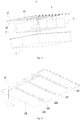
Fig. 1 is a schematic exploded view of a battery module according to an embodiment of the present disclosure; -
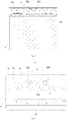
Fig. 2 is a schematic structural view of a monitoring assembly according to an embodiment of the present disclosure; -
Fig. 3 is a schematic structural view of a monitoring assembly according to another embodiment of the present disclosure; -
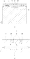
Fig. 4 is a schematic structural view of a monitoring assembly according to still another embodiment of the present disclosure; -
Fig. 5 is a cross-sectional structural view of a battery module according to an embodiment of the present disclosure; -
Fig. 6 is an enlarged view of a portion A inFig. 5 ; -
Fig. 7 is a partial cross-sectional structural view of a battery module according to an embodiment of the present disclosure; -
Fig. 8 is a cross-sectional structural view of a battery module according to another embodiment of the present disclosure; -
Fig. 9 is an enlarged view of a portion B inFig. 8 ; -
Fig. 10 is a schematic exploded view of a battery pack according to an embodiment of the present disclosure; -
Fig. 11 is a schematic exploded view of a battery pack according to another embodiment of the present disclosure; -
Fig. 12 is a schematic view showing a connection state of a cover and a monitoring assembly according to an embodiment of the present disclosure. - In the accompanying drawings, the drawings are not drawn to scale.
-
- 1, battery module;
- 11, secondary battery; 11a, center line; 111, vent;
- 12, monitoring assembly; 121, base plate; 121a, receiving portion; 122, monitoring wire;
- 122a, first segment; 122b, second segment; 122c, intermediate transition segment; 123, insulating layer;
- 13, protective plate;
- 14, isolating plate;
- 2, battery pack;
- 21, case;
- 22, cover;
- 3, battery pack;
- 31, battery unit;
- X, width direction; Y, thickness direction; Z, length direction.
- Below, embodiments of the present disclosure will be further described in detail with reference to the accompanying drawings and embodiments. The detailed description of the embodiments and the accompanying drawings are intended to exemplarily illustrate the principles of the present disclosure and are not intended to limit the scope of the present disclosure. That is, the present disclosure is not limited to the described embodiments.
- In the description of the present disclosure, it should be noted that, unless otherwise stated, the meaning of "a plurality" is two or more; the orientations or positional relationships indicated by the terms "upper", "lower", "left", "right", "inner", "outer" and the like are merely for the purpose of describing the present disclosure and simplifying the description, and are not intended to indicate or imply that the device or component referred to has a particular orientation, is constructed and operated in a particular orientation, and therefore cannot be understood to be a limitation of the present disclosure. Moreover, the terms "first", "second", "third" and the like are used for descriptive purposes only and are not to be construed as indicating or implying relative importance.
- The orientations appearing in the following description are all directions shown in the accompanying drawings and arc not intended to limit the specific configuration of the present disclosure. In the description of the present disclosure, it should be noted that, unless otherwise specified and stated clearly, the terms "install", "connect", and "couple" are to be understood broadly, and may bc, for example, a fixed conncction, a disassemble conncction, or an integral connection, and may be a direct connection or an indirect connection via an intermediate medium. The specific meaning of the above terms in the present disclosure can be understood by the person skilled in the art according to actual circumstance.
- In order to better understand the present disclosure, the embodiments of the present disclosure are described in detail below with reference to
Figs. 1 to 12 . - On one aspect, as shown in
Fig. 1 , abattery module 1 according to an embodiment of the present disclosure includes a plurality ofsecondary batteries 11 and amonitoring assembly 12. The plurality ofsecondary batteries 11 are arranged side by side to form the battery module. Each of thesecondary batteries 11 includes avent 111. When an internal pressure of any of thesecondary batteries 11 exceeds a predetermined pressure, thecorresponding vent 111 may burst to relieve pressure, accompanied by ejection of a high-temperature substance, such as a high-temperature gas or a high-temperature electrolyte. In one example, each of thesecondary batteries 11 is formed as a prismatic cell. Thevent 111 has a circular or racetrack shape. - The monitoring
assembly 12 of the present embodiment is disposed above thesecondary batteries 11. Referring toFigs. 2 to 4 , the monitoringassembly 12 includes abase plate 121 and amonitoring wire 122. Themonitoring wire 122 is coupled to thebase plate 121 such that thebase plate 121 provides a supporting force for themonitoring wire 122, thereby reducing a possibility that themonitoring wire 122 displaces downward and electrically connects with thesecondary batteries 11. Themonitoring wire 122 is disposed corresponding to positions of the respective vents 111. In a normal state, themonitoring wire 122 itself constitutes a complete electrical circuit. When any of thevents 111 bursts, a high temperature or an impact force caused by the bursting can act on themonitoring wire 122, and cause themonitoring wire 122 to be fused or to be cut off by a shear force. As such, themonitoring wire 122 is broken off and a state of thebattery module 1 can be monitored. - The
battery module 1 according to the embodiment of the present disclosure can monitor operating states of thesecondary batteries 11 in real time by providing themonitoring assembly 12. When any of thesecondary batteries 11 bursts, themonitoring wire 122 in themonitoring assembly 12 will be broken off by the high temperature or the relatively large impact force, thereby timely feeding back a signal indicating the bursting of thesecondary battery 11. As such, safety intervention measures can be taken timely to thebattery module 1 to suppress a spread of the high-temperature substance ejected from thesecondary battery 11, and meanwhile, the personnel can be warned and thus use safety of thebattery module 1 can be improved. - In one embodiment, the
battery module 1 further includes a battery management system (BMS) module. Themonitoring wire 122 has two connection ends. The two connection ends are respectively connected to a positive terminal and a negative terminal of the BMS module. In a normal state, themonitoring wire 122 is energized, and thus a current flows through themonitoring wire 122. When themonitoring wire 122 is broken off and gets into an open-circuited state, the current flowing through themonitoring wire 122 is cut off. The BMS module can detect a signal of current change, and after that, the BMS module determines that a bursting of thesecondary battery 11 occurs and automatically takes intervention measures or transmits an alarm signal to the outside. - In one embodiment, there may be 2 to 50
secondary batteries 11. Two or moresecondary batteries 11 are electrically connected in series or in series and parallel. - In one embodiment, the
base plate 121 may be a mica plate, which has a high brittleness and is easily broken when subjected to a large impact force. Thebase plate 121 further may be a plastic plate, which is easily melted under a high temperature and is easily broken when subjected to a large impact force. Thus, when a bursting of thesecondary battery 11 occurs, thebase plate 121 has a small blocking effect on the high-temperature substance, thereby ensuring that more high-temperature substance can act on themonitoring wire 122 and quickly break off themonitoring wire 122. Thebase plate 121 has a predetermined length, a predetermined width, and a predetermined thickness. In each of the embodiments, a width direction X of thebase plate 121 is a direction corresponding to the width, a thickness direction Y of thebase plate 121 is a direction corresponding to the thickness, and a length direction Z of thebase plate 121 is a direction corresponding to the length. Optionally, thebase plate 121 has a thickness of 0.5 mm to 2 mm. - In one embodiment, referring to
Fig. 4 , themonitoring wire 122 includes afirst segment 122a and asecond segment 122b spaced apart from each other in the width direction X. Themonitoring wire 122 further includes anintermediate transition segment 122c that connects thefirst segment 122a and thesecond segment 122b. Thefirst segment 122a and thesecond segment 122b are disposed corresponding to the positions of the respective vents 111. When any of thesecondary batteries 11 bursts, the high-temperature substance may be ejected via thecorresponding vent 111 and act on thefirst segment 122a and/or thesecond segment 122b to break off thefirst segment 122a and/or thesecond segment 122b. Thefirst segment 122a and thesecond segment 122b may be mutually redundant, such that when thefirst segment 122a is not broken off, thesecond segment 122b may be broken off to achieve the monitoring function, or when thesecond segment 122b is not broken off, thefirst segment 122a may be broken off to achieve the monitoring function. According to the invention, a minimum spacing between thefirst segment 122a and thesecond segment 122b is indicated by H (referring toFig. 4 ), and an outer diameter of themonitoring wire 122 is indicated by D (referring toFig. 6 ), wherein H/D ≥ 2.5. The minimum spacing refers to a minimum value among all the values of the spacing between thefirst segment 122a and thesecond segment 122b measured along a straight line in the width direction X. When H/D is less than 2.5, the minimum spacing between thefirst segment 122a and thesecond segment 122b is too small. Thus, in the case where thefirst segment 122a and/or thesecond segment 122b are melted due to the high temperature, it is possible for the molten materials of the meltedfirst segment 122a and/or thesecond segment 122b to flow toward each other and resume an electrical connection of thefirst segment 122a and/or thesecond segment 122b, resulting in that themonitoring wire 122 fails to monitor the bursting of thesecondary battery 11 and that the signal indicating the bursting of thesecondary battery 11 cannot be normally fed back. Further, a too small minimum spacing between thefirst segment 122a and thesecond segment 122b will cause a too short creepage distance between thefirst segment 122a and thesecond segment 122b, thereby causing thefirst segment 122a and thesecond segment 122b easily to be broken down and connected to each other, thereby affecting the normal monitoring. - In one example, the
monitoring wire 122 may be made of aluminum, copper, tin, etc. Themonitoring wire 122 may have a cross section in a circular or polygonal shape. The outer diameter D of themonitoring wire 122 is in a range of 0.1 mm ≤ D ≤ 2 mm. The outer diameter of themonitoring wire 122 refers to a length value of a straight line that passes through a center of themonitoring wire 122 in the cross section of themonitoring wire 122. In the case that the cross section of themonitoring wire 122 is in the circular shape, the outer diameter refers to a diameter of themonitoring wire 122. In the case that the cross section of themonitoring wire 122 is in the polygonal shape, the outer diameter refers to a maximum outer diameter, that is, the length value of the longest straight line passing through the center of the cross section. When the outer diameter of themonitoring wire 122 is less than 0.1 mm, themonitoring wire 122 has a low impact resistance and thus is easily broken off by an external impact force during assembly, which will cause a failure of themonitoring wire 122, and thus a failure of the monitoring of thesecondary batteries 11. When the outer diameter of themonitoring wire 122 is greater than 2 mm, themonitoring wire 122 has a too high resistance to high temperature and a too high impact resistance, to be broken off by the high-temperature substance or by the external impact force, which will reduce a monitoring sensitivity and result in that the monitoring of thesecondary batteries 11 cannot be realized by the way of opening-circuit themonitoring wire 122. Meanwhile, if the outer diameter of themonitoring wire 122 is greater than 2 mm, more installation space may be occupied, which will reduce an energy density of thebattery module 1. The minimum spacing H between thefirst segment 122a and thesecond segment 122b is in a range of 5 mm ≤ H ≤ 50 mm. When the minimum spacing H is less than 5 mm, the minimum spacing between thefirst segment 122a and thesecond segment 122b is too small. Thus, in the case where thefirst segment 122a and/or thesecond segment 122b are melted under the high temperature, it is possible for the molten materials of the meltedfirst segment 122a and/or thesecond segment 122b to flow toward each other and resume the electrical connection of thefirst segment 122a and/or thesecond segment 122b, which in turn will cause a failure of the monitoring function. Further, a too small minimum spacing between thefirst segment 122a and thesecond segment 122b will cause a too short creepage distance between thefirst segment 122a and thesecond segment 122b, thereby causing thefirst segment 122a and thesecond segment 122b easily to be broken down and connected to each other, and thus affecting the normal monitoring of themonitoring wire 122. When the minimum spacing H is greater than 50 mm, the spacing between thefirst segment 122a and thesecond segment 122b is too large, and thus thefirst segment 122a and thesecond segment 122b arc relatively far from centers of thevents 111. Therefore, the impact force directly acted on thefirst segment 122a and thesecond segment 122b by the high-temperature substance may be reduced, and the high-temperature substance may be cooled due to a long displacement distance and thus act on thefirst segment 122a and thesecond segment 122b with a lower temperature. As a result, it might be difficult for thefirst segment 122a and thesecond segment 122b to be fused by the high-temperature substance or to be cut off by the external impact force, thereby causing a failure of themonitoring wire 122 and thus a failure of the monitoring of thesecondary batteries 11 by means of the open-circuit of themonitoring wire 122. - In one embodiment, referring to
Fig. 1 , thevent 111 has acenter line 11a extending in the length direction Z of thebase plate 121. Thefirst segment 122a and thesecond segment 122b are respectively disposed on two sides of thecenter line 11a. Optionally, thefirst segment 122a and thesecond segment 122b of themonitoring wire 122 extend in the length direction Z. In one example, themonitoring wire 122 has a U-shaped configuration. By measuring along a straight line in the width direction X, the spacing values measured at the various positions between thefirst segment 122a and thesecond segment 122b are equal. In one example, thefirst segment 122a and thesecond segment 122b are identical in configuration, and are disposed in parallel. In another example, thefirst segment 122a and thesecond segment 122b are inclined toward a direction away from each other, such that the spacing between them gradually decreases or increases in the length direction Z. - In one embodiment, there may be two or
more monitoring wires 122. The two ormore monitoring wires 122 are arranged side by side in one direction, and are all disposed corresponding to the positions of thevents 111. The two ormore monitoring wires 122 are manually redundant. When any of thesecondary batteries 11 bursts, any of the two ormore monitoring wires 122 can monitor the state of thesecondary battery 11, thereby improving a monitoring accuracy. When any of the two ormore monitoring wires 122 fails to monitor or fails to operate normally, the remainingmonitoring wires 122 can normally complete the monitoring operation, thereby reducing a possibility of missing detection. - In one embodiment, referring to
Fig. 2 , themonitoring wire 122 is disposed directly on a surface of thebase plate 121. Surfaces of thebase plate 121 and themonitoring wire 122 coupled to each other arc flat. Thebase plate 121 and themonitoring wire 122 arc fixedly coupled in a snap fit manner or in a bonding manner. In another embodiment, as shown inFig. 3 , thebase plate 121 is provided with a receivingportion 121a. Themonitoring wire 122 is disposed in the receivingportion 121a. Themonitoring wire 122 has an overall shape matching with a shape of the receivingportion 121a. When themonitoring wire 122 has a U-shaped configuration, the receivingportion 121a also has a U-shaped configuration. The receivingportion 121a is disposed corresponding to the positions of thevents 111. By receiving themonitoring wire 122 in the receivingportion 121a, on the one hand, it is conducive to improving a structural compactness, saving space, and improving the energy density of thebattery module 1, and on the other hand, themonitoring wire 122 is restrained by the base plate, which can improve a positional stability of themonitoring wire 122, reduce a possibility that themonitoring wire 122 is displaced and cannot maintain to correspond to the positions of thevents 111, and reduce a possibility that the high-temperature substance cannot act on the displacedmonitoring wire 122, thereby causing the monitoring failure. - In one embodiment, as shown in
Figs. 5 and 6 , the receivingportion 121a penetrates thebase plate 121 in the thickness direction Y of thebase plate 121. The receivingportion 121a extends in the length direction Z. Themonitoring wire 122 is disposed directly corresponding to thevents 111 of thesecondary batteries 11. When any of thesecondary batteries 11 bursts, the internal high-temperature substance can directly act on themonitoring wire 122, and themonitoring wire 122 can be quickly fused or cut off by the external impact force, thereby breaking off themonitoring wire 122, which is conducive to shortening monitoring time. A maximum dimension of themonitoring wire 122 in the thickness direction Y is smaller than the thickness of thebase plate 121, and themonitoring wire 122 is disposed in the receivingportion 121a. In the thickness direction Y, themonitoring wire 122 is not protruded out of thebase plate 121, and thus can be protected by thebase plate 121, thereby reducing a possibility that themonitoring wire 122 is accidentally broken off by an external force during assembly or later use. Further, themonitoring wire 122 does not occupy more installation space in the thickness direction Y, which can improve an overall structural compactness of themonitoring assembly 12, thereby improving the energy density of thebattery module 1. - In another embodiment, referring to
Fig. 7 , the receivingportion 121a is formed as a groove recessed in the thickness direction Y of thebase plate 121. The groove has a bottom wall without penetrating thebase plate 121. Thebase plate 121 can provide a supporting force for themonitoring wire 122 in the thickness direction Y. When vibration occurs during use of thebattery module 1, it is not easy for themonitoring wire 122 to disengage from the groove. In the present embodiment, thebase plate 121 itself may be melted under high temperature or may be broken by an impact force. In one example, the groove extends along a straight line in the length direction Z to form a strip-like groove. Themonitoring wire 122 is also formed in a strip-like configuration entirely, which matches with the shape of the groove. - In one embodiment, referring to
Figs. 8 and 9 , the monitoringassembly 12 further includes an insulatinglayer 123 that encloses themonitoring wire 122. The insulatinglayer 123 is filled in the receivingportion 121a. Themonitor wire 122 is coupled to thebase plate 121 via the insulatinglayer 123. When any of thevents 111 bursts, the insulatinglayer 123 can be melted or broken. The insulatinglayer 123 can insulate themonitoring wire 122 from adjacent energized components, and prevent a short circuit caused by contact between themonitoring wire 122 and the adjacent energized components. The insulatinglayer 123 can fill a gap between themonitor wire 122 and thebase plate 121, thereby improving the positional stability of themonitor wire 122. The insulatinglayer 123 can reduce a possibility of a breakdown and short circuit of thefirst segment 122a and thesecond segment 122b. When any of thesecondary batteries 11 bursts, the high-temperature substance can first melt or break the insulatinglayer 123 to expose theinternal monitoring wire 122, and then the high-temperature substance fuses or cut off themonitoring wire 122. - In one embodiment, a thickness of the insulating
layer 123 is indicated by M, and a maximum outer diameter of themonitoring wire 122 is indicated by D, wherein 0.05 ≤ M/D ≤ 10. When the M/D is less than 0.05, the insulatinglayer 123 is too thin, resulting in that the insulating property thereof may be deteriorated, and a possibility of occurrence of insulation failure may be increased. When the M/D is greater than 10, the insulatinglayer 123 is too thick, resulting in that when any of thevents 111 bursts, the high-temperature substance is easily blocked by the insulatinglayer 123, and it is difficult to quickly melt or break the insulatinglayer 123, thereby prolonging the monitoring time required by themonitoring wire 122. In one example, the thickness value measured at any position of the insulatinglayer 123 is M. In another example, in the thickness direction Y, a thickness of a portion of the insulatinglayer 123 disposed below themonitoring wire 122 is M. The thickness value M of the portion of the insulatinglayer 123 disposed below themonitoring wire 122 is obtained by measuring along a straight line in the thickness direction Y. - In one embodiment, the thickness of the insulating
layer 123 is indicated by M, wherein 0.1 mm ≤ M ≤ 1 mm. The insulatinglayer 123 may be made of a polymer material, such as polyethylene, polypropylene or polyester, or may be made of ceramic or mica. The insulatinglayer 123 has an insulating property greater than 500 MΩ. When the thickness of the insulatinglayer 123 is less than 0.1 mm, the insulation performance of the insulatinglayer 123 is low, which may increase a possibility that thefirst segment 122a and thesecond segment 122b are broken down and short-circuited. As a result, an error alarm may be sent out, and the monitoring accuracy may be reduced. When the thickness of the insulatinglayer 123 is greater than 1 mm, it is more difficult to melt or break the insulatinglayer 123, resulting in that when any of thesecondary batteries 11 occurs, the insulatinglayer 123 fails to be melted or broken to expose themonitoring wire 122. As a result, thefirst segment 122a and thesecond segment 122b cannot be open-circuited, the monitoring wire cannot complete the monitoring operation normally, and the bursting of thesecondary battery 11 cannot be detected. - In one embodiment, referring to
Fig. 6 orFig. 7 , the monitoringassembly 12 further includes aprotective plate 13. Theprotective plate 13 is disposed on a side of thebase plate 121 close to thesecondary battery 11 in the thickness direction Y of thebase plate 121. Theprotective plate 13 can provide additional protection. When any of thesecondary batteries 11 bursts, theprotective plate 13 can prevent an outward diffusion of the high-temperature substance and improve the safety of thebattery module 1. Theprotective plate 13 may be fixedly coupled to thebase plate 121, and thebase plate 121 and theprotective plate 13 are stacked in the thickness direction Y. Optionally, theprotective plate 13 is made of a high temperature resistant and high strength insulating material, such as mica, ceramic, and a composite material. Optionally, thebase plate 121 and theprotective plate 13 are bonded by a high temperature resistant adhesive, such as silicone adhesive, high temperature epoxy adhesive, organosilicon, or phcnolic. - In one embodiment, referring to
Fig. 6 orFig. 7 , the monitoringassembly 12 further includes an isolatingplate 14. The isolatingplate 14 is disposed on a side of thebase plate 121 away from thesecondary batteries 11 in the thickness direction Y of thebase plate 121. The isolatingplate 14 isolates thesecondary batteries 11 from the monitoringassembly 12. The isolatingplate 14 may be fixedly coupled to thebase plate 121, and thebase plate 121 and the isolatingplate 14 are stacked in the thickness direction Y. When a bursting of any of thesecondary batteries 11 occurs, the high-temperature substance first melts or breaks the isolatingplate 14, and then fuses or cuts off themonitoring wire 122. Optionally, the isolatingplate 14 is made of an insulating material such as mica or plastic. Optionally, thebase plate 121 and the isolatingplate 14 are bonded by a high temperature resistant adhesive, such as silicone adhesive, high temperature epoxy adhesive, organosilicon, or phenolic. - The
battery module 1 according to the embodiments of the present disclosure can monitor the states of thesecondary batteries 11 in real time by providing themonitoring assembly 12. The monitoringassembly 12 includes thebase plate 121 and themonitoring wire 122, and themonitoring wire 122 itself constitutes a complete circuit. When any of thesecondary batteries 11 bursts and the high-temperature substance is ejected, themonitoring wire 122 included in themonitoring assembly 12 is fused or cut off and thus is broken off. In this case, themonitoring wire 122 cannot transmit an electrical signal any more, and a signal indicating the bursting of thesecondary battery 11 can be timely fed back, which facilitates to timely take safety intervention measures to thebattery module 1 and timely suppress the spread of the high-temperature substance ejected from thesecondary battery 11, thereby improving the use safety of thebattery module 1. - Referring to
Fig. 10 , according to an embodiment of the present disclosure, abattery pack 2 includes thebattery module 1 according to any of the above embodiments. In one embodiment, thebattery pack 2 includes two ormore battery modules 1. Themonitoring wires 122 included in the two ormore battery modules 1 are connected in series. After all themonitoring wires 122 are connected in series, a main input terminal and a main output terminal are respectively connected to the positive terminal and the negative terminal of the battery management system module, and thus all thebattery modules 1 are monitored in real time. - The
battery pack 2 according to the embodiment of the present disclosure can monitor the states of thebattery modules 1 in real time by the monitoringassembly 12. When any of thesecondary batteries 11 bursts and a high-temperature substance is ejected, themonitoring wire 122 included in themonitoring assembly 12 is fused or cut off and thus is broken off. In this case, themonitoring wire 122 cannot transmit an electrical signal any more, and a signal indicating the bursting of thesecondary battery 11 can be timely fed back, which facilitates to timely take safety intervention measures to thebattery pack 2 and timely suppress the spread of the high-temperature substance ejected from thebattery module 1, thereby improving the use safety of thebattery pack 2. - In one embodiment, the
battery pack 2 further includes acase 21 and acover 22. Thecase 21 has an accommodating chamber for accommodating thebattery module 1. After thebattery module 1 is placed in the accommodating chamber of thecase 21, thecase 21 and thecover 22 are fixedly coupled to each other. - In one embodiment, referring to
Fig. 11 and Fig. 12 , an embodiment of the present disclosure further discloses abattery pack 3 including abattery unit 31, acover 22, and amonitoring assembly 12. Thecover 22 is disposed above thebattery unit 31. The monitoringassembly 12 is disposed on thecover 22. The monitoringassembly 12 includes abase plate 121 and amonitoring wire 122. Themonitoring wire 122 is coupled to thebase plate 121. When a bursting of thebattery unit 31 occurs, themonitoring wire 122 can be broken off to achieve monitoring of a state of thebattery unit 31. - In one embodiment, the
battery unit 31 may be a singlesecondary battery 11, thebattery module 1 according to any of the above embodiments, or a battery module of the prior art. - In one embodiment, the
base plate 121 of themonitoring assembly 12 is adhesively coupled to thecover 22. Optionally, thebase plate 121 and thecover 22 are bonded by a high temperature resistant adhesive, such as silicone adhesive, high temperature epoxy adhesive, organosilicon, or phenolic. - In one embodiment, the
battery pack 3 further includes acase 21. Thecase 21 has an accommodating chamber for accommodating thebattery unit 31. After thebattery unit 31 is placed in the accommodating chamber of thecase 21, thecase 21 and thecover 22 are fixedly coupled to each other. - The
battery pack 3 according to the embodiment of the present disclosure can monitor the state of thebattery unit 31 in real time by providing themonitoring assembly 12. The monitoringassembly 12 includes thebase plate 121 and themonitoring wire 122. In a normal state, themonitoring wire 122 itself constitutes a complete circuit. When thebattery unit 31 bursts and the high-temperature substance is ejected from thebattery unit 31, themonitoring wire 122 included in themonitoring assembly 12 is fused or cut off and thus is broken off. In this case, themonitoring wire 122 cannot transmit an electrical signal any more, and a signal indicating the bursting of thebattery unit 31 can be timely fed back, which facilitates to timely take safety intervention measures to thebattery pack 3 and timely suppress the spread of the high-temperature substance ejected from thebattery unit 31, thereby improving the use safety of thebattery pack 3. - The present invention is not limited to the specific embodiments disclosed herein, but includes all technical solutions falling within the scope of the claims.
Claims (13)
- A battery module (1), comprising:a plurality of secondary batteries (11) arranged side by side, each of which comprises a vent (111);a monitoring assembly (12), disposed above the plurality of secondary batteries (11) and comprising a base plate (121) and a monitoring wire (122), wherein the monitoring wire (122) is coupled to the base plate (121); the monitoring wire (122) is disposed corresponding to positions of the vents (111) of the plurality of secondary batteries (11), and can be broken off when any of the vents (111) bursts, so as to monitor a state of the battery module (1),characterized in that,the monitoring wire (122) comprises a first segment (122a) and a second segment (122b) spaced apart from each other in a width direction (X) of the base plate (121), the vent (111) of each of the plurality of secondary batteries (11) has a center line (11a) extending in a length direction (Z) of the base plate (121), and the first segment (122a) and the second segment (122b) are respectively disposed on two sides of the center line (11a), anda minimum spacing between the first segment (122a) and the second segment (122b) is indicated by H, and an outer diameter of the monitoring wire (122) is indicated by D, wherein H/D ≥ 2.5.
- The battery module (1) according to claim 1, characterized in that, the monitoring wire (122) has a U-shaped configuration.
- The battery module (1) according to claim 1 or claim 2, characterized in that, the outer diameter D of the monitoring wire (122) is in a range of 0.1 mm ≤ D ≤ 2 mm, and the minimum spacing H between the first segment (122a) and the second segment (122b) is in a range of 5 mm ≤ H ≤ 50 mm.
- The battery module (1) according to any of claims 1-3, characterized in that, the base plate (121) is provided with a receiving portion (121a), in which the monitoring wire (122) is disposed, and the monitoring wire (122) has a shape matching with a shape of the receiving portion (121a).
- The battery module (1) according to claim 4, characterized in that, the receiving portion (121a) is formed as a groove recessed in a thickness direction of the base plate (121), and the groove has a bottom wall without penetrating the base plate (121); or,
the receiving portion (121a) is configured to penetrate the base plate (121) in a thickness direction (Y) of the base plate (121), wherein a maximum dimension of the monitoring wire (122) in the thickness direction (Y) of the base plate (121) is smaller than a thickness of the base plate (121), and the monitoring wire (122) is disposed in the receiving portion (121a). - The battery module (1) according to claim 4 or claim 5, characterized in that, the monitoring assembly (12) further comprises an insulating layer (123) enclosing the monitoring wire (122), and the insulating layer (123) is filled in the receiving portion (121a), wherein the monitoring wire (122) is coupled to the base plate (121) via the insulating layer (123).
- The battery module (1) according to claim 6, characterized in that, the insulating layer (123) has a thickness indicated by M, and a maximum outer diameter of the monitoring wire (122) is indicated by D, wherein 0.05 ≤ M/D ≤ 10.
- The battery module (1) according to claim 7, characterized in that, a portion of the insulating layer (123) disposed below the monitoring wire (122) has a thickness in the thickness direction (Y) equal to M.
- The battery module (1) according to claim 7 or claim 8, characterized in that, the thickness M of the insulating layer (123) is in a range of 0.1 mm ≤ M ≤ 1 mm.
- The battery module (1) according to any of claims 1-9, characterized in that, the monitoring assembly (12) further comprises:a protective plate (13), which is disposed on a side of the base plate (121) close to the plurality of secondary batteries (11) in a thickness direction (Y) of the base plate (121); and/oran isolating plate (14), which is disposed on a side of the base plate (121) away from the plurality of secondary batteries (11) in a thickness direction (Y) of the base plate (121).
- A battery pack (2), characterized in that, comprising a battery module (1) according to any of claims 1 to 10.
- The battery pack (2) according to claim 11, characterized in that, there are two or more battery modules (1), and the monitoring wires (122) included in the two or more battery modules (1) are connected in series.
- A battery pack (3), comprising:a battery unit (31);a cover (22), disposed above the battery unit (31); anda monitoring assembly (12), which is disposed on the cover (22) and comprises a base plate (121) and a monitoring wire (122), wherein the monitoring wire (122) is coupled to the base plate (121), and when the battery unit (31) bursts, the monitoring wire (122) can be broken off to monitor a state of the battery unit (31),characterized in that,the monitoring wire (122) comprises a first segment (122a) and a second segment (122b) spaced apart from each other in a width direction (X) of the base plate (121), the vent (111) of each of the plurality of secondary batteries (11) has a center line (11a) extending in a length direction (Z) of the base plate (121), and the first segment (122a) and the second segment (122b) are respectively disposed on two sides of the center line (11a), anda minimum spacing between the first segment (122a) and the second segment (122b) is indicated by H, and an outer diameter of the monitoring wire (122) is indicated by D, wherein H/D ≥ 2.5.
Applications Claiming Priority (1)
| Application Number | Priority Date | Filing Date | Title |
|---|---|---|---|
| CN201910359968.6A CN111864292B (en) | 2019-04-30 | 2019-04-30 | Battery modules and battery packs |
Publications (2)
| Publication Number | Publication Date |
|---|---|
| EP3734747A1 EP3734747A1 (en) | 2020-11-04 |
| EP3734747B1 true EP3734747B1 (en) | 2021-08-25 |
Family
ID=68762367
Family Applications (1)
| Application Number | Title | Priority Date | Filing Date |
|---|---|---|---|
| EP19210175.6A Active EP3734747B1 (en) | 2019-04-30 | 2019-11-19 | Battery module and battery pack |
Country Status (4)
| Country | Link |
|---|---|
| US (1) | US11211667B2 (en) |
| EP (1) | EP3734747B1 (en) |
| CN (1) | CN111864292B (en) |
| WO (1) | WO2020220887A1 (en) |
Families Citing this family (4)
| Publication number | Priority date | Publication date | Assignee | Title |
|---|---|---|---|---|
| CN209822756U (en) * | 2019-04-30 | 2019-12-20 | 宁德时代新能源科技股份有限公司 | Battery module and battery pack |
| CN110967643B (en) * | 2019-04-30 | 2021-01-22 | 宁德时代新能源科技股份有限公司 | Thermal runaway detection circuit and method |
| CN112332032B (en) | 2020-06-23 | 2024-02-23 | 宁德时代新能源科技股份有限公司 | Battery pack and device using battery pack as power supply |
| CN219203254U (en) * | 2022-10-21 | 2023-06-16 | 杭州高特电子设备股份有限公司 | A battery that detects the opening of the battery safety valve |
Family Cites Families (18)
| Publication number | Priority date | Publication date | Assignee | Title |
|---|---|---|---|---|
| JP4216898B1 (en) * | 2008-03-28 | 2009-01-28 | 和征 榊原 | Battery pack |
| WO2012157094A1 (en) | 2011-05-18 | 2012-11-22 | 日立ビークルエナジー株式会社 | Electricity storage device |
| CN205564914U (en) * | 2016-04-26 | 2016-09-07 | 华霆(合肥)动力技术有限公司 | Detection apparatus for battery module explodes state of spouting |
| CN105762432B (en) * | 2016-04-26 | 2018-08-24 | 华霆(合肥)动力技术有限公司 | A kind of detection method and device of the quick-fried spray state of battery modules |
| KR102096983B1 (en) * | 2017-09-08 | 2020-04-03 | 주식회사 엘지화학 | Battery module with a structure to break a connector using venting gas |
| CN207800817U (en) * | 2018-01-17 | 2018-08-31 | 华霆(合肥)动力技术有限公司 | Cell safety monitoring device and battery modules |
| CN108995534A (en) * | 2018-01-31 | 2018-12-14 | 太原科技大学 | A kind of anti-explosion electric sweeper malfunction monitoring alarm system |
| CN207938748U (en) * | 2018-04-10 | 2018-10-02 | 华霆(合肥)动力技术有限公司 | Battery unsteady repression mechanism and system |
| CN108565515B (en) | 2018-04-10 | 2023-11-21 | 华霆(合肥)动力技术有限公司 | Battery instability suppression mechanism and system |
| CN108682756A (en) | 2018-05-21 | 2018-10-19 | 安徽江淮汽车集团股份有限公司 | Battery modules side plate and battery modules |
| CN108767343B (en) * | 2018-07-11 | 2023-11-21 | 华霆(合肥)动力技术有限公司 | Battery detection assembly, battery module and manufacturing method |
| CN208538928U (en) | 2018-08-10 | 2019-02-22 | 浙江吉利汽车研究院有限公司 | A battery module capable of preventing thermal runaway diffusion |
| CN109103529B (en) * | 2018-08-27 | 2020-05-26 | 华霆(合肥)动力技术有限公司 | Detection structure and power supply device |
| CN109728374A (en) | 2018-12-29 | 2019-05-07 | 华霆(合肥)动力技术有限公司 | Battery thermal management monitoring device and electric car |
| CN209730085U (en) | 2019-04-30 | 2019-12-03 | 宁德时代新能源科技股份有限公司 | Battery modules |
| CN209730091U (en) * | 2019-04-30 | 2019-12-03 | 宁德时代新能源科技股份有限公司 | Battery modules and battery packs |
| CN209822756U (en) | 2019-04-30 | 2019-12-20 | 宁德时代新能源科技股份有限公司 | Battery module and battery pack |
| CN209860056U (en) | 2019-04-30 | 2019-12-27 | 宁德时代新能源科技股份有限公司 | Battery modules and battery packs |
-
2019
- 2019-04-30 CN CN201910359968.6A patent/CN111864292B/en active Active
- 2019-11-15 US US16/684,595 patent/US11211667B2/en active Active
- 2019-11-19 EP EP19210175.6A patent/EP3734747B1/en active Active
-
2020
- 2020-03-27 WO PCT/CN2020/081769 patent/WO2020220887A1/en not_active Ceased
Also Published As
| Publication number | Publication date |
|---|---|
| CN111864292A (en) | 2020-10-30 |
| EP3734747A1 (en) | 2020-11-04 |
| US11211667B2 (en) | 2021-12-28 |
| CN111864292B (en) | 2025-03-11 |
| US20200350536A1 (en) | 2020-11-05 |
| WO2020220887A1 (en) | 2020-11-05 |
Similar Documents
| Publication | Publication Date | Title |
|---|---|---|
| EP3734747B1 (en) | Battery module and battery pack | |
| EP3761397B1 (en) | Battery module and battery pack | |
| EP3920306B1 (en) | Battery module | |
| US10050315B2 (en) | Battery module with fusible conductors | |
| US11489230B2 (en) | Battery module and battery pack | |
| CN209804781U (en) | Battery module and have its vehicle | |
| EP3796416B1 (en) | Battery pack | |
| US20250337125A1 (en) | Power Battery System for a Vehicle and Thermal Assessment Method | |
| KR102804168B1 (en) | Battery, electrical device, method for manufacturing battery and manufacturing device | |
| CN209730091U (en) | Battery modules and battery packs | |
| KR20110109806A (en) | Protection circuit module for secondary battery pack and secondary battery pack | |
| KR20160113888A (en) | Battery pack | |
| WO2015033560A1 (en) | Battery circuit and protection circuit | |
| CN217641704U (en) | A battery pack with both active and passive arc extinguishing functions | |
| KR20130123981A (en) | Battery pack system with integration mount fuse apparatus for circuit breaking over-current in sensing assembly structure | |
| JP3111276B2 (en) | Secondary battery explosion prevention device | |
| KR20070075927A (en) | Small battery pack with improved safety | |
| CN213023492U (en) | Thermal runaway detection device for battery pack | |
| KR20220141594A (en) | Sensing wire short preventing device using PCB pattern | |
| KR20260047861A (en) | Busbar assembly and battery pack including the same | |
| CN121662824A (en) | A lithium battery cell with internal short-circuit self-breaking protection | |
| KR20250059892A (en) | Busbar assembly and battery pack including the same | |
| JP2023551995A (en) | Battery module with pressure sensor for thermal runaway detection | |
| CN120581844A (en) | Tab components, battery cells and battery structures |
Legal Events
| Date | Code | Title | Description |
|---|---|---|---|
| PUAI | Public reference made under article 153(3) epc to a published international application that has entered the european phase |
Free format text: ORIGINAL CODE: 0009012 |
|
| STAA | Information on the status of an ep patent application or granted ep patent |
Free format text: STATUS: THE APPLICATION HAS BEEN PUBLISHED |
|
| AK | Designated contracting states |
Kind code of ref document: A1 Designated state(s): AL AT BE BG CH CY CZ DE DK EE ES FI FR GB GR HR HU IE IS IT LI LT LU LV MC MK MT NL NO PL PT RO RS SE SI SK SM TR |
|
| AX | Request for extension of the european patent |
Extension state: BA ME |
|
| STAA | Information on the status of an ep patent application or granted ep patent |
Free format text: STATUS: REQUEST FOR EXAMINATION WAS MADE |
|
| 17P | Request for examination filed |
Effective date: 20210204 |
|
| RBV | Designated contracting states (corrected) |
Designated state(s): AL AT BE BG CH CY CZ DE DK EE ES FI FR GB GR HR HU IE IS IT LI LT LU LV MC MK MT NL NO PL PT RO RS SE SI SK SM TR |
|
| GRAP | Despatch of communication of intention to grant a patent |
Free format text: ORIGINAL CODE: EPIDOSNIGR1 |
|
| STAA | Information on the status of an ep patent application or granted ep patent |
Free format text: STATUS: GRANT OF PATENT IS INTENDED |
|
| RIC1 | Information provided on ipc code assigned before grant |
Ipc: H01M 50/20 20210101ALI20210504BHEP Ipc: H01M 10/48 20060101AFI20210504BHEP |
|
| INTG | Intention to grant announced |
Effective date: 20210520 |
|
| GRAS | Grant fee paid |
Free format text: ORIGINAL CODE: EPIDOSNIGR3 |
|
| GRAA | (expected) grant |
Free format text: ORIGINAL CODE: 0009210 |
|
| STAA | Information on the status of an ep patent application or granted ep patent |
Free format text: STATUS: THE PATENT HAS BEEN GRANTED |
|
| AK | Designated contracting states |
Kind code of ref document: B1 Designated state(s): AL AT BE BG CH CY CZ DE DK EE ES FI FR GB GR HR HU IE IS IT LI LT LU LV MC MK MT NL NO PL PT RO RS SE SI SK SM TR |
|
| REG | Reference to a national code |
Ref country code: CH Ref legal event code: EP |
|
| REG | Reference to a national code |
Ref country code: DE Ref legal event code: R096 Ref document number: 602019007162 Country of ref document: DE |
|
| REG | Reference to a national code |
Ref country code: IE Ref legal event code: FG4D Ref country code: AT Ref legal event code: REF Ref document number: 1424729 Country of ref document: AT Kind code of ref document: T Effective date: 20210915 |
|
| REG | Reference to a national code |
Ref country code: LT Ref legal event code: MG9D |
|
| REG | Reference to a national code |
Ref country code: NL Ref legal event code: MP Effective date: 20210825 |
|
| REG | Reference to a national code |
Ref country code: AT Ref legal event code: MK05 Ref document number: 1424729 Country of ref document: AT Kind code of ref document: T Effective date: 20210825 |
|
| PG25 | Lapsed in a contracting state [announced via postgrant information from national office to epo] |
Ref country code: LT Free format text: LAPSE BECAUSE OF FAILURE TO SUBMIT A TRANSLATION OF THE DESCRIPTION OR TO PAY THE FEE WITHIN THE PRESCRIBED TIME-LIMIT Effective date: 20210825 Ref country code: BG Free format text: LAPSE BECAUSE OF FAILURE TO SUBMIT A TRANSLATION OF THE DESCRIPTION OR TO PAY THE FEE WITHIN THE PRESCRIBED TIME-LIMIT Effective date: 20211125 Ref country code: AT Free format text: LAPSE BECAUSE OF FAILURE TO SUBMIT A TRANSLATION OF THE DESCRIPTION OR TO PAY THE FEE WITHIN THE PRESCRIBED TIME-LIMIT Effective date: 20210825 Ref country code: NO Free format text: LAPSE BECAUSE OF FAILURE TO SUBMIT A TRANSLATION OF THE DESCRIPTION OR TO PAY THE FEE WITHIN THE PRESCRIBED TIME-LIMIT Effective date: 20211125 Ref country code: PT Free format text: LAPSE BECAUSE OF FAILURE TO SUBMIT A TRANSLATION OF THE DESCRIPTION OR TO PAY THE FEE WITHIN THE PRESCRIBED TIME-LIMIT Effective date: 20211227 Ref country code: HR Free format text: LAPSE BECAUSE OF FAILURE TO SUBMIT A TRANSLATION OF THE DESCRIPTION OR TO PAY THE FEE WITHIN THE PRESCRIBED TIME-LIMIT Effective date: 20210825 Ref country code: FI Free format text: LAPSE BECAUSE OF FAILURE TO SUBMIT A TRANSLATION OF THE DESCRIPTION OR TO PAY THE FEE WITHIN THE PRESCRIBED TIME-LIMIT Effective date: 20210825 Ref country code: RS Free format text: LAPSE BECAUSE OF FAILURE TO SUBMIT A TRANSLATION OF THE DESCRIPTION OR TO PAY THE FEE WITHIN THE PRESCRIBED TIME-LIMIT Effective date: 20210825 Ref country code: SE Free format text: LAPSE BECAUSE OF FAILURE TO SUBMIT A TRANSLATION OF THE DESCRIPTION OR TO PAY THE FEE WITHIN THE PRESCRIBED TIME-LIMIT Effective date: 20210825 Ref country code: ES Free format text: LAPSE BECAUSE OF FAILURE TO SUBMIT A TRANSLATION OF THE DESCRIPTION OR TO PAY THE FEE WITHIN THE PRESCRIBED TIME-LIMIT Effective date: 20210825 |
|
| PG25 | Lapsed in a contracting state [announced via postgrant information from national office to epo] |
Ref country code: PL Free format text: LAPSE BECAUSE OF FAILURE TO SUBMIT A TRANSLATION OF THE DESCRIPTION OR TO PAY THE FEE WITHIN THE PRESCRIBED TIME-LIMIT Effective date: 20210825 Ref country code: LV Free format text: LAPSE BECAUSE OF FAILURE TO SUBMIT A TRANSLATION OF THE DESCRIPTION OR TO PAY THE FEE WITHIN THE PRESCRIBED TIME-LIMIT Effective date: 20210825 Ref country code: GR Free format text: LAPSE BECAUSE OF FAILURE TO SUBMIT A TRANSLATION OF THE DESCRIPTION OR TO PAY THE FEE WITHIN THE PRESCRIBED TIME-LIMIT Effective date: 20211126 |
|
| PG25 | Lapsed in a contracting state [announced via postgrant information from national office to epo] |
Ref country code: NL Free format text: LAPSE BECAUSE OF FAILURE TO SUBMIT A TRANSLATION OF THE DESCRIPTION OR TO PAY THE FEE WITHIN THE PRESCRIBED TIME-LIMIT Effective date: 20210825 |
|
| PG25 | Lapsed in a contracting state [announced via postgrant information from national office to epo] |
Ref country code: DK Free format text: LAPSE BECAUSE OF FAILURE TO SUBMIT A TRANSLATION OF THE DESCRIPTION OR TO PAY THE FEE WITHIN THE PRESCRIBED TIME-LIMIT Effective date: 20210825 |
|
| REG | Reference to a national code |
Ref country code: DE Ref legal event code: R097 Ref document number: 602019007162 Country of ref document: DE |
|
| PG25 | Lapsed in a contracting state [announced via postgrant information from national office to epo] |
Ref country code: SM Free format text: LAPSE BECAUSE OF FAILURE TO SUBMIT A TRANSLATION OF THE DESCRIPTION OR TO PAY THE FEE WITHIN THE PRESCRIBED TIME-LIMIT Effective date: 20210825 Ref country code: SK Free format text: LAPSE BECAUSE OF FAILURE TO SUBMIT A TRANSLATION OF THE DESCRIPTION OR TO PAY THE FEE WITHIN THE PRESCRIBED TIME-LIMIT Effective date: 20210825 Ref country code: RO Free format text: LAPSE BECAUSE OF FAILURE TO SUBMIT A TRANSLATION OF THE DESCRIPTION OR TO PAY THE FEE WITHIN THE PRESCRIBED TIME-LIMIT Effective date: 20210825 Ref country code: EE Free format text: LAPSE BECAUSE OF FAILURE TO SUBMIT A TRANSLATION OF THE DESCRIPTION OR TO PAY THE FEE WITHIN THE PRESCRIBED TIME-LIMIT Effective date: 20210825 Ref country code: CZ Free format text: LAPSE BECAUSE OF FAILURE TO SUBMIT A TRANSLATION OF THE DESCRIPTION OR TO PAY THE FEE WITHIN THE PRESCRIBED TIME-LIMIT Effective date: 20210825 Ref country code: AL Free format text: LAPSE BECAUSE OF FAILURE TO SUBMIT A TRANSLATION OF THE DESCRIPTION OR TO PAY THE FEE WITHIN THE PRESCRIBED TIME-LIMIT Effective date: 20210825 |
|
| PG25 | Lapsed in a contracting state [announced via postgrant information from national office to epo] |
Ref country code: MC Free format text: LAPSE BECAUSE OF FAILURE TO SUBMIT A TRANSLATION OF THE DESCRIPTION OR TO PAY THE FEE WITHIN THE PRESCRIBED TIME-LIMIT Effective date: 20210825 |
|
| PLBE | No opposition filed within time limit |
Free format text: ORIGINAL CODE: 0009261 |
|
| STAA | Information on the status of an ep patent application or granted ep patent |
Free format text: STATUS: NO OPPOSITION FILED WITHIN TIME LIMIT |
|
| PG25 | Lapsed in a contracting state [announced via postgrant information from national office to epo] |
Ref country code: LU Free format text: LAPSE BECAUSE OF NON-PAYMENT OF DUE FEES Effective date: 20211119 Ref country code: IT Free format text: LAPSE BECAUSE OF FAILURE TO SUBMIT A TRANSLATION OF THE DESCRIPTION OR TO PAY THE FEE WITHIN THE PRESCRIBED TIME-LIMIT Effective date: 20210825 Ref country code: BE Free format text: LAPSE BECAUSE OF NON-PAYMENT OF DUE FEES Effective date: 20211130 |
|
| REG | Reference to a national code |
Ref country code: BE Ref legal event code: MM Effective date: 20211130 |
|
| 26N | No opposition filed |
Effective date: 20220527 |
|
| PG25 | Lapsed in a contracting state [announced via postgrant information from national office to epo] |
Ref country code: IE Free format text: LAPSE BECAUSE OF NON-PAYMENT OF DUE FEES Effective date: 20211119 |
|
| P01 | Opt-out of the competence of the unified patent court (upc) registered |
Effective date: 20230516 |
|
| PG25 | Lapsed in a contracting state [announced via postgrant information from national office to epo] |
Ref country code: CY Free format text: LAPSE BECAUSE OF FAILURE TO SUBMIT A TRANSLATION OF THE DESCRIPTION OR TO PAY THE FEE WITHIN THE PRESCRIBED TIME-LIMIT Effective date: 20210825 |
|
| REG | Reference to a national code |
Ref country code: CH Ref legal event code: PL |
|
| PG25 | Lapsed in a contracting state [announced via postgrant information from national office to epo] |
Ref country code: LI Free format text: LAPSE BECAUSE OF NON-PAYMENT OF DUE FEES Effective date: 20221130 Ref country code: HU Free format text: LAPSE BECAUSE OF FAILURE TO SUBMIT A TRANSLATION OF THE DESCRIPTION OR TO PAY THE FEE WITHIN THE PRESCRIBED TIME-LIMIT; INVALID AB INITIO Effective date: 20191119 Ref country code: CH Free format text: LAPSE BECAUSE OF NON-PAYMENT OF DUE FEES Effective date: 20221130 |
|
| PG25 | Lapsed in a contracting state [announced via postgrant information from national office to epo] |
Ref country code: SI Free format text: LAPSE BECAUSE OF FAILURE TO SUBMIT A TRANSLATION OF THE DESCRIPTION OR TO PAY THE FEE WITHIN THE PRESCRIBED TIME-LIMIT Effective date: 20210825 |
|
| PG25 | Lapsed in a contracting state [announced via postgrant information from national office to epo] |
Ref country code: MK Free format text: LAPSE BECAUSE OF FAILURE TO SUBMIT A TRANSLATION OF THE DESCRIPTION OR TO PAY THE FEE WITHIN THE PRESCRIBED TIME-LIMIT Effective date: 20210825 |
|
| REG | Reference to a national code |
Ref country code: DE Ref legal event code: R081 Ref document number: 602019007162 Country of ref document: DE Owner name: CONTEMPORARY AMPEREX TECHNOLOGY (HONG KONG) LI, HK Free format text: FORMER OWNER: CONTEMPORARY AMPEREX TECHNOLOGY CO., LTD., NINGDE CITY, FUJIAN, CN |
|
| REG | Reference to a national code |
Ref country code: GB Ref legal event code: 732E Free format text: REGISTERED BETWEEN 20240815 AND 20240821 |
|
| PG25 | Lapsed in a contracting state [announced via postgrant information from national office to epo] |
Ref country code: MT Free format text: LAPSE BECAUSE OF FAILURE TO SUBMIT A TRANSLATION OF THE DESCRIPTION OR TO PAY THE FEE WITHIN THE PRESCRIBED TIME-LIMIT Effective date: 20210825 |
|
| PGFP | Annual fee paid to national office [announced via postgrant information from national office to epo] |
Ref country code: GB Payment date: 20250925 Year of fee payment: 7 |
|
| PGFP | Annual fee paid to national office [announced via postgrant information from national office to epo] |
Ref country code: FR Payment date: 20250908 Year of fee payment: 7 |
|
| PG25 | Lapsed in a contracting state [announced via postgrant information from national office to epo] |
Ref country code: TR Free format text: LAPSE BECAUSE OF FAILURE TO SUBMIT A TRANSLATION OF THE DESCRIPTION OR TO PAY THE FEE WITHIN THE PRESCRIBED TIME-LIMIT Effective date: 20210825 |
|
| PGFP | Annual fee paid to national office [announced via postgrant information from national office to epo] |
Ref country code: DE Payment date: 20250923 Year of fee payment: 7 |