EP3734742B1 - Nonaqueous electrolyte secondary battery - Google Patents
Nonaqueous electrolyte secondary battery Download PDFInfo
- Publication number
- EP3734742B1 EP3734742B1 EP18895033.1A EP18895033A EP3734742B1 EP 3734742 B1 EP3734742 B1 EP 3734742B1 EP 18895033 A EP18895033 A EP 18895033A EP 3734742 B1 EP3734742 B1 EP 3734742B1
- Authority
- EP
- European Patent Office
- Prior art keywords
- negative electrode
- winding
- positive electrode
- mixture layer
- side end
- Prior art date
- Legal status (The legal status is an assumption and is not a legal conclusion. Google has not performed a legal analysis and makes no representation as to the accuracy of the status listed.)
- Active
Links
Images


Classifications
-
- H—ELECTRICITY
- H01—ELECTRIC ELEMENTS
- H01M—PROCESSES OR MEANS, e.g. BATTERIES, FOR THE DIRECT CONVERSION OF CHEMICAL ENERGY INTO ELECTRICAL ENERGY
- H01M4/00—Electrodes
- H01M4/02—Electrodes composed of, or comprising, active material
- H01M4/36—Selection of substances as active materials, active masses, active liquids
- H01M4/48—Selection of substances as active materials, active masses, active liquids of inorganic oxides or hydroxides
- H01M4/483—Selection of substances as active materials, active masses, active liquids of inorganic oxides or hydroxides for non-aqueous cells
-
- H—ELECTRICITY
- H01—ELECTRIC ELEMENTS
- H01M—PROCESSES OR MEANS, e.g. BATTERIES, FOR THE DIRECT CONVERSION OF CHEMICAL ENERGY INTO ELECTRICAL ENERGY
- H01M10/00—Secondary cells; Manufacture thereof
- H01M10/04—Construction or manufacture in general
- H01M10/0431—Cells with wound or folded electrodes
-
- H—ELECTRICITY
- H01—ELECTRIC ELEMENTS
- H01M—PROCESSES OR MEANS, e.g. BATTERIES, FOR THE DIRECT CONVERSION OF CHEMICAL ENERGY INTO ELECTRICAL ENERGY
- H01M10/00—Secondary cells; Manufacture thereof
- H01M10/05—Accumulators with non-aqueous electrolyte
- H01M10/052—Li-accumulators
- H01M10/0525—Rocking-chair batteries, i.e. batteries with lithium insertion or intercalation in both electrodes; Lithium-ion batteries
-
- H—ELECTRICITY
- H01—ELECTRIC ELEMENTS
- H01M—PROCESSES OR MEANS, e.g. BATTERIES, FOR THE DIRECT CONVERSION OF CHEMICAL ENERGY INTO ELECTRICAL ENERGY
- H01M10/00—Secondary cells; Manufacture thereof
- H01M10/05—Accumulators with non-aqueous electrolyte
- H01M10/058—Construction or manufacture
- H01M10/0587—Construction or manufacture of accumulators having only wound construction elements, i.e. wound positive electrodes, wound negative electrodes and wound separators
-
- H—ELECTRICITY
- H01—ELECTRIC ELEMENTS
- H01M—PROCESSES OR MEANS, e.g. BATTERIES, FOR THE DIRECT CONVERSION OF CHEMICAL ENERGY INTO ELECTRICAL ENERGY
- H01M4/00—Electrodes
- H01M4/02—Electrodes composed of, or comprising, active material
- H01M4/36—Selection of substances as active materials, active masses, active liquids
- H01M4/362—Composites
- H01M4/364—Composites as mixtures
-
- H—ELECTRICITY
- H01—ELECTRIC ELEMENTS
- H01M—PROCESSES OR MEANS, e.g. BATTERIES, FOR THE DIRECT CONVERSION OF CHEMICAL ENERGY INTO ELECTRICAL ENERGY
- H01M4/00—Electrodes
- H01M4/02—Electrodes composed of, or comprising, active material
- H01M2004/026—Electrodes composed of, or comprising, active material characterised by the polarity
- H01M2004/027—Negative electrodes
-
- H—ELECTRICITY
- H01—ELECTRIC ELEMENTS
- H01M—PROCESSES OR MEANS, e.g. BATTERIES, FOR THE DIRECT CONVERSION OF CHEMICAL ENERGY INTO ELECTRICAL ENERGY
- H01M4/00—Electrodes
- H01M4/02—Electrodes composed of, or comprising, active material
- H01M4/36—Selection of substances as active materials, active masses, active liquids
- H01M4/58—Selection of substances as active materials, active masses, active liquids of inorganic compounds other than oxides or hydroxides, e.g. sulfides, selenides, tellurides, halogenides or LiCoFy; of polyanionic structures, e.g. phosphates, silicates or borates
- H01M4/583—Carbonaceous material, e.g. graphite-intercalation compounds or CFx
- H01M4/587—Carbonaceous material, e.g. graphite-intercalation compounds or CFx for inserting or intercalating light metals
-
- Y—GENERAL TAGGING OF NEW TECHNOLOGICAL DEVELOPMENTS; GENERAL TAGGING OF CROSS-SECTIONAL TECHNOLOGIES SPANNING OVER SEVERAL SECTIONS OF THE IPC; TECHNICAL SUBJECTS COVERED BY FORMER USPC CROSS-REFERENCE ART COLLECTIONS [XRACs] AND DIGESTS
- Y02—TECHNOLOGIES OR APPLICATIONS FOR MITIGATION OR ADAPTATION AGAINST CLIMATE CHANGE
- Y02E—REDUCTION OF GREENHOUSE GAS [GHG] EMISSIONS, RELATED TO ENERGY GENERATION, TRANSMISSION OR DISTRIBUTION
- Y02E60/00—Enabling technologies; Technologies with a potential or indirect contribution to GHG emissions mitigation
- Y02E60/10—Energy storage using batteries
-
- Y—GENERAL TAGGING OF NEW TECHNOLOGICAL DEVELOPMENTS; GENERAL TAGGING OF CROSS-SECTIONAL TECHNOLOGIES SPANNING OVER SEVERAL SECTIONS OF THE IPC; TECHNICAL SUBJECTS COVERED BY FORMER USPC CROSS-REFERENCE ART COLLECTIONS [XRACs] AND DIGESTS
- Y02—TECHNOLOGIES OR APPLICATIONS FOR MITIGATION OR ADAPTATION AGAINST CLIMATE CHANGE
- Y02P—CLIMATE CHANGE MITIGATION TECHNOLOGIES IN THE PRODUCTION OR PROCESSING OF GOODS
- Y02P70/00—Climate change mitigation technologies in the production process for final industrial or consumer products
- Y02P70/50—Manufacturing or production processes characterised by the final manufactured product
Definitions
- the present invention relates to a nonaqueous electrolyte secondary battery.
- PTL 1 has disclosed a nonaqueous electrolyte secondary battery using a silicon compound as a negative electrode active material.
- a silicon compound and graphite are used in combination.
- US 2011/076534 A1 discloses a lithium ion secondary battery comprising a winding type electrode body in which a positive electrode including a positive electrode mixture layer and a negative electrode including a negative electrode mixture layer are spirally wound with at least one separator interposed therebetween, wherein the negative electrode mixture layer contains, as negative electrode active material, a material capable of forming an alloy with lithium such as silicon or a silicon alloy containing 50 % by atom or more of silicon atoms.
- a silicon compound since a silicon compound has a large volume expansion caused by insertion of lithium ions as compared to that of graphite, when the silicon compound is used as a negative electrode active material, a strain stress is liable to be generated in a negative electrode.
- a rate of the silicon compound in the negative electrode active material is increased, a large strain stress is applied to the negative electrode, and the negative electrode may be deformed in some cases.
- a positive electrode and a separator may also be deformed in some cases.
- the present invention aims to suppress the deformation of a negative electrode.
- a nonaqueous electrolyte secondary battery according to the present invention is a nonaqueous electrolyte secondary battery which comprises: a winding type electrode body in which a positive electrode including a positive electrode mixture layer and a negative electrode including a negative electrode mixture layer are spirally wound with at least one separator interposed therebetween.
- the nonaqueous electrolyte secondary battery of the present invention in the negative electrode mixture layer, graphite and a silicon oxide represented by SiOx, where 0.5 ⁇ x ⁇ 1.6, are contained as a negative electrode active material; a winding-start side end of the negative electrode mixture layer extends to a winding-start end side of the electrode body past a winding-start side end of the positive electrode mixture layer; and a length Y, in mm, of a portion of the negative electrode mixture layer extending from the winding-start side end of the positive electrode mixture layer and a rate X, in percent by mass, of the silicon oxide with respect to the total mass of the negative electrode active material satisfy a relationship of Y>3X-15, where 6 ⁇ X ⁇ 15.
- the present invention is defined by claim 1.
- a silicon compound has a large volume expansion by insertion of lithium ions
- a strain stress is liable to be generated in a negative electrode.
- the negative electrode is deformed, a risk to cause an internal short circuit is increased; hence, to suppress the deformation of the negative electrode is an important subject.
- the negative electrode is generally formed one size larger than a positive electrode, a portion (non-facing portion) not facing the positive electrode is present at a winding-start side end portion of the negative electrode of a winding type electrode body.
- a negative electrode mixture layer is volume-expanded by charge at a facing portion of the negative electrode facing the positive electrode
- the negative electrode mixture layer at the non-facing portion is not volume-expanded by charge.
- the non-facing portion is pulled by a stress of the facing portion, and a strain stress is applied to the non-facing portion. It is believed that since this strain stress is concentrated on a width-direction central portion of the non-facing portion, in particular, on a boundary between the facing portion and the non-facing portion, the negative electrode is deformed at this width-direction central portion.
- the battery case is not limited to a cylindrical case and may be, for example, a square case or a battery case formed from a laminate sheet which contains at least one metal layer and at least one resin layer.
- a sealing body 17 side of the battery case 15 is described as "upper (side)"
- a bottom portion side of an exterior package can 16 will be described as "lower (side)”.
- FIG 1 is a longitudinal direction (axial direction) cross-sectional view of a nonaqueous electrolyte secondary battery 10 according to one example of the embodiment.
- the nonaqueous electrolyte secondary battery 10 includes an electrode body 14, a nonaqueous electrolyte (not shown), and a battery case 15 which receives the electrode body 14 and the nonaqueous electrolyte.
- the electrode body 14 has a winding structure in which a positive electrode 11 and a negative electrode 12 are spirally wound with at least one separator 13 interposed therebetween.
- the battery case 15 is formed of a bottom-closed exterior package can 16 and a sealing body 17 which seals an opening portion of the exterior package can 16.
- the nonaqueous electrolyte secondary battery 10 also includes a resin-made gasket 28 disposed between the exterior package can 16 and the sealing body 17.
- the nonaqueous electrolyte contains a nonaqueous solvent and an electrolyte salt dissolved in the nonaqueous solvent.
- the nonaqueous solvent for example, there may be mentioned an ester, an ether, a nitrile, an amide, or a mixed solvent containing at least two of those mentioned above.
- the nonaqueous solvent may also include a halogen substituent in which at least one hydrogen atom of each of those solvents mentioned above is replaced by a halogen atom, such as fluorine.
- the nonaqueous electrolyte is not limited to a liquid electrolyte, and a solid electrolyte using a gel polymer or the like may also be used.
- the electrolyte salt for example, a lithium salt, such as LiPF 6 , is used.
- the electrode body 14 is formed of a long positive electrode 11, a long negative electrode 12, two long separators 13, a positive electrode tab 20 bonded to the positive electrode 11, and a negative electrode tab 21 bonded to the negative electrode 12.
- the negative electrode 12 is formed one size larger than the positive electrode 11. That is, the negative electrode 12 is formed longer than the positive electrode 11 in a longitudinal direction and in a width direction (short direction).
- the two separators 13 are each formed at least one size larger than the positive electrode 11, for example, so as to sandwich the positive electrode 11.
- the positive electrode tab 20 is provided at a central portion of the positive electrode 11 in a longitudinal direction and at a position apart from a winding-start side end portion and a winding-finish side end portion of the electrode body 14.
- the negative electrode tab 21 is provided at one end portion of the negative electrode 12 in a longitudinal direction which is located at a winding-finish side of the electrode body 14.
- the positive electrode tab 20 fitted to the positive electrode 11 extends to a sealing body 17 side through a through-hole of the insulating plate 18, and the negative electrode tab 21 fitted to the negative electrode 12 extends to a bottom portion side of the exterior package can 16 along the outside of the insulating plate 19.
- the positive electrode tab 20 is connected to a bottom surface of a filter 23 functioning as a bottom plate of the sealing body 17 by welding or the like, and a cap 27 functioning as a top plate of the sealing body 17 electrically connected to the filter 23 is used as a positive electrode terminal.
- the negative electrode tab 21 is connected to an inner surface of the bottom portion of the exterior package can 16 by welding or the like, and the exterior package can 16 is used as a negative electrode terminal.
- the exterior package can 16 is, for example, a bottom-closed cylindrical metal-made container. As described above, between the exterior package can 16 and the sealing body 17, the gasket 28 is provided, and an inner space of the battery case 15 is sealed.
- the exterior package can 16 has a groove portion 22 to support the sealing body 17, the groove portion being formed, for example, by pressing a side surface portion from the outside.
- the groove portion 22 is preferably formed to have a ring shape along a circumferential direction of the exterior package can 16, and an upper surface of the groove portion 22 supports the sealing body 17.
- an upper end portion of the exterior package can 16 is bent inside and is caulked with a circumferential portion of the sealing body 17.
- the sealing body 17 has the structure in which the filter 23, a lower valve 24, an insulating member 25, an upper valve 26, and the cap 27 are laminated in this order from an electrode body 14 side.
- the members forming the sealing body 17 each have, for example, a disc shape or a ring shape and are electrically connected to each other except for the insulating member 25.
- the lower valve 24 and the upper valve 26 are connected to each other at the central portions thereof, and between the peripheral portions thereof, the insulating member 25 is provided.
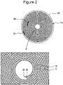
- Figure 2 is a lateral direction (radius direction) cross-sectional view showing the winding-start side end portion of the electrode body 14 and the vicinity thereof.
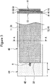
- Figure 3 is a view showing winding-start side end portions of the positive electrode 11 and the negative electrode 12 forming the electrode body 14.
- the separators 13 are omitted.
- the positive electrode 11 includes a belt-shaped positive electrode collector 30 and positive electrode mixture layers 31 formed on two surfaces of the positive electrode collector 30.
- the positive electrode collector 30 for example, foil made from a metal, such as aluminum, stable in a potential range of the positive electrode 11 or a film having a surface layer formed of the metal mentioned above may be used.
- the positive electrode mixture layer 31 contains a positive electrode active material, an electrically conductive agent, and a binding agent.
- the positive electrode 11 can be formed, for example, such that after a positive electrode mixture slurry containing the positive electrode active material, the electrically conductive agent, the binding agent, and the like is applied to the positive electrode collector 30, coating films thus formed are dried and then pressed to form the positive electrode mixture layers 31 on the two surfaces of the positive electrode collector 30.
- the positive electrode active material is composed of a lithium metal composite oxide as a primary component.
- a metal element contained in the lithium metal composite oxide for example, there may be mentioned Ni, Co, Mn, Al, B, Mg, Ti, V, Cr, Fe, Cu, Zn, Ga, Sr, Zr, Nb, In, Sn, Ta, or W.
- a preferable example of the lithium metal composite oxide is a composite oxide containing at least one of Ni, Co, Mn, and Al.
- inorganic compound particles of aluminum oxide, a lanthanoid-containing compound, or the like may be tightly fixed.
- the electrically conductive agent contained in the positive electrode mixture layer 31 for example, there may be mentioned a carbon material, such as carbon black, acetylene black, Ketjen black, or graphite.
- a fluorine resin such as a polytetrafluoroethylene (PTFE) or a poly(vinylidene fluoride) (PVdF), a polyacrylonitrile (PAN), a polyimide resin, an acrylic resin, or a polyolefin resin.
- PTFE polytetrafluoroethylene
- PVdF poly(vinylidene fluoride)
- PAN polyacrylonitrile
- a polyimide resin an acrylic resin
- a polyolefin resin Those resins each may be used together with a cellulose derivative, such as a carboxymethyl cellulose (CMC) or its salt, or a polyethylene oxide (PEO).
- CMC carboxymethyl cellulose
- PEO polyethylene oxide
- the negative electrode 12 includes a belt-shaped negative electrode collector 40 and negative electrode mixture layers 41 formed on two surfaces of the negative electrode collector 40.
- the negative electrode collector 40 for example, foil made from a metal, such as copper, stable in a potential range of the negative electrode 12 or a film having a surface layer formed of the metal mentioned above may be used.
- the negative electrode mixture layer 41 contains a negative electrode active material and a binding agent.
- the negative electrode 12 can be formed, for example, such that after a negative electrode mixture slurry containing the negative electrode active material, the binding agent, and the like is applied to the negative electrode collector 40, coating films thus formed are dried and then pressed to form the negative electrode mixture layers 41 on the two surfaces of the negative electrode collector 40.
- the negative electrode mixture layer 41 as the negative electrode active material, a silicon compound capable of reversibly occluding and releasing lithium ions is contained. Furthermore, the negative electrode mixture layer 41 contains as the negative electrode active material, a natural graphite, such as a flaky graphite, a massive graphite, or an earthy graphite, or an artificial graphite, such as a massive artificial graphite (MAG) or graphitized mesophase carbon microbeads (MCMB).
- the content of the silicon compound in the negative electrode mixture layer 41 is with respect to the total mass of the negative electrode active material, for example, 6 to 15 percent by mass and preferably 7 to 10 percent by mass.
- a mixing ratio of the silicon compound to the graphite is, for example, 6: 94 to 15: 85 and preferably 7: 93 to 10: 90.
- a metal which is not Si and which forms an alloy with lithium, an alloy containing the above metal, or a compound containing the above metal may also be used.
- an electrically conductive agent such as carbon black, may be added to the negative electrode mixture layer 41.
- the silicon compound described above is a silicon oxide represented by SiO x .
- the silicon oxide represented by SiO x has the structure in which, for example, Si fine particles are dispersed in an amorphous SiO 2 matrix.
- the silicon oxide is SiO x where 0.5 ⁇ x ⁇ 1.6.
- a silicon compound represented by Li 2y SiO (2+y) (0 ⁇ y ⁇ 2) having the structure in which Si fine particles are dispersed in a lithium silicate phase may also be mentioned by way of example.
- electrically conductive films each composed of a material having a high electrical conductivity as compared to that of the silicon oxide are preferably formed.
- a constituent material of the electrically conductive film at least one selected from a carbon material, a metal, and a metal compound may be mentioned by way of example.
- a carbon material such as amorphous carbon, is preferable.
- a carbon film may be formed, for example, by a CVD method using acetylene, methane, or the like, or by a method in which after a coal pitch, a petroleum pitch, a phenol resin, or the like is mixed with SiO x particles, a heat treatment is performed.
- the electrically conductive film may be formed by fixing an electrically conductive filler, such as carbon black, to the particle surfaces of SiO x using a binding agent.
- the electrically conductive film is formed, for example, in an amount of 0.5 to 10 percent by mass with respect to the mass of the SiO x particles.
- a fluorine resin, a PAN, a polyimide resin, an acrylic resin, or a polyolefin resin may be used.
- a fluorine resin, a PAN, a polyimide resin, an acrylic resin, or a polyolefin resin may be used.
- a dispersion of a styrene-butadiene rubber (SBR), a polyacrylic acid (PAA) or its salt, or a poly(vinyl alcohol) is preferably used.
- a porous sheet having an ion permeability and an insulating property may be used.
- a porous sheet for example, a fine porous thin film, a woven cloth, or a non-woven cloth may be mentioned.
- an olefin resin such as a polyethylene or a polypropylene, or a cellulose is preferable.
- the separator 13 may have either a monolayer structure or a multilayer structure. On a surface of the separator 13, for example, a heat resistant layer may also be provided.
- the electrode body 14 is a winding type electrode body in which the positive electrode 11 and the negative electrode 12 are spirally wound with the separators 13 interposed therebetween.
- the negative electrode 12 is formed one size larger than the positive electrode 11.
- a winding-start side end 42 of the negative electrode mixture layer 41 extends to a winding-start end side of the electrode body 14 past a winding-start side end 32 of the positive electrode mixture layer 31. That is, at the winding-start side end portion of the negative electrode 12, a non-facing portion 44 not facing the positive electrode 11 is formed.
- the negative electrode 12 may form a winding-start end of the electrode body 14, in general, a winding-start side end of the separator 13 extends to the winding-start end side of the electrode body 14 past a winding-start side end of the negative electrode 12. That is, the winding-start side end of the separator 13 is located at the winding-start end of the electrode body 14.
- the winding-start side end 32 of the positive electrode mixture layer 31 is located at a winding-start side end of the positive electrode 11, and the winding-start side end 42 of the negative electrode mixture layer 41 is located at the winding-start side end of the negative electrode 12. That is, the winding-start side end 32 of the positive electrode mixture layer 31 coincides with a winding-start side end of the positive electrode collector 30, and the winding-start side end 42 of the negative electrode mixture layer coincides with a winding-start side end of the negative electrode collector 40.
- an exposed portion at which the positive electrode mixture layer 31 is not formed and at which the surface of the positive electrode collector 30 is exposed may be provided.
- an exposed portion may be provided at the winding-start side end portion of the negative electrode 12 at which the surface of the negative electrode collector 40 is exposed.
- electrode tabs may be connected.
- a length Y, in mm, of a portion of the negative electrode mixture layer 41 extending from the winding-start side end 32 of the positive electrode mixture layer 31 in a winding direction (circumferential direction) of the electrode body 14 and a rate X, in percent by mass, of the silicon oxide with respect to the total mass of the negative electrode active material satisfy the relationship of the following Equation 1.
- the length Y is, in other words, a length of the non-facing portion 44 of the negative electrode 12 in the longitudinal direction.
- the length Y is increased as the rate X of the silicon oxide is increased and is decreased as the rate Y is decreased.
- a strain stress generated by the difference in volume expansion between the facing portion 43 of the negative electrode mixture layer 41 facing the positive electrode 11 and the non-facing portion 44 of the negative electrode mixture layer 41 not facing the positive electrode 11 is liable to be concentrated.
- the strain stress to be applied to the width-direction central portion R of the non-facing portion 44 is efficiently dispersed, and the deformation of the negative electrode 12 can be suppressed.
- Equation 1 The relationship represented by Equation 1 is satisfied when the rate X of the silicon oxide with respect to the total mass of the negative electrode active material is in a range of 6 to 15 percent by mass.
- the rate X is less than 6 percent by mass, even if the length Y is small, the deformation of the negative electrode 12 is not generated.
- the rate X is more than 15 percent by mass, even if the length Y is larger than 30 mm, an effect of reducing a stress is decreased with respect to an increase in strain stress, and hence, the deformation of the negative electrode 12 cannot be sufficiently suppressed.
- Equation 1 defines approximately the minimum necessary length Y of the non-facing portion 44, and the upper value of Y may be arbitrarily determined in accordance with a design capacity of the battery or the like.
- the silicon oxide particles on which the carbon films were provided could be obtained by the following method.
- the winding core was removed, so that a winding type electrode body was formed.
- the positive electrode, the negative electrode, and the separators were spirally wound around the winding core so that the negative electrode extended from a winding-start side end of the positive electrode to have a length Y (length Y of a non-facing portion) of 6 mm from a winding-start side end of the positive electrode mixture layer to a winding-start side end of the negative electrode mixture layer.
- LiPF 6 was dissolved in a mixed solvent in which ethylene carbonate (EC) and dimethyl carbonate (DMC) were mixed together at a volume ratio of 25/75 (at one atmospheric pressure and 25°C), LiPF 6 was dissolved to obtain a concentration of 1 mol/L, so that a nonaqueous electrolyte solution was prepared.
- EC ethylene carbonate
- DMC dimethyl carbonate
- the winding type electrode body was inserted in a cylindrical iron-made exterior package can. After a welding rod was inserted in a hollow portion of the electrode body which was formed after the winding core was removed and was brought into contact with the negative electrode tab, the negative electrode tab was resistance-welded to an inner surface of a bottom portion of the exterior package can. After the nonaqueous electrolyte liquid was charged in the exterior package can, the positive electrode tab was welded to a sealing body, and an opening portion of the exterior package can was sealed by the sealing body, so that a cylindrical nonaqueous electrolyte secondary battery having a diameter of 18 mm and a height of 65 mm was formed.
- the battery described above was charged at a constant current of 0.3 It until a battery voltage reached 4.2 V and was further charged at a constant voltage of 4.2 V until a current reached 0.02 It. After the charge, the battery was discharged at a constant current of 0.5 It until the battery voltage reached 2.5 V. The initial charge/discharge was performed at room temperature.
- Example 1 Except for that the content (percent by mass) of the silicon oxide with respect to the negative electrode active material and the length Y from the winding-start side end of the positive electrode to a winding-start side end of the negative electrode were changed to the values shown in Table 1, a nonaqueous electrolyte secondary battery was formed in a manner similar to that of Example 1. In addition, the performance evaluation was also performed in a manner similar to that of Example 1.
- the negative electrode mixture layer at the non-facing portion is not volume-expanded by charge, and hence, it is supposed that the non-facing portion is pulled by the stress of the facing portion, and a large strain stress is applied to the width-direction central portion of the non-facing portion.
- nonaqueous electrolyte secondary battery 11 positive electrode, 12 negative electrode, 13 separator, 14 electrode body, 15 battery case, 16 exterior package can, 17 sealing body, 18, 19 insulating plate, 20 positive electrode tab, 21 negative electrode tab, 22 groove portion, 23 filter, 24 lower valve, 25 insulating member, 26 upper valve, 27 cap, 28 gasket, 30 positive electrode collector, 31 positive electrode mixture layer, 32, 42 winding-start side end, 40 negative electrode collector, 41 negative electrode mixture layer, 43 facing portion, 44 non-facing portion
Landscapes
- Chemical & Material Sciences (AREA)
- Chemical Kinetics & Catalysis (AREA)
- Electrochemistry (AREA)
- General Chemical & Material Sciences (AREA)
- Engineering & Computer Science (AREA)
- Manufacturing & Machinery (AREA)
- Composite Materials (AREA)
- Materials Engineering (AREA)
- Inorganic Chemistry (AREA)
- Secondary Cells (AREA)
- Battery Electrode And Active Subsutance (AREA)
Description
- The present invention relates to a nonaqueous electrolyte secondary battery.
- It has been known that, compared to a carbon-based material such as graphite, a silicon compound, such as a silicon oxide represented by SiOx, is able to occlude a large amount of lithium ions per unit volume. For example,
PTL 1 has disclosed a nonaqueous electrolyte secondary battery using a silicon compound as a negative electrode active material. In the battery disclosed inPTL 1, as the negative electrode active material, a silicon compound and graphite are used in combination. - PTL 1:
Japanese Published Unexamined Patent Application No. 2010-212228 -
US 2011/076534 A1 discloses a lithium ion secondary battery comprising a winding type electrode body in which a positive electrode including a positive electrode mixture layer and a negative electrode including a negative electrode mixture layer are spirally wound with at least one separator interposed therebetween, wherein the negative electrode mixture layer contains, as negative electrode active material, a material capable of forming an alloy with lithium such as silicon or a silicon alloy containing 50 % by atom or more of silicon atoms. - Incidentally, since a silicon compound has a large volume expansion caused by insertion of lithium ions as compared to that of graphite, when the silicon compound is used as a negative electrode active material, a strain stress is liable to be generated in a negative electrode. In particular, when a rate of the silicon compound in the negative electrode active material is increased, a large strain stress is applied to the negative electrode, and the negative electrode may be deformed in some cases. In addition, by an influence of the deformation of the negative electrode, a positive electrode and a separator may also be deformed in some cases.
- In a nonaqueous electrolyte secondary battery using graphite and a silicon compound as a negative electrode active material, the present invention aims to suppress the deformation of a negative electrode.
- A nonaqueous electrolyte secondary battery according to the present invention is a nonaqueous electrolyte secondary battery which comprises: a winding type electrode body in which a positive electrode including a positive electrode mixture layer and a negative electrode including a negative electrode mixture layer are spirally wound with at least one separator interposed therebetween. According to the nonaqueous electrolyte secondary battery of the present invention, in the negative electrode mixture layer, graphite and a silicon oxide represented by SiOx, where 0.5≤x≤1.6, are contained as a negative electrode active material; a winding-start side end of the negative electrode mixture layer extends to a winding-start end side of the electrode body past a winding-start side end of the positive electrode mixture layer; and a length Y, in mm, of a portion of the negative electrode mixture layer extending from the winding-start side end of the positive electrode mixture layer and a rate X, in percent by mass, of the silicon oxide with respect to the total mass of the negative electrode active material satisfy a relationship of Y>3X-15, where 6≤X≤15.
- The present invention is defined by
claim 1. - According to the present invention, in the nonaqueous electrolyte secondary battery using graphite and a silicon oxide as the negative electrode active material, the deformation of the negative electrode can be suppressed. Brief Description of Drawings
-
- [
Figure 1] Figure 1 is a longitudinal direction cross-sectional view of a nonaqueous electrolyte secondary battery according to one example of an embodiment. - [
Figure 2] Figure 2 is a lateral direction cross-sectional view partially showing an electrode body according to one example of the embodiment. - [
Figure 3] Figure 3 is a view showing a positive electrode and a negative electrode according to one example of the embodiment. - [
Figure 4] Figure 4 is a graph showing a relationship between a length Y of a non-facing portion and a rate X of a silicon compound. - As described above, since a silicon compound has a large volume expansion by insertion of lithium ions, when the silicon compound is used as a negative electrode active material, a strain stress is liable to be generated in a negative electrode. When the negative electrode is deformed, a risk to cause an internal short circuit is increased; hence, to suppress the deformation of the negative electrode is an important subject. In addition, since the negative electrode is generally formed one size larger than a positive electrode, a portion (non-facing portion) not facing the positive electrode is present at a winding-start side end portion of the negative electrode of a winding type electrode body. Although a negative electrode mixture layer is volume-expanded by charge at a facing portion of the negative electrode facing the positive electrode, the negative electrode mixture layer at the non-facing portion is not volume-expanded by charge. Hence, the non-facing portion is pulled by a stress of the facing portion, and a strain stress is applied to the non-facing portion. It is believed that since this strain stress is concentrated on a width-direction central portion of the non-facing portion, in particular, on a boundary between the facing portion and the non-facing portion, the negative electrode is deformed at this width-direction central portion.
- Through intensive research carried out by the present inventors to overcome the problem described above, it was found that when a length Y from a winding-start side end of a positive electrode mixture layer to a winding-start side end of the negative electrode mixture layer and a rate X of the silicon compound with respect to the total mass of the negative electrode active material satisfy a relationship of Y>3X-15, where 6≤X≤15, the strain stress at the non-facing portion of the negative electrode can be dispersed, and the deformation of the negative electrode can be suppressed. It is believed that when the relationship of Y>3X-15, where 6≤X≤15, is satisfied, the strain stress applied to the non-facing portion of the negative electrode is dispersed, and hence, the deformation of the negative electrode is suppressed.
- Hereinafter, one example of the embodiment of the present invention will be described in detail. In the following description, although a cylindrical battery in which a winding
type electrode body 14 is received in acylindrical battery case 15 will be described by way of example, the battery case is not limited to a cylindrical case and may be, for example, a square case or a battery case formed from a laminate sheet which contains at least one metal layer and at least one resin layer. In the present specification, for the convenience of illustration, a sealingbody 17 side of thebattery case 15 is described as "upper (side)", and a bottom portion side of an exterior package can 16 will be described as "lower (side)". -
Figure 1 is a longitudinal direction (axial direction) cross-sectional view of a nonaqueous electrolytesecondary battery 10 according to one example of the embodiment. As shown inFigure 1 by way of example, the nonaqueous electrolytesecondary battery 10 includes anelectrode body 14, a nonaqueous electrolyte (not shown), and abattery case 15 which receives theelectrode body 14 and the nonaqueous electrolyte. Theelectrode body 14 has a winding structure in which apositive electrode 11 and anegative electrode 12 are spirally wound with at least oneseparator 13 interposed therebetween. Thebattery case 15 is formed of a bottom-closed exterior package can 16 and a sealingbody 17 which seals an opening portion of the exterior package can 16. In addition, the nonaqueous electrolytesecondary battery 10 also includes a resin-madegasket 28 disposed between the exterior package can 16 and the sealingbody 17. - The nonaqueous electrolyte contains a nonaqueous solvent and an electrolyte salt dissolved in the nonaqueous solvent. As the nonaqueous solvent, for example, there may be mentioned an ester, an ether, a nitrile, an amide, or a mixed solvent containing at least two of those mentioned above. The nonaqueous solvent may also include a halogen substituent in which at least one hydrogen atom of each of those solvents mentioned above is replaced by a halogen atom, such as fluorine. In addition, the nonaqueous electrolyte is not limited to a liquid electrolyte, and a solid electrolyte using a gel polymer or the like may also be used. As the electrolyte salt, for example, a lithium salt, such as LiPF6, is used.
- The
electrode body 14 is formed of a longpositive electrode 11, a longnegative electrode 12, twolong separators 13, apositive electrode tab 20 bonded to thepositive electrode 11, and anegative electrode tab 21 bonded to thenegative electrode 12. In order to prevent precipitation of lithium, thenegative electrode 12 is formed one size larger than thepositive electrode 11. That is, thenegative electrode 12 is formed longer than thepositive electrode 11 in a longitudinal direction and in a width direction (short direction). The twoseparators 13 are each formed at least one size larger than thepositive electrode 11, for example, so as to sandwich thepositive electrode 11. - In this embodiment, the
positive electrode tab 20 is provided at a central portion of thepositive electrode 11 in a longitudinal direction and at a position apart from a winding-start side end portion and a winding-finish side end portion of theelectrode body 14. On the other hand, thenegative electrode tab 21 is provided at one end portion of thenegative electrode 12 in a longitudinal direction which is located at a winding-finish side of theelectrode body 14. - On the top and the bottom of the
electrode body 14,insulating plates Figure 1 , thepositive electrode tab 20 fitted to thepositive electrode 11 extends to a sealingbody 17 side through a through-hole of theinsulating plate 18, and thenegative electrode tab 21 fitted to thenegative electrode 12 extends to a bottom portion side of the exterior package can 16 along the outside of theinsulating plate 19. Thepositive electrode tab 20 is connected to a bottom surface of afilter 23 functioning as a bottom plate of the sealingbody 17 by welding or the like, and acap 27 functioning as a top plate of the sealingbody 17 electrically connected to thefilter 23 is used as a positive electrode terminal. Thenegative electrode tab 21 is connected to an inner surface of the bottom portion of the exterior package can 16 by welding or the like, and the exterior package can 16 is used as a negative electrode terminal. - The exterior package can 16 is, for example, a bottom-closed cylindrical metal-made container. As described above, between the exterior package can 16 and the sealing
body 17, thegasket 28 is provided, and an inner space of thebattery case 15 is sealed. The exterior package can 16 has a groove portion 22 to support the sealingbody 17, the groove portion being formed, for example, by pressing a side surface portion from the outside. The groove portion 22 is preferably formed to have a ring shape along a circumferential direction of the exterior package can 16, and an upper surface of the groove portion 22 supports the sealingbody 17. In addition, an upper end portion of the exterior package can 16 is bent inside and is caulked with a circumferential portion of the sealingbody 17. - The sealing
body 17 has the structure in which thefilter 23, alower valve 24, aninsulating member 25, anupper valve 26, and thecap 27 are laminated in this order from anelectrode body 14 side. The members forming the sealingbody 17 each have, for example, a disc shape or a ring shape and are electrically connected to each other except for the insulatingmember 25. Thelower valve 24 and theupper valve 26 are connected to each other at the central portions thereof, and between the peripheral portions thereof, theinsulating member 25 is provided. When an inside pressure of the battery is increased by abnormal heat generation, since thelower valve 24 is deformed so as to push up theupper valve 26 toward acap 27 side and is fractured, an electric current path between thelower valve 24 and theupper valve 26 is interrupted. When the inside pressure is further increased, theupper valve 26 is fractured, and a gas is exhausted from an opening portion of thecap 27. - Hereinafter, with appropriate reference to
Figures 2 and3 , theelectrode body 14 will be described in detail.Figure 2 is a lateral direction (radius direction) cross-sectional view showing the winding-start side end portion of theelectrode body 14 and the vicinity thereof.Figure 3 is a view showing winding-start side end portions of thepositive electrode 11 and thenegative electrode 12 forming theelectrode body 14. InFigures 2 and3 , theseparators 13 are omitted. - As shown in
Figures 2 and3 , thepositive electrode 11 includes a belt-shapedpositive electrode collector 30 and positive electrode mixture layers 31 formed on two surfaces of thepositive electrode collector 30. For thepositive electrode collector 30, for example, foil made from a metal, such as aluminum, stable in a potential range of thepositive electrode 11 or a film having a surface layer formed of the metal mentioned above may be used. The positiveelectrode mixture layer 31 contains a positive electrode active material, an electrically conductive agent, and a binding agent. Thepositive electrode 11 can be formed, for example, such that after a positive electrode mixture slurry containing the positive electrode active material, the electrically conductive agent, the binding agent, and the like is applied to thepositive electrode collector 30, coating films thus formed are dried and then pressed to form the positive electrode mixture layers 31 on the two surfaces of thepositive electrode collector 30. - The positive electrode active material is composed of a lithium metal composite oxide as a primary component. As a metal element contained in the lithium metal composite oxide, for example, there may be mentioned Ni, Co, Mn, Al, B, Mg, Ti, V, Cr, Fe, Cu, Zn, Ga, Sr, Zr, Nb, In, Sn, Ta, or W. A preferable example of the lithium metal composite oxide is a composite oxide containing at least one of Ni, Co, Mn, and Al. In addition, onto particle surfaces of the lithium metal composite oxide, inorganic compound particles of aluminum oxide, a lanthanoid-containing compound, or the like may be tightly fixed.
- As the electrically conductive agent contained in the positive
electrode mixture layer 31, for example, there may be mentioned a carbon material, such as carbon black, acetylene black, Ketjen black, or graphite. As the binding agent contained in the positiveelectrode mixture layer 31, for example, there may be mentioned a fluorine resin, such as a polytetrafluoroethylene (PTFE) or a poly(vinylidene fluoride) (PVdF), a polyacrylonitrile (PAN), a polyimide resin, an acrylic resin, or a polyolefin resin. Those resins each may be used together with a cellulose derivative, such as a carboxymethyl cellulose (CMC) or its salt, or a polyethylene oxide (PEO). - The
negative electrode 12 includes a belt-shapednegative electrode collector 40 and negative electrode mixture layers 41 formed on two surfaces of thenegative electrode collector 40. For thenegative electrode collector 40, for example, foil made from a metal, such as copper, stable in a potential range of thenegative electrode 12 or a film having a surface layer formed of the metal mentioned above may be used. The negativeelectrode mixture layer 41 contains a negative electrode active material and a binding agent. Thenegative electrode 12 can be formed, for example, such that after a negative electrode mixture slurry containing the negative electrode active material, the binding agent, and the like is applied to thenegative electrode collector 40, coating films thus formed are dried and then pressed to form the negative electrode mixture layers 41 on the two surfaces of thenegative electrode collector 40. - In the negative
electrode mixture layer 41, as the negative electrode active material, a silicon compound capable of reversibly occluding and releasing lithium ions is contained. Furthermore, the negativeelectrode mixture layer 41 contains as the negative electrode active material, a natural graphite, such as a flaky graphite, a massive graphite, or an earthy graphite, or an artificial graphite, such as a massive artificial graphite (MAG) or graphitized mesophase carbon microbeads (MCMB). The content of the silicon compound in the negativeelectrode mixture layer 41 is with respect to the total mass of the negative electrode active material, for example, 6 to 15 percent by mass and preferably 7 to 10 percent by mass. A mixing ratio of the silicon compound to the graphite is, for example, 6: 94 to 15: 85 and preferably 7: 93 to 10: 90. - In an example not covered by the claimed invention, for the negative electrode active material, a metal which is not Si and which forms an alloy with lithium, an alloy containing the above metal, or a compound containing the above metal may also be used. In said example not covered by the claimed invention, when a material, such as lithium titanate, having a low electric conductivity is used as the negative electrode active material, an electrically conductive agent, such as carbon black, may be added to the negative
electrode mixture layer 41. - In the present invention, the silicon compound described above is a silicon oxide represented by SiOx. The silicon oxide represented by SiOx has the structure in which, for example, Si fine particles are dispersed in an amorphous SiO2 matrix. In the present invention, the silicon oxide is SiOx where 0.5≤x≤1.6.
- In an alternative not covered by the claimed invention, a silicon compound represented by Li2ySiO(2+y) (0<y<2) having the structure in which Si fine particles are dispersed in a lithium silicate phase may also be mentioned by way of example.
- On the particle surfaces of the silicon oxide represented by SiOx, electrically conductive films each composed of a material having a high electrical conductivity as compared to that of the silicon oxide are preferably formed. As a constituent material of the electrically conductive film, at least one selected from a carbon material, a metal, and a metal compound may be mentioned by way of example. Among those mentioned above, a carbon material, such as amorphous carbon, is preferable. A carbon film may be formed, for example, by a CVD method using acetylene, methane, or the like, or by a method in which after a coal pitch, a petroleum pitch, a phenol resin, or the like is mixed with SiOx particles, a heat treatment is performed. In addition, the electrically conductive film may be formed by fixing an electrically conductive filler, such as carbon black, to the particle surfaces of SiOx using a binding agent. The electrically conductive film is formed, for example, in an amount of 0.5 to 10 percent by mass with respect to the mass of the SiOx particles.
- For the binding agent contained in the negative
electrode mixture layer 41, as is the case of thepositive electrode 11, for example, a fluorine resin, a PAN, a polyimide resin, an acrylic resin, or a polyolefin resin may be used. When the mixture slurry is prepared using an aqueous solvent, for example, a CMC or its salt, a dispersion of a styrene-butadiene rubber (SBR), a polyacrylic acid (PAA) or its salt, or a poly(vinyl alcohol) is preferably used. - For the
separator 13, a porous sheet having an ion permeability and an insulating property may be used. As a particular example of the porous sheet, for example, a fine porous thin film, a woven cloth, or a non-woven cloth may be mentioned. As a material of theseparator 13, for example, an olefin resin, such as a polyethylene or a polypropylene, or a cellulose is preferable. Theseparator 13 may have either a monolayer structure or a multilayer structure. On a surface of theseparator 13, for example, a heat resistant layer may also be provided. - The
electrode body 14 is a winding type electrode body in which thepositive electrode 11 and thenegative electrode 12 are spirally wound with theseparators 13 interposed therebetween. In order to prevent precipitation of lithium on the surface of thenegative electrode 12, thenegative electrode 12 is formed one size larger than thepositive electrode 11. Hence, a winding-start side end 42 of the negativeelectrode mixture layer 41 extends to a winding-start end side of theelectrode body 14 past a winding-start side end 32 of the positiveelectrode mixture layer 31. That is, at the winding-start side end portion of thenegative electrode 12, anon-facing portion 44 not facing thepositive electrode 11 is formed. In addition, although thenegative electrode 12 may form a winding-start end of theelectrode body 14, in general, a winding-start side end of theseparator 13 extends to the winding-start end side of theelectrode body 14 past a winding-start side end of thenegative electrode 12. That is, the winding-start side end of theseparator 13 is located at the winding-start end of theelectrode body 14. - In this embodiment, the winding-start side end 32 of the positive
electrode mixture layer 31 is located at a winding-start side end of thepositive electrode 11, and the winding-start side end 42 of the negativeelectrode mixture layer 41 is located at the winding-start side end of thenegative electrode 12. That is, the winding-start side end 32 of the positiveelectrode mixture layer 31 coincides with a winding-start side end of thepositive electrode collector 30, and the winding-start side end 42 of the negative electrode mixture layer coincides with a winding-start side end of thenegative electrode collector 40. - At the winding-start side end portion of the
positive electrode 11, an exposed portion at which the positiveelectrode mixture layer 31 is not formed and at which the surface of thepositive electrode collector 30 is exposed may be provided. As is the case described above, an exposed portion may be provided at the winding-start side end portion of thenegative electrode 12 at which the surface of thenegative electrode collector 40 is exposed. To those exposed portions, electrode tabs may be connected. In addition, even in the case in which the end of the collector does not coincide with the end of the mixture layer, the relationship represented by thefollowing equation 1 is required to be satisfied. - A length Y, in mm, of a portion of the negative
electrode mixture layer 41 extending from the winding-start side end 32 of the positiveelectrode mixture layer 31 in a winding direction (circumferential direction) of theelectrode body 14 and a rate X, in percent by mass, of the silicon oxide with respect to the total mass of the negative electrode active material satisfy the relationship of the followingEquation 1. The length Y is, in other words, a length of thenon-facing portion 44 of thenegative electrode 12 in the longitudinal direction.
- The length Y is increased as the rate X of the silicon oxide is increased and is decreased as the rate Y is decreased. As described above, on a width-direction central portion R of the
non-facing portion 44 of thenegative electrode 12, a strain stress generated by the difference in volume expansion between the facingportion 43 of the negativeelectrode mixture layer 41 facing thepositive electrode 11 and thenon-facing portion 44 of the negativeelectrode mixture layer 41 not facing thepositive electrode 11 is liable to be concentrated. In the nonaqueous electrolytesecondary battery 10, when the length Y is appropriately set in accordance with the rate X based onEquation 1, the strain stress to be applied to the width-direction central portion R of thenon-facing portion 44 is efficiently dispersed, and the deformation of thenegative electrode 12 can be suppressed. - The relationship represented by
Equation 1 is satisfied when the rate X of the silicon oxide with respect to the total mass of the negative electrode active material is in a range of 6 to 15 percent by mass. When the rate X is less than 6 percent by mass, even if the length Y is small, the deformation of thenegative electrode 12 is not generated. On the other hand, when the rate X is more than 15 percent by mass, even if the length Y is larger than 30 mm, an effect of reducing a stress is decreased with respect to an increase in strain stress, and hence, the deformation of thenegative electrode 12 cannot be sufficiently suppressed. -
Figure 4 is a graph showing the relationship between the rate X (percent by mass) of the silicon oxide along the horizontal axis and the length Y of thenon-facing portion 44 along the vertical axis, and the results of the following Examples and Comparative Examples are plotted. Examples in which the deformation of thenegative electrode 12 was not confirmed are plotted by ●, and Comparative Examples in which the deformation of thenegative electrode 12 was confirmed are plotted by ×. As shown inFigure 4 , as the rate X of the silicon oxide is increased, although the length Y of thenon-facing portion 44 is required to be increased, as long as the length Y of the non-facing portion at least satisfies the relationship of Y=3X-15, the deformation of thenegative electrode 12 is suppressed. Hence, when X and Y satisfy the condition of Equation 1: Y≥3X-15 (6≤X≤15), the deformation of thenegative electrode 12 is suppressed.Equation 1 defines approximately the minimum necessary length Y of thenon-facing portion 44, and the upper value of Y may be arbitrarily determined in accordance with a design capacity of the battery or the like. - Hereinafter, although the present invention will be further described with reference to Examples, the present invention is not limited to the following Examples.
- After lithium hydroxide and a nickel composite oxide represented by Ni0.82Co0.15Al0.03O2 were mixed together so that a rate of the number of moles of Li with respect to the number of total moles of metal elements of the above composite oxide was 1.015, firing was performed in an oxygen atmosphere, so that a lithium nickel composite oxide (positive electrode active material) represented by LiNi0.82Co0.15Al0.03O2 was synthesized.
- After 100 parts by mass of the positive electrode active material, 1 part by mass of acetylene black, and 0.9 parts by mass of a poly(vinylidene fluoride) were mixed together, an appropriate amount of N-methyl-2-pyrrolidone was added, so that a positive electrode mixture slurry was prepared. Subsequently, this positive electrode mixture slurry was applied on two surfaces of a long positive electrode collector formed of aluminum foil having a thickness of 15 µm by a doctor blade method, and coating films thus formed were then dried. After the dried coating films were pressed using a roller machine, cutting was performed to obtain a predetermined electrode size, so that a positive electrode in which positive electrode mixture layers were formed on the two surfaces of the positive electrode collector was formed. At a central portion of the positive electrode in a longitudinal direction thereof, an exposed portion at which the mixture layers were not present and at which the collector surface was exposed was provided, and an aluminum-made positive electrode tab was welded to the exposed portion.
- After 93 parts by mass of a graphite powder, 7 parts by mass of particles of a silicon oxide represented by SiO (SiOx, x=1), the surfaces of the particles each being provided with a carbon film, 1.5 parts by mass of a sodium carboxymethyl cellulose, and 1 part by mass of a dispersion of a styrene-butadiene rubber were mixed together, an appropriate amount of water was added, so that a negative electrode mixture slurry was prepared. Subsequently, the negative electrode mixture slurry was applied on two surfaces of a long negative electrode collector formed of copper foil having a thickness of 8 µm, and coating films thus formed were then dried. After the dried coating films were pressed using a roller machine, cutting was performed to obtain a predetermined electrode size, so that a negative electrode in which negative electrode mixture layers were formed on the two surfaces of the negative electrode collector was formed. An exposed portion at which the mixture layers were not present and at which the collector surface was exposed was provided at one end portion (end portion located at a winding-finish side of an electrode body) of the negative electrode in a longitudinal direction thereof, and a nickel-made negative electrode tab was welded to the exposed portion.
- The silicon oxide particles on which the carbon films were provided could be obtained by the following method.
- First, by a CVD method using a hydrocarbon-based gas, carbon films were formed on the surfaces of the particles of a silicon oxide having a SiO composition. Subsequently, the SiO particles on which the carbon films were formed were heated at 1,000°C in an argon atmosphere to perform a disproportionation reaction, so that a Si phase and a SiO2 phase were formed in the SiO particles. The particles described above were classified, so that a silicon oxide to be used for a negative electrode active material was obtained.
- After the above positive electrode and the above negative electrode were spirally wound around a winding core (diameter: 3.3φ) with separators each formed of a polyethylene-made fine porous film interposed therebetween, the winding core was removed, so that a winding type electrode body was formed. In this step, the positive electrode, the negative electrode, and the separators were spirally wound around the winding core so that the negative electrode extended from a winding-start side end of the positive electrode to have a length Y (length Y of a non-facing portion) of 6 mm from a winding-start side end of the positive electrode mixture layer to a winding-start side end of the negative electrode mixture layer.
- In a mixed solvent in which ethylene carbonate (EC) and dimethyl carbonate (DMC) were mixed together at a volume ratio of 25/75 (at one atmospheric pressure and 25°C), LiPF6 was dissolved to obtain a concentration of 1 mol/L, so that a nonaqueous electrolyte solution was prepared.
- The winding type electrode body was inserted in a cylindrical iron-made exterior package can. After a welding rod was inserted in a hollow portion of the electrode body which was formed after the winding core was removed and was brought into contact with the negative electrode tab, the negative electrode tab was resistance-welded to an inner surface of a bottom portion of the exterior package can. After the nonaqueous electrolyte liquid was charged in the exterior package can, the positive electrode tab was welded to a sealing body, and an opening portion of the exterior package can was sealed by the sealing body, so that a cylindrical nonaqueous electrolyte secondary battery having a diameter of 18 mm and a height of 65 mm was formed.
- The battery described above was charged at a constant current of 0.3 It until a battery voltage reached 4.2 V and was further charged at a constant voltage of 4.2 V until a current reached 0.02 It. After the charge, the battery was discharged at a constant current of 0.5 It until the battery voltage reached 2.5 V. The initial charge/discharge was performed at room temperature.
- After the battery processed by the above initial charge/discharge was charged under the same charge conditions as those of the initial charge/discharge, the charged battery was disassembled, and the negative electrode was recovered. A winding-start side end portion of the negative electrode thus recovered and the vicinity thereof were observed by visual inspection, and the presence or absence of the deformation was evaluated. The evaluation results are shown in Table 1.
- Except for that the content (percent by mass) of the silicon oxide with respect to the negative electrode active material and the length Y from the winding-start side end of the positive electrode to a winding-start side end of the negative electrode were changed to the values shown in Table 1, a nonaqueous electrolyte secondary battery was formed in a manner similar to that of Example 1. In addition, the performance evaluation was also performed in a manner similar to that of Example 1.
[Table 1] RATE X (wt%) LENGTH Y (mm) DEFORMATION OF NEGATIVE ELECTRODE EXAMPLE 1 7 6 NO EXAMPLE 2 9 12 NO EXAMPLE 3 10 15 NO COMPARATIVE EXAMPLE 1 7 3 YES COMPARATIVE EXAMPLE 2 8 3 YES COMPARATIVE EXAMPLE 3 9 3 YES COMPARATIVE EXAMPLE 4 9 6 YES COMPARATIVE EXAMPLE 5 10 6 YES - As shown in Table 1 and
Figure 4 , in the negative electrode of each of Comparative Examples 1 to 5 in which the condition of Equation 1: Y≥3X-15 was not satisfied, crack lines (deformation) were confirmed in the negative electrode mixture layer at a width-direction central portion of the non-facing portion. It is believed that this deformation is generated such that a strain stress is applied to the negative electrode due to a large volume expansion of the silicon compound, and this stress is concentrated on the width-direction central portion of the non-facing portion. As described above, at the facing portion of the negative electrode, although the negative electrode mixture layer is volume-expanded by charge, the negative electrode mixture layer at the non-facing portion is not volume-expanded by charge, and hence, it is supposed that the non-facing portion is pulled by the stress of the facing portion, and a large strain stress is applied to the width-direction central portion of the non-facing portion. - On the other hand, in the negative electrode of each of Examples 1 to 3 in which the condition of
Equation 1 was satisfied, at the non-facing portion and the vicinity thereof, the deformation, such as crack lines, was not confirmed. Since the condition ofEquation 1 was satisfied, it is believed that a strain stress to be applied to the non-facing portion of the negative electrode is dispersed, and hence, the deformation of the negative electrode is suppressed. - 10 nonaqueous electrolyte secondary battery, 11 positive electrode, 12 negative electrode, 13 separator, 14 electrode body, 15 battery case, 16 exterior package can, 17 sealing body, 18, 19 insulating plate, 20 positive electrode tab, 21 negative electrode tab, 22 groove portion, 23 filter, 24 lower valve, 25 insulating member, 26 upper valve, 27 cap, 28 gasket, 30 positive electrode collector, 31 positive electrode mixture layer, 32, 42 winding-start side end, 40 negative electrode collector, 41 negative electrode mixture layer, 43 facing portion, 44 non-facing portion
Claims (2)
- A nonaqueous electrolyte secondary battery (10) comprising:a winding type electrode body (14) in which a positive electrode (11) including a positive electrode mixture layer (31) and a negative electrode (12) including a negative electrode mixture layer (41) are spirally wound with at least one separator (13) interposed therebetween,wherein in the negative electrode mixture layer (41), graphite and a silicon oxide represented by SiOx, where 0.5≤x≤ 1.6, are contained as a negative electrode active material,a winding-start side end (42) of the negative electrode mixture layer (41) extends to a winding-start end side of the electrode body past a winding-start side end (32) of the positive electrode mixture layer (31), anda length Y, in mm, of a portion of the negative electrode mixture layer (41) extending from the winding-start side end (32) of the positive electrode mixture layer (31) and a rate X, in percent by mass, of the silicon oxide with respect to the total mass of the negative electrode active material satisfy a relationship of Y>3X-15, where 6≤X≤15, when determined as indicated in the description.
- The nonaqueous electrolyte secondary battery (10) according to Claim 1,wherein the winding-start side end (32) of the positive electrode mixture layer (31) is located at a winding-start side end of the positive electrode (11), andthe winding-start side end (42) of the negative electrode mixture layer (41) is located at a winding-start side end of the negative electrode (12).
Applications Claiming Priority (2)
| Application Number | Priority Date | Filing Date | Title |
|---|---|---|---|
| JP2017253429 | 2017-12-28 | ||
| PCT/JP2018/044816 WO2019131030A1 (en) | 2017-12-28 | 2018-12-06 | Nonaqueous electrolyte secondary battery |
Publications (3)
| Publication Number | Publication Date |
|---|---|
| EP3734742A1 EP3734742A1 (en) | 2020-11-04 |
| EP3734742A4 EP3734742A4 (en) | 2021-01-20 |
| EP3734742B1 true EP3734742B1 (en) | 2022-05-04 |
Family
ID=67063055
Family Applications (1)
| Application Number | Title | Priority Date | Filing Date |
|---|---|---|---|
| EP18895033.1A Active EP3734742B1 (en) | 2017-12-28 | 2018-12-06 | Nonaqueous electrolyte secondary battery |
Country Status (5)
| Country | Link |
|---|---|
| US (1) | US11557759B2 (en) |
| EP (1) | EP3734742B1 (en) |
| JP (1) | JP7301267B2 (en) |
| CN (1) | CN111492528B (en) |
| WO (1) | WO2019131030A1 (en) |
Families Citing this family (2)
| Publication number | Priority date | Publication date | Assignee | Title |
|---|---|---|---|---|
| JPWO2024203197A1 (en) * | 2023-03-28 | 2024-10-03 | ||
| WO2025014206A1 (en) * | 2023-07-07 | 2025-01-16 | 주식회사 엘지에너지솔루션 | Electrode assembly and secondary battery comprising same |
Family Cites Families (10)
| Publication number | Priority date | Publication date | Assignee | Title |
|---|---|---|---|---|
| JP2004296251A (en) * | 2003-03-27 | 2004-10-21 | Sanyo Electric Co Ltd | Non-aqueous electrolyte secondary battery |
| JP4954270B2 (en) | 2009-02-13 | 2012-06-13 | 日立マクセルエナジー株式会社 | Non-aqueous secondary battery |
| JP5570843B2 (en) | 2009-09-25 | 2014-08-13 | 三洋電機株式会社 | Lithium ion secondary battery |
| CN103843190B (en) * | 2011-09-27 | 2016-10-12 | 三洋电机株式会社 | Lithium secondary battery |
| JP2014123485A (en) | 2012-12-21 | 2014-07-03 | Sanyo Electric Co Ltd | Nonaqueous electrolytic secondary battery |
| JP2015185491A (en) * | 2014-03-26 | 2015-10-22 | 三洋電機株式会社 | Nonaqueous electrolyte secondary battery |
| WO2016103656A1 (en) | 2014-12-25 | 2016-06-30 | 三洋電機株式会社 | Cylindrical nonaqueous electrolyte secondary battery |
| JP6567280B2 (en) * | 2015-01-29 | 2019-08-28 | 三洋電機株式会社 | Nonaqueous electrolyte secondary battery and manufacturing method |
| JP6652125B2 (en) * | 2015-03-13 | 2020-02-19 | 三洋電機株式会社 | Non-aqueous electrolyte secondary battery |
| CN109075305A (en) * | 2016-03-24 | 2018-12-21 | 三洋电机株式会社 | Non-aqueous electrolyte secondary battery |
-
2018
- 2018-12-06 WO PCT/JP2018/044816 patent/WO2019131030A1/en not_active Ceased
- 2018-12-06 EP EP18895033.1A patent/EP3734742B1/en active Active
- 2018-12-06 US US16/954,303 patent/US11557759B2/en active Active
- 2018-12-06 CN CN201880081176.0A patent/CN111492528B/en active Active
- 2018-12-06 JP JP2019562915A patent/JP7301267B2/en active Active
Also Published As
| Publication number | Publication date |
|---|---|
| JP7301267B2 (en) | 2023-07-03 |
| EP3734742A1 (en) | 2020-11-04 |
| EP3734742A4 (en) | 2021-01-20 |
| US11557759B2 (en) | 2023-01-17 |
| CN111492528B (en) | 2023-10-27 |
| WO2019131030A1 (en) | 2019-07-04 |
| JPWO2019131030A1 (en) | 2020-12-10 |
| CN111492528A (en) | 2020-08-04 |
| US20210091381A1 (en) | 2021-03-25 |
Similar Documents
| Publication | Publication Date | Title |
|---|---|---|
| JP7621246B2 (en) | Electrode plate, non-aqueous electrolyte secondary battery, and method for manufacturing electrode plate | |
| EP3813158B1 (en) | Nonaqueous electrolyte secondary battery | |
| WO2024181333A1 (en) | Secondary battery | |
| CN112204767B (en) | Non-aqueous electrolyte secondary battery | |
| EP4398372A1 (en) | Nonaqueous electrolyte secondary battery | |
| WO2020017237A1 (en) | Cylindrical battery and battery module | |
| US11522188B2 (en) | Positive electrode active material for non-aqueous electrolyte secondary battery, and non-aqueous electrolyte secondary battery | |
| US11557759B2 (en) | Nonaqueous electrolyte secondary battery | |
| EP4099429B1 (en) | Non-aqueous electrolytic secondary battery | |
| EP4398332B1 (en) | Negative electrode for secondary battery, and secondary battery | |
| EP4290641A1 (en) | Nonaqueous electrolyte secondary battery | |
| US12237506B2 (en) | Non-aqueous electrolyte secondary battery | |
| EP4099433A1 (en) | Lithium ion battery | |
| EP4030508A1 (en) | Positive electrode active material for nonaqueous electrolyte secondary battery, and nonaqueous electrolyte secondary battery | |
| EP4503184A1 (en) | Negative electrode active material for nonaqueous electrolyte secondary batteries, and nonaqueous electrolyte secondary battery | |
| EP4394934A1 (en) | Negative electrode active substance and lithium-ion battery | |
| EP4425599A1 (en) | Nonaqueous electrolyte secondary battery | |
| EP4421896A1 (en) | Nonaqueous electrolyte secondary battery positive electrode and nonaqueous electrolyte secondary battery | |
| JP7599138B2 (en) | Lithium-ion battery | |
| EP4579837A1 (en) | Nonaqueous electrolyte secondary battery | |
| EP4024530B1 (en) | Positive electrode active material for nonaqueous electrolyte secondary batteries, and nonaqueous electrolyte secondary battery |
Legal Events
| Date | Code | Title | Description |
|---|---|---|---|
| STAA | Information on the status of an ep patent application or granted ep patent |
Free format text: STATUS: THE INTERNATIONAL PUBLICATION HAS BEEN MADE |
|
| PUAI | Public reference made under article 153(3) epc to a published international application that has entered the european phase |
Free format text: ORIGINAL CODE: 0009012 |
|
| STAA | Information on the status of an ep patent application or granted ep patent |
Free format text: STATUS: REQUEST FOR EXAMINATION WAS MADE |
|
| 17P | Request for examination filed |
Effective date: 20200629 |
|
| AK | Designated contracting states |
Kind code of ref document: A1 Designated state(s): AL AT BE BG CH CY CZ DE DK EE ES FI FR GB GR HR HU IE IS IT LI LT LU LV MC MK MT NL NO PL PT RO RS SE SI SK SM TR |
|
| AX | Request for extension of the european patent |
Extension state: BA ME |
|
| A4 | Supplementary search report drawn up and despatched |
Effective date: 20201223 |
|
| RIC1 | Information provided on ipc code assigned before grant |
Ipc: H01M 4/13 20100101ALI20201217BHEP Ipc: H01M 4/48 20100101ALI20201217BHEP Ipc: H01M 10/0587 20100101AFI20201217BHEP |
|
| DAV | Request for validation of the european patent (deleted) | ||
| DAX | Request for extension of the european patent (deleted) | ||
| REG | Reference to a national code |
Ref country code: DE Ref legal event code: R079 Ref document number: 602018035197 Country of ref document: DE Free format text: PREVIOUS MAIN CLASS: H01M0010058700 Ipc: H01M0004360000 |
|
| GRAP | Despatch of communication of intention to grant a patent |
Free format text: ORIGINAL CODE: EPIDOSNIGR1 |
|
| STAA | Information on the status of an ep patent application or granted ep patent |
Free format text: STATUS: GRANT OF PATENT IS INTENDED |
|
| RIC1 | Information provided on ipc code assigned before grant |
Ipc: H01M 10/0587 20100101ALI20211130BHEP Ipc: H01M 10/0525 20100101ALI20211130BHEP Ipc: H01M 10/04 20060101ALI20211130BHEP Ipc: H01M 4/48 20100101ALI20211130BHEP Ipc: H01M 4/36 20060101AFI20211130BHEP |
|
| INTG | Intention to grant announced |
Effective date: 20211217 |
|
| GRAS | Grant fee paid |
Free format text: ORIGINAL CODE: EPIDOSNIGR3 |
|
| GRAA | (expected) grant |
Free format text: ORIGINAL CODE: 0009210 |
|
| STAA | Information on the status of an ep patent application or granted ep patent |
Free format text: STATUS: THE PATENT HAS BEEN GRANTED |
|
| AK | Designated contracting states |
Kind code of ref document: B1 Designated state(s): AL AT BE BG CH CY CZ DE DK EE ES FI FR GB GR HR HU IE IS IT LI LT LU LV MC MK MT NL NO PL PT RO RS SE SI SK SM TR |
|
| REG | Reference to a national code |
Ref country code: GB Ref legal event code: FG4D |
|
| REG | Reference to a national code |
Ref country code: CH Ref legal event code: EP |
|
| REG | Reference to a national code |
Ref country code: AT Ref legal event code: REF Ref document number: 1490080 Country of ref document: AT Kind code of ref document: T Effective date: 20220515 |
|
| REG | Reference to a national code |
Ref country code: IE Ref legal event code: FG4D Ref country code: DE Ref legal event code: R096 Ref document number: 602018035197 Country of ref document: DE |
|
| REG | Reference to a national code |
Ref country code: LT Ref legal event code: MG9D |
|
| REG | Reference to a national code |
Ref country code: NL Ref legal event code: MP Effective date: 20220504 |
|
| REG | Reference to a national code |
Ref country code: AT Ref legal event code: MK05 Ref document number: 1490080 Country of ref document: AT Kind code of ref document: T Effective date: 20220504 |
|
| PG25 | Lapsed in a contracting state [announced via postgrant information from national office to epo] |
Ref country code: SE Free format text: LAPSE BECAUSE OF FAILURE TO SUBMIT A TRANSLATION OF THE DESCRIPTION OR TO PAY THE FEE WITHIN THE PRESCRIBED TIME-LIMIT Effective date: 20220504 Ref country code: PT Free format text: LAPSE BECAUSE OF FAILURE TO SUBMIT A TRANSLATION OF THE DESCRIPTION OR TO PAY THE FEE WITHIN THE PRESCRIBED TIME-LIMIT Effective date: 20220905 Ref country code: NO Free format text: LAPSE BECAUSE OF FAILURE TO SUBMIT A TRANSLATION OF THE DESCRIPTION OR TO PAY THE FEE WITHIN THE PRESCRIBED TIME-LIMIT Effective date: 20220804 Ref country code: NL Free format text: LAPSE BECAUSE OF FAILURE TO SUBMIT A TRANSLATION OF THE DESCRIPTION OR TO PAY THE FEE WITHIN THE PRESCRIBED TIME-LIMIT Effective date: 20220504 Ref country code: LT Free format text: LAPSE BECAUSE OF FAILURE TO SUBMIT A TRANSLATION OF THE DESCRIPTION OR TO PAY THE FEE WITHIN THE PRESCRIBED TIME-LIMIT Effective date: 20220504 Ref country code: HR Free format text: LAPSE BECAUSE OF FAILURE TO SUBMIT A TRANSLATION OF THE DESCRIPTION OR TO PAY THE FEE WITHIN THE PRESCRIBED TIME-LIMIT Effective date: 20220504 Ref country code: GR Free format text: LAPSE BECAUSE OF FAILURE TO SUBMIT A TRANSLATION OF THE DESCRIPTION OR TO PAY THE FEE WITHIN THE PRESCRIBED TIME-LIMIT Effective date: 20220805 Ref country code: FI Free format text: LAPSE BECAUSE OF FAILURE TO SUBMIT A TRANSLATION OF THE DESCRIPTION OR TO PAY THE FEE WITHIN THE PRESCRIBED TIME-LIMIT Effective date: 20220504 Ref country code: BG Free format text: LAPSE BECAUSE OF FAILURE TO SUBMIT A TRANSLATION OF THE DESCRIPTION OR TO PAY THE FEE WITHIN THE PRESCRIBED TIME-LIMIT Effective date: 20220804 Ref country code: AT Free format text: LAPSE BECAUSE OF FAILURE TO SUBMIT A TRANSLATION OF THE DESCRIPTION OR TO PAY THE FEE WITHIN THE PRESCRIBED TIME-LIMIT Effective date: 20220504 |
|
| PG25 | Lapsed in a contracting state [announced via postgrant information from national office to epo] |
Ref country code: RS Free format text: LAPSE BECAUSE OF FAILURE TO SUBMIT A TRANSLATION OF THE DESCRIPTION OR TO PAY THE FEE WITHIN THE PRESCRIBED TIME-LIMIT Effective date: 20220504 Ref country code: PL Free format text: LAPSE BECAUSE OF FAILURE TO SUBMIT A TRANSLATION OF THE DESCRIPTION OR TO PAY THE FEE WITHIN THE PRESCRIBED TIME-LIMIT Effective date: 20220504 Ref country code: LV Free format text: LAPSE BECAUSE OF FAILURE TO SUBMIT A TRANSLATION OF THE DESCRIPTION OR TO PAY THE FEE WITHIN THE PRESCRIBED TIME-LIMIT Effective date: 20220504 Ref country code: IS Free format text: LAPSE BECAUSE OF FAILURE TO SUBMIT A TRANSLATION OF THE DESCRIPTION OR TO PAY THE FEE WITHIN THE PRESCRIBED TIME-LIMIT Effective date: 20220904 |
|
| PG25 | Lapsed in a contracting state [announced via postgrant information from national office to epo] |
Ref country code: SM Free format text: LAPSE BECAUSE OF FAILURE TO SUBMIT A TRANSLATION OF THE DESCRIPTION OR TO PAY THE FEE WITHIN THE PRESCRIBED TIME-LIMIT Effective date: 20220504 Ref country code: SK Free format text: LAPSE BECAUSE OF FAILURE TO SUBMIT A TRANSLATION OF THE DESCRIPTION OR TO PAY THE FEE WITHIN THE PRESCRIBED TIME-LIMIT Effective date: 20220504 Ref country code: RO Free format text: LAPSE BECAUSE OF FAILURE TO SUBMIT A TRANSLATION OF THE DESCRIPTION OR TO PAY THE FEE WITHIN THE PRESCRIBED TIME-LIMIT Effective date: 20220504 Ref country code: ES Free format text: LAPSE BECAUSE OF FAILURE TO SUBMIT A TRANSLATION OF THE DESCRIPTION OR TO PAY THE FEE WITHIN THE PRESCRIBED TIME-LIMIT Effective date: 20220504 Ref country code: EE Free format text: LAPSE BECAUSE OF FAILURE TO SUBMIT A TRANSLATION OF THE DESCRIPTION OR TO PAY THE FEE WITHIN THE PRESCRIBED TIME-LIMIT Effective date: 20220504 Ref country code: DK Free format text: LAPSE BECAUSE OF FAILURE TO SUBMIT A TRANSLATION OF THE DESCRIPTION OR TO PAY THE FEE WITHIN THE PRESCRIBED TIME-LIMIT Effective date: 20220504 Ref country code: CZ Free format text: LAPSE BECAUSE OF FAILURE TO SUBMIT A TRANSLATION OF THE DESCRIPTION OR TO PAY THE FEE WITHIN THE PRESCRIBED TIME-LIMIT Effective date: 20220504 |
|
| REG | Reference to a national code |
Ref country code: DE Ref legal event code: R097 Ref document number: 602018035197 Country of ref document: DE |
|
| PLBE | No opposition filed within time limit |
Free format text: ORIGINAL CODE: 0009261 |
|
| STAA | Information on the status of an ep patent application or granted ep patent |
Free format text: STATUS: NO OPPOSITION FILED WITHIN TIME LIMIT |
|
| PG25 | Lapsed in a contracting state [announced via postgrant information from national office to epo] |
Ref country code: AL Free format text: LAPSE BECAUSE OF FAILURE TO SUBMIT A TRANSLATION OF THE DESCRIPTION OR TO PAY THE FEE WITHIN THE PRESCRIBED TIME-LIMIT Effective date: 20220504 |
|
| 26N | No opposition filed |
Effective date: 20230207 |
|
| PG25 | Lapsed in a contracting state [announced via postgrant information from national office to epo] |
Ref country code: SI Free format text: LAPSE BECAUSE OF FAILURE TO SUBMIT A TRANSLATION OF THE DESCRIPTION OR TO PAY THE FEE WITHIN THE PRESCRIBED TIME-LIMIT Effective date: 20220504 |
|
| REG | Reference to a national code |
Ref country code: CH Ref legal event code: PL |
|
| REG | Reference to a national code |
Ref country code: BE Ref legal event code: MM Effective date: 20221231 |
|
| PG25 | Lapsed in a contracting state [announced via postgrant information from national office to epo] |
Ref country code: LU Free format text: LAPSE BECAUSE OF NON-PAYMENT OF DUE FEES Effective date: 20221206 |
|
| P01 | Opt-out of the competence of the unified patent court (upc) registered |
Effective date: 20230808 |
|
| PG25 | Lapsed in a contracting state [announced via postgrant information from national office to epo] |
Ref country code: LI Free format text: LAPSE BECAUSE OF NON-PAYMENT OF DUE FEES Effective date: 20221231 Ref country code: IE Free format text: LAPSE BECAUSE OF NON-PAYMENT OF DUE FEES Effective date: 20221206 Ref country code: CH Free format text: LAPSE BECAUSE OF NON-PAYMENT OF DUE FEES Effective date: 20221231 |
|
| PG25 | Lapsed in a contracting state [announced via postgrant information from national office to epo] |
Ref country code: BE Free format text: LAPSE BECAUSE OF NON-PAYMENT OF DUE FEES Effective date: 20221231 |
|
| REG | Reference to a national code |
Ref country code: GB Ref legal event code: 732E Free format text: REGISTERED BETWEEN 20231116 AND 20231122 |
|
| PG25 | Lapsed in a contracting state [announced via postgrant information from national office to epo] |
Ref country code: IT Free format text: LAPSE BECAUSE OF FAILURE TO SUBMIT A TRANSLATION OF THE DESCRIPTION OR TO PAY THE FEE WITHIN THE PRESCRIBED TIME-LIMIT Effective date: 20220504 |
|
| PG25 | Lapsed in a contracting state [announced via postgrant information from national office to epo] |
Ref country code: CY Free format text: LAPSE BECAUSE OF FAILURE TO SUBMIT A TRANSLATION OF THE DESCRIPTION OR TO PAY THE FEE WITHIN THE PRESCRIBED TIME-LIMIT Effective date: 20220504 |
|
| PG25 | Lapsed in a contracting state [announced via postgrant information from national office to epo] |
Ref country code: MK Free format text: LAPSE BECAUSE OF FAILURE TO SUBMIT A TRANSLATION OF THE DESCRIPTION OR TO PAY THE FEE WITHIN THE PRESCRIBED TIME-LIMIT Effective date: 20220504 Ref country code: HU Free format text: LAPSE BECAUSE OF FAILURE TO SUBMIT A TRANSLATION OF THE DESCRIPTION OR TO PAY THE FEE WITHIN THE PRESCRIBED TIME-LIMIT; INVALID AB INITIO Effective date: 20181206 |
|
| PG25 | Lapsed in a contracting state [announced via postgrant information from national office to epo] |
Ref country code: MC Free format text: LAPSE BECAUSE OF FAILURE TO SUBMIT A TRANSLATION OF THE DESCRIPTION OR TO PAY THE FEE WITHIN THE PRESCRIBED TIME-LIMIT Effective date: 20220504 |
|
| PG25 | Lapsed in a contracting state [announced via postgrant information from national office to epo] |
Ref country code: TR Free format text: LAPSE BECAUSE OF FAILURE TO SUBMIT A TRANSLATION OF THE DESCRIPTION OR TO PAY THE FEE WITHIN THE PRESCRIBED TIME-LIMIT Effective date: 20220504 Ref country code: MC Free format text: LAPSE BECAUSE OF FAILURE TO SUBMIT A TRANSLATION OF THE DESCRIPTION OR TO PAY THE FEE WITHIN THE PRESCRIBED TIME-LIMIT Effective date: 20220504 |
|
| PG25 | Lapsed in a contracting state [announced via postgrant information from national office to epo] |
Ref country code: MT Free format text: LAPSE BECAUSE OF FAILURE TO SUBMIT A TRANSLATION OF THE DESCRIPTION OR TO PAY THE FEE WITHIN THE PRESCRIBED TIME-LIMIT Effective date: 20220504 |
|
| PG25 | Lapsed in a contracting state [announced via postgrant information from national office to epo] |
Ref country code: BG Free format text: LAPSE BECAUSE OF FAILURE TO SUBMIT A TRANSLATION OF THE DESCRIPTION OR TO PAY THE FEE WITHIN THE PRESCRIBED TIME-LIMIT Effective date: 20220504 |
|
| PG25 | Lapsed in a contracting state [announced via postgrant information from national office to epo] |
Ref country code: BG Free format text: LAPSE BECAUSE OF FAILURE TO SUBMIT A TRANSLATION OF THE DESCRIPTION OR TO PAY THE FEE WITHIN THE PRESCRIBED TIME-LIMIT Effective date: 20220504 |
|
| REG | Reference to a national code |
Ref country code: DE Ref legal event code: R081 Ref document number: 602018035197 Country of ref document: DE Owner name: PANASONIC ENERGY CO., LTD., MORIGUCHI-SHI, JP Free format text: FORMER OWNER: SANYO ELECTRIC CO., LTD., KADOMA-SHI, OSAKA, JP |
|
| PGFP | Annual fee paid to national office [announced via postgrant information from national office to epo] |
Ref country code: DE Payment date: 20251211 Year of fee payment: 8 |
|
| PGFP | Annual fee paid to national office [announced via postgrant information from national office to epo] |
Ref country code: GB Payment date: 20251219 Year of fee payment: 8 |
|
| PGFP | Annual fee paid to national office [announced via postgrant information from national office to epo] |
Ref country code: FR Payment date: 20251229 Year of fee payment: 8 |