EP3734731A1 - Membrane humidifier for fuel cell - Google Patents
Membrane humidifier for fuel cell Download PDFInfo
- Publication number
- EP3734731A1 EP3734731A1 EP18896418.3A EP18896418A EP3734731A1 EP 3734731 A1 EP3734731 A1 EP 3734731A1 EP 18896418 A EP18896418 A EP 18896418A EP 3734731 A1 EP3734731 A1 EP 3734731A1
- Authority
- EP
- European Patent Office
- Prior art keywords
- case
- sealing
- unit
- membrane humidifier
- assembly member
- Prior art date
- Legal status (The legal status is an assumption and is not a legal conclusion. Google has not performed a legal analysis and makes no representation as to the accuracy of the status listed.)
- Granted
Links
Images




Classifications
-
- B—PERFORMING OPERATIONS; TRANSPORTING
- B01—PHYSICAL OR CHEMICAL PROCESSES OR APPARATUS IN GENERAL
- B01D—SEPARATION
- B01D63/00—Apparatus in general for separation processes using semi-permeable membranes
- B01D63/02—Hollow fibre modules
- B01D63/024—Hollow fibre modules with a single potted end
-
- B—PERFORMING OPERATIONS; TRANSPORTING
- B01—PHYSICAL OR CHEMICAL PROCESSES OR APPARATUS IN GENERAL
- B01D—SEPARATION
- B01D63/00—Apparatus in general for separation processes using semi-permeable membranes
- B01D63/02—Hollow fibre modules
- B01D63/031—Two or more types of hollow fibres within one bundle or within one potting or tube-sheet
-
- H—ELECTRICITY
- H01—ELECTRIC ELEMENTS
- H01M—PROCESSES OR MEANS, e.g. BATTERIES, FOR THE DIRECT CONVERSION OF CHEMICAL ENERGY INTO ELECTRICAL ENERGY
- H01M8/00—Fuel cells; Manufacture thereof
- H01M8/04—Auxiliary arrangements, e.g. for control of pressure or for circulation of fluids
- H01M8/04082—Arrangements for control of reactant parameters, e.g. pressure or concentration
- H01M8/04089—Arrangements for control of reactant parameters, e.g. pressure or concentration of gaseous reactants
- H01M8/04119—Arrangements for control of reactant parameters, e.g. pressure or concentration of gaseous reactants with simultaneous supply or evacuation of electrolyte; Humidifying or dehumidifying
- H01M8/04126—Humidifying
- H01M8/04149—Humidifying by diffusion, e.g. making use of membranes
-
- B—PERFORMING OPERATIONS; TRANSPORTING
- B01—PHYSICAL OR CHEMICAL PROCESSES OR APPARATUS IN GENERAL
- B01D—SEPARATION
- B01D2313/00—Details relating to membrane modules or apparatus
- B01D2313/04—Specific sealing means
-
- B—PERFORMING OPERATIONS; TRANSPORTING
- B01—PHYSICAL OR CHEMICAL PROCESSES OR APPARATUS IN GENERAL
- B01D—SEPARATION
- B01D2313/00—Details relating to membrane modules or apparatus
- B01D2313/21—Specific headers, end caps
-
- H—ELECTRICITY
- H01—ELECTRIC ELEMENTS
- H01M—PROCESSES OR MEANS, e.g. BATTERIES, FOR THE DIRECT CONVERSION OF CHEMICAL ENERGY INTO ELECTRICAL ENERGY
- H01M8/00—Fuel cells; Manufacture thereof
- H01M8/04—Auxiliary arrangements, e.g. for control of pressure or for circulation of fluids
- H01M8/04298—Processes for controlling fuel cells or fuel cell systems
- H01M8/04694—Processes for controlling fuel cells or fuel cell systems characterised by variables to be controlled
- H01M8/04828—Humidity; Water content
- H01M8/0485—Humidity; Water content of the electrolyte
-
- Y—GENERAL TAGGING OF NEW TECHNOLOGICAL DEVELOPMENTS; GENERAL TAGGING OF CROSS-SECTIONAL TECHNOLOGIES SPANNING OVER SEVERAL SECTIONS OF THE IPC; TECHNICAL SUBJECTS COVERED BY FORMER USPC CROSS-REFERENCE ART COLLECTIONS [XRACs] AND DIGESTS
- Y02—TECHNOLOGIES OR APPLICATIONS FOR MITIGATION OR ADAPTATION AGAINST CLIMATE CHANGE
- Y02E—REDUCTION OF GREENHOUSE GAS [GHG] EMISSIONS, RELATED TO ENERGY GENERATION, TRANSMISSION OR DISTRIBUTION
- Y02E60/00—Enabling technologies; Technologies with a potential or indirect contribution to GHG emissions mitigation
- Y02E60/30—Hydrogen technology
- Y02E60/50—Fuel cells
Definitions
- the present disclosure relates to a membrane humidifier for a fuel cell, and more particularly to a membrane humidifier for a fuel cell capable of performing a hermetic sealing function in high-temperature/highpressure/high-humidity environments through a mechanical assembly structure.
- a fuel cell is a power generation cell that combines hydrogen and oxygen to generate electricity.
- Such a fuel cell has advantages in that it is possible to continuously generate electricity as long as hydrogen and oxygen are supplied, unlike a general chemical cell, such as a dry cell or a storage cell, and in that there is no heat loss, whereby efficiency of the fuel cell is about twice as high as efficiency of an internal combustion engine.
- the fuel cell directly converts chemical energy generated by combination of hydrogen and oxygen into electrical energy, whereby the amount of contaminants that are discharged is small. Consequently, the fuel cell has advantages in that the fuel cell is environmentally friendly and in that a concern about depletion of resources due to an increase in energy consumption can be reduced.
- such a fuel cell may be classified as a polymer electrolyte membrane fuel cell (PEMFC), a phosphoric acid fuel cell (PAFC), a molten carbonate fuel cell (MCFC), a solid oxide fuel cell (SOFC), or an alkaline fuel cell (AFC).
- PEMFC polymer electrolyte membrane fuel cell
- PAFC phosphoric acid fuel cell
- MCFC molten carbonate fuel cell
- SOFC solid oxide fuel cell
- AFC alkaline fuel cell
- PEMFC polymer electrolyte membrane fuel cell
- PEMFC polymer electrolyte membrane fuel cell
- MEA membrane electrode assembly
- a bubbler humidification method of filling a pressure-resistant container with water and allowing a target gas to pass through a diffuser in order to supply moisture 2) a direct injection method of calculating the amount of moisture to be supplied that is necessary for fuel cell reaction and directly supplying moisture to a gas flowing pipe through a solenoid valve, and 3) a humidification membrane method of supplying moisture to a gas flowing layer using a polymer separation membrane are used as methods of humidifying the polymer electrolyte membrane or the proton exchange membrane.
- the humidification membrane method which provides water vapor to a gas that is supplied to the polymer electrolyte membrane or the proton exchange membrane using a membrane configured to selectively transmit only water vapor included in an exhaust gas in order to humidify the polymer electrolyte membrane or the proton exchange membrane, is advantageous in that it is possible to reduce the weight and size of a humidifier.
- a hollow fiber membrane having large transmission area per unit volume is preferably used as the selective transmission membrane used in the humidification membrane method. That is, in the case in which a membrane humidifier is manufactured using a hollow fiber membrane, high integration of the hollow fiber membrane having large contact surface area is possible, whereby it is possible to sufficiently humidify a fuel cell even in the case of a small capacity, it is possible to use a low-priced material, and it is possible to collect moisture and heat included in a non-reaction gas discharged from the fuel cell at a high temperature and to reuse the collected moisture and heat through the humidifier.
- hollow fiber membranes are received in a housing unit, and the hollow fiber membranes are adhered to the inner wall of the housing unit by a potting unit.
- a specific number of hollow fiber membranes are received based on a desired output value of a stack, and the hollow fiber membranes are adhered and fixed to the housing unit by the potting unit.
- High-temperature air from a blower and high-temperature and high-humidity air from the stack are introduced into the membrane humidifier for a fuel cell.
- the coefficient of thermal expansion and the coefficient of thermal shrinkage of the potting unit are high, whereby a gap is formed between the housing unit and the potting unit and air leaks therethrough. In order to prevent this, a sealant is coated in the gap between the housing unit and the potting unit.
- a membrane humidifier for a fuel cell includes a middle case housing a plurality of hollow fiber membranes, a cap case coupled to the middle case, a potting unit formed at ends of the plurality of hollow fiber membranes, and an assembly member disposed between the cap case and the end of the middle case, the assembly member being configured to simultaneously perform hermetic coupling between the cap case and the middle case and between the cap case and the potting unit.
- the assembly member may include a first sealing unit mounted on the end of the middle case while being in contact with the inner wall of the cap case and a second sealing unit formed inside the first sealing unit so as to wrap the potting unit.
- the first sealing unit may include a first sealing body mounted on the end of the middle case while being in contact with the inner wall of the cap case, the first sealing body being formed so as to have a bracket shape, and a first sealing leg formed so as to come into contact with the second sealing unit while extending downwards from one end of the first sealing body.
- the first sealing unit may further include an extension leg extending inwards from the end of the first sealing leg and then extending upwards from the end thereof such that the extension leg wraps the second sealing unit.
- the first sealing unit may further include a second sealing leg extending downwards from the other end of the first sealing body, the second sealing leg being in contact with the inner wall of the cap case and the end of the middle case.
- the first sealing unit may further include a second sealing leg extending downwards from the other end of the first sealing body, the second sealing leg being in contact with the inner wall of the cap case and the end of the middle case.
- the second sealing unit may include a second sealing body formed so as to wrap the potting unit and a sealing arm inserted into the first sealing body.
- the first sealing unit may be made of a soft material
- the second sealing unit may be made of a hard material
- a membrane humidifier for a fuel cell may include a middle case housing a plurality of hollow fiber membranes, a cap case coupled to the middle case, a potting unit formed at ends of the plurality of hollow fiber membranes, and an assembly member disposed between the cap case and the end of the middle case, the assembly member being configured to simultaneously perform hermetic coupling between the cap case and the middle case and between the cap case and the potting unit.
- the cap case may include a large-diameter portion coupled to the middle case, the large-diameter portion having an inner diameter greater than the outer diameter of the potting unit, and a small-diameter portion protruding from one surface of the large-diameter portion, the small-diameter portion having an inner diameter less than the outer diameter of the potting unit.
- the assembly member may include a main body disposed between the cap case, the middle case, and the potting unit, a first coupling portion pressed between the cap case and the end of the middle case in order to perform hermetic coupling between the cap case and the middle case, and a second coupling portion brought into contact with one end of the potting unit in order to perform hermetic coupling between the cap case and the potting unit.
- the first coupling portion may include a first extension portion extending outwards from the main body.
- the first coupling portion may further include a second extension portion extending from the end of the first extension portion so as to come into contact with an outer surface of the middle case.
- a step portion configured to receive the second extension portion of the first coupling portion may be provided at the outer surface of the end of the middle case.
- the cap case may include a protrusion protruding from the surface thereof, the surface facing the end of the middle case.
- the second coupling portion of the assembly member may include an inclined portion formed at the inner surface thereof, and the potting unit may include an inclined portion formed at the end edge thereof, the inclined portion of the potting unit being in contact with the inclined portion of the second coupling portion.
- the hardness of the assembly member may be less than the hardness of the potting unit.
- the plurality of hollow fiber membranes may be housed in a cartridge, and the cartridge may include an extension rib extending outwards from one end thereof, the extension rib being configured to support one surface of the assembly member.
- the assembly member may further include a rib extending inwards so as to widen the surface area thereof that contacts the potting unit.
- the hardness of the assembly member may be greater than the hardness of the potting unit and may be less than the hardness of the middle case and the hardness of the cap case.
- a membrane humidifier for a fuel cell according to the present disclosure is capable of performing a hermetic sealing function in high-temperature/high-pressure/high-humidity environments through a mechanical assembly structure.
- a mechanical sealing method is used instead of a chemical sealing method, whereby it is possible to omit a polyurethane/sealant coating and curing process necessary for a conventional chemical sealing method, and therefore it is possible to shorten working time, to improve work efficiency, and to construct a mass production system.
- the membrane humidifier may be disassembled, only defective cartridges may be replaced, and then the membrane humidifier may be reassembled, whereby the present disclosure is advantageous in terms of reworkability and reuse of parts.
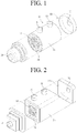
- FIGS. 1 and 2 are views showing a membrane humidifier for a fuel cell according to an embodiment of the present disclosure.
- the membrane humidifier for a fuel cell according to the embodiment of the present disclosure includes a middle case 110, cap cases 120, potting units 130, and assembly members 200.
- the middle case 110 is coupled to the cap cases 120 to define the external appearance of the membrane humidifier.
- Each of the middle case 110 and the cap cases 120 may be made of hard plastic, such as polycarbonate, or metal.
- the lateral sectional shape of each of the middle case 110 and the cap cases 120 may be a circle, as shown in FIG. 1 , or the lateral sectional shape thereof may be a polygon, as shown in FIG. 2 .
- the polygon may be a rectangle, a square, a trapezoid, a parallelogram, a pentagon, or a hexagon, and corners of the polygon may be round.
- the circle may be an oval.
- the middle case 110 is provided with a second fluid inlet 112, through which a second fluid is supplied, and a second fluid outlet 113, through which the second fluid is discharged.
- reference numeral 113 may indicate the second fluid inlet
- reference numeral 112 may indicate the second fluid outlet.
- a hollow fiber membrane module in which a plurality of hollow fiber membranes is housed, is disposed in the middle case 110.
- the hollow fiber membrane module may include a hollow fiber membrane bundle constituted by a plurality of integrated hollow fiber membranes or a plurality of hollow fiber membrane cartridges C, in each of which hollow fiber membranes are housed.
- the drawings illustrate the case in which the hollow fiber membrane module includes hollow fiber membrane cartridges C; however, the case in which the hollow fiber membrane module includes a hollow fiber membrane bundle is not excluded.
- the cap cases 120 are coupled to the respective ends of the middle case 110.
- the cap cases 120 are provided with fluid introduction and discharge ports 121, one of which is a first fluid inlet and the other of which is a first fluid outlet.
- a first fluid introduced through the fluid introduction and discharge port 121 of one of the cap cases 120 passes through an inner pipeline of each of the hollow fiber membranes housed in each of the hollow fiber membrane cartridges C and is then discharged outside through the fluid introduction and discharge port 121 of the other cap case 120.
- Each hollow fiber membrane may be a hollow fiber membrane made of, for example, Nafion, polyetherimide, polyimide (PI), polyphenylsulfone, polysulfone (PS), or polyethersulfone (PES).
- the hollow fiber membrane cartridges C may be provided at one side thereof with a first mesh unit M configured to allow the second fluid introduced into the membrane humidifier through the second fluid inlet 112 to be introduced into the hollow fiber membrane cartridges C therethrough, and may be provided at the other side thereof with a second mesh unit (not shown) configured to allow the second fluid that has performed moisture exchange in the hollow fiber membrane cartridges C to be discharged from the hollow fiber membrane cartridges C therethrough.
- the hollow fiber membrane bundle or the hollow fiber membrane cartridges C are provided at opposite ends thereof with potting units 130 configured to bind the hollow fiber membranes and to fill the gaps between the hollow fiber membranes. As a result, the opposite ends of the hollow fiber membrane module are blocked by the potting units 130, whereby a flow channel configured to allow the second fluid to pass therethrough is defined in the hollow fiber membrane module.
- Each of the potting units 130 is made of a known material, and a detailed description thereof will be omitted from this specification.
- FIG. 3 is a sectional view showing a portion of the membrane humidifier for a fuel cell according to the embodiment of the present disclosure.
- the assembly member 200 includes a first sealing unit 210 and a second sealing unit 220.
- the assembly member 200 is disposed between the potting unit 130 and the end 111 of the middle case 110 in order to simultaneously seal the interior of the middle case 110 and the gap between the middle case 110 and the cap case 120.
- the first sealing unit 210 is made of a soft material, i.e. a material that exhibits low hardness, such as silicone or soft rubber
- the second sealing unit 220 is made of a hard material, i.e. a material that exhibits high hardness, such as plastic, metal, or hard rubber.
- hardness is determined based on ASTM D2240 (Shore A) 70 degrees. That is, a material that has a hardness of 70 degrees or more is a hard material, and a material that has a hardness of less than 70 degrees is a soft material.
- the assembly member 200 may be configured such that the soft first sealing unit 210 wraps the hard second sealing unit 220, and may perform a hermetic sealing function in high-temperature/high-pressure/high-humidity environments through a peculiar mechanical assembly structure.
- the first sealing unit 210 is mounted on the end 111 of the middle case while being in contact with an inner wall 122 of the cap case.
- the second sealing unit 220 is formed inside the first sealing unit 210, and is configured to wrap the potting unit 130.
- the soft first sealing unit 210 presses the inner wall 122 of the cap case while being compressed by the hard second sealing unit 220 to hermetically seal the space defined by the cartridge C and the cap case 120 and the internal space of the middle case 110.
- a coupling protrusion 123 may be formed on the inner wall of the cap case 120, and the coupling protrusion 123 increases the force of fixing between the cap case 120 and the assembly member 200 at the time of assembly of the membrane humidifier.
- the assembly member 200 may be realized as various embodiments depending on the material of the potting unit 130.
- FIG. 4 is a sectional view showing a first embodiment of an assembly member according to an embodiment of the present disclosure
- FIG. 5 is a sectional view showing a second embodiment of the assembly member according to the embodiment of the present disclosure
- FIG. 6 is a sectional view showing a third embodiment of the assembly member according to the embodiment of the present disclosure.
- the assembly member according to the first embodiment is constituted by a first sealing unit 210, which includes a first sealing body 211 and a first sealing leg 212, and a second sealing unit 220, which includes a second sealing body 221 and a sealing arm 222.
- the first sealing body 211 is formed so as to come into contact with the inner wall of the cap case 120 while having a bracket shape, and the first sealing leg 212 is formed so as to come into contact with the second sealing unit 220 while extending downwards from one end of the first sealing body 211 (see FIG. 9 ).
- the first sealing body 211 presses the inner wall 122 of the cap case while being compressed by the second sealing unit 220, and the first sealing leg 212 presses the end 111 of the middle case 110 while being compressed by the second sealing unit 220, to hermetically seal the space defined by the cartridge C and the cap case 120 and the internal space of the middle case 110.
- Each of the second sealing body 221 and the sealing arm 222 is made of a hard material.
- the sealing arm 222 presses the first sealing body 211, and the second sealing body 221 presses the first sealing leg 212.
- the assembly member according to the first embodiment is useful in the case in which the potting unit 130 is made of a soft material.
- the second sealing body 221 is inserted into the soft potting unit 130 while pressing the potting unit 130 inwards during the assembly process of the membrane humidifier.
- the second sealing body 221 and the potting unit 130 are hermetically sealed by restoring force of the potting unit 130 made of a soft material, by which the potting unit returns to the original position thereof.
- the second sealing body 221 presses the first sealing leg 212, and the first sealing leg 212 presses the end 111 of the middle case 110 while being compressed by the second sealing body 221, whereby the space defined by the cartridge C and the cap case 120 and the internal space of the middle case 110 are hermetically sealed (see FIGS. 12 and 13 ).
- the angle ⁇ between the bottom surface and the side surface of the second sealing body 221 is preferably greater than 90 degrees in order to achieve easy assembly between the assembly member and the potting unit 130 and compression of the assembly member.
- the assembly member according to the second embodiment is constituted by a first sealing unit 210, which includes a first sealing body 211, a first sealing leg 212, and a second sealing leg 213, and a second sealing unit 220, which includes a second sealing body 221 and a sealing arm 222.
- first sealing body 211, the first sealing leg 212, the second sealing body 221, and the sealing arm 222 are identical to those of the first embodiment, and a duplicate description thereof will be omitted.
- the first sealing leg 212 extends downwards from one end of the first sealing body 211, and the second sealing leg 213 extends downwards from the other end of the first sealing body 211.
- the end 111 of the middle case 110 is inserted into the gap between the first sealing leg 212 and the second sealing leg 213. At this time, the end 111 of the middle case 110 is provided with a step portion, on which the second sealing leg 213 is fitted (see FIG. 10 ).
- the assembly member according to the second embodiment has an advantage in that the end 111 of the middle case 110 is inserted into the gap between the first sealing leg 212 and the second sealing leg 213, whereby the force of coupling between the assembly member 200 and the middle case 110 is further increased.
- the assembly member according to the third embodiment is constituted by a first sealing unit 210, which includes a first sealing body 211, a first sealing leg 212, a second sealing leg 213, and an extension leg 214, and a second sealing unit 220, which includes a second sealing body 221 and a sealing arm 222.
- first sealing body 211, the first sealing leg 212, the second sealing leg 213, the second sealing body 221, and the sealing arm 222 are identical to those of the second embodiment, and a duplicate description thereof will be omitted.
- the extension leg 214 is made of a soft material, and extends inwards from the end of the first sealing leg 212 and then extends upwards from the end thereof in order to wrap the second sealing unit 220 (specifically, the second sealing body 221) (see FIG. 11 ).
- the assembly member according to the third embodiment is useful in the case in which the potting unit 130 is made of a hard material.
- the soft extension leg 214 is inserted into the hard potting unit 130 while being compressed by the potting unit 130 during the assembly process of the membrane humidifier.
- the assembly member and the potting unit are hermetically sealed by restoring force of the soft extension leg 214, by which the extension leg returns to the original position thereof.
- the second sealing body 221 presses the first sealing leg 212, and the first sealing leg 212 presses the end 111 of the middle case 110 while being compressed by the second sealing body 221, whereby the space defined by the cartridge C and the cap case 120 and the internal space of the middle case 110 are hermetically sealed (see FIGS. 14 and 15 ).
- the angle ⁇ between the bottom surface and the side surface of the second sealing body 221 is preferably greater than 90 degrees in order to achieve easy assembly between the assembly member and the potting unit 130 and compression of the assembly member.
- the assembly member according to each of the first and second embodiments is useful in the case in which the potting unit 130 is made of a soft material, and the assembly member according to the third embodiment is useful in the case in which the potting unit 130 is made of a hard material.
- the assembly member according to each of the first to third embodiments is formed in a circular ring shape or an oval ring shape, and is disposed between the potting unit 130 and the end 111 of the middle case.
- FIGS. 7 and 8 illustrate the assembly member according to the third embodiment, from which the assembly member according to each of the first and second embodiments is easily derived, and therefore an illustration thereof will be omitted.
- FIGS. 16 and 17 are exploded perspective views showing a membrane humidifier for a fuel cell according to another embodiment of the present disclosure.
- the membrane humidifier 100 for a fuel cell according to the other embodiment of the present disclosure includes a middle case 110, cap cases 120, potting units 130, and assembly members 300.
- the middle case 110 is coupled to the cap cases 120 to define the external appearance of the membrane humidifier.
- Each of the middle case 110 and the cap cases 120 may be made of hard plastic, such as polycarbonate, or metal.
- the lateral sectional shape of each of the middle case 110 and the cap cases 120 may be a circle, as shown in FIG. 16 , or the lateral sectional shape thereof may be a polygon, as shown in FIG. 17 .
- the polygon may be a rectangle, a square, a trapezoid, a parallelogram, a pentagon, or a hexagon, and corners of the polygon may be round.
- the circle may be an oval.
- the middle case 110 is provided with a second fluid inlet 112, through which a second fluid is supplied, and a second fluid outlet 113, through which the second fluid is discharged.
- reference numeral 113 may indicate the second fluid inlet
- reference numeral 112 may indicate the second fluid outlet.
- a hollow fiber membrane module in which a plurality of hollow fiber membranes is housed, is disposed in the middle case 110.
- the hollow fiber membrane module may include a hollow fiber membrane bundle constituted by a plurality of integrated hollow fiber membranes or a plurality of hollow fiber membrane cartridges 140 (see FIG. 18 ), in each of which hollow fiber membranes are housed.
- the drawings illustrate the case in which the hollow fiber membrane module includes hollow fiber membrane cartridges 140; however, the case in which the hollow fiber membrane module includes a hollow fiber membrane bundle is not excluded.
- the cap cases 120 are coupled to the respective ends of the middle case 110.
- the cap cases 120 are provided with fluid introduction and discharge ports 121, one of which is a first fluid inlet and the other of which is a first fluid outlet.
- a first fluid introduced through the fluid introduction and discharge port 121 of one of the cap cases 120 passes through an inner pipeline of each of the hollow fiber membranes housed in each of the hollow fiber membrane cartridges 140 and is then discharged outside through the fluid introduction and discharge port 121 of the other cap case 120.
- Each hollow fiber membrane may be a hollow fiber membrane made of, for example, Nafion, polyetherimide, polyimide (PI), polyphenylsulfone, polysulfone (PS), or polyethersulfone (PES).
- the hollow fiber membrane cartridges C may be provided at one side thereof with a first mesh unit 142 configured to allow the second fluid introduced into the membrane humidifier through the second fluid inlet 112 to be introduced into the hollow fiber membrane cartridges 140 therethrough, and may be provided at the other side thereof with a second mesh unit (not shown) configured to allow the second fluid that has performed moisture exchange in the hollow fiber membrane cartridges 140 to be discharged from the hollow fiber membrane cartridges 140 therethrough.
- the hollow fiber membrane bundle or the hollow fiber membrane cartridges 140 are provided at both ends thereof with potting units 130 configured to bind the hollow fiber membranes and to fill the gaps between the hollow fiber membranes. As a result, the both ends of the hollow fiber membrane module are blocked by the potting units 130, whereby a flow channel configured to allow the second fluid to pass therethrough is defined in the hollow fiber membrane module.
- Each of the potting units 130 is made of a known material, and a detailed description thereof will be omitted from this specification.
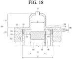
- FIG. 18 is a sectional view showing a membrane humidifier according to a fourth embodiment of the present disclosure
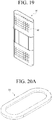
- FIG. 9 is a perspective view showing a hollow fiber membrane cartridge according to an embodiment of the present disclosure
- FIG. 70 is a perspective view showing an assembly member according to an embodiment of the present disclosure.
- the hollow fiber membrane module includes a hollow fiber membrane cartridge 140
- a hollow fiber membrane cartridge 140 is shown in the drawings; however, the case in which a plurality of hollow fiber membrane cartridges 140 is included in the membrane humidifier is not excluded.
- the hollow fiber membrane cartridge 140 of FIG. 19 is one of a plurality of cartridges disposed in the case of the membrane humidifier.
- FIG. 20 shows an assembly member in the case in which a single cartridge and a potting unit are provided, and the shown assembly member 300 is configured so as to have a structure in which a pair of linear portions facing each other and a pair of semicircular portions facing each other are connected to each other.
- FIG. 20A is a perspective view when viewed from the side at which the assembly member contacts the cap case 120
- FIG. 20B is a perspective view when viewed from the opposite side.
- the assembly member 300 is disposed between the end of the middle case 110 and the cap case 120. At the same time, the assembly member 300 may also be disposed between the cap case 120 and the potting unit 130.
- the inner surface of the cap case 120 is assembled so as to be spaced apart from the end 111 of the middle case 110.
- the inner surface of the cap case 120 is also assembled so as to be spaced apart from the potting unit 130.
- the assembly member 300 is assembled so as to hermetically seal the gap between the cap case 120 and the middle case 110 and the gap between the cap case 120 and the potting unit 130.
- the middle case 110 and the cap case 120 are assembled using various fastening methods (not shown), such as fastening using a plurality of bolts, pressing, welding, and clamping. At this time, assembly is performed such that the assembly member 300 is inserted into the gap between the middle case and the cap case and is then pressed.
- FIG. 18 and the following figures are sectional views taken along planes that do not pass through fastening units, such as bolts, and therefore fastening units, such as bolts, are not shown.
- each of the middle case 110 and the cap case 120 may have a polygonal or circular section.
- the sectional views of FIG. 18 and the following figures show the case in which each of the middle case 110 and the cap case 120 has a quadrangular section.
- the cap case 120 may include a large-diameter portion 125 coupled to the middle case 110, the large-diameter portion having an inner diameter L1 greater than the outer diameter L3 of the potting unit 130, and a small-diameter portion 127 protruding from one surface of the large-diameter portion 125, the small-diameter portion having an inner diameter L2 less than the outer diameter L3 of the potting unit 130.
- the outer diameter, the inner diameter, the large-diameter portion, and the small-diameter portion are generally terms related to the diameter of a circular pipe; however, the cases in which a housing of the membrane humidifier is circular, oval, and polygonal are all included.
- the distance L2 between opposite inner surfaces of the small-diameter portion 127 of the cap case 120, in which the fluid introduction and discharge port 121 is formed, is less than the distance L3 between opposite outer surfaces of the potting unit 130. Consequently, the assembly member 300 may be pressed between the cap case 120 and the potting unit 130 at the time of assembly.
- the shape of the cap case 120 may be applied to all of the following embodiments as well as the fourth embodiment without change.
- the distance L3 between opposite outer surfaces of the potting unit 130 is less than the distance between opposite inner surfaces of the middle case 110, whereby the potting unit 130 is disposed in the middle case 110 so as to be spaced apart therefrom. Consequently, the assembly member 300 is disposed between the middle case 110 and the potting unit 130 to fix the potting unit 130 such that the potting unit cannot move relative to the middle case 110.
- the assembly member 300 is assembled so as to simultaneously perform hermetic coupling between the middle case 110 and the cap case 120, between the cap case 120 and the potting unit 130, and between the middle case 110 and the potting unit 130.
- the assembly member 300 includes a main body 310 disposed between the cap case 120, the middle case 110, and the potting unit 130, a first coupling portion 320 pressed between the cap case 120 and the end of the middle case 110 in order to perform hermetic coupling between the cap case 120 and the middle case 110, and a second coupling portion 330 brought into contact with one end of the potting unit 130 in order to perform hermetic coupling between the cap case 120 and the potting unit 130.
- a pair of assembly members 300 is shown as being disposed in a horizontally symmetrical fashion in the sectional view of FIG. 18 ; however, it should be understood that, in actuality, a single assembly member 300 is generally formed so as to have a quadrangular ring shape.
- the main body 310 is disposed on the inner surface of the cap case 120, the inner surface of the middle case 110, and the upper surface of the potting unit 130 in tight contact therewith.
- the first coupling portion 320 is inserted and pressed into the gap between the cap case 120 and the end of the middle case 110.
- the first coupling portion 320 may include a first extension portion 322 extending outwards from the main body 310 and a second extension portion 324 extending from the end of the extending portion so as to come into contact with the outer surface of the middle case 110. Consequently, a recess, into which the end of the middle case 110 is inserted, may be formed between the outer surface of the main body 310 and the inner surface of the second extension portion 324.
- outer surface of the second extension portion 324 may be in contact with the inner surface of the cap case 120, although not in contact with the inner surface of the cap case, as shown.
- a step portion 115 configured to receive the second extension portion 324 of the first coupling portion 320 may be provided at the outer surface of the end 111 of the middle case 110. As a result, the outer surface of the middle case 110 and the outer surface of the second extension portion 324 may form almost the same plane.
- the second coupling portion 330 is a portion at which the inner edge of the assembly member 300 is pressed against the edge of the potting unit 130.
- the relative hardness of the assembly member 300 and the potting unit 130 may be variously configured. In the case in which the hardness of the assembly member 300 is less than the hardness of the potting unit 130, the second coupling portion 330 of the assembly member 300 is pressed and contracted by the potting unit 130 at the time of assembly. FIG. 18 shows this case.
- the edge of the potting unit 130 may be pressed and contracted by the second coupling portion 330 of the assembly member 300 at the time of assembly.
- the region of the second coupling portion 330 indicated by a dotted line shows the external appearance of the second coupling portion before being pressed by the potting unit 130.
- the pressed regions of the assembly member 300 and the potting unit 130 may be simultaneously contracted at the time of assembly.
- the cap case 120 includes a protrusion 123 protruding from a surface thereof, the surface facing the end 111 of the middle case 110.
- the protrusion 123 may be formed in the shape of a rib having a semicircular section or any of various other shapes.
- the protrusion 123 serves to further press the first coupling portion 320 of the assembly member 300, thereby improving hermetic sealing, and to fix the first coupling portion 320 such that the first coupling portion cannot move when pressed.
- the protrusion 123 of the cap case 120 may be formed at the position facing the end of the middle case 110, or may also be formed at the position facing the border of the potting unit 130. In addition, a protrusion may be formed between the two protrusions.
- a protrusion 116 formed in the shape of a rib having a semicircular section may also be provided at the end 111 of the middle case 110.
- the protrusion 116 of the middle case 110 and the protrusion 123 of the cap case 120 may be disposed so as to be staggered from each other, rather than facing each other. In the case in which the two protrusions are disposed so as to be staggered from each other, hermetic sealing may be further improved when the assembly member 300 is pressed.
- FIG. 21 is a sectional view showing a membrane humidifier according to a fifth embodiment of the present disclosure.
- the membrane humidifier according to the fifth embodiment is different from the membrane humidifier according to the fourth embodiment in that the cartridge 140 includes an extension rib 145 configured to support one surface of the assembly member 300.
- a plurality of hollow fiber membranes are housed in a cartridge 140, and the cartridge or a plurality of cartridges is disposed in the middle case 110.
- the extension rib 145 extends outwards from the upper end of the cartridge 140 so as to support the lower surface of the assembly member 300.
- the extension rib 145 may be formed so as to press and support a portion or the entirety of the lower surface of the main body 310 of the assembly member 300.
- the extension rib 145 may be configured in the shape of a quadrangular ring having a predetermined width.
- the extension rib 145 may be configured in the shape of a circular ring having a predetermined width.
- the first coupling portion 320 is pressed by the end 111 of the middle case 110, and the second coupling portion 330 is pressed by the potting unit 130.
- the main body 310 of the assembly member 300 is also pressed against the cap case 120 by the extension rib 145, whereby the entirety of the assembly member 300 is uniformly pressed, and therefore hermetic sealing is further improved.
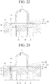
- FIG. 22 is a sectional view showing a membrane humidifier according to a sixth embodiment of the present disclosure.
- the membrane humidifier according to the sixth embodiment is different from the membrane humidifier according to the fourth embodiment in that the first coupling portion 320 includes no second extension portion.
- the first coupling portion 320 of the assembly member 300 includes a first extension portion 322 extending outwards from the main body 310 but does not include a second extension portion extending from the end of the first extension portion 322 so as to come into contact with the outer surface of the middle case.
- FIG. 23 is a sectional view showing a membrane humidifier according to a seventh embodiment of the present disclosure.
- the membrane humidifier according to the seventh embodiment is different from the membrane humidifier according to the fourth embodiment in that inclined surfaces are formed on the edges of the second coupling portion 330 of the assembly member 300 and the potting unit 130 so as to come into contact with each other.
- An inclined portion 322 is formed at the second coupling portion 330, and an inclined portion 132 is also formed at the edge of the upper end of the potting unit 130.
- the hardness of the assembly member 300 is greater than the hardness of the potting unit 130, and therefore the inclined portion 322 of the second coupling portion 330 presses the inclined portion 132 of the potting unit 130 at the time of assembly.
- the inclined portion 132 of the potting unit 130 presses the inclined portion 322 of the second coupling portion 330 at the time of assembly.
- hermetic sealing performance may be further improved compared to the other embodiments.
- the inclined portion 322 of the second coupling portion 330 and the inclined portion 132 of the potting unit 130 may be formed, although both may be simultaneously formed.
- the inclined portion may be formed at any one of the assembly member 300 and the potting unit 130 that has higher hardness, and the other that has lower hardness may be pressed by the inclined portion and thus may be deformed so as to have an inclined surface.
- FIG. 24 is a sectional view showing a membrane humidifier according to an eighth embodiment of the present disclosure.
- the membrane humidifier according to the eighth embodiment is different from the membrane humidifier according to the fourth embodiment in that the assembly member 300 further includes a rib 335 extending toward the potting unit 130.
- a rib 335 extending inwards so as to come into tight contact with one side surface of the potting unit 130 is formed at the second coupling portion 330 of the assembly member 300.
- the sectional shape of the rib 335 may be a triangular shape, the thickness of which gradually decreases toward the end thereof.
- the membrane humidifier When the membrane humidifier is assembled, pressure higher than atmospheric pressure is generally applied to a space defined by the cap case 120, the assembly member 300, and the potting unit 130, although the value of pressure varies depending on the use conditions of a fuel cell system.
- the rib 335 may be brought into tight contact with one side surface of the potting unit 130 by the pressure, whereby it is possible to more securely achieve hermetic coupling therebetween.
- the assembly member 300 of the eighth embodiment may have higher hardness than the assembly member 300 of the fourth embodiment. In other words, hermetic sealing between the assembly member 300 of the eighth embodiment and the potting unit 130 may be further improved due to the rib 335 although the assembly member is not greatly deformed when pressed at the time of assembly.
- FIG. 24 shows the state after assembly.
- the lower surface of the rib 335 may be formed so as to be parallel to the contact surface of the potting unit 130, or may be formed so as to be inclined at a predetermined angle to the contact surface of the potting unit 130. In the case in which the rib 335 is formed so as to be inclined, the rib 335 may be deformed by the potting unit at the time of assembly, whereby the rib may be brought into tighter contact with the potting unit 130.
- FIG. 25 is a sectional view showing a membrane humidifier according to a ninth embodiment of the present disclosure.
- the membrane humidifier according to the ninth embodiment is different from the membrane humidifier according to the eighth embodiment in that the first coupling portion 320 includes no second extension portion.
- the membrane humidifier according to the ninth embodiment is identical to the membrane humidifier according to the eighth embodiment in that the assembly member 300 further includes a rib 335 extending parallel with one side surface of the potting unit 130.
- the assembly member 300 includes a rib 335, whereby the difference in hardness between the assembly member 300 and the potting unit 130 may be less than the difference in hardness therebetween in the case of the eighth embodiment.
- hermetic sealing between the assembly member 300 of the ninth embodiment and the potting unit 130 may be further improved due to the rib 335 although the assembly member is not greatly deformed when pressed at the time of assembly.
- the first coupling portion 320 of the assembly member 300 includes a first extension portion 322 extending outwards from the main body 310 but does not include a second extension portion extending from the end of the first extension portion 322 so as to come into contact with the outer surface of the middle case.
- a membrane humidifier for a fuel cell including an assembly member according to each of various embodiments of the present disclosure is capable of performing a hermetic sealing function in high-temperature/highpressure/high-humidity environments through a mechanical assembly structure.
- a mechanical sealing method is used instead of a chemical sealing method, whereby it is possible to omit a polyurethane/sealant coating and curing process necessary in a conventional chemical sealing method, and therefore it is possible to shorten working time, to improve work efficiency, and to construct a mass production system.
- the membrane humidifier may be disassembled, only defective cartridges may be replaced, and then the membrane humidifier may be reassembled, whereby the present disclosure is advantageous in terms of reworkability and reuse of parts.
Landscapes
- Chemical & Material Sciences (AREA)
- Chemical Kinetics & Catalysis (AREA)
- Life Sciences & Earth Sciences (AREA)
- Engineering & Computer Science (AREA)
- Manufacturing & Machinery (AREA)
- Sustainable Development (AREA)
- Sustainable Energy (AREA)
- Electrochemistry (AREA)
- General Chemical & Material Sciences (AREA)
- Fuel Cell (AREA)
- Separation Using Semi-Permeable Membranes (AREA)
Abstract
Description
- The present disclosure relates to a membrane humidifier for a fuel cell, and more particularly to a membrane humidifier for a fuel cell capable of performing a hermetic sealing function in high-temperature/highpressure/high-humidity environments through a mechanical assembly structure.
- A fuel cell is a power generation cell that combines hydrogen and oxygen to generate electricity. Such a fuel cell has advantages in that it is possible to continuously generate electricity as long as hydrogen and oxygen are supplied, unlike a general chemical cell, such as a dry cell or a storage cell, and in that there is no heat loss, whereby efficiency of the fuel cell is about twice as high as efficiency of an internal combustion engine.
- In addition, the fuel cell directly converts chemical energy generated by combination of hydrogen and oxygen into electrical energy, whereby the amount of contaminants that are discharged is small. Consequently, the fuel cell has advantages in that the fuel cell is environmentally friendly and in that a concern about depletion of resources due to an increase in energy consumption can be reduced.
- Based on the kind of an electrolyte that is used, such a fuel cell may be classified as a polymer electrolyte membrane fuel cell (PEMFC), a phosphoric acid fuel cell (PAFC), a molten carbonate fuel cell (MCFC), a solid oxide fuel cell (SOFC), or an alkaline fuel cell (AFC).
- These fuel cells are operated fundamentally by the same principle, but are different from each other in terms of the kind of fuel that is used, operating temperature, catalyst, and electrolyte. Among these fuel cells, the polymer electrolyte membrane fuel cell (PEMFC) is known as being the most favorable to a transportation system as well as small-scale stationary power generation equipment, since the polymer electrolyte membrane fuel cell is operated at a lower temperature than the other fuel cells and the output density of the polymer electrolyte membrane fuel cell is high, whereby it is possible to miniaturize the polymer electrolyte membrane fuel cell.
- One of the most important factors that improve the performance of the polymer electrolyte membrane fuel cell (PEMFC) is to supply a predetermined amount or more of moisture to a polymer electrolyte membrane or a proton exchange membrane (PEM) of a membrane electrode assembly (MEA) in order to retain water content. The reason for this is that, in the case in which the polymer electrolyte membrane or the proton exchange membrane is dried, power generation efficiency is abruptly reduced.
- 1) A bubbler humidification method of filling a pressure-resistant container with water and allowing a target gas to pass through a diffuser in order to supply moisture, 2) a direct injection method of calculating the amount of moisture to be supplied that is necessary for fuel cell reaction and directly supplying moisture to a gas flowing pipe through a solenoid valve, and 3) a humidification membrane method of supplying moisture to a gas flowing layer using a polymer separation membrane are used as methods of humidifying the polymer electrolyte membrane or the proton exchange membrane.
- Among these methods, the humidification membrane method, which provides water vapor to a gas that is supplied to the polymer electrolyte membrane or the proton exchange membrane using a membrane configured to selectively transmit only water vapor included in an exhaust gas in order to humidify the polymer electrolyte membrane or the proton exchange membrane, is advantageous in that it is possible to reduce the weight and size of a humidifier.
- In the case in which a module is formed, a hollow fiber membrane having large transmission area per unit volume is preferably used as the selective transmission membrane used in the humidification membrane method. That is, in the case in which a membrane humidifier is manufactured using a hollow fiber membrane, high integration of the hollow fiber membrane having large contact surface area is possible, whereby it is possible to sufficiently humidify a fuel cell even in the case of a small capacity, it is possible to use a low-priced material, and it is possible to collect moisture and heat included in a non-reaction gas discharged from the fuel cell at a high temperature and to reuse the collected moisture and heat through the humidifier.
- Meanwhile, in a general membrane humidifier for a fuel cell, hollow fiber membranes are received in a housing unit, and the hollow fiber membranes are adhered to the inner wall of the housing unit by a potting unit. A specific number of hollow fiber membranes are received based on a desired output value of a stack, and the hollow fiber membranes are adhered and fixed to the housing unit by the potting unit. High-temperature air from a blower and high-temperature and high-humidity air from the stack are introduced into the membrane humidifier for a fuel cell. The coefficient of thermal expansion and the coefficient of thermal shrinkage of the potting unit are high, whereby a gap is formed between the housing unit and the potting unit and air leaks therethrough. In order to prevent this, a sealant is coated in the gap between the housing unit and the potting unit.
- In a case of air leakage, the air introduced from the blower leaks from the membrane humidifier for a fuel cell, whereby the amount of air that is introduced into the stack is reduced. For this reason, it is necessary for the blower to supply a larger amount of air than the amount of air actually necessary for the stack, whereby the power consumption of the blower is increased, which leads to system power loss. Consequently, maximum leakage prevention is advantageous in terms of overall power efficiency.
- It is an object of the present disclosure to provide a membrane humidifier for a fuel cell capable of performing a hermetic sealing function in high-temperature/high-pressure/high-humidity environments through a mechanical assembly structure.
- A membrane humidifier for a fuel cell according to an embodiment of the present disclosure includes a middle case housing a plurality of hollow fiber membranes, a cap case coupled to the middle case, a potting unit formed at ends of the plurality of hollow fiber membranes, and an assembly member disposed between the cap case and the end of the middle case, the assembly member being configured to simultaneously perform hermetic coupling between the cap case and the middle case and between the cap case and the potting unit.
- The assembly member may include a first sealing unit mounted on the end of the middle case while being in contact with the inner wall of the cap case and a second sealing unit formed inside the first sealing unit so as to wrap the potting unit.
- The first sealing unit may include a first sealing body mounted on the end of the middle case while being in contact with the inner wall of the cap case, the first sealing body being formed so as to have a bracket shape, and a first sealing leg formed so as to come into contact with the second sealing unit while extending downwards from one end of the first sealing body.
- The first sealing unit may further include an extension leg extending inwards from the end of the first sealing leg and then extending upwards from the end thereof such that the extension leg wraps the second sealing unit.
- The first sealing unit may further include a second sealing leg extending downwards from the other end of the first sealing body, the second sealing leg being in contact with the inner wall of the cap case and the end of the middle case.
- The first sealing unit may further include a second sealing leg extending downwards from the other end of the first sealing body, the second sealing leg being in contact with the inner wall of the cap case and the end of the middle case.
- The second sealing unit may include a second sealing body formed so as to wrap the potting unit and a sealing arm inserted into the first sealing body.
- The first sealing unit may be made of a soft material, and the second sealing unit may be made of a hard material.
- A membrane humidifier for a fuel cell according to another embodiment of the present disclosure may include a middle case housing a plurality of hollow fiber membranes, a cap case coupled to the middle case, a potting unit formed at ends of the plurality of hollow fiber membranes, and an assembly member disposed between the cap case and the end of the middle case, the assembly member being configured to simultaneously perform hermetic coupling between the cap case and the middle case and between the cap case and the potting unit.
- The cap case may include a large-diameter portion coupled to the middle case, the large-diameter portion having an inner diameter greater than the outer diameter of the potting unit, and a small-diameter portion protruding from one surface of the large-diameter portion, the small-diameter portion having an inner diameter less than the outer diameter of the potting unit.
- The assembly member may include a main body disposed between the cap case, the middle case, and the potting unit, a first coupling portion pressed between the cap case and the end of the middle case in order to perform hermetic coupling between the cap case and the middle case, and a second coupling portion brought into contact with one end of the potting unit in order to perform hermetic coupling between the cap case and the potting unit.
- The first coupling portion may include a first extension portion extending outwards from the main body.
- The first coupling portion may further include a second extension portion extending from the end of the first extension portion so as to come into contact with an outer surface of the middle case.
- A step portion configured to receive the second extension portion of the first coupling portion may be provided at the outer surface of the end of the middle case.
- The cap case may include a protrusion protruding from the surface thereof, the surface facing the end of the middle case.
- The second coupling portion of the assembly member may include an inclined portion formed at the inner surface thereof, and the potting unit may include an inclined portion formed at the end edge thereof, the inclined portion of the potting unit being in contact with the inclined portion of the second coupling portion.
- The hardness of the assembly member may be less than the hardness of the potting unit.
- The plurality of hollow fiber membranes may be housed in a cartridge, and the cartridge may include an extension rib extending outwards from one end thereof, the extension rib being configured to support one surface of the assembly member.
- The assembly member may further include a rib extending inwards so as to widen the surface area thereof that contacts the potting unit.
- The hardness of the assembly member may be greater than the hardness of the potting unit and may be less than the hardness of the middle case and the hardness of the cap case.
- A membrane humidifier for a fuel cell according to the present disclosure is capable of performing a hermetic sealing function in high-temperature/high-pressure/high-humidity environments through a mechanical assembly structure.
- In addition, a mechanical sealing method is used instead of a chemical sealing method, whereby it is possible to omit a polyurethane/sealant coating and curing process necessary for a conventional chemical sealing method, and therefore it is possible to shorten working time, to improve work efficiency, and to construct a mass production system.
- In addition, when unit cartridges disposed in the membrane humidifier are defective, reworkability is excellent, whereby it is possible to reduce a part scrap rate.
- In addition, the membrane humidifier may be disassembled, only defective cartridges may be replaced, and then the membrane humidifier may be reassembled, whereby the present disclosure is advantageous in terms of reworkability and reuse of parts.
- Furthermore, it is possible to simultaneously perform hermetic coupling between two or more parts using two separable assembly members or a single integrated assembly member, whereby manufacture and assembly are very convenient and efficient.
-
-
FIGS. 1 and 2 are views showing a membrane humidifier for a fuel cell according to an embodiment of the present disclosure. -
FIG. 3 is a sectional view showing a portion of the membrane humidifier for a fuel cell according to the embodiment of the present disclosure. -
FIG. 4 is a sectional view showing a first embodiment of an assembly member according to the present disclosure. -
FIG. 5 is a sectional view showing a second embodiment of the assembly member according to the present disclosure. -
FIG. 6 is a sectional view showing a third embodiment of the assembly member according to the present disclosure. -
FIG. 7 is a perspective view showing the third embodiment of the assembly member according to the present disclosure. -
FIG. 8 is an exploded perspective view showing the third embodiment of the assembly member according to the present disclosure. -
FIG. 9 is a partial enlarged view showing the state in which the assembly member ofFIG. 4 seals the membrane humidifier for a fuel cell. -
FIG. 10 is a partial enlarged view showing the state in which the assembly member ofFIG. 5 seals the membrane humidifier for a fuel cell. -
FIG. 11 is a partial enlarged view showing the state in which the assembly member ofFIG. 6 seals the membrane humidifier for a fuel cell. -
FIG. 12 is a partial enlarged view showing the process in which the assembly member ofFIG. 5 is inserted into a potting unit. -
FIG. 13 is a partial enlarged view showing the state in which the assembly member ofFIG. 5 is inserted in the potting unit. -
FIG. 14 is a partial enlarged view showing the process in which the assembly member ofFIG. 6 is inserted into the potting unit. -
FIG. 15 is a partial enlarged view showing the state in which the assembly member ofFIG. 6 is inserted into the potting unit. -
FIGS. 16 and 17 are exploded perspective views showing a membrane humidifier for a fuel cell according to an embodiment of the present disclosure. -
FIG. 18 is a sectional view showing a membrane humidifier according to a fourth embodiment of the present disclosure. -
FIG. 19 is a perspective view showing a hollow fiber membrane cartridge according to an embodiment of the present disclosure. -
FIG. 20 is a perspective view showing an assembly member according to an embodiment of the present disclosure. -
FIG. 21 is a sectional view showing a membrane humidifier according to a fifth embodiment of the present disclosure. -
FIG. 22 is a sectional view showing a membrane humidifier according to a sixth embodiment of the present disclosure. -
FIG. 23 is a sectional view showing a membrane humidifier according to a seventh embodiment of the present disclosure. -
FIG. 24 is a sectional view showing a membrane humidifier according to an eighth embodiment of the present disclosure. -
FIG. 25 is a sectional view showing a membrane humidifier according to a ninth embodiment of the present disclosure. - The present disclosure may be changed in various manners and may have various embodiments, wherein specific embodiments will be illustrated and described in detail in the following detailed description. However, the present disclosure is not limited to the specific embodiments, and it should be understood that the present disclosure includes all modifications, equivalents, or substitutions included in the idea and technical scope of the present disclosure.
- The terms used in the present disclosure are provided only to describe the specific embodiments, and do not limit the present disclosure. Singular forms are intended to include plural forms as well, unless the context clearly indicates otherwise. In the present disclosure, it should be understood that the terms "includes," "has," etc. specify the presence of features, numbers, steps, operations, elements, components, or combinations thereof described in the specification, but do not preclude the presence or addition of one or more other features, numbers, steps, operations, elements, components, or combinations thereof.
- Hereinafter, a membrane humidifier for a fuel cell according to an embodiment of the present disclosure will be described with reference to the accompanying drawings.
-
FIGS. 1 and 2 are views showing a membrane humidifier for a fuel cell according to an embodiment of the present disclosure. As shown inFIGS. 1 and 2 , the membrane humidifier for a fuel cell according to the embodiment of the present disclosure includes amiddle case 110,cap cases 120,potting units 130, andassembly members 200. - The
middle case 110 is coupled to thecap cases 120 to define the external appearance of the membrane humidifier. Each of themiddle case 110 and thecap cases 120 may be made of hard plastic, such as polycarbonate, or metal. The lateral sectional shape of each of themiddle case 110 and thecap cases 120 may be a circle, as shown inFIG. 1 , or the lateral sectional shape thereof may be a polygon, as shown inFIG. 2 . The polygon may be a rectangle, a square, a trapezoid, a parallelogram, a pentagon, or a hexagon, and corners of the polygon may be round. In addition, the circle may be an oval. Themiddle case 110 is provided with a secondfluid inlet 112, through which a second fluid is supplied, and a secondfluid outlet 113, through which the second fluid is discharged. Alternatively,reference numeral 113 may indicate the second fluid inlet, andreference numeral 112 may indicate the second fluid outlet. - A hollow fiber membrane module, in which a plurality of hollow fiber membranes is housed, is disposed in the
middle case 110. The hollow fiber membrane module may include a hollow fiber membrane bundle constituted by a plurality of integrated hollow fiber membranes or a plurality of hollow fiber membrane cartridges C, in each of which hollow fiber membranes are housed. The drawings illustrate the case in which the hollow fiber membrane module includes hollow fiber membrane cartridges C; however, the case in which the hollow fiber membrane module includes a hollow fiber membrane bundle is not excluded. - The
cap cases 120 are coupled to the respective ends of themiddle case 110. Thecap cases 120 are provided with fluid introduction and dischargeports 121, one of which is a first fluid inlet and the other of which is a first fluid outlet. A first fluid introduced through the fluid introduction and dischargeport 121 of one of thecap cases 120 passes through an inner pipeline of each of the hollow fiber membranes housed in each of the hollow fiber membrane cartridges C and is then discharged outside through the fluid introduction and dischargeport 121 of theother cap case 120. Each hollow fiber membrane may be a hollow fiber membrane made of, for example, Nafion, polyetherimide, polyimide (PI), polyphenylsulfone, polysulfone (PS), or polyethersulfone (PES). - In the case in which the hollow fiber membrane module includes a plurality of hollow fiber membrane cartridges C, the hollow fiber membrane cartridges C may be provided at one side thereof with a first mesh unit M configured to allow the second fluid introduced into the membrane humidifier through the second
fluid inlet 112 to be introduced into the hollow fiber membrane cartridges C therethrough, and may be provided at the other side thereof with a second mesh unit (not shown) configured to allow the second fluid that has performed moisture exchange in the hollow fiber membrane cartridges C to be discharged from the hollow fiber membrane cartridges C therethrough. - The hollow fiber membrane bundle or the hollow fiber membrane cartridges C are provided at opposite ends thereof with
potting units 130 configured to bind the hollow fiber membranes and to fill the gaps between the hollow fiber membranes. As a result, the opposite ends of the hollow fiber membrane module are blocked by thepotting units 130, whereby a flow channel configured to allow the second fluid to pass therethrough is defined in the hollow fiber membrane module. Each of thepotting units 130 is made of a known material, and a detailed description thereof will be omitted from this specification. -
FIG. 3 is a sectional view showing a portion of the membrane humidifier for a fuel cell according to the embodiment of the present disclosure. As shown inFIG. 3 , theassembly member 200 includes afirst sealing unit 210 and asecond sealing unit 220. Theassembly member 200 is disposed between thepotting unit 130 and theend 111 of themiddle case 110 in order to simultaneously seal the interior of themiddle case 110 and the gap between themiddle case 110 and thecap case 120. - The
first sealing unit 210 is made of a soft material, i.e. a material that exhibits low hardness, such as silicone or soft rubber, and thesecond sealing unit 220 is made of a hard material, i.e. a material that exhibits high hardness, such as plastic, metal, or hard rubber. Here, hardness is determined based on ASTM D2240 (Shore A) 70 degrees. That is, a material that has a hardness of 70 degrees or more is a hard material, and a material that has a hardness of less than 70 degrees is a soft material. - The
assembly member 200 may be configured such that the softfirst sealing unit 210 wraps the hard second sealingunit 220, and may perform a hermetic sealing function in high-temperature/high-pressure/high-humidity environments through a peculiar mechanical assembly structure. - The
first sealing unit 210 is mounted on theend 111 of the middle case while being in contact with aninner wall 122 of the cap case. Thesecond sealing unit 220 is formed inside thefirst sealing unit 210, and is configured to wrap thepotting unit 130. - During an assembly process, the soft
first sealing unit 210 presses theinner wall 122 of the cap case while being compressed by the hard second sealingunit 220 to hermetically seal the space defined by the cartridge C and thecap case 120 and the internal space of themiddle case 110. In some embodiments, acoupling protrusion 123 may be formed on the inner wall of thecap case 120, and thecoupling protrusion 123 increases the force of fixing between thecap case 120 and theassembly member 200 at the time of assembly of the membrane humidifier. - The
assembly member 200 may be realized as various embodiments depending on the material of thepotting unit 130. - Hereinafter, various shapes of the
assembly member 200 will be described with reference toFIGS. 4 to 6 .FIG. 4 is a sectional view showing a first embodiment of an assembly member according to an embodiment of the present disclosure,FIG. 5 is a sectional view showing a second embodiment of the assembly member according to the embodiment of the present disclosure, andFIG. 6 is a sectional view showing a third embodiment of the assembly member according to the embodiment of the present disclosure. - As shown in
FIG. 4 , the assembly member according to the first embodiment is constituted by afirst sealing unit 210, which includes afirst sealing body 211 and afirst sealing leg 212, and asecond sealing unit 220, which includes asecond sealing body 221 and asealing arm 222. - The
first sealing body 211 is formed so as to come into contact with the inner wall of thecap case 120 while having a bracket shape, and thefirst sealing leg 212 is formed so as to come into contact with thesecond sealing unit 220 while extending downwards from one end of the first sealing body 211 (seeFIG. 9 ). - During the assembly process of the membrane humidifier, the
first sealing body 211 presses theinner wall 122 of the cap case while being compressed by thesecond sealing unit 220, and thefirst sealing leg 212 presses theend 111 of themiddle case 110 while being compressed by thesecond sealing unit 220, to hermetically seal the space defined by the cartridge C and thecap case 120 and the internal space of themiddle case 110. - Each of the
second sealing body 221 and the sealingarm 222 is made of a hard material. The sealingarm 222 presses thefirst sealing body 211, and thesecond sealing body 221 presses thefirst sealing leg 212. - The assembly member according to the first embodiment is useful in the case in which the
potting unit 130 is made of a soft material. In the assembly member according to the first embodiment, thesecond sealing body 221 is inserted into thesoft potting unit 130 while pressing thepotting unit 130 inwards during the assembly process of the membrane humidifier. Thesecond sealing body 221 and thepotting unit 130 are hermetically sealed by restoring force of thepotting unit 130 made of a soft material, by which the potting unit returns to the original position thereof. At the same time, thesecond sealing body 221 presses thefirst sealing leg 212, and thefirst sealing leg 212 presses theend 111 of themiddle case 110 while being compressed by thesecond sealing body 221, whereby the space defined by the cartridge C and thecap case 120 and the internal space of themiddle case 110 are hermetically sealed (seeFIGS. 12 and13 ). At this time, the angle θ between the bottom surface and the side surface of thesecond sealing body 221 is preferably greater than 90 degrees in order to achieve easy assembly between the assembly member and thepotting unit 130 and compression of the assembly member. - As shown in
FIG. 5 , the assembly member according to the second embodiment is constituted by afirst sealing unit 210, which includes afirst sealing body 211, afirst sealing leg 212, and asecond sealing leg 213, and asecond sealing unit 220, which includes asecond sealing body 221 and asealing arm 222. Here, thefirst sealing body 211, thefirst sealing leg 212, thesecond sealing body 221, and the sealingarm 222 are identical to those of the first embodiment, and a duplicate description thereof will be omitted. - The
first sealing leg 212 extends downwards from one end of thefirst sealing body 211, and thesecond sealing leg 213 extends downwards from the other end of thefirst sealing body 211. Theend 111 of themiddle case 110 is inserted into the gap between thefirst sealing leg 212 and thesecond sealing leg 213. At this time, theend 111 of themiddle case 110 is provided with a step portion, on which thesecond sealing leg 213 is fitted (seeFIG. 10 ). - The assembly member according to the second embodiment has an advantage in that the
end 111 of themiddle case 110 is inserted into the gap between thefirst sealing leg 212 and thesecond sealing leg 213, whereby the force of coupling between theassembly member 200 and themiddle case 110 is further increased. - As shown in
FIG. 6 , the assembly member according to the third embodiment is constituted by afirst sealing unit 210, which includes afirst sealing body 211, afirst sealing leg 212, asecond sealing leg 213, and anextension leg 214, and asecond sealing unit 220, which includes asecond sealing body 221 and asealing arm 222. Here, thefirst sealing body 211, thefirst sealing leg 212, thesecond sealing leg 213, thesecond sealing body 221, and the sealingarm 222 are identical to those of the second embodiment, and a duplicate description thereof will be omitted. - The
extension leg 214 is made of a soft material, and extends inwards from the end of thefirst sealing leg 212 and then extends upwards from the end thereof in order to wrap the second sealing unit 220 (specifically, the second sealing body 221) (seeFIG. 11 ). - The assembly member according to the third embodiment is useful in the case in which the
potting unit 130 is made of a hard material. In the assembly member according to the third embodiment, thesoft extension leg 214 is inserted into thehard potting unit 130 while being compressed by thepotting unit 130 during the assembly process of the membrane humidifier. The assembly member and the potting unit are hermetically sealed by restoring force of thesoft extension leg 214, by which the extension leg returns to the original position thereof. At the same time, thesecond sealing body 221 presses thefirst sealing leg 212, and thefirst sealing leg 212 presses theend 111 of themiddle case 110 while being compressed by thesecond sealing body 221, whereby the space defined by the cartridge C and thecap case 120 and the internal space of themiddle case 110 are hermetically sealed (seeFIGS. 14 and 15 ). At this time, the angle θ between the bottom surface and the side surface of thesecond sealing body 221 is preferably greater than 90 degrees in order to achieve easy assembly between the assembly member and thepotting unit 130 and compression of the assembly member. - The assembly member according to each of the first and second embodiments is useful in the case in which the
potting unit 130 is made of a soft material, and the assembly member according to the third embodiment is useful in the case in which thepotting unit 130 is made of a hard material. - As shown in
FIGS. 7 and 8 , the assembly member according to each of the first to third embodiments is formed in a circular ring shape or an oval ring shape, and is disposed between thepotting unit 130 and theend 111 of the middle case.FIGS. 7 and 8 illustrate the assembly member according to the third embodiment, from which the assembly member according to each of the first and second embodiments is easily derived, and therefore an illustration thereof will be omitted. - Next, the assembly structure of a membrane humidifier for a fuel cell according to another embodiment of the present disclosure will be described.
-
FIGS. 16 and 17 are exploded perspective views showing a membrane humidifier for a fuel cell according to another embodiment of the present disclosure. As shown inFIGS. 16 and 17 , themembrane humidifier 100 for a fuel cell according to the other embodiment of the present disclosure includes amiddle case 110,cap cases 120,potting units 130, andassembly members 300. - The
middle case 110 is coupled to thecap cases 120 to define the external appearance of the membrane humidifier. Each of themiddle case 110 and thecap cases 120 may be made of hard plastic, such as polycarbonate, or metal. The lateral sectional shape of each of themiddle case 110 and thecap cases 120 may be a circle, as shown inFIG. 16 , or the lateral sectional shape thereof may be a polygon, as shown inFIG. 17 . The polygon may be a rectangle, a square, a trapezoid, a parallelogram, a pentagon, or a hexagon, and corners of the polygon may be round. In addition, the circle may be an oval. Themiddle case 110 is provided with a secondfluid inlet 112, through which a second fluid is supplied, and a secondfluid outlet 113, through which the second fluid is discharged. Alternatively,reference numeral 113 may indicate the second fluid inlet, andreference numeral 112 may indicate the second fluid outlet. - A hollow fiber membrane module, in which a plurality of hollow fiber membranes is housed, is disposed in the
middle case 110. The hollow fiber membrane module may include a hollow fiber membrane bundle constituted by a plurality of integrated hollow fiber membranes or a plurality of hollow fiber membrane cartridges 140 (seeFIG. 18 ), in each of which hollow fiber membranes are housed. The drawings illustrate the case in which the hollow fiber membrane module includes hollowfiber membrane cartridges 140; however, the case in which the hollow fiber membrane module includes a hollow fiber membrane bundle is not excluded. - The
cap cases 120 are coupled to the respective ends of themiddle case 110. Thecap cases 120 are provided with fluid introduction and dischargeports 121, one of which is a first fluid inlet and the other of which is a first fluid outlet. A first fluid introduced through the fluid introduction and dischargeport 121 of one of thecap cases 120 passes through an inner pipeline of each of the hollow fiber membranes housed in each of the hollowfiber membrane cartridges 140 and is then discharged outside through the fluid introduction and dischargeport 121 of theother cap case 120. Each hollow fiber membrane may be a hollow fiber membrane made of, for example, Nafion, polyetherimide, polyimide (PI), polyphenylsulfone, polysulfone (PS), or polyethersulfone (PES). - In the case in which the hollow fiber membrane module includes a plurality of hollow
fiber membrane cartridges 140, the hollow fiber membrane cartridges C may be provided at one side thereof with afirst mesh unit 142 configured to allow the second fluid introduced into the membrane humidifier through the secondfluid inlet 112 to be introduced into the hollowfiber membrane cartridges 140 therethrough, and may be provided at the other side thereof with a second mesh unit (not shown) configured to allow the second fluid that has performed moisture exchange in the hollowfiber membrane cartridges 140 to be discharged from the hollowfiber membrane cartridges 140 therethrough. - The hollow fiber membrane bundle or the hollow
fiber membrane cartridges 140 are provided at both ends thereof withpotting units 130 configured to bind the hollow fiber membranes and to fill the gaps between the hollow fiber membranes. As a result, the both ends of the hollow fiber membrane module are blocked by thepotting units 130, whereby a flow channel configured to allow the second fluid to pass therethrough is defined in the hollow fiber membrane module. Each of thepotting units 130 is made of a known material, and a detailed description thereof will be omitted from this specification. -
FIG. 18 is a sectional view showing a membrane humidifier according to a fourth embodiment of the present disclosure,FIG. 9 is a perspective view showing a hollow fiber membrane cartridge according to an embodiment of the present disclosure, and FIG. 70 is a perspective view showing an assembly member according to an embodiment of the present disclosure. - Hereinafter, embodiments in which the hollow fiber membrane module includes a hollow
fiber membrane cartridge 140 will be shown and described. In addition, only a single hollowfiber membrane cartridge 140 is shown in the drawings; however, the case in which a plurality of hollowfiber membrane cartridges 140 is included in the membrane humidifier is not excluded. - The hollow
fiber membrane cartridge 140 ofFIG. 19 is one of a plurality of cartridges disposed in the case of the membrane humidifier.FIG. 20 shows an assembly member in the case in which a single cartridge and a potting unit are provided, and the shownassembly member 300 is configured so as to have a structure in which a pair of linear portions facing each other and a pair of semicircular portions facing each other are connected to each other.FIG. 20A is a perspective view when viewed from the side at which the assembly member contacts thecap case 120, andFIG. 20B is a perspective view when viewed from the opposite side. - The
assembly member 300 is disposed between the end of themiddle case 110 and thecap case 120. At the same time, theassembly member 300 may also be disposed between thecap case 120 and thepotting unit 130. - The inner surface of the
cap case 120 is assembled so as to be spaced apart from theend 111 of themiddle case 110. In addition, the inner surface of thecap case 120 is also assembled so as to be spaced apart from thepotting unit 130. As a result, theassembly member 300 is assembled so as to hermetically seal the gap between thecap case 120 and themiddle case 110 and the gap between thecap case 120 and thepotting unit 130. - The
middle case 110 and thecap case 120 are assembled using various fastening methods (not shown), such as fastening using a plurality of bolts, pressing, welding, and clamping. At this time, assembly is performed such that theassembly member 300 is inserted into the gap between the middle case and the cap case and is then pressed.FIG. 18 and the following figures are sectional views taken along planes that do not pass through fastening units, such as bolts, and therefore fastening units, such as bolts, are not shown. - As previously described, each of the
middle case 110 and thecap case 120 may have a polygonal or circular section. The sectional views ofFIG. 18 and the following figures show the case in which each of themiddle case 110 and thecap case 120 has a quadrangular section. - The
cap case 120 may include a large-diameter portion 125 coupled to themiddle case 110, the large-diameter portion having an inner diameter L1 greater than the outer diameter L3 of thepotting unit 130, and a small-diameter portion 127 protruding from one surface of the large-diameter portion 125, the small-diameter portion having an inner diameter L2 less than the outer diameter L3 of thepotting unit 130. - Here, the outer diameter, the inner diameter, the large-diameter portion, and the small-diameter portion are generally terms related to the diameter of a circular pipe; however, the cases in which a housing of the membrane humidifier is circular, oval, and polygonal are all included.
- Particularly, in the case in which the housing of the membrane humidifier is polygonal, the distance L2 between opposite inner surfaces of the small-
diameter portion 127 of thecap case 120, in which the fluid introduction and dischargeport 121 is formed, is less than the distance L3 between opposite outer surfaces of thepotting unit 130. Consequently, theassembly member 300 may be pressed between thecap case 120 and thepotting unit 130 at the time of assembly. The shape of thecap case 120 may be applied to all of the following embodiments as well as the fourth embodiment without change. - In addition, the distance L3 between opposite outer surfaces of the
potting unit 130 is less than the distance between opposite inner surfaces of themiddle case 110, whereby thepotting unit 130 is disposed in themiddle case 110 so as to be spaced apart therefrom. Consequently, theassembly member 300 is disposed between themiddle case 110 and thepotting unit 130 to fix thepotting unit 130 such that the potting unit cannot move relative to themiddle case 110. - The
assembly member 300 is assembled so as to simultaneously perform hermetic coupling between themiddle case 110 and thecap case 120, between thecap case 120 and thepotting unit 130, and between themiddle case 110 and thepotting unit 130. - The
assembly member 300 includes amain body 310 disposed between thecap case 120, themiddle case 110, and thepotting unit 130, afirst coupling portion 320 pressed between thecap case 120 and the end of themiddle case 110 in order to perform hermetic coupling between thecap case 120 and themiddle case 110, and asecond coupling portion 330 brought into contact with one end of thepotting unit 130 in order to perform hermetic coupling between thecap case 120 and thepotting unit 130. - A pair of
assembly members 300 is shown as being disposed in a horizontally symmetrical fashion in the sectional view ofFIG. 18 ; however, it should be understood that, in actuality, asingle assembly member 300 is generally formed so as to have a quadrangular ring shape. - The
main body 310 is disposed on the inner surface of thecap case 120, the inner surface of themiddle case 110, and the upper surface of thepotting unit 130 in tight contact therewith. - The
first coupling portion 320 is inserted and pressed into the gap between thecap case 120 and the end of themiddle case 110. Specifically, thefirst coupling portion 320 may include afirst extension portion 322 extending outwards from themain body 310 and asecond extension portion 324 extending from the end of the extending portion so as to come into contact with the outer surface of themiddle case 110. Consequently, a recess, into which the end of themiddle case 110 is inserted, may be formed between the outer surface of themain body 310 and the inner surface of thesecond extension portion 324. - In addition, the outer surface of the
second extension portion 324 may be in contact with the inner surface of thecap case 120, although not in contact with the inner surface of the cap case, as shown. - A
step portion 115 configured to receive thesecond extension portion 324 of thefirst coupling portion 320 may be provided at the outer surface of theend 111 of themiddle case 110. As a result, the outer surface of themiddle case 110 and the outer surface of thesecond extension portion 324 may form almost the same plane. - The
second coupling portion 330 is a portion at which the inner edge of theassembly member 300 is pressed against the edge of thepotting unit 130. - The relative hardness of the
assembly member 300 and thepotting unit 130 may be variously configured. In the case in which the hardness of theassembly member 300 is less than the hardness of thepotting unit 130, thesecond coupling portion 330 of theassembly member 300 is pressed and contracted by thepotting unit 130 at the time of assembly.FIG. 18 shows this case. - In the case in which the hardness of the
assembly member 300 is greater than the hardness of thepotting unit 130, on the other hand, the edge of thepotting unit 130 may be pressed and contracted by thesecond coupling portion 330 of theassembly member 300 at the time of assembly. The region of thesecond coupling portion 330 indicated by a dotted line shows the external appearance of the second coupling portion before being pressed by thepotting unit 130. Of course, in the case in which the hardness of theassembly member 300 and the hardness of thepotting unit 130 are similar to each other, the pressed regions of theassembly member 300 and thepotting unit 130 may be simultaneously contracted at the time of assembly. - Preferably, the
cap case 120 includes aprotrusion 123 protruding from a surface thereof, the surface facing theend 111 of themiddle case 110. Theprotrusion 123 may be formed in the shape of a rib having a semicircular section or any of various other shapes. In particular, theprotrusion 123 serves to further press thefirst coupling portion 320 of theassembly member 300, thereby improving hermetic sealing, and to fix thefirst coupling portion 320 such that the first coupling portion cannot move when pressed. - The
protrusion 123 of thecap case 120 may be formed at the position facing the end of themiddle case 110, or may also be formed at the position facing the border of thepotting unit 130. In addition, a protrusion may be formed between the two protrusions. - A
protrusion 116 formed in the shape of a rib having a semicircular section may also be provided at theend 111 of themiddle case 110. Theprotrusion 116 of themiddle case 110 and theprotrusion 123 of thecap case 120 may be disposed so as to be staggered from each other, rather than facing each other. In the case in which the two protrusions are disposed so as to be staggered from each other, hermetic sealing may be further improved when theassembly member 300 is pressed. -
FIG. 21 is a sectional view showing a membrane humidifier according to a fifth embodiment of the present disclosure. The membrane humidifier according to the fifth embodiment is different from the membrane humidifier according to the fourth embodiment in that thecartridge 140 includes anextension rib 145 configured to support one surface of theassembly member 300. - As previously described, in the embodiments shown in
FIGS. 18 to 25 , a plurality of hollow fiber membranes are housed in acartridge 140, and the cartridge or a plurality of cartridges is disposed in themiddle case 110. - On the assumption that the direction shown in
FIG. 21 is a standard direction, theextension rib 145 extends outwards from the upper end of thecartridge 140 so as to support the lower surface of theassembly member 300. Theextension rib 145 may be formed so as to press and support a portion or the entirety of the lower surface of themain body 310 of theassembly member 300. - In the case in which the
cartridge 140 is configured in the shape of a quadrangular pipe, theextension rib 145 may be configured in the shape of a quadrangular ring having a predetermined width. Of course, in the case in which thecartridge 140 is configured in the shape of a circular pipe, theextension rib 145 may be configured in the shape of a circular ring having a predetermined width. - When the
assembly member 300 is assembled, thefirst coupling portion 320 is pressed by theend 111 of themiddle case 110, and thesecond coupling portion 330 is pressed by thepotting unit 130. Themain body 310 of theassembly member 300 is also pressed against thecap case 120 by theextension rib 145, whereby the entirety of theassembly member 300 is uniformly pressed, and therefore hermetic sealing is further improved. -
FIG. 22 is a sectional view showing a membrane humidifier according to a sixth embodiment of the present disclosure. The membrane humidifier according to the sixth embodiment is different from the membrane humidifier according to the fourth embodiment in that thefirst coupling portion 320 includes no second extension portion. - The
first coupling portion 320 of theassembly member 300 includes afirst extension portion 322 extending outwards from themain body 310 but does not include a second extension portion extending from the end of thefirst extension portion 322 so as to come into contact with the outer surface of the middle case. - As a result, no step portion is formed at the
end 111 of themiddle case 110, and theend 111 is formed so as to have a predetermined thickness and is assembled so as to press thefirst extension portion 322. - In addition, a
protrusion 123 formed on the inner surface of thecap case 120 presses thefirst extension portion 322, whereby thefirst extension portion 322 may securely perform hermetic coupling between thecap case 120 and theend 111 of themiddle case 110. -
FIG. 23 is a sectional view showing a membrane humidifier according to a seventh embodiment of the present disclosure. The membrane humidifier according to the seventh embodiment is different from the membrane humidifier according to the fourth embodiment in that inclined surfaces are formed on the edges of thesecond coupling portion 330 of theassembly member 300 and thepotting unit 130 so as to come into contact with each other. - An
inclined portion 322 is formed at thesecond coupling portion 330, and aninclined portion 132 is also formed at the edge of the upper end of thepotting unit 130. In the case of the embodiment shown inFIG. 23 , the hardness of theassembly member 300 is greater than the hardness of thepotting unit 130, and therefore theinclined portion 322 of thesecond coupling portion 330 presses theinclined portion 132 of thepotting unit 130 at the time of assembly. - In the case in which the hardness of the
potting unit 130 is greater than the hardness of theassembly member 300, on the other hand, theinclined portion 132 of thepotting unit 130 presses theinclined portion 322 of thesecond coupling portion 330 at the time of assembly. - Since the inclined portion of the
second coupling portion 330 of theassembly member 300 and the inclined portion of thepotting unit 130 are pressed against each other, hermetic sealing performance may be further improved compared to the other embodiments. - In addition, only one of the
inclined portion 322 of thesecond coupling portion 330 and theinclined portion 132 of thepotting unit 130 may be formed, although both may be simultaneously formed. In this case, the inclined portion may be formed at any one of theassembly member 300 and thepotting unit 130 that has higher hardness, and the other that has lower hardness may be pressed by the inclined portion and thus may be deformed so as to have an inclined surface. -
FIG. 24 is a sectional view showing a membrane humidifier according to an eighth embodiment of the present disclosure. The membrane humidifier according to the eighth embodiment is different from the membrane humidifier according to the fourth embodiment in that theassembly member 300 further includes arib 335 extending toward thepotting unit 130. - A
rib 335 extending inwards so as to come into tight contact with one side surface of thepotting unit 130 is formed at thesecond coupling portion 330 of theassembly member 300. The sectional shape of therib 335 may be a triangular shape, the thickness of which gradually decreases toward the end thereof. - When the membrane humidifier is assembled, pressure higher than atmospheric pressure is generally applied to a space defined by the
cap case 120, theassembly member 300, and thepotting unit 130, although the value of pressure varies depending on the use conditions of a fuel cell system. Therib 335 may be brought into tight contact with one side surface of thepotting unit 130 by the pressure, whereby it is possible to more securely achieve hermetic coupling therebetween. - The
assembly member 300 of the eighth embodiment may have higher hardness than theassembly member 300 of the fourth embodiment. In other words, hermetic sealing between theassembly member 300 of the eighth embodiment and thepotting unit 130 may be further improved due to therib 335 although the assembly member is not greatly deformed when pressed at the time of assembly. - In addition,
FIG. 24 shows the state after assembly. The lower surface of therib 335 may be formed so as to be parallel to the contact surface of thepotting unit 130, or may be formed so as to be inclined at a predetermined angle to the contact surface of thepotting unit 130. In the case in which therib 335 is formed so as to be inclined, therib 335 may be deformed by the potting unit at the time of assembly, whereby the rib may be brought into tighter contact with thepotting unit 130. -
FIG. 25 is a sectional view showing a membrane humidifier according to a ninth embodiment of the present disclosure. The membrane humidifier according to the ninth embodiment is different from the membrane humidifier according to the eighth embodiment in that thefirst coupling portion 320 includes no second extension portion. The membrane humidifier according to the ninth embodiment is identical to the membrane humidifier according to the eighth embodiment in that theassembly member 300 further includes arib 335 extending parallel with one side surface of thepotting unit 130. - In the case of the ninth embodiment, the
assembly member 300 includes arib 335, whereby the difference in hardness between theassembly member 300 and thepotting unit 130 may be less than the difference in hardness therebetween in the case of the eighth embodiment. In order words, hermetic sealing between theassembly member 300 of the ninth embodiment and thepotting unit 130 may be further improved due to therib 335 although the assembly member is not greatly deformed when pressed at the time of assembly. - The
first coupling portion 320 of theassembly member 300 includes afirst extension portion 322 extending outwards from themain body 310 but does not include a second extension portion extending from the end of thefirst extension portion 322 so as to come into contact with the outer surface of the middle case. - As a result, no step portion is formed at the
end 111 of themiddle case 110, and theend 111 is formed so as to have a predetermined thickness and is assembled so as to press thefirst extension portion 322. At this time, aprotrusion 123 formed on the inner surface of thecap case 120 presses thefirst extension portion 322, whereby thefirst extension portion 322 may securely perform hermetic coupling between thecap case 120 and theend 111 of themiddle case 110. - Although embodiments of the present disclosure have been described above, it will be apparent to a person having ordinary skill in the art to which the present disclosure pertains that the present disclosure can be variously modified and altered through addition, change, deletion, or supplement of components without departing from the idea of the present disclosure recited in the following claims and that such modifications and alterations fall within the scope of right of the present disclosure.
- A membrane humidifier for a fuel cell including an assembly member according to each of various embodiments of the present disclosure is capable of performing a hermetic sealing function in high-temperature/highpressure/high-humidity environments through a mechanical assembly structure.
- In addition, a mechanical sealing method is used instead of a chemical sealing method, whereby it is possible to omit a polyurethane/sealant coating and curing process necessary in a conventional chemical sealing method, and therefore it is possible to shorten working time, to improve work efficiency, and to construct a mass production system.
- In addition, when unit cartridges disposed in the membrane humidifier are defective, reworkability is excellent, whereby it is possible to reduce a part scrap rate.
- In addition, the membrane humidifier may be disassembled, only defective cartridges may be replaced, and then the membrane humidifier may be reassembled, whereby the present disclosure is advantageous in terms of reworkability and reuse of parts.
- Furthermore, it is possible to simultaneously perform hermetic coupling between two or more parts using two separable assembly members or a single integrated assembly member, whereby manufacture and assembly are very convenient and efficient.
Claims (20)
- A membrane humidifier for a fuel cell, the membrane humidifier comprising:a middle case housing a plurality of hollow fiber membranes;a cap case coupled to the middle case;a potting unit formed at ends of the plurality of hollow fiber membranes; andan assembly member disposed between the cap case and an end of the middle case, the assembly member being configured to simultaneously perform hermetic coupling between the cap case and the middle case and between the cap case and the potting unit.
- The membrane humidifier according to claim 1, wherein the assembly member comprises a first sealing unit mounted on the end of the middle case while being in contact with an inner wall of the cap case and a second sealing unit formed inside the first sealing unit so as to wrap the potting unit.
- The membrane humidifier according to claim 2, wherein the first sealing unit comprises a first sealing body mounted on the end of the middle case while being in contact with the inner wall of the cap case, the first sealing body being formed so as to have a bracket shape, and a first sealing leg formed so as to come into contact with the second sealing unit while extending downwards from one end of the first sealing body.
- The membrane humidifier according to claim 3, wherein the first sealing unit further comprises an extension leg extending inwards from an end of the first sealing leg and then extending upwards from the end thereof such that the extension leg wraps the second sealing unit.
- The membrane humidifier according to claim 3, wherein the first sealing unit further comprises a second sealing leg extending downwards from the other end of the first sealing body, the second sealing leg being in contact with the inner wall of the cap case and the end of the middle case.
- The membrane humidifier according to claim 4, wherein the first sealing unit further comprises a second sealing leg extending downwards from the other end of the first sealing body, the second sealing leg being in contact with the inner wall of the cap case and the end of the middle case.
- The membrane humidifier according to claim 3, wherein the second sealing unit comprises a second sealing body formed so as to wrap the potting unit and a sealing arm inserted into the first sealing body.
- The membrane humidifier according to any one of claims 2 and 7, wherein the first sealing unit is made of a soft material, and the second sealing unit is made of a hard material.
- The membrane humidifier according to claim 1, wherein the cap case comprises a large-diameter portion coupled to the middle case, the large-diameter portion having an inner diameter greater than an outer diameter of the potting unit, and a small-diameter portion protruding from one surface of the large-diameter portion, the small-diameter portion having an inner diameter less than the outer diameter of the potting unit.
- The membrane humidifier according to claim 9, wherein the assembly member comprises:a main body disposed between the cap case, the middle case, and the potting unit;a first coupling portion pressed between the cap case and the end of the middle case in order to perform hermetic coupling between the cap case and the middle case; anda second coupling portion brought into contact with one end of the potting unit in order to perform hermetic coupling between the cap case and the potting unit.
- The membrane humidifier according to claim 10, wherein the first coupling portion comprises a first extension portion extending outwards from the main body.
- The membrane humidifier according to claim 11, wherein the first coupling portion further comprises a second extension portion extending from an end of the first extension portion so as to come into contact with an outer surface of the middle case.
- The membrane humidifier according to claim 12, wherein a step portion configured to receive the second extension portion of the first coupling portion is provided at an outer surface of the end of the middle case.
- The membrane humidifier according to claim 1, wherein the cap case comprises a protrusion protruding from a surface thereof, the surface facing the end of the middle case.
- The membrane humidifier according to any one of claims 10 to 14, wherein
the second coupling portion of the assembly member comprises an inclined portion formed at an inner surface thereof, and
the potting unit comprises an inclined portion formed at an end edge thereof, the inclined portion of the potting unit being in contact with the inclined portion of the second coupling portion. - The membrane humidifier according to any one of claims 10 to 14, wherein hardness of the assembly member is less than hardness of the potting unit.
- The membrane humidifier according to claim 16, wherein
the plurality of hollow fiber membranes is housed in a cartridge, and
the cartridge comprises an extension rib extending outwards from one end thereof, the extension rib being configured to support one surface of the assembly member. - The membrane humidifier according to any one of claims 10 to 14, wherein hardness of the assembly member is greater than hardness of the potting unit and is less than hardness of the middle case and hardness of the cap case.
- The membrane humidifier according to any one of claims 10 to 14, wherein the assembly member further comprises a rib extending inwards so as to widen a surface area thereof that contacts the potting unit.
- The membrane humidifier according to claim 19, wherein hardness of the assembly member is greater than hardness of the potting unit and is less than hardness of the middle case and hardness of the cap case.
Applications Claiming Priority (3)
| Application Number | Priority Date | Filing Date | Title |
|---|---|---|---|
| KR1020170184480A KR102240511B1 (en) | 2017-12-29 | 2017-12-29 | Fuel cell membrane humidifier |
| KR1020180065091A KR102263284B1 (en) | 2018-06-05 | 2018-06-05 | A membrane humidifier for fuel cell |
| PCT/KR2018/007416 WO2019132141A1 (en) | 2017-12-29 | 2018-06-29 | Membrane humidifier for fuel cell |
Publications (3)
| Publication Number | Publication Date |
|---|---|
| EP3734731A1 true EP3734731A1 (en) | 2020-11-04 |
| EP3734731A4 EP3734731A4 (en) | 2021-08-04 |
| EP3734731B1 EP3734731B1 (en) | 2026-08-05 |
Family
ID=67064198
Family Applications (1)
| Application Number | Title | Priority Date | Filing Date |
|---|---|---|---|
| EP18896418.3A Active EP3734731B1 (en) | 2017-12-29 | 2018-06-29 | Membrane humidifier for fuel cell |
Country Status (5)
| Country | Link |
|---|---|
| US (1) | US11539060B2 (en) |
| EP (1) | EP3734731B1 (en) |
| JP (2) | JP6990312B2 (en) |
| CN (1) | CN111566861B (en) |
| WO (1) | WO2019132141A1 (en) |
Cited By (4)
| Publication number | Priority date | Publication date | Assignee | Title |
|---|---|---|---|---|
| EP4000720A1 (en) * | 2020-11-19 | 2022-05-25 | MAHLE International GmbH | Humidifier |
| EP4270555A4 (en) * | 2021-02-04 | 2024-10-02 | Kolon Industries, Inc. | FUEL CELL MEMBRANE HUMIDIFIER AND SEAL ASSEMBLY COMPRISING SAME |
| EP4270556A4 (en) * | 2021-02-04 | 2024-10-09 | Kolon Industries, Inc. | FUEL CELL MEMBRANE HUMIDIFIER AND SEAL ASSEMBLY COMPRISING SAME |
| EP4270557A4 (en) * | 2021-02-04 | 2024-10-09 | Kolon Industries, Inc. | SEALING ARRANGEMENT AND FUEL CELL MEMBRANE HUMIDIFIER |
Families Citing this family (17)
| Publication number | Priority date | Publication date | Assignee | Title |
|---|---|---|---|---|
| JP7402249B2 (en) * | 2019-04-17 | 2023-12-20 | コーロン インダストリーズ インク | Humidifier for fuel cells and packing materials for it |
| WO2020262912A1 (en) * | 2019-06-25 | 2020-12-30 | 코오롱인더스트리 주식회사 | Humidifier for fuel cell and method for manufacturing same |
| KR102704080B1 (en) * | 2019-11-29 | 2024-09-05 | 코오롱인더스트리 주식회사 | Humidifier for Fuel Cell |
| CN114747056B (en) | 2019-11-29 | 2024-07-12 | 可隆工业株式会社 | Humidifier for fuel cell |
| KR102546259B1 (en) * | 2020-05-22 | 2023-06-21 | 코오롱인더스트리 주식회사 | Gasket assembly and fuel cell humidifier comprising it |
| KR102577689B1 (en) * | 2020-05-22 | 2023-09-12 | 코오롱인더스트리 주식회사 | Gasket assembly and fuel cell humidifier comprising it |
| DE102020208046A1 (en) * | 2020-06-29 | 2021-12-30 | Mahle International Gmbh | Humidifier and a method of sealing it |
| KR102915994B1 (en) | 2020-07-02 | 2026-01-27 | 코오롱인더스트리 주식회사 | Humidifier for Fuel Cell |
| WO2022145692A1 (en) * | 2020-12-29 | 2022-07-07 | 코오롱인더스트리 주식회사 | Humidifier for fuel cell |
| CN116745024A (en) * | 2021-01-08 | 2023-09-12 | 可隆工业株式会社 | fuel cell humidifier |
| EP4270554A4 (en) * | 2021-01-29 | 2024-09-04 | Kolon Industries, Inc. | HUMIDIFIER FOR FUEL CELL MEMBRANE TO PREVENT DAMAGE TO HUMIDIFICATION MEMBRANE |
| WO2022245001A1 (en) * | 2021-05-17 | 2022-11-24 | 코오롱인더스트리 주식회사 | Cartridge for fuel cell humidifier, and fuel cell humidifier |
| KR102824559B1 (en) * | 2021-06-16 | 2025-06-25 | 코오롱인더스트리 주식회사 | Humidifier for Fuel |
| KR102824560B1 (en) * | 2021-06-16 | 2025-06-25 | 코오롱인더스트리 주식회사 | Humidifier for Fuel |
| DE102021214636A1 (en) | 2021-12-17 | 2023-06-22 | Fresenius Medical Care Deutschland Gmbh | HOLLOW FIBER MEMBRANE FILTERS |
| JP2025518338A (en) * | 2022-06-09 | 2025-06-12 | エヌブイエイチ コリア インコーポレイテッド | fuel cell membrane humidifier |
| KR20230173472A (en) * | 2022-06-17 | 2023-12-27 | 코오롱인더스트리 주식회사 | Humidifier for Fuel Cell and Packing Device of Humidifier for Fuel Cell |
Family Cites Families (19)
| Publication number | Priority date | Publication date | Assignee | Title |
|---|---|---|---|---|
| SE9100167L (en) * | 1991-01-21 | 1992-07-22 | Gambro Dialysatoren | FILTERING AND / OR DIFFUSION DEVICE |
| SE523122C2 (en) * | 1999-03-05 | 2004-03-30 | Gambro Dialysatoren | Filters with hollow fiber membrane |
| AU3215901A (en) * | 2000-02-17 | 2001-08-27 | Gambro Dialysatoren Gmbh & Co. Kg | Filter comprising membranes made of hollow fibers |
| WO2007020107A1 (en) | 2005-08-19 | 2007-02-22 | Carl Freudenberg Kg | Humidifier |
| JP5074743B2 (en) | 2006-11-13 | 2012-11-14 | トヨタ自動車株式会社 | Hollow fiber membrane module, fuel cell system |
| JP5354248B2 (en) | 2008-03-05 | 2013-11-27 | Nok株式会社 | Humidifying membrane module |
| JP5415180B2 (en) | 2009-08-19 | 2014-02-12 | 中部電力株式会社 | Electronic energy meter |
| WO2011068383A2 (en) * | 2009-12-04 | 2011-06-09 | Kolon Industries, Inc. | Humidifier for fuel cell |
| JP5710127B2 (en) * | 2010-01-14 | 2015-04-30 | 本田技研工業株式会社 | Hollow fiber membrane module for moisture exchange |
| US8317907B2 (en) | 2010-06-08 | 2012-11-27 | GM Global Technology Operations LLC | Water vapor transfer assembly |
| KR101675742B1 (en) * | 2011-09-28 | 2016-11-15 | 코오롱인더스트리 주식회사 | Humidifier for fuel cell |
| US9190677B2 (en) * | 2011-12-29 | 2015-11-17 | Kolon Industries, Inc. | Membrane humidifier |
| US20140306359A1 (en) | 2013-04-15 | 2014-10-16 | GM Global Technology Operations LLC | Simplified Fuel Cell Humidifier Design |
| KR102002386B1 (en) * | 2013-04-18 | 2019-07-23 | 코오롱인더스트리 주식회사 | Hollow fiber membrane module |
| MY181402A (en) | 2013-09-30 | 2020-12-21 | Toray Industries | Cartridge-type hollow fiber membrane module and method for manufacturing cartridge-type hollow fiber membrane module |
| KR101993237B1 (en) * | 2013-09-30 | 2019-06-26 | 코오롱인더스트리 주식회사 | Fluid exchange membrane module |
| KR101996477B1 (en) | 2014-12-23 | 2019-07-04 | 코오롱인더스트리 주식회사 | Hollow Fiber Membrane Humidifier Module of Cartridge Type and Method for Manufacturing thereof |
| KR102100183B1 (en) * | 2015-06-22 | 2020-04-13 | 코오롱인더스트리 주식회사 | Hollow Fiber Membrane Humidifier Module |
| US10840521B2 (en) * | 2015-12-30 | 2020-11-17 | Mann+Hummel Gmbh | Humidifier, for example for a fuel cell |
-
2018
- 2018-06-29 WO PCT/KR2018/007416 patent/WO2019132141A1/en not_active Ceased
- 2018-06-29 US US16/958,373 patent/US11539060B2/en active Active
- 2018-06-29 EP EP18896418.3A patent/EP3734731B1/en active Active
- 2018-06-29 CN CN201880084788.5A patent/CN111566861B/en active Active
- 2018-06-29 JP JP2020535046A patent/JP6990312B2/en active Active
-
2021
- 2021-11-30 JP JP2021194717A patent/JP7311575B2/en active Active
Cited By (5)
| Publication number | Priority date | Publication date | Assignee | Title |
|---|---|---|---|---|
| EP4000720A1 (en) * | 2020-11-19 | 2022-05-25 | MAHLE International GmbH | Humidifier |
| EP4270555A4 (en) * | 2021-02-04 | 2024-10-02 | Kolon Industries, Inc. | FUEL CELL MEMBRANE HUMIDIFIER AND SEAL ASSEMBLY COMPRISING SAME |
| EP4270556A4 (en) * | 2021-02-04 | 2024-10-09 | Kolon Industries, Inc. | FUEL CELL MEMBRANE HUMIDIFIER AND SEAL ASSEMBLY COMPRISING SAME |
| EP4270557A4 (en) * | 2021-02-04 | 2024-10-09 | Kolon Industries, Inc. | SEALING ARRANGEMENT AND FUEL CELL MEMBRANE HUMIDIFIER |
| US12671099B2 (en) | 2021-02-04 | 2026-06-30 | Kolon Industries, Inc. | Gasket assembly and fuel cell membrane humidifier comprising same |
Also Published As
| Publication number | Publication date |
|---|---|
| EP3734731A4 (en) | 2021-08-04 |
| EP3734731B1 (en) | 2026-08-05 |
| US20210057767A1 (en) | 2021-02-25 |
| CN111566861A (en) | 2020-08-21 |
| JP2021508917A (en) | 2021-03-11 |
| CN111566861B (en) | 2023-07-18 |
| US11539060B2 (en) | 2022-12-27 |
| JP2022037013A (en) | 2022-03-08 |
| JP7311575B2 (en) | 2023-07-19 |
| WO2019132141A1 (en) | 2019-07-04 |
| JP6990312B2 (en) | 2022-02-03 |
Similar Documents
| Publication | Publication Date | Title |
|---|---|---|
| US11539060B2 (en) | Membrane humidifier for fuel cell | |
| EP3806210B1 (en) | Membrane humidifier for fuel cell | |
| KR102240511B1 (en) | Fuel cell membrane humidifier | |
| KR102301480B1 (en) | A membrane humidifier for fuel cell | |
| CN113711400B (en) | Fuel cell humidifier and packaging member thereof | |
| US12334604B2 (en) | Membrane humidifier for fuel cell | |
| US20220181655A1 (en) | Fuel cell humidifier and packing member for same | |
| EP4068441B1 (en) | Humidifier for fuel cell | |
| US8277985B2 (en) | Separator including an elastic layer for use in humidifying device, humidifying device, and fuel cell system including humidifying device | |
| KR20220110103A (en) | Fuel cell membrane humidifier for preventing damage to the humidification membrane | |
| KR102276309B1 (en) | Fuel cell membrane humidifier | |
| US20240030467A1 (en) | Fuel cell membrane humidifier | |
| US12620608B2 (en) | Fuel cell humidifier | |
| KR102741342B1 (en) | Humidifier for Fuel Cell | |
| KR20210144290A (en) | Gasket assembly and fuel cell humidifier comprising it | |
| EP4258394B1 (en) | Humidifier for fuel cell | |
| KR20220112451A (en) | Gasket assembly and fuel cell membrane humidifier comprising it | |
| CA3202193C (en) | Fuel cell membrane humidifier | |
| US20230361320A1 (en) | Gasket assembly and fuel cell membrane humidifier including same | |
| CN116868385A (en) | Fuel cell module humidifier | |
| CA3202604A1 (en) | Humidifier for fuel cell |
Legal Events
| Date | Code | Title | Description |
|---|---|---|---|
| STAA | Information on the status of an ep patent application or granted ep patent |
Free format text: STATUS: THE INTERNATIONAL PUBLICATION HAS BEEN MADE |
|
| PUAI | Public reference made under article 153(3) epc to a published international application that has entered the european phase |
Free format text: ORIGINAL CODE: 0009012 |
|
| STAA | Information on the status of an ep patent application or granted ep patent |
Free format text: STATUS: REQUEST FOR EXAMINATION WAS MADE |
|
| 17P | Request for examination filed |
Effective date: 20200714 |
|
| AK | Designated contracting states |
Kind code of ref document: A1 Designated state(s): AL AT BE BG CH CY CZ DE DK EE ES FI FR GB GR HR HU IE IS IT LI LT LU LV MC MK MT NL NO PL PT RO RS SE SI SK SM TR |
|
| AX | Request for extension of the european patent |
Extension state: BA ME |
|
| DAV | Request for validation of the european patent (deleted) | ||
| DAX | Request for extension of the european patent (deleted) | ||
| REG | Reference to a national code |
Ref country code: DE Ref legal event code: R079 Free format text: PREVIOUS MAIN CLASS: H01M0008041190 Ipc: B01D0063020000 |
|
| A4 | Supplementary search report drawn up and despatched |
Effective date: 20210701 |
|
| RIC1 | Information provided on ipc code assigned before grant |
Ipc: B01D 63/02 20060101AFI20210625BHEP Ipc: H01M 8/04119 20160101ALI20210625BHEP |
|
| STAA | Information on the status of an ep patent application or granted ep patent |
Free format text: STATUS: EXAMINATION IS IN PROGRESS |
|
| 17Q | First examination report despatched |
Effective date: 20220509 |
|
| GRAP | Despatch of communication of intention to grant a patent |
Free format text: ORIGINAL CODE: EPIDOSNIGR1 |
|
| STAA | Information on the status of an ep patent application or granted ep patent |
Free format text: STATUS: GRANT OF PATENT IS INTENDED |
|
| INTG | Intention to grant announced |
Effective date: 20260122 |
|
| GRAJ | Information related to disapproval of communication of intention to grant by the applicant or resumption of examination proceedings by the epo deleted |
Free format text: ORIGINAL CODE: EPIDOSDIGR1 |
|
| STAA | Information on the status of an ep patent application or granted ep patent |
Free format text: STATUS: EXAMINATION IS IN PROGRESS |
|
| INTC | Intention to grant announced (deleted) | ||
| GRAP | Despatch of communication of intention to grant a patent |
Free format text: ORIGINAL CODE: EPIDOSNIGR1 |
|
| STAA | Information on the status of an ep patent application or granted ep patent |
Free format text: STATUS: GRANT OF PATENT IS INTENDED |
|
| INTG | Intention to grant announced |
Effective date: 20260508 |
|
| GRAS | Grant fee paid |
Free format text: ORIGINAL CODE: EPIDOSNIGR3 |
|
| GRAA | (expected) grant |
Free format text: ORIGINAL CODE: 0009210 |
|
| STAA | Information on the status of an ep patent application or granted ep patent |
Free format text: STATUS: THE PATENT HAS BEEN GRANTED |
|
| AK | Designated contracting states |
Kind code of ref document: B1 Designated state(s): AL AT BE BG CH CY CZ DE DK EE ES FI FR GB GR HR HU IE IS IT LI LT LU LV MC MK MT NL NO PL PT RO RS SE SI SK SM TR |
|
| REG | Reference to a national code |
Ref country code: CH Ref legal event code: F10 Free format text: ST27 STATUS EVENT CODE: U-0-0-F10-F00 (AS PROVIDED BY THE NATIONAL OFFICE) Effective date: 20260805 Ref country code: GB Ref legal event code: FG4D |