EP3734693A1 - Degassing device, secondary battery manufacturing facility including same, and secondary battery manufacturing method - Google Patents
Degassing device, secondary battery manufacturing facility including same, and secondary battery manufacturing method Download PDFInfo
- Publication number
- EP3734693A1 EP3734693A1 EP19909167.9A EP19909167A EP3734693A1 EP 3734693 A1 EP3734693 A1 EP 3734693A1 EP 19909167 A EP19909167 A EP 19909167A EP 3734693 A1 EP3734693 A1 EP 3734693A1
- Authority
- EP
- European Patent Office
- Prior art keywords
- secondary battery
- piercing
- gas discharge
- unit
- degassing device
- Prior art date
- Legal status (The legal status is an assumption and is not a legal conclusion. Google has not performed a legal analysis and makes no representation as to the accuracy of the status listed.)
- Granted
Links
Images






Classifications
-
- H—ELECTRICITY
- H01—ELECTRIC ELEMENTS
- H01M—PROCESSES OR MEANS, e.g. BATTERIES, FOR THE DIRECT CONVERSION OF CHEMICAL ENERGY INTO ELECTRICAL ENERGY
- H01M10/00—Secondary cells; Manufacture thereof
- H01M10/42—Methods or arrangements for servicing or maintenance of secondary cells or secondary half-cells
- H01M10/52—Removing gases inside the secondary cell, e.g. by absorption
-
- H—ELECTRICITY
- H01—ELECTRIC ELEMENTS
- H01M—PROCESSES OR MEANS, e.g. BATTERIES, FOR THE DIRECT CONVERSION OF CHEMICAL ENERGY INTO ELECTRICAL ENERGY
- H01M10/00—Secondary cells; Manufacture thereof
- H01M10/04—Construction or manufacture in general
- H01M10/0481—Compression means other than compression means for stacks of electrodes and separators
-
- H—ELECTRICITY
- H01—ELECTRIC ELEMENTS
- H01M—PROCESSES OR MEANS, e.g. BATTERIES, FOR THE DIRECT CONVERSION OF CHEMICAL ENERGY INTO ELECTRICAL ENERGY
- H01M50/00—Constructional details or processes of manufacture of the non-active parts of electrochemical cells other than fuel cells, e.g. hybrid cells
- H01M50/30—Arrangements for facilitating escape of gases
-
- H—ELECTRICITY
- H01—ELECTRIC ELEMENTS
- H01M—PROCESSES OR MEANS, e.g. BATTERIES, FOR THE DIRECT CONVERSION OF CHEMICAL ENERGY INTO ELECTRICAL ENERGY
- H01M10/00—Secondary cells; Manufacture thereof
- H01M10/04—Construction or manufacture in general
- H01M10/0404—Machines for assembling batteries
-
- H—ELECTRICITY
- H01—ELECTRIC ELEMENTS
- H01M—PROCESSES OR MEANS, e.g. BATTERIES, FOR THE DIRECT CONVERSION OF CHEMICAL ENERGY INTO ELECTRICAL ENERGY
- H01M10/00—Secondary cells; Manufacture thereof
- H01M10/04—Construction or manufacture in general
- H01M10/0413—Large-sized flat cells or batteries for motive or stationary systems with plate-like electrodes
-
- H—ELECTRICITY
- H01—ELECTRIC ELEMENTS
- H01M—PROCESSES OR MEANS, e.g. BATTERIES, FOR THE DIRECT CONVERSION OF CHEMICAL ENERGY INTO ELECTRICAL ENERGY
- H01M10/00—Secondary cells; Manufacture thereof
- H01M10/42—Methods or arrangements for servicing or maintenance of secondary cells or secondary half-cells
- H01M10/44—Methods for charging or discharging
-
- H—ELECTRICITY
- H01—ELECTRIC ELEMENTS
- H01M—PROCESSES OR MEANS, e.g. BATTERIES, FOR THE DIRECT CONVERSION OF CHEMICAL ENERGY INTO ELECTRICAL ENERGY
- H01M10/00—Secondary cells; Manufacture thereof
- H01M10/42—Methods or arrangements for servicing or maintenance of secondary cells or secondary half-cells
- H01M10/44—Methods for charging or discharging
- H01M10/445—Methods for charging or discharging in response to gas pressure
-
- H—ELECTRICITY
- H01—ELECTRIC ELEMENTS
- H01M—PROCESSES OR MEANS, e.g. BATTERIES, FOR THE DIRECT CONVERSION OF CHEMICAL ENERGY INTO ELECTRICAL ENERGY
- H01M10/00—Secondary cells; Manufacture thereof
- H01M10/42—Methods or arrangements for servicing or maintenance of secondary cells or secondary half-cells
- H01M10/44—Methods for charging or discharging
- H01M10/446—Initial charging measures
-
- H—ELECTRICITY
- H01—ELECTRIC ELEMENTS
- H01M—PROCESSES OR MEANS, e.g. BATTERIES, FOR THE DIRECT CONVERSION OF CHEMICAL ENERGY INTO ELECTRICAL ENERGY
- H01M4/00—Electrodes
- H01M4/02—Electrodes composed of, or comprising, active material
- H01M4/04—Processes of manufacture in general
- H01M4/0438—Processes of manufacture in general by electrochemical processing
- H01M4/044—Activating, forming or electrochemical attack of the supporting material
- H01M4/0445—Forming after manufacture of the electrode, e.g. first charge, cycling
- H01M4/0447—Forming after manufacture of the electrode, e.g. first charge, cycling of complete cells or cells stacks
-
- H—ELECTRICITY
- H01—ELECTRIC ELEMENTS
- H01M—PROCESSES OR MEANS, e.g. BATTERIES, FOR THE DIRECT CONVERSION OF CHEMICAL ENERGY INTO ELECTRICAL ENERGY
- H01M50/00—Constructional details or processes of manufacture of the non-active parts of electrochemical cells other than fuel cells, e.g. hybrid cells
- H01M50/30—Arrangements for facilitating escape of gases
- H01M50/317—Re-sealable arrangements
-
- H—ELECTRICITY
- H01—ELECTRIC ELEMENTS
- H01M—PROCESSES OR MEANS, e.g. BATTERIES, FOR THE DIRECT CONVERSION OF CHEMICAL ENERGY INTO ELECTRICAL ENERGY
- H01M50/00—Constructional details or processes of manufacture of the non-active parts of electrochemical cells other than fuel cells, e.g. hybrid cells
- H01M50/30—Arrangements for facilitating escape of gases
- H01M50/342—Non-re-sealable arrangements
- H01M50/3425—Non-re-sealable arrangements in the form of rupturable membranes or weakened parts, e.g. pierced with the aid of a sharp member
-
- Y—GENERAL TAGGING OF NEW TECHNOLOGICAL DEVELOPMENTS; GENERAL TAGGING OF CROSS-SECTIONAL TECHNOLOGIES SPANNING OVER SEVERAL SECTIONS OF THE IPC; TECHNICAL SUBJECTS COVERED BY FORMER USPC CROSS-REFERENCE ART COLLECTIONS [XRACs] AND DIGESTS
- Y02—TECHNOLOGIES OR APPLICATIONS FOR MITIGATION OR ADAPTATION AGAINST CLIMATE CHANGE
- Y02E—REDUCTION OF GREENHOUSE GAS [GHG] EMISSIONS, RELATED TO ENERGY GENERATION, TRANSMISSION OR DISTRIBUTION
- Y02E60/00—Enabling technologies; Technologies with a potential or indirect contribution to GHG emissions mitigation
- Y02E60/10—Energy storage using batteries
-
- Y—GENERAL TAGGING OF NEW TECHNOLOGICAL DEVELOPMENTS; GENERAL TAGGING OF CROSS-SECTIONAL TECHNOLOGIES SPANNING OVER SEVERAL SECTIONS OF THE IPC; TECHNICAL SUBJECTS COVERED BY FORMER USPC CROSS-REFERENCE ART COLLECTIONS [XRACs] AND DIGESTS
- Y02—TECHNOLOGIES OR APPLICATIONS FOR MITIGATION OR ADAPTATION AGAINST CLIMATE CHANGE
- Y02P—CLIMATE CHANGE MITIGATION TECHNOLOGIES IN THE PRODUCTION OR PROCESSING OF GOODS
- Y02P70/00—Climate change mitigation technologies in the production process for final industrial or consumer products
- Y02P70/50—Manufacturing or production processes characterised by the final manufactured product
Definitions
- the present invention relates to a degassing device, and a facility and method for manufacturing a secondary battery comprising the same, and more particularly, to a degassing device that discharges and removes a gas generated in a secondary battery to the outside, and a facility and method for manufacturing the secondary battery comprising the same.
- secondary batteries refer to chargeable and dischargeable batteries, unlike primary batteries that are not chargeable.
- the secondary batteries are being widely used in the high-tech electronic fields such as mobile phones, notebook computers, and camcorders.
- the secondary batteries may be variously classified according to a structure of an electrode assembly.
- the secondary batteries may be classified into a stacking type structure, a jelly-roll-type structure, or a stacking/folding type structure.
- Such a secondary battery comprises an electrode assembly and a case accommodating the electrode assembly, and the electrode assembly has a structure in which electrodes and separators are alternately stacked.
- a method for manufacturing the secondary battery having the above structure comprises a packaging process of accommodating an electrode assembly together with an electrolyte in a pouch to manufacture the secondary battery and a charging/discharging process of charging and discharging the secondary battery to activate the secondary battery.
- the secondary battery has a problem in that the secondary battery is swelled while generating a large amount of gas within the secondary battery during the charging/discharging.
- the secondary battery has a problem in that charging/discharging efficiency is significantly reduced due to the swelling.
- an object of the present invention is to provide a degassing device that discharges a gas generated in a secondary battery to the outside during the charging/discharging of the secondary battery to prevent the secondary battery from being swelled, thereby improving charging/discharging efficiency of the secondary battery, and a facility and method for manufacturing the secondary battery comprising the same.
- a degassing device configured to discharge a gas generated in a secondary battery to the outside and comprises: a piercing unit comprising a piercing body disposed on one surface of the secondary battery to seal one side of the one surface of the secondary battery and a piercing member piercing the one side of the one surface of the secondary battery, which is sealed by the piercing body to form an opening hole; and a gas discharge unit comprising a gas discharge body disposed on the other surface of the secondary battery to seal one side of the other surface of the secondary battery, in which the opening hole is formed, and a gas discharge member discharging the gas within the secondary battery to the outside through the opening hole that is sealed by the gas discharge body, wherein the piercing member forms the opening hole passing from the one side of the one surface to the one side of the other surface of the secondary battery.
- the piercing body may comprise: a first sealing part formed on one surface to seal one side of the one surface of the secondary battery; a guide passage formed within an outlet hole formed inside the first sealing part and connected to the outlet hole; and first and second air injection parts through which air is injected into one side and the other side of the guide passage, respectively.
- the piercing member may comprise: a piercing part provided in the outlet hole and piercing the one side of the one surface of the secondary battery while being withdrawn out of the outlet hole to form the opening hole; and a piston part provided in the guide passage, withdrawing the piercing part out of the outlet hole while moving forward in a direction of the piercing part when the air is introduced through the first air injection part, and inserting the piercing part into the outlet hole while returning to its original position when the air is introduced into the guide passage through the second air injection part.
- the piercing part may comprise: a piercing pin provided in the outlet hole to pierce the one side of the one surface of the secondary battery while being withdrawn out of the outlet hole; and a piercing piece having one end connected to the piston part and the other end connected to the piercing pin to withdraw or insert the piercing pin out of or into the outlet hole when the piston part moves forward or returns to its original position.
- a guide hole formed in a longitudinal direction of the piston part may be formed in the piercing pin, wherein the guide hole may be gradually inclined toward the outlet hole from an end of one side that is close to the piston part to an end of the other side, the piercing piece may be provided with a coupling shaft that is freely rotatably coupled to the guide hole, and the coupling shaft may withdraw the piercing pin out of the outlet hole while moving to the end of the other side of the guide hole when the piercing piece moves forward together with the piston part and insert the piercing pin into the outlet hole while moving from the end of the other side to the end of the one side of the guide hole when the piercing pin returns to its original position together with the piston part.
- the gas discharge body may comprise: a second sealing part formed on one surface of the gas discharge body to seal one side of the other surface of the secondary battery; a suction hole provided inside the second sealing part; and an insertion passage provided in the gas discharge body and connected to the suction hole, wherein the gas discharge member may be inserted into the insertion passage to discharge the gas generated in the secondary battery to the outside through the opening hole disposed in the suction hole by using suction force.
- the degassing device may further comprise a sealing unit sealing a surface of the secondary battery in which the opening hole is formed, wherein the sealing unit may comprise first and second heating members pressing both side surfaces of the secondary battery, in which the opening hole is formed, and simultaneously applying heat to both the sides surfaces of the secondary battery to seal the opening hole, wherein the first and second heating members may press the secondary battery and simultaneously applies heat to the secondary battery to seal the opening hole.
- the sealing unit may comprise first and second heating members pressing both side surfaces of the secondary battery, in which the opening hole is formed, and simultaneously applying heat to both the sides surfaces of the secondary battery to seal the opening hole, wherein the first and second heating members may press the secondary battery and simultaneously applies heat to the secondary battery to seal the opening hole.
- the first heating member may comprise a first insertion surface inserted into a first insertion groove formed in one surface of the piercing body in a shape that surrounds the first sealing part and a first sealing surface sealing the one side of the one surface of the secondary battery, in which the opening hole is formed, wherein the first sealing surface has a size less than that of the first insertion surface
- the second heating member may comprise a second insertion surface inserted into a second insertion groove formed in one surface of the gas discharge body in a shape that surrounds the second sealing part and a second sealing surface sealing the one side of the other surface of the secondary battery, in which the opening hole is formed, wherein the second sealing surface has a size less than that of the second insertion surface.
- Each of the first insertion groove and the insertion surface or each of the second insertion groove and the second insertion surface may have a polygonal shape.
- the degassing device may further comprise a cover unit provided with a first fixing cover fixing the first heating member inserted into the first insertion groove of the piercing body and a second fixing cover fixing the second heating member inserted into the second insertion groove of the gas discharge body.
- the degassing device may further comprise a moving unit that allows the piercing unit and the gas discharge unit to move in a direction in which the piercing unit and the gas discharge unit are close to each other so as to be closely attached to the secondary battery or in a direction in which the piercing unit and the gas discharge unit are away from each other so as not to be closely attached to the secondary battery.
- the moving unit may comprise a first moving member provided with a first fixing part fixed to the piercing unit and a first cylinder allowing the first fixing part to move so as to be closely attached to the one surface of the secondary battery or so as not to be closely attached to the secondary battery; and a second moving member provided with a second fixing part fixed to the gas discharge unit and a second cylinder allowing the second fixing part to move so as to be closely attached to the other surface of the secondary battery or so as not to be closely attached to the secondary battery.
- the degassing device may further comprise an elevation device allowing the piercing unit and the gas discharge unit to descend toward the secondary battery or return to its original position.
- the elevation unit may be connected to the piercing unit and the gas discharge unit and comprise a connection member connecting the piercing unit and the gas discharge unit so that the piercing unit and the gas discharge unit are movable in a direction of the secondary battery or a direction opposite to the direction of the secondary battery and a moving cylinder allowing the connection member to descend or return to its original position so that the piercing unit and the gas discharge unit descend or return to its original position in the direction of the secondary battery.
- the degassing device may further comprise a guide unit provided with a first guide member disposed on a bottom surface of the piercing unit to face the secondary battery and a second guide member disposed on a bottom surface of the gas discharge unit to face the secondary battery, wherein the bottom surfaces of the first and second guide members may be formed as inclined surfaces that are inclined toward the secondary battery.
- a facility for manufacturing a secondary battery according to a second embodiment of the present invention comprises: a main body on which the secondary battery is seated; and a degassing device which discharges a gas generated in the secondary battery seated on the main body to the outside, wherein the degassing device comprises: a piercing unit comprising a piercing body disposed on one surface of the secondary battery to seal one side of the one surface of the secondary battery and a piercing member piercing the one side of the one surface of the secondary battery, which is sealed by the piercing body to form an opening hole; and a gas discharge unit comprising a gas discharge body disposed on the other surface of the secondary battery to seal one side of the other surface of the secondary battery, in which the opening hole is formed, and a gas discharge member discharging the gas within the secondary battery to the outside through the opening hole that is sealed by the gas discharge body, wherein the piercing member forms the opening hole passing from the one side of the one surface to the one side of the other surface of
- the facility may further comprise a moving device provided with a front/rear moving unit allowing the degassing device in a longitudinal direction of the secondary battery and a left/right moving unit allowing the degassing device in a thickness direction of the secondary battery seated on the main body.
- the facility may further comprise a charging/discharging device that charges and discharges the secondary battery seated on the main body to activate the secondary battery.
- a method for manufacturing a secondary battery according to a second embodiment of the present invention comprises: a seating step (S10) of sealing one or more secondary batteries on a main body 10; a primary charging/discharging step (S20) of primarily charging the secondary battery seated on the main body at a first voltage by using a charging/discharging device; a secondary charging/discharging step (S30) of secondarily charging and discharging the secondary battery, which is primarily charged and discharged, at a second voltage by using the charging/discharging device; a gas discharge step (S40) of discharging a gas generated in the secondary battery, which is secondarily charged and discharged, to the outside by using the degassing device of claim 1; and a tertiary charging/discharging step (S50) of tertiarily charging and discharging the secondary battery 1, from which the gas is discharged, at a third voltage by using the charging/discharging device.
- the secondary charging/discharging step (S30) and the gas discharge step (S40) may be performed at the same time.
- the degassing device may comprise the piercing unit and the gas discharge unit. Therefore, the gas generated in the secondary battery may be effectively reduced to prevent the secondary battery from being deformed.
- the facility for manufacturing the secondary battery may comprise the degassing device provided with the piercing unit and the gas discharge unit. Therefore, the gas generated in the secondary battery may be discharged to the outside while the secondary battery is charged and discharged to prevent the secondary battery from being deformed, thereby improving the charging/discharging efficiency.
- a degassing device 100 has a structure in which a gas generated in a secondary battery 1 is discharged to the outside and comprises a piercing unit 110, a gas discharge unit 120, a sealing unit 130, a cover unit 140, a moving unit 150, an elevation unit 160, and a guide unit 170.
- the piercing unit 110 pierces the secondary battery to form an opening hole and comprises a piercing body 111 disposed on one surface of the secondary battery 1 to seal one side of the one surface of the secondary battery 1 and a piercing member 112 piercing the one side of the one surface of the secondary battery 1, which is sealed by the piercing body 111 to form an opening hole 1a.
- the piercing member 112 pierces the secondary battery 1 so that the secondary battery 1 pass from the one side of the one surface to one side of the other side thereof, thereby forming the opening hole 1a.
- the piercing body 111 may comprises a first sealing part 111a formed on one surface (a left surface of the piercing body when viewed in FIG. 3 ) to seal one side of the one surface of the secondary battery 1, a guide passage 111c formed within an outlet hole 111b formed inside the first sealing part 111a and connected to the outlet hole 111b, and first and second air injection parts 111d and 111e through which air is injected into the guide passage 111c.
- the first sealing part 111a is formed on one surface of the piercing body 111 in a circular frame shape.
- the first sealing part 111a having the circular frame shape may be closely attached to one side of one surface of the secondary battery 1 to seal the one side of the one surface of the secondary battery, which is disposed inside the sealing part 111a.
- a pad member having heat resistance to improve sealability may be further provided on a front end of the first sealing part 111a. Thus, the sealability between the first sealing member 111a and the one side of the one surface of the secondary battery 1 may be improved.
- the outlet hole 111b is formed in one surface of the piercing body 111, which is disposed inside the first sealing part 111a, in particular, the outlet hole 111b is formed as an outlet groove that is opened in a direction of the one surface of the piercing body 111.
- a protrusion 111b-1 protruding from the one surface of the piercing body 111 is formed on an inlet of the outlet hole 111b.
- the protrusion 111b-1 has a circular frame shape formed along an outer circumferential surface of the outlet hole 111b.
- the protrusion 111b-1 may stably support a piercing pin that is withdrawn out of the outlet hole 111b to significantly prevent the piercing pin from moving.
- the outlet hole 111b may have a rectangular cross-sectional shape, and the piercing pin disposed in the outlet hole 111b having the rectangular cross-sectional shape may also have a rectangular shape. As a result, even though the piercing pin is withdrawn or inserted along the outlet hole 111b, the piercing pin may be prevented from rotating in a left or right direction, and thus, stable movement of the piercing pin may be induced.
- the guide passage 111c may be formed inside the piercing body 111 in a longitudinal direction (a left/right direction when viewed in FIG. 5 ) of the piercing body 111.
- the guide passage 111c has one end (a left end when viewed in FIG. 5 ) connected to one side of the outlet hole 111b and the other end (a right end when viewed in FIG. 5 ) that is finished by a fixing piece 111f in a state of passing through the other side (a right surface of the piercing body when viewed in FIG. 5 ) of the piercing body 111.
- the guide passage 111c comprises a piston chamber 111c-1 formed inside the other side of the piercing body 111 and a connection chamber 111c-2 connecting the piston chamber 111c-1 to the outlet hole 111b.
- the first and second air injection parts 111d and 111e is configured to inject air into the guide passage 111c.
- the first air injection part 111d is connected to one side of the guide passage 111c
- the second air injection part 111e is connected to the other side of the guide passage 111c. That is, the first air injection part 111d injects the air into the one side of the guide passage 111c to allow a piston part provided in the guide passage 111c to move forward in a direction of the piercing part
- the second air injection part 111e injects the air into the other side of the guide passage 111c to allow the piston part provided in the guide passage 111c to move backward in a direction opposite to the piercing part.
- the piercing member 112 comprises a piercing part 112a provided in the outlet hole 111b and piercing the one side of the one surface of the secondary battery 1 while being withdrawn out of the outlet hole 111b to form the opening hole and the piston part 112b provided in the guide passage 111c, withdrawing the piercing part 112a out of the outlet hole 111b while moving forward in the direction of the piercing part 112a when the air is introduced through the first air injection part 111d, and inserting the piercing part 112a into the outlet hole 111b while moving backward in the direction opposite to the piercing part 112a when the air is introduced into the guide passage 111c through the second air injection part 111e.
- forward movement the moving forward in the direction of the piercing part 112a
- backward movement the moving backward in the direction opposite of the piercing part 112a
- the piercing part 112a comprises a piercing pin 112a-1 provided in the outlet hole 111b to pierce the one side of the one surface of the secondary battery 1 while being withdrawn out of the outlet hole 111b to form the opening hole 1a and a piercing piece 112a-2 withdrawing or inserting the piercing pin 112a-1 into or out of the outlet hole 111b when the piston part 112b moves forward or backward.
- the piercing pin 112a-1 is configured to pierce the one side of the one surface of the secondary battery and has one end on which a blade 112a-1a for piercing the one side of the one surface of the secondary battery 1 is formed and the other end in which a guide hole 112a-1b connected to the piercing piece 112a-1 is formed.
- the guide hole 112a-1b is formed to be inclined in a longitudinal direction of the piston part 112b. That is, the guide hole 112a-1b may disposed near the piston part 112b and formed to be inclined from an upper end a of an inlet side of the outlet hole 111b to a lower end b disposed at a bottom side of the outlet hole 111b. That is to say, referring to FIG. 6 , the guide hole 112a-1b is formed to be inclined from an upper end disposed at a right side to a lower end disposed at a right side.
- the piercing piece 112a-2 has one end connected to the piston part 112b and the other end connected to the piercing pin 112a-1. As a result, the piercing piece 112a-2 may be withdrawn from or inserted into the outlet hole 111b when the piston part 112b moves forward or backward.
- the piercing piece 112a-2 is provided with a coupling shaft 112a-2a freely rotatably coupled to the guide hole 112a-1b. That is, as illustrated in FIG. 12 , the coupling shaft 112a-2a of the piercing piece 112a-2 withdraws the piercing pin out of the outlet hole while moving from the upper end a to the lower end b of the guide hole 112a-b when the piercing piece moves forward by the piston part. Also, as illustrated in FIG.
- the coupling shaft 112a-2 of the piercing piece 112a-2 inserts the piercing pin into the outlet hole 111b while moving from the lower end b to the upper end a of the guide hole 112a-1b when the piercing pin 112a-2 moves backward by the piston part.
- the piston part 112b comprises a piston 112b-1 provided in the piston chamber 111c-1 of the guide passage 111c and a connection bar 112b-2 connected to the piercing piece 112a-2 through the connection chamber 111c-2.
- the first sealing part 111a provided on the piercing body 111 is closely attached to the one side of the one surface of the secondary battery 1, the one side of the one surface of the secondary battery 1 may be sealed by the first sealing part 111a.
- the piston part 112b allows the piercing piece 112a-2 of the piercing part 112a to move forward while moving forward, and the piercing piece 112a-2 withdraws the piercing pin 112a-1 out of the outlet hole 111b while moving forward.
- the piercing pin 112a-1 pierces the one side of the one surface of the secondary battery 1 while being withdrawn out of the outlet hole 111b to form the opening hole.
- the piston part 112b allows the piercing piece 112a-2 of the piercing part 112a to move backward while moving backward, and the piercing piece 112a-2 inserts the piercing pin 112a-1 into the outlet hole 111b while moving backward.
- the piercing unit 110 having the above-described configuration may stably form the opening hole in the one surface of the secondary battery.
- a discharge part 111g connected to the guide passage 111c may be further formed in the piercing body 111.
- the discharge part 111g may forcibly discharge the air introduced into the guide passage 111c to the outside.
- the gas discharge unit 120 comprises a gas discharge body 121 disposed on the other surface of the secondary battery 1 to seal the one side of the other surface of the secondary battery 1, in which the opening hole 1a is formed, and a gas discharge member 122 discharging a gas within the secondary battery 1 to the outside through the opening hole 1a.
- the gas discharge body 121 comprises a second sealing part 121a formed on one surface to seal one side of the other surface of the secondary battery 1, a suction hole 121b provided inside the second sealing part 121a, and an insertion passage 121c provided in the gas discharge body 121 and connected to the suction hole 121b.
- the second sealing part 121a seals the one side of the other surface of the secondary battery 1, which corresponds to the first sealing part 111a, and is formed on one surface of the gas discharge body 121 in a circular frame shape. Also, the second sealing part 121a having the circular frame shape is closely attached to the one side of the other surface of the secondary battery 1. Therefore, the one side of the other surface of the secondary battery 1, which is disposed inside the second sealing part 121a, is sealed.
- a pad member having heat resistance to improve sealability may be further provided on a front end of the second sealing part 121a.
- the gas discharge member 122 is inserted into the insertion passage 121c to discharge the gas generated in the secondary battery 1 to the outside through the opening hole 1a disposed in the suction hole 121b by using suction force.
- the gas discharge unit 120 having the above-described configuration may discharge the gas generated in the secondary battery 1 through the opening hole 1a formed in the secondary battery 1 to remove the gas.
- a method for operating the degassing device comprises a secondary battery sealing process, a secondary battery piercing process, and a secondary battery gas discharging process.
- a piercing unit 110 and a gas discharge unit 120 are disposed on one surface and the other surface of the secondary battery to correspond to each other.
- a first sealing part 111a of a piercing body 111 provided in the piercing unit 110 seals one side of the one surface of the secondary battery 1 while being closely attached to the one surface of the secondary battery 1
- a second sealing part 121a of a gas discharge body 121 provided in the gas discharge unit 120 seals one side of the other surface of the secondary battery 1 while being closely attached to the one side of the other surface of the secondary battery 1.
- a piercing piece 112a-2 of the piercing part 112a is interlocked with the piston part 112b to move forward.
- a coupling shaft 112a-2b formed on the piercing piece 112a-2 presses a piercing pin 112a-1 toward the outside of the outlet hole 111b while moving forward along a guide hole of the piercing pin 112a-1.
- the piercing pin 112a-1 is withdrawn out of the outlet hole 111b to pierce the one side of the one surface of the secondary battery 1, thereby forming the opening hole.
- the piercing pin of a piercing member may form the opening hole 1a that passes from the one side of the one surface to the one side of the other surface of the secondary battery.
- the piercing piece 112a-2 of the piercing part 112a is interlocked with the piston part 112b to move backward.
- the coupling shaft formed on the piercing piece 112a-2 presses the piercing pin 112a-1 toward the inside of the outlet hole 111b while moving backward along the guide hole of the piercing pin 112a-1.
- the piercing pin 112a-1 may be inserted into the outlet hole 111b.
- the degassing device 100 comprises the piercing unit 110 and the gas discharge unit 120 to effectively remove the gas generated in the secondary battery.
- the degassing device 100 may further comprise a sealing unit sealing a surface of the secondary battery to seal the opening hole 1a formed in the secondary battery 1.
- the sealing unit 130 comprises first and second heating members 131 and 132 pressing both side surfaces of the secondary battery 1, in which the opening hole 1a is formed, and simultaneously applying heat to both the sides surfaces of the secondary battery 1 to seal the opening hole 1a.
- the first heating member 131 comprises a first insertion surface 131a inserted into a first insertion groove 111h formed in one surface of the piercing body 111 in a shape that surrounds the first sealing part 111a and a first sealing surface 131b pressing the one side of the one surface of the secondary battery 1, in which the opening hole 1a is formed, and simultaneously applying heat to the one side of the one surface of the secondary battery 1 to seal the opening hole 1a.
- the first sealing surface 131b has a size less than that of the first insertion surface 131a to improve coupling with a first cover member.
- the second heating member 132 comprises a second insertion surface 132a inserted into a second insertion groove 121d formed in one surface of the gas discharge body 121 in a shape that surrounds the second sealing part 121a and a second sealing surface 132b pressing the one side of the other surface of the secondary battery 1, in which the opening hole 1a is formed, and simultaneously applying heat to the one side of the other surface of the secondary battery 1 to seal the opening hole 1a.
- the second sealing surface 132b has a size less than that of the second insertion surface 132a to improve coupling with a second cover member.
- Each of the first insertion groove 111h and the first insertion surface 131a or each of the second insertion groove 121d and the second insertion surface 132a has a polygonal shape.
- the first and second heating members may be fixed without rotating.
- the sealing unit 130 may comprise the first and second heating members 131 and 132 to press the surface of the secondary battery 1, in which the opening hole is formed, and simultaneously heat the surface of the secondary battery 1, thereby sealing the opening hole.
- the degassing device 100 may further comprise a cover unit 140 fixing the first heating member to the piercing unit and fixing the second heating member to the gas discharge unit.
- the cover unit 140 comprises a first fixing cover 141 fixing the first heating member 131 inserted into the first insertion groove 111h of the piercing body 111 and a second fixing cover 142 fixing the second heating member 132 inserted into the second insertion groove 121d of the gas discharge body 121.
- the first fixing cover 141 has a first through-hole 141a, which is coupled to the entire one surface of the piercing body 111 to pass through the first sealing surface 131b of the first heating member 131.
- the first fixing cover 141 may support the first insertion surface 131a of the first heating member 131 inserted into the first insertion groove 111h to fix the first heating member 131, thereby preventing the first heating member 131 from being separated from the piercing body 111.
- the second fixing cover 142 has a second through-hole 142a, which is coupled to the entire one surface of the gas discharge body 121 to pass through the second sealing surface 132b of the second heating member 132.
- the second fixing cover 142 may support the second insertion surface 132a of the second heating member 132 inserted into the second insertion groove 121d to fix the second heating member 132, thereby preventing the second heating member 132 from being separated from the gas discharge body 121.
- the cover unit 140 may stably fix the first heating member to the piercing unit and stably fix the second heating member to the gas discharge unit.
- the degassing device 100 may further comprise a moving unit 150 that allows the piercing unit 110 and the gas discharge unit 120 to move in a direction in which the piercing unit 110 and the gas discharge unit 120 are close to each other so as to be closely attached to the secondary battery 1 or in a direction in which the piercing unit 110 and the gas discharge unit 120 are away from each other so as not to be closely attached to the secondary battery 1.
- a moving unit 150 that allows the piercing unit 110 and the gas discharge unit 120 to move in a direction in which the piercing unit 110 and the gas discharge unit 120 are close to each other so as to be closely attached to the secondary battery 1 or in a direction in which the piercing unit 110 and the gas discharge unit 120 are away from each other so as not to be closely attached to the secondary battery 1.
- the moving unit 150 comprises a first moving member 151 allowing the piercing unit 110 to move so as to be closely attached to the one surface of the secondary battery or so as not to be closely attached to the secondary battery and a second moving member 152 allowing the gas discharge unit 120 to move so as to be closely attached to the other surface of the secondary battery or so as not to be closely attached to the secondary battery.
- the first moving member 151 comprises a first fixing part 151a fixed to the piercing unit and a first cylinder 151b allowing the first fixing part 151a to move so as to be closely attached to the one surface of the secondary battery or so as not to be closely attached to the secondary battery.
- the second moving member 152 comprises a second fixing part 152a fixed to the gas discharge unit and a second cylinder 152b allowing the second fixing part 152b to move so as to be closely attached to the other surface of the secondary battery 1 or so as not to be closely attached to the secondary battery 1.
- the moving unit 150 may allow the piercing unit 110 and the gas discharge unit 120 to move in the direction in which the piercing unit 110 and the gas discharge unit 120 are close to each other so as to be closely attached to the secondary battery 1 or in the direction in which the piercing unit 110 and the gas discharge unit 120 are away from each other so as not to be closely attached to the secondary battery 1.
- the moving unit 150 may further comprise a gap adjustment member 153 restricting a spreading gap between the piercing unit 110 and the gas discharge unit 120. That is, the gap adjustment member 153 comprises an adjustment pin 153a having one side, in which a circular hole 153a-1 is formed, and the other side, in which a long hole 153a-2 is formed in a longitudinal direction, a first bolt 153b coupled to the gas discharge body 121 through the circular hole of the adjustment pin 153a, and a second bolt 153c coupled to the piercing body 111 through the long hole 153a-2 of the adjustment pin 153a.
- the gap adjustment member 153 comprises an adjustment pin 153a having one side, in which a circular hole 153a-1 is formed, and the other side, in which a long hole 153a-2 is formed in a longitudinal direction, a first bolt 153b coupled to the gas discharge body 121 through the circular hole of the adjustment pin 153a, and a second bolt 153c coupled to the piercing body 111 through the
- the second bolt 153 may move within the long hole 153a-2 of the adjustment pin 153a when the piercing unit 110 and the gas discharge unit 120 move in the direction in which the piercing unit 110 and the gas discharge unit 120 are close to each other so as to be closely attached to the secondary battery 1 or move in the direction in which the piercing unit 110 and the gas discharge unit 120 are away from each other so as not to be closely attached to the secondary battery 1.
- the spreading gap between the piercing unit 110 and the gas discharge unit 120 may be adjusted.
- the degassing device 100 may further comprise an elevation device 160 allowing the piercing unit 110 and the gas discharge unit 120 to descend so as to be close to the secondary battery 1 or ascend so as to be separated from the secondary battery 1.
- the elevation unit 160 comprises a connection member 161 connecting the piercing unit 110 to the gas discharge unit 120 and a moving cylinder 162 allowing the connection member 161 to descend or return to its original position so that the piercing unit 110 and the gas discharge unit 120 descend or return to its original position in the direction of the secondary battery 1.
- the elevation unit 160 allows the connection member 161 to descend or ascend by the moving cylinder 162
- the piercing unit 110 and the gas discharge unit 120 which are connected to the connection member 161 may descend or ascend at the same time.
- the elevation unit 160 may allow each of the piercing unit 110 and the gas discharge unit 120 to descend or return to its original position so that the piercing unit 110 and the gas discharge unit 120 are respectively disposed on the one surface and the other surface of the secondary battery 1.
- the degassing device 100 may further comprise a guide unit 170 which guides the piercing unit 110 and the gas discharge unit 120 so as not to interfere with the secondary battery 1 when the piercing unit 110 and the gas discharge unit 120 descend toward the secondary battery 1.
- the guide unit 170 comprises a first guide member 171 provided on a bottom surface of the piercing unit 110 toward the secondary battery 1 and a second guide member 172 provided on a bottom surface of the gas discharge unit 120 toward the secondary battery 1.
- the bottom surfaces of the first and second guide members 171 and 172 are formed as inclined surfaces 171a and 172a that are inclined toward the secondary battery.
- the guide unit 170 may guide the secondary battery 1 through the inclined surfaces 171a and 172a of the first and second guide members 171 and 172 when the piercing unit 110 and the gas discharge unit 120 descend toward the secondary battery to prevent the secondary battery from being pressed.
- a facility for manufacturing a secondary battery according to a second embodiment of the present invention comprises a main body 10 on which the secondary battery 1 is seated and a degassing device 100 discharging a gas generated in the secondary battery 1 seated on the main body 10 to the outside.
- the main body 10 has a box shape and is provided with a plurality of jigs, on which the secondary battery is seated, on a bottom surface thereof.
- the plurality of jigs may be disposed in a longitudinal direction of the main body to seat a plurality of secondary batteries to be spaced a predetermined distance from each other.
- each of the secondary batteries are seated on each of the jigs in a state in which an electrode lead of the secondary battery is erected horizontally to face a wall of the main body.
- the degassing device 100 is installed on a top surface of the main body 10 and has a structure in which a gas generated in the secondary battery 1 seated on the main body 10 is discharged to the outside.
- the degassing device 100 comprises a piercing unit 110 and a gas discharge unit 120.
- the piercing unit 110 comprises a piercing body 111 disposed on one surface of the secondary battery to seal one side of the one surface of the secondary battery and a piercing member 112 piercing the one side of the one surface of the secondary battery 1, which is sealed by the piercing body 111, to form an opening hole.
- the gas discharge unit 120 comprises a gas discharge body 121 disposed on the other surface of the secondary battery 1 to seal one side of the other surface of the secondary battery 1, in which the opening hole is formed, and a gas discharge member 122 discharging the gas within the secondary battery 1 to the outside through the opening hole.
- the piercing member 112 has the opening hole that passes from the one side of the one surface to the one side of the other surface of the secondary battery.
- the degassing device 100 has the same configuration as the degassing device according to the first embodiment of the present invention, and thus, detailed description thereof will be omitted.
- the facility for manufacturing the secondary battery according to the second embodiment of the present invention may effectively remove the gas generated in the secondary battery.
- the facility for manufacturing the secondary battery according to the second embodiment of the present invention further comprises a moving device 200 allowing the degassing device 100 to move in a longitudinal direction of the secondary battery 1 seated on the main body 10 or move in a thickness direction of the secondary battery 1.
- the moving device 200 comprises a front/rear moving unit 210 allowing the degassing device 100 in the longitudinal direction of the secondary battery 1 and a left/right moving unit 220 allowing the degassing device 100 in the thickness direction of the secondary battery 1 seated on the main body 10.
- the front/rear moving unit 210 comprises a front/rear rail 211 provided in the longitudinal direction of the secondary battery seated on the main body 10 and a front/rear moving member 212 having one end coupled to the front/rear rail 211 and the other end coupled to the degassing device 100 to allow the degassing device 100 to move along the front/rear rail 211.
- the front/rear moving unit 210 may allow the degassing device 100 to move in the longitudinal direction of the secondary battery 1 so that the degassing device 100 is accurately disposed on the secondary battery 1.
- the left/right moving unit 220 comprises a left/right rail 221 provided in the thickness direction of the secondary battery seated on the main body 10 and a left/right moving member 222 having one end coupled to the left/right rail 221 and the other end coupled to the degassing device 100 to allow the degassing device 100 to move along the left/right rail 221.
- the left/right moving unit 220 may allow the degassing device 100 to move in the thickness direction of the secondary battery 1 so that the degassing device 100 is accurately disposed on the secondary battery 1.
- the front/rear moving unit 210 allows the left/right moving unit 220 and the degassing device 100 to move together in the front/rear direction of the secondary battery.
- an interference between the front/rear moving unit 210 and the left/right moving unit 220 may be prevented.
- the facility for manufacturing the secondary battery according to the second embodiment of the present invention further comprises a charging/discharging device 300 charging and discharging the secondary battery seated on the main body 10 to activate the secondary battery.
- the charging/discharging device 300 performs the charging/discharging through an electrode lead of the secondary battery seated on the main body 10.
- the facility for manufacturing the secondary battery according to the second embodiment of the present invention may stably charging and discharging the secondary battery and effectively discharge the gas generated in the secondary battery after the charging and discharging.
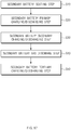
- the method for manufacturing the secondary battery according to the second embodiment of the present invention comprises: a seating step (S10) of sealing one or more secondary batteries 1 on a main body 10; a primary charging/discharging step (S20) of primarily charging the secondary battery 1 at a first voltage by using the charging/discharging device 300; a secondary charging/discharging step (S30) of secondarily charging and discharging the secondary battery 1 at a second voltage by using the charging/discharging device 300; a gas discharge step (S40) of discharging a gas generated in the secondary battery 1 to the outside by using a degassing device 100; and a tertiary charging/discharging step (S50) of tertiarily charging and discharging the secondary battery 1, from which the gas is discharged, at a third voltage by using the charging/discharging device 300.
- the plurality of secondary batteries 1 are seated to be arranged in a longitudinal direction of the main body 10.
- each of the secondary batteries 1 is seated in a state in which an electrode lead formed on the secondary battery is erected toward the charging/discharging device 300.
- a degassing device position adjustment step is further performed to adjust a position of the degassing device 100 so that the degassing device 100 is disposed on an upper portion of the secondary battery 1 by using the moving device 100.
- a piercing unit 110 and a gas discharge unit 120 move in a thickness direction of the secondary battery through a left/right moving unit 220 so that the secondary battery 1 is adjusted in position to be disposed between the piercing unit 110 and the gas discharge unit 120.
- the piercing unit 110 and the gas discharge unit 120 move in a longitudinal direction of the secondary battery through a front/rear moving unit 210 so that the piercing unit 110 and the gas discharge unit 120 are disposed in the same vertical line as a preset pierced portion of the secondary battery 1.
- an electrode lead of the secondary battery 1 seated on a main body 10 and a charging/discharging device 300 are connected to each other to perform the charging and discharging.
- the charging/discharging device 300 primarily charges the secondary battery 1 at the first voltage, and the first voltage may be 2.8 V or less.
- the primary charging/discharging of the secondary battery is performed, a small amount of gas is generated in the secondary battery to cause a swelling phenomenon.
- the secondary battery that is primarily charged and discharged is secondarily charged and discharged at the second voltage by using the charging/discharging device.
- the second voltage has a voltage higher than the first voltage. That is, the second voltage has a voltage ranging from 2.8 V to 4.0 V.
- the gas generated in the secondary battery is discharged to the outside by using the degassing device 100 according to the first embodiment of the present invention.
- the piercing unit 110 and the gas discharge unit 120 descend toward the secondary battery 1 through the elevation unit 160 so that the piercing unit 110 and the gas discharge unit 120 are disposed at a preset pierced portion of the secondary battery 1.
- an upper portion of the secondary battery 1, in which an electrolyte is not provided so that the electrolyte accommodated in the secondary battery 1 does not leak, is set as the pierced portion.
- a first sealing part 111a of a piercing body 111 provided in the piercing unit 110 seals one side of one surface of the secondary battery 1 while being closely attached to the one surface of the secondary battery 1
- a second sealing part 121a of a gas discharge body 121 provided in the gas discharge unit 120 seals one side of the other surface of the secondary battery 1 while being closely attached to the one side of the other surface of the secondary battery 1.
- the one side of the one surface of the secondary battery 1 may be pierced through the piercing unit 110 to form an opening hole, and suction force may be generated in the opening hole formed in the secondary battery through the gas discharge unit to discharge the gas within the secondary battery through the opening hole, thereby removing the gas within the secondary battery.
- a surface of the secondary battery, in which the opening hole is formed is sealed through a sealing unit 130 comprising a first heating member 131 provided in the piercing unit 110 and a second heating member 132 provided in the gas discharge unit 120 to seal the opening hole.
- the piercing unit 110 and the gas discharge unit 120 return to its original position through the moving unit 150, the elevation unit 160, a front/rear moving unit 210, and a left/right moving unit 220.
- the degassing device has the same configuration as the degassing device according to the first embodiment of the present invention, and thus, detailed description and function thereof will be omitted.
- the secondary battery 1 from which the gas is discharged is tertiarily charged and discharged at the third voltage by using the charging/discharging device 300.
- the third voltage has a voltage higher than the second voltage. That is, the third voltage is 4.0 V or more.
- the secondary charging/discharging step (S30) and the gas discharge step (S40) may be performed at the same time.
- the gas within the secondary battery may be discharged to prevent the swelling from occurring in the secondary battery, thereby improving charging/discharging efficiency.
Landscapes
- Chemical & Material Sciences (AREA)
- Chemical Kinetics & Catalysis (AREA)
- Electrochemistry (AREA)
- General Chemical & Material Sciences (AREA)
- Engineering & Computer Science (AREA)
- Manufacturing & Machinery (AREA)
- Secondary Cells (AREA)
Abstract
Description
- The present application claims the benefit of the priority of Korean Patent Application No.
10-2019-0001910, filed on January 07, 2019 - The present invention relates to a degassing device, and a facility and method for manufacturing a secondary battery comprising the same, and more particularly, to a degassing device that discharges and removes a gas generated in a secondary battery to the outside, and a facility and method for manufacturing the secondary battery comprising the same.
- In general, secondary batteries refer to chargeable and dischargeable batteries, unlike primary batteries that are not chargeable. The secondary batteries are being widely used in the high-tech electronic fields such as mobile phones, notebook computers, and camcorders.
- Also, the secondary batteries may be variously classified according to a structure of an electrode assembly. For example, the secondary batteries may be classified into a stacking type structure, a jelly-roll-type structure, or a stacking/folding type structure.
- Such a secondary battery comprises an electrode assembly and a case accommodating the electrode assembly, and the electrode assembly has a structure in which electrodes and separators are alternately stacked.
- A method for manufacturing the secondary battery having the above structure comprises a packaging process of accommodating an electrode assembly together with an electrolyte in a pouch to manufacture the secondary battery and a charging/discharging process of charging and discharging the secondary battery to activate the secondary battery.
- However, the secondary battery has a problem in that the secondary battery is swelled while generating a large amount of gas within the secondary battery during the charging/discharging. In particular, the secondary battery has a problem in that charging/discharging efficiency is significantly reduced due to the swelling.
- The present invention has been invented to solve the above problems, an object of the present invention is to provide a degassing device that discharges a gas generated in a secondary battery to the outside during the charging/discharging of the secondary battery to prevent the secondary battery from being swelled, thereby improving charging/discharging efficiency of the secondary battery, and a facility and method for manufacturing the secondary battery comprising the same.
- A degassing device according to a first embodiment of the present invention for achieving the above object is configured to discharge a gas generated in a secondary battery to the outside and comprises: a piercing unit comprising a piercing body disposed on one surface of the secondary battery to seal one side of the one surface of the secondary battery and a piercing member piercing the one side of the one surface of the secondary battery, which is sealed by the piercing body to form an opening hole; and a gas discharge unit comprising a gas discharge body disposed on the other surface of the secondary battery to seal one side of the other surface of the secondary battery, in which the opening hole is formed, and a gas discharge member discharging the gas within the secondary battery to the outside through the opening hole that is sealed by the gas discharge body, wherein the piercing member forms the opening hole passing from the one side of the one surface to the one side of the other surface of the secondary battery.
- The piercing body may comprise: a first sealing part formed on one surface to seal one side of the one surface of the secondary battery; a guide passage formed within an outlet hole formed inside the first sealing part and connected to the outlet hole; and first and second air injection parts through which air is injected into one side and the other side of the guide passage, respectively.
- The piercing member may comprise: a piercing part provided in the outlet hole and piercing the one side of the one surface of the secondary battery while being withdrawn out of the outlet hole to form the opening hole; and a piston part provided in the guide passage, withdrawing the piercing part out of the outlet hole while moving forward in a direction of the piercing part when the air is introduced through the first air injection part, and inserting the piercing part into the outlet hole while returning to its original position when the air is introduced into the guide passage through the second air injection part.
- The piercing part may comprise: a piercing pin provided in the outlet hole to pierce the one side of the one surface of the secondary battery while being withdrawn out of the outlet hole; and a piercing piece having one end connected to the piston part and the other end connected to the piercing pin to withdraw or insert the piercing pin out of or into the outlet hole when the piston part moves forward or returns to its original position.
- A guide hole formed in a longitudinal direction of the piston part may be formed in the piercing pin, wherein the guide hole may be gradually inclined toward the outlet hole from an end of one side that is close to the piston part to an end of the other side, the piercing piece may be provided with a coupling shaft that is freely rotatably coupled to the guide hole, and the coupling shaft may withdraw the piercing pin out of the outlet hole while moving to the end of the other side of the guide hole when the piercing piece moves forward together with the piston part and insert the piercing pin into the outlet hole while moving from the end of the other side to the end of the one side of the guide hole when the piercing pin returns to its original position together with the piston part.
- The gas discharge body may comprise: a second sealing part formed on one surface of the gas discharge body to seal one side of the other surface of the secondary battery; a suction hole provided inside the second sealing part; and an insertion passage provided in the gas discharge body and connected to the suction hole, wherein the gas discharge member may be inserted into the insertion passage to discharge the gas generated in the secondary battery to the outside through the opening hole disposed in the suction hole by using suction force.
- The degassing device may further comprise a sealing unit sealing a surface of the secondary battery in which the opening hole is formed, wherein the sealing unit may comprise first and second heating members pressing both side surfaces of the secondary battery, in which the opening hole is formed, and simultaneously applying heat to both the sides surfaces of the secondary battery to seal the opening hole, wherein the first and second heating members may press the secondary battery and simultaneously applies heat to the secondary battery to seal the opening hole.
- The first heating member may comprise a first insertion surface inserted into a first insertion groove formed in one surface of the piercing body in a shape that surrounds the first sealing part and a first sealing surface sealing the one side of the one surface of the secondary battery, in which the opening hole is formed, wherein the first sealing surface has a size less than that of the first insertion surface, and the second heating member may comprise a second insertion surface inserted into a second insertion groove formed in one surface of the gas discharge body in a shape that surrounds the second sealing part and a second sealing surface sealing the one side of the other surface of the secondary battery, in which the opening hole is formed, wherein the second sealing surface has a size less than that of the second insertion surface.
- Each of the first insertion groove and the insertion surface or each of the second insertion groove and the second insertion surface may have a polygonal shape.
- The degassing device may further comprise a cover unit provided with a first fixing cover fixing the first heating member inserted into the first insertion groove of the piercing body and a second fixing cover fixing the second heating member inserted into the second insertion groove of the gas discharge body.
- The degassing device may further comprise a moving unit that allows the piercing unit and the gas discharge unit to move in a direction in which the piercing unit and the gas discharge unit are close to each other so as to be closely attached to the secondary battery or in a direction in which the piercing unit and the gas discharge unit are away from each other so as not to be closely attached to the secondary battery.
- The moving unit may comprise a first moving member provided with a first fixing part fixed to the piercing unit and a first cylinder allowing the first fixing part to move so as to be closely attached to the one surface of the secondary battery or so as not to be closely attached to the secondary battery; and a second moving member provided with a second fixing part fixed to the gas discharge unit and a second cylinder allowing the second fixing part to move so as to be closely attached to the other surface of the secondary battery or so as not to be closely attached to the secondary battery.
- The degassing device may further comprise an elevation device allowing the piercing unit and the gas discharge unit to descend toward the secondary battery or return to its original position.
- The elevation unit may be connected to the piercing unit and the gas discharge unit and comprise a connection member connecting the piercing unit and the gas discharge unit so that the piercing unit and the gas discharge unit are movable in a direction of the secondary battery or a direction opposite to the direction of the secondary battery and a moving cylinder allowing the connection member to descend or return to its original position so that the piercing unit and the gas discharge unit descend or return to its original position in the direction of the secondary battery.
- The degassing device may further comprise a guide unit provided with a first guide member disposed on a bottom surface of the piercing unit to face the secondary battery and a second guide member disposed on a bottom surface of the gas discharge unit to face the secondary battery, wherein the bottom surfaces of the first and second guide members may be formed as inclined surfaces that are inclined toward the secondary battery.
- A facility for manufacturing a secondary battery according to a second embodiment of the present invention comprises: a main body on which the secondary battery is seated; and a degassing device which discharges a gas generated in the secondary battery seated on the main body to the outside, wherein the degassing device comprises: a piercing unit comprising a piercing body disposed on one surface of the secondary battery to seal one side of the one surface of the secondary battery and a piercing member piercing the one side of the one surface of the secondary battery, which is sealed by the piercing body to form an opening hole; and a gas discharge unit comprising a gas discharge body disposed on the other surface of the secondary battery to seal one side of the other surface of the secondary battery, in which the opening hole is formed, and a gas discharge member discharging the gas within the secondary battery to the outside through the opening hole that is sealed by the gas discharge body, wherein the piercing member forms the opening hole passing from the one side of the one surface to the one side of the other surface of the secondary battery.
- The facility may further comprise a moving device provided with a front/rear moving unit allowing the degassing device in a longitudinal direction of the secondary battery and a left/right moving unit allowing the degassing device in a thickness direction of the secondary battery seated on the main body.
- The facility may further comprise a charging/discharging device that charges and discharges the secondary battery seated on the main body to activate the secondary battery.
- A method for manufacturing a secondary battery according to a second embodiment of the present invention comprises: a seating step (S10) of sealing one or more secondary batteries on a
main body 10; a primary charging/discharging step (S20) of primarily charging the secondary battery seated on the main body at a first voltage by using a charging/discharging device; a secondary charging/discharging step (S30) of secondarily charging and discharging the secondary battery, which is primarily charged and discharged, at a second voltage by using the charging/discharging device; a gas discharge step (S40) of discharging a gas generated in the secondary battery, which is secondarily charged and discharged, to the outside by using the degassing device ofclaim 1; and a tertiary charging/discharging step (S50) of tertiarily charging and discharging thesecondary battery 1, from which the gas is discharged, at a third voltage by using the charging/discharging device. - The secondary charging/discharging step (S30) and the gas discharge step (S40) may be performed at the same time.
- The degassing device according to the present invention may comprise the piercing unit and the gas discharge unit. Therefore, the gas generated in the secondary battery may be effectively reduced to prevent the secondary battery from being deformed.
- In addition, the facility for manufacturing the secondary battery may comprise the degassing device provided with the piercing unit and the gas discharge unit. Therefore, the gas generated in the secondary battery may be discharged to the outside while the secondary battery is charged and discharged to prevent the secondary battery from being deformed, thereby improving the charging/discharging efficiency.
-
-
FIG. 1 is a perspective view of a degassing device according to a first embodiment of the present invention. -
FIG. 2 is a partial enlarged view ofFIG. 1 . -
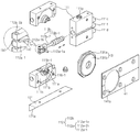
FIG. 3 is a perspective view illustrating a piercing unit and a gas discharge unit of the degassing device according to the first embodiment of the present invention. -
FIG. 4 is an exploded perspective view illustrating the piercing unit of the degassing device according to the first embodiment of the present invention. -
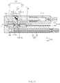
FIG. 5 is a cross-sectional view illustrating the piercing unit of the degassing device according to the first embodiment of the present invention. -
FIG. 6 is a cross-sectional view taken along line A-A ofFIG. 5 . -
FIG. 7 is a cross-sectional view taken along line B-B ofFIG. 5 . -
FIG. 8 is an exploded perspective view illustrating the gas discharge unit of the degassing device according to the first embodiment of the present invention. -
FIG. 9 is a cross-sectional view illustrating the gas discharge unit of the degassing device according to the first embodiment of the present invention. -
FIG. 10 is a cross-sectional view taken along line C-C ofFIG. 9 . -
FIGS. 11 to 13 are views illustrating a method for operating the degassing device according to the first embodiment of the present invention, whereinFIG. 11 is a cross-sectional view of a secondary battery sealing process,FIG. 12 is a cross-sectional view of a secondary battery piercing process, andFIG. 13 is a cross-sectional view illustrating a secondary battery gas discharging process. -
FIG. 14 is a perspective view illustrating a gap adjustment member of the degassing device according to the first embodiment of the present invention. -
FIG. 15 is a perspective view illustrating a facility for manufacturing a secondary battery according to a second embodiment of the present invention. -
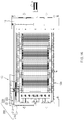
FIG. 16 is a plan view illustrating the facility for manufacturing a secondary battery according to the second embodiment of the present invention. -
FIG. 17 is a flowchart illustrating a method for manufacturing the second battery according to the second embodiment of the present invention. - Hereinafter, embodiments of the present invention will be described in detail with reference to the accompanying drawings in such a manner that the technical idea of the present invention may easily be carried out by a person with ordinary skill in the art to which the invention pertains. The present invention may, however, be embodied in different forms and should not be construed as limited to the embodiments set forth herein. In the drawings, anything unnecessary for describing the present invention will be omitted for clarity, and also like reference numerals in the drawings denote like elements.
- As illustrated in
FIGS. 1 and2 , adegassing device 100 according to a first embodiment of the present invention has a structure in which a gas generated in asecondary battery 1 is discharged to the outside and comprises apiercing unit 110, agas discharge unit 120, asealing unit 130, acover unit 140, a movingunit 150, anelevation unit 160, and aguide unit 170. - As illustrated in
FIGS. 3 to 7 , thepiercing unit 110 pierces the secondary battery to form an opening hole and comprises apiercing body 111 disposed on one surface of thesecondary battery 1 to seal one side of the one surface of thesecondary battery 1 and apiercing member 112 piercing the one side of the one surface of thesecondary battery 1, which is sealed by thepiercing body 111 to form anopening hole 1a. - Here, the piercing
member 112 pierces thesecondary battery 1 so that thesecondary battery 1 pass from the one side of the one surface to one side of the other side thereof, thereby forming theopening hole 1a. - The piercing
body 111 may comprises afirst sealing part 111a formed on one surface (a left surface of the piercing body when viewed inFIG. 3 ) to seal one side of the one surface of thesecondary battery 1, aguide passage 111c formed within anoutlet hole 111b formed inside thefirst sealing part 111a and connected to theoutlet hole 111b, and first and secondair injection parts guide passage 111c. - The
first sealing part 111a is formed on one surface of the piercingbody 111 in a circular frame shape. Thefirst sealing part 111a having the circular frame shape may be closely attached to one side of one surface of thesecondary battery 1 to seal the one side of the one surface of the secondary battery, which is disposed inside the sealingpart 111a. A pad member having heat resistance to improve sealability may be further provided on a front end of thefirst sealing part 111a. Thus, the sealability between thefirst sealing member 111a and the one side of the one surface of thesecondary battery 1 may be improved. - The
outlet hole 111b is formed in one surface of the piercingbody 111, which is disposed inside thefirst sealing part 111a, in particular, theoutlet hole 111b is formed as an outlet groove that is opened in a direction of the one surface of the piercingbody 111. - Also, a
protrusion 111b-1 protruding from the one surface of the piercingbody 111 is formed on an inlet of theoutlet hole 111b. Theprotrusion 111b-1 has a circular frame shape formed along an outer circumferential surface of theoutlet hole 111b. Thus, theprotrusion 111b-1 may stably support a piercing pin that is withdrawn out of theoutlet hole 111b to significantly prevent the piercing pin from moving. - The
outlet hole 111b may have a rectangular cross-sectional shape, and the piercing pin disposed in theoutlet hole 111b having the rectangular cross-sectional shape may also have a rectangular shape. As a result, even though the piercing pin is withdrawn or inserted along theoutlet hole 111b, the piercing pin may be prevented from rotating in a left or right direction, and thus, stable movement of the piercing pin may be induced. - The
guide passage 111c may be formed inside the piercingbody 111 in a longitudinal direction (a left/right direction when viewed inFIG. 5 ) of the piercingbody 111. Theguide passage 111c has one end (a left end when viewed inFIG. 5 ) connected to one side of theoutlet hole 111b and the other end (a right end when viewed inFIG. 5 ) that is finished by a fixingpiece 111f in a state of passing through the other side (a right surface of the piercing body when viewed inFIG. 5 ) of the piercingbody 111. - Particularly, referring to
FIG. 5 , theguide passage 111c comprises apiston chamber 111c-1 formed inside the other side of the piercingbody 111 and aconnection chamber 111c-2 connecting thepiston chamber 111c-1 to theoutlet hole 111b. - The first and second
air injection parts guide passage 111c. The firstair injection part 111d is connected to one side of theguide passage 111c, and the secondair injection part 111e is connected to the other side of theguide passage 111c. That is, the firstair injection part 111d injects the air into the one side of theguide passage 111c to allow a piston part provided in theguide passage 111c to move forward in a direction of the piercing part, and the secondair injection part 111e injects the air into the other side of theguide passage 111c to allow the piston part provided in theguide passage 111c to move backward in a direction opposite to the piercing part. - The piercing
member 112 comprises a piercingpart 112a provided in theoutlet hole 111b and piercing the one side of the one surface of thesecondary battery 1 while being withdrawn out of theoutlet hole 111b to form the opening hole and thepiston part 112b provided in theguide passage 111c, withdrawing the piercingpart 112a out of theoutlet hole 111b while moving forward in the direction of the piercingpart 112a when the air is introduced through the firstair injection part 111d, and inserting the piercingpart 112a into theoutlet hole 111b while moving backward in the direction opposite to the piercingpart 112a when the air is introduced into theguide passage 111c through the secondair injection part 111e. - For clear description of the present invention, hereinafter, the moving forward in the direction of the piercing
part 112a will be referred to as "forward movement", and moving backward in the direction opposite of the piercingpart 112a will be referred to as "backward movement". - The piercing
part 112a comprises a piercingpin 112a-1 provided in theoutlet hole 111b to pierce the one side of the one surface of thesecondary battery 1 while being withdrawn out of theoutlet hole 111b to form theopening hole 1a and a piercingpiece 112a-2 withdrawing or inserting the piercingpin 112a-1 into or out of theoutlet hole 111b when thepiston part 112b moves forward or backward. - The piercing
pin 112a-1 is configured to pierce the one side of the one surface of the secondary battery and has one end on which ablade 112a-1a for piercing the one side of the one surface of thesecondary battery 1 is formed and the other end in which aguide hole 112a-1b connected to the piercingpiece 112a-1 is formed. - Here, the
guide hole 112a-1b is formed to be inclined in a longitudinal direction of thepiston part 112b. That is, theguide hole 112a-1b may disposed near thepiston part 112b and formed to be inclined from an upper end a of an inlet side of theoutlet hole 111b to a lower end b disposed at a bottom side of theoutlet hole 111b. That is to say, referring toFIG. 6 , theguide hole 112a-1b is formed to be inclined from an upper end disposed at a right side to a lower end disposed at a right side. - The piercing
piece 112a-2 has one end connected to thepiston part 112b and the other end connected to the piercingpin 112a-1. As a result, the piercingpiece 112a-2 may be withdrawn from or inserted into theoutlet hole 111b when thepiston part 112b moves forward or backward. - Here, the piercing
piece 112a-2 is provided with acoupling shaft 112a-2a freely rotatably coupled to theguide hole 112a-1b. That is, as illustrated inFIG. 12 , thecoupling shaft 112a-2a of the piercingpiece 112a-2 withdraws the piercing pin out of the outlet hole while moving from the upper end a to the lower end b of theguide hole 112a-b when the piercing piece moves forward by the piston part. Also, as illustrated inFIG. 11 , thecoupling shaft 112a-2 of the piercingpiece 112a-2 inserts the piercing pin into theoutlet hole 111b while moving from the lower end b to the upper end a of theguide hole 112a-1b when the piercingpin 112a-2 moves backward by the piston part. - The
piston part 112b comprises apiston 112b-1 provided in thepiston chamber 111c-1 of theguide passage 111c and aconnection bar 112b-2 connected to the piercingpiece 112a-2 through theconnection chamber 111c-2. - An operation state of the piercing
unit 110 having the above-described configuration will be described as follows. - First, when the
first sealing part 111a provided on the piercingbody 111 is closely attached to the one side of the one surface of thesecondary battery 1, the one side of the one surface of thesecondary battery 1 may be sealed by thefirst sealing part 111a. In this state, when the air is injected into theguide passage 111c through the firstair injection part 111d of the piercingbody 111, thepiston part 112b allows the piercingpiece 112a-2 of the piercingpart 112a to move forward while moving forward, and the piercingpiece 112a-2 withdraws the piercingpin 112a-1 out of theoutlet hole 111b while moving forward. Thus, the piercingpin 112a-1 pierces the one side of the one surface of thesecondary battery 1 while being withdrawn out of theoutlet hole 111b to form the opening hole. - When the opening hole is completely formed, if the air is injected into the
guide passage 111c through the secondair injection part 111e of the piercingbody 111, thepiston part 112b allows the piercingpiece 112a-2 of the piercingpart 112a to move backward while moving backward, and the piercingpiece 112a-2 inserts the piercingpin 112a-1 into theoutlet hole 111b while moving backward. - Thus, the piercing
unit 110 having the above-described configuration may stably form the opening hole in the one surface of the secondary battery. - A
discharge part 111g connected to theguide passage 111c may be further formed in the piercingbody 111. Thedischarge part 111g may forcibly discharge the air introduced into theguide passage 111c to the outside. - As illustrated in
FIGS. 3 and8 to 10 , thegas discharge unit 120 comprises agas discharge body 121 disposed on the other surface of thesecondary battery 1 to seal the one side of the other surface of thesecondary battery 1, in which theopening hole 1a is formed, and agas discharge member 122 discharging a gas within thesecondary battery 1 to the outside through theopening hole 1a. - The
gas discharge body 121 comprises asecond sealing part 121a formed on one surface to seal one side of the other surface of thesecondary battery 1, asuction hole 121b provided inside thesecond sealing part 121a, and aninsertion passage 121c provided in thegas discharge body 121 and connected to thesuction hole 121b. - The
second sealing part 121a seals the one side of the other surface of thesecondary battery 1, which corresponds to thefirst sealing part 111a, and is formed on one surface of thegas discharge body 121 in a circular frame shape. Also, thesecond sealing part 121a having the circular frame shape is closely attached to the one side of the other surface of thesecondary battery 1. Therefore, the one side of the other surface of thesecondary battery 1, which is disposed inside thesecond sealing part 121a, is sealed. A pad member having heat resistance to improve sealability may be further provided on a front end of thesecond sealing part 121a. - The
gas discharge member 122 is inserted into theinsertion passage 121c to discharge the gas generated in thesecondary battery 1 to the outside through theopening hole 1a disposed in thesuction hole 121b by using suction force. - Thus, the
gas discharge unit 120 having the above-described configuration may discharge the gas generated in thesecondary battery 1 through theopening hole 1a formed in thesecondary battery 1 to remove the gas. - Hereinafter, a method for operating the
degassing device 100 having the above-described configuration according to the first embodiment of the present invention will be described. - That is, a method for operating the degassing device according to the first embodiment of the present invention comprises a secondary battery sealing process, a secondary battery piercing process, and a secondary battery gas discharging process.
- As illustrated in
FIG. 11 , in the secondary battery sealing process, a piercingunit 110 and agas discharge unit 120 are disposed on one surface and the other surface of the secondary battery to correspond to each other. - Next, the piercing
unit 110 and thegas discharge unit 120 move in a direction in which the piercingunit 110 and thegas discharge unit 120 are close to each other so as to be closely attached to thesecondary battery 1. Thus, afirst sealing part 111a of a piercingbody 111 provided in the piercingunit 110 seals one side of the one surface of thesecondary battery 1 while being closely attached to the one surface of thesecondary battery 1, and asecond sealing part 121a of agas discharge body 121 provided in thegas discharge unit 120 seals one side of the other surface of thesecondary battery 1 while being closely attached to the one side of the other surface of thesecondary battery 1. - As illustrated in
FIG. 12 , in the secondary battery piercing process, air is injected into apiston chamber 111c-1 of aguide passage 111c through a firstair injection part 111d of the piercingbody 111. Thus, apiston part 112b moves forward by the air injected into one side of thepiston chamber 111c-1, and the piercingpart 112a is withdrawn out of anoutlet hole 111b by thepiston part 112b to pierce the one side of the one surface of thesecondary battery 1, thereby forming an opening hole. - In more detail, when the
piston part 112b moves forward, a piercingpiece 112a-2 of the piercingpart 112a is interlocked with thepiston part 112b to move forward. Here, acoupling shaft 112a-2b formed on the piercingpiece 112a-2 presses a piercingpin 112a-1 toward the outside of theoutlet hole 111b while moving forward along a guide hole of the piercingpin 112a-1. As a result, the piercingpin 112a-1 is withdrawn out of theoutlet hole 111b to pierce the one side of the one surface of thesecondary battery 1, thereby forming the opening hole. Here, the piercing pin of a piercing member may form theopening hole 1a that passes from the one side of the one surface to the one side of the other surface of the secondary battery. - When the opening hole is completely formed, air is injected into the
piston chamber 111c-1 of theguide passage 111c through a secondair injection part 111e of the piercingbody 111. Thus, thepiston part 112b moves backward by the air injected into the other side of thepiston chamber 111c-1, and the piercingpart 112a is inserted into theoutlet hole 111b of the piercingbody 111 by thepiston part 112b. - In more detail, when the
piston part 112b moves backward, the piercingpiece 112a-2 of the piercingpart 112a is interlocked with thepiston part 112b to move backward. Here, the coupling shaft formed on the piercingpiece 112a-2 presses the piercingpin 112a-1 toward the inside of theoutlet hole 111b while moving backward along the guide hole of the piercingpin 112a-1. As a result, the piercingpin 112a-1 may be inserted into theoutlet hole 111b. - As illustrated in
FIG. 13 , in the secondary battery gas discharging process, when suction force is generated through thegas discharge member 122 provided in thegas discharge unit 120, the suction force is generated in asuction hole 121b provided inside thesecond sealing part 121a to forcibly suction the gas within thesecondary battery 1 through theopening hole 1a of thesecondary battery 1 so as to discharge the gas to the outside. - Thus, the
degassing device 100 according to the first embodiment of the present invention comprises the piercingunit 110 and thegas discharge unit 120 to effectively remove the gas generated in the secondary battery. - The
degassing device 100 according to the first embodiment of the present invention may further comprise a sealing unit sealing a surface of the secondary battery to seal theopening hole 1a formed in thesecondary battery 1. - As illustrated in
FIG. 4 , the sealingunit 130 comprises first andsecond heating members secondary battery 1, in which theopening hole 1a is formed, and simultaneously applying heat to both the sides surfaces of thesecondary battery 1 to seal theopening hole 1a. - As illustrated in
FIG. 4 , thefirst heating member 131 comprises afirst insertion surface 131a inserted into afirst insertion groove 111h formed in one surface of the piercingbody 111 in a shape that surrounds thefirst sealing part 111a and afirst sealing surface 131b pressing the one side of the one surface of thesecondary battery 1, in which theopening hole 1a is formed, and simultaneously applying heat to the one side of the one surface of thesecondary battery 1 to seal theopening hole 1a. Here, thefirst sealing surface 131b has a size less than that of thefirst insertion surface 131a to improve coupling with a first cover member. - As illustrated in
FIG. 8 , thesecond heating member 132 comprises asecond insertion surface 132a inserted into asecond insertion groove 121d formed in one surface of thegas discharge body 121 in a shape that surrounds thesecond sealing part 121a and asecond sealing surface 132b pressing the one side of the other surface of thesecondary battery 1, in which theopening hole 1a is formed, and simultaneously applying heat to the one side of the other surface of thesecondary battery 1 to seal theopening hole 1a. Here, thesecond sealing surface 132b has a size less than that of thesecond insertion surface 132a to improve coupling with a second cover member. - Each of the
first insertion groove 111h and thefirst insertion surface 131a or each of thesecond insertion groove 121d and thesecond insertion surface 132a has a polygonal shape. Thus, the first and second heating members may be fixed without rotating. - Therefore, the sealing
unit 130 may comprise the first andsecond heating members secondary battery 1, in which the opening hole is formed, and simultaneously heat the surface of thesecondary battery 1, thereby sealing the opening hole. - As illustrated in
FIGS. 4 and8 , thedegassing device 100 according to the first embodiment of the present invention may further comprise acover unit 140 fixing the first heating member to the piercing unit and fixing the second heating member to the gas discharge unit. - That is, the
cover unit 140 comprises afirst fixing cover 141 fixing thefirst heating member 131 inserted into thefirst insertion groove 111h of the piercingbody 111 and asecond fixing cover 142 fixing thesecond heating member 132 inserted into thesecond insertion groove 121d of thegas discharge body 121. - Here, the first fixing
cover 141 has a first through-hole 141a, which is coupled to the entire one surface of the piercingbody 111 to pass through thefirst sealing surface 131b of thefirst heating member 131. Thus, the first fixingcover 141 may support thefirst insertion surface 131a of thefirst heating member 131 inserted into thefirst insertion groove 111h to fix thefirst heating member 131, thereby preventing thefirst heating member 131 from being separated from the piercingbody 111. - Also, the
second fixing cover 142 has a second through-hole 142a, which is coupled to the entire one surface of thegas discharge body 121 to pass through thesecond sealing surface 132b of thesecond heating member 132. Thus, thesecond fixing cover 142 may support thesecond insertion surface 132a of thesecond heating member 132 inserted into thesecond insertion groove 121d to fix thesecond heating member 132, thereby preventing thesecond heating member 132 from being separated from thegas discharge body 121. - Therefore, the
cover unit 140 may stably fix the first heating member to the piercing unit and stably fix the second heating member to the gas discharge unit. - As illustrated in
FIGS. 1 and2 , thedegassing device 100 according to the first embodiment of the present invention may further comprise a movingunit 150 that allows the piercingunit 110 and thegas discharge unit 120 to move in a direction in which the piercingunit 110 and thegas discharge unit 120 are close to each other so as to be closely attached to thesecondary battery 1 or in a direction in which the piercingunit 110 and thegas discharge unit 120 are away from each other so as not to be closely attached to thesecondary battery 1. - That is, the moving
unit 150 comprises a first movingmember 151 allowing the piercingunit 110 to move so as to be closely attached to the one surface of the secondary battery or so as not to be closely attached to the secondary battery and a second movingmember 152 allowing thegas discharge unit 120 to move so as to be closely attached to the other surface of the secondary battery or so as not to be closely attached to the secondary battery. - The first moving
member 151 comprises afirst fixing part 151a fixed to the piercing unit and afirst cylinder 151b allowing thefirst fixing part 151a to move so as to be closely attached to the one surface of the secondary battery or so as not to be closely attached to the secondary battery. - The second moving
member 152 comprises asecond fixing part 152a fixed to the gas discharge unit and asecond cylinder 152b allowing thesecond fixing part 152b to move so as to be closely attached to the other surface of thesecondary battery 1 or so as not to be closely attached to thesecondary battery 1. - Thus, the moving
unit 150 may allow the piercingunit 110 and thegas discharge unit 120 to move in the direction in which the piercingunit 110 and thegas discharge unit 120 are close to each other so as to be closely attached to thesecondary battery 1 or in the direction in which the piercingunit 110 and thegas discharge unit 120 are away from each other so as not to be closely attached to thesecondary battery 1. - As illustrated in
FIG. 14 , the movingunit 150 may further comprise agap adjustment member 153 restricting a spreading gap between the piercingunit 110 and thegas discharge unit 120. That is, thegap adjustment member 153 comprises anadjustment pin 153a having one side, in which acircular hole 153a-1 is formed, and the other side, in which along hole 153a-2 is formed in a longitudinal direction, afirst bolt 153b coupled to thegas discharge body 121 through the circular hole of theadjustment pin 153a, and asecond bolt 153c coupled to the piercingbody 111 through thelong hole 153a-2 of theadjustment pin 153a. - Thus, in the
gap adjustment member 153, thesecond bolt 153 may move within thelong hole 153a-2 of theadjustment pin 153a when the piercingunit 110 and thegas discharge unit 120 move in the direction in which the piercingunit 110 and thegas discharge unit 120 are close to each other so as to be closely attached to thesecondary battery 1 or move in the direction in which the piercingunit 110 and thegas discharge unit 120 are away from each other so as not to be closely attached to thesecondary battery 1. Thus, the spreading gap between the piercingunit 110 and thegas discharge unit 120 may be adjusted. - As illustrated in
FIGS. 1 and2 , thedegassing device 100 according to the first embodiment of the present invention may further comprise anelevation device 160 allowing the piercingunit 110 and thegas discharge unit 120 to descend so as to be close to thesecondary battery 1 or ascend so as to be separated from thesecondary battery 1. - The
elevation unit 160 comprises aconnection member 161 connecting the piercingunit 110 to thegas discharge unit 120 and a movingcylinder 162 allowing theconnection member 161 to descend or return to its original position so that the piercingunit 110 and thegas discharge unit 120 descend or return to its original position in the direction of thesecondary battery 1. - That is, when the
elevation unit 160 allows theconnection member 161 to descend or ascend by the movingcylinder 162, the piercingunit 110 and thegas discharge unit 120, which are connected to theconnection member 161, may descend or ascend at the same time. - Therefore, the
elevation unit 160 may allow each of the piercingunit 110 and thegas discharge unit 120 to descend or return to its original position so that the piercingunit 110 and thegas discharge unit 120 are respectively disposed on the one surface and the other surface of thesecondary battery 1. - As illustrated in
FIGS. 4 and8 , thedegassing device 100 according to the first embodiment of the present invention may further comprise aguide unit 170 which guides the piercingunit 110 and thegas discharge unit 120 so as not to interfere with thesecondary battery 1 when the piercingunit 110 and thegas discharge unit 120 descend toward thesecondary battery 1. - The
guide unit 170 comprises afirst guide member 171 provided on a bottom surface of the piercingunit 110 toward thesecondary battery 1 and asecond guide member 172 provided on a bottom surface of thegas discharge unit 120 toward thesecondary battery 1. - Here, the bottom surfaces of the first and
second guide members inclined surfaces - Thus, the
guide unit 170 may guide thesecondary battery 1 through theinclined surfaces second guide members unit 110 and thegas discharge unit 120 descend toward the secondary battery to prevent the secondary battery from being pressed. - Hereinafter, in descriptions of another embodiment of the present invention, constituents having the same function as the above-mentioned embodiment have been given the same reference numeral in the drawings, and thus duplicated description will be omitted.
- As illustrated in
FIGS. 15 and16 , a facility for manufacturing a secondary battery according to a second embodiment of the present invention comprises amain body 10 on which thesecondary battery 1 is seated and adegassing device 100 discharging a gas generated in thesecondary battery 1 seated on themain body 10 to the outside. - The
main body 10 has a box shape and is provided with a plurality of jigs, on which the secondary battery is seated, on a bottom surface thereof. The plurality of jigs may be disposed in a longitudinal direction of the main body to seat a plurality of secondary batteries to be spaced a predetermined distance from each other. Here, each of the secondary batteries are seated on each of the jigs in a state in which an electrode lead of the secondary battery is erected horizontally to face a wall of the main body. - Referring to
FIGS. 1 to 14 , thedegassing device 100 is installed on a top surface of themain body 10 and has a structure in which a gas generated in thesecondary battery 1 seated on themain body 10 is discharged to the outside. - That is, the
degassing device 100 comprises a piercingunit 110 and agas discharge unit 120. The piercingunit 110 comprises a piercingbody 111 disposed on one surface of the secondary battery to seal one side of the one surface of the secondary battery and a piercingmember 112 piercing the one side of the one surface of thesecondary battery 1, which is sealed by the piercingbody 111, to form an opening hole. Also, thegas discharge unit 120 comprises agas discharge body 121 disposed on the other surface of thesecondary battery 1 to seal one side of the other surface of thesecondary battery 1, in which the opening hole is formed, and agas discharge member 122 discharging the gas within thesecondary battery 1 to the outside through the opening hole. - Here, the piercing
member 112 has the opening hole that passes from the one side of the one surface to the one side of the other surface of the secondary battery. - The
degassing device 100 has the same configuration as the degassing device according to the first embodiment of the present invention, and thus, detailed description thereof will be omitted. - Therefore, the facility for manufacturing the secondary battery according to the second embodiment of the present invention may effectively remove the gas generated in the secondary battery.
- The facility for manufacturing the secondary battery according to the second embodiment of the present invention further comprises a moving
device 200 allowing thedegassing device 100 to move in a longitudinal direction of thesecondary battery 1 seated on themain body 10 or move in a thickness direction of thesecondary battery 1. - That is, the moving
device 200 comprises a front/rear moving unit 210 allowing thedegassing device 100 in the longitudinal direction of thesecondary battery 1 and a left/right moving unit 220 allowing thedegassing device 100 in the thickness direction of thesecondary battery 1 seated on themain body 10. - The front/
rear moving unit 210 comprises a front/rear rail 211 provided in the longitudinal direction of the secondary battery seated on themain body 10 and a front/rear moving member 212 having one end coupled to the front/rear rail 211 and the other end coupled to thedegassing device 100 to allow thedegassing device 100 to move along the front/rear rail 211. Thus, the front/rear moving unit 210 may allow thedegassing device 100 to move in the longitudinal direction of thesecondary battery 1 so that thedegassing device 100 is accurately disposed on thesecondary battery 1. - The left/
right moving unit 220 comprises a left/right rail 221 provided in the thickness direction of the secondary battery seated on themain body 10 and a left/right moving member 222 having one end coupled to the left/right rail 221 and the other end coupled to thedegassing device 100 to allow thedegassing device 100 to move along the left/right rail 221. Thus, the left/right moving unit 220 may allow thedegassing device 100 to move in the thickness direction of thesecondary battery 1 so that thedegassing device 100 is accurately disposed on thesecondary battery 1. - Here, the front/
rear moving unit 210 allows the left/right moving unit 220 and thedegassing device 100 to move together in the front/rear direction of the secondary battery. Thus, when thedegassing device 100 moves, an interference between the front/rear moving unit 210 and the left/right moving unit 220 may be prevented. - The facility for manufacturing the secondary battery according to the second embodiment of the present invention further comprises a charging/discharging
device 300 charging and discharging the secondary battery seated on themain body 10 to activate the secondary battery. The charging/dischargingdevice 300 performs the charging/discharging through an electrode lead of the secondary battery seated on themain body 10. - Therefore, the facility for manufacturing the secondary battery according to the second embodiment of the present invention may stably charging and discharging the secondary battery and effectively discharge the gas generated in the secondary battery after the charging and discharging.
- Hereinafter, a method for manufacturing a secondary battery using the facility for manufacturing the secondary battery according to the second embodiment of the present invention will be described.
- The method for manufacturing the secondary battery according to the second embodiment of the present invention comprises: a seating step (S10) of sealing one or more
secondary batteries 1 on amain body 10; a primary charging/discharging step (S20) of primarily charging thesecondary battery 1 at a first voltage by using the charging/dischargingdevice 300; a secondary charging/discharging step (S30) of secondarily charging and discharging thesecondary battery 1 at a second voltage by using the charging/dischargingdevice 300; a gas discharge step (S40) of discharging a gas generated in thesecondary battery 1 to the outside by using adegassing device 100; and a tertiary charging/discharging step (S50) of tertiarily charging and discharging thesecondary battery 1, from which the gas is discharged, at a third voltage by using the charging/dischargingdevice 300. - Referring to
FIG. 15 , in the secondary battery seating step (S10), the plurality ofsecondary batteries 1 are seated to be arranged in a longitudinal direction of themain body 10. Here, each of thesecondary batteries 1 is seated in a state in which an electrode lead formed on the secondary battery is erected toward the charging/dischargingdevice 300. - After the secondary battery seating step (S10), a degassing device position adjustment step is further performed to adjust a position of the
degassing device 100 so that thedegassing device 100 is disposed on an upper portion of thesecondary battery 1 by using the movingdevice 100. - Referring to
FIG. 1 , in the degassing device position adjustment step, a piercingunit 110 and agas discharge unit 120 move in a thickness direction of the secondary battery through a left/right moving unit 220 so that thesecondary battery 1 is adjusted in position to be disposed between the piercingunit 110 and thegas discharge unit 120. - Next, the piercing
unit 110 and thegas discharge unit 120 move in a longitudinal direction of the secondary battery through a front/rear moving unit 210 so that the piercingunit 110 and thegas discharge unit 120 are disposed in the same vertical line as a preset pierced portion of thesecondary battery 1. - In the primary charging/discharging step, an electrode lead of the
secondary battery 1 seated on amain body 10 and a charging/dischargingdevice 300 are connected to each other to perform the charging and discharging. Here, the charging/dischargingdevice 300 primarily charges thesecondary battery 1 at the first voltage, and the first voltage may be 2.8 V or less. When the primary charging/discharging of the secondary battery is performed, a small amount of gas is generated in the secondary battery to cause a swelling phenomenon. - In the secondary charging/discharging step, the secondary battery that is primarily charged and discharged is secondarily charged and discharged at the second voltage by using the charging/discharging device. Here, the second voltage has a voltage higher than the first voltage. That is, the second voltage has a voltage ranging from 2.8 V to 4.0 V. When the secondary charging/discharging of the secondary battery is performed, the amount of gas generated in the secondary battery increases to significantly increase in swelling phenomenon. As a result, the gas generated in the secondary battery is discharged and removed through the gas discharge step.
- In the gas discharge step, the gas generated in the secondary battery is discharged to the outside by using the
degassing device 100 according to the first embodiment of the present invention. - That is, referring to
FIGS. 1 to 14 , in thedegassing device 100, the piercingunit 110 and thegas discharge unit 120 descend toward thesecondary battery 1 through theelevation unit 160 so that the piercingunit 110 and thegas discharge unit 120 are disposed at a preset pierced portion of thesecondary battery 1. - Here, an upper portion of the
secondary battery 1, in which an electrolyte is not provided so that the electrolyte accommodated in thesecondary battery 1 does not leak, is set as the pierced portion. - Next, the piercing
unit 110 and thegas discharge unit 120 move in a direction in which the piercingunit 110 and thegas discharge unit 120 are close to each other through the movingunit 150, and then, the piercingunit 110 and thegas discharge unit 120 are pressed to both surfaces of thesecondary battery 1. Here, afirst sealing part 111a of a piercingbody 111 provided in the piercingunit 110 seals one side of one surface of thesecondary battery 1 while being closely attached to the one surface of thesecondary battery 1, and asecond sealing part 121a of agas discharge body 121 provided in thegas discharge unit 120 seals one side of the other surface of thesecondary battery 1 while being closely attached to the one side of the other surface of thesecondary battery 1. - Next, the one side of the one surface of the
secondary battery 1 may be pierced through the piercingunit 110 to form an opening hole, and suction force may be generated in the opening hole formed in the secondary battery through the gas discharge unit to discharge the gas within the secondary battery through the opening hole, thereby removing the gas within the secondary battery. - Next, a surface of the secondary battery, in which the opening hole is formed, is sealed through a
sealing unit 130 comprising afirst heating member 131 provided in the piercingunit 110 and asecond heating member 132 provided in thegas discharge unit 120 to seal the opening hole. - When the above processes are completely performed, the piercing
unit 110 and thegas discharge unit 120 return to its original position through the movingunit 150, theelevation unit 160, a front/rear moving unit 210, and a left/right moving unit 220. - The degassing device has the same configuration as the degassing device according to the first embodiment of the present invention, and thus, detailed description and function thereof will be omitted.
- In the tertiary charging/discharging step, the
secondary battery 1 from which the gas is discharged is tertiarily charged and discharged at the third voltage by using the charging/dischargingdevice 300. Here, the third voltage has a voltage higher than the second voltage. That is, the third voltage is 4.0 V or more. - The secondary charging/discharging step (S30) and the gas discharge step (S40) may be performed at the same time. Thus, when the secondary charging/discharging of the secondary battery is performed, the gas within the secondary battery may be discharged to prevent the swelling from occurring in the secondary battery, thereby improving charging/discharging efficiency.
- Accordingly, the scope of the present invention is defined by the appended claims more than the foregoing description and the exemplary embodiments described therein. Various modifications made within the meaning of an equivalent of the claims of the invention and within the claims are to be regarded to be in the scope of the present invention.
Claims (15)
- A degassing device, which discharges a gas generated in a secondary battery to the outside, the degassing device comprising:a piercing unit comprising a piercing body disposed on one surface of the secondary battery to seal one side of the one surface of the secondary battery and a piercing member piercing the one side of the one surface of the secondary battery, which is sealed by the piercing body to form an opening hole; anda gas discharge unit comprising a gas discharge body disposed on the other surface of the secondary battery to seal one side of the other surface of the secondary battery, in which the opening hole is formed, and a gas discharge member discharging the gas within the secondary battery to the outside through the opening hole that is sealed by the gas discharge body,wherein the piercing member forms the opening hole passing from the one side of the one surface to the one side of the other surface of the secondary battery.
- The degassing device of claim 1, wherein the piercing body comprises:a first sealing part formed on one surface to seal one side of the one surface of the secondary battery;a guide passage formed within an outlet hole formed inside the first sealing part and connected to the outlet hole; andfirst and second air injection parts through which air is injected into one side and the other side of the guide passage, respectively.
- The degassing device of claim 2, wherein the piercing member comprises:a piercing part provided in the outlet hole and piercing the one side of the one surface of the secondary battery while being withdrawn out of the outlet hole to form the opening hole; anda piston part provided in the guide passage, withdrawing the piercing part out of the outlet hole while moving forward in a direction of the piercing part when the air is introduced through the first air injection part, and inserting the piercing part into the outlet hole while returning to its original position when the air is introduced into the guide passage through the second air injection part.
- The degassing device of claim 3, wherein the piercing part comprises:a piercing pin provided in the outlet hole to pierce the one side of the one surface of the secondary battery while being withdrawn out of the outlet hole; anda piercing piece having one end connected to the piston part and the other end connected to the piercing pin to withdraw or insert the piercing pin out of or into the outlet hole when the piston part moves forward or returns to its original position.
- The degassing device of claim 4, wherein a guide hole formed in a longitudinal direction of the piston part is formed in the piercing pin, wherein the guide hole is gradually inclined toward the outlet hole from an end of one side that is close to the piston part to an end of the other side,
the piercing piece is provided with a coupling shaft that is freely rotatably coupled to the guide hole, and
the coupling shaft withdraws the piercing pin out of the outlet hole while moving to the end of the other side of the guide hole when the piercing piece moves forward together with the piston part and inserts the piercing pin into the outlet hole while moving from the end of the other side to the end of the one side of the guide hole when the piercing pin returns to its original position together with the piston part. - The degassing device of claim 1, wherein the gas discharge body comprises:a second sealing part formed on one surface of the gas discharge body to seal one side of the other surface of the secondary battery;a suction hole provided inside the second sealing part; andan insertion passage provided in the gas discharge body and connected to the suction hole,wherein the gas discharge member is inserted into the insertion passage to discharge the gas generated in the secondary battery to the outside through the opening hole disposed in the suction hole by using suction force.
- The degassing device of claim 1, wherein the degassing device further comprises a sealing unit sealing a surface of the secondary battery in which the opening hole is formed,
wherein the sealing unit comprises first and second heating members pressing both side surfaces of the secondary battery, in which the opening hole is formed, and simultaneously applying heat to both the sides surfaces of the secondary battery to seal the opening hole,
wherein the first and second heating members press the secondary battery and simultaneously applies heat to the secondary battery to seal the opening hole. - The degassing device of claim 7, wherein the first heating member comprises a first insertion surface inserted into a first insertion groove formed in one surface of the piercing body in a shape that surrounds the first sealing part and a first sealing surface sealing the one side of the one surface of the secondary battery, in which the opening hole is formed, wherein the first sealing surface has a size less than that of the first insertion surface, and
the second heating member comprises a second insertion surface inserted into a second insertion groove formed in one surface of the gas discharge body in a shape that surrounds the second sealing part and a second sealing surface sealing the one side of the other surface of the secondary battery, in which the opening hole is formed, wherein the second sealing surface has a size less than that of the second insertion surface. - The degassing device of claim 8, wherein each of the first insertion groove and the insertion surface or each of the second insertion groove and the second insertion surface has a polygonal shape.
- The degassing device of claim 9, further comprising a cover unit provided with a first fixing cover fixing the first heating member inserted into the first insertion groove of the piercing body and a second fixing cover fixing the second heating member inserted into the second insertion groove of the gas discharge body.
- The degassing device of claim 1, further comprising a moving unit that allows the piercing unit and the gas discharge unit to move in a direction in which the piercing unit and the gas discharge unit are close to each other so as to be closely attached to the secondary battery or in a direction in which the piercing unit and the gas discharge unit are away from each other so as not to be closely attached to the secondary battery.
- The degassing device of claim 1, further comprising an elevation device allowing the piercing unit and the gas discharge unit to descend toward the secondary battery or return to its original position.
- The degassing device of claim 12, further comprising a guide unit provided with a first guide member disposed on a bottom surface of the piercing unit to face the secondary battery and a second guide member disposed on a bottom surface of the gas discharge unit to face the secondary battery,
wherein the bottom surfaces of the first and second guide members are formed as inclined surfaces that are inclined toward the secondary battery. - A facility for manufacturing a secondary battery, the facility comprising:a main body on which the secondary battery is seated; anda degassing device which discharges a gas generated in the secondary battery seated on the main body to the outside,wherein the degassing device comprises:a piercing unit comprising a piercing body disposed on one surface of the secondary battery to seal one side of the one surface of the secondary battery and a piercing member piercing the one side of the one surface of the secondary battery, which is sealed by the piercing body to form an opening hole; anda gas discharge unit comprising a gas discharge body disposed on the other surface of the secondary battery to seal one side of the other surface of the secondary battery, in which the opening hole is formed, and a gas discharge member discharging the gas within the secondary battery to the outside through the opening hole that is sealed by the gas discharge body,wherein the piercing member forms the opening hole passing from the one side of the one surface to the one side of the other surface of the secondary battery.
- A method for manufacturing a secondary battery, the method comprising:a seating step (S10) of sealing one or more secondary batteries on a main body 10;a primary charging/discharging step (S20) of primarily charging the secondary battery seated on the main body at a first voltage by using a charging/discharging device;a secondary charging/discharging step (S30) of secondarily charging and discharging the secondary battery, which is primarily charged and discharged, at a second voltage by using the charging/discharging device;a gas discharge step (S40) of discharging a gas generated in the secondary battery, which is secondarily charged and discharged, to the outside by using the degassing device of claim 1; anda tertiary charging/discharging step (S50) of tertiarily charging and discharging the secondary battery 1, from which the gas is discharged, at a third voltage by using the charging/discharging device.
Applications Claiming Priority (2)
| Application Number | Priority Date | Filing Date | Title |
|---|---|---|---|
| KR1020190001910A KR102389408B1 (en) | 2019-01-07 | 2019-01-07 | Degasing device, producing facility and producing method of secondary battery comprising the same |
| PCT/KR2019/013817 WO2020145490A1 (en) | 2019-01-07 | 2019-10-21 | Degassing device, secondary battery manufacturing facility including same, and secondary battery manufacturing method |
Publications (3)
| Publication Number | Publication Date |
|---|---|
| EP3734693A1 true EP3734693A1 (en) | 2020-11-04 |
| EP3734693A4 EP3734693A4 (en) | 2021-04-07 |
| EP3734693B1 EP3734693B1 (en) | 2025-07-23 |
Family
ID=71520770
Family Applications (1)
| Application Number | Title | Priority Date | Filing Date |
|---|---|---|---|
| EP19909167.9A Active EP3734693B1 (en) | 2019-01-07 | 2019-10-21 | Degassing device, and facility and method for manufacturing secondary battery comprising the same. |
Country Status (7)
| Country | Link |
|---|---|
| US (1) | US11362378B2 (en) |
| EP (1) | EP3734693B1 (en) |
| KR (1) | KR102389408B1 (en) |
| CN (1) | CN111819713B (en) |
| ES (1) | ES3037622T3 (en) |
| HU (1) | HUE072381T2 (en) |
| WO (1) | WO2020145490A1 (en) |
Cited By (4)
| Publication number | Priority date | Publication date | Assignee | Title |
|---|---|---|---|---|
| EP4203123A1 (en) * | 2021-12-24 | 2023-06-28 | TM Plaza Co., Ltd. | Degassing device for battery cell |
| EP4243133A4 (en) * | 2020-11-03 | 2024-10-16 | Apro Co., Ltd | PRESSURE ACTIVATION DEVICE WITH DEGASSING UNIT |
| IT202300021828A1 (en) * | 2023-10-19 | 2025-04-19 | Digatron Systems S R L | DEVICE FOR HOLDING AND HANDLING LITHIUM BATTERY CELLS BEING MADE AND METHOD FOR MANUFACTURING A MULTIPLE LITHIUM BATTERY CELLS USING THE DEVICE |
| EP4589704A4 (en) * | 2023-05-11 | 2026-04-15 | Lg Energy Solution Ltd | DEVICE FOR MANUFACTURING A BATTERY CELL |
Families Citing this family (14)
| Publication number | Priority date | Publication date | Assignee | Title |
|---|---|---|---|---|
| CN114902481B (en) * | 2020-09-25 | 2024-02-09 | 株式会社Lg新能源 | Degassing device and degassing method for secondary battery |
| US12451557B2 (en) | 2020-09-25 | 2025-10-21 | Lg Energy Solution, Ltd. | Gas removing device and method for removing gas from a pouch type case of a secondary battery |
| KR102853956B1 (en) * | 2021-10-08 | 2025-09-03 | 주식회사 엘지에너지솔루션 | Device for activating secondary battery and activating method for the same |
| KR102873029B1 (en) * | 2021-11-12 | 2025-10-17 | 주식회사 엘지에너지솔루션 | Degassing apparatus for secondary battery |
| KR102940102B1 (en) * | 2021-11-24 | 2026-03-16 | 주식회사 엘지에너지솔루션 | Formation device for battery cells |
| KR102501255B1 (en) * | 2022-01-21 | 2023-02-17 | 주식회사 티엠프라자 | Battery cell gas removal modul |
| KR102428663B1 (en) * | 2022-04-22 | 2022-08-03 | (주)하나기술 | Degassing apparatus for secondary battery |
| KR102607707B1 (en) * | 2022-09-06 | 2023-11-29 | 주식회사티엠프라자 | Secondary battery degassing module |
| KR102537775B1 (en) * | 2022-10-07 | 2023-06-01 | (주)원터치 | Press puncher with improved operating speed by performing various types of processing in each operation cycle by means of punch selectively fixed to the bottom dead center during punching, and by rapidly returning punch to its original position in each operation cycle by pneumatic |
| JP2026503843A (en) * | 2022-12-23 | 2026-01-30 | エルジー エナジー ソリューション リミテッド | Lithium secondary battery and its manufacturing method |
| KR102557185B1 (en) * | 2022-12-27 | 2023-07-19 | 주식회사티엠프라자 | Degassing module for secondary battery pouch |
| KR102557189B1 (en) * | 2023-01-17 | 2023-07-20 | 주식회사티엠프라자 | Degassing module for secondary battery pouch |
| WO2025211641A1 (en) * | 2024-04-05 | 2025-10-09 | 주식회사 엘지에너지솔루션 | Secondary battery manufacturing apparatus and secondary battery manufacturing method using same |
| EP4648147B1 (en) * | 2024-05-10 | 2026-02-25 | TM Plaza Co., Ltd. | Process unit for secondary cell battery manufacture |
Family Cites Families (20)
| Publication number | Priority date | Publication date | Assignee | Title |
|---|---|---|---|---|
| JP2000353547A (en) | 1999-06-08 | 2000-12-19 | Fuji Elelctrochem Co Ltd | Degassing method for prismatic lithium ion secondary battery |
| JP2001283923A (en) | 2000-03-30 | 2001-10-12 | Matsushita Electric Ind Co Ltd | Battery manufacturing method |
| KR100921398B1 (en) | 2007-02-15 | 2009-10-14 | (주)제이티 | Picker of transfer tool and transfer tool with it |
| KR101304870B1 (en) * | 2010-12-02 | 2013-09-06 | 주식회사 엘지화학 | Method for Manufacturing Battery Cell and Battery Cell Manufactured Thereby |
| KR101605936B1 (en) * | 2013-05-02 | 2016-03-23 | 주식회사 엘지화학 | Battery pack capable of releasing gas inside of pouch type battery cell |
| KR101558049B1 (en) * | 2013-09-30 | 2015-10-06 | 주식회사 엘지화학 | Method for manufacturing second battery |
| US10121999B2 (en) | 2013-12-11 | 2018-11-06 | Nissan Motor Co., Ltd. | Degassing hole formation process and degassing hole formation apparatus for secondary battery |
| JP6292024B2 (en) | 2014-05-21 | 2018-03-14 | 日産自動車株式会社 | Method for producing film-clad battery |
| KR102234702B1 (en) | 2014-09-16 | 2021-04-01 | 삼성에스디아이 주식회사 | Case assembly, Prismatic secondary battery, and the fabrication method thereof |
| KR101791535B1 (en) * | 2014-12-23 | 2017-11-20 | 주식회사 엘지화학 | Method for Manufacturing Battery Cell by Device for Eliminating Gas from Battery Cell |
| JP6637955B2 (en) | 2015-02-16 | 2020-01-29 | 株式会社エンビジョンAescジャパン | Manufacturing method of lithium ion secondary battery |
| KR101880340B1 (en) * | 2015-04-01 | 2018-08-17 | 주식회사 엘지화학 | Device and method for removing gas of battery cell |
| DE102015007196A1 (en) * | 2015-06-09 | 2016-12-15 | Industrie-Partner Gmbh Radebeul-Coswig | "Method for producing electrolyte pouch cells for electric battery arrangements, corresponding device and electrolyte pouch cell" |
| KR101845958B1 (en) | 2015-08-17 | 2018-04-05 | 에스케이이노베이션 주식회사 | Method of preparing lithium secondary battery and lithium secondary battery prepared from the smae |
| KR101748362B1 (en) | 2016-02-02 | 2017-06-19 | (주)엔에스 | Method for manufacturing pouch secondary battery |
| KR102518866B1 (en) | 2016-03-03 | 2023-04-06 | 에스케이온 주식회사 | Secondary battery having vent portion |
| KR102217443B1 (en) * | 2016-11-30 | 2021-02-22 | 주식회사 엘지화학 | Gas removal device and gas removal method for rechargeable battery |
| KR102092269B1 (en) * | 2016-12-01 | 2020-03-23 | 주식회사 엘지화학 | Battery cell degassing apparatus |
| KR20180062837A (en) * | 2016-12-01 | 2018-06-11 | 대덕대학산학협력단 | Smart dongle system and method using internet of things complex modular device |
| KR102067715B1 (en) | 2016-12-01 | 2020-01-17 | 주식회사 엘지화학 | Battery cell degassing apparatus |
-
2019
- 2019-01-07 KR KR1020190001910A patent/KR102389408B1/en active Active
- 2019-10-21 ES ES19909167T patent/ES3037622T3/en active Active
- 2019-10-21 CN CN201980009607.7A patent/CN111819713B/en active Active
- 2019-10-21 US US16/966,299 patent/US11362378B2/en active Active
- 2019-10-21 HU HUE19909167A patent/HUE072381T2/en unknown
- 2019-10-21 EP EP19909167.9A patent/EP3734693B1/en active Active
- 2019-10-21 WO PCT/KR2019/013817 patent/WO2020145490A1/en not_active Ceased
Cited By (5)
| Publication number | Priority date | Publication date | Assignee | Title |
|---|---|---|---|---|
| EP4243133A4 (en) * | 2020-11-03 | 2024-10-16 | Apro Co., Ltd | PRESSURE ACTIVATION DEVICE WITH DEGASSING UNIT |
| EP4203123A1 (en) * | 2021-12-24 | 2023-06-28 | TM Plaza Co., Ltd. | Degassing device for battery cell |
| EP4589704A4 (en) * | 2023-05-11 | 2026-04-15 | Lg Energy Solution Ltd | DEVICE FOR MANUFACTURING A BATTERY CELL |
| IT202300021828A1 (en) * | 2023-10-19 | 2025-04-19 | Digatron Systems S R L | DEVICE FOR HOLDING AND HANDLING LITHIUM BATTERY CELLS BEING MADE AND METHOD FOR MANUFACTURING A MULTIPLE LITHIUM BATTERY CELLS USING THE DEVICE |
| EP4542702A1 (en) * | 2023-10-19 | 2025-04-23 | Digatron Systems S.r.l. | Device for holding and moving lithium battery cells during production and method for producing a plurality of lithium battery cells which uses the device |
Also Published As
| Publication number | Publication date |
|---|---|
| US20200373631A1 (en) | 2020-11-26 |
| ES3037622T3 (en) | 2025-10-03 |
| HUE072381T2 (en) | 2025-11-28 |
| US11362378B2 (en) | 2022-06-14 |
| KR102389408B1 (en) | 2022-04-22 |
| CN111819713A (en) | 2020-10-23 |
| CN111819713B (en) | 2022-09-13 |
| EP3734693A4 (en) | 2021-04-07 |
| KR20200085589A (en) | 2020-07-15 |
| EP3734693B1 (en) | 2025-07-23 |
| WO2020145490A1 (en) | 2020-07-16 |
Similar Documents
| Publication | Publication Date | Title |
|---|---|---|
| EP3734693B1 (en) | Degassing device, and facility and method for manufacturing secondary battery comprising the same. | |
| EP4123777A1 (en) | Secondary battery and manufacturing method thereof | |
| RU2703451C2 (en) | Method of making galvanic package elements for electric batteries, corresponding device and galvanic package element | |
| DE112013005284B4 (en) | Sealed battery manufacturing method, sealed battery sealing member, and sealed battery | |
| US20150089800A1 (en) | Method of manufacturing secondary battery | |
| EP4239705B1 (en) | Coating die for lithium secondary battery, including removable spacer shims | |
| KR101327777B1 (en) | Battery Module | |
| KR102394494B1 (en) | System and method for producing secondary battery | |
| EP4343945A1 (en) | Battery module for preventing chain ignition and method for manufacturing same | |
| US20160293918A1 (en) | Lead-acid battery and method of manufacturing lid member of lead-acid battery | |
| EP4187687A1 (en) | Battery cell | |
| KR20080089159A (en) | Square battery | |
| KR102092270B1 (en) | Apparatus and method for detecting leakage of pouch-typed battery cell | |
| US20090075169A1 (en) | Secondary battery | |
| KR20150030861A (en) | Pouched type case, battery cell and manufacturing method of battery cell | |
| KR101715915B1 (en) | Redox flow battery | |
| KR20170116510A (en) | Secondary battery | |
| KR102236347B1 (en) | Method for Manufacturing Secondary Battery | |
| KR102752406B1 (en) | Secondary battery with additional structures that can improve long term characteristics and manufacturing method thereof | |
| KR20000075255A (en) | Lithium polymer battery and method for manufacturing the same | |
| KR20220090279A (en) | Battery cell, apparatus for injecting electrolyte for battery cell, and electrolyte injection method using the same | |
| KR102113654B1 (en) | Manufacturing mathod of battery cell | |
| EP4685996A1 (en) | Electrolyte removing device | |
| KR20160051444A (en) | Electrolyte supplement system for the secondary battery and Method of electrolyte supplement for the secondary battery using the same | |
| EP4336609A1 (en) | Gas removal equipment for secondary battery |
Legal Events
| Date | Code | Title | Description |
|---|---|---|---|
| STAA | Information on the status of an ep patent application or granted ep patent |
Free format text: STATUS: THE INTERNATIONAL PUBLICATION HAS BEEN MADE |
|
| PUAI | Public reference made under article 153(3) epc to a published international application that has entered the european phase |
Free format text: ORIGINAL CODE: 0009012 |
|
| STAA | Information on the status of an ep patent application or granted ep patent |
Free format text: STATUS: REQUEST FOR EXAMINATION WAS MADE |
|
| 17P | Request for examination filed |
Effective date: 20200731 |
|
| AK | Designated contracting states |
Kind code of ref document: A1 Designated state(s): AL AT BE BG CH CY CZ DE DK EE ES FI FR GB GR HR HU IE IS IT LI LT LU LV MC MK MT NL NO PL PT RO RS SE SI SK SM TR |
|
| AX | Request for extension of the european patent |
Extension state: BA ME |
|
| REG | Reference to a national code |
Ref country code: DE Ref legal event code: R079 Ref country code: DE Ref legal event code: R079 Ref document number: 602019073083 Country of ref document: DE Free format text: PREVIOUS MAIN CLASS: H01M0002120000 Ipc: H01M0010040000 |
|
| A4 | Supplementary search report drawn up and despatched |
Effective date: 20210310 |
|
| RIC1 | Information provided on ipc code assigned before grant |
Ipc: H01M 10/04 20060101AFI20210303BHEP Ipc: H01M 50/183 20210101ALI20210303BHEP Ipc: H01M 50/342 20210101ALI20210303BHEP Ipc: H01M 10/44 20060101ALI20210303BHEP |
|
| RAP1 | Party data changed (applicant data changed or rights of an application transferred) |
Owner name: LG ENERGY SOLUTION LTD. |
|
| RAP3 | Party data changed (applicant data changed or rights of an application transferred) |
Owner name: LG ENERGY SOLUTION, LTD. |
|
| DAV | Request for validation of the european patent (deleted) | ||
| DAX | Request for extension of the european patent (deleted) | ||
| STAA | Information on the status of an ep patent application or granted ep patent |
Free format text: STATUS: EXAMINATION IS IN PROGRESS |
|
| 17Q | First examination report despatched |
Effective date: 20221208 |
|
| GRAP | Despatch of communication of intention to grant a patent |
Free format text: ORIGINAL CODE: EPIDOSNIGR1 |
|
| STAA | Information on the status of an ep patent application or granted ep patent |
Free format text: STATUS: GRANT OF PATENT IS INTENDED |
|
| INTG | Intention to grant announced |
Effective date: 20241104 |
|
| GRAJ | Information related to disapproval of communication of intention to grant by the applicant or resumption of examination proceedings by the epo deleted |
Free format text: ORIGINAL CODE: EPIDOSDIGR1 |
|
| STAA | Information on the status of an ep patent application or granted ep patent |
Free format text: STATUS: EXAMINATION IS IN PROGRESS |
|
| P01 | Opt-out of the competence of the unified patent court (upc) registered |
Free format text: CASE NUMBER: APP_65645/2024 Effective date: 20241212 |
|
| INTC | Intention to grant announced (deleted) | ||
| GRAP | Despatch of communication of intention to grant a patent |
Free format text: ORIGINAL CODE: EPIDOSNIGR1 |
|
| STAA | Information on the status of an ep patent application or granted ep patent |
Free format text: STATUS: GRANT OF PATENT IS INTENDED |
|
| GRAJ | Information related to disapproval of communication of intention to grant by the applicant or resumption of examination proceedings by the epo deleted |
Free format text: ORIGINAL CODE: EPIDOSDIGR1 |
|
| STAA | Information on the status of an ep patent application or granted ep patent |
Free format text: STATUS: EXAMINATION IS IN PROGRESS |
|
| INTG | Intention to grant announced |
Effective date: 20250218 |
|
| INTC | Intention to grant announced (deleted) | ||
| GRAP | Despatch of communication of intention to grant a patent |
Free format text: ORIGINAL CODE: EPIDOSNIGR1 |
|
| STAA | Information on the status of an ep patent application or granted ep patent |
Free format text: STATUS: GRANT OF PATENT IS INTENDED |
|
| INTG | Intention to grant announced |
Effective date: 20250507 |
|
| GRAS | Grant fee paid |
Free format text: ORIGINAL CODE: EPIDOSNIGR3 |
|
| GRAA | (expected) grant |
Free format text: ORIGINAL CODE: 0009210 |
|
| STAA | Information on the status of an ep patent application or granted ep patent |
Free format text: STATUS: THE PATENT HAS BEEN GRANTED |
|
| AK | Designated contracting states |
Kind code of ref document: B1 Designated state(s): AL AT BE BG CH CY CZ DE DK EE ES FI FR GB GR HR HU IE IS IT LI LT LU LV MC MK MT NL NO PL PT RO RS SE SI SK SM TR |
|
| REG | Reference to a national code |
Ref country code: GB Ref legal event code: FG4D |
|
| REG | Reference to a national code |
Ref country code: CH Ref legal event code: EP |
|
| REG | Reference to a national code |
Ref country code: DE Ref legal event code: R096 Ref document number: 602019073083 Country of ref document: DE |
|
| REG | Reference to a national code |
Ref country code: IE Ref legal event code: FG4D |
|
| REG | Reference to a national code |
Ref country code: ES Ref legal event code: FG2A Ref document number: 3037622 Country of ref document: ES Kind code of ref document: T3 Effective date: 20251003 |
|
| PGFP | Annual fee paid to national office [announced via postgrant information from national office to epo] |
Ref country code: BE Payment date: 20250922 Year of fee payment: 7 Ref country code: GB Payment date: 20250922 Year of fee payment: 7 |
|
| PGFP | Annual fee paid to national office [announced via postgrant information from national office to epo] |
Ref country code: FR Payment date: 20250925 Year of fee payment: 7 |
|
| PGFP | Annual fee paid to national office [announced via postgrant information from national office to epo] |
Ref country code: HU Payment date: 20251029 Year of fee payment: 7 |
|
| REG | Reference to a national code |
Ref country code: NL Ref legal event code: MP Effective date: 20250723 |
|
| REG | Reference to a national code |
Ref country code: HU Ref legal event code: AG4A Ref document number: E072381 Country of ref document: HU |
|
| PG25 | Lapsed in a contracting state [announced via postgrant information from national office to epo] |
Ref country code: PT Free format text: LAPSE BECAUSE OF FAILURE TO SUBMIT A TRANSLATION OF THE DESCRIPTION OR TO PAY THE FEE WITHIN THE PRESCRIBED TIME-LIMIT Effective date: 20251124 |
|
| PG25 | Lapsed in a contracting state [announced via postgrant information from national office to epo] |
Ref country code: NL Free format text: LAPSE BECAUSE OF FAILURE TO SUBMIT A TRANSLATION OF THE DESCRIPTION OR TO PAY THE FEE WITHIN THE PRESCRIBED TIME-LIMIT Effective date: 20250723 |
|
| REG | Reference to a national code |
Ref country code: AT Ref legal event code: MK05 Ref document number: 1817387 Country of ref document: AT Kind code of ref document: T Effective date: 20250723 |
|
| PG25 | Lapsed in a contracting state [announced via postgrant information from national office to epo] |
Ref country code: IS Free format text: LAPSE BECAUSE OF FAILURE TO SUBMIT A TRANSLATION OF THE DESCRIPTION OR TO PAY THE FEE WITHIN THE PRESCRIBED TIME-LIMIT Effective date: 20251123 |
|
| PGFP | Annual fee paid to national office [announced via postgrant information from national office to epo] |
Ref country code: DE Payment date: 20250922 Year of fee payment: 7 |
|
| PG25 | Lapsed in a contracting state [announced via postgrant information from national office to epo] |
Ref country code: NO Free format text: LAPSE BECAUSE OF FAILURE TO SUBMIT A TRANSLATION OF THE DESCRIPTION OR TO PAY THE FEE WITHIN THE PRESCRIBED TIME-LIMIT Effective date: 20251023 |
|
| REG | Reference to a national code |
Ref country code: LT Ref legal event code: MG9D |
|
| PG25 | Lapsed in a contracting state [announced via postgrant information from national office to epo] |
Ref country code: AT Free format text: LAPSE BECAUSE OF FAILURE TO SUBMIT A TRANSLATION OF THE DESCRIPTION OR TO PAY THE FEE WITHIN THE PRESCRIBED TIME-LIMIT Effective date: 20250723 |
|
| PG25 | Lapsed in a contracting state [announced via postgrant information from national office to epo] |
Ref country code: FI Free format text: LAPSE BECAUSE OF FAILURE TO SUBMIT A TRANSLATION OF THE DESCRIPTION OR TO PAY THE FEE WITHIN THE PRESCRIBED TIME-LIMIT Effective date: 20250723 |
|
| PG25 | Lapsed in a contracting state [announced via postgrant information from national office to epo] |
Ref country code: HR Free format text: LAPSE BECAUSE OF FAILURE TO SUBMIT A TRANSLATION OF THE DESCRIPTION OR TO PAY THE FEE WITHIN THE PRESCRIBED TIME-LIMIT Effective date: 20250723 |
|
| PG25 | Lapsed in a contracting state [announced via postgrant information from national office to epo] |
Ref country code: GR Free format text: LAPSE BECAUSE OF FAILURE TO SUBMIT A TRANSLATION OF THE DESCRIPTION OR TO PAY THE FEE WITHIN THE PRESCRIBED TIME-LIMIT Effective date: 20251024 |
|
| PG25 | Lapsed in a contracting state [announced via postgrant information from national office to epo] |
Ref country code: SE Free format text: LAPSE BECAUSE OF FAILURE TO SUBMIT A TRANSLATION OF THE DESCRIPTION OR TO PAY THE FEE WITHIN THE PRESCRIBED TIME-LIMIT Effective date: 20250723 |
|
| PG25 | Lapsed in a contracting state [announced via postgrant information from national office to epo] |
Ref country code: LV Free format text: LAPSE BECAUSE OF FAILURE TO SUBMIT A TRANSLATION OF THE DESCRIPTION OR TO PAY THE FEE WITHIN THE PRESCRIBED TIME-LIMIT Effective date: 20250723 |
|
| PG25 | Lapsed in a contracting state [announced via postgrant information from national office to epo] |
Ref country code: PL Free format text: LAPSE BECAUSE OF FAILURE TO SUBMIT A TRANSLATION OF THE DESCRIPTION OR TO PAY THE FEE WITHIN THE PRESCRIBED TIME-LIMIT Effective date: 20250723 Ref country code: BG Free format text: LAPSE BECAUSE OF FAILURE TO SUBMIT A TRANSLATION OF THE DESCRIPTION OR TO PAY THE FEE WITHIN THE PRESCRIBED TIME-LIMIT Effective date: 20250723 |
|
| PG25 | Lapsed in a contracting state [announced via postgrant information from national office to epo] |
Ref country code: RS Free format text: LAPSE BECAUSE OF FAILURE TO SUBMIT A TRANSLATION OF THE DESCRIPTION OR TO PAY THE FEE WITHIN THE PRESCRIBED TIME-LIMIT Effective date: 20251023 |
|
| PGFP | Annual fee paid to national office [announced via postgrant information from national office to epo] |
Ref country code: ES Payment date: 20251117 Year of fee payment: 7 |
|
| PG25 | Lapsed in a contracting state [announced via postgrant information from national office to epo] |
Ref country code: RO Free format text: LAPSE BECAUSE OF FAILURE TO SUBMIT A TRANSLATION OF THE DESCRIPTION OR TO PAY THE FEE WITHIN THE PRESCRIBED TIME-LIMIT Effective date: 20250723 |
|
| PG25 | Lapsed in a contracting state [announced via postgrant information from national office to epo] |
Ref country code: SM Free format text: LAPSE BECAUSE OF FAILURE TO SUBMIT A TRANSLATION OF THE DESCRIPTION OR TO PAY THE FEE WITHIN THE PRESCRIBED TIME-LIMIT Effective date: 20250723 |
|
| PG25 | Lapsed in a contracting state [announced via postgrant information from national office to epo] |
Ref country code: DK Free format text: LAPSE BECAUSE OF FAILURE TO SUBMIT A TRANSLATION OF THE DESCRIPTION OR TO PAY THE FEE WITHIN THE PRESCRIBED TIME-LIMIT Effective date: 20250723 |
|
| PG25 | Lapsed in a contracting state [announced via postgrant information from national office to epo] |
Ref country code: IT Free format text: LAPSE BECAUSE OF FAILURE TO SUBMIT A TRANSLATION OF THE DESCRIPTION OR TO PAY THE FEE WITHIN THE PRESCRIBED TIME-LIMIT Effective date: 20250723 |
|
| PG25 | Lapsed in a contracting state [announced via postgrant information from national office to epo] |
Ref country code: CZ Free format text: LAPSE BECAUSE OF FAILURE TO SUBMIT A TRANSLATION OF THE DESCRIPTION OR TO PAY THE FEE WITHIN THE PRESCRIBED TIME-LIMIT Effective date: 20250723 |
|
| PG25 | Lapsed in a contracting state [announced via postgrant information from national office to epo] |
Ref country code: EE Free format text: LAPSE BECAUSE OF FAILURE TO SUBMIT A TRANSLATION OF THE DESCRIPTION OR TO PAY THE FEE WITHIN THE PRESCRIBED TIME-LIMIT Effective date: 20250723 Ref country code: SK Free format text: LAPSE BECAUSE OF FAILURE TO SUBMIT A TRANSLATION OF THE DESCRIPTION OR TO PAY THE FEE WITHIN THE PRESCRIBED TIME-LIMIT Effective date: 20250723 |