EP3734619A1 - Device for electrically connecting electrode, flexible electrode having electrical connection part formed by using same, and method for electrically connecting electrode by using same - Google Patents
Device for electrically connecting electrode, flexible electrode having electrical connection part formed by using same, and method for electrically connecting electrode by using same Download PDFInfo
- Publication number
- EP3734619A1 EP3734619A1 EP18894443.3A EP18894443A EP3734619A1 EP 3734619 A1 EP3734619 A1 EP 3734619A1 EP 18894443 A EP18894443 A EP 18894443A EP 3734619 A1 EP3734619 A1 EP 3734619A1
- Authority
- EP
- European Patent Office
- Prior art keywords
- electrode
- sealing
- electrically connecting
- sealing cap
- fixing
- Prior art date
- Legal status (The legal status is an assumption and is not a legal conclusion. Google has not performed a legal analysis and makes no representation as to the accuracy of the status listed.)
- Withdrawn
Links
Images



Classifications
-
- H—ELECTRICITY
- H05—ELECTRIC TECHNIQUES NOT OTHERWISE PROVIDED FOR
- H05K—PRINTED CIRCUITS; CASINGS OR CONSTRUCTIONAL DETAILS OF ELECTRIC APPARATUS; MANUFACTURE OF ASSEMBLAGES OF ELECTRICAL COMPONENTS
- H05K3/00—Apparatus or processes for manufacturing printed circuits
- H05K3/30—Assembling printed circuits with electric components, e.g. with resistors
- H05K3/32—Assembling printed circuits with electric components, e.g. with resistors electrically connecting electric components or wires to printed circuits
- H05K3/325—Assembling printed circuits with electric components, e.g. with resistors electrically connecting electric components or wires to printed circuits by abutting or pinching; Mechanical auxiliary parts therefor
-
- H—ELECTRICITY
- H01—ELECTRIC ELEMENTS
- H01B—CABLES; CONDUCTORS; INSULATORS; SELECTION OF MATERIALS FOR THEIR CONDUCTIVE, INSULATING OR DIELECTRIC PROPERTIES
- H01B13/00—Apparatus or processes specially adapted for manufacturing conductors or cables
-
- H—ELECTRICITY
- H01—ELECTRIC ELEMENTS
- H01B—CABLES; CONDUCTORS; INSULATORS; SELECTION OF MATERIALS FOR THEIR CONDUCTIVE, INSULATING OR DIELECTRIC PROPERTIES
- H01B7/00—Insulated conductors or cables characterised by their form
-
- H—ELECTRICITY
- H01—ELECTRIC ELEMENTS
- H01B—CABLES; CONDUCTORS; INSULATORS; SELECTION OF MATERIALS FOR THEIR CONDUCTIVE, INSULATING OR DIELECTRIC PROPERTIES
- H01B7/00—Insulated conductors or cables characterised by their form
- H01B7/009—Cables with built-in connecting points or with predetermined areas for making deviations
-
- H—ELECTRICITY
- H01—ELECTRIC ELEMENTS
- H01R—ELECTRICALLY-CONDUCTIVE CONNECTIONS; STRUCTURAL ASSOCIATIONS OF A PLURALITY OF MUTUALLY-INSULATED ELECTRICAL CONNECTING ELEMENTS; COUPLING DEVICES; CURRENT COLLECTORS
- H01R12/00—Structural associations of a plurality of mutually-insulated electrical connecting elements, specially adapted for printed circuits, e.g. printed circuit boards [PCB], flat or ribbon cables, or like generally planar structures, e.g. terminal strips, terminal blocks; Coupling devices specially adapted for printed circuits, flat or ribbon cables, or like generally planar structures; Terminals specially adapted for contact with, or insertion into, printed circuits, flat or ribbon cables, or like generally planar structures
- H01R12/50—Fixed connections
- H01R12/59—Fixed connections for flexible printed circuits, flat or ribbon cables or like structures
- H01R12/61—Fixed connections for flexible printed circuits, flat or ribbon cables or like structures connecting to flexible printed circuits, flat or ribbon cables or like structures
- H01R12/613—Fixed connections for flexible printed circuits, flat or ribbon cables or like structures connecting to flexible printed circuits, flat or ribbon cables or like structures by means of interconnecting elements
- H01R12/616—Fixed connections for flexible printed circuits, flat or ribbon cables or like structures connecting to flexible printed circuits, flat or ribbon cables or like structures by means of interconnecting elements having contacts penetrating insulation for making contact with conductors, e.g. needle points
-
- H—ELECTRICITY
- H01—ELECTRIC ELEMENTS
- H01R—ELECTRICALLY-CONDUCTIVE CONNECTIONS; STRUCTURAL ASSOCIATIONS OF A PLURALITY OF MUTUALLY-INSULATED ELECTRICAL CONNECTING ELEMENTS; COUPLING DEVICES; CURRENT COLLECTORS
- H01R12/00—Structural associations of a plurality of mutually-insulated electrical connecting elements, specially adapted for printed circuits, e.g. printed circuit boards [PCB], flat or ribbon cables, or like generally planar structures, e.g. terminal strips, terminal blocks; Coupling devices specially adapted for printed circuits, flat or ribbon cables, or like generally planar structures; Terminals specially adapted for contact with, or insertion into, printed circuits, flat or ribbon cables, or like generally planar structures
- H01R12/50—Fixed connections
- H01R12/59—Fixed connections for flexible printed circuits, flat or ribbon cables or like structures
- H01R12/65—Fixed connections for flexible printed circuits, flat or ribbon cables or like structures characterised by the terminal
- H01R12/67—Fixed connections for flexible printed circuits, flat or ribbon cables or like structures characterised by the terminal insulation penetrating terminals
- H01R12/68—Fixed connections for flexible printed circuits, flat or ribbon cables or like structures characterised by the terminal insulation penetrating terminals comprising deformable portions
-
- H—ELECTRICITY
- H05—ELECTRIC TECHNIQUES NOT OTHERWISE PROVIDED FOR
- H05K—PRINTED CIRCUITS; CASINGS OR CONSTRUCTIONAL DETAILS OF ELECTRIC APPARATUS; MANUFACTURE OF ASSEMBLAGES OF ELECTRICAL COMPONENTS
- H05K1/00—Printed circuits
- H05K1/02—Details
- H05K1/11—Printed elements for providing electric connections to or between printed circuits
- H05K1/118—Printed elements for providing electric connections to or between printed circuits specially for flexible printed circuits, e.g. using folded portions
-
- H—ELECTRICITY
- H05—ELECTRIC TECHNIQUES NOT OTHERWISE PROVIDED FOR
- H05K—PRINTED CIRCUITS; CASINGS OR CONSTRUCTIONAL DETAILS OF ELECTRIC APPARATUS; MANUFACTURE OF ASSEMBLAGES OF ELECTRICAL COMPONENTS
- H05K2201/00—Indexing scheme relating to printed circuits covered by H05K1/00
- H05K2201/10—Details of components or other objects attached to or integrated in a printed circuit board
- H05K2201/10007—Types of components
- H05K2201/10189—Non-printed connector
-
- H—ELECTRICITY
- H05—ELECTRIC TECHNIQUES NOT OTHERWISE PROVIDED FOR
- H05K—PRINTED CIRCUITS; CASINGS OR CONSTRUCTIONAL DETAILS OF ELECTRIC APPARATUS; MANUFACTURE OF ASSEMBLAGES OF ELECTRICAL COMPONENTS
- H05K2201/00—Indexing scheme relating to printed circuits covered by H05K1/00
- H05K2201/10—Details of components or other objects attached to or integrated in a printed circuit board
- H05K2201/10227—Other objects, e.g. metallic pieces
- H05K2201/10356—Cables
-
- H—ELECTRICITY
- H05—ELECTRIC TECHNIQUES NOT OTHERWISE PROVIDED FOR
- H05K—PRINTED CIRCUITS; CASINGS OR CONSTRUCTIONAL DETAILS OF ELECTRIC APPARATUS; MANUFACTURE OF ASSEMBLAGES OF ELECTRICAL COMPONENTS
- H05K2203/00—Indexing scheme relating to apparatus or processes for manufacturing printed circuits covered by H05K3/00
- H05K2203/02—Details related to mechanical or acoustic processing, e.g. drilling, punching, cutting, using ultrasound
- H05K2203/0221—Perforating
Definitions
- the present invention relates to a device for electrically connecting an electrode, a flexible electrode having an electrical connection part formed by using the same, and a method for electrically connecting an electrode using the same.
- the electrode having the flexible characteristic needs to be sealed by positioning a flexible protective layer on the top and bottom of the electrode. Therefore, in order to connect such a flexible electrode with another device, a part of the protective layer is removed and connected, or connected by a via contact method.
- the via contact method is performed in the same manner as illustrated in FIG. 1 , that is, in the method that a flexible electrode 30 is positioned between a conductive plate 20 which has one or more conductive fixing nails 22 provided on a lower surface thereof and is connected to an electrical wiring 24 withdrawn outward and a fixing plate 20' which has a conductive fixing nail fixing means 22' provided on an upper surface thereof, and the conductive fixing nails 22 are fixed by the conductive fixing nail fixing means 22' by pressing the conductive plate 20 and the fixing plate 20' upward and downward.
- an encapsulating agent such as a sealant needs to be applied to an exposed area to seal the electrode to be inevitably exposed after connecting an electrode.
- the additional sealing as described above is not only cumbersome, but also may cause deformation of an electrode material, and has a disadvantage in spoiling the appearance of the electrode.
- the present invention is derived to solve the problems of the prior art as described above, and an object of the present invention is to provide a device for electrically connecting an electrode capable of very simply connecting a sealing electrode with an external device, very easily performing sealing after connecting, and providing a very excellent appearance of a connection part after connecting, a flexible electrode having an electrical connection part formed by using the same, and a method for electrically connecting an electrode using the same.
- the present invention provides a device for electrically connecting an electrode comprising:
- the present invention provides a flexible electrode having an electrical connection part formed by using the device for electrically connecting the electrode of the present invention.
- the present invention provides a method for electrically connecting an electrode using the device for electrically connecting the electrode of the present invention, the method comprising:
- the device for electrically connecting the electrode of the present invention it is possible to very simply connect a sealing electrode with an external device, very easily perform the sealing after connecting, and provide a very excellent appearance of a connection part after connecting. Therefore, there is provided an effect capable of very efficiently performing an electrical connection of the sealing electrode.
- the flexible electrode having the electrical connection part formed by using the device for electrically connecting the electrode of the present invention it is possible to provide excellent electrical contact, excellent sealing, and excellent appearance.
- the method for electrically connecting the electrode of the present invention it is possible to very simply connect an electrode with an external device, very easily perform the sealing after connecting, and provide a very excellent appearance of a connection part after connecting.
- the electrically connecting device of the present invention includes an upper electrode connection member 100 including an upper sealing cap 10 and one or more conductive fixing nails 22 which are fixed to a lower surface of the sealing cap and connected to an electrical wiring 24 withdrawn outward; and a lower electrode connection member 100' including a lower sealing cap 10' and a conductive fixing nail fixing means 22' which is formed as a part of the sealing cap on the upper surface of the sealing cap or separately provided thereon, wherein the lower surface of the upper sealing cap 10 includes a sealing groove 12 which includes fixing portions of the conductive fixing nails 22 therein and includes one or more sealing agent injection hole 14 communicating with the upper surface of the upper sealing cap, and the upper surface of the lower sealing cap 10' includes a sealing groove 12' which includes the conductive fixing nail fixing means 22' therein and includes one or more sealing agent injection hole 14' communicating with the lower surface of the lower sealing cap 10'.
- materials capable of sealing air and moisture may be used without limitation, and for example, a plastic material and the like as a polymer material may also be used.
- the shapes of the upper sealing cap 10 and the lower sealing cap 10' are not particularly limited, and for example, as illustrated in FIGS. 2 to 7 , a cylindrical shape may be used.
- the conductive fixing nail 22 may be generally formed of a conductive metal although the material thereof is not particularly limited so long as the material is a conductive material.
- the conductive fixing nail fixing means 22' needs not to have conductivity and thus, an insulating material as well as the conductive material may also be used.
- an insulating material as well as the conductive material may also be used.
- the conductive fixing nail fixing means 22' may be formed of the same material as the lower sealing cap 10'.
- the conductive fixing nail 22 may be in the form of a pin or a screw.
- FIGS. 2 to 7 illustrate the pin-shaped conductive fixing nails 22.
- a tip of the pin-shaped fixing nail 22 may be bent by pressing.
- the conductive fixing nail fixing means 22' may have a structure for fixing the fixing nail 22, which is bent by pressing, a structure for forming a locking jaw for the fixing nail 22, or a structure for fixing the fixing nail by forming friction with the fixing nail 22, as illustrated in FIGS. 2 to 6 .
- the sealing groove 12 of the lower surface of the upper sealing cap 10 and the sealing groove 12' of the upper surface of the lower sealing cap 10' may seal inner spaces of the sealing grooves 12 and 12' of the upper sealing cap 10 and the lower sealing cap 10' by forming gapless binding between the upper and lower surfaces of the electrode by injecting the sealing agent 40.
- sealing agent 40 a sealing agent commonly used in the art may be used, and for example, a sealing agent such as a sealant may be used.
- the electrically connecting device of the present invention may have a structure in which the upper electrode connection member 100 further includes a conductive plate 20 which has the conductive fixing nail 22 fixed to the lower surface thereof and is connected to the electrical wiring 24 withdrawn outward.
- the lower electrode connection member 100' may further include a fixing plate 20' which has the conductive fixing nail fixing means 22' provided on the upper surface thereof.
- the sealing groove 12 of the upper sealing cap 10 may be a ring-shaped groove 12 which is spaced apart from an outer circumference of the conductive plate 20.
- the sealing groove 12' of the lower sealing cap 10' may be a ring-shaped groove 12' which is spaced apart from an outer circumference of the fixing plate 20'.
- the electrode 30 may be an electrode in which an upper surface and a lower surface of an electrode material 32 are sealed with a protective member 34 and the electrode 30 may be a flexible electrode.
- the present invention provides a flexible electrode having an electrical connection part formed by using the device for electrically connecting the electrode.
- the flexible electrode may be preferably used because the flexible electrode provides excellent electrical contact, excellent sealing, and excellent appearance.
- the present invention relates to a method for electrically connecting an electrode using the device for electrically connecting the electrode of the present invention, the method comprising:
Landscapes
- Engineering & Computer Science (AREA)
- Manufacturing & Machinery (AREA)
- Metallurgy (AREA)
- Microelectronics & Electronic Packaging (AREA)
- Connections Effected By Soldering, Adhesion, Or Permanent Deformation (AREA)
Abstract
Description
- This application claims priority to and the benefit of Korean Patent Application No.
10-2017-0181582 filed on December 27, 2017 - The present invention relates to a device for electrically connecting an electrode, a flexible electrode having an electrical connection part formed by using the same, and a method for electrically connecting an electrode using the same.
- In recent years, the demand for mobile electronic devices such as portable telephones and notebooks has been continuously increased. In particular, interest in flexible mobile electronic devices to which rollable displays, flexible e-papers, flexible liquid crystal displays (flexible-LCDs), flexible organic light-emitting diodes (flexible-OLEDs), and the like are applied has been increased. Accordingly, it is required that an electrode included in the flexible mobile electronic device also has a flexible characteristic.
- The electrode having the flexible characteristic needs to be sealed by positioning a flexible protective layer on the top and bottom of the electrode. Therefore, in order to connect such a flexible electrode with another device, a part of the protective layer is removed and connected, or connected by a via contact method.
- The via contact method is performed in the same manner as illustrated in
FIG. 1 , that is, in the method that aflexible electrode 30 is positioned between aconductive plate 20 which has one or moreconductive fixing nails 22 provided on a lower surface thereof and is connected to anelectrical wiring 24 withdrawn outward and a fixing plate 20' which has a conductive fixing nail fixing means 22' provided on an upper surface thereof, and theconductive fixing nails 22 are fixed by the conductive fixing nail fixing means 22' by pressing theconductive plate 20 and the fixing plate 20' upward and downward. - However, in both the via contact method and the connection method by partially removing the protective layer, an encapsulating agent such as a sealant needs to be applied to an exposed area to seal the electrode to be inevitably exposed after connecting an electrode.
- However, the additional sealing as described above is not only cumbersome, but also may cause deformation of an electrode material, and has a disadvantage in spoiling the appearance of the electrode.
- Therefore, there is a need to promptly solve the above problems in a manufacturing field of flexible devices.
- Korean Patent Publication No.
10-2013-0123236 - The present invention is derived to solve the problems of the prior art as described above, and an object of the present invention is to provide a device for electrically connecting an electrode capable of very simply connecting a sealing electrode with an external device, very easily performing sealing after connecting, and providing a very excellent appearance of a connection part after connecting, a flexible electrode having an electrical connection part formed by using the same, and a method for electrically connecting an electrode using the same.
- In order to achieve the object, the present invention provides a device for electrically connecting an electrode comprising:
- an upper
electrode connection member 100 including anupper sealing cap 10 and one or moreconductive fixing nails 22 which are fixed to a lower surface of the sealing cap and connected to anelectrical wiring 24 withdrawn outward; and - a lower electrode connection member 100' including a lower sealing cap 10' and a conductive fixing nail fixing means 22' which is formed as a part of the sealing cap on the upper surface of the sealing cap or separately provided thereon,
- wherein the lower surface of the upper sealing
cap 10 includes asealing groove 12 which includes fixing portions of theconductive fixing nails 22 therein and includes one or more sealingagent injection hole 14 communicating with the upper surface of the upper sealing cap, and - the upper surface of the lower sealing cap 10' includes a sealing groove 12' which includes the conductive fixing nail fixing means 22' therein and includes one or more sealing agent injection hole 14' communicating with the lower surface of the lower sealing cap 10'.
- Further, the present invention provides a flexible electrode having an electrical connection part formed by using the device for electrically connecting the electrode of the present invention.
- Further, the present invention provides a method for electrically connecting an electrode using the device for electrically connecting the electrode of the present invention, the method comprising:
- positioning an
electrode 30 between an upperelectrode connection member 100 and a lower electrode connection member 100'; - fixing a
conductive fixing nail 22 fixed to a lower surface of an upper sealingcap 10 to a conductive fixing nail fixing means 22' provided on an upper surface of the upper sealingcap 10 through theelectrode 30 by pressing the upperelectrode connection member 100 and the lower electrode connection member 100'; - performing filling a
sealing agent 40 in asealing groove 12 by injecting thesealing agent 40 into a sealingagent injection hole 14 provided in theupper sealing cap 10 and filling asealing agent 40 in a sealing groove 12' by injecting thesealing agent 40 into a sealing agent injection hole 14' provided in the lower sealing cap 10' in random order; and - curing the
sealing agent 40 injected in the sealinggrooves 12 and 12'. - According to the device for electrically connecting the electrode of the present invention, it is possible to very simply connect a sealing electrode with an external device, very easily perform the sealing after connecting, and provide a very excellent appearance of a connection part after connecting. Therefore, there is provided an effect capable of very efficiently performing an electrical connection of the sealing electrode.
- According to the flexible electrode having the electrical connection part formed by using the device for electrically connecting the electrode of the present invention, it is possible to provide excellent electrical contact, excellent sealing, and excellent appearance.
- Further, according to the method for electrically connecting the electrode of the present invention, it is possible to very simply connect an electrode with an external device, very easily perform the sealing after connecting, and provide a very excellent appearance of a connection part after connecting.
-
-
FIG. 1 is a diagram illustrating a device for electrically connecting an electrode by a via contact method in the related art. -
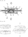
FIG. 2 is a cross-sectional view schematically illustrating a state before coupling a device for electrically connecting an electrode as an embodiment of the present invention. -
FIGS. 3 and 4 are a cross-sectional view and a perspective view schematically illustrating a state while coupling a device for electrically connecting an electrode as an embodiment of the present invention. -
FIGS. 5 and 6 are a cross-sectional view and a perspective view schematically illustrating an injection state of a sealing agent after coupling a device for electrically connecting an electrode as an embodiment of the present invention. -
FIG. 7 is a plan view and a bottom view of a state in which the device for electrically connecting the electrode as an embodiment of the present invention is fixed to the electrode. - Hereinafter, preferred embodiments of the present invention will be described in detail with reference to the accompanying drawings. Before describing the present invention, if it is determined that the detailed description of the related known functions and configurations may unnecessarily obscure the subject matter of the present invention, the description thereof will be omitted.
- The following description and drawings illustrate certain embodiments so that those skilled in the art can easily implement a device and a method to be described below. Other embodiments may include structurally and logically different modifications. Individual components and functions can generally be selected unless explicitly required, and the order of the processes can be varied. Portions and features of some embodiments may be included in or substituted with other embodiments.
- The present invention provides a device for electrically connecting an electrode as illustrated in
FIGS. 2 to 7 . That is, the electrically connecting device of the present invention includes an upperelectrode connection member 100 including anupper sealing cap 10 and one or moreconductive fixing nails 22 which are fixed to a lower surface of the sealing cap and connected to anelectrical wiring 24 withdrawn outward; and
a lower electrode connection member 100' including a lower sealing cap 10' and a conductive fixing nail fixing means 22' which is formed as a part of the sealing cap on the upper surface of the sealing cap or separately provided thereon,
wherein the lower surface of the upper sealingcap 10 includes asealing groove 12 which includes fixing portions of theconductive fixing nails 22 therein and includes one or more sealingagent injection hole 14 communicating with the upper surface of the upper sealing cap, and
the upper surface of the lower sealing cap 10' includes a sealing groove 12' which includes the conductive fixing nail fixing means 22' therein and includes one or more sealing agent injection hole 14' communicating with the lower surface of the lower sealing cap 10'. - As the materials of the
upper sealing cap 10 and the lower sealing cap 10', materials capable of sealing air and moisture may be used without limitation, and for example, a plastic material and the like as a polymer material may also be used. - The shapes of the
upper sealing cap 10 and the lower sealing cap 10' are not particularly limited, and for example, as illustrated inFIGS. 2 to 7 , a cylindrical shape may be used. - The
conductive fixing nail 22 may be generally formed of a conductive metal although the material thereof is not particularly limited so long as the material is a conductive material. - The conductive fixing nail fixing means 22' needs not to have conductivity and thus, an insulating material as well as the conductive material may also be used. For example, when the conductive fixing nail fixing means 22' is formed as a part of the lower sealing cap 10', the conductive fixing nail fixing means 22' may be formed of the same material as the lower sealing cap 10'.
- The
conductive fixing nail 22 may be in the form of a pin or a screw.FIGS. 2 to 7 illustrate the pin-shapedconductive fixing nails 22. - When the
conductive fixing nail 22 is in the form of a pin, as illustrated inFIGS. 3 to 6 , a tip of the pin-shaped fixing nail 22 may be bent by pressing. - The conductive fixing nail fixing means 22' may have a structure for fixing the
fixing nail 22, which is bent by pressing, a structure for forming a locking jaw for thefixing nail 22, or a structure for fixing the fixing nail by forming friction with thefixing nail 22, as illustrated inFIGS. 2 to 6 . - The
sealing groove 12 of the lower surface of theupper sealing cap 10 and the sealing groove 12' of the upper surface of the lower sealing cap 10' may seal inner spaces of thesealing grooves 12 and 12' of theupper sealing cap 10 and the lower sealing cap 10' by forming gapless binding between the upper and lower surfaces of the electrode by injecting thesealing agent 40. - As the
sealing agent 40, a sealing agent commonly used in the art may be used, and for example, a sealing agent such as a sealant may be used. - More specifically, as illustrated in
FIGS. 2 to 7 , the electrically connecting device of the present invention may have a structure in which the upperelectrode connection member 100 further includes aconductive plate 20 which has theconductive fixing nail 22 fixed to the lower surface thereof and is connected to theelectrical wiring 24 withdrawn outward. - Further, the lower electrode connection member 100' may further include a fixing plate 20' which has the conductive fixing nail fixing means 22' provided on the upper surface thereof.
- In this case, the sealing
groove 12 of theupper sealing cap 10 may be a ring-shapedgroove 12 which is spaced apart from an outer circumference of theconductive plate 20. - The sealing groove 12' of the lower sealing cap 10' may be a ring-shaped groove 12' which is spaced apart from an outer circumference of the fixing plate 20'.
- In the electrically connecting device of the present invention, as illustrated in
FIGS. 1 to 6 , theelectrode 30 may be an electrode in which an upper surface and a lower surface of anelectrode material 32 are sealed with aprotective member 34 and theelectrode 30 may be a flexible electrode. - Further, the present invention provides a flexible electrode having an electrical connection part formed by using the device for electrically connecting the electrode.
- The flexible electrode may be preferably used because the flexible electrode provides excellent electrical contact, excellent sealing, and excellent appearance.
- Further, the present invention relates to a method for electrically connecting an electrode using the device for electrically connecting the electrode of the present invention, the method comprising:
- positioning an
electrode 30 between an upperelectrode connection member 100 and a lower electrode connection member 100', as illustrated inFIG. 2 ; - fixing a conductive fixing
nail 22 fixed to a lower surface of anupper sealing cap 10 to a conductive fixing nail fixing means 22' provided on an upper surface of theupper sealing cap 10 through theelectrode 30 by pressing the upperelectrode connection member 100 and the lower electrode connection member 100', as illustrated inFIGS. 3 and 4 ; - performing filling a sealing
agent 40 in a sealinggroove 12 by injecting the sealingagent 40 into a sealingagent injection hole 14 provided in theupper sealing cap 10 and filling a sealingagent 40 in a sealing groove 12' by injecting the sealingagent 40 into a sealing agent injection hole 14' provided in the lower sealing cap 10' in random order, as illustrated inFIGS. 5 and 6 ; and - curing the sealing
agent 40 injected in the sealinggrooves 12 and 12'. - In the method for electrically connecting the electrode, all the contents described in the device for electrically connecting the electrode may be applied in the same manner.
- Although the present invention has been described in connection with the preferred embodiments mentioned above, it is possible to make various modifications or variations without departing from the spirit and scope of the invention. Therefore, the appended claims will include such modifications or variations as long as being included within the spirit of the present invention.
[Explanation of Numeral References and Symbols] 10: Upper sealing cap 12, 12': Sealing groove 14, 14': Sealing agent injection hole 20: Conductive plate 20': Fixing plate 22: Conductive fixing nail 22': Conductive fixing nail fixing means 24: Electrical wiring 30: Electrode 32: Electrode material 34: Protective layer 40: Sealing agent 50: Sealing agent injection device
Claims (15)
- A device for electrically connecting an electrode comprising:an upper electrode connection member including an upper sealing cap and one or more conductive fixing nails which are fixed to a lower surface of the sealing cap and connected to an electrical wiring withdrawn outward; anda lower electrode connection member including a lower sealing cap and a conductive fixing nail fixing means which is formed as a part of the sealing cap on the upper surface of the sealing cap or separately provided thereon,wherein the lower surface of the upper sealing cap includes a sealing groove which includes fixing portions of the conductive fixing nails therein and includes one or more sealing agent injection hole communicating with the upper surface of the upper sealing cap, andthe upper surface of the lower sealing cap includes a sealing groove which includes the conductive fixing nail fixing means therein and includes one or more sealing agent injection hole communicating with the lower surface of the lower sealing cap.
- The device for electrically connecting the electrode of claim 1, wherein the upper sealing cap and the lower sealing cap are formed of polymer materials.
- The device for electrically connecting the electrode of claim 1, wherein the conductive fixing nail is formed of a conductive metal.
- The device for electrically connecting the electrode of claim 1, wherein the conductive fixing nail is in the form of a pin or a screw.
- The device for electrically connecting the electrode of claim 1, wherein when the conductive fixing nail is in the form of a pin, a tip of the pin-shaped fixing nail is bent by pressing.
- The device for electrically connecting the electrode of claim 1, wherein the conductive fixing nail fixing means has a structure for fixing the fixing nail which is bent by pressing, a structure for forming a locking jaw for the fixing nail, or a structure for fixing the fixing nail by forming friction with the fixing nail.
- The device for electrically connecting the electrode of claim 1, wherein the sealing groove of the lower surface of the upper sealing cap and the sealing groove of the upper surface of the lower sealing cap seal inner spaces of the sealing grooves of the upper sealing cap and the lower sealing cap by forming gapless binding between the upper and lower surfaces of the electrode by injecting the sealing agent.
- The device for electrically connecting the electrode of claim 1, wherein the upper electrode connection member further includes a conductive plate which has the conductive fixing nail fixed to the lower surface thereof and is connected to the electrical wiring withdrawn outward.
- The device for electrically connecting the electrode of claim 1, wherein the lower electrode connection member further includes a fixing plate which has the conductive fixing nail fixing means provided on the upper surface thereof.
- The device for electrically connecting the electrode of claim 8, wherein the sealing groove is a ring-shaped groove which is spaced apart from an outer circumference of the conductive plate.
- The device for electrically connecting the electrode of claim 9, wherein the sealing groove is a ring-shaped groove which is spaced apart from an outer circumference of the fixing plate.
- The device for electrically connecting the electrode of claim 1, wherein the electrode is an electrode in which an upper surface and a lower surface of an electrode material are sealed with a protective member.
- The device for electrically connecting the electrode of claim 12, wherein the electrode is a flexible electrode.
- A flexible electrode having an electrical connection part formed by using the device for electrically connecting the electrode of claim 1.
- A method for electrically connecting an electrode using the device for electrically connecting the electrode of claim 1, the method comprising:positioning an electrode between an upper electrode connection member and a lower electrode connection member;fixing a conductive fixing nail fixed to a lower surface of an upper sealing cap to a conductive fixing nail fixing means provided on an upper surface of an upper sealing cap through the electrode by pressing the upper electrode connection member and the lower electrode connection member;performing filling a sealing agent in a sealing groove by injecting the sealing agent into a sealing agent injection hole provided in the upper sealing cap and filling a sealing agent in a sealing groove by injecting the sealing agent into a sealing agent injection hole provided in the lower sealing cap in random order; andcuring the sealing agent injected in the sealing grooves.
Applications Claiming Priority (2)
| Application Number | Priority Date | Filing Date | Title |
|---|---|---|---|
| KR1020170181582A KR20190079401A (en) | 2017-12-27 | 2017-12-27 | Appratus for electronical connection of an electrode and a flexible electrode forming electronical connection part using the same and method for electronically connecting an electrod using the same |
| PCT/KR2018/016670 WO2019132514A1 (en) | 2017-12-27 | 2018-12-26 | Device for electrically connecting electrode, flexible electrode having electrical connection part formed by using same, and method for electrically connecting electrode by using same |
Publications (2)
| Publication Number | Publication Date |
|---|---|
| EP3734619A1 true EP3734619A1 (en) | 2020-11-04 |
| EP3734619A4 EP3734619A4 (en) | 2021-09-29 |
Family
ID=67067796
Family Applications (1)
| Application Number | Title | Priority Date | Filing Date |
|---|---|---|---|
| EP18894443.3A Withdrawn EP3734619A4 (en) | 2017-12-27 | 2018-12-26 | Device for electrically connecting electrode, flexible electrode having electrical connection part formed by using same, and method for electrically connecting electrode by using same |
Country Status (3)
| Country | Link |
|---|---|
| EP (1) | EP3734619A4 (en) |
| KR (1) | KR20190079401A (en) |
| WO (1) | WO2019132514A1 (en) |
Family Cites Families (10)
| Publication number | Priority date | Publication date | Assignee | Title |
|---|---|---|---|---|
| DE19618998C1 (en) * | 1996-05-10 | 1998-01-02 | Siemens Ag | Contacting device |
| KR19980021522A (en) * | 1996-09-17 | 1998-06-25 | 이우복 | Field emission display device and manufacturing method thereof |
| DE10135311A1 (en) * | 2001-07-19 | 2003-03-06 | Nexans | Arrangement for connecting an electrical consumer to a supply line |
| JP2003282613A (en) * | 2002-03-20 | 2003-10-03 | Mitsubishi Electric Corp | Semiconductor device manufacturing method and resin sealing device |
| CN102349197B (en) * | 2009-01-14 | 2014-09-03 | 莫列斯公司 | Weather-resistant cable connector, electrical modules and weather-resistant assemblies thereof |
| DE102012000079B4 (en) * | 2012-01-04 | 2024-08-14 | Phoenix Contact Gmbh & Co. Kg | Electrical mandrel connector and its use |
| KR20130123236A (en) | 2012-05-02 | 2013-11-12 | 포항공과대학교 산학협력단 | Transparent electrode, flexible organic light emitting diode with the same and manufacturing method thereof |
| KR102244961B1 (en) * | 2013-03-14 | 2021-04-27 | 맥스웰 테크놀러지스 인코포레이티드 | Electrode graphite film and electrode divider ring for an energy storage device |
| KR101600170B1 (en) * | 2014-03-03 | 2016-03-07 | 하이디스 테크놀로지 주식회사 | Sealant injection apparatus |
| KR20170038473A (en) * | 2015-09-30 | 2017-04-07 | 코오롱인더스트리 주식회사 | Organic photovoltaic module, encapsulation apparatus and method of the same |
-
2017
- 2017-12-27 KR KR1020170181582A patent/KR20190079401A/en not_active Abandoned
-
2018
- 2018-12-26 WO PCT/KR2018/016670 patent/WO2019132514A1/en not_active Ceased
- 2018-12-26 EP EP18894443.3A patent/EP3734619A4/en not_active Withdrawn
Also Published As
| Publication number | Publication date |
|---|---|
| WO2019132514A1 (en) | 2019-07-04 |
| KR20190079401A (en) | 2019-07-05 |
| EP3734619A4 (en) | 2021-09-29 |
Similar Documents
| Publication | Publication Date | Title |
|---|---|---|
| US9017088B2 (en) | Electric connector | |
| US20170238446A1 (en) | Display panel and display device | |
| US20160104863A1 (en) | Display device and manufacturing method thereof | |
| WO2008155925A1 (en) | Display device and electrical equipment utilizing the same | |
| WO2004015441A3 (en) | Radio frequency identificaton device and method | |
| KR20150098284A (en) | Organic light emitting display apparatus | |
| WO2010032946A3 (en) | Alignment material, alignment layer, liquid crystal display device and manufacturing method thereof | |
| TW200518241A (en) | Device having a compliant element pressed between substrates | |
| KR101751044B1 (en) | Organic light emitting display panel and method for manufacturing the same | |
| US20170099744A1 (en) | Method for making multi-part frame | |
| TW200729625A (en) | Memory card adaptor | |
| EP2624371A3 (en) | Hermetic feed-through with hybrid seal structure | |
| US10429898B2 (en) | Electronic device | |
| EP1744268A3 (en) | RFID tag and manufacturing method thereof | |
| EP1811590A3 (en) | Organic light-emitting display and method of making the same | |
| WO2009022461A1 (en) | Circuit device, circuit device manufacturing method and portable device | |
| EP3252812A3 (en) | Embedded package structure | |
| WO2007130729A3 (en) | Method of forming a semiconductor device and structure thereof | |
| TW200729561A (en) | Luminescence device and manufacturing method of the same | |
| US20150023754A1 (en) | Nut structure for connecting structure | |
| EP1624489A3 (en) | Flat panel display device with reduced cross-talk | |
| WO2008133037A1 (en) | Electrically conductive particle, anisotropic conductive connection material, and method for production of electrically conductive particle | |
| TW200636782A (en) | Solid electrolytic capacitor and manufacturing method thereof | |
| US9596748B2 (en) | Lens mount with conductive glue pocket for grounding to a circuit board | |
| WO2012058011A3 (en) | Interconnect structure with enhanced reliability |
Legal Events
| Date | Code | Title | Description |
|---|---|---|---|
| STAA | Information on the status of an ep patent application or granted ep patent |
Free format text: STATUS: THE INTERNATIONAL PUBLICATION HAS BEEN MADE |
|
| PUAI | Public reference made under article 153(3) epc to a published international application that has entered the european phase |
Free format text: ORIGINAL CODE: 0009012 |
|
| STAA | Information on the status of an ep patent application or granted ep patent |
Free format text: STATUS: REQUEST FOR EXAMINATION WAS MADE |
|
| 17P | Request for examination filed |
Effective date: 20200630 |
|
| AK | Designated contracting states |
Kind code of ref document: A1 Designated state(s): AL AT BE BG CH CY CZ DE DK EE ES FI FR GB GR HR HU IE IS IT LI LT LU LV MC MK MT NL NO PL PT RO RS SE SI SK SM TR |
|
| AX | Request for extension of the european patent |
Extension state: BA ME |
|
| DAV | Request for validation of the european patent (deleted) | ||
| DAX | Request for extension of the european patent (deleted) | ||
| STAA | Information on the status of an ep patent application or granted ep patent |
Free format text: STATUS: THE APPLICATION HAS BEEN WITHDRAWN |
|
| A4 | Supplementary search report drawn up and despatched |
Effective date: 20210826 |
|
| RIC1 | Information provided on ipc code assigned before grant |
Ipc: H01R 12/68 20110101ALI20210820BHEP Ipc: H05K 3/32 20060101ALI20210820BHEP Ipc: H01R 12/61 20110101AFI20210820BHEP |
|
| 18W | Application withdrawn |
Effective date: 20210917 |