EP3734591B1 - Musical sound effect adding device and musical sound effect adding program - Google Patents
Musical sound effect adding device and musical sound effect adding program Download PDFInfo
- Publication number
- EP3734591B1 EP3734591B1 EP17935961.7A EP17935961A EP3734591B1 EP 3734591 B1 EP3734591 B1 EP 3734591B1 EP 17935961 A EP17935961 A EP 17935961A EP 3734591 B1 EP3734591 B1 EP 3734591B1
- Authority
- EP
- European Patent Office
- Prior art keywords
- pitch
- musical sound
- effect
- sound effect
- effect adding
- Prior art date
- Legal status (The legal status is an assumption and is not a legal conclusion. Google has not performed a legal analysis and makes no representation as to the accuracy of the status listed.)
- Active
Links
Images


Classifications
-
- G—PHYSICS
- G10—MUSICAL INSTRUMENTS; ACOUSTICS
- G10H—ELECTROPHONIC MUSICAL INSTRUMENTS; INSTRUMENTS IN WHICH THE TONES ARE GENERATED BY ELECTROMECHANICAL MEANS OR ELECTRONIC GENERATORS, OR IN WHICH THE TONES ARE SYNTHESISED FROM A DATA STORE
- G10H1/00—Details of electrophonic musical instruments
- G10H1/36—Accompaniment arrangements
- G10H1/40—Rhythm
- G10H1/42—Rhythm comprising tone forming circuits
-
- G—PHYSICS
- G10—MUSICAL INSTRUMENTS; ACOUSTICS
- G10H—ELECTROPHONIC MUSICAL INSTRUMENTS; INSTRUMENTS IN WHICH THE TONES ARE GENERATED BY ELECTROMECHANICAL MEANS OR ELECTRONIC GENERATORS, OR IN WHICH THE TONES ARE SYNTHESISED FROM A DATA STORE
- G10H1/00—Details of electrophonic musical instruments
- G10H1/02—Means for controlling the tone frequencies, e.g. attack or decay; Means for producing special musical effects, e.g. vibratos or glissandos
- G10H1/04—Means for controlling the tone frequencies, e.g. attack or decay; Means for producing special musical effects, e.g. vibratos or glissandos by additional modulation
- G10H1/043—Continuous modulation
-
- G—PHYSICS
- G10—MUSICAL INSTRUMENTS; ACOUSTICS
- G10H—ELECTROPHONIC MUSICAL INSTRUMENTS; INSTRUMENTS IN WHICH THE TONES ARE GENERATED BY ELECTROMECHANICAL MEANS OR ELECTRONIC GENERATORS, OR IN WHICH THE TONES ARE SYNTHESISED FROM A DATA STORE
- G10H1/00—Details of electrophonic musical instruments
- G10H1/02—Means for controlling the tone frequencies, e.g. attack or decay; Means for producing special musical effects, e.g. vibratos or glissandos
- G10H1/04—Means for controlling the tone frequencies, e.g. attack or decay; Means for producing special musical effects, e.g. vibratos or glissandos by additional modulation
- G10H1/053—Means for controlling the tone frequencies, e.g. attack or decay; Means for producing special musical effects, e.g. vibratos or glissandos by additional modulation during execution only
-
- G—PHYSICS
- G10—MUSICAL INSTRUMENTS; ACOUSTICS
- G10H—ELECTROPHONIC MUSICAL INSTRUMENTS; INSTRUMENTS IN WHICH THE TONES ARE GENERATED BY ELECTROMECHANICAL MEANS OR ELECTRONIC GENERATORS, OR IN WHICH THE TONES ARE SYNTHESISED FROM A DATA STORE
- G10H1/00—Details of electrophonic musical instruments
- G10H1/02—Means for controlling the tone frequencies, e.g. attack or decay; Means for producing special musical effects, e.g. vibratos or glissandos
- G10H1/04—Means for controlling the tone frequencies, e.g. attack or decay; Means for producing special musical effects, e.g. vibratos or glissandos by additional modulation
- G10H1/053—Means for controlling the tone frequencies, e.g. attack or decay; Means for producing special musical effects, e.g. vibratos or glissandos by additional modulation during execution only
- G10H1/057—Means for controlling the tone frequencies, e.g. attack or decay; Means for producing special musical effects, e.g. vibratos or glissandos by additional modulation during execution only by envelope-forming circuits
-
- G—PHYSICS
- G10—MUSICAL INSTRUMENTS; ACOUSTICS
- G10H—ELECTROPHONIC MUSICAL INSTRUMENTS; INSTRUMENTS IN WHICH THE TONES ARE GENERATED BY ELECTROMECHANICAL MEANS OR ELECTRONIC GENERATORS, OR IN WHICH THE TONES ARE SYNTHESISED FROM A DATA STORE
- G10H1/00—Details of electrophonic musical instruments
- G10H1/02—Means for controlling the tone frequencies, e.g. attack or decay; Means for producing special musical effects, e.g. vibratos or glissandos
- G10H1/06—Circuits for establishing the harmonic content of tones, or other arrangements for changing the tone colour
- G10H1/08—Circuits for establishing the harmonic content of tones, or other arrangements for changing the tone colour by combining tones
- G10H1/10—Circuits for establishing the harmonic content of tones, or other arrangements for changing the tone colour by combining tones for obtaining chorus, celeste or ensemble effects
-
- G—PHYSICS
- G10—MUSICAL INSTRUMENTS; ACOUSTICS
- G10H—ELECTROPHONIC MUSICAL INSTRUMENTS; INSTRUMENTS IN WHICH THE TONES ARE GENERATED BY ELECTROMECHANICAL MEANS OR ELECTRONIC GENERATORS, OR IN WHICH THE TONES ARE SYNTHESISED FROM A DATA STORE
- G10H2210/00—Aspects or methods of musical processing having intrinsic musical character, i.e. involving musical theory or musical parameters or relying on musical knowledge, as applied in electrophonic musical tools or instruments
- G10H2210/155—Musical effects
- G10H2210/195—Modulation effects, i.e. smooth non-discontinuous variations over a time interval, e.g. within a note, melody or musical transition, of any sound parameter, e.g. amplitude, pitch, spectral response or playback speed
- G10H2210/221—Glissando, i.e. pitch smoothly sliding from one note to another, e.g. gliss, glide, slide, bend, smear or sweep
- G10H2210/225—Portamento, i.e. smooth continuously variable pitch-bend, without emphasis of each chromatic pitch during the pitch change, which only stops at the end of the pitch shift, as obtained, e.g. by a MIDI pitch wheel or trombone
-
- G—PHYSICS
- G10—MUSICAL INSTRUMENTS; ACOUSTICS
- G10H—ELECTROPHONIC MUSICAL INSTRUMENTS; INSTRUMENTS IN WHICH THE TONES ARE GENERATED BY ELECTROMECHANICAL MEANS OR ELECTRONIC GENERATORS, OR IN WHICH THE TONES ARE SYNTHESISED FROM A DATA STORE
- G10H2210/00—Aspects or methods of musical processing having intrinsic musical character, i.e. involving musical theory or musical parameters or relying on musical knowledge, as applied in electrophonic musical tools or instruments
- G10H2210/155—Musical effects
- G10H2210/321—Missing fundamental, i.e. creating the psychoacoustic impression of a missing fundamental tone through synthesis of higher harmonics, e.g. to play bass notes pitched below the frequency range of reproducing speakers
-
- G—PHYSICS
- G10—MUSICAL INSTRUMENTS; ACOUSTICS
- G10H—ELECTROPHONIC MUSICAL INSTRUMENTS; INSTRUMENTS IN WHICH THE TONES ARE GENERATED BY ELECTROMECHANICAL MEANS OR ELECTRONIC GENERATORS, OR IN WHICH THE TONES ARE SYNTHESISED FROM A DATA STORE
- G10H2250/00—Aspects of algorithms or signal processing methods without intrinsic musical character, yet specifically adapted for or used in electrophonic musical processing
- G10H2250/025—Envelope processing of music signals in, e.g. time domain, transform domain or cepstrum domain
- G10H2250/035—Crossfade, i.e. time domain amplitude envelope control of the transition between musical sounds or melodies, obtained for musical purposes, e.g. for ADSR tone generation, articulations, medley, remix
Definitions
- the present invention relates to a musical sound effect adding device and a musical sound effect adding program.
- a flanger using delay time modulation, a phaser using phase amount modulation, and the like have been known as devices that add a musical effect to a musical sound signal.
- Patent Literature 1 discloses a device that generates an infinite scale.
- the musical sound effect adding device according to Patent Literature 1 includes a pitch shifter group, a phase shift group, and an adder.
- a plurality of pitch shifters that constitute the pitch shifter group each perform pitch shift to an externally supplied musical sound signal by a predetermined shift amount
- a plurality of phase shifters that constitute the phase shift group each phase-delay an oscillation signal in increments of a predetermined phase amount
- the adder adds pitch shift signals from all the pitch shifters.
- a delay amount of the phase-delayed signal to be provided to each of the pitch shifters is increased in increments of a predetermined phase amount per pitch shifter, thereby achieving an effect of giving a pitch ascending or descending feeling even to an external musical sound signal.
- Patent Literature 1 JP 4678871 B
- Patent Literature 1 is, however, disadvantageous in that in again shifting from a lower limit of a pitch amount after a pitch shift amount of any one of the pitch shifters reaches an upper limit, a rapid change in the signal causes a discontinuous change in a pitch shift sound.
- Patent Literature 1 it is proposed that a waveform converter is provided to multiply a pitch shift signal by a trapezoidal wave to reduce discontinuity in a case of transition from the upper limit to the lower limit, but such a method disadvantageously necessitates complication of a process for adding an effect.
- An object of the invention is to provide a musical sound effect adding device and a musical sound effect adding program that allow for adding an infinite scale effect without the necessity of performing a complicated process.
- a musical sound effect according to appended claim 1 is provided.
- a musical sound effect adding program is configured to enable a computer to function as the above-described musical sound effect adding device.
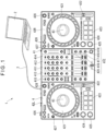
- Fig. 1 shows a music piece reproduction control system 1 according to the exemplary embodiment of the invention.
- the music piece data reproduction control system 1 includes a computer 2 and a DJ controller 4 connected to the computer 2 through a USB cable 3.
- the computer 2 which includes a CPU and a storage such as a hard disk, is configured to reproduce music piece data such as MP3 stored in the storage.
- the music piece data is reproduced by software run on the CPU and the reproduced music piece data is outputted to the DJ controller 4 through the USB cable 3. Further, a reproduction control signal generated by operating a mixer 41 and decks 42L and 42R of the DJ controller 4 is outputted to the USB cable 3 to be inputted to the computer 2.
- a variety of sound effects are added to the currently reproduced music piece data on the basis of the reproduction control signal outputted from the DJ controller 4.
- the DJ controller 4 which is an example of sound equipment, includes the mixer 41 located at a center thereof and the decks 42L and 42R located at right and left of the mixer 41. It is to be noted that the sound equipment according to the invention is a concept including not only a sound reproduction controller as in the exemplary embodiment but also a sound reproducer configured to reproduce music piece data.
- the mixer 41 which is a section configured to switch audio data outputted from the computer 2, adjust volumes of channels, and add a sound effect, includes first channel adjuster 411 to fourth channel adjuster 414 and a microphone adjuster 415.
- An effector 41E is provided at a lower right of the mixer 41.
- the effector 41E includes an effect selection switch 416, a channel selection switch 417, an effect-amount adjusting switch 418, an effect adding switch 419, and a beat changing switch 420 as described later in detail.
- the decks 42L and 42R which are sections configured to be operated by an operator to add a variety of effects to music piece data outputted from the computer 2, each include a jog dial 421, a tempo slider 422, a performance pad 423, a CUE button 424, a play/pause button 425, a loop button 426, a deck selection button 427, and a load button 428.
- the jog dial 421 which is an example of a rotary operation unit, is rotatably provided to a device body of each of the decks 42L and 42R, is configured to fast-forward and reverse music piece data to be reproduced when the operator rotates the jog dial 421.
- a display 43 which includes a liquid crystal display, is provided at a center of the jog dial 421.
- a BPM (Beats Per Minute) value, an elapsed time, a state of progress, and a beat position of the currently reproduced music piece data, and a state of rotation of an LP record at 33 RPM with the progress of the currently reproduced music piece data are displayed on the display 43, allowing the operator to see the progress of the reproduction of the music piece data.
- BPM Beats Per Minute
- the tempo slider 422 is a switch for adjusting a tempo of music piece data to be reproduced.
- the performance pad 423 which is a button for switching an effect for the currently reproduced music piece data, is configured to add effects, such as loop, cue, slicer, and sampler, to the currently reproduced music piece data instantaneously when the performance pad 423 is pressed by the operator.
- the CUE button 424 is a button for cuing music piece to be reproduced.
- the play/pause button 425 is a button for starting reproduction of music piece data and pausing the currently reproduced music piece data.
- the loop button 426 is a button for performing loop reproduction of the currently reproduced music piece data.
- the deck selection button 427 is a button for selecting one of the first channel adjuster 411 to the fourth channel adjuster 414 of the mixer 41 that is to be used for operating the currently reproduced music piece data.
- the left deck 42L is configured to switch between the first channel adjuster 411 and the third channel adjuster 413 and the right deck 42R is configured to switch between the second channel adjuster 412 and the fourth channel adjuster 414.
- the load button 428 is a button for loading music piece data from the computer 2. By pressing the load button 428 after music piece data to be reproduced is selected on the computer 2, the music piece data is loaded to a channel of one of the first channel adjuster 411 to the fourth channel adjuster 414.
- the DJ controller 4 is configured to add an effect to a musical sound signal that constitutes the music piece data. Specifically, an effect can be added to the musical sound signal of the music piece data by operating the effector 41E located at the lower right of the mixer 41 as shown in Fig. 2 .
- the effect selection switch 416 is a switch for selecting an effect to be added to the musical sound signal. Examples of the effect include echo, delay, reverb, flanger, phaser, pitch, and noise, which can be selected also in a later-described musical sound effect adding device 5 by operating the effect selection switch 416.
- the channel selection switch 417 which is a switch for selecting a channel where an effect is to be added, allows for adding an effect to the first channel adjuster 411 to the fourth channel adjuster 414 and the microphone adjuster 415 of the effector 41E.
- the effect-amount adjusting switch 418 which is a switch for adjusting a of a musical sound effect to be added to an original sound of the music piece data, allows for setting the magnitude of the effect through volume adjustment.
- the effect adding switch 419 which is a switch for adding an effect synchronized with a beat position or BPM of the musical sound signal, is configured to apply the effect selected with the effect selection switch 416 to the channel selected with the channel selection switch.
- the beat changing switch 420 which is a switch for adding an effect synchronized with the beat position or BPM of the musical sound signal, includes a right direction arrow button that is to be operated to increase beat magnification and a left direction arrow button that is to be operated to reduce the beat magnification.
- Fig. 3 shows the musical sound effect adding device 5 according to the exemplary embodiment of the invention.
- the musical sound effect adding device 5 is an effector configured to generate and output a sawtooth wave, a triangular wave, a sine wave, a rectangular wave, or the like, which sounds such that a pitch continuously ascends or descends in accordance with a beat of currently reproduced music piece data SD.
- the musical sound effect adding device 5 includes an LFO (Low Frequency Oscillator) 51, parallel-connected four oscillators 521 to 524, respective faders 53, respective adders 54, and a level adjuster 55, which constitute a musical sound effect adding program to be run on the CPU of the DJ controller 4.
- LFO Low Frequency Oscillator
- the LFO 51 is configured to output a periodic signal in a form of a low-frequency wave to each of the oscillators 521 to 524 and the faders 53.
- the LFO 51 is configured to read beat position information from the inputted music piece data SD and output a periodic signal synchronized with an n-beat or 1/n-beat (n: integer) cycle of the musical sound signal to each of the oscillators 521 to 524 and the faders 53.
- the LFO 51 functions as a periodic signal generator according to the invention.
- the LFO 51 is configured to output pitch shift signals that are mutually different in an output start pitch to the respective oscillators 521 to 524, the pitch shift signals each being contained in the periodic signal.
- the LFO 51 is configured to output a pitch shift signal at a certain pitch to the oscillator 521 of a first tier, output a pitch shift signal that is two octave higher than the pitch at a start of the output to the oscillator 521 of the first tier to the oscillator 522 of the second tier, output a pitch shift signal that is four octave higher than the pitch at the start of the output to the oscillator 521 of the first tier to the oscillator 523 of the third tier, and output a pitch shift signal that is six octave higher than the pitch at the start of the output to the oscillator 521 of the first tier to the oscillator 524 of the fourth tier.
- the LFO 51 functions as a pitch shift section according to the invention.
- the oscillators 521 to 524 which exemplify an acoustic signal generator, are each configured to generate an effect sound, that is, an acoustic signal with a pitch continuously shifted on an octave basis, in synchronization with the periodic signal outputted from the LFO 51.
- the oscillators 521 to 524 can generate effect sounds in a range of seven octaves of 55 Hz to 7040 Hz.
- the oscillators 521 to 524 are respectively configured to output the effect sounds shifting in an ascending direction from the start, and when the effect sounds exceed an upper limit one of the octaves, reset the effect sounds to a lower limit one of the octaves, and again output the effect sounds with a continuously ascending pitch.
- the faders 53 are each configured to fade out the effect sound when the pitch of the acoustic signal generated by corresponding one of the oscillators 521 to 524 reaches a first pitch and fade in the effect sound when the pitch reaches a second pitch.
- the faders 53 are each configured to fade in the effect sound in the lower limit octave (55 Hz to 110 Hz) that can be outputted by the oscillators 521 to 524 and fade out the effect sound in the upper limit octave (3520 Hz to 7040 Hz) that can be outputted by the oscillators 521 to 524, thereby allowing for generating an infinite scale effect sound.
- the plurality of adders 54 are sections for superimposing the respective effect sounds generated by the oscillators 521 to 524.
- the acoustic signals superimposed by the adders 54 are outputted to the level adjuster 55.
- the level adjuster 55 which is a section for superimposing the effect sounds generated by the musical sound effect adding device 5 at a desired percentage relative to a volume of the original sound in accordance with an operation by a user, is configured to adjust the effect sounds through the operation of the effect-amount adjusting switch 418 of the above-described switch group. Specifically, as shown in Fig. 4 , the volume of the effect sounds is adjusted while the volume of the original sound is kept at 100%. In the exemplary embodiment, the effect sounds are adjustable from - ⁇ via -16.5 dB to -3.67 dB.
- the effect sound adjusted by the level adjuster 55 is outputted from the mixer 41 along with the original sound.
- a pitch shift signal that starts from the lowest pitch of 55 Hz is outputted to the oscillator 521 of the first tier, and a pitch shift signal that is two octave higher than the pitch shift signal outputted to the oscillator 521 of the first tier is outputted to the oscillator 522 of the second tier as shown in Fig. 5 .
- a pitch shift signal that is four octave higher than the pitch shift signal outputted to the oscillator of the first tier is outputted to the oscillator 523 of the third tier
- a pitch shift signal that is six octave higher than the pitch shift signal outputted to the oscillator of the first tier is outputted to the oscillator 524 of the third tier.
- the effect sound outputted from each of the oscillators 521 to 524 is faded in in the lowest one octave (from 55 Hz to 110 Hz) and faded out in the highest one octave (from 3520 Hz to 7040 Hz).
- the sound effect adding device 5 generates such an effect sound, thereby making it possible to output an infinite scale effect sound with an ascending pitch in accordance with a tempo of the currently reproduced music piece data SD.
- the use of the musical sound effect adding device 5 makes it possible to add an infinite scale effect in accordance with a reproduction tempo of the music piece data SD without the necessity of performing a complicated process.
- the effect sound generated by each of the oscillators 521 to 524 of the musical sound effect adding device 5 is an acoustic signal in a form of a sawtooth wave, a listener can feel the effect sound ascending indefinitely.
- a triangular wave, a sine wave, or a rectangular wave is usable in place of the sawtooth wave.
- the musical sound effect adding device 5 is configured to fade in the effect sound in one octave near the lowest pitch when the pitch of the acoustic signal outputted from each of the oscillators 521 to 524 reaches the first pitch, that is, 55 Hz, and fade out the effect sound in one octave near the highest pitch when the pitch reaches the second pitch, that is, 3520 Hz. This can make the effect sound unnoticeable to a listener when each of the oscillators 521 to 524 switches from the high pitch to the low pitch, allowing the listener to further feel the infinite scale.
- the pitch shift signal outputted from the LFO 51 is a pitch shift signal that shifts a pitch on the octave basis, so that the effect sounds outputted from the oscillator 521-524 are always offset from each other on the octave basis. Therefore, the effect sounds outputted from the oscillators 521 to 524 are added by the adders 54 without making a discord, allowing the listener to feel a comfortable effect sound.
- the musical sound effect adding device 5 includes the four oscillators 521 to 524; however, the invention is not limited thereto.
- the musical sound effect adding device only needs to include a plurality of oscillators and includes more than two oscillators in some embodiments.
- the oscillators 521 to 524 are each configured to output the effect sound in seven octaves; however, the invention is not limited thereto.
- An oscillator configured to output an effect sound exceeding seven octaves may be employed the acoustic signal generator.
- the musical sound effect adding device 5 is configured to output the infinite scale effect sound with an ascending pitch; however, the invention is not limited thereto.
- the musical sound effect adding device 5 may be configured to output an infinite scale effect sound with a descending pitch in some embodiments.
- the musical sound effect adding device 5 can output an infinite scale sound with a descending pitch by a sawtooth wave descending to the right, which is the inverse of the sawtooth wave shown in Fig. 5 .
- the LFO 51 that is, the pitch shift section, is configured to output the pitch shift signal to be outputted to each of the oscillators 521 to 524 as a pitch shift signal shifting on the octave basis.
- a pitch shift signal shifted in pitch by a third interval is outputted to the oscillator.
- 1...music piece data reproduction control system 2...computer, 3...USB cable, 4...DJ controller, 5...musical sound effect adding device, 41...mixer, 41E...effector, 42L...deck, 42R...deck, 43...display, 51...LFO, 53...fader, 54...adder, 55...level adjuster, 411...first channel adjuster, 412...second channel adjuster, 413...third channel adjuster, 414...fourth channel adjuster, 415...microphone adjuster, 416...effect selection switch, 417...channel selection switch, 418...effect-amount adjusting switch, 419...effect adding switch, 420...beat changing switch, 421...jog dial, 422...tempo slider, 423...
- performance pad 424...CUE button, 425...play/pause button, 426...loop button, 427...deck selection button, 428...load button, 521...oscillator, 522...oscillator, 523...oscillator, 524...oscillator, SD...music piece data.
Landscapes
- Physics & Mathematics (AREA)
- Engineering & Computer Science (AREA)
- Acoustics & Sound (AREA)
- Multimedia (AREA)
- Electrophonic Musical Instruments (AREA)
Description
- The present invention relates to a musical sound effect adding device and a musical sound effect adding program.
- A flanger using delay time modulation, a phaser using phase amount modulation, and the like have been known as devices that add a musical effect to a musical sound signal.
- Regarding such a musical sound effect adding device, Patent Literature 1 discloses a device that generates an infinite scale. The musical sound effect adding device according to Patent Literature 1 includes a pitch shifter group, a phase shift group, and an adder.
- In this musical sound effect adding device, a plurality of pitch shifters that constitute the pitch shifter group each perform pitch shift to an externally supplied musical sound signal by a predetermined shift amount, a plurality of phase shifters that constitute the phase shift group each phase-delay an oscillation signal in increments of a predetermined phase amount, and the adder adds pitch shift signals from all the pitch shifters.
- Further, a delay amount of the phase-delayed signal to be provided to each of the pitch shifters is increased in increments of a predetermined phase amount per pitch shifter, thereby achieving an effect of giving a pitch ascending or descending feeling even to an external musical sound signal.
- Patent Literature 1:
JP 4678871 B - The technology of Patent Literature 1 is, however, disadvantageous in that in again shifting from a lower limit of a pitch amount after a pitch shift amount of any one of the pitch shifters reaches an upper limit, a rapid change in the signal causes a discontinuous change in a pitch shift sound.
- Accordingly, in the technology described in Patent Literature 1, it is proposed that a waveform converter is provided to multiply a pitch shift signal by a trapezoidal wave to reduce discontinuity in a case of transition from the upper limit to the lower limit, but such a method disadvantageously necessitates complication of a process for adding an effect.
- Video tutorial "Creating A Shepard's Tone Using Ableton Live Part 1", 17 February 2009 (2009-02-17), Internet:URL:https://www.youtube.com/watch?v=XLdxUsSAzDU, or BeatsbyVanityTV: "The Sound Illusion of the Shepard Tone - Lessons of Live Episode 01", 21 October 2017 (2017-10-21), Internet:URL:https:Hwww.youtube.com/watch?v=sc-Gr9yH8VA discuss creating Shepard's Tones using well known musical editing software.
- An object of the invention is to provide a musical sound effect adding device and a musical sound effect adding program that allow for adding an infinite scale effect without the necessity of performing a complicated process.
- A musical sound effect according to appended claim 1 is provided.
- A musical sound effect adding program according to another aspect of the invention is configured to enable a computer to function as the above-described musical sound effect adding device.
- In this aspect of the invention, it is also possible to achieve workings and effects similar to those described above.
-
-
Fig. 1 is a schematic diagram showing a music piece data reproduction control system according to an exemplary embodiment of the invention. -
Fig. 2 is a schematic diagram showing a switch group for operating a musical sound effect adding device according to the exemplary embodiment. -
Fig. 3 is a functional block diagram showing a structure of the musical sound effect adding device according to the exemplary embodiment. -
Fig. 4 is a graph showing volume adjustment of an original sound and an effect sound by a level adjuster according to the exemplary embodiment. -
Fig. 5 is a schematic diagram for explaining workings according to the exemplary embodiment. - An exemplary embodiment of the invention will be described below with reference to the drawings.
Fig. 1 shows a music piece reproduction control system 1 according to the exemplary embodiment of the invention. The music piece data reproduction control system 1 includes acomputer 2 and aDJ controller 4 connected to thecomputer 2 through aUSB cable 3. - The
computer 2, which includes a CPU and a storage such as a hard disk, is configured to reproduce music piece data such as MP3 stored in the storage. The music piece data is reproduced by software run on the CPU and the reproduced music piece data is outputted to theDJ controller 4 through theUSB cable 3. Further, a reproduction control signal generated by operating amixer 41 anddecks DJ controller 4 is outputted to theUSB cable 3 to be inputted to thecomputer 2. In thecomputer 2, a variety of sound effects are added to the currently reproduced music piece data on the basis of the reproduction control signal outputted from theDJ controller 4. - The
DJ controller 4, which is an example of sound equipment, includes themixer 41 located at a center thereof and thedecks mixer 41. It is to be noted that the sound equipment according to the invention is a concept including not only a sound reproduction controller as in the exemplary embodiment but also a sound reproducer configured to reproduce music piece data. - The
mixer 41, which is a section configured to switch audio data outputted from thecomputer 2, adjust volumes of channels, and add a sound effect, includesfirst channel adjuster 411 tofourth channel adjuster 414 and amicrophone adjuster 415. - An
effector 41E is provided at a lower right of themixer 41. To add a musical sound effect to a music piece to be reproduced, theeffector 41E includes aneffect selection switch 416, achannel selection switch 417, an effect-amount adjusting switch 418, aneffect adding switch 419, and abeat changing switch 420 as described later in detail. - The
decks computer 2, each include ajog dial 421, atempo slider 422, aperformance pad 423, aCUE button 424, a play/pause button 425, aloop button 426, adeck selection button 427, and aload button 428. - The
jog dial 421, which is an example of a rotary operation unit, is rotatably provided to a device body of each of thedecks jog dial 421. - A
display 43, which includes a liquid crystal display, is provided at a center of thejog dial 421. A BPM (Beats Per Minute) value, an elapsed time, a state of progress, and a beat position of the currently reproduced music piece data, and a state of rotation of an LP record at 33 RPM with the progress of the currently reproduced music piece data are displayed on thedisplay 43, allowing the operator to see the progress of the reproduction of the music piece data. - The
tempo slider 422 is a switch for adjusting a tempo of music piece data to be reproduced. Theperformance pad 423, which is a button for switching an effect for the currently reproduced music piece data, is configured to add effects, such as loop, cue, slicer, and sampler, to the currently reproduced music piece data instantaneously when theperformance pad 423 is pressed by the operator. - The
CUE button 424 is a button for cuing music piece to be reproduced. - The play/
pause button 425 is a button for starting reproduction of music piece data and pausing the currently reproduced music piece data. Theloop button 426 is a button for performing loop reproduction of the currently reproduced music piece data. - The
deck selection button 427 is a button for selecting one of thefirst channel adjuster 411 to thefourth channel adjuster 414 of themixer 41 that is to be used for operating the currently reproduced music piece data. In the exemplary embodiment, theleft deck 42L is configured to switch between thefirst channel adjuster 411 and thethird channel adjuster 413 and theright deck 42R is configured to switch between thesecond channel adjuster 412 and the fourth channel adjuster 414. - The
load button 428 is a button for loading music piece data from thecomputer 2. By pressing theload button 428 after music piece data to be reproduced is selected on thecomputer 2, the music piece data is loaded to a channel of one of thefirst channel adjuster 411 to thefourth channel adjuster 414. - The
DJ controller 4 is configured to add an effect to a musical sound signal that constitutes the music piece data. Specifically, an effect can be added to the musical sound signal of the music piece data by operating theeffector 41E located at the lower right of themixer 41 as shown inFig. 2 . - The
effect selection switch 416 is a switch for selecting an effect to be added to the musical sound signal. Examples of the effect include echo, delay, reverb, flanger, phaser, pitch, and noise, which can be selected also in a later-described musical soundeffect adding device 5 by operating theeffect selection switch 416. - The
channel selection switch 417, which is a switch for selecting a channel where an effect is to be added, allows for adding an effect to thefirst channel adjuster 411 to thefourth channel adjuster 414 and the microphone adjuster 415 of theeffector 41E. - The effect-
amount adjusting switch 418, which is a switch for adjusting a of a musical sound effect to be added to an original sound of the music piece data, allows for setting the magnitude of the effect through volume adjustment. - The
effect adding switch 419, which is a switch for adding an effect synchronized with a beat position or BPM of the musical sound signal, is configured to apply the effect selected with theeffect selection switch 416 to the channel selected with the channel selection switch. - The
beat changing switch 420, which is a switch for adding an effect synchronized with the beat position or BPM of the musical sound signal, includes a right direction arrow button that is to be operated to increase beat magnification and a left direction arrow button that is to be operated to reduce the beat magnification. -
Fig. 3 shows the musical soundeffect adding device 5 according to the exemplary embodiment of the invention. The musical soundeffect adding device 5 is an effector configured to generate and output a sawtooth wave, a triangular wave, a sine wave, a rectangular wave, or the like, which sounds such that a pitch continuously ascends or descends in accordance with a beat of currently reproduced music piece data SD. - The musical sound
effect adding device 5 includes an LFO (Low Frequency Oscillator) 51, parallel-connected fouroscillators 521 to 524,respective faders 53,respective adders 54, and alevel adjuster 55, which constitute a musical sound effect adding program to be run on the CPU of theDJ controller 4. - The LFO 51 is configured to output a periodic signal in a form of a low-frequency wave to each of the
oscillators 521 to 524 and thefaders 53. Specifically, theLFO 51 is configured to read beat position information from the inputted music piece data SD and output a periodic signal synchronized with an n-beat or 1/n-beat (n: integer) cycle of the musical sound signal to each of theoscillators 521 to 524 and thefaders 53. In other words, theLFO 51 functions as a periodic signal generator according to the invention. - Further, the
LFO 51 is configured to output pitch shift signals that are mutually different in an output start pitch to therespective oscillators 521 to 524, the pitch shift signals each being contained in the periodic signal. Specifically, theLFO 51 is configured to output a pitch shift signal at a certain pitch to theoscillator 521 of a first tier, output a pitch shift signal that is two octave higher than the pitch at a start of the output to theoscillator 521 of the first tier to theoscillator 522 of the second tier, output a pitch shift signal that is four octave higher than the pitch at the start of the output to theoscillator 521 of the first tier to theoscillator 523 of the third tier, and output a pitch shift signal that is six octave higher than the pitch at the start of the output to theoscillator 521 of the first tier to theoscillator 524 of the fourth tier. In other words, theLFO 51 functions as a pitch shift section according to the invention. - The
oscillators 521 to 524, which exemplify an acoustic signal generator, are each configured to generate an effect sound, that is, an acoustic signal with a pitch continuously shifted on an octave basis, in synchronization with the periodic signal outputted from theLFO 51. Specifically, in the exemplary embodiment, theoscillators 521 to 524 can generate effect sounds in a range of seven octaves of 55 Hz to 7040 Hz. Theoscillators 521 to 524 are respectively configured to output the effect sounds shifting in an ascending direction from the start, and when the effect sounds exceed an upper limit one of the octaves, reset the effect sounds to a lower limit one of the octaves, and again output the effect sounds with a continuously ascending pitch. - The
faders 53 are each configured to fade out the effect sound when the pitch of the acoustic signal generated by corresponding one of theoscillators 521 to 524 reaches a first pitch and fade in the effect sound when the pitch reaches a second pitch. Specifically, thefaders 53 are each configured to fade in the effect sound in the lower limit octave (55 Hz to 110 Hz) that can be outputted by theoscillators 521 to 524 and fade out the effect sound in the upper limit octave (3520 Hz to 7040 Hz) that can be outputted by theoscillators 521 to 524, thereby allowing for generating an infinite scale effect sound. - The plurality of
adders 54 are sections for superimposing the respective effect sounds generated by theoscillators 521 to 524. The acoustic signals superimposed by theadders 54 are outputted to thelevel adjuster 55. - The
level adjuster 55, which is a section for superimposing the effect sounds generated by the musical soundeffect adding device 5 at a desired percentage relative to a volume of the original sound in accordance with an operation by a user, is configured to adjust the effect sounds through the operation of the effect-amount adjusting switch 418 of the above-described switch group. Specifically, as shown inFig. 4 , the volume of the effect sounds is adjusted while the volume of the original sound is kept at 100%. In the exemplary embodiment, the effect sounds are adjustable from -∞ via -16.5 dB to -3.67 dB. - The effect sound adjusted by the
level adjuster 55 is outputted from themixer 41 along with the original sound. - In the above-described musical sound
effect adding device 5, in a case where theLFO 51 outputs one cycle of a periodic signal per beat, a pitch shift signal that starts from the lowest pitch of 55 Hz is outputted to theoscillator 521 of the first tier, and a pitch shift signal that is two octave higher than the pitch shift signal outputted to theoscillator 521 of the first tier is outputted to theoscillator 522 of the second tier as shown inFig. 5 . Further, a pitch shift signal that is four octave higher than the pitch shift signal outputted to the oscillator of the first tier is outputted to theoscillator 523 of the third tier, and a pitch shift signal that is six octave higher than the pitch shift signal outputted to the oscillator of the first tier is outputted to theoscillator 524 of the third tier. - The effect sound outputted from each of the
oscillators 521 to 524 is faded in in the lowest one octave (from 55 Hz to 110 Hz) and faded out in the highest one octave (from 3520 Hz to 7040 Hz). - The sound
effect adding device 5 generates such an effect sound, thereby making it possible to output an infinite scale effect sound with an ascending pitch in accordance with a tempo of the currently reproduced music piece data SD. - Therefore, the use of the musical sound
effect adding device 5 makes it possible to add an infinite scale effect in accordance with a reproduction tempo of the music piece data SD without the necessity of performing a complicated process. - Since the effect sound generated by each of the
oscillators 521 to 524 of the musical soundeffect adding device 5 is an acoustic signal in a form of a sawtooth wave, a listener can feel the effect sound ascending indefinitely. Alternatively, a triangular wave, a sine wave, or a rectangular wave is usable in place of the sawtooth wave. - The musical sound
effect adding device 5 is configured to fade in the effect sound in one octave near the lowest pitch when the pitch of the acoustic signal outputted from each of theoscillators 521 to 524 reaches the first pitch, that is, 55 Hz, and fade out the effect sound in one octave near the highest pitch when the pitch reaches the second pitch, that is, 3520 Hz. This can make the effect sound unnoticeable to a listener when each of theoscillators 521 to 524 switches from the high pitch to the low pitch, allowing the listener to further feel the infinite scale. - The pitch shift signal outputted from the
LFO 51 is a pitch shift signal that shifts a pitch on the octave basis, so that the effect sounds outputted from the oscillator 521-524 are always offset from each other on the octave basis. Therefore, the effect sounds outputted from theoscillators 521 to 524 are added by theadders 54 without making a discord, allowing the listener to feel a comfortable effect sound. - It is to be noted that the invention is not limited to the above exemplary embodiment and modifications as described below fall within the scope of the appended claims.
- In the above-described exemplary embodiment, the musical sound
effect adding device 5 includes the fouroscillators 521 to 524; however, the invention is not limited thereto. The musical sound effect adding device only needs to include a plurality of oscillators and includes more than two oscillators in some embodiments. - In the exemplary embodiment, the
oscillators 521 to 524 are each configured to output the effect sound in seven octaves; however, the invention is not limited thereto. An oscillator configured to output an effect sound exceeding seven octaves may be employed the acoustic signal generator. - In the exemplary embodiment, the musical sound
effect adding device 5 is configured to output the infinite scale effect sound with an ascending pitch; however, the invention is not limited thereto. The musical soundeffect adding device 5 may be configured to output an infinite scale effect sound with a descending pitch in some embodiments. In this arrangement, the musical soundeffect adding device 5 can output an infinite scale sound with a descending pitch by a sawtooth wave descending to the right, which is the inverse of the sawtooth wave shown inFig. 5 . - In the exemplary embodiment, the
LFO 51, that is, the pitch shift section, is configured to output the pitch shift signal to be outputted to each of theoscillators 521 to 524 as a pitch shift signal shifting on the octave basis. In examples not covered by the claims, a pitch shift signal shifted in pitch by a third interval is outputted to the oscillator. - In addition, regarding a specific structure, shape, etc. for implementation of the invention, any other structure, etc. may be employed.
- 1...music piece data reproduction control system, 2...computer, 3...USB cable, 4...DJ controller, 5...musical sound effect adding device, 41...mixer, 41E...effector, 42L...deck, 42R...deck, 43...display, 51...LFO, 53...fader, 54...adder, 55...level adjuster, 411...first channel adjuster, 412...second channel adjuster, 413...third channel adjuster, 414...fourth channel adjuster, 415...microphone adjuster, 416...effect selection switch, 417...channel selection switch, 418...effect-amount adjusting switch, 419...effect adding switch, 420...beat changing switch, 421...jog dial, 422...tempo slider, 423... performance pad, 424...CUE button, 425...play/pause button, 426...loop button, 427...deck selection button, 428...load button, 521...oscillator, 522...oscillator, 523...oscillator, 524...oscillator, SD...music piece data.
Claims (4)
- A musical sound effect adding device comprising:a periodic signal generator configured to generate a periodic signal synchronized with an n-beat or 1/n-beat (n: integer) cycle of a musical sound signal of music piece data;a plurality of acoustic signal generators each configured to generate an acoustic signal with a pitch continuously shifted on an octave basis in synchronization with the periodic signal; anda pitch shift section configured to shift the pitch of the acoustic signal generated from each of the plurality of acoustic signal generators to a mutually different pitchthe periodic signal generator further configured to read beat position information from the music piece data to generate the periodic signal;the musical sound effect adding device being characterised byfaders each configured to fade out the acoustic signal generated by each of the acoustic signal generators when a pitch of the acoustic signal reaches a first pitch and fade in the acoustic signal when the acoustic signal reaches a second pitch.
- The musical sound effect adding device according to claim 1, wherein
each of the acoustic signal generators is configured to generate a sawtooth wave as the acoustic signal. - The musical sound effect adding device according to any one of claims 1 to 2, wherein:
the pitch shift section is configured to shift the pitch on the octave basis. - A musical sound effect adding program configured to enable a computer to function as the musical sound effect adding device according to any one of claims 1 to 3.
Applications Claiming Priority (1)
| Application Number | Priority Date | Filing Date | Title |
|---|---|---|---|
| PCT/JP2017/047405 WO2019130594A1 (en) | 2017-12-29 | 2017-12-29 | Musical sound effect adding device and musical sound effect adding program |
Publications (3)
| Publication Number | Publication Date |
|---|---|
| EP3734591A1 EP3734591A1 (en) | 2020-11-04 |
| EP3734591A4 EP3734591A4 (en) | 2021-07-14 |
| EP3734591B1 true EP3734591B1 (en) | 2023-05-03 |
Family
ID=67063325
Family Applications (1)
| Application Number | Title | Priority Date | Filing Date |
|---|---|---|---|
| EP17935961.7A Active EP3734591B1 (en) | 2017-12-29 | 2017-12-29 | Musical sound effect adding device and musical sound effect adding program |
Country Status (3)
| Country | Link |
|---|---|
| EP (1) | EP3734591B1 (en) |
| JP (1) | JP7010970B2 (en) |
| WO (1) | WO2019130594A1 (en) |
Families Citing this family (1)
| Publication number | Priority date | Publication date | Assignee | Title |
|---|---|---|---|---|
| JP7521002B2 (en) * | 2020-11-10 | 2024-07-23 | AlphaTheta株式会社 | Audio equipment, and method and program for controlling audio equipment |
Family Cites Families (4)
| Publication number | Priority date | Publication date | Assignee | Title |
|---|---|---|---|---|
| JPH0554283A (en) * | 1991-08-29 | 1993-03-05 | Mazda Motor Corp | Warning sound generator |
| JPH07306693A (en) * | 1994-05-11 | 1995-11-21 | Roland Corp | Pitch shift device |
| JP4215366B2 (en) * | 2000-01-14 | 2009-01-28 | 株式会社コルグ | Electronic organ and electronic organ slider assignment method |
| JP4678871B2 (en) * | 2006-08-02 | 2011-04-27 | 株式会社コルグ | Effect adding device |
-
2017
- 2017-12-29 WO PCT/JP2017/047405 patent/WO2019130594A1/en not_active Ceased
- 2017-12-29 EP EP17935961.7A patent/EP3734591B1/en active Active
- 2017-12-29 JP JP2019562714A patent/JP7010970B2/en active Active
Also Published As
| Publication number | Publication date |
|---|---|
| EP3734591A1 (en) | 2020-11-04 |
| WO2019130594A1 (en) | 2019-07-04 |
| EP3734591A4 (en) | 2021-07-14 |
| JP7010970B2 (en) | 2022-01-26 |
| JPWO2019130594A1 (en) | 2020-12-10 |
Similar Documents
| Publication | Publication Date | Title |
|---|---|---|
| JP5243042B2 (en) | Music editing apparatus and music editing method | |
| US11875763B2 (en) | Computer-implemented method of digital music composition | |
| US9899016B2 (en) | Musical sound signal generation apparatus that generates sound emulating sound emitting from a rotary speaker | |
| JP7522853B2 (en) | AUDIO EQUIPMENT, METHOD AND PROGRAM FOR CONTROLLING PLAYBACK OF AUDIO EQUIPMENT | |
| Griffin et al. | Beat-sync-mash-coder: A web application for real-time creation of beat-synchronous music mashups | |
| JP7602624B2 (en) | Audio device, audio device control method and program | |
| EP3734591A1 (en) | Musical sound effect adding device and musical sound effect adding program | |
| JP7521002B2 (en) | Audio equipment, and method and program for controlling audio equipment | |
| JP3702785B2 (en) | Musical sound playing apparatus, method and medium | |
| JP7742884B2 (en) | Audio device, audio device control method and program | |
| EP3734592B1 (en) | Musical sound effect adding device and musical sound effect adding program | |
| JPWO2017119115A1 (en) | Acoustic control system | |
| JP7375003B2 (en) | Sound equipment and sound reproduction programs | |
| EP4523206A1 (en) | Reactive dj system for the playback and manipulation of music based on energy levels and musical features | |
| WO2022230170A1 (en) | Acoustic device, acoustic device control method, and program | |
| US7495166B2 (en) | Sound processing apparatus, sound processing method, sound processing program and recording medium which records sound processing program | |
| JP7011032B2 (en) | Audio equipment | |
| JP2006279733A (en) | Tempo signal output device, and audio mixing device | |
| WO2024171354A1 (en) | Acoustic device, acoustic device control method, and program | |
| JP4561561B2 (en) | Karaoke equipment | |
| JP3981837B2 (en) | Musical sound generating device and recording medium recording a computer-readable program applied to the device | |
| WO2025134279A1 (en) | Acoustic device, control method for acoustic device, and program | |
| JP2019040167A (en) | Karaoke device and control method thereof | |
| JP2006261920A (en) | Mixing apparatus | |
| JP2000081880A (en) | Effect imparting device and automatic playing device |
Legal Events
| Date | Code | Title | Description |
|---|---|---|---|
| STAA | Information on the status of an ep patent application or granted ep patent |
Free format text: STATUS: THE INTERNATIONAL PUBLICATION HAS BEEN MADE |
|
| PUAI | Public reference made under article 153(3) epc to a published international application that has entered the european phase |
Free format text: ORIGINAL CODE: 0009012 |
|
| STAA | Information on the status of an ep patent application or granted ep patent |
Free format text: STATUS: REQUEST FOR EXAMINATION WAS MADE |
|
| 17P | Request for examination filed |
Effective date: 20200728 |
|
| AK | Designated contracting states |
Kind code of ref document: A1 Designated state(s): AL AT BE BG CH CY CZ DE DK EE ES FI FR GB GR HR HU IE IS IT LI LT LU LV MC MK MT NL NO PL PT RO RS SE SI SK SM TR |
|
| AX | Request for extension of the european patent |
Extension state: BA ME |
|
| DAV | Request for validation of the european patent (deleted) | ||
| DAX | Request for extension of the european patent (deleted) | ||
| A4 | Supplementary search report drawn up and despatched |
Effective date: 20210615 |
|
| RIC1 | Information provided on ipc code assigned before grant |
Ipc: G10H 1/043 20060101AFI20210609BHEP Ipc: G10H 1/00 20060101ALI20210609BHEP Ipc: G10H 1/053 20060101ALI20210609BHEP Ipc: G10H 1/057 20060101ALI20210609BHEP Ipc: G10H 1/10 20060101ALI20210609BHEP Ipc: G10H 1/42 20060101ALI20210609BHEP |
|
| GRAP | Despatch of communication of intention to grant a patent |
Free format text: ORIGINAL CODE: EPIDOSNIGR1 |
|
| STAA | Information on the status of an ep patent application or granted ep patent |
Free format text: STATUS: GRANT OF PATENT IS INTENDED |
|
| INTG | Intention to grant announced |
Effective date: 20230109 |
|
| GRAS | Grant fee paid |
Free format text: ORIGINAL CODE: EPIDOSNIGR3 |
|
| GRAA | (expected) grant |
Free format text: ORIGINAL CODE: 0009210 |
|
| STAA | Information on the status of an ep patent application or granted ep patent |
Free format text: STATUS: THE PATENT HAS BEEN GRANTED |
|
| AK | Designated contracting states |
Kind code of ref document: B1 Designated state(s): AL AT BE BG CH CY CZ DE DK EE ES FI FR GB GR HR HU IE IS IT LI LT LU LV MC MK MT NL NO PL PT RO RS SE SI SK SM TR |
|
| REG | Reference to a national code |
Ref country code: GB Ref legal event code: FG4D |
|
| REG | Reference to a national code |
Ref country code: DE Ref legal event code: R096 Ref document number: 602017068478 Country of ref document: DE |
|
| REG | Reference to a national code |
Ref country code: DE Ref legal event code: R084 Ref document number: 602017068478 Country of ref document: DE |
|
| REG | Reference to a national code |
Ref country code: AT Ref legal event code: REF Ref document number: 1565346 Country of ref document: AT Kind code of ref document: T Effective date: 20230515 Ref country code: CH Ref legal event code: EP |
|
| REG | Reference to a national code |
Ref country code: IE Ref legal event code: FG4D |
|
| REG | Reference to a national code |
Ref country code: GB Ref legal event code: 746 Effective date: 20230628 |
|
| REG | Reference to a national code |
Ref country code: LT Ref legal event code: MG9D |
|
| REG | Reference to a national code |
Ref country code: NL Ref legal event code: MP Effective date: 20230503 |
|
| REG | Reference to a national code |
Ref country code: AT Ref legal event code: MK05 Ref document number: 1565346 Country of ref document: AT Kind code of ref document: T Effective date: 20230503 |
|
| PG25 | Lapsed in a contracting state [announced via postgrant information from national office to epo] |
Ref country code: SE Free format text: LAPSE BECAUSE OF FAILURE TO SUBMIT A TRANSLATION OF THE DESCRIPTION OR TO PAY THE FEE WITHIN THE PRESCRIBED TIME-LIMIT Effective date: 20230503 Ref country code: PT Free format text: LAPSE BECAUSE OF FAILURE TO SUBMIT A TRANSLATION OF THE DESCRIPTION OR TO PAY THE FEE WITHIN THE PRESCRIBED TIME-LIMIT Effective date: 20230904 Ref country code: NO Free format text: LAPSE BECAUSE OF FAILURE TO SUBMIT A TRANSLATION OF THE DESCRIPTION OR TO PAY THE FEE WITHIN THE PRESCRIBED TIME-LIMIT Effective date: 20230803 Ref country code: NL Free format text: LAPSE BECAUSE OF FAILURE TO SUBMIT A TRANSLATION OF THE DESCRIPTION OR TO PAY THE FEE WITHIN THE PRESCRIBED TIME-LIMIT Effective date: 20230503 Ref country code: ES Free format text: LAPSE BECAUSE OF FAILURE TO SUBMIT A TRANSLATION OF THE DESCRIPTION OR TO PAY THE FEE WITHIN THE PRESCRIBED TIME-LIMIT Effective date: 20230503 Ref country code: AT Free format text: LAPSE BECAUSE OF FAILURE TO SUBMIT A TRANSLATION OF THE DESCRIPTION OR TO PAY THE FEE WITHIN THE PRESCRIBED TIME-LIMIT Effective date: 20230503 |
|
| PG25 | Lapsed in a contracting state [announced via postgrant information from national office to epo] |
Ref country code: RS Free format text: LAPSE BECAUSE OF FAILURE TO SUBMIT A TRANSLATION OF THE DESCRIPTION OR TO PAY THE FEE WITHIN THE PRESCRIBED TIME-LIMIT Effective date: 20230503 Ref country code: PL Free format text: LAPSE BECAUSE OF FAILURE TO SUBMIT A TRANSLATION OF THE DESCRIPTION OR TO PAY THE FEE WITHIN THE PRESCRIBED TIME-LIMIT Effective date: 20230503 Ref country code: LV Free format text: LAPSE BECAUSE OF FAILURE TO SUBMIT A TRANSLATION OF THE DESCRIPTION OR TO PAY THE FEE WITHIN THE PRESCRIBED TIME-LIMIT Effective date: 20230503 Ref country code: LT Free format text: LAPSE BECAUSE OF FAILURE TO SUBMIT A TRANSLATION OF THE DESCRIPTION OR TO PAY THE FEE WITHIN THE PRESCRIBED TIME-LIMIT Effective date: 20230503 Ref country code: IS Free format text: LAPSE BECAUSE OF FAILURE TO SUBMIT A TRANSLATION OF THE DESCRIPTION OR TO PAY THE FEE WITHIN THE PRESCRIBED TIME-LIMIT Effective date: 20230903 Ref country code: HR Free format text: LAPSE BECAUSE OF FAILURE TO SUBMIT A TRANSLATION OF THE DESCRIPTION OR TO PAY THE FEE WITHIN THE PRESCRIBED TIME-LIMIT Effective date: 20230503 Ref country code: GR Free format text: LAPSE BECAUSE OF FAILURE TO SUBMIT A TRANSLATION OF THE DESCRIPTION OR TO PAY THE FEE WITHIN THE PRESCRIBED TIME-LIMIT Effective date: 20230804 |
|
| PG25 | Lapsed in a contracting state [announced via postgrant information from national office to epo] |
Ref country code: FI Free format text: LAPSE BECAUSE OF FAILURE TO SUBMIT A TRANSLATION OF THE DESCRIPTION OR TO PAY THE FEE WITHIN THE PRESCRIBED TIME-LIMIT Effective date: 20230503 |
|
| PG25 | Lapsed in a contracting state [announced via postgrant information from national office to epo] |
Ref country code: SK Free format text: LAPSE BECAUSE OF FAILURE TO SUBMIT A TRANSLATION OF THE DESCRIPTION OR TO PAY THE FEE WITHIN THE PRESCRIBED TIME-LIMIT Effective date: 20230503 |
|
| PG25 | Lapsed in a contracting state [announced via postgrant information from national office to epo] |
Ref country code: SM Free format text: LAPSE BECAUSE OF FAILURE TO SUBMIT A TRANSLATION OF THE DESCRIPTION OR TO PAY THE FEE WITHIN THE PRESCRIBED TIME-LIMIT Effective date: 20230503 Ref country code: SK Free format text: LAPSE BECAUSE OF FAILURE TO SUBMIT A TRANSLATION OF THE DESCRIPTION OR TO PAY THE FEE WITHIN THE PRESCRIBED TIME-LIMIT Effective date: 20230503 Ref country code: RO Free format text: LAPSE BECAUSE OF FAILURE TO SUBMIT A TRANSLATION OF THE DESCRIPTION OR TO PAY THE FEE WITHIN THE PRESCRIBED TIME-LIMIT Effective date: 20230503 Ref country code: EE Free format text: LAPSE BECAUSE OF FAILURE TO SUBMIT A TRANSLATION OF THE DESCRIPTION OR TO PAY THE FEE WITHIN THE PRESCRIBED TIME-LIMIT Effective date: 20230503 Ref country code: DK Free format text: LAPSE BECAUSE OF FAILURE TO SUBMIT A TRANSLATION OF THE DESCRIPTION OR TO PAY THE FEE WITHIN THE PRESCRIBED TIME-LIMIT Effective date: 20230503 Ref country code: CZ Free format text: LAPSE BECAUSE OF FAILURE TO SUBMIT A TRANSLATION OF THE DESCRIPTION OR TO PAY THE FEE WITHIN THE PRESCRIBED TIME-LIMIT Effective date: 20230503 |
|
| REG | Reference to a national code |
Ref country code: DE Ref legal event code: R097 Ref document number: 602017068478 Country of ref document: DE |
|
| PLBE | No opposition filed within time limit |
Free format text: ORIGINAL CODE: 0009261 |
|
| STAA | Information on the status of an ep patent application or granted ep patent |
Free format text: STATUS: NO OPPOSITION FILED WITHIN TIME LIMIT |
|
| 26N | No opposition filed |
Effective date: 20240206 |
|
| PG25 | Lapsed in a contracting state [announced via postgrant information from national office to epo] |
Ref country code: SI Free format text: LAPSE BECAUSE OF FAILURE TO SUBMIT A TRANSLATION OF THE DESCRIPTION OR TO PAY THE FEE WITHIN THE PRESCRIBED TIME-LIMIT Effective date: 20230503 |
|
| PG25 | Lapsed in a contracting state [announced via postgrant information from national office to epo] |
Ref country code: SI Free format text: LAPSE BECAUSE OF FAILURE TO SUBMIT A TRANSLATION OF THE DESCRIPTION OR TO PAY THE FEE WITHIN THE PRESCRIBED TIME-LIMIT Effective date: 20230503 Ref country code: IT Free format text: LAPSE BECAUSE OF FAILURE TO SUBMIT A TRANSLATION OF THE DESCRIPTION OR TO PAY THE FEE WITHIN THE PRESCRIBED TIME-LIMIT Effective date: 20230503 |
|
| REG | Reference to a national code |
Ref country code: CH Ref legal event code: PL |
|
| PG25 | Lapsed in a contracting state [announced via postgrant information from national office to epo] |
Ref country code: LU Free format text: LAPSE BECAUSE OF NON-PAYMENT OF DUE FEES Effective date: 20231229 |
|
| PG25 | Lapsed in a contracting state [announced via postgrant information from national office to epo] |
Ref country code: MC Free format text: LAPSE BECAUSE OF FAILURE TO SUBMIT A TRANSLATION OF THE DESCRIPTION OR TO PAY THE FEE WITHIN THE PRESCRIBED TIME-LIMIT Effective date: 20230503 |
|
| REG | Reference to a national code |
Ref country code: BE Ref legal event code: MM Effective date: 20231231 |
|
| PG25 | Lapsed in a contracting state [announced via postgrant information from national office to epo] |
Ref country code: MC Free format text: LAPSE BECAUSE OF FAILURE TO SUBMIT A TRANSLATION OF THE DESCRIPTION OR TO PAY THE FEE WITHIN THE PRESCRIBED TIME-LIMIT Effective date: 20230503 Ref country code: LU Free format text: LAPSE BECAUSE OF NON-PAYMENT OF DUE FEES Effective date: 20231229 |
|
| REG | Reference to a national code |
Ref country code: IE Ref legal event code: MM4A |
|
| PG25 | Lapsed in a contracting state [announced via postgrant information from national office to epo] |
Ref country code: IE Free format text: LAPSE BECAUSE OF NON-PAYMENT OF DUE FEES Effective date: 20231229 |
|
| PG25 | Lapsed in a contracting state [announced via postgrant information from national office to epo] |
Ref country code: BE Free format text: LAPSE BECAUSE OF NON-PAYMENT OF DUE FEES Effective date: 20231231 |
|
| PG25 | Lapsed in a contracting state [announced via postgrant information from national office to epo] |
Ref country code: CH Free format text: LAPSE BECAUSE OF NON-PAYMENT OF DUE FEES Effective date: 20231231 |
|
| PG25 | Lapsed in a contracting state [announced via postgrant information from national office to epo] |
Ref country code: IE Free format text: LAPSE BECAUSE OF NON-PAYMENT OF DUE FEES Effective date: 20231229 Ref country code: CH Free format text: LAPSE BECAUSE OF NON-PAYMENT OF DUE FEES Effective date: 20231231 Ref country code: BE Free format text: LAPSE BECAUSE OF NON-PAYMENT OF DUE FEES Effective date: 20231231 |
|
| PG25 | Lapsed in a contracting state [announced via postgrant information from national office to epo] |
Ref country code: BG Free format text: LAPSE BECAUSE OF FAILURE TO SUBMIT A TRANSLATION OF THE DESCRIPTION OR TO PAY THE FEE WITHIN THE PRESCRIBED TIME-LIMIT Effective date: 20230503 |
|
| PG25 | Lapsed in a contracting state [announced via postgrant information from national office to epo] |
Ref country code: BG Free format text: LAPSE BECAUSE OF FAILURE TO SUBMIT A TRANSLATION OF THE DESCRIPTION OR TO PAY THE FEE WITHIN THE PRESCRIBED TIME-LIMIT Effective date: 20230503 |
|
| PG25 | Lapsed in a contracting state [announced via postgrant information from national office to epo] |
Ref country code: CY Free format text: LAPSE BECAUSE OF FAILURE TO SUBMIT A TRANSLATION OF THE DESCRIPTION OR TO PAY THE FEE WITHIN THE PRESCRIBED TIME-LIMIT; INVALID AB INITIO Effective date: 20171229 |
|
| PG25 | Lapsed in a contracting state [announced via postgrant information from national office to epo] |
Ref country code: HU Free format text: LAPSE BECAUSE OF FAILURE TO SUBMIT A TRANSLATION OF THE DESCRIPTION OR TO PAY THE FEE WITHIN THE PRESCRIBED TIME-LIMIT; INVALID AB INITIO Effective date: 20171229 |
|
| PG25 | Lapsed in a contracting state [announced via postgrant information from national office to epo] |
Ref country code: TR Free format text: LAPSE BECAUSE OF FAILURE TO SUBMIT A TRANSLATION OF THE DESCRIPTION OR TO PAY THE FEE WITHIN THE PRESCRIBED TIME-LIMIT Effective date: 20230503 |
|
| PGFP | Annual fee paid to national office [announced via postgrant information from national office to epo] |
Ref country code: DE Payment date: 20251104 Year of fee payment: 9 |
|
| PGFP | Annual fee paid to national office [announced via postgrant information from national office to epo] |
Ref country code: GB Payment date: 20251114 Year of fee payment: 9 |
|
| PGFP | Annual fee paid to national office [announced via postgrant information from national office to epo] |
Ref country code: FR Payment date: 20251110 Year of fee payment: 9 |