EP3734439A1 - Server, printer, and program - Google Patents
Server, printer, and program Download PDFInfo
- Publication number
- EP3734439A1 EP3734439A1 EP18895015.8A EP18895015A EP3734439A1 EP 3734439 A1 EP3734439 A1 EP 3734439A1 EP 18895015 A EP18895015 A EP 18895015A EP 3734439 A1 EP3734439 A1 EP 3734439A1
- Authority
- EP
- European Patent Office
- Prior art keywords
- printer
- identification information
- communication
- tag
- rfid
- Prior art date
- Legal status (The legal status is an assumption and is not a legal conclusion. Google has not performed a legal analysis and makes no representation as to the accuracy of the status listed.)
- Pending
Links
Images






Classifications
-
- G—PHYSICS
- G06—COMPUTING OR CALCULATING; COUNTING
- G06F—ELECTRIC DIGITAL DATA PROCESSING
- G06F3/00—Input arrangements for transferring data to be processed into a form capable of being handled by the computer; Output arrangements for transferring data from processing unit to output unit, e.g. interface arrangements
- G06F3/12—Digital output to print unit, e.g. line printer, chain printer
- G06F3/1201—Dedicated interfaces to print systems
- G06F3/1202—Dedicated interfaces to print systems specifically adapted to achieve a particular effect
- G06F3/1203—Improving or facilitating administration, e.g. print management
- G06F3/1204—Improving or facilitating administration, e.g. print management resulting in reduced user or operator actions, e.g. presetting, automatic actions, using hardware token storing data
-
- B—PERFORMING OPERATIONS; TRANSPORTING
- B41—PRINTING; LINING MACHINES; TYPEWRITERS; STAMPS
- B41J—TYPEWRITERS; SELECTIVE PRINTING MECHANISMS, i.e. MECHANISMS PRINTING OTHERWISE THAN FROM A FORME; CORRECTION OF TYPOGRAPHICAL ERRORS
- B41J11/00—Devices or arrangements of selective printing mechanisms, e.g. ink-jet printers or thermal printers, for supporting or handling copy material in sheet or web form
- B41J11/009—Detecting type of paper, e.g. by automatic reading of a code that is printed on a paper package or on a paper roll or by sensing the grade of translucency of the paper
-
- B—PERFORMING OPERATIONS; TRANSPORTING
- B41—PRINTING; LINING MACHINES; TYPEWRITERS; STAMPS
- B41J—TYPEWRITERS; SELECTIVE PRINTING MECHANISMS, i.e. MECHANISMS PRINTING OTHERWISE THAN FROM A FORME; CORRECTION OF TYPOGRAPHICAL ERRORS
- B41J29/00—Details of, or accessories for, typewriters or selective printing mechanisms not otherwise provided for
- B41J29/38—Drives, motors, controls or automatic cut-off devices for the entire printing mechanism
- B41J29/393—Devices for controlling or analysing the entire machine ; Controlling or analysing mechanical parameters involving printing of test patterns
-
- B—PERFORMING OPERATIONS; TRANSPORTING
- B41—PRINTING; LINING MACHINES; TYPEWRITERS; STAMPS
- B41J—TYPEWRITERS; SELECTIVE PRINTING MECHANISMS, i.e. MECHANISMS PRINTING OTHERWISE THAN FROM A FORME; CORRECTION OF TYPOGRAPHICAL ERRORS
- B41J3/00—Typewriters or selective printing or marking mechanisms characterised by the purpose for which they are constructed
- B41J3/407—Typewriters or selective printing or marking mechanisms characterised by the purpose for which they are constructed for marking on special material
- B41J3/4075—Tape printers; Label printers
-
- B—PERFORMING OPERATIONS; TRANSPORTING
- B41—PRINTING; LINING MACHINES; TYPEWRITERS; STAMPS
- B41J—TYPEWRITERS; SELECTIVE PRINTING MECHANISMS, i.e. MECHANISMS PRINTING OTHERWISE THAN FROM A FORME; CORRECTION OF TYPOGRAPHICAL ERRORS
- B41J3/00—Typewriters or selective printing or marking mechanisms characterised by the purpose for which they are constructed
- B41J3/44—Typewriters or selective printing mechanisms having dual functions or combined with, or coupled to, apparatus performing other functions
- B41J3/50—Mechanisms producing characters by printing and also producing a record by other means, e.g. printer combined with RFID writer
-
- G—PHYSICS
- G06—COMPUTING OR CALCULATING; COUNTING
- G06F—ELECTRIC DIGITAL DATA PROCESSING
- G06F3/00—Input arrangements for transferring data to be processed into a form capable of being handled by the computer; Output arrangements for transferring data from processing unit to output unit, e.g. interface arrangements
- G06F3/12—Digital output to print unit, e.g. line printer, chain printer
- G06F3/1201—Dedicated interfaces to print systems
- G06F3/1223—Dedicated interfaces to print systems specifically adapted to use a particular technique
- G06F3/1229—Printer resources management or printer maintenance, e.g. device status, power levels
- G06F3/1231—Device related settings, e.g. IP address, Name, Identification
-
- B—PERFORMING OPERATIONS; TRANSPORTING
- B41—PRINTING; LINING MACHINES; TYPEWRITERS; STAMPS
- B41J—TYPEWRITERS; SELECTIVE PRINTING MECHANISMS, i.e. MECHANISMS PRINTING OTHERWISE THAN FROM A FORME; CORRECTION OF TYPOGRAPHICAL ERRORS
- B41J29/00—Details of, or accessories for, typewriters or selective printing mechanisms not otherwise provided for
- B41J29/38—Drives, motors, controls or automatic cut-off devices for the entire printing mechanism
- B41J29/393—Devices for controlling or analysing the entire machine ; Controlling or analysing mechanical parameters involving printing of test patterns
- B41J2029/3937—Wireless communication between the printer and the cartridge, carriage or printhead
-
- G—PHYSICS
- G06—COMPUTING OR CALCULATING; COUNTING
- G06F—ELECTRIC DIGITAL DATA PROCESSING
- G06F3/00—Input arrangements for transferring data to be processed into a form capable of being handled by the computer; Output arrangements for transferring data from processing unit to output unit, e.g. interface arrangements
- G06F3/12—Digital output to print unit, e.g. line printer, chain printer
- G06F3/1201—Dedicated interfaces to print systems
- G06F3/1223—Dedicated interfaces to print systems specifically adapted to use a particular technique
- G06F3/1237—Print job management
- G06F3/1253—Configuration of print job parameters, e.g. using UI at the client
- G06F3/1254—Automatic configuration, e.g. by driver
-
- G—PHYSICS
- G06—COMPUTING OR CALCULATING; COUNTING
- G06F—ELECTRIC DIGITAL DATA PROCESSING
- G06F3/00—Input arrangements for transferring data to be processed into a form capable of being handled by the computer; Output arrangements for transferring data from processing unit to output unit, e.g. interface arrangements
- G06F3/12—Digital output to print unit, e.g. line printer, chain printer
- G06F3/1201—Dedicated interfaces to print systems
- G06F3/1223—Dedicated interfaces to print systems specifically adapted to use a particular technique
- G06F3/1237—Print job management
- G06F3/1253—Configuration of print job parameters, e.g. using UI at the client
- G06F3/1255—Settings incompatibility, e.g. constraints, user requirements vs. device capabilities
Definitions
- the present invention relates to a server, a printer, and a program.
- printers which has a printing function for printing print information on a print medium and a communicating function for performing communication with a Radio Frequency Identification (RFID) tag contained in the print medium (which is hereinafter called "RFID communication").
- RFID Radio Frequency Identification
- calibration is generally performed for setting communication parameters used in RFID communication to, before the RFID communication is performed, and then a user operates to set communication parameters based on a calibration result.
- the present invention aims to enable proper communication parameters setting for RFID communication in an easy manner.
- An embodiment of the present invention is a server capable of communicating with a printer or printers, each performing radio frequency identification (RFID) communication with a RFID tag, the server comprising: a record unit configured to record, in a memory device, printer identification information for identifying a printer, tag identification information for identifying a RFID tag, and communication parameters with which the printer performs RFID communication, in an associated manner; a first obtaining unit configured to obtain, from a printer, printer identification information and tag identification information read by the printer; an identifying unit configured to identify communication parameters associated with the printer identification information and the tag identification information obtained by the first obtaining unit; and a first transmission unit configured to transmit the communication parameters identified by the identifying unit, to the printer.
- RFID radio frequency identification
- the present invention relates to a Japanese patent application 2017-251193 filed before Japan Patent Office on December 27, 2017, entire content of which is incorporated by reference in the specification of the present application.
- FIG. 1 is a schematic view of the information processing system according to the present embodiment.
- FIG. 2 is a schematic view of the print medium in FIG. 1 .
- the information processing system 1 includes a plurality of printers 10-1, 10-2 and a server 30.
- printers 10-1, 10-2 may be denoted as "printer 10 " unless the printers are particularly discerned.
- the printer 10 and the server 30 are connected through a network NW such as Internet or an intranet.
- NW such as Internet or an intranet.
- a print medium P contains a mount PM, a plurality of labels PL, and a plurality of RFID tags RT, each of which is embedded in each label PL.
- each label PL is a print face Sp on which printing can be performed by the printer 10.
- Each label PL is temporarily attached to the mount PM, with a predetermined interval, along a feeding direction (namely, X-direction) of the print medium P.
- the printer 10 of FIG. 1 has a printing function for printing print information on the label PL and a communicating function for performing RFID communication.
- the RFID communication according to the present embodiment includes communication for writing information on an Integrated Circuit (IC) chip of the RFID tag RT and communication for reading information from the RFID tag RT.
- the printer 10 is a thermal printer, for example.
- the server 30 is an example of an information processing apparatus that provides the printer 10 with a response regarding a request transmitted from the printer 10.
- the server 30 may be a web-server, and may be a program or a computer configured to perform HTTP communication with a software on the printer side.
- FIG. 3 is a block diagram showing a configuration of the information processing system of FIG. 1 .
- FIG. 4 is a schematic view showing an internal configuration of the printer of FIG. 3 .
- FIG. 5 is a schematic view showing optional configurations of the printer of FIG. 4 .
- the printer 10 may include: a memory device 11, a processor 12, an input/output interface 13, a communication interface 14, and a driver circuit 15, for example.
- the memory device 11 is configured to memorize program(s) and data.
- the memory device 11 may be a combination of a read-only memory (ROM), a random access memory (RAM), and a storage such as a flash memory or a hard disk.
- the program(s) in the memory device 11 may include:
- the data in the memory device 11 may include:
- the processor 12 is configured to initiate the program(s) in the memory device 11 to realize the functions of the printer 10.
- the processor 12 is an example of a computer.
- the input/output interface 13 is configured to obtain a user instruction from an input device connected to the printer 10 and to output information to an output device connected to the printer 10.
- the input device may be physical button(s), a touch panel, or combination thereof, for example.
- the output device may be a display device, for example.
- the communication interface 14 is configured to control communication between the printer 10 and the server 30.
- the driver circuit 15 is configured to generate a drive signal for driving each component of the printer 10.
- a platen roller 150, a thermal head 151, a reader/writer 152, and a storage 16 are disposed in the printer 10.
- a paper roll R is stored in the storage 16.
- the front end of the paper roll R is pinched by the platen roller 150 and the thermal head 151.
- the platen roller 150 rotates in accordance with a drive signal generated by the driver circuit 15 to feed the belt-shaped print medium P extracted from the paper roll R, which is stored in the storage 16.
- the thermal head 151 is heated in accordance with a drive signal generated by the driver circuit 15 to print print information on the label PL of the print medium P fed by the platen roller 150.
- the reader/writer 152 is configured to perform RFID communication in accordance with a drive signal generated by the driver circuit 15.
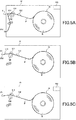
- FIG. 5A indicates an optional arrangement of the printer 10 having a separation issuance function.
- the separation issuance function the label PL on which print information is printed is separated from the mount PM and ejected to the outside of the printer 10.
- a separation unit 154 is disposed in the printer 10, in addition to the components shown in FIG. 4 .
- the separation unit 154 is configured to separate the label PL from the mount PM by diverging a feed path of the label PL on which print information is printed by the thermal head 151, from a feed path of the mount PM.
- FIG. 5B indicates an optional arrangement of the printer 10 having a continuous issuance function.
- the label PL on which print information is printed is ejected to the outside of the printer 10, with a number of labels PL temporarily attached to the mount PM.
- a cutter unit 155 is disposed in the printer 10, in addition to the components shown in FIG. 4 .
- the cutter unit 155 is configured to cut the mount PM in accordance with a drive signal generated by the driver circuit 15, at a position of the mount PM between a number of labels PL on which print information are printed by the thermal head 151 and a label PL on which print information is not printed.
- FIG. 5C indicates an optional arrangement of the printer 10 having a wireless communication function.
- wireless communication is performed with the server 30, for example, via the network NW.
- a wireless communication unit 153 is disposed in the printer 10, in addition to the components shown in FIG. 4 .
- the wireless communication unit 153 is connected to the communication interface 14.
- the wireless communication unit 153 establishes communication between the printer 10 and the server 30 in accordance with a control of the processor 12.
- the server 30 may include: a memory device 31, a processor 32, an input/output interface 33, and a communication interface 34, for example.
- the memory device 31 is configured to memorize program(s) and data.
- the memory device 31 may be a combination of a ROM, a RAM, and a storage such as a flash memory or a hard disk.
- the program(s) in the memory device 31 may include:
- the data in the memory device 31 may include:
- the processor 32 is configured to initiate the program(s) in the memory device 31 to realize the functions of the server 30.
- the processor 32 is an example of a computer.
- the input/output interface 33 is configured to obtain an user instruction from an input device connected to the server 30 and to output information to an output device connected to the server 30.
- input device may be a keyboard, a pointing device, a touch panel, or combination thereof, for example.
- the output device may be a display device, for example.
- the communication interface 34 is configured to control communication between the server 30 and the printer 10.
- FIG. 6 illustrates a data structure of the user information database of the present embodiment.
- the user information database of FIG. 6 includes user information regarding users.
- the user information database contains: a "User ID” field; a "User name” field; a “Contact” field; a "User property” field; and a "Supply serial” field.
- the "User ID” field holds a user ID (an example of "user identification information") for identifying a user.
- the user ID is arbitrarily determined by the server 30 when the user ID is registered in the server 30.
- the "User name” field holds information regarding a user name (a text, for example).
- the user name is arbitrarily determined by the server 30 when the user information is registered in the server 30.
- the "Contact” field holds information regarding user contact information such as a mail address, an account for login to the server 30, or a combination thereof.
- the "User property” field holds user property information regarding user property.
- the "User property” field includes a "Business category” field and a "Use location” field.
- the user property information is arbitrarily determined by the server 30 when the user information is registered in the server 30.
- the "Business category” field holds information regarding the user's business category.
- the "Use location” field holds information regarding a use location of the printer 10.
- the "Supply serial” field holds supply serial information for identifying a print medium P that the user possesses.
- the information held by the "Supply serial” field is updated when the user purchases a print medium P or the user has used up a print medium P.
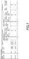
- FIG. 7 illustrates a data structure of a printer master database of the present embodiment.
- the printer master database of FIG. 7 includes communication parameters for each combination of a printer model ID and a supply ID.
- the printer master database is recorded in the memory device 31.
- the printer master database contains: a "Printer model ID” field; a "Model name” field; a “Printer serial” field; a “Supply ID” field; a "Communication parameters” field; and a "Print parameters” field.
- the "Printer model ID” field holds a printer model ID (an example of "printer identification information”) for identifying a printer.
- the "Model name” field holds information regarding a printer model name (a text, for example).
- the "Printer serial” field holds a printer serial code (an example of printer identification information), which is unique for each printer 10.
- a unique printer serial code is assigned to each of a plurality of printers 10 identified with a printer model ID.
- a printer serial code assigned to each printer 10 is recorded in the memory device 11.
- the "Supply ID” field holds a supply ID (an example of "print medium identification information”) for identifying a model number of a print medium P.
- the "Communication parameters" field holds communication parameters for the printer 10 to perform RFID communication.
- the communication parameters are optimized values which have been set, for each combination of a printer model and a type of a print medium P, in quality inspection included in a manufacturing process of the RFID tag RT.
- the "Communication parameters” field includes a "Write parameters” field and a "Read parameters” field.
- the "Write parameters” field holds write parameters which are referred to in RFID communication for writing information on the IC chip of the RFID tag RT (which is hereinafter called “write communication”).
- the "Read parameters” field holds read parameters which are referred to in RFID communication for reading information from the IC chip of the RFID tag RT (which is hereinafter called “read communication”).
- Each of the "Write parameters" field and the “Read parameters” field contains: a "Feed distance” field; a “Feed speed for communication” field; and an "Electromagnetic wave level” field.
- Each "Feed distance” field holds information regarding a feed distance required to reach a communication area (namely, a communication position) where the RFID tag RT can communicate with the reader/writer 152, in write communication or read communication. Such information may be a value in millimeter of a feed distance, for example.
- Each "Feed speed for communication" field holds information regarding a speed of the print medium P when the RFID tag RT passes the communication area (that is, a feed speed for communication), in write communication or read communication. Such information may be a value in inch per second of a feed speed for communication, for example.
- Each "Electromagnetic wave level" field holds information regarding intensity of electromagnetic wave emitted by the reader/writer 152 in write communication or read communication. Such information may be a value in dB of an electromagnetic wave level, for example.
- the "Print parameters” field holds printer parameters referred to in printing print information on the label PL.
- the "Print parameters” field includes a "Print density” field and a “Feed speed for printing” field.
- the "Print density” field holds information regarding a print density of print information. Such information may be a value of a temperature of the thermal head 151 or a voltage applied to the thermal head 151, for example.
- the "Feed speed for printing" field holds information regarding a feed speed of the print medium P when the print medium P is printed.
- Control for the RFID communication may be optimized based on a combination of a printer model and a type of the print medium P. Further, the RFID communication may be influenced by a configuration of the printer 10 such as a metal material used in the printer or a configuration of the print medium P such as label property of a paper substrate. Since the memory device 31 records communication parameters for each combination of a printer model ID and a supply ID, communication parameters can be provided to the printer 10 in accordance with a printer model of the printer 10 and a type of a print medium P stored in the printer 10.
- FIG. 8 illustrates a data structure of a supplies master database of the present embodiment.
- the supply master database of FIG. 8 includes supply information regarding a print medium P containing a RFID tag RT.
- the supply master database is recorded in the memory device 31.
- the supply master database contains: a "Supply ID” field; a "Supply name” field; a “Supply serial” field; a “Tag ID” field; and a "Supply property” field.
- the "Supply ID" field holds a supply ID for identifying a model number of a print medium P.
- the "Supply name” field holds information regarding a model name of the print medium P (a text, for example).
- the "Supply serial” field holds supply serial information (an example of "print medium identification information”), which is unique for each print medium P containing a RFID tag RT.
- supply serial information an example of "print medium identification information”
- One or a plurality of supply serial information is associated with a single supply ID.
- the "Tag ID” field holds a tag ID (an example of "tag identification information”) for identifying a RFID tag RT.
- the "Supply property” field holds supply property information (an example of "print medium property information") regarding a property of the print medium P.
- the "Supply property” contains: a "Label property” field; a “Label size” field; a “Chip maker” field; a “Chip type” field; an "Inlay maker” field; an “Inlay type” field; and an "Application” field.
- the "Label property" field holds label property information regarding a property of a label PL.
- An example of the label property information may be: information regarding manufacturing date of the label PL; information regarding manufacturing plant of the label PL; information regarding material of the label PL such as material of a paper substrate and adhesive; information regarding a printer 10 suitable for use of the label PL; and information regarding resolution suitable for printing on the label PL.
- the "Label size” field holds information regarding a label size of the label PL in the print medium P such as a longitudinal length P and a lateral length W.
- the "Chip maker” field holds information regarding a manufacturer of the IC chip of the RFID tag RT.
- the "Chip type” field holds information regarding a type of the IC chip.
- the "Inlay maker” field holds information regarding a manufacturer of an inlay of the RFID tag RT.
- the "Inlay type” field holds information regarding a type of the inlay.
- the "Application” field holds information regarding an application of the RFID tag RT such as "price label” or "ticket page.”
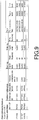
- FIG. 9 illustrates a data structure of a printer information database of the present embodiment.
- the printer information database of FIG. 9 contains printer information regarding a printer 10 registered by a user.
- the printer information database contains: a "Printer serial” field; a "Printer model ID” field; an “Optional arrangement” field; a "Read log” field; a “Write log” field; and an "Error” field.
- the printer information database is associated with a user ID.
- the "Printer serial" field holds a printer serial code unique for each printer 10.
- An unique printer serial code is assigned to each of the plurality of printer 10 identified by a printer model ID.
- the "Printer model ID" field holds a printer model ID of the printer 10 to which a printer serial code is assigned.
- the "Optional arrangement” field holds optional arrangement information regarding an optional arrangement of the printer 10.
- the "Optional arrangement” field includes a "Cutter unit ID” field, a “Separation unit ID” field, and a "Wireless communication unit ID” field.
- the "Cutter unit ID” field holds a cutter unit ID for identifying a cutter unit 155 attached to the printer 10.
- the "Separation unit ID" field holds a separation unit ID for identifying a separation unit 154 attached to the printer 10.
- the "Wireless communication unit ID" field holds a wireless communication unit ID for identifying a wireless communication unit 153 attached to the printer 10.
- the "Read log” field holds log information for read communication.
- the "Read log” field includes a "Supply serial” field and a "Read frequency” field.
- the "Supply serial” field holds supply serial information of the print medium P containing a RFID tag RT targeted for read communication.
- the "Read frequency” field holds information regarding a frequency of performing read communication.
- the "Write log” field holds log information for write communication.
- the "Write log” field includes a “Supply serial” field and a “Write frequency” field.
- the "Supply serial" field holds supply serial information of the print medium P containing a RFID tag RT targeted for write communication.
- the "Write frequency” field holds information regarding a frequency of performing write communication.
- the "Error” field holds error information regarding errors in RFID communication.
- the "Error” field includes a “Supply serial” field and an “Error code” field.
- the "Error occurrence date" field holds information regarding an error occurrence date.
- the "Supply serial" field holds supply serial information of the print medium P containing a RFID tag RT that have been used in RFID communication when an error occurred.
- the "Error code” field holds error code(s) indicating error type(s).
- FIG. 10 is a functional block diagram of the server and the printer of FIG. 1 .
- the processor 32 of the server 30 functions as a record unit 320, a first obtaining unit 321, an identifying unit 322, and a first transmission unit 323.
- the processor 12 of the printer 10 functions as a second transmission unit 120, a second obtaining unit 121, and a communication controller 122.
- the record unit 320 of the server 30 is configured to associate printer identification information (a printer model ID, for example) for identifying a printer 10 and print medium identification information (a supply ID, for example) for identifying a print medium P having a plurality of RFID tags RT, with communication parameters with which the printer 10 performs RFID communication, and record them in the memory device 31 in an associated manner.
- printer identification information a printer model ID, for example
- print medium identification information a supply ID, for example
- the record unit 320 of the server 30 is configured to associate tag identification information (a tag ID, for example) for identifying a RFID tag RT, with print medium identification information, and record them in the memory device 31 in an associated manner.
- tag identification information a tag ID, for example
- the second obtaining unit 121 of the printer 10 is configured to obtain printer identification information assigned to the printer 10, and tag identification information of the RFID tag RT contained in the print medium stored in the storage 16.
- the second transmission unit 120 of the printer 10 is configured to transmit the printer identification information and the tag identification information, which have been obtained by the second obtaining unit 121, to the server 30.
- the first obtaining unit 321 of the server 30 is configured to obtain the printer identification information and the tag identification information, which have been transmitted by the second transmission unit 120 of the printer 10.
- the identifying unit 322 of the server 30 is configured to access the memory device 31 to identify print medium identification information associated with the tag identification information that have been obtained by the first obtaining unit 321.
- the identifying unit 322 of the server 30 is configured to identify communication parameters associated with the print medium identification information, which have been identified, and the printer identification information that have been obtained by the first obtaining unit 321.
- the first transmission unit 323 of the server 30 is configured to transmit the communication parameters that have been identified by the identifying unit 322, to the printer 10.
- the second obtaining unit 121 of the printer 10 is configured to obtain the communication parameters that have been transmitted by the first transmission unit 323 of the server 30.
- the communication controller 122 of the printer 10 is configured to control the reader/writer 152 with reference to the communication parameters that have been obtained by the second obtaining unit 121, and to perform RFID communication in accordance with the communication parameters.
- the server 30 transmits communication parameters in accordance with a combination of a printer 10 and a RFID tag RT, to the printer 10.
- the printer 10 refers to the communication parameters that have been transmitted by the server 30, without performing calibration, and performs RFID communication. This allows proper communication parameters to be easily configured for RFID communication.
- FIG. 11 is a sequence chart of RFID communication processing of the present embodiment.
- FIG. 12 illustrates an example of a screen displayed during the processing of FIG. 11 .
- RFID communication processing of FIG. 11 is similarly performed irrespective of a type of RFID communication (namely, read communication or write communication).
- the printer 10 performs feeding (S100). Specifically, a user opens a printer cover and sets a paper roll R in the storage 16. Then, the user closes the printer cover and gives the printer 10 a user instruction for performing RFID communication.
- the driver circuit 15 generates a drive signal for the platen roller 150 to rotate the platen roller 150. Thereby, a belt-shaped print medium P is extracted from the paper roll R in the storage 16.
- the printer 10 obtains a tag ID (S101). Specifically, the reader/writer 152 reads a tag ID recorded in the top RFID tag RT among a plurality of RFID tags RT that is fed by the platen roller 150, in accordance with control of the communication controller 122.
- the printer 10 After the step S101, the printer 10 performs a parameter request (S102). Specifically, the second obtaining unit 121 of the printer 10 obtains: the tag ID read by the reader/writer 152 at the step S101; and a printer serial code recorded in the memory device 11.
- the second transmission unit 120 of the printer 10 transmits parameter request data to the server 30.
- the parameter request data includes the following information:
- the server 30 After the step S102, the server 30 performs identifying tag information (S300). Specifically, the identifying unit 322 of the server 30 accesses the supply master database (see FIG. 8 ) to identify: information regarding a supply name in the "Supply name” field associated with the tag ID in the parameter request data; supply serial information in the "Supply serial” field; and supply property information in the "Supply property” field.
- the supply master database see FIG. 8
- the server 30 matches the tag ID obtained from the printer 10 at the step S300, to the tag IDs recorded in the supply master database (see FIG. 8 ), and determines true or false regarding the RFID tag (S301).
- the processor 32 determines that the RFID tag used in the communication is false (NO in S301). In this case, the server 30 transmits false notification data to the printer 10.
- the false notification data includes a message indicating that the RFID tag is false.
- the processor 32 determines that the RFID tag used in the communication is true (YES in S301), and proceeds to identifying communication parameters (S302).
- the processor 32 which performs the step S301, functions as a determination unit for determining true or false of the RFID tag by matching the tag ID that have been obtained by the first obtaining unit 321, to the tag IDs recorded in the memory device 31.
- the printer 10 performs displaying (S103).
- the processor 12 is configured to display a screen P100 (see FIG. 12A ) on the display device, in response to the false notification data that have been transmitted from the server 30 at the step S301.
- the screen P100 includes a message indicating that the RFID tag RT is false.
- the server 30 performs identifying communication parameters (S302). For example, the identifying unit 322 of the server 30 identifies a corresponding supply ID, by matching the tag ID that have been obtained by the first obtaining unit 321, to the tag IDs recorded in the memory device 31. More specifically, the identifying unit 322 accesses the supply master database (see FIG. 8 ) to identify a supply ID in the "Supply ID" field associated with the tag ID in the parameter request data (which is hereinafter called "target supply ID").
- the identifying unit 322 of the server 30 accesses the printer master database (see FIG. 7 ) to identify a record associated with the printer serial code in the parameter request data (which is hereinafter called "target printer model record").
- the identifying unit 322 refers to the target printer model record to identify a "Communication parameters" field associated with the target supply ID.
- the identifying unit 322 identifies communication parameters (read parameters or write parameters) in a field corresponding to a type of communication from the "Read parameter” field and the "Writer parameter” field of the "Communication parameter” field which have been identified.
- the identifying unit 322 of the server 30 identifies communication parameters by matching: the target supply ID; and the printer serial code that have been obtained by the first obtaining unit 321, to the supply IDs and the printer serial codes recorded in the memory device 31.
- the server 30 After the step S302, the server 30 performs a parameter response (S303). Specifically, the identifying unit 322 of the server 30 accesses the user information database (see FIG. 6 ) to identify a user name associated with the tag ID contained in the parameter request data.
- the first transmission unit 323 of the server 30 transmits the parameter response data to the printer 10.
- the parameter response data contains:
- the printer 10 displays a screen (S104). Specifically, the second obtaining unit 121 of the printer 10 obtains the parameter response data transmitted from the server 30 at the step S303.
- the processor 12 is configured to display a screen P102 (see FIG. 12B ) on the display device based on the parameter response data.
- the screen P102 includes a display object A102 and button objects B102a to B102b.
- the display object A102 contains: information regarding a user name in the parameter response data; a supply name; supply property information (a label size, a chip type, and information regarding an application, for example); and communication parameters (a feed distance, a feed speed for communication, and an electromagnetic wave level, for example).
- the button object B102a receives a user instruction to initiate communication.
- the button object B102b receives a user instruction to terminate communication.
- the printer 10 After the step S104, the printer 10 performs RFID communication (S105). Specifically, when a user operates the button object B102a (see FIG. 12 ), the processor 12 receives a user instruction to initiate RFID communication.
- the processor 12 initiates a RFID communication sequence in response to the user instruction. Specifically, the communication controller 122 of the printer 10 records the communication parameters, which is contained in the parameter response data, in the memory device 11.
- the driver circuit 15 generates a drive signal for the platen roller 150 to rotate the platen roller 150, which allows a belt-shaped print medium P to be extracted from a paper roll R in the storage 16.
- the communication controller 122 of the printer 10 generates a communication control signal for controlling the reader/writer 152 based on the communication parameters recorded in the memory device 11.
- the communication control signal has a signal wave corresponding to a feed distance, a feed speed for communication, and an electromagnetic wave level, which are contained in the communication parameters.
- the reader/writer 152 performs RFID communication in accordance with the communication control signal that have been generated by the communication controller 122 of the printer 10.
- the printer 10 After the step S105, the printer 10 performs a log update request (S106). Specifically, the processor 12 transmits log update request data to the server 30.
- the log update request data contains:
- the server 30 After the step S106, the server 30 performs update for the database (S304). Specifically, the record unit 320 of the server 30 updates values in a field ("Read log” field or "Write log” field) that corresponds to a type of RFID communication, in the printer information database (see FIG. 9 ) associated with a printer serial code in the log update request data, such that:
- the server 30 transmits communication parameters to the printer 10 (S303).
- the transmitted communication parameters correspond to a combination of the printer 10 and the RFID tag RT.
- the printer 10 does not perform calibration, but records the communication parameters, which have been transmitted from the server 30, in the memory device 11 (S105).
- the server 30 transmits supply property information to the printer 10.
- the transmitted supply property information is associated with a tag ID that have been obtained from the printer 10.
- the printer 10 displays the supply property information that have been transmitted from the server 30. Thereby, property of print medium P containing a RFID tag used by a user can be presented to the user.
- the server 30 matches the tag ID that have been obtained from the printer 10, to tag IDs recorded in the supply master database (see FIG. 8 ), thereby enabling judgment as to whether the RFID tag RT used by the user is true or not.
- FIG. 13 is a sequence chart of error registration processing of the present embodiment.
- FIG. 14 illustrates an example of a screen displayed during the processing of FIG. 13 .
- step S105 of FIG. 11 the printer 10 performs displaying an error screen (S110). Specifically, the processor 12 displays a screen P110 ( FIG. 14 ) on the display device.
- the screen P110 includes a display object A110 and button objects B110a to B110b.
- the display object A110 includes the error code occurred in the step S105, the tag ID of the RFID tag RT targeted in the RFID communication (S105), and an error occurrence date.
- the button object B102a is an object for receiving a user instruction to initiate error registration processing.
- the button object B102b is an object for receiving a user instruction to terminate error registration processing.
- the printer 10 After the step S110, the printer 10 performs a log update request (Sill). Specifically, when a user operates the button object B110a, the processor 12 transmits log update request data to the server 30.
- the log update request data contains:
- the server 30 After the step Sill, the server 30 performs database update (S310). Specifically, the identifying unit 322 of the server 30 accesses the supply master database ( FIG. 8 ) to identify supply serial information of the "Supply serial" field associated with the tag ID in the log update request data.
- the record unit 320 of the server 30 accesses the printer information database ( FIG. 9 ) associated with the printer serial code in the log update request data, and updates the printer information database such that:
- the modified example 1 represents an example of the server 30 that transmits communication parameters to the printer 10.
- the communication parameters corresponds to a combination of the printer 10, the RFID tag RT, and user property.
- FIG. 15 illustrates a data structure of a printer master database of the modified example 1.
- the database of FIG. 15 is different from that of FIG. 7 in terms that the database of FIG. 15 has a "User property" field.
- the "User property” field holds user property information regarding property of a user.
- the "User property” field includes a "Business category” field and a "Use location” field.
- the "Business category” field holds information regarding a business category of a user.
- the “Use location” field holds information regarding a use location of the printer 10.
- RFID communication is influenced by a use condition by a user.
- the user condition may include an application of the RFID tag RT or environment in which the printer 10 is used, such as a temperature of a location where the printer 10 is used.
- communication parameters are recorded in the memory device 31 for each combination of a printer model ID, a supply ID, and user property information.
- communication parameters can be provided to the printer 10 in accordance with a combination of a printer model, a type of the print medium P, and user property, thereby reducing influence of a use condition by a user.
- User property information regarding property of a user of the printer 10 is recorded in the memory device 11 of the modified example 1.
- the user property information is set by a user as appropriate.
- the second obtaining unit 121 of the printer 10 obtains the user property information recorded in the memory device 11.
- the second transmission unit 120 of the printer 10 transmits parameter request data to the server 30.
- the parameter request data contains:
- the identifying unit 322 of the server 30 accesses the printer master database ( FIG. 15 ) to identify a target printer record and to then identify user property information in the "User property" field of the target printer record.
- the identifying unit 322 of the server 30 identifies communication parameters associated with the user property information.
- RFID communication is performed by use of communication parameters optimized for property of a user.
- communication parameter setting adapted to user circumstance such as use location can be easily performed.
- the modified example 2 represents an example of the server 30 that transmits communication parameters to the printer 10.
- the communication parameters corresponds to a combination of the printer 10, the RFID tag RT, and printer configuration.
- FIG. 16 illustrates a data structure of a printer master database of a modified example 2.
- the database of FIG. 16 is different from that of FIG. 7 in terms that the database of FIG. 15 has a "Optional configuration" field.
- the "Optional configuration” field holds optional configuration information regarding optional configuration of the printer 10.
- the "Optional configuration” field includes a "Cutter unit ID” field, a “Separation unit ID” field, and a "Wireless communication unit ID” field.
- the "Cutter unit ID” field holds a cutter unit ID for identifying a cutter unit 155 attached to the printer 10.
- the "Separation unit ID” field holds a separation unit ID for identifying a separation unit 154 attached to the printer 10.
- the "Wireless communication unit ID” field holds a wireless communication unit ID for identifying a wireless communication unit 153 attached to the printer 10.
- Each subfield (namely, each of the "Feed distance” field, the “Feed speed for communication” field, and the “Electromagnetic wave level” field) of the "Communication parameters” field is associated with each subfield (namely, each of the "Cutter unit ID” field, the “Separation unit ID” field, and the “Wireless communication unit ID” field) of the "Optional configuration” field.
- Each subfield of the "Communication parameters" field holds optimized communication parameters for configuration of the printer 10.
- RFID communication is influenced by an optional configuration (the separation unit 154, for example) of the printer 10.
- the separation unit 154 for example, it is influenced by a conductive member of metal portions or the like of the separation unit 154.
- communication parameters are recorded in the memory device 31 for each combination of a printer model ID, a supply ID, and optional configuration information.
- communication parameters can be provided to the printer 10 in accordance with a combination of a printer model, a type of the print medium P, and optional configuration, thereby reducing influence of optional configuration.
- FIG. 17 is a sequence chart of option set processing of the modified example 2.
- FIG. 18 illustrates an example of a screen displayed during the processing of FIG. 17 .
- the printer 10 performs reception of optional configuration (S120). Specifically, the processor 12 displays a screen P120 ( FIG. 18 ) on the display device.
- the screen P120 includes a button object B120 and an input filed object F120.
- the input filed object F120 is an object for receiving optional configuration information regarding optional configuration such as: a cutter unit ID of the cutter unit 155, a separation unit ID of the separation unit 154, and a wireless communication unit ID of the wireless communication unit 153.
- the button object B120 is an object for receiving a user instruction to initiate an option parameters request (S121).
- the printer 10 After the S120, the printer 10 performs an option parameters request (S121). Specifically, when a user inputs optional configuration information into the input filed object F120 of FIG. 18 and operates the button object B120, the processor 12 transmits option parameters request data to the server 30.
- the option parameters request data contains:
- the server 30 After the step S121, the server 30 performs database update (S320). Specifically, the record unit 320 of the server 30 accesses the printer information database ( FIG. 9 ) associated with a printer serial code in the option parameters request data, and records optional configuration information (namely, a cutter unit ID of the cutter unit 155, a separation unit ID of the separation unit 154, and a wireless communication unit ID of the wireless communication unit 153 ) contained in the option parameters request data, in each subfield of the "Optional configuration" field.
- the printer information database FIG. 9
- optional configuration information namely, a cutter unit ID of the cutter unit 155, a separation unit ID of the separation unit 154, and a wireless communication unit ID of the wireless communication unit 153
- the server 30 identifies information contained in the "Optional configuration" field associated with a printer serial code in the parameters request data (that is, optional configuration data regarding optional parts attached to the printer 10 ).
- the server 30 identifies a target printer record in the printer master database ( FIG. 16 ), and then identifies communication parameters associated with the optional configuration data, in the target printer records that have been identified.
- RFID communication is performed by use of communication parameters optimized for configuration of the printer 10, thereby reducing probability of error occurrence in the RFID communication.
- the modified example 3 represents an example to facilitate an order for a print medium P containing a RFID tag RT in accordance with use frequency of the RFID tag RT.
- the server 30 of the modified example 3 is configured to calculate communication frequency for each supply ID based on information contained in the "Read frequency” field and the "Write frequency” field of the printer information database ( FIG. 9 ).
- the server 30 is configured to calculate a remaining amount of a RFID tag RT identified by each supply ID. If the calculated remaining amount is equal to or less than a predetermined value, the server 30 transmits purchase facilitation information to a predetermined contact (for example, a contact identified by information that a "Contact" field holds).
- the purchase facilitation information is for facilitating an order for the print medium P.
- the server 30 manages a remaining amount of each RFID tag RT, and transmits purchase facilitation information to a predetermined contact when that amount becomes small. Thereby, a user is encouraged to purchase a RFID tag RT at a proper time.
- the modified example 4 represents an example of the server 30 that identifies communication parameters to be transmitted to a printer 10, based on a combination of user identification information and tag identification information.
- a user ID of a user using the printer 10 is stored in the memory device 11 according to the modified example 4.
- Single printer serial information is stored in the printer information database ( FIG. 9 ). That is, a single user uses only one printer 10. In other words, a number of records of the printer information database is one.
- the second obtaining unit 121 of the printer 10 obtains a user ID recorded in the memory device 11.
- the second transmission unit 120 of the printer 10 transmits parameters request data to the server 30.
- the parameters request data contains:
- the identifying unit 322 of the server 30 accesses the printer information database ( FIG. 9 ) associated with the user ID in the parameters request data to identify a printer serial code of the printer 10.
- the identifying unit 322 of the server 30 accesses the printer master database ( FIG. 7 ) to identify a target printer record associated with the printer serial code that have been identified.
- Processes thereafter may be the same as those in the present embodiment ( FIG. 11 ).
- the printer 10 transmits user identification information in exchange of printer identification information to the server 30, the modified example 4 exerts the same advantageous effect as the present embodiment.
- the modified example 5 represents an example of the server 30 that transmits communication parameters associated with a printer serial code and a tag ID, to the printer 10.
- FIG. 19 illustrates a data structure of a printer master database of a modified example 5.
- the database of FIG. 19 is different from that of FIG. 7 in terms that the database of FIG. 19 contains a "Tag ID” field in exchange of the "Supply ID” field ( FIG. 7 ).
- the "Tag ID” field holds a tag ID.
- the identifying unit 322 of the server 30 accesses the printer master database ( FIG. 7 ) to identify a "Communication parameters" field associated with a printer serial code and a tag ID in the parameters request data.
- the step 302 may be performed every time RFID communication is performed with a RFID tag.
- Processes thereafter may be the same as those in the present embodiment ( FIG. 11 ).
- the modified example 5 easily enables proper communication parameters setting for RFID communication.
- the memory device 11 may be connected to the printer 10 through the network NW.
- the memory device 31 may be connected to the server 30 through the network NW.
- communication parameters and print parameters are associated with a supply ID in the printer master database ( FIG. 7 ).
- communication parameters and print parameters may be associated with a tag ID.
- the present invention may include a computer-readable recording media (including non-volatile type) in which a program is recorded.
Landscapes
- Engineering & Computer Science (AREA)
- Theoretical Computer Science (AREA)
- Human Computer Interaction (AREA)
- Physics & Mathematics (AREA)
- General Engineering & Computer Science (AREA)
- General Physics & Mathematics (AREA)
- Accessory Devices And Overall Control Thereof (AREA)
Abstract
Description
- The present invention relates to a server, a printer, and a program.
- In recent years, printers are prevalent which has a printing function for printing print information on a print medium and a communicating function for performing communication with a Radio Frequency Identification (RFID) tag contained in the print medium (which is hereinafter called "RFID communication"). See the specification of the United States Patent No.
7,190,270 , for example. - With these printers, calibration is generally performed for setting communication parameters used in RFID communication to, before the RFID communication is performed, and then a user operates to set communication parameters based on a calibration result.
- However, setting parameters by a user requires experiences and much work. Further, setting parameters manually may cause a mistake such as erroneous setting. Thus, proper communication parameters setting for RFID communication has not been easy.
- In view of the above, the present invention aims to enable proper communication parameters setting for RFID communication in an easy manner.
- An embodiment of the present invention is a server capable of communicating with a printer or printers, each performing radio frequency identification (RFID) communication with a RFID tag, the server comprising: a record unit configured to record, in a memory device, printer identification information for identifying a printer, tag identification information for identifying a RFID tag, and communication parameters with which the printer performs RFID communication, in an associated manner; a first obtaining unit configured to obtain, from a printer, printer identification information and tag identification information read by the printer; an identifying unit configured to identify communication parameters associated with the printer identification information and the tag identification information obtained by the first obtaining unit; and a first transmission unit configured to transmit the communication parameters identified by the identifying unit, to the printer.
- According to an embodiment of the present invention, it is enabled proper communication parameters setting for RFID communication in an easy manner.
-
-
FIG. 1 is a schematic view of an information processing system according to the present embodiment. -
FIG. 2 is a schematic view of the print medium inFIG. 1 . -
FIG. 3 is a block diagram showing a configuration of the information processing system ofFIG. 1 . -
FIG. 4 is a schematic view showing an internal arrangement of the printer ofFIG. 3 . -
FIG. 5 is a schematic view showing optional arrangements of the printer ofFIG. 4 . -
FIG. 6 illustrates a data structure of a user information database of the present embodiment. -
FIG. 7 illustrates a data structure of a printer master database of the present embodiment. -
FIG. 8 illustrates a data structure of a supply master database of the present embodiment. -
FIG. 9 illustrates a data structure of a printer information database of the present embodiment. -
FIG. 10 is a functional block diagram of the server ofFIG. 1 . -
FIG. 11 is a sequence chart of RFID communication processing of the present embodiment. -
FIG. 12 illustrates an example of a screen displayed during the processing ofFIG. 11 . -
FIG. 13 is a sequence chart of error registration processing of the present embodiment. -
FIG. 14 illustrates an example of a screen displayed during the processing ofFIG. 13 . -
FIG. 15 illustrates a data structure of a printer master database of a modified example 1. -
FIG. 16 illustrates a data structure of a printer master database of a modified example 2. -
FIG. 17 is a sequence chart of option set processing of the modified example 2. -
FIG. 18 illustrates an example of a screen displayed during the processing ofFIG. 17 . -
FIG. 19 illustrates a data structure of a printer master database of a modified example 5. - The present invention relates to a Japanese patent application
2017-251193 - An embodiment of the present invention will be described in detail hereinafter with reference to the attached drawings. In the drawings for explaining the present embodiment, an identical sign will be generally denoted regarding the corresponding element, and thus repeated explanation will be omitted for the corresponding element.
- A configuration of an information processing system will be described.
FIG. 1 is a schematic view of the information processing system according to the present embodiment.FIG. 2 is a schematic view of the print medium inFIG. 1 . - As illustrated in
FIG. 1 , theinformation processing system 1 includes a plurality of printers 10-1, 10-2 and aserver 30. In the following description, each of a printer 10-1 and a printer 10-2 may be denoted as "printer 10" unless the printers are particularly discerned. - The
printer 10 and theserver 30 are connected through a network NW such as Internet or an intranet. - As illustrated in
FIG. 2 , a print medium P contains a mount PM, a plurality of labels PL, and a plurality of RFID tags RT, each of which is embedded in each label PL. - An upper face of each label PL is a print face Sp on which printing can be performed by the
printer 10. Each label PL is temporarily attached to the mount PM, with a predetermined interval, along a feeding direction (namely, X-direction) of the print medium P. - The
printer 10 ofFIG. 1 has a printing function for printing print information on the label PL and a communicating function for performing RFID communication. The RFID communication according to the present embodiment includes communication for writing information on an Integrated Circuit (IC) chip of the RFID tag RT and communication for reading information from the RFID tag RT. Theprinter 10 is a thermal printer, for example. - The
server 30 is an example of an information processing apparatus that provides theprinter 10 with a response regarding a request transmitted from theprinter 10. For example, theserver 30 may be a web-server, and may be a program or a computer configured to perform HTTP communication with a software on the printer side. - A configuration of the
printer 10 will be described. It is to be noted that, for convenience, a configuration will be exemplified in which the only oneprinter 10 and theserver 30 are connected.FIG. 3 is a block diagram showing a configuration of the information processing system ofFIG. 1 .FIG. 4 is a schematic view showing an internal configuration of the printer ofFIG. 3 .FIG. 5 is a schematic view showing optional configurations of the printer ofFIG. 4 . - As illustrated in
FIG. 2 , theprinter 10 may include: amemory device 11, aprocessor 12, an input/output interface 13, acommunication interface 14, and adriver circuit 15, for example. - The
memory device 11 is configured to memorize program(s) and data. Thememory device 11 may be a combination of a read-only memory (ROM), a random access memory (RAM), and a storage such as a flash memory or a hard disk. - The program(s) in the
memory device 11 may include: - Operating system (OS);
- Firmware for controlling each component of the
printer 10; and - Application programs of the
printer 10. - The data in the
memory device 11 may include: - Databases accessed when information processing is executed;
- Data obtained through an execution result of information processing (namely, an execution result of information processing, per se);
- Parameters read by the firmware; and
- Printer information regarding the printer (a printer serial code assigned to the
printer 10, for example). - The
processor 12 is configured to initiate the program(s) in thememory device 11 to realize the functions of theprinter 10. Theprocessor 12 is an example of a computer. - The input/
output interface 13 is configured to obtain a user instruction from an input device connected to theprinter 10 and to output information to an output device connected to theprinter 10. The input device may be physical button(s), a touch panel, or combination thereof, for example. The output device may be a display device, for example. - The
communication interface 14 is configured to control communication between theprinter 10 and theserver 30. - The
driver circuit 15 is configured to generate a drive signal for driving each component of theprinter 10. - As illustrated in
FIG. 4 , aplaten roller 150, athermal head 151, a reader/writer 152, and astorage 16 are disposed in theprinter 10. - A paper roll R is stored in the
storage 16. The front end of the paper roll R is pinched by theplaten roller 150 and thethermal head 151. Theplaten roller 150 rotates in accordance with a drive signal generated by thedriver circuit 15 to feed the belt-shaped print medium P extracted from the paper roll R, which is stored in thestorage 16. - The
thermal head 151 is heated in accordance with a drive signal generated by thedriver circuit 15 to print print information on the label PL of the print medium P fed by theplaten roller 150. - The reader/
writer 152 is configured to perform RFID communication in accordance with a drive signal generated by thedriver circuit 15. -
FIG. 5A indicates an optional arrangement of theprinter 10 having a separation issuance function. With the separation issuance function, the label PL on which print information is printed is separated from the mount PM and ejected to the outside of theprinter 10. - As illustrated in
FIG. 5A , aseparation unit 154 is disposed in theprinter 10, in addition to the components shown inFIG. 4 . - The
separation unit 154 is configured to separate the label PL from the mount PM by diverging a feed path of the label PL on which print information is printed by thethermal head 151, from a feed path of the mount PM. -
FIG. 5B indicates an optional arrangement of theprinter 10 having a continuous issuance function. With the continuous issuance function, the label PL on which print information is printed is ejected to the outside of theprinter 10, with a number of labels PL temporarily attached to the mount PM. - As illustrated in
FIG. 5B , acutter unit 155 is disposed in theprinter 10, in addition to the components shown inFIG. 4 . - The
cutter unit 155 is configured to cut the mount PM in accordance with a drive signal generated by thedriver circuit 15, at a position of the mount PM between a number of labels PL on which print information are printed by thethermal head 151 and a label PL on which print information is not printed. -
FIG. 5C indicates an optional arrangement of theprinter 10 having a wireless communication function. With the wireless communication function, wireless communication is performed with theserver 30, for example, via the network NW. - As illustrated in
FIG. 5C , awireless communication unit 153 is disposed in theprinter 10, in addition to the components shown inFIG. 4 . - The
wireless communication unit 153 is connected to thecommunication interface 14. Thewireless communication unit 153 establishes communication between theprinter 10 and theserver 30 in accordance with a control of theprocessor 12. - A configuration of the
server 30 will be described. - As illustrated in
FIG. 3 , theserver 30 may include: amemory device 31, aprocessor 32, an input/output interface 33, and acommunication interface 34, for example. - The
memory device 31 is configured to memorize program(s) and data. Thememory device 31 may be a combination of a ROM, a RAM, and a storage such as a flash memory or a hard disk. - The program(s) in the
memory device 31 may include: - Operating system (OS); and
- Application programs for executing information processing.
- The data in the
memory device 31 may include: - Database accessed when information processing is executed; and
- Execution result of information processing.
- The
processor 32 is configured to initiate the program(s) in thememory device 31 to realize the functions of theserver 30. Theprocessor 32 is an example of a computer. - The input/
output interface 33 is configured to obtain an user instruction from an input device connected to theserver 30 and to output information to an output device connected to theserver 30. Then input device may be a keyboard, a pointing device, a touch panel, or combination thereof, for example. The output device may be a display device, for example. - The
communication interface 34 is configured to control communication between theserver 30 and theprinter 10. - Databases of the present embodiment will be described. The databases described below is memorized in the
memory device 31. - A user information database of the present embodiment will be described.
FIG. 6 illustrates a data structure of the user information database of the present embodiment. - The user information database of
FIG. 6 includes user information regarding users. The user information database contains: a "User ID" field; a "User name" field; a "Contact" field; a "User property" field; and a "Supply serial" field. - The "User ID" field holds a user ID (an example of "user identification information") for identifying a user. The user ID is arbitrarily determined by the
server 30 when the user ID is registered in theserver 30. - The "User name" field holds information regarding a user name (a text, for example). The user name is arbitrarily determined by the
server 30 when the user information is registered in theserver 30. - The "Contact" field holds information regarding user contact information such as a mail address, an account for login to the
server 30, or a combination thereof. - The "User property" field holds user property information regarding user property. The "User property" field includes a "Business category" field and a "Use location" field. The user property information is arbitrarily determined by the
server 30 when the user information is registered in theserver 30. The "Business category" field holds information regarding the user's business category. The "Use location" field holds information regarding a use location of theprinter 10. - The "Supply serial" field holds supply serial information for identifying a print medium P that the user possesses. The information held by the "Supply serial" field is updated when the user purchases a print medium P or the user has used up a print medium P.
- A printer master database of the present embodiment will be described.
FIG. 7 illustrates a data structure of a printer master database of the present embodiment. - The printer master database of
FIG. 7 includes communication parameters for each combination of a printer model ID and a supply ID. The printer master database is recorded in thememory device 31. - The printer master database contains: a "Printer model ID" field; a "Model name" field; a "Printer serial" field; a "Supply ID" field; a "Communication parameters" field; and a "Print parameters" field.
- The "Printer model ID" field holds a printer model ID (an example of "printer identification information") for identifying a printer.
- The "Model name" field holds information regarding a printer model name (a text, for example).
- The "Printer serial" field holds a printer serial code (an example of printer identification information), which is unique for each
printer 10. A unique printer serial code is assigned to each of a plurality ofprinters 10 identified with a printer model ID. A printer serial code assigned to eachprinter 10 is recorded in thememory device 11. - The "Supply ID" field holds a supply ID (an example of "print medium identification information") for identifying a model number of a print medium P.
- The "Communication parameters" field holds communication parameters for the
printer 10 to perform RFID communication. The communication parameters are optimized values which have been set, for each combination of a printer model and a type of a print medium P, in quality inspection included in a manufacturing process of the RFID tag RT. - The "Communication parameters" field includes a "Write parameters" field and a "Read parameters" field. The "Write parameters" field holds write parameters which are referred to in RFID communication for writing information on the IC chip of the RFID tag RT (which is hereinafter called "write communication"). The "Read parameters" field holds read parameters which are referred to in RFID communication for reading information from the IC chip of the RFID tag RT (which is hereinafter called "read communication").
- Each of the "Write parameters" field and the "Read parameters" field contains: a "Feed distance" field; a "Feed speed for communication" field; and an "Electromagnetic wave level" field.
- Each "Feed distance" field holds information regarding a feed distance required to reach a communication area (namely, a communication position) where the RFID tag RT can communicate with the reader/
writer 152, in write communication or read communication. Such information may be a value in millimeter of a feed distance, for example. - Each "Feed speed for communication" field holds information regarding a speed of the print medium P when the RFID tag RT passes the communication area (that is, a feed speed for communication), in write communication or read communication. Such information may be a value in inch per second of a feed speed for communication, for example.
- Each "Electromagnetic wave level" field holds information regarding intensity of electromagnetic wave emitted by the reader/
writer 152 in write communication or read communication. Such information may be a value in dB of an electromagnetic wave level, for example. - The "Print parameters" field holds printer parameters referred to in printing print information on the label PL. The "Print parameters" field includes a "Print density" field and a "Feed speed for printing" field.
- The "Print density" field holds information regarding a print density of print information. Such information may be a value of a temperature of the
thermal head 151 or a voltage applied to thethermal head 151, for example. - The "Feed speed for printing" field holds information regarding a feed speed of the print medium P when the print medium P is printed.
- Control for the RFID communication may be optimized based on a combination of a printer model and a type of the print medium P. Further, the RFID communication may be influenced by a configuration of the
printer 10 such as a metal material used in the printer or a configuration of the print medium P such as label property of a paper substrate. Since thememory device 31 records communication parameters for each combination of a printer model ID and a supply ID, communication parameters can be provided to theprinter 10 in accordance with a printer model of theprinter 10 and a type of a print medium P stored in theprinter 10. - A supply master database of the present embodiment will be described.
FIG. 8 illustrates a data structure of a supplies master database of the present embodiment. - The supply master database of
FIG. 8 includes supply information regarding a print medium P containing a RFID tag RT. The supply master database is recorded in thememory device 31. - The supply master database contains: a "Supply ID" field; a "Supply name" field; a "Supply serial" field; a "Tag ID" field; and a "Supply property" field.
- The "Supply ID" field holds a supply ID for identifying a model number of a print medium P.
- The "Supply name" field holds information regarding a model name of the print medium P (a text, for example).
- The "Supply serial" field holds supply serial information (an example of "print medium identification information"), which is unique for each print medium P containing a RFID tag RT. One or a plurality of supply serial information is associated with a single supply ID.
- The "Tag ID" field holds a tag ID (an example of "tag identification information") for identifying a RFID tag RT.
- The "Supply property" field holds supply property information (an example of "print medium property information") regarding a property of the print medium P. The "Supply property" contains: a "Label property" field; a "Label size" field; a "Chip maker" field; a "Chip type" field; an "Inlay maker" field; an "Inlay type" field; and an "Application" field.
- The "Label property" field holds label property information regarding a property of a label PL. An example of the label property information may be: information regarding manufacturing date of the label PL; information regarding manufacturing plant of the label PL; information regarding material of the label PL such as material of a paper substrate and adhesive; information regarding a
printer 10 suitable for use of the label PL; and information regarding resolution suitable for printing on the label PL. - The "Label size" field holds information regarding a label size of the label PL in the print medium P such as a longitudinal length P and a lateral length W.
- The "Chip maker" field holds information regarding a manufacturer of the IC chip of the RFID tag RT.
- The "Chip type" field holds information regarding a type of the IC chip.
- The "Inlay maker" field holds information regarding a manufacturer of an inlay of the RFID tag RT.
- The "Inlay type" field holds information regarding a type of the inlay.
- The "Application" field holds information regarding an application of the RFID tag RT such as "price label" or "ticket page."
- A printer information database of the present embodiment will be described.
FIG. 9 illustrates a data structure of a printer information database of the present embodiment. - The printer information database of
FIG. 9 contains printer information regarding aprinter 10 registered by a user. - The printer information database contains: a "Printer serial" field; a "Printer model ID" field; an "Optional arrangement" field; a "Read log" field; a "Write log" field; and an "Error" field. The printer information database is associated with a user ID.
- The "Printer serial" field holds a printer serial code unique for each
printer 10. An unique printer serial code is assigned to each of the plurality ofprinter 10 identified by a printer model ID. - The "Printer model ID" field holds a printer model ID of the
printer 10 to which a printer serial code is assigned. - The "Optional arrangement" field holds optional arrangement information regarding an optional arrangement of the
printer 10. The "Optional arrangement" field includes a "Cutter unit ID" field, a "Separation unit ID" field, and a "Wireless communication unit ID" field. - The "Cutter unit ID" field holds a cutter unit ID for identifying a
cutter unit 155 attached to theprinter 10. - The "Separation unit ID" field holds a separation unit ID for identifying a
separation unit 154 attached to theprinter 10. - The "Wireless communication unit ID" field holds a wireless communication unit ID for identifying a
wireless communication unit 153 attached to theprinter 10. - The "Read log" field holds log information for read communication. The "Read log" field includes a "Supply serial" field and a "Read frequency" field.
- The "Supply serial" field holds supply serial information of the print medium P containing a RFID tag RT targeted for read communication.
- The "Read frequency" field holds information regarding a frequency of performing read communication.
- The "Write log" field holds log information for write communication. The "Write log" field includes a "Supply serial" field and a "Write frequency" field.
- The "Supply serial" field holds supply serial information of the print medium P containing a RFID tag RT targeted for write communication.
- The "Write frequency" field holds information regarding a frequency of performing write communication.
- The "Error" field holds error information regarding errors in RFID communication. The "Error" field includes a "Supply serial" field and an "Error code" field.
- The "Error occurrence date" field holds information regarding an error occurrence date.
- The "Supply serial" field holds supply serial information of the print medium P containing a RFID tag RT that have been used in RFID communication when an error occurred.
- The "Error code" field holds error code(s) indicating error type(s).
- A functional block according to the present embodiment will be described with reference to
FIG. 10. FIG. 10 is a functional block diagram of the server and the printer ofFIG. 1 . - As shown in
FIG. 10 , theprocessor 32 of theserver 30 functions as arecord unit 320, a first obtainingunit 321, an identifyingunit 322, and afirst transmission unit 323. Theprocessor 12 of theprinter 10 functions as asecond transmission unit 120, a second obtainingunit 121, and acommunication controller 122. - The
record unit 320 of theserver 30 is configured to associate printer identification information (a printer model ID, for example) for identifying aprinter 10 and print medium identification information (a supply ID, for example) for identifying a print medium P having a plurality of RFID tags RT, with communication parameters with which theprinter 10 performs RFID communication, and record them in thememory device 31 in an associated manner. - The
record unit 320 of theserver 30 is configured to associate tag identification information (a tag ID, for example) for identifying a RFID tag RT, with print medium identification information, and record them in thememory device 31 in an associated manner. - The second obtaining
unit 121 of theprinter 10 is configured to obtain printer identification information assigned to theprinter 10, and tag identification information of the RFID tag RT contained in the print medium stored in thestorage 16. - The
second transmission unit 120 of theprinter 10 is configured to transmit the printer identification information and the tag identification information, which have been obtained by the second obtainingunit 121, to theserver 30. - The first obtaining
unit 321 of theserver 30 is configured to obtain the printer identification information and the tag identification information, which have been transmitted by thesecond transmission unit 120 of theprinter 10. - The identifying
unit 322 of theserver 30 is configured to access thememory device 31 to identify print medium identification information associated with the tag identification information that have been obtained by the first obtainingunit 321. - Additionally, the identifying
unit 322 of theserver 30 is configured to identify communication parameters associated with the print medium identification information, which have been identified, and the printer identification information that have been obtained by the first obtainingunit 321. - The
first transmission unit 323 of theserver 30 is configured to transmit the communication parameters that have been identified by the identifyingunit 322, to theprinter 10. - The second obtaining
unit 121 of theprinter 10 is configured to obtain the communication parameters that have been transmitted by thefirst transmission unit 323 of theserver 30. - The
communication controller 122 of theprinter 10 is configured to control the reader/writer 152 with reference to the communication parameters that have been obtained by the second obtainingunit 121, and to perform RFID communication in accordance with the communication parameters. - As described above, the
server 30 transmits communication parameters in accordance with a combination of aprinter 10 and a RFID tag RT, to theprinter 10. Theprinter 10 refers to the communication parameters that have been transmitted by theserver 30, without performing calibration, and performs RFID communication. This allows proper communication parameters to be easily configured for RFID communication. - Information processing according to the present embodiment will be described.
- RFID communication processing according to the present embodiment will be described.
FIG. 11 is a sequence chart of RFID communication processing of the present embodiment.FIG. 12 illustrates an example of a screen displayed during the processing ofFIG. 11 . - It should be noted that RFID communication processing of
FIG. 11 is similarly performed irrespective of a type of RFID communication (namely, read communication or write communication). - As shown in
FIG. 11 , theprinter 10 performs feeding (S100). Specifically, a user opens a printer cover and sets a paper roll R in thestorage 16. Then, the user closes the printer cover and gives the printer 10 a user instruction for performing RFID communication. - The
driver circuit 15 generates a drive signal for theplaten roller 150 to rotate theplaten roller 150. Thereby, a belt-shaped print medium P is extracted from the paper roll R in thestorage 16. - After the step S100, the
printer 10 obtains a tag ID (S101). Specifically, the reader/writer 152 reads a tag ID recorded in the top RFID tag RT among a plurality of RFID tags RT that is fed by theplaten roller 150, in accordance with control of thecommunication controller 122. - After the step S101, the
printer 10 performs a parameter request (S102). Specifically, the second obtainingunit 121 of theprinter 10 obtains: the tag ID read by the reader/writer 152 at the step S101; and a printer serial code recorded in thememory device 11. - The
second transmission unit 120 of theprinter 10 transmits parameter request data to theserver 30. The parameter request data includes the following information: - Printer serial code obtained by the second obtaining
unit 121 of theprinter 10 at the step S101; and - Tag ID obtained by the second obtaining
unit 121 at the step S101. - After the step S102, the
server 30 performs identifying tag information (S300). Specifically, the identifyingunit 322 of theserver 30 accesses the supply master database (seeFIG. 8 ) to identify: information regarding a supply name in the "Supply name" field associated with the tag ID in the parameter request data; supply serial information in the "Supply serial" field; and supply property information in the "Supply property" field. - The
server 30 matches the tag ID obtained from theprinter 10 at the step S300, to the tag IDs recorded in the supply master database (seeFIG. 8 ), and determines true or false regarding the RFID tag (S301). - Specifically, if, at the step S300, the tag ID in the parameter request data is not contained in the supply master database (see
FIG. 8 ), theprocessor 32 determines that the RFID tag used in the communication is false (NO in S301). In this case, theserver 30 transmits false notification data to theprinter 10. The false notification data includes a message indicating that the RFID tag is false. - If, at the step S300, the tag ID in the parameter request data is contained in the supply master database (see
FIG. 8 ), theprocessor 32 determines that the RFID tag used in the communication is true (YES in S301), and proceeds to identifying communication parameters (S302). - The
processor 32, which performs the step S301, functions as a determination unit for determining true or false of the RFID tag by matching the tag ID that have been obtained by the first obtainingunit 321, to the tag IDs recorded in thememory device 31. - If the RFID tag is determined to be false at the step S301 (NO at S301), the
printer 10 performs displaying (S103). Specifically, theprocessor 12 is configured to display a screen P100 (seeFIG. 12A ) on the display device, in response to the false notification data that have been transmitted from theserver 30 at the step S301. - As illustrated in
FIG. 12A , the screen P100 includes a message indicating that the RFID tag RT is false. - If, at the step S301, the RFID tag is determined to be true (YES at S301), the
server 30 performs identifying communication parameters (S302). For example, the identifyingunit 322 of theserver 30 identifies a corresponding supply ID, by matching the tag ID that have been obtained by the first obtainingunit 321, to the tag IDs recorded in thememory device 31. More specifically, the identifyingunit 322 accesses the supply master database (seeFIG. 8 ) to identify a supply ID in the "Supply ID" field associated with the tag ID in the parameter request data (which is hereinafter called "target supply ID"). - The identifying
unit 322 of theserver 30 accesses the printer master database (seeFIG. 7 ) to identify a record associated with the printer serial code in the parameter request data (which is hereinafter called "target printer model record"). - The identifying
unit 322 refers to the target printer model record to identify a "Communication parameters" field associated with the target supply ID. The identifyingunit 322 identifies communication parameters (read parameters or write parameters) in a field corresponding to a type of communication from the "Read parameter" field and the "Writer parameter" field of the "Communication parameter" field which have been identified. - That is, the identifying
unit 322 of theserver 30 identifies communication parameters by matching: the target supply ID; and the printer serial code that have been obtained by the first obtainingunit 321, to the supply IDs and the printer serial codes recorded in thememory device 31. - After the step S302, the
server 30 performs a parameter response (S303). Specifically, the identifyingunit 322 of theserver 30 accesses the user information database (seeFIG. 6 ) to identify a user name associated with the tag ID contained in the parameter request data. - The
first transmission unit 323 of theserver 30 transmits the parameter response data to theprinter 10. The parameter response data contains: - Supply property information that have been identified at the step S300;
- Communication parameters that have been identified at the step S302; and
- User name that have been identified at the step S303.
- After the step S303, the
printer 10 displays a screen (S104). Specifically, the second obtainingunit 121 of theprinter 10 obtains the parameter response data transmitted from theserver 30 at the step S303. Theprocessor 12 is configured to display a screen P102 (seeFIG. 12B ) on the display device based on the parameter response data. - As illustrated in
FIG. 12B , the screen P102 includes a display object A102 and button objects B102a to B102b. - The display object A102 contains: information regarding a user name in the parameter response data; a supply name; supply property information (a label size, a chip type, and information regarding an application, for example); and communication parameters (a feed distance, a feed speed for communication, and an electromagnetic wave level, for example).
- The button object B102a receives a user instruction to initiate communication. The button object B102b receives a user instruction to terminate communication.
- After the step S104, the
printer 10 performs RFID communication (S105). Specifically, when a user operates the button object B102a (seeFIG. 12 ), theprocessor 12 receives a user instruction to initiate RFID communication. - The
processor 12 initiates a RFID communication sequence in response to the user instruction. Specifically, thecommunication controller 122 of theprinter 10 records the communication parameters, which is contained in the parameter response data, in thememory device 11. - The
driver circuit 15 generates a drive signal for theplaten roller 150 to rotate theplaten roller 150, which allows a belt-shaped print medium P to be extracted from a paper roll R in thestorage 16. - The
communication controller 122 of theprinter 10 generates a communication control signal for controlling the reader/writer 152 based on the communication parameters recorded in thememory device 11. The communication control signal has a signal wave corresponding to a feed distance, a feed speed for communication, and an electromagnetic wave level, which are contained in the communication parameters. - The reader/
writer 152 performs RFID communication in accordance with the communication control signal that have been generated by thecommunication controller 122 of theprinter 10. - After the step S105, the
printer 10 performs a log update request (S106). Specifically, theprocessor 12 transmits log update request data to theserver 30. - The log update request data contains:
- Printer serial code of the
printer 10; and - Number of RFID tags RT that have been targetted for the RFID communication (S105).
- After the step S106, the
server 30 performs update for the database (S304). Specifically, therecord unit 320 of theserver 30 updates values in a field ("Read log" field or "Write log" field) that corresponds to a type of RFID communication, in the printer information database (seeFIG. 9 ) associated with a printer serial code in the log update request data, such that: - The supply serial information that have been identified in the step S300 is stored in the "Supply serial" field; and
- A number of RFID tags RT in the log update request data is added to the value in the Read log" field or the "Write log" field.
- As described above, the
server 30 transmits communication parameters to the printer 10 (S303). The transmitted communication parameters correspond to a combination of theprinter 10 and the RFID tag RT. Theprinter 10 does not perform calibration, but records the communication parameters, which have been transmitted from theserver 30, in the memory device 11 (S105). - This allows proper communication parameters setting to be easily performed in the RFID communication.
- The
server 30 transmits supply property information to theprinter 10. The transmitted supply property information is associated with a tag ID that have been obtained from theprinter 10. Theprinter 10 displays the supply property information that have been transmitted from theserver 30. Thereby, property of print medium P containing a RFID tag used by a user can be presented to the user. - The
server 30 matches the tag ID that have been obtained from theprinter 10, to tag IDs recorded in the supply master database (seeFIG. 8 ), thereby enabling judgment as to whether the RFID tag RT used by the user is true or not. - Error registration processing according to the present embodiment will be described.
FIG. 13 is a sequence chart of error registration processing of the present embodiment.FIG. 14 illustrates an example of a screen displayed during the processing ofFIG. 13 . - When an error occurs in step S105 of
FIG. 11 , theprinter 10 performs displaying an error screen (S110). Specifically, theprocessor 12 displays a screen P110 (FIG. 14 ) on the display device. - As illustrated in
FIG. 14 , the screen P110 includes a display object A110 and button objects B110a to B110b. - The display object A110 includes the error code occurred in the step S105, the tag ID of the RFID tag RT targeted in the RFID communication (S105), and an error occurrence date.
- The button object B102a is an object for receiving a user instruction to initiate error registration processing. The button object B102b is an object for receiving a user instruction to terminate error registration processing.
- After the step S110, the
printer 10 performs a log update request (Sill). Specifically, when a user operates the button object B110a, theprocessor 12 transmits log update request data to theserver 30. The log update request data contains: - Printer serial code of the
printer 10; - Error code of the error that occurred at the step S105;
- Tag ID of the RFID tag RT that was used when the error occurred at the step S105; and
- information regarding an error occurrence date of the error that occurred at the step S105.
- After the step Sill, the
server 30 performs database update (S310). Specifically, the identifyingunit 322 of theserver 30 accesses the supply master database (FIG. 8 ) to identify supply serial information of the "Supply serial" field associated with the tag ID in the log update request data. - The
record unit 320 of theserver 30 accesses the printer information database (FIG. 9 ) associated with the printer serial code in the log update request data, and updates the printer information database such that: - Information regarding an error occurrence date in the log update request data is stored in the "Error occurrence date" field;
- The supply serial information that have been identified is stored in the "Supply serial" field; and
- Error code(s) in the log update request data are stored in the "Error code" field.
- Modified examples of the present embodiment will be described.
- Modified example 1 of the present embodiment will be described. The modified example 1 represents an example of the
server 30 that transmits communication parameters to theprinter 10. The communication parameters corresponds to a combination of theprinter 10, the RFID tag RT, and user property. - A database according to the modified example 1 will be described.
FIG. 15 illustrates a data structure of a printer master database of the modified example 1. - The database of
FIG. 15 is different from that ofFIG. 7 in terms that the database ofFIG. 15 has a "User property" field. - The "User property" field holds user property information regarding property of a user. The "User property" field includes a "Business category" field and a "Use location" field. The "Business category" field holds information regarding a business category of a user. The "Use location" field holds information regarding a use location of the
printer 10. - RFID communication is influenced by a use condition by a user. For example, the user condition may include an application of the RFID tag RT or environment in which the
printer 10 is used, such as a temperature of a location where theprinter 10 is used. With the modified example 1, communication parameters are recorded in thememory device 31 for each combination of a printer model ID, a supply ID, and user property information. Thus, communication parameters can be provided to theprinter 10 in accordance with a combination of a printer model, a type of the print medium P, and user property, thereby reducing influence of a use condition by a user. - User property information regarding property of a user of the
printer 10 is recorded in thememory device 11 of the modified example 1. The user property information is set by a user as appropriate. - At the step S101 (see
FIG. 11 ), the second obtainingunit 121 of theprinter 10 obtains the user property information recorded in thememory device 11. - At the step S102, the
second transmission unit 120 of theprinter 10 transmits parameter request data to theserver 30. The parameter request data contains: - Printer serial code that have been obtained by the second obtaining
unit 121 of theprinter 10 at the step S101; - Tag ID that have been obtained by the second obtaining
unit 121 of theprinter 10 at the step S101; and - User property information that have been obtained by the second obtaining
unit 121 of theprinter 10 at the step S101. - At the step S302, the identifying
unit 322 of theserver 30 accesses the printer master database (FIG. 15 ) to identify a target printer record and to then identify user property information in the "User property" field of the target printer record. - In the target printer record, the identifying
unit 322 of theserver 30 identifies communication parameters associated with the user property information. - According to the modified example 1, RFID communication is performed by use of communication parameters optimized for property of a user. Thereby, communication parameter setting adapted to user circumstance such as use location can be easily performed.
- Modified example 2 of the present embodiment will be described. The modified example 2 represents an example of the
server 30 that transmits communication parameters to theprinter 10. The communication parameters corresponds to a combination of theprinter 10, the RFID tag RT, and printer configuration. - A database according to the modified example 2 will be described.
FIG. 16 illustrates a data structure of a printer master database of a modified example 2. - The database of
FIG. 16 is different from that ofFIG. 7 in terms that the database ofFIG. 15 has a "Optional configuration" field. - The "Optional configuration" field holds optional configuration information regarding optional configuration of the
printer 10. The "Optional configuration" field includes a "Cutter unit ID" field, a "Separation unit ID" field, and a "Wireless communication unit ID" field. - The "Cutter unit ID" field holds a cutter unit ID for identifying a
cutter unit 155 attached to theprinter 10. The "Separation unit ID" field holds a separation unit ID for identifying aseparation unit 154 attached to theprinter 10. The "Wireless communication unit ID" field holds a wireless communication unit ID for identifying awireless communication unit 153 attached to theprinter 10. - Each subfield (namely, each of the "Feed distance" field, the "Feed speed for communication" field, and the "Electromagnetic wave level" field) of the "Communication parameters" field is associated with each subfield (namely, each of the "Cutter unit ID" field, the "Separation unit ID" field, and the "Wireless communication unit ID" field) of the "Optional configuration" field.
- Each subfield of the "Communication parameters" field holds optimized communication parameters for configuration of the
printer 10. - RFID communication is influenced by an optional configuration (the
separation unit 154, for example) of theprinter 10. For example, it is influenced by a conductive member of metal portions or the like of theseparation unit 154. With the modified example 2, communication parameters are recorded in thememory device 31 for each combination of a printer model ID, a supply ID, and optional configuration information. Thus, communication parameters can be provided to theprinter 10 in accordance with a combination of a printer model, a type of the print medium P, and optional configuration, thereby reducing influence of optional configuration. - Information processing according to the modified example 2 will be described.
- Optional configuration processing of the modified example 2 will be described.
FIG. 17 is a sequence chart of option set processing of the modified example 2.FIG. 18 illustrates an example of a screen displayed during the processing ofFIG. 17 . - As shown in
FIG. 17 , theprinter 10 performs reception of optional configuration (S120). Specifically, theprocessor 12 displays a screen P120 (FIG. 18 ) on the display device. - As illustrated in
FIG. 18 , the screen P120 includes a button object B120 and an input filed object F120. - The input filed object F120 is an object for receiving optional configuration information regarding optional configuration such as: a cutter unit ID of the
cutter unit 155, a separation unit ID of theseparation unit 154, and a wireless communication unit ID of thewireless communication unit 153. - The button object B120 is an object for receiving a user instruction to initiate an option parameters request (S121).
- After the S120, the
printer 10 performs an option parameters request (S121). Specifically, when a user inputs optional configuration information into the input filed object F120 ofFIG. 18 and operates the button object B120, theprocessor 12 transmits option parameters request data to theserver 30. The option parameters request data contains: - Printer serial code of the
printer 10; and - Optional configuration information inputted into the input filed object F120.
- After the step S121, the
server 30 performs database update (S320). Specifically, therecord unit 320 of theserver 30 accesses the printer information database (FIG. 9 ) associated with a printer serial code in the option parameters request data, and records optional configuration information (namely, a cutter unit ID of thecutter unit 155, a separation unit ID of theseparation unit 154, and a wireless communication unit ID of the wireless communication unit 153) contained in the option parameters request data, in each subfield of the "Optional configuration" field. - Write processing according to the modified example 2 will be described.
- At the step S302 (see
FIG. 11 ), theserver 30 according to the modified example 2 identifies information contained in the "Optional configuration" field associated with a printer serial code in the parameters request data (that is, optional configuration data regarding optional parts attached to the printer 10). - The
server 30 identifies a target printer record in the printer master database (FIG. 16 ), and then identifies communication parameters associated with the optional configuration data, in the target printer records that have been identified. - With the modified example 2, RFID communication is performed by use of communication parameters optimized for configuration of the
printer 10, thereby reducing probability of error occurrence in the RFID communication. - Modified example 3 of the present embodiment will be described. The modified example 3 represents an example to facilitate an order for a print medium P containing a RFID tag RT in accordance with use frequency of the RFID tag RT.
- The
server 30 of the modified example 3 is configured to calculate communication frequency for each supply ID based on information contained in the "Read frequency" field and the "Write frequency" field of the printer information database (FIG. 9 ). - The
server 30 is configured to calculate a remaining amount of a RFID tag RT identified by each supply ID. If the calculated remaining amount is equal to or less than a predetermined value, theserver 30 transmits purchase facilitation information to a predetermined contact (for example, a contact identified by information that a "Contact" field holds). The purchase facilitation information is for facilitating an order for the print medium P. - With the modified example 3, the
server 30 manages a remaining amount of each RFID tag RT, and transmits purchase facilitation information to a predetermined contact when that amount becomes small. Thereby, a user is encouraged to purchase a RFID tag RT at a proper time. - Modified example 4 of the present embodiment will be described. The modified example 4 represents an example of the
server 30 that identifies communication parameters to be transmitted to aprinter 10, based on a combination of user identification information and tag identification information. - A user ID of a user using the
printer 10 is stored in thememory device 11 according to the modified example 4. - Single printer serial information is stored in the printer information database (
FIG. 9 ). That is, a single user uses only oneprinter 10. In other words, a number of records of the printer information database is one. - At the step S101 (
FIG. 11 ), the second obtainingunit 121 of theprinter 10 obtains a user ID recorded in thememory device 11. - At the step S102, the
second transmission unit 120 of theprinter 10 transmits parameters request data to theserver 30. The parameters request data contains: - User ID that have been obtained by the second obtaining
unit 121 of theprinter 10 at the step S101; and - Tag ID that have been obtained at the step S101.
- At the step S302, the identifying
unit 322 of theserver 30 accesses the printer information database (FIG. 9 ) associated with the user ID in the parameters request data to identify a printer serial code of theprinter 10. - The identifying
unit 322 of theserver 30 accesses the printer master database (FIG. 7 ) to identify a target printer record associated with the printer serial code that have been identified. - Processes thereafter may be the same as those in the present embodiment (
FIG. 11 ). - Even when the
printer 10 transmits user identification information in exchange of printer identification information to theserver 30, the modified example 4 exerts the same advantageous effect as the present embodiment. - Modified example 5 of the present embodiment will be described. The modified example 5 represents an example of the
server 30 that transmits communication parameters associated with a printer serial code and a tag ID, to theprinter 10. - A printer master database according to the modified example 5 will be described.
FIG. 19 illustrates a data structure of a printer master database of a modified example 5. - The database of
FIG. 19 is different from that ofFIG. 7 in terms that the database ofFIG. 19 contains a "Tag ID" field in exchange of the "Supply ID" field (FIG. 7 ). The "Tag ID" field holds a tag ID. - RFID communication processing according to the modified example 5 will be described.
- At the step S302 (see
FIG. 11 ), the identifyingunit 322 of theserver 30 accesses the printer master database (FIG. 7 ) to identify a "Communication parameters" field associated with a printer serial code and a tag ID in the parameters request data. The step 302 may be performed every time RFID communication is performed with a RFID tag. - Processes thereafter may be the same as those in the present embodiment (
FIG. 11 ). - Even when the
server 30 does not manage supply IDs, the modified example 5 easily enables proper communication parameters setting for RFID communication. - The
memory device 11 may be connected to theprinter 10 through the network NW. Thememory device 31 may be connected to theserver 30 through the network NW. - An example has been disclosed in the present embodiment in which communication parameters and print parameters are associated with a supply ID in the printer master database (
FIG. 7 ). In other example, communication parameters and print parameters may be associated with a tag ID. - An embodiment according to the present invention has been described in detail; however, it should be noted that the present invention is not limited to the embodiment described above. The embodiment described above may be improved or revised in a variety of ways in such a manner that does not depart from the spirit of the present invention. The embodiment and the modified examples described above may be combined. The present invention may include a computer-readable recording media (including non-volatile type) in which a program is recorded.
-
- 1:
- Information processing system
- 10:
- Printer
- 11:
- Memory device
- 12:
- Processor
- 120:
- Second transmission unit
- 121:
- Second obtaining unit
- 122:
- Communication controller
- 13:
- Input/output interface
- 14:
- Communication interface
- 15:
- Driver circuit
- 16:
- Storage
- 30:
- Server
- 31:
- Memory device
- 32:
- Processor
- 320:
- Record unit
- 321:
- First obtaining unit
- 322:
- Identifying unit
- 323:
- First transmission unit
- 33:
- Input/output interface
- 34:
- Communication interface
- 150:
- Platen roller
- 151:
- Thermal head
- 152:
- Reader/writer
- 153:
- Wireless communication unit
- 154:
- Separation unit
- 155:
- Cutter unit
Claims (12)
- A server capable of communicating with a printer or printers, each performing radio frequency identification (RFID) communication with a RFID tag, the server comprising:a record unit configured to record, in a memory device, printer identification information for identifying a printer, tag identification information for identifying a RFID tag, and communication parameters with which the printer performs RFID communication, in an associated manner;a first obtaining unit configured to obtain, from a printer, printer identification information and tag identification information read by the printer;an identifying unit configured to identify communication parameters associated with the printer identification information and the tag identification information obtained by the first obtaining unit; anda first transmission unit configured to transmit the communication parameters identified by the identifying unit, to the printer.
- A server capable of communicating with a printer or printers, each performing radio frequency identification (RFID) communication with a RFID tag, the server comprising:a record unit configured to record, in a memory device, printer identification information for identifying a printer, print medium identification information for identifying a print medium containing a plurality of RFID tags, and communication parameters with which the printer performs RFID communication, in an associated manner;a first obtaining unit configured to obtain, from a printer, printer identification information and tag identification information read by the printer;an identifying unit configured to identify print medium identification information that is associated with the tag identification information obtained by the first obtaining unit, and to identify communication parameters that are associated with the identified print medium identification information and the printer identification information obtained by the first obtaining unit; anda first transmission unit configured to transmit the communication parameters identified by the identifying unit, to the printer.
- The server according to claim 2,wherein the record unit is configured to record tag identification information and print medium identification information in the memory device in an associated manner, andwherein the identifying unit is configured to identify print medium identification information by matching the tag identification information obtained by the first obtaining unit, to the tag identification information recorded in the memory device.
- The server according to claim 3, wherein the identifying unit is configured to identify the communication parameters by matching the identified print medium identification information and the printer identification information obtained by the first obtaining unit, to the print medium identification information and the printer identification information recorded in the memory device and the printer identification information.
- The server according to any one of claims 2 to 4,wherein the record unit is configured to record user property information regarding property of a user using the printer, the printer identification information, the print medium identification information, and the communication parameters, in an associated manner,wherein the first obtaining unit is configured to obtain, from the printer, the printer identification information, the tag identification information, and user property information, andwherein the identifying unit is configured to identify communication parameters that are associated with the identified print medium identification information, and the printer identification information and the user property information obtained by the first obtaining unit.
- The server according to any one of claims 2 to 5,wherein the record unit is configured to record the print medium identification information and print medium property information in an associated manner in the memory device, the print medium property information being information regarding property of a print medium containing a RFID tag,wherein the identifying unit is configured to identify print medium property information that is associated with the print medium identification information obtained by the first obtaining unit, andwherein the first transmission unit is configured to transmit the print medium property information identified by the identifying unit, to the printer.
- The server according to claim 6, wherein the print medium property information includes at least one of: a type of a label including the RFID tag; a type of an IC chip of the RFID tag; a type of a RFID inlay; and an application of the RFID tag.
- The server according to any one of claims 2 to 7,wherein the record unit is configured to record the printer identification information, the print medium identification information, optional configuration information regarding optional parts attached to the printer, and the communication parameters, in an associated manner, andwherein the identifying unit is configured to identify optional configuration information associated with the printer identification information obtained by the first obtaining unit; and to identify communication parameters associated with the printer identification information obtained by the first obtaining unit and the identified optional configuration information.
- The server according to any one of claims 1 to 8, further comprising a determination unit configured to determine true or false regarding the RFID tag by matching the tag identification information obtained by the first obtaining unit, to the tag identification information recorded in the memory device.
- A printer capable of communicating with the server according to any one of claims 1 to 9, the printer comprising:a second obtaining unit configured to obtain printer identification information assigned to the printer and tag identification information of a RFID tag with which the printer communicates;a second transmission unit configured to transmit the printer identification information and the tag identification information obtained by the second obtaining unit, to the server; anda communication control unit configured to perform RFID communication with the RFID tag in accordance with communication parameters transmitted by the server.
- A program executable by a computer to perform a method in a server capable of communicating with a printer or printers, each performing radio frequency identification (RFID) communication with a RFID tag, the method comprising:recording, in a memory device, printer identification information for identifying a printer, tag identification information for identifying a RFID tag, and communication parameters with which the printer performs RFID communication, in an associated manner;obtaining, from a printer, printer identification information and tag identification information read by the printer;identifying communication parameters associated with the printer identification information and the tag identification information that have been obtained; andtransmitting the communication parameters that have been identified, to the printer.
- A program executable by a computer to perform a method in a printer capable of communicating with a server, the printer performing radio frequency identification (RFID) communication with a RFID tag, the method comprising:
obtaining printer identification information assigned to the printer and tag identification information of a RFID tag with which the printer communicates:transmitting the printer identification information and the tag identification information that have been obtained, to the server; andperforming RFID communication with the RFID tag in accordance with communication parameters received from the server.
Applications Claiming Priority (2)
| Application Number | Priority Date | Filing Date | Title |
|---|---|---|---|
| JP2017251193 | 2017-12-27 | ||
| PCT/JP2018/027091 WO2019130631A1 (en) | 2017-12-27 | 2018-07-19 | Server, printer, and program |
Publications (2)
| Publication Number | Publication Date |
|---|---|
| EP3734439A1 true EP3734439A1 (en) | 2020-11-04 |
| EP3734439A4 EP3734439A4 (en) | 2021-02-24 |
Family
ID=67063349
Family Applications (1)
| Application Number | Title | Priority Date | Filing Date |
|---|---|---|---|
| EP18895015.8A Pending EP3734439A4 (en) | 2017-12-27 | 2018-07-19 | SERVER, PRINTER AND PROGRAM |
Country Status (5)
| Country | Link |
|---|---|
| US (2) | US11079974B2 (en) |
| EP (1) | EP3734439A4 (en) |
| JP (1) | JP6902117B2 (en) |
| CN (1) | CN110506254B (en) |
| WO (1) | WO2019130631A1 (en) |
Families Citing this family (5)
| Publication number | Priority date | Publication date | Assignee | Title |
|---|---|---|---|---|
| JP7573170B2 (en) * | 2020-07-30 | 2024-10-25 | ブラザー工業株式会社 | Print processing program and print processing method |
| CN112757790B (en) * | 2021-01-13 | 2022-04-26 | 北京京东振世信息技术有限公司 | Method and device for printing label |
| US12099889B2 (en) * | 2021-01-20 | 2024-09-24 | Westrock Shared Services, Llc | Multi stream RFID tag applicator |
| CN120295587A (en) * | 2022-01-24 | 2025-07-11 | 深圳致明兴科技有限公司 | Control method of multiple printing devices and related device and computer program product |
| JP7801195B2 (en) | 2022-09-20 | 2026-01-16 | 東芝テック株式会社 | Wireless tag reader and program |
Family Cites Families (18)
| Publication number | Priority date | Publication date | Assignee | Title |
|---|---|---|---|---|
| JP2002292899A (en) | 2001-03-29 | 2002-10-09 | Casio Comput Co Ltd | Mark recognition device |
| JP4098511B2 (en) * | 2001-10-31 | 2008-06-11 | キヤノンファインテック株式会社 | Printing apparatus with RF-ID recording function |
| WO2005041117A1 (en) * | 2003-10-24 | 2005-05-06 | Brother Kogyo Kabushiki Kaisha | Radio tag information communicating apparatus, cartridge for radio tag information communicating apparatus, and radio tag circuit element processing system |
| JP2005144729A (en) | 2003-11-12 | 2005-06-09 | Casio Comput Co Ltd | Printing apparatus, printing control apparatus, and program |
| JP4487181B2 (en) * | 2004-03-30 | 2010-06-23 | ブラザー工業株式会社 | Radio tag information communication system and radio tag information communication apparatus |
| US7190270B2 (en) | 2004-11-05 | 2007-03-13 | Zih Corp. | System and method for detecting transponders used with printer media |
| DE602006007298D1 (en) * | 2005-12-20 | 2009-07-30 | Brother Ind Ltd | Device for the production of RFID labels |
| JP2008080710A (en) * | 2006-09-28 | 2008-04-10 | Brother Ind Ltd | Printing device, wireless tag information communication device, and wireless tag label generation system |
| JP2008178073A (en) * | 2006-11-30 | 2008-07-31 | Kyocera Mita Corp | Facsimile machine |
| JP5027675B2 (en) * | 2008-01-07 | 2012-09-19 | 株式会社日立製作所 | Printed matter management system and method |
| JP5081709B2 (en) * | 2008-04-25 | 2012-11-28 | 理想科学工業株式会社 | Communication system for RF tag |
| JP2010066838A (en) * | 2008-09-08 | 2010-03-25 | Brother Ind Ltd | Document management system |
| EP2442255A1 (en) * | 2010-09-27 | 2012-04-18 | Sick AG | RFID reader |
| JP5555671B2 (en) * | 2011-07-12 | 2014-07-23 | 東芝テック株式会社 | COMMUNICATION DEVICE, PARAMETER SETTING METHOD FOR THE DEVICE, AND PARAMETER SETTING PROGRAM |
| JP2015193113A (en) * | 2014-03-31 | 2015-11-05 | セイコーエプソン株式会社 | Information management system and information management system label creation device |
| KR20170012671A (en) * | 2015-07-22 | 2017-02-03 | (주)티엘씨테크놀로지 | Smart casino system using multiple array antennas and the method thereof |
| JP6337862B2 (en) * | 2015-10-05 | 2018-06-06 | 京セラドキュメントソリューションズ株式会社 | Maintenance system |
| JP6465162B2 (en) * | 2017-06-20 | 2019-02-06 | ブラザー工業株式会社 | Printer, print processing program, and print processing method |
-
2018
- 2018-07-19 WO PCT/JP2018/027091 patent/WO2019130631A1/en not_active Ceased
- 2018-07-19 CN CN201880024569.8A patent/CN110506254B/en active Active
- 2018-07-19 EP EP18895015.8A patent/EP3734439A4/en active Pending
- 2018-07-19 JP JP2019562730A patent/JP6902117B2/en active Active
- 2018-07-19 US US16/603,910 patent/US11079974B2/en active Active
-
2021
- 2021-06-30 US US17/363,488 patent/US11513743B2/en active Active
Also Published As
| Publication number | Publication date |
|---|---|
| US11513743B2 (en) | 2022-11-29 |
| EP3734439A4 (en) | 2021-02-24 |
| CN110506254A (en) | 2019-11-26 |
| US20200125300A1 (en) | 2020-04-23 |
| JP6902117B2 (en) | 2021-07-14 |
| US20210405934A1 (en) | 2021-12-30 |
| US11079974B2 (en) | 2021-08-03 |
| WO2019130631A1 (en) | 2019-07-04 |
| JPWO2019130631A1 (en) | 2020-04-02 |
| CN110506254B (en) | 2023-04-07 |
Similar Documents
| Publication | Publication Date | Title |
|---|---|---|
| US11513743B2 (en) | Server, printer, and program for performing RFID communication | |
| CN110334792B (en) | RFID digital printing/encoding | |
| US9906659B2 (en) | Printer for printing product information received from external device | |
| US20090296140A1 (en) | Printer controller | |
| WO2012053407A1 (en) | Printer driver, application software, printing system, and recording medium | |
| US9349028B2 (en) | Label printer, control method for a label printer, and non-transitory storage medium | |
| EP3432134B1 (en) | Printer and method of controlling printer | |
| JP2012141880A (en) | Controller, recording system, control method of controller and program | |
| US20070201093A1 (en) | Systems and methods for retrieving printable media templates | |
| US20200293845A1 (en) | Printing device reading information from and writing information to storage element provided on tape | |
| JP2020119065A (en) | Program and information processing device | |
| EP3301514B1 (en) | Decoloring device, image processing system, and decoloring method | |
| JP2017136781A (en) | Printer and printer control method | |
| JP2011192107A (en) | Control device, recording system, control method of the control device and program | |
| JP5750463B2 (en) | Label printer and its control program | |
| US20240275897A1 (en) | Image forming apparatus and control method | |
| JP6088990B2 (en) | Label printer and its control program | |
| US20250355606A1 (en) | Non-transitory computer readable storage medium, server, and label data sharing system | |
| JP6318275B2 (en) | Label printer and its control program | |
| JP2025024727A (en) | Printer, information processing method, and program | |
| JP2008049683A (en) | Printing apparatus, tag label producing apparatus, and print management system having them | |
| JP5707431B2 (en) | Label printer system, label printer and control program therefor | |
| JP4831331B2 (en) | Wireless tag, wireless tag creation terminal, and wireless tag reading terminal | |
| JP2013257805A (en) | Control device, control method of control device, and program | |
| JP2021119367A (en) | Image forming device |
Legal Events
| Date | Code | Title | Description |
|---|---|---|---|
| STAA | Information on the status of an ep patent application or granted ep patent |
Free format text: STATUS: THE INTERNATIONAL PUBLICATION HAS BEEN MADE |
|
| PUAI | Public reference made under article 153(3) epc to a published international application that has entered the european phase |
Free format text: ORIGINAL CODE: 0009012 |
|
| STAA | Information on the status of an ep patent application or granted ep patent |
Free format text: STATUS: REQUEST FOR EXAMINATION WAS MADE |
|
| 17P | Request for examination filed |
Effective date: 20191010 |
|
| AK | Designated contracting states |
Kind code of ref document: A1 Designated state(s): AL AT BE BG CH CY CZ DE DK EE ES FI FR GB GR HR HU IE IS IT LI LT LU LV MC MK MT NL NO PL PT RO RS SE SI SK SM TR |
|
| AX | Request for extension of the european patent |
Extension state: BA ME |
|
| A4 | Supplementary search report drawn up and despatched |
Effective date: 20210122 |
|
| RIC1 | Information provided on ipc code assigned before grant |
Ipc: G06F 3/12 20060101AFI20210118BHEP Ipc: B41J 3/407 20060101ALI20210118BHEP Ipc: B41J 3/36 20060101ALI20210118BHEP |
|
| DAV | Request for validation of the european patent (deleted) | ||
| DAX | Request for extension of the european patent (deleted) | ||
| STAA | Information on the status of an ep patent application or granted ep patent |
Free format text: STATUS: EXAMINATION IS IN PROGRESS |
|
| 17Q | First examination report despatched |
Effective date: 20230228 |
|
| RAP3 | Party data changed (applicant data changed or rights of an application transferred) |
Owner name: SATO CORPORATION |