EP3734327B1 - Heading angle estimation for object tracking - Google Patents
Heading angle estimation for object tracking Download PDFInfo
- Publication number
- EP3734327B1 EP3734327B1 EP20166800.1A EP20166800A EP3734327B1 EP 3734327 B1 EP3734327 B1 EP 3734327B1 EP 20166800 A EP20166800 A EP 20166800A EP 3734327 B1 EP3734327 B1 EP 3734327B1
- Authority
- EP
- European Patent Office
- Prior art keywords
- heading angle
- detections
- heading
- log
- candidate
- Prior art date
- Legal status (The legal status is an assumption and is not a legal conclusion. Google has not performed a legal analysis and makes no representation as to the accuracy of the status listed.)
- Active
Links
Images

Classifications
-
- G—PHYSICS
- G06—COMPUTING OR CALCULATING; COUNTING
- G06T—IMAGE DATA PROCESSING OR GENERATION, IN GENERAL
- G06T7/00—Image analysis
- G06T7/20—Analysis of motion
- G06T7/246—Analysis of motion using feature-based methods, e.g. the tracking of corners or segments
-
- G—PHYSICS
- G01—MEASURING; TESTING
- G01S—RADIO DIRECTION-FINDING; RADIO NAVIGATION; DETERMINING DISTANCE OR VELOCITY BY USE OF RADIO WAVES; LOCATING OR PRESENCE-DETECTING BY USE OF THE REFLECTION OR RERADIATION OF RADIO WAVES; ANALOGOUS ARRANGEMENTS USING OTHER WAVES
- G01S13/00—Systems using the reflection or reradiation of radio waves, e.g. radar systems; Analogous systems using reflection or reradiation of waves whose nature or wavelength is irrelevant or unspecified
- G01S13/88—Radar or analogous systems specially adapted for specific applications
- G01S13/93—Radar or analogous systems specially adapted for specific applications for anti-collision purposes
- G01S13/931—Radar or analogous systems specially adapted for specific applications for anti-collision purposes of land vehicles
-
- G—PHYSICS
- G01—MEASURING; TESTING
- G01S—RADIO DIRECTION-FINDING; RADIO NAVIGATION; DETERMINING DISTANCE OR VELOCITY BY USE OF RADIO WAVES; LOCATING OR PRESENCE-DETECTING BY USE OF THE REFLECTION OR RERADIATION OF RADIO WAVES; ANALOGOUS ARRANGEMENTS USING OTHER WAVES
- G01S13/00—Systems using the reflection or reradiation of radio waves, e.g. radar systems; Analogous systems using reflection or reradiation of waves whose nature or wavelength is irrelevant or unspecified
- G01S13/66—Radar-tracking systems; Analogous systems
- G01S13/68—Radar-tracking systems; Analogous systems for angle tracking only
-
- G—PHYSICS
- G01—MEASURING; TESTING
- G01S—RADIO DIRECTION-FINDING; RADIO NAVIGATION; DETERMINING DISTANCE OR VELOCITY BY USE OF RADIO WAVES; LOCATING OR PRESENCE-DETECTING BY USE OF THE REFLECTION OR RERADIATION OF RADIO WAVES; ANALOGOUS ARRANGEMENTS USING OTHER WAVES
- G01S13/00—Systems using the reflection or reradiation of radio waves, e.g. radar systems; Analogous systems using reflection or reradiation of waves whose nature or wavelength is irrelevant or unspecified
- G01S13/02—Systems using reflection of radio waves, e.g. primary radar systems; Analogous systems
- G01S13/50—Systems of measurement based on relative movement of target
- G01S13/58—Velocity or trajectory determination systems; Sense-of-movement determination systems
- G01S13/589—Velocity or trajectory determination systems; Sense-of-movement determination systems measuring the velocity vector
-
- G—PHYSICS
- G01—MEASURING; TESTING
- G01S—RADIO DIRECTION-FINDING; RADIO NAVIGATION; DETERMINING DISTANCE OR VELOCITY BY USE OF RADIO WAVES; LOCATING OR PRESENCE-DETECTING BY USE OF THE REFLECTION OR RERADIATION OF RADIO WAVES; ANALOGOUS ARRANGEMENTS USING OTHER WAVES
- G01S13/00—Systems using the reflection or reradiation of radio waves, e.g. radar systems; Analogous systems using reflection or reradiation of waves whose nature or wavelength is irrelevant or unspecified
- G01S13/66—Radar-tracking systems; Analogous systems
- G01S13/72—Radar-tracking systems; Analogous systems for two-dimensional [2D] tracking, e.g. combination of angle and range tracking, track-while-scan radar
- G01S13/723—Radar-tracking systems; Analogous systems for two-dimensional [2D] tracking, e.g. combination of angle and range tracking, track-while-scan radar by using numerical data
-
- G—PHYSICS
- G01—MEASURING; TESTING
- G01S—RADIO DIRECTION-FINDING; RADIO NAVIGATION; DETERMINING DISTANCE OR VELOCITY BY USE OF RADIO WAVES; LOCATING OR PRESENCE-DETECTING BY USE OF THE REFLECTION OR RERADIATION OF RADIO WAVES; ANALOGOUS ARRANGEMENTS USING OTHER WAVES
- G01S17/00—Systems using the reflection or reradiation of electromagnetic waves other than radio waves, e.g. lidar systems
- G01S17/02—Systems using the reflection of electromagnetic waves other than radio waves
- G01S17/50—Systems of measurement based on relative movement of target
- G01S17/58—Velocity or trajectory determination systems; Sense-of-movement determination systems
-
- G—PHYSICS
- G01—MEASURING; TESTING
- G01S—RADIO DIRECTION-FINDING; RADIO NAVIGATION; DETERMINING DISTANCE OR VELOCITY BY USE OF RADIO WAVES; LOCATING OR PRESENCE-DETECTING BY USE OF THE REFLECTION OR RERADIATION OF RADIO WAVES; ANALOGOUS ARRANGEMENTS USING OTHER WAVES
- G01S17/00—Systems using the reflection or reradiation of electromagnetic waves other than radio waves, e.g. lidar systems
- G01S17/66—Tracking systems using electromagnetic waves other than radio waves
-
- G—PHYSICS
- G01—MEASURING; TESTING
- G01S—RADIO DIRECTION-FINDING; RADIO NAVIGATION; DETERMINING DISTANCE OR VELOCITY BY USE OF RADIO WAVES; LOCATING OR PRESENCE-DETECTING BY USE OF THE REFLECTION OR RERADIATION OF RADIO WAVES; ANALOGOUS ARRANGEMENTS USING OTHER WAVES
- G01S17/00—Systems using the reflection or reradiation of electromagnetic waves other than radio waves, e.g. lidar systems
- G01S17/88—Lidar systems specially adapted for specific applications
- G01S17/93—Lidar systems specially adapted for specific applications for anti-collision purposes
- G01S17/931—Lidar systems specially adapted for specific applications for anti-collision purposes of land vehicles
-
- G—PHYSICS
- G06—COMPUTING OR CALCULATING; COUNTING
- G06T—IMAGE DATA PROCESSING OR GENERATION, IN GENERAL
- G06T7/00—Image analysis
- G06T7/50—Depth or shape recovery
-
- G—PHYSICS
- G06—COMPUTING OR CALCULATING; COUNTING
- G06T—IMAGE DATA PROCESSING OR GENERATION, IN GENERAL
- G06T7/00—Image analysis
- G06T7/60—Analysis of geometric attributes
-
- G—PHYSICS
- G01—MEASURING; TESTING
- G01S—RADIO DIRECTION-FINDING; RADIO NAVIGATION; DETERMINING DISTANCE OR VELOCITY BY USE OF RADIO WAVES; LOCATING OR PRESENCE-DETECTING BY USE OF THE REFLECTION OR RERADIATION OF RADIO WAVES; ANALOGOUS ARRANGEMENTS USING OTHER WAVES
- G01S15/00—Systems using the reflection or reradiation of acoustic waves, e.g. sonar systems
- G01S15/02—Systems using the reflection or reradiation of acoustic waves, e.g. sonar systems using reflection of acoustic waves
- G01S15/50—Systems of measurement, based on relative movement of the target
- G01S15/58—Velocity or trajectory determination systems; Sense-of-movement determination systems
- G01S15/588—Velocity or trajectory determination systems; Sense-of-movement determination systems measuring the velocity vector
-
- G—PHYSICS
- G01—MEASURING; TESTING
- G01S—RADIO DIRECTION-FINDING; RADIO NAVIGATION; DETERMINING DISTANCE OR VELOCITY BY USE OF RADIO WAVES; LOCATING OR PRESENCE-DETECTING BY USE OF THE REFLECTION OR RERADIATION OF RADIO WAVES; ANALOGOUS ARRANGEMENTS USING OTHER WAVES
- G01S15/00—Systems using the reflection or reradiation of acoustic waves, e.g. sonar systems
- G01S15/66—Sonar tracking systems
-
- G—PHYSICS
- G01—MEASURING; TESTING
- G01S—RADIO DIRECTION-FINDING; RADIO NAVIGATION; DETERMINING DISTANCE OR VELOCITY BY USE OF RADIO WAVES; LOCATING OR PRESENCE-DETECTING BY USE OF THE REFLECTION OR RERADIATION OF RADIO WAVES; ANALOGOUS ARRANGEMENTS USING OTHER WAVES
- G01S15/00—Systems using the reflection or reradiation of acoustic waves, e.g. sonar systems
- G01S15/88—Sonar systems specially adapted for specific applications
- G01S15/93—Sonar systems specially adapted for specific applications for anti-collision purposes
- G01S15/931—Sonar systems specially adapted for specific applications for anti-collision purposes of land vehicles
-
- G—PHYSICS
- G01—MEASURING; TESTING
- G01S—RADIO DIRECTION-FINDING; RADIO NAVIGATION; DETERMINING DISTANCE OR VELOCITY BY USE OF RADIO WAVES; LOCATING OR PRESENCE-DETECTING BY USE OF THE REFLECTION OR RERADIATION OF RADIO WAVES; ANALOGOUS ARRANGEMENTS USING OTHER WAVES
- G01S13/00—Systems using the reflection or reradiation of radio waves, e.g. radar systems; Analogous systems using reflection or reradiation of waves whose nature or wavelength is irrelevant or unspecified
- G01S13/88—Radar or analogous systems specially adapted for specific applications
- G01S13/93—Radar or analogous systems specially adapted for specific applications for anti-collision purposes
- G01S13/931—Radar or analogous systems specially adapted for specific applications for anti-collision purposes of land vehicles
- G01S2013/9321—Velocity regulation, e.g. cruise control
-
- G—PHYSICS
- G01—MEASURING; TESTING
- G01S—RADIO DIRECTION-FINDING; RADIO NAVIGATION; DETERMINING DISTANCE OR VELOCITY BY USE OF RADIO WAVES; LOCATING OR PRESENCE-DETECTING BY USE OF THE REFLECTION OR RERADIATION OF RADIO WAVES; ANALOGOUS ARRANGEMENTS USING OTHER WAVES
- G01S13/00—Systems using the reflection or reradiation of radio waves, e.g. radar systems; Analogous systems using reflection or reradiation of waves whose nature or wavelength is irrelevant or unspecified
- G01S13/88—Radar or analogous systems specially adapted for specific applications
- G01S13/93—Radar or analogous systems specially adapted for specific applications for anti-collision purposes
- G01S13/931—Radar or analogous systems specially adapted for specific applications for anti-collision purposes of land vehicles
- G01S2013/9323—Alternative operation using light waves
-
- G—PHYSICS
- G01—MEASURING; TESTING
- G01S—RADIO DIRECTION-FINDING; RADIO NAVIGATION; DETERMINING DISTANCE OR VELOCITY BY USE OF RADIO WAVES; LOCATING OR PRESENCE-DETECTING BY USE OF THE REFLECTION OR RERADIATION OF RADIO WAVES; ANALOGOUS ARRANGEMENTS USING OTHER WAVES
- G01S13/00—Systems using the reflection or reradiation of radio waves, e.g. radar systems; Analogous systems using reflection or reradiation of waves whose nature or wavelength is irrelevant or unspecified
- G01S13/88—Radar or analogous systems specially adapted for specific applications
- G01S13/93—Radar or analogous systems specially adapted for specific applications for anti-collision purposes
- G01S13/931—Radar or analogous systems specially adapted for specific applications for anti-collision purposes of land vehicles
- G01S2013/9324—Alternative operation using ultrasonic waves
-
- G—PHYSICS
- G01—MEASURING; TESTING
- G01S—RADIO DIRECTION-FINDING; RADIO NAVIGATION; DETERMINING DISTANCE OR VELOCITY BY USE OF RADIO WAVES; LOCATING OR PRESENCE-DETECTING BY USE OF THE REFLECTION OR RERADIATION OF RADIO WAVES; ANALOGOUS ARRANGEMENTS USING OTHER WAVES
- G01S13/00—Systems using the reflection or reradiation of radio waves, e.g. radar systems; Analogous systems using reflection or reradiation of waves whose nature or wavelength is irrelevant or unspecified
- G01S13/88—Radar or analogous systems specially adapted for specific applications
- G01S13/93—Radar or analogous systems specially adapted for specific applications for anti-collision purposes
- G01S13/931—Radar or analogous systems specially adapted for specific applications for anti-collision purposes of land vehicles
- G01S2013/9327—Sensor installation details
- G01S2013/93271—Sensor installation details in the front of the vehicles
Definitions
- Example sensor types have proven useful for detecting objects nearby or in a pathway of a vehicle.
- Example sensor types include ultrasound, radio detection and ranging (RADAR) and light detection and ranging (LIDAR). The way in which such sensors are being used on passenger vehicles has been increasing.
- RADAR radio detection and ranging
- LIDAR light detection and ranging
- Kalman filters are designed to rapidly provide heading angle or direction information regarding a tracked object. While a Kalman filter estimate is often very useful, it is possible for the estimate to be inaccurate.
- Kalman filters are designed to operate based on tracking movement of a single point. Since three-dimensional objects have multiple points that may be detected by a sensor, the Kalman filter can interpret detector information regarding multiple points as if it indicates movement of a single point. In other words, a Kalman filter is not capable of distinguishing between detection of multiple different points on an object and movement of a single point on that object. Given the possibility of interpreting different points on an object as if they were the same point, sensor information regarding those points can be mistaken for movement of a single point leading to inaccurate tracking information.
- US 9 014 903 B1 discloses an autonomous vehicle configured to determine the heading of an object-of-interest based on a point cloud.
- a system and method for detecting heading and velocity of a target object is described. Determining a main principle axis of a detected object using some optimization criteria is known from the publication Y S Liu et al. "Robust principal axes determination for point-based shapes using least median of squares ", COMPUTER AIDED DESIGN, ELSEVIER PUBLISHERS BV., BARKING, GB, vol. 41, no.
- Kellner Dominik et al "Tracking of Extended Objects with High-Resolution Doppler Radar", IEEE TRANSACTIONS ON INTELLIGENT TRANSPORTATION SYSTEMS, IEEE, PISCATAWAY, NJ, USA, vol. 17, no. 5, 1 May 2016, pages 1341-1353, XP011608058, ISSN: 1524-9050, DOI: 10.1109/TITS.2015.2501759 discloses a method for tracking extended objects with high resolution Doppler radar using a velocity profile of the extended objects.
- the invention is defined in the appended claims.
- Claim 1 defines a method of tracking a moving object proximate a host vehicle includes receiving, with a processor and from a ranging sensor of the host vehicle, a plurality of detections corresponding to multiple points on the moving object over time, determining, with the processor, a position of each of the detections relative to a two-dimensional world coordinate system, and determining, with the processor, an estimated heading angle of the moving object.
- the estimated heading angle defines a direction of motion of a centroid of the moving object relative to the host vehicle.
- the estimated heading angle of the moving object is determined by at least: for each of a plurality of candidate heading angles: defining an object body coordinate system for the detections, wherein the object body coordinate system has a same origin as the two-dimensional world coordinate system and a longitudinal axis that is parallel to the respective candidate heading angle, for each of the detections, determining a log-likelihood for the respective detection based on a respective detection's orthogonal position relative to the centroid in the object body coordinate system for the respective candidate heading angle; determining an overall log-likelihood for the respective candidate heading angle based on the log-likelihoods of the detections determined for the respective candidate heading angle; and selecting the estimated heading angle from the candidate heading angles based on the respective overall log-likelihoods for the candidate heading angles.
- Claim 11 defines a device for tracking a moving object proximate a host vehicle includes a processor that is configured to perform the method of any of the previous paragraphs.
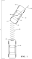
- Figure 1 diagrammatically illustrates a device 20 for tracking a moving object 22.
- the device 20 is situated on a host vehicle 24.
- the moving object 22 is another vehicle located ahead of the host vehicle 24 and at least partially in a pathway of the host vehicle 24.
- the device 20 uses RADAR signaling as schematically shown at 26 for tracking the vehicle 22.
- the vehicle 22 includes a centroid 32.
- the vehicle 22 is traveling along a curved trajectory, such as turning (to the right according to the drawing). Under such conditions, a velocity vector of the centroid 32 of the vehicle 22 is situated at a heading angle 34 under the conditions shown in Figure 1 .
- the coordinate system in which the heading angle 34 is determined may be based upon a world coordinate system. Alternatively, the coordinate system may be fixed relative to the host vehicle 24 or the device 20.
- the pointing angle refers to the body orientation angle of a moving object, such as the vehicle 22, that is being tracked by the device 20.
- the body orientation angle or the pointing angle is the azimuth direction that the moving body's centerline or longitudinal axis is pointing.
- the heading angle is the direction of motion of a particular reference point on the moving object, such as the vehicle 22. It is worth noting that in some contexts, such as aviation, the term “heading angle” is used to refer to that which is called the “pointing angle” in this document. Also, in aviation contexts, the term “track” is used to refer to that which is called the “heading angle” in this document.
- Figure 2 schematically illustrates selected portions of the device 20 including an emitter 42 and detector 44.
- the emitter 42 emits radiation in an outward direction and, when such radiation reflects off of an object, that reflected radiation is received and detected by the detector 44.
- the emitter 42 and detector 44 operate according to known RADAR principles and techniques.
- Other embodiments include emitter and detector configurations that are useful for LIDAR or ultrasonic detection techniques.
- the device 20 includes a filter 46 that is configured for estimating dynamic quantities of a tracked object such as the position, velocity, acceleration, and trajectory curvature of that object.
- the filter 46 operates according to known principles of Kalman filters.
- the filter 46 in this example provides information that indicates the heading angle of at least one reference point on the moving object 22.
- the filter 46 provides information indicating the heading angle 34 of the centroid 32 of the vehicle 22.
- the filter 46 is capable of providing information regarding the heading angle of the centroid of a moving object, however, the filter 46 is not capable of distinguishing between multiple detected points on the object or vehicle 22.
- the detector 44 may receive reflected radiation from a plurality of points A, B, C, D in various locations on the vehicle 22.
- the filter 46 is not able to distinguish between information regarding those detected points A-D and information regarding a single point that is detected multiple times. In other words, the filter 46 will interpret the information, such as the range rate, regarding the points A-D as if that information indicated movement of a single point rather than indicating multiple, different points.
- the filter 46 operates as a Kalman filter, it treats all detected point information as if it pertains to a single point.
- the device 20 includes a processor 50, which may be a dedicated microprocessor or a portion of another computing device supported on the host vehicle 24.
- the processor 50 is configured for determining an estimated heading angle based on position information regarding one or more detected points A-D on the object 22 over time.
- Memory 52 is associated with the processor 50.
- the memory 52 includes computer-executable instructions that cause the processor 50 to operate for purposes of tracking a moving object and determining the pointing angle or body orientation angle of that object.
- the memory 52 at least temporarily contains information regarding various features or characteristics of detected points on the tracked object 22 to facilitate the processor 50 making desired determinations regarding the position or movement of such an object.
- Example embodiments of this invention allow for more accurately determining the heading angle of a moving object, such as the vehicle 22. This feature is particularly useful at the beginning of a tracking session when the filter 46 has relatively limited information for determining the heading angle. With the processor 50 providing a heading angle estimate to the filter 46 object tracking is improved. Embodiments of this invention, therefore, provide an improvement in tracking technology and improvements in vehicle control based on information regarding moving objects in a vicinity or pathway of a vehicle.
- the filter 46 operates to provide an indication of the presence of an object even though the heading angle is not yet defined. This approach allows for early object detection and subsequent determination or refinement of the heading angle.
- Figure 3 is a flow chart diagram 60 summarizing an example method of tracking an object 22 including estimating a heading angle using position information regarding one or more points A-D on the tracked object.
- the detector 44 detects radiation reflected from one or more points on the object 22 over time.
- a plurality of detections over time provides information regarding the object 22 as it moves.
- the processor 50 determines a position of each of the detections, which corresponds to the respective positions of the detected points A-D over time.
- the position information is determined in a world coordinate system.
- the processor 50 determines a relationship between the positions determined at 64.
- the relationship in this example includes relative positions of the detections over an area that defines a shape.
- the determined relationship defines an arc, line or rectangle that encompasses or includes the determined locations.
- the processor determines an orientation of that shape within the world coordinate system and uses that orientation to determine the estimated heading angle of the object at 68. The determination of the heading angle is therefore based on the relationship determined at 66.
- the orientation of the shape defined by the relationship determined at 66 will indicate a path of tracked object movement but not the direction of movement along that path.
- the processor 50 in this example uses range rate information regarding the plurality of detections to determine the direction of movement.
- the processor 50 provides the determined estimated heading angle to the filter 46 at 70.
- the filter 46 will update a previous heading angle determined by the filter 46 based on the estimated heading angle from the processor 50. In some examples the filter 46 will replace the previously determined heading angle with the estimated heading angle from the processor 50.
- the processor 50 Having sufficient detections over time allows the processor 50 to make more accurate estimations of the heading angle.
- the positions of the detections span a distance that exceeds a preselected threshold. Having a sufficiently large distance between the positions of the detections that are furthest apart increases the likelihood that the object 22 has moved sufficiently for the position information determined by the processor 50 to accurately estimate the heading angle. Given this description, those skilled in the art will be able to select an appropriate threshold distance to meet the needs of their particular situation.
- the processor determines the estimated heading angle using one of several techniques.
- a likelihood estimation provides the most likely heading angle based on the positions of the detections.
- ⁇ ) can be sufficiently represented by the orthogonal position of the detection relative to the object centroid, which can be represented as l x t , y t
- ⁇ h o i ⁇ o t ⁇ h o i ′ .
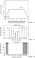
- Figure 4 shows an example of the log-likelihood of a detection as a function of o i ′ .
- the parameters W min and r min are pre-determined.
- the total likelihood is determined by the processor 50 in this example as the sum of individual likelihoods normalized by the number of detections.
- the total likelihood will take a low value if the longitudinal span of the shape determined from the relationship determined at 66 is less than the threshold distance. Detections close to the current object position are preferred over further detections to account for any maneuver of the object 22 at a longer distance. Additionally, when too few detections over time are available, the processor 50 assigns a low value to the total likelihood.
- an example embodiment includes a two-step angle search to find the optimal heading angle ⁇ . Note that it suffices to search inside ⁇ ⁇ [0, ⁇ ], since the likelihood of detection at heading angles ⁇ and ⁇ + ⁇ are the same.
- the two-step angle search is demonstrated by Figures 5 and 6 .
- the respective likelihoods of the detections are first evaluated on a coarse angle grid as shown in Figure 5 . If none of the likelihood exceeds a preselected threshold at 80, the processor 50 will stop the heading angle determination because of insufficient information in the detections. When at least one of the detections satisfies the threshold 80, the processor selects the angle points at which the likelihood is higher than the threshold 80 and establishes a fine angle grid covering the range of these angle points as shown in Figure 6 . Since the heading angles 0, 0.8 ⁇ and 0.9 ⁇ in Figure 5 each exceed the threshold 80, the processor uses those angles as the angles of interest in the fine grid of Figure 6 .
- the resolution in Figure 5 is ⁇ /10 and the resolution in Figure 6 is ⁇ /60.
Landscapes
- Engineering & Computer Science (AREA)
- Physics & Mathematics (AREA)
- Remote Sensing (AREA)
- Radar, Positioning & Navigation (AREA)
- General Physics & Mathematics (AREA)
- Computer Networks & Wireless Communication (AREA)
- Electromagnetism (AREA)
- Theoretical Computer Science (AREA)
- Computer Vision & Pattern Recognition (AREA)
- Geometry (AREA)
- Multimedia (AREA)
- Radar Systems Or Details Thereof (AREA)
- Navigation (AREA)
Description
- Various sensor types have proven useful for detecting objects nearby or in a pathway of a vehicle. Example sensor types include ultrasound, radio detection and ranging (RADAR) and light detection and ranging (LIDAR). The way in which such sensors are being used on passenger vehicles has been increasing.
- One challenge associated with using such sensors for tracking objects is that the objects can have varying shapes and sizes, which impair the ability of a sensor to determine certain characteristics of the object such as the direction in which the object is heading. Known Kalman filters are designed to rapidly provide heading angle or direction information regarding a tracked object. While a Kalman filter estimate is often very useful, it is possible for the estimate to be inaccurate.
- Kalman filters are designed to operate based on tracking movement of a single point. Since three-dimensional objects have multiple points that may be detected by a sensor, the Kalman filter can interpret detector information regarding multiple points as if it indicates movement of a single point. In other words, a Kalman filter is not capable of distinguishing between detection of multiple different points on an object and movement of a single point on that object. Given the possibility of interpreting different points on an object as if they were the same point, sensor information regarding those points can be mistaken for movement of a single point leading to inaccurate tracking information.
-
US 9 014 903 B1 US 2018/095171 A1 a system and method for detecting heading and velocity of a target object is described. Determining a main principle axis of a detected object using some optimization criteria is known from the publication Y S Liu et al. "Robust principal axes determination for point-based shapes using least median of squares ", COMPUTER AIDED DESIGN, ELSEVIER PUBLISHERS BV., BARKING, GB, vol. 41, no. 4, 1 April 2009, pages 293-305, XP026048883, ISSN: 0010-4485, DOI: 10.1016/J.CAD.2008.10.012. Kellner Dominik et al: "Tracking of Extended Objects with High-Resolution Doppler Radar", IEEE TRANSACTIONS ON INTELLIGENT TRANSPORTATION SYSTEMS, IEEE, PISCATAWAY, NJ, USA, vol. 17, no. 5, 1 May 2016, pages 1341-1353, XP011608058, ISSN: 1524-9050, DOI: 10.1109/TITS.2015.2501759 discloses a method for tracking extended objects with high resolution Doppler radar using a velocity profile of the extended objects. The invention is defined in the appended claims. -
Claim 1 defines a method of tracking a moving object proximate a host vehicle includes receiving, with a processor and from a ranging sensor of the host vehicle, a plurality of detections corresponding to multiple points on the moving object over time, determining, with the processor, a position of each of the detections relative to a two-dimensional world coordinate system, and determining, with the processor, an estimated heading angle of the moving object. The estimated heading angle defines a direction of motion of a centroid of the moving object relative to the host vehicle. The estimated heading angle of the moving object is determined by at least: for each of a plurality of candidate heading angles: defining an object body coordinate system for the detections, wherein the object body coordinate system has a same origin as the two-dimensional world coordinate system and a longitudinal axis that is parallel to the respective candidate heading angle, for each of the detections, determining a log-likelihood for the respective detection based on a respective detection's orthogonal position relative to the centroid in the object body coordinate system for the respective candidate heading angle; determining an overall log-likelihood for the respective candidate heading angle based on the log-likelihoods of the detections determined for the respective candidate heading angle; and selecting the estimated heading angle from the candidate heading angles based on the respective overall log-likelihoods for the candidate heading angles. - Claim 11 defines a device for tracking a moving object proximate a host vehicle includes a processor that is configured to perform the method of any of the previous paragraphs.
- Optional features are defined in the dependent claims.
- The various features and advantages of the embodiments according to the claimed invention will become apparent to those skilled in the art from the following detailed description. The drawings that accompany the detailed description can be briefly described as follows.
-
-
Figure 1 diagrammatically illustrates an example use of a device for tracking an object. -
Figure 2 schematically illustrates selected portions of an example object tracking device. -
Figure 3 is a flowchart diagram summarizing an example method of tracking an object. -
Figure 4 graphically illustrates a log-likelihood function used in an example embodiment. -
Figure 5 graphically illustrates an angle grid used for determining an object heading angle in an example embodiment. -
Figure 6 illustrates another example angle grid that has finer resolution compared to the grid shown inFigure 5 . -
Figure 1 diagrammatically illustrates adevice 20 for tracking amoving object 22. In this example, thedevice 20 is situated on ahost vehicle 24. For discussion purposes, themoving object 22 is another vehicle located ahead of thehost vehicle 24 and at least partially in a pathway of thehost vehicle 24. Thedevice 20 uses RADAR signaling as schematically shown at 26 for tracking thevehicle 22. - As schematically shown in
Figure 1 , thevehicle 22 includes acentroid 32. Thevehicle 22 is traveling along a curved trajectory, such as turning (to the right according to the drawing). Under such conditions, a velocity vector of thecentroid 32 of thevehicle 22 is situated at aheading angle 34 under the conditions shown inFigure 1 . The coordinate system in which theheading angle 34 is determined may be based upon a world coordinate system. Alternatively, the coordinate system may be fixed relative to thehost vehicle 24 or thedevice 20. - In this document, the pointing angle refers to the body orientation angle of a moving object, such as the
vehicle 22, that is being tracked by thedevice 20. The body orientation angle or the pointing angle is the azimuth direction that the moving body's centerline or longitudinal axis is pointing. - In this document, the heading angle is the direction of motion of a particular reference point on the moving object, such as the
vehicle 22. It is worth noting that in some contexts, such as aviation, the term "heading angle" is used to refer to that which is called the "pointing angle" in this document. Also, in aviation contexts, the term "track" is used to refer to that which is called the "heading angle" in this document. -
Figure 2 schematically illustrates selected portions of thedevice 20 including anemitter 42 anddetector 44. Theemitter 42 emits radiation in an outward direction and, when such radiation reflects off of an object, that reflected radiation is received and detected by thedetector 44. In some example embodiments, theemitter 42 anddetector 44 operate according to known RADAR principles and techniques. Other embodiments include emitter and detector configurations that are useful for LIDAR or ultrasonic detection techniques. - The
device 20 includes afilter 46 that is configured for estimating dynamic quantities of a tracked object such as the position, velocity, acceleration, and trajectory curvature of that object. In some example embodiments, thefilter 46 operates according to known principles of Kalman filters. Thefilter 46 in this example provides information that indicates the heading angle of at least one reference point on themoving object 22. For example, thefilter 46 provides information indicating theheading angle 34 of thecentroid 32 of thevehicle 22. - The
filter 46 is capable of providing information regarding the heading angle of the centroid of a moving object, however, thefilter 46 is not capable of distinguishing between multiple detected points on the object orvehicle 22. For example, inFigure 1 , thedetector 44 may receive reflected radiation from a plurality of points A, B, C, D in various locations on thevehicle 22. Thefilter 46 is not able to distinguish between information regarding those detected points A-D and information regarding a single point that is detected multiple times. In other words, thefilter 46 will interpret the information, such as the range rate, regarding the points A-D as if that information indicated movement of a single point rather than indicating multiple, different points. When thefilter 46 operates as a Kalman filter, it treats all detected point information as if it pertains to a single point. - The
device 20 includes aprocessor 50, which may be a dedicated microprocessor or a portion of another computing device supported on thehost vehicle 24. In this embodiment, theprocessor 50 is configured for determining an estimated heading angle based on position information regarding one or more detected points A-D on theobject 22 over time. -
Memory 52 is associated with theprocessor 50. In some example embodiments, thememory 52 includes computer-executable instructions that cause theprocessor 50 to operate for purposes of tracking a moving object and determining the pointing angle or body orientation angle of that object. In some example embodiments, thememory 52 at least temporarily contains information regarding various features or characteristics of detected points on the trackedobject 22 to facilitate theprocessor 50 making desired determinations regarding the position or movement of such an object. - Example embodiments of this invention allow for more accurately determining the heading angle of a moving object, such as the
vehicle 22. This feature is particularly useful at the beginning of a tracking session when thefilter 46 has relatively limited information for determining the heading angle. With theprocessor 50 providing a heading angle estimate to thefilter 46 object tracking is improved. Embodiments of this invention, therefore, provide an improvement in tracking technology and improvements in vehicle control based on information regarding moving objects in a vicinity or pathway of a vehicle. - In some embodiments, the
filter 46 operates to provide an indication of the presence of an object even though the heading angle is not yet defined. This approach allows for early object detection and subsequent determination or refinement of the heading angle. -
Figure 3 is a flow chart diagram 60 summarizing an example method of tracking anobject 22 including estimating a heading angle using position information regarding one or more points A-D on the tracked object. At 62 thedetector 44 detects radiation reflected from one or more points on theobject 22 over time. A plurality of detections over time provides information regarding theobject 22 as it moves. At 64, theprocessor 50 determines a position of each of the detections, which corresponds to the respective positions of the detected points A-D over time. In this example, the position information is determined in a world coordinate system. - At 66, the
processor 50 determines a relationship between the positions determined at 64. The relationship in this example includes relative positions of the detections over an area that defines a shape. For example, the determined relationship defines an arc, line or rectangle that encompasses or includes the determined locations. The processor determines an orientation of that shape within the world coordinate system and uses that orientation to determine the estimated heading angle of the object at 68. The determination of the heading angle is therefore based on the relationship determined at 66. - In some situations, the orientation of the shape defined by the relationship determined at 66 will indicate a path of tracked object movement but not the direction of movement along that path. The
processor 50 in this example uses range rate information regarding the plurality of detections to determine the direction of movement. - The
processor 50 provides the determined estimated heading angle to thefilter 46 at 70. Thefilter 46 will update a previous heading angle determined by thefilter 46 based on the estimated heading angle from theprocessor 50. In some examples thefilter 46 will replace the previously determined heading angle with the estimated heading angle from theprocessor 50. - Having sufficient detections over time allows the
processor 50 to make more accurate estimations of the heading angle. In the example embodiment, the positions of the detections span a distance that exceeds a preselected threshold. Having a sufficiently large distance between the positions of the detections that are furthest apart increases the likelihood that theobject 22 has moved sufficiently for the position information determined by theprocessor 50 to accurately estimate the heading angle. Given this description, those skilled in the art will be able to select an appropriate threshold distance to meet the needs of their particular situation. - The processor determines the estimated heading angle using one of several techniques. In one embodiment a likelihood estimation provides the most likely heading angle based on the positions of the detections.
- Suppose there are N detections with positions x = [x 1, ... , xN ] and y = [y 1, ... , yN ] in a world coordinate system. The log-likelihood of detections l( x , y |θ) at a heading angle θ roughly describes how well the detection trace can fit a trajectory with a heading angle θ. This embodiment includes an assumption that each detection has uniform position likelihood inside the
object 22. Due to angle errors in the detections, the likelihood of a detection's position being outside theobject 22 gradually decreases to zero as it gets further away from theobject 22. - This example includes defining the object body coordinate system such that its longitudinal axis is parallel to the
object heading angle 34, and its origin is the same as the origin of world coordinate. If an object track has a centroid (xt , yt ) in world coordinates, its centroid position in the object body coordinate system is
- The position of a detection (xi , yi ) in the object body coordinate system is

- The log-likelihood of a single detection l(xt , yt |θ) can be sufficiently represented by the orthogonal position of the detection relative to the object centroid, which can be represented as

-
Figure 4 shows an example of the log-likelihood of a detection as a function of
plot 74 can depend on the object pose, object range, and the nominal standard deviation of angle error in detections. It follows that
vehicle 24, r is the object range, and e is the nominal standard deviation of angle error in the detections. The parameters Wmin and rmin are pre-determined. - Assuming independence between multiple detections, the overall log-likelihood can be written as

- The total likelihood is determined by the
processor 50 in this example as the sum of individual likelihoods normalized by the number of detections. In one example embodiment, the total likelihood will take a low value if the longitudinal span of the shape determined from the relationship determined at 66 is less than the threshold distance. Detections close to the current object position are preferred over further detections to account for any maneuver of theobject 22 at a longer distance. Additionally, when too few detections over time are available, theprocessor 50 assigns a low value to the total likelihood. - The maximum likelihood estimation of the heading angle can be obtained by solving:

- That optimization equation cannot be analytically solved. For numerically solving such problem, an example embodiment includes a two-step angle search to find the optimal heading angle π. Note that it suffices to search inside θ ∈ [0,π], since the likelihood of detection at heading angles θ and θ + π are the same.
- The two-step angle search is demonstrated by
Figures 5 and 6 . The respective likelihoods of the detections are first evaluated on a coarse angle grid as shown inFigure 5 . If none of the likelihood exceeds a preselected threshold at 80, theprocessor 50 will stop the heading angle determination because of insufficient information in the detections. When at least one of the detections satisfies thethreshold 80, the processor selects the angle points at which the likelihood is higher than thethreshold 80 and establishes a fine angle grid covering the range of these angle points as shown inFigure 6 . Since the heading angles 0, 0.8π and 0.9π inFigure 5 each exceed thethreshold 80, the processor uses those angles as the angles of interest in the fine grid ofFigure 6 . The resolution inFigure 5 is π/10 and the resolution inFigure 6 is π/60. - As can be appreciated from the illustration, a plurality of candidate angles surrounding the
angles 0, 0.8π and 0.9π are evaluated by theprocessor 50. The optimal heading angle among those candidates that maximizes the likelihood is selected as the estimated heading angle π in this example. The scope of legal protection given to this invention can only be determined by studying the following claims.
Claims (12)
- A method of tracking a moving object (22) proximate a host vehicle (24), the method comprising:receiving, with a processor (50) and from a ranging sensor of the host vehicle, a plurality of detections corresponding to multiple points on the moving object (22) over time;determining, with the processor (50), a position of each of the detections relative to a two-dimensional world coordinate system; anddetermining, with the processor (50), an estimated heading angle (34) of the moving object (22), the estimated heading angle (34) defining a direction of motion of a centroid (32) of the moving object (22) relative to the host vehicle (24), the estimated heading angle (34) of the moving object (22) determined by at least:
for each of a plurality of candidate heading angles:defining an object body coordinate system for the detections, the object body coordinate system having a same origin as the two-dimensional world coordinate system and a longitudinal axis that is parallel to the respective candidate heading angle; characterized byfor each of the detections, determining a log-likelihood for the respective detection based on a respective detection's orthogonal position relative to the centroid (32) in the object body coordinate system for the respective candidate heading angle;determining an overall log-likelihood for the respective candidate heading angle based on the log-likelihoods of the detections determined for the respective candidate heading angle; andselecting the estimated heading angle (34) from the candidate heading angles based on the respective overall log-likelihoods for the candidate heading angles. - The method of claim 1, further comprising
detecting the multiple points at least until a distance spanned by the determined positions exceeds a preselected threshold distance. - The method of any one of the previous claims, further comprising
using the determined estimated heading angle (34) to correct a previously estimated heading angle (34) of the object (22). - The method of claim 3, wherein the previously estimated heading angle (34) of the object (22) is determined by a Kalman filter.
- The method of any one of the previous claims,wherein the estimated heading angle (34) is further determined by:selecting one or more coarse heading angles based on overall log-likelihoods for a plurality of candidate coarse heading angles;selecting a fine heading angle based on overall log-likelihoods for a plurality of candidate fine heading angles near the selected coarse heading angles,wherein the estimated heading angle (34) comprises the fine heading angle.
- The method of claim 5,
wherein the selected coarse heading angles have log-likelihoods exceed a preselected threshold (80). - The method of any one of the previous claims,
wherein the overall log-likelihood for the respective candidate heading angle comprises a sum of the log-likelihoods of the detections determined for the respective candidate heading angle. - The method of any one of the previous claims,
wherein selecting the estimated heading angle (34) comprises selecting a candidate heading angle with a maximum overall log-likelihood. - The method of any one of the previous claims,
wherein the estimated heading angle (34) is further determined by:for each of the candidate heading angles, determining a total likelihood based on the log-likelihoods of the detections determined for the respective candidate heading angle; andselecting the estimated heading angle (34) based on the total likelihood passing a threshold (80). - The method of claim 9,
wherein the total likelihood comprises the overall log-likelihood normalized by a number of the detections. - A device (20) for tracking a moving object (22) proximate a host vehicle (24), the device (20) comprising:
a processor (50) that is configured to perform the method of any one of the previous claims. - The device (20) of claim 11, further comprising a ranging sensor.
Applications Claiming Priority (1)
| Application Number | Priority Date | Filing Date | Title |
|---|---|---|---|
| US16/398,745 US11113824B2 (en) | 2019-04-30 | 2019-04-30 | Heading angle estimation for object tracking |
Publications (2)
| Publication Number | Publication Date |
|---|---|
| EP3734327A1 EP3734327A1 (en) | 2020-11-04 |
| EP3734327B1 true EP3734327B1 (en) | 2024-06-19 |
Family
ID=70058269
Family Applications (1)
| Application Number | Title | Priority Date | Filing Date |
|---|---|---|---|
| EP20166800.1A Active EP3734327B1 (en) | 2019-04-30 | 2020-03-30 | Heading angle estimation for object tracking |
Country Status (3)
| Country | Link |
|---|---|
| US (2) | US11113824B2 (en) |
| EP (1) | EP3734327B1 (en) |
| CN (1) | CN111856443B (en) |
Families Citing this family (5)
| Publication number | Priority date | Publication date | Assignee | Title |
|---|---|---|---|---|
| US11113824B2 (en) | 2019-04-30 | 2021-09-07 | Aptiv Technologies Limited | Heading angle estimation for object tracking |
| CN114625128B (en) * | 2022-02-21 | 2024-08-27 | 武汉理工大学 | An algorithm for estimating the heading angle of the path to be tracked by an unmanned system |
| KR20230135262A (en) * | 2022-03-16 | 2023-09-25 | 주식회사 에이치엘클레무브 | Radar appartus and control method thereof, driver assistance system having it |
| KR102739234B1 (en) * | 2022-10-17 | 2024-12-05 | 주식회사 에이치엘클레무브 | Radar control apparatus and method |
| US12560711B2 (en) * | 2023-08-28 | 2026-02-24 | International Business Machines Corporation | Auditory-based environment monitoring |
Family Cites Families (38)
| Publication number | Priority date | Publication date | Assignee | Title |
|---|---|---|---|---|
| EP0662600A4 (en) * | 1993-06-10 | 1997-02-12 | Oh Yoh Keisoku Kenkyusho Kk | Apparatus for measuring position of moving object. |
| US6891563B2 (en) * | 1996-05-22 | 2005-05-10 | Donnelly Corporation | Vehicular vision system |
| US5964822A (en) | 1997-08-27 | 1999-10-12 | Delco Electronics Corp. | Automatic sensor azimuth alignment |
| US6292759B1 (en) | 1998-11-19 | 2001-09-18 | Delphi Technologies, Inc. | Vehicle attitude angle estimation using sensed signal blending |
| JP4488547B2 (en) * | 1999-04-06 | 2010-06-23 | 三井造船株式会社 | Floating rig position holding control method and control apparatus |
| DE10036042B4 (en) * | 2000-07-25 | 2004-12-16 | Daimlerchrysler Ag | Multisensorial lane assignment |
| JP4161573B2 (en) * | 2001-06-29 | 2008-10-08 | 株式会社豊田自動織機 | Parking assistance device |
| US6615138B1 (en) | 2002-05-30 | 2003-09-02 | Delphi Technologies, Inc. | Collision detection system and method of estimating miss distance employing curve fitting |
| US6794987B2 (en) | 2002-07-01 | 2004-09-21 | Delphi Technologies, Inc. | Object detection system and method of estimating object size |
| JP4700899B2 (en) * | 2003-04-14 | 2011-06-15 | 株式会社豊田自動織機 | Parking assistance device |
| JP2004322787A (en) * | 2003-04-23 | 2004-11-18 | Nissan Motor Co Ltd | Lane departure prevention device |
| JP3818653B2 (en) * | 2003-06-26 | 2006-09-06 | トヨタ自動車株式会社 | Vehicle travel support device |
| DE102004018205A1 (en) * | 2004-04-15 | 2005-11-10 | Robert Bosch Gmbh | Device for assisting a parking process of a vehicle |
| US7057500B1 (en) * | 2004-04-23 | 2006-06-06 | Belloso Gregorio M | Rear view monitoring system for motor vehicles |
| JP4042980B2 (en) * | 2004-05-14 | 2008-02-06 | 本田技研工業株式会社 | Vehicle operation support device |
| US7792622B2 (en) * | 2005-07-01 | 2010-09-07 | Deere & Company | Method and system for vehicular guidance using a crop image |
| KR100761011B1 (en) * | 2006-05-30 | 2007-09-21 | 학교법인 인하학원 | Posture Correction Apparatus and Method for Inertial Navigation System Using Camera-type Solar Sensor |
| JP4497133B2 (en) * | 2006-07-12 | 2010-07-07 | アイシン・エィ・ダブリュ株式会社 | Driving support method and driving support device |
| JP4420002B2 (en) * | 2006-09-14 | 2010-02-24 | トヨタ自動車株式会社 | Eye-gaze estimation device |
| EP2302407B1 (en) * | 2006-11-06 | 2012-08-29 | TomTom Global Content B.V. | Arrangement for and method of two dimensional and three dimensional precision location and orientation determination. |
| JP5187154B2 (en) * | 2008-03-21 | 2013-04-24 | 日産自動車株式会社 | Lane departure prevention apparatus and lane departure prevention method |
| TW201103787A (en) * | 2009-07-31 | 2011-02-01 | Automotive Res & Testing Ct | Obstacle determination system and method utilizing bird's-eye images |
| JP5363920B2 (en) * | 2009-08-31 | 2013-12-11 | 富士重工業株式会社 | Vehicle white line recognition device |
| JP5742465B2 (en) * | 2010-05-25 | 2015-07-01 | リコーイメージング株式会社 | Astronomical auto tracking imaging method and astronomical auto tracking imaging device |
| JP5618744B2 (en) * | 2010-05-26 | 2014-11-05 | 三菱電機株式会社 | Road shape estimation apparatus, computer program, and road shape estimation method |
| JP5503419B2 (en) * | 2010-06-03 | 2014-05-28 | 株式会社日立製作所 | Automated guided vehicle and travel control method |
| US9102269B2 (en) * | 2011-08-09 | 2015-08-11 | Continental Automotive Systems, Inc. | Field of view matching video display system |
| US9014903B1 (en) | 2012-05-22 | 2015-04-21 | Google Inc. | Determination of object heading based on point cloud |
| KR101252015B1 (en) * | 2012-08-16 | 2013-04-09 | 주식회사 피엘케이 테크놀로지 | Navigation system for judging route change of vehicle |
| KR20140044964A (en) * | 2012-09-07 | 2014-04-16 | 주식회사 만도 | Apparatus for calculating distance between vehicles and method for calculating distance thereof |
| US8930060B1 (en) * | 2013-07-15 | 2015-01-06 | Ford Global Technologies | Post-impact path assist for vehicles |
| US9921306B1 (en) | 2015-05-27 | 2018-03-20 | Lockheed Martin Corporation | Active optimal reduced state estimator |
| US10089875B2 (en) | 2016-09-06 | 2018-10-02 | Delphi Technologies, Inc. | Automated vehicle cross-traffic detection system |
| US10222472B2 (en) | 2016-09-30 | 2019-03-05 | Veoneer Us, Inc. | System and method for detecting heading and velocity of a target object |
| EP3422042B1 (en) * | 2017-06-29 | 2020-03-18 | Aptiv Technologies Limited | Method to determine the orientation of a target vehicle |
| US10948583B2 (en) | 2018-10-23 | 2021-03-16 | Valeo Radar Systems, Inc. | Radar track initialization |
| US11113824B2 (en) | 2019-04-30 | 2021-09-07 | Aptiv Technologies Limited | Heading angle estimation for object tracking |
| EP3904907A1 (en) | 2020-04-29 | 2021-11-03 | Aptiv Technologies Limited | Methods and systems for tracking an object |
-
2019
- 2019-04-30 US US16/398,745 patent/US11113824B2/en active Active
-
2020
- 2020-03-30 EP EP20166800.1A patent/EP3734327B1/en active Active
- 2020-04-29 CN CN202010355442.3A patent/CN111856443B/en active Active
-
2021
- 2021-08-16 US US17/403,690 patent/US11615538B2/en active Active
Also Published As
| Publication number | Publication date |
|---|---|
| US11113824B2 (en) | 2021-09-07 |
| CN111856443B (en) | 2024-12-31 |
| EP3734327A1 (en) | 2020-11-04 |
| US20200349718A1 (en) | 2020-11-05 |
| US20210374974A1 (en) | 2021-12-02 |
| US11615538B2 (en) | 2023-03-28 |
| CN111856443A (en) | 2020-10-30 |
Similar Documents
| Publication | Publication Date | Title |
|---|---|---|
| US11615538B2 (en) | Heading angle estimation for object tracking | |
| US10677907B2 (en) | Method to determine the orientation of a target vehicle | |
| CN104554272B (en) | The path planning of avoidance steering operation when target vehicle and surrounding objects be present | |
| US11373533B2 (en) | Vehicle control apparatus | |
| CN104554258B (en) | Using the path planning of the avoidance steering operation of virtual potential field technology | |
| US11536822B2 (en) | Radar device | |
| JP2024169478A (en) | Output device, control method, program, and storage medium | |
| EP3751459A1 (en) | Adjusting velocity of a vehicle for a curve | |
| CN110888115B (en) | Classify potentially stationary objects tracked by radar | |
| US11156466B2 (en) | Lane determination device | |
| US10482332B2 (en) | Pedestrian determining apparatus for determining whether an object is a pedestrian crossing ahead of an own vehicle | |
| US10816344B2 (en) | Method and system for determining the pointing angle of a moving object | |
| CN110244293B (en) | Method and system for determining pointing angle of moving object | |
| JP6740470B2 (en) | Measuring device, measuring method and program | |
| CN108146410A (en) | Automatic breaking system | |
| US10914832B2 (en) | Estimation apparatus | |
| CN114556141A (en) | Object tracking device | |
| US12332347B2 (en) | Method for operating radar sensors | |
| JP2024038322A (en) | Measuring device, measuring method and program | |
| WO2018212283A1 (en) | Measurement device, measurement method and program |
Legal Events
| Date | Code | Title | Description |
|---|---|---|---|
| PUAI | Public reference made under article 153(3) epc to a published international application that has entered the european phase |
Free format text: ORIGINAL CODE: 0009012 |
|
| STAA | Information on the status of an ep patent application or granted ep patent |
Free format text: STATUS: THE APPLICATION HAS BEEN PUBLISHED |
|
| AK | Designated contracting states |
Kind code of ref document: A1 Designated state(s): AL AT BE BG CH CY CZ DE DK EE ES FI FR GB GR HR HU IE IS IT LI LT LU LV MC MK MT NL NO PL PT RO RS SE SI SK SM TR |
|
| AX | Request for extension of the european patent |
Extension state: BA ME |
|
| STAA | Information on the status of an ep patent application or granted ep patent |
Free format text: STATUS: REQUEST FOR EXAMINATION WAS MADE |
|
| 17P | Request for examination filed |
Effective date: 20210429 |
|
| RBV | Designated contracting states (corrected) |
Designated state(s): AL AT BE BG CH CY CZ DE DK EE ES FI FR GB GR HR HU IE IS IT LI LT LU LV MC MK MT NL NO PL PT RO RS SE SI SK SM TR |
|
| STAA | Information on the status of an ep patent application or granted ep patent |
Free format text: STATUS: EXAMINATION IS IN PROGRESS |
|
| 17Q | First examination report despatched |
Effective date: 20220831 |
|
| RAP3 | Party data changed (applicant data changed or rights of an application transferred) |
Owner name: APTIV TECHNOLOGIES LIMITED |
|
| GRAP | Despatch of communication of intention to grant a patent |
Free format text: ORIGINAL CODE: EPIDOSNIGR1 |
|
| STAA | Information on the status of an ep patent application or granted ep patent |
Free format text: STATUS: GRANT OF PATENT IS INTENDED |
|
| INTG | Intention to grant announced |
Effective date: 20240215 |
|
| RAP1 | Party data changed (applicant data changed or rights of an application transferred) |
Owner name: APTIV TECHNOLOGIES AG |
|
| P01 | Opt-out of the competence of the unified patent court (upc) registered |
Effective date: 20240402 |
|
| GRAS | Grant fee paid |
Free format text: ORIGINAL CODE: EPIDOSNIGR3 |
|
| GRAA | (expected) grant |
Free format text: ORIGINAL CODE: 0009210 |
|
| STAA | Information on the status of an ep patent application or granted ep patent |
Free format text: STATUS: THE PATENT HAS BEEN GRANTED |
|
| AK | Designated contracting states |
Kind code of ref document: B1 Designated state(s): AL AT BE BG CH CY CZ DE DK EE ES FI FR GB GR HR HU IE IS IT LI LT LU LV MC MK MT NL NO PL PT RO RS SE SI SK SM TR |
|
| REG | Reference to a national code |
Ref country code: GB Ref legal event code: FG4D |
|
| REG | Reference to a national code |
Ref country code: CH Ref legal event code: EP |
|
| REG | Reference to a national code |
Ref country code: DE Ref legal event code: R096 Ref document number: 602020032530 Country of ref document: DE |
|
| RAP4 | Party data changed (patent owner data changed or rights of a patent transferred) |
Owner name: APTIV TECHNOLOGIES AG |
|
| PG25 | Lapsed in a contracting state [announced via postgrant information from national office to epo] |
Ref country code: BG Free format text: LAPSE BECAUSE OF FAILURE TO SUBMIT A TRANSLATION OF THE DESCRIPTION OR TO PAY THE FEE WITHIN THE PRESCRIBED TIME-LIMIT Effective date: 20240619 |
|
| PG25 | Lapsed in a contracting state [announced via postgrant information from national office to epo] |
Ref country code: FI Free format text: LAPSE BECAUSE OF FAILURE TO SUBMIT A TRANSLATION OF THE DESCRIPTION OR TO PAY THE FEE WITHIN THE PRESCRIBED TIME-LIMIT Effective date: 20240619 Ref country code: HR Free format text: LAPSE BECAUSE OF FAILURE TO SUBMIT A TRANSLATION OF THE DESCRIPTION OR TO PAY THE FEE WITHIN THE PRESCRIBED TIME-LIMIT Effective date: 20240619 |
|
| REG | Reference to a national code |
Ref country code: LT Ref legal event code: MG9D |
|
| PG25 | Lapsed in a contracting state [announced via postgrant information from national office to epo] |
Ref country code: GR Free format text: LAPSE BECAUSE OF FAILURE TO SUBMIT A TRANSLATION OF THE DESCRIPTION OR TO PAY THE FEE WITHIN THE PRESCRIBED TIME-LIMIT Effective date: 20240920 |
|
| REG | Reference to a national code |
Ref country code: NL Ref legal event code: MP Effective date: 20240619 |
|
| PG25 | Lapsed in a contracting state [announced via postgrant information from national office to epo] |
Ref country code: LV Free format text: LAPSE BECAUSE OF FAILURE TO SUBMIT A TRANSLATION OF THE DESCRIPTION OR TO PAY THE FEE WITHIN THE PRESCRIBED TIME-LIMIT Effective date: 20240619 |
|
| PG25 | Lapsed in a contracting state [announced via postgrant information from national office to epo] |
Ref country code: NO Free format text: LAPSE BECAUSE OF FAILURE TO SUBMIT A TRANSLATION OF THE DESCRIPTION OR TO PAY THE FEE WITHIN THE PRESCRIBED TIME-LIMIT Effective date: 20240919 Ref country code: LV Free format text: LAPSE BECAUSE OF FAILURE TO SUBMIT A TRANSLATION OF THE DESCRIPTION OR TO PAY THE FEE WITHIN THE PRESCRIBED TIME-LIMIT Effective date: 20240619 Ref country code: HR Free format text: LAPSE BECAUSE OF FAILURE TO SUBMIT A TRANSLATION OF THE DESCRIPTION OR TO PAY THE FEE WITHIN THE PRESCRIBED TIME-LIMIT Effective date: 20240619 Ref country code: GR Free format text: LAPSE BECAUSE OF FAILURE TO SUBMIT A TRANSLATION OF THE DESCRIPTION OR TO PAY THE FEE WITHIN THE PRESCRIBED TIME-LIMIT Effective date: 20240920 Ref country code: FI Free format text: LAPSE BECAUSE OF FAILURE TO SUBMIT A TRANSLATION OF THE DESCRIPTION OR TO PAY THE FEE WITHIN THE PRESCRIBED TIME-LIMIT Effective date: 20240619 Ref country code: BG Free format text: LAPSE BECAUSE OF FAILURE TO SUBMIT A TRANSLATION OF THE DESCRIPTION OR TO PAY THE FEE WITHIN THE PRESCRIBED TIME-LIMIT Effective date: 20240619 Ref country code: RS Free format text: LAPSE BECAUSE OF FAILURE TO SUBMIT A TRANSLATION OF THE DESCRIPTION OR TO PAY THE FEE WITHIN THE PRESCRIBED TIME-LIMIT Effective date: 20240919 |
|
| PG25 | Lapsed in a contracting state [announced via postgrant information from national office to epo] |
Ref country code: NL Free format text: LAPSE BECAUSE OF FAILURE TO SUBMIT A TRANSLATION OF THE DESCRIPTION OR TO PAY THE FEE WITHIN THE PRESCRIBED TIME-LIMIT Effective date: 20240619 |
|
| REG | Reference to a national code |
Ref country code: AT Ref legal event code: MK05 Ref document number: 1696257 Country of ref document: AT Kind code of ref document: T Effective date: 20240619 |
|
| PG25 | Lapsed in a contracting state [announced via postgrant information from national office to epo] |
Ref country code: NL Free format text: LAPSE BECAUSE OF FAILURE TO SUBMIT A TRANSLATION OF THE DESCRIPTION OR TO PAY THE FEE WITHIN THE PRESCRIBED TIME-LIMIT Effective date: 20240619 |
|
| PG25 | Lapsed in a contracting state [announced via postgrant information from national office to epo] |
Ref country code: PT Free format text: LAPSE BECAUSE OF FAILURE TO SUBMIT A TRANSLATION OF THE DESCRIPTION OR TO PAY THE FEE WITHIN THE PRESCRIBED TIME-LIMIT Effective date: 20241021 |
|
| PG25 | Lapsed in a contracting state [announced via postgrant information from national office to epo] |
Ref country code: PT Free format text: LAPSE BECAUSE OF FAILURE TO SUBMIT A TRANSLATION OF THE DESCRIPTION OR TO PAY THE FEE WITHIN THE PRESCRIBED TIME-LIMIT Effective date: 20241021 |
|
| PG25 | Lapsed in a contracting state [announced via postgrant information from national office to epo] |
Ref country code: PL Free format text: LAPSE BECAUSE OF FAILURE TO SUBMIT A TRANSLATION OF THE DESCRIPTION OR TO PAY THE FEE WITHIN THE PRESCRIBED TIME-LIMIT Effective date: 20240619 |
|
| PG25 | Lapsed in a contracting state [announced via postgrant information from national office to epo] |
Ref country code: EE Free format text: LAPSE BECAUSE OF FAILURE TO SUBMIT A TRANSLATION OF THE DESCRIPTION OR TO PAY THE FEE WITHIN THE PRESCRIBED TIME-LIMIT Effective date: 20240619 |
|
| PG25 | Lapsed in a contracting state [announced via postgrant information from national office to epo] |
Ref country code: IS Free format text: LAPSE BECAUSE OF FAILURE TO SUBMIT A TRANSLATION OF THE DESCRIPTION OR TO PAY THE FEE WITHIN THE PRESCRIBED TIME-LIMIT Effective date: 20241019 Ref country code: AT Free format text: LAPSE BECAUSE OF FAILURE TO SUBMIT A TRANSLATION OF THE DESCRIPTION OR TO PAY THE FEE WITHIN THE PRESCRIBED TIME-LIMIT Effective date: 20240619 |
|
| PG25 | Lapsed in a contracting state [announced via postgrant information from national office to epo] |
Ref country code: CZ Free format text: LAPSE BECAUSE OF FAILURE TO SUBMIT A TRANSLATION OF THE DESCRIPTION OR TO PAY THE FEE WITHIN THE PRESCRIBED TIME-LIMIT Effective date: 20240619 |
|
| PG25 | Lapsed in a contracting state [announced via postgrant information from national office to epo] |
Ref country code: SK Free format text: LAPSE BECAUSE OF FAILURE TO SUBMIT A TRANSLATION OF THE DESCRIPTION OR TO PAY THE FEE WITHIN THE PRESCRIBED TIME-LIMIT Effective date: 20240619 Ref country code: RO Free format text: LAPSE BECAUSE OF FAILURE TO SUBMIT A TRANSLATION OF THE DESCRIPTION OR TO PAY THE FEE WITHIN THE PRESCRIBED TIME-LIMIT Effective date: 20240619 |
|
| PG25 | Lapsed in a contracting state [announced via postgrant information from national office to epo] |
Ref country code: ES Free format text: LAPSE BECAUSE OF FAILURE TO SUBMIT A TRANSLATION OF THE DESCRIPTION OR TO PAY THE FEE WITHIN THE PRESCRIBED TIME-LIMIT Effective date: 20240619 Ref country code: SM Free format text: LAPSE BECAUSE OF FAILURE TO SUBMIT A TRANSLATION OF THE DESCRIPTION OR TO PAY THE FEE WITHIN THE PRESCRIBED TIME-LIMIT Effective date: 20240619 |
|
| PG25 | Lapsed in a contracting state [announced via postgrant information from national office to epo] |
Ref country code: SM Free format text: LAPSE BECAUSE OF FAILURE TO SUBMIT A TRANSLATION OF THE DESCRIPTION OR TO PAY THE FEE WITHIN THE PRESCRIBED TIME-LIMIT Effective date: 20240619 Ref country code: SK Free format text: LAPSE BECAUSE OF FAILURE TO SUBMIT A TRANSLATION OF THE DESCRIPTION OR TO PAY THE FEE WITHIN THE PRESCRIBED TIME-LIMIT Effective date: 20240619 Ref country code: RO Free format text: LAPSE BECAUSE OF FAILURE TO SUBMIT A TRANSLATION OF THE DESCRIPTION OR TO PAY THE FEE WITHIN THE PRESCRIBED TIME-LIMIT Effective date: 20240619 Ref country code: PL Free format text: LAPSE BECAUSE OF FAILURE TO SUBMIT A TRANSLATION OF THE DESCRIPTION OR TO PAY THE FEE WITHIN THE PRESCRIBED TIME-LIMIT Effective date: 20240619 Ref country code: IS Free format text: LAPSE BECAUSE OF FAILURE TO SUBMIT A TRANSLATION OF THE DESCRIPTION OR TO PAY THE FEE WITHIN THE PRESCRIBED TIME-LIMIT Effective date: 20241019 Ref country code: ES Free format text: LAPSE BECAUSE OF FAILURE TO SUBMIT A TRANSLATION OF THE DESCRIPTION OR TO PAY THE FEE WITHIN THE PRESCRIBED TIME-LIMIT Effective date: 20240619 Ref country code: EE Free format text: LAPSE BECAUSE OF FAILURE TO SUBMIT A TRANSLATION OF THE DESCRIPTION OR TO PAY THE FEE WITHIN THE PRESCRIBED TIME-LIMIT Effective date: 20240619 Ref country code: CZ Free format text: LAPSE BECAUSE OF FAILURE TO SUBMIT A TRANSLATION OF THE DESCRIPTION OR TO PAY THE FEE WITHIN THE PRESCRIBED TIME-LIMIT Effective date: 20240619 Ref country code: AT Free format text: LAPSE BECAUSE OF FAILURE TO SUBMIT A TRANSLATION OF THE DESCRIPTION OR TO PAY THE FEE WITHIN THE PRESCRIBED TIME-LIMIT Effective date: 20240619 |
|
| PG25 | Lapsed in a contracting state [announced via postgrant information from national office to epo] |
Ref country code: IT Free format text: LAPSE BECAUSE OF FAILURE TO SUBMIT A TRANSLATION OF THE DESCRIPTION OR TO PAY THE FEE WITHIN THE PRESCRIBED TIME-LIMIT Effective date: 20240619 |
|
| REG | Reference to a national code |
Ref country code: DE Ref legal event code: R097 Ref document number: 602020032530 Country of ref document: DE |
|
| PG25 | Lapsed in a contracting state [announced via postgrant information from national office to epo] |
Ref country code: DK Free format text: LAPSE BECAUSE OF FAILURE TO SUBMIT A TRANSLATION OF THE DESCRIPTION OR TO PAY THE FEE WITHIN THE PRESCRIBED TIME-LIMIT Effective date: 20240619 |
|
| PLBE | No opposition filed within time limit |
Free format text: ORIGINAL CODE: 0009261 |
|
| STAA | Information on the status of an ep patent application or granted ep patent |
Free format text: STATUS: NO OPPOSITION FILED WITHIN TIME LIMIT |
|
| 26N | No opposition filed |
Effective date: 20250320 |
|
| PG25 | Lapsed in a contracting state [announced via postgrant information from national office to epo] |
Ref country code: SE Free format text: LAPSE BECAUSE OF FAILURE TO SUBMIT A TRANSLATION OF THE DESCRIPTION OR TO PAY THE FEE WITHIN THE PRESCRIBED TIME-LIMIT Effective date: 20240619 |
|
| PG25 | Lapsed in a contracting state [announced via postgrant information from national office to epo] |
Ref country code: MC Free format text: LAPSE BECAUSE OF FAILURE TO SUBMIT A TRANSLATION OF THE DESCRIPTION OR TO PAY THE FEE WITHIN THE PRESCRIBED TIME-LIMIT Effective date: 20240619 |
|
| REG | Reference to a national code |
Ref country code: CH Ref legal event code: H13 Free format text: ST27 STATUS EVENT CODE: U-0-0-H10-H13 (AS PROVIDED BY THE NATIONAL OFFICE) Effective date: 20251023 |
|
| PG25 | Lapsed in a contracting state [announced via postgrant information from national office to epo] |
Ref country code: LU Free format text: LAPSE BECAUSE OF NON-PAYMENT OF DUE FEES Effective date: 20250330 |
|
| REG | Reference to a national code |
Ref country code: BE Ref legal event code: MM Effective date: 20250331 |
|
| PG25 | Lapsed in a contracting state [announced via postgrant information from national office to epo] |
Ref country code: BE Free format text: LAPSE BECAUSE OF NON-PAYMENT OF DUE FEES Effective date: 20250331 |
|
| PG25 | Lapsed in a contracting state [announced via postgrant information from national office to epo] |
Ref country code: CH Free format text: LAPSE BECAUSE OF NON-PAYMENT OF DUE FEES Effective date: 20250331 |
|
| PG25 | Lapsed in a contracting state [announced via postgrant information from national office to epo] |
Ref country code: IE Free format text: LAPSE BECAUSE OF NON-PAYMENT OF DUE FEES Effective date: 20250330 |
|
| PGFP | Annual fee paid to national office [announced via postgrant information from national office to epo] |
Ref country code: GB Payment date: 20260223 Year of fee payment: 7 |
|
| PGFP | Annual fee paid to national office [announced via postgrant information from national office to epo] |
Ref country code: DE Payment date: 20260223 Year of fee payment: 7 |
|
| PGFP | Annual fee paid to national office [announced via postgrant information from national office to epo] |
Ref country code: FR Payment date: 20260303 Year of fee payment: 7 |