EP3734202A1 - Barrier layer for insulated structures - Google Patents
Barrier layer for insulated structures Download PDFInfo
- Publication number
- EP3734202A1 EP3734202A1 EP20168107.9A EP20168107A EP3734202A1 EP 3734202 A1 EP3734202 A1 EP 3734202A1 EP 20168107 A EP20168107 A EP 20168107A EP 3734202 A1 EP3734202 A1 EP 3734202A1
- Authority
- EP
- European Patent Office
- Prior art keywords
- barrier
- trim breaker
- insulating structure
- gasket
- liner
- Prior art date
- Legal status (The legal status is an assumption and is not a legal conclusion. Google has not performed a legal analysis and makes no representation as to the accuracy of the status listed.)
- Withdrawn
Links
Images






Classifications
-
- F—MECHANICAL ENGINEERING; LIGHTING; HEATING; WEAPONS; BLASTING
- F25—REFRIGERATION OR COOLING; COMBINED HEATING AND REFRIGERATION SYSTEMS; HEAT PUMP SYSTEMS; MANUFACTURE OR STORAGE OF ICE; LIQUEFACTION SOLIDIFICATION OF GASES
- F25D—REFRIGERATORS; COLD ROOMS; ICE-BOXES; COOLING OR FREEZING APPARATUS NOT OTHERWISE PROVIDED FOR
- F25D23/00—General constructional features
- F25D23/06—Walls
- F25D23/065—Details
- F25D23/066—Liners
-
- F—MECHANICAL ENGINEERING; LIGHTING; HEATING; WEAPONS; BLASTING
- F16—ENGINEERING ELEMENTS AND UNITS; GENERAL MEASURES FOR PRODUCING AND MAINTAINING EFFECTIVE FUNCTIONING OF MACHINES OR INSTALLATIONS; THERMAL INSULATION IN GENERAL
- F16L—PIPES; JOINTS OR FITTINGS FOR PIPES; SUPPORTS FOR PIPES, CABLES OR PROTECTIVE TUBING; MEANS FOR THERMAL INSULATION IN GENERAL
- F16L59/00—Thermal insulation in general
- F16L59/02—Shape or form of insulating materials, with or without coverings integral with the insulating materials
- F16L59/028—Compositions for or methods of fixing a thermally insulating material
-
- A—HUMAN NECESSITIES
- A47—FURNITURE; DOMESTIC ARTICLES OR APPLIANCES; COFFEE MILLS; SPICE MILLS; SUCTION CLEANERS IN GENERAL
- A47L—DOMESTIC WASHING OR CLEANING; SUCTION CLEANERS IN GENERAL
- A47L15/00—Washing or rinsing machines for crockery or tableware
- A47L15/42—Details
- A47L15/4209—Insulation arrangements, e.g. for sound damping or heat insulation
-
- F—MECHANICAL ENGINEERING; LIGHTING; HEATING; WEAPONS; BLASTING
- F16—ENGINEERING ELEMENTS AND UNITS; GENERAL MEASURES FOR PRODUCING AND MAINTAINING EFFECTIVE FUNCTIONING OF MACHINES OR INSTALLATIONS; THERMAL INSULATION IN GENERAL
- F16L—PIPES; JOINTS OR FITTINGS FOR PIPES; SUPPORTS FOR PIPES, CABLES OR PROTECTIVE TUBING; MEANS FOR THERMAL INSULATION IN GENERAL
- F16L59/00—Thermal insulation in general
- F16L59/02—Shape or form of insulating materials, with or without coverings integral with the insulating materials
- F16L59/029—Shape or form of insulating materials, with or without coverings integral with the insulating materials layered
-
- F—MECHANICAL ENGINEERING; LIGHTING; HEATING; WEAPONS; BLASTING
- F16—ENGINEERING ELEMENTS AND UNITS; GENERAL MEASURES FOR PRODUCING AND MAINTAINING EFFECTIVE FUNCTIONING OF MACHINES OR INSTALLATIONS; THERMAL INSULATION IN GENERAL
- F16L—PIPES; JOINTS OR FITTINGS FOR PIPES; SUPPORTS FOR PIPES, CABLES OR PROTECTIVE TUBING; MEANS FOR THERMAL INSULATION IN GENERAL
- F16L59/00—Thermal insulation in general
- F16L59/04—Arrangements using dry fillers, e.g. using slag wool
-
- F—MECHANICAL ENGINEERING; LIGHTING; HEATING; WEAPONS; BLASTING
- F24—HEATING; RANGES; VENTILATING
- F24C—DOMESTIC STOVES OR RANGES ; DETAILS OF DOMESTIC STOVES OR RANGES, OF GENERAL APPLICATION
- F24C15/00—Details
- F24C15/34—Elements and arrangements for heat storage or insulation
-
- F—MECHANICAL ENGINEERING; LIGHTING; HEATING; WEAPONS; BLASTING
- F25—REFRIGERATION OR COOLING; COMBINED HEATING AND REFRIGERATION SYSTEMS; HEAT PUMP SYSTEMS; MANUFACTURE OR STORAGE OF ICE; LIQUEFACTION SOLIDIFICATION OF GASES
- F25D—REFRIGERATORS; COLD ROOMS; ICE-BOXES; COOLING OR FREEZING APPARATUS NOT OTHERWISE PROVIDED FOR
- F25D11/00—Self-contained movable devices, e.g. domestic refrigerators
- F25D11/02—Self-contained movable devices, e.g. domestic refrigerators with cooling compartments at different temperatures
-
- F—MECHANICAL ENGINEERING; LIGHTING; HEATING; WEAPONS; BLASTING
- F25—REFRIGERATION OR COOLING; COMBINED HEATING AND REFRIGERATION SYSTEMS; HEAT PUMP SYSTEMS; MANUFACTURE OR STORAGE OF ICE; LIQUEFACTION SOLIDIFICATION OF GASES
- F25D—REFRIGERATORS; COLD ROOMS; ICE-BOXES; COOLING OR FREEZING APPARATUS NOT OTHERWISE PROVIDED FOR
- F25D23/00—General constructional features
- F25D23/06—Walls
-
- F—MECHANICAL ENGINEERING; LIGHTING; HEATING; WEAPONS; BLASTING
- F25—REFRIGERATION OR COOLING; COMBINED HEATING AND REFRIGERATION SYSTEMS; HEAT PUMP SYSTEMS; MANUFACTURE OR STORAGE OF ICE; LIQUEFACTION SOLIDIFICATION OF GASES
- F25D—REFRIGERATORS; COLD ROOMS; ICE-BOXES; COOLING OR FREEZING APPARATUS NOT OTHERWISE PROVIDED FOR
- F25D23/00—General constructional features
- F25D23/08—Parts formed wholly or mainly of plastics materials
- F25D23/082—Strips
- F25D23/085—Breaking strips
-
- A—HUMAN NECESSITIES
- A47—FURNITURE; DOMESTIC ARTICLES OR APPLIANCES; COFFEE MILLS; SPICE MILLS; SUCTION CLEANERS IN GENERAL
- A47L—DOMESTIC WASHING OR CLEANING; SUCTION CLEANERS IN GENERAL
- A47L15/00—Washing or rinsing machines for crockery or tableware
- A47L15/42—Details
- A47L15/4251—Details of the casing
-
- B—PERFORMING OPERATIONS; TRANSPORTING
- B32—LAYERED PRODUCTS
- B32B—LAYERED PRODUCTS, i.e. PRODUCTS BUILT-UP OF STRATA OF FLAT OR NON-FLAT, e.g. CELLULAR OR HONEYCOMB, FORM
- B32B15/00—Layered products comprising a layer of metal
- B32B15/04—Layered products comprising a layer of metal comprising metal as the main or only constituent of a layer, which is next to another layer of the same or of a different material
-
- F—MECHANICAL ENGINEERING; LIGHTING; HEATING; WEAPONS; BLASTING
- F25—REFRIGERATION OR COOLING; COMBINED HEATING AND REFRIGERATION SYSTEMS; HEAT PUMP SYSTEMS; MANUFACTURE OR STORAGE OF ICE; LIQUEFACTION SOLIDIFICATION OF GASES
- F25D—REFRIGERATORS; COLD ROOMS; ICE-BOXES; COOLING OR FREEZING APPARATUS NOT OTHERWISE PROVIDED FOR
- F25D2201/00—Insulation
- F25D2201/10—Insulation with respect to heat
- F25D2201/14—Insulation with respect to heat using subatmospheric pressure
-
- Y—GENERAL TAGGING OF NEW TECHNOLOGICAL DEVELOPMENTS; GENERAL TAGGING OF CROSS-SECTIONAL TECHNOLOGIES SPANNING OVER SEVERAL SECTIONS OF THE IPC; TECHNICAL SUBJECTS COVERED BY FORMER USPC CROSS-REFERENCE ART COLLECTIONS [XRACs] AND DIGESTS
- Y02—TECHNOLOGIES OR APPLICATIONS FOR MITIGATION OR ADAPTATION AGAINST CLIMATE CHANGE
- Y02B—CLIMATE CHANGE MITIGATION TECHNOLOGIES RELATED TO BUILDINGS, e.g. HOUSING, HOUSE APPLIANCES OR RELATED END-USER APPLICATIONS
- Y02B40/00—Technologies aiming at improving the efficiency of home appliances, e.g. induction cooking or efficient technologies for refrigerators, freezers or dish washers
Definitions
- an insulating structure includes a trim breaker, a first panel coupled to the trim breaker, and a second panel coupled to the trim breaker and proximate the first panel.
- the insulating structure also includes a barrier positioned between the first and the second panels.
- the terms “upper,” “lower,” “right,” “left,” “rear,” “front,” “vertical,” “horizontal,” and derivatives thereof shall relate to the disclosure as oriented in FIG. 1 .
- the term “front” shall refer to the surface of the element closer to an intended viewer, and the term “rear” shall refer to the surface of the element further from the intended viewer.
- the disclosure may assume various alternative orientations, except where expressly specified to the contrary.
- the specific devices and processes illustrated in the attached drawings, and described in the following specification are simply exemplary embodiments of the inventive concepts defined in the appended claims. Hence, specific dimensions and other physical characteristics relating to the embodiments disclosed herein are not to be considered as limiting, unless the claims expressly state otherwise.
- the wrapper 16 has a three-dimensional shape such that a plurality of panels 50 define a central cavity 52.
- the liner 18 has a plurality of surfaces 54 defining an inner cavity 56. It is generally contemplated that the liner 18 may be received within the central cavity 52 of the wrapper 16, thus partially defining the insulating cavity 24.
- the wrapper 16 and the liner 18 include interior surfaces 58 and exterior surfaces 60 and may be made from a material capable of at least partially resisting bending, biasing, or otherwise being formed in response to the inward compressive force 40.
- an inner groove 62, an outer groove 64, and a central groove 66 are defined by the trim breaker 14.
- the inner and outer grooves 62, 64 may be configured to receive the liner 18 and the wrapper 16, respectively, to define the insulating structure 12. Additionally, the outer groove 64 may be alternatively referred to as the first groove, and the inner groove 62 may alternatively be referred to as the second groove.
- the inner and outer grooves 62, 64 may be filled with an adhesive 68 configured to couple the wrapper 16 and the liner 18 to the trim breaker 14. Additionally, the central groove 66, defined by the trim breaker 14, may be filled with the adhesive 68 configured to couple the barrier 22 with the trim breaker 14. As depicted in FIG. 6 , the central groove 66 may be shallower, as indicated by the dashed line, than the inner and outer grooves 62, 64 such that a lesser amount of the adhesive 68 may be used to couple the barrier 22 to the trim breaker 14.
- the adhesive 68 may be disposed directly on a receiving surface 84 of the trim breaker 14 between the liner 18 and the wrapper 16 such that the barrier 22 may be coupled directly with the trim breaker 14.
- the adhesive 68 is disposed directly on the trim breaker 14
- the central groove 66 may not be needed for coupling the barrier 22.
- the insulating structure 12 may be assembled by dispensing the adhesive 68 into the inner, outer, and central grooves 62, 64, 66 and placing the liner 18 into the inner groove 62.
- the barrier 22, with the inner and outer gaskets 26, 28 is placed over at least the central groove 66 while the wrapper 16 is positioned in the outer groove 64. The assembly as described may then be cured and additional adhesive 68 may be applied to the locations where the wrapper 16 and the liner 18 abut the trim breaker 14.
- a gasket assembly 72 includes at least one gasket 74, which may be coupled to the barrier 22, forming a barrier structure 76, to protect the barrier 22 from interactions with the liner 18 and the wrapper 16. Additionally or alternatively, the barrier 22 can include the gasket assembly 72. As illustrated in FIG. 4 , the inner compressible gasket 26, or inner gasket, is adjacent the liner 18 and the outer compressible gasket 28, or outer gasket, is adjacent the wrapper 16. When expressing gas from the insulating cavity 24 the liner 18 and the wrapper 16 tend to bias towards one another such that the insulating cavity 24 may be decreased. As a result of such biasing, the liner 18 and the wrapper 16 may exert the inward compressive force 40 upon the barrier structure 76.
- the gasket assembly 72 may protect the barrier 22 from the inward compressive force 40 and from abrasive contact with the liner 18 and the wrapper 16. Specifically, when the inner and outer gaskets 26, 28 are utilized, the inner gasket 26 may protect the barrier 22 from rough contact with the liner 18, and the outer gasket 28 may protect the barrier 22 from rough contact with the wrapper 16.
- the inner, outer, and central grooves 62, 64, 66 include interior portions 88 that contact with and receive the adhesive 68 to secure the liner 18, the barrier 22, and the wrapper 16.
- the central groove 66 may have a shallower depth than the inner and outer grooves 62, 64 such that a lesser amount of the adhesive 68 may be used to fill the central groove 66.
- the adhesive 68 may overflow from the central groove 66.
- the barrier 22 may be adhered at the central groove 66 and at the receiving surface 84.
- the trim breaker 14 may not include the central groove 66 such that the barrier 22 may be coupled directly to the receiving surface 84 of the trim breaker 14.
- the inner and outer gaskets 26, 28 may each include a first lip 90 and a second lip 92 connected by a bracing portion 94 such that the bracing portions 94 of the inner and outer gaskets 26, 28 may contact with the interior surfaces 58 of the liner 18 and the wrapper 16.
- the second lips 92 of the inner and outer gaskets 26, 28 may contact the interior portions 88 of the inner and outer grooves 62, 64, where the second lips 92 may further contact and couple with the adhesive 68 in the inner and outer grooves 62, 64.
- the barrier 22 partially extends over the inner and outer grooves 62, 64 such that the second lips 92 wrap around an adhering surface 96 of the barrier 22 to contact the interior portions 88 of the inner and outer grooves 62, 64. Additionally in such aspect, the first lips 90 wrap around an insulation surface 98 of the barrier 22 and the second lips 92 wrap around the adhering surface 96 of the barrier 22, such that the first lips 90, bracing portions 94, and the second lips 92 form a C-shape around edge portions 100 of the barrier 22.
- the barrier 22 is surrounded by the inner and outer gaskets 26, 28, which provide further protection from the liner 18 and wrapper 16.
- the inner and outer gaskets 26, 28 may prevent excess force that may otherwise damage the barrier 22.
- the inner and outer gaskets 26, 28 are elastic and compressible such that when the inward compressive force 40 is exerted upon the insulating cavity 24, the inner and outer gaskets 26, 28 are configured to absorb the inward compressive force 40. Accordingly, the inner and outer gaskets 26, 28 may minimize the effect of the inward compressive force 40 upon the barrier 22.
- the at least one gasket 74 may extend across the insulation surface 98 of the barrier such that the first lips 90 extend into a cover portion 110 that extends between the first lips 90 and the inner and outer gaskets 26, 28. Additionally, the at least one gasket 74 may extend partially along the edge portions 100 of the barrier 22. Alternatively, the at least one gasket 74 may have the second lips 92 such that the cover portion 110, the bracing portion 94, and the second lips 92 may form a generally C-shape. It is also contemplated that the cover portion 110 may be intermittently disposed along the barrier structure 76. Alternatively, the cover portion 110 may extend along the barrier 22 such that the insulation surface 98 of the barrier 22 is covered by the cover portion 110. The at least one gasket 74 may provide buffer protection for the barrier 22 with respect to the wrapper 16 and the liner 18.
- the gasket assembly 72 includes the inner and outer gaskets 26, 28 along the edge portions 100 of the barrier 22.
- the inner and outer gaskets 26, 28 have a straight or generally planar construction.
- the gasket assembly 72 includes only the bracing portions 94 that can include a first extension 112 and a second extension 114.
- the first extension 112 may contact with the insulation materials 32, and the second extension 114 may contact with the receiving surface 84 of the trim breaker 14. It is generally contemplated that the bracing portion 94 contacts with the interior surfaces 58 of the wrapper 16 and the liner 18.
- the gasket assembly 72 includes the inner and outer gaskets 26, 28 having an extruded configuration. It is contemplated that when the inner and outer gaskets 26, 28 are in the extruded configuration, either hollow or solid, the bracing portions 94 encompass the entirety of the inner and outer gaskets 26, 28. For example, the bracing portions 94 contact the adhesive 68 in the inner and outer grooves 62, 64, interior surfaces 58 of the liner 18 and the wrapper 16, and the insulation materials 32. As illustrated in FIG. 11 , the barrier 22 includes recesses 116 configured to receive and locate the inner and outer gaskets 26, 28, respectively, within the edge portions 100 of the barrier 22. Alternatively, as illustrated in FIG. 12 , the inner and outer gaskets 26, 28 can be disposed adjacent the edge portions 100 of the barrier 22 such that the barrier 22 does not include the recesses 116.
- the insulating structure 12 can be used in various appliances 10 that can include, but are not limited to, refrigerators, freezers, coolers, ovens, dishwashers, laundry appliances, water heaters, and other similar appliances and fixtures within household and commercial settings.
- the insulation materials 32 can be a free-flowing material that can be poured, blown, compacted or otherwise disposed within the insulating cavity 24.
- This free-flowing material can be in the form of various silica-based materials, such as fumed silica, precipitated silica, nano-sized and/or micro-sided aerogel powder, rice husk ash powder, perlite, glass spheres, hollow glass spheres, cenospheres, diatomaceous earth, combinations thereof, and other similar insulating particulate material.
- silica-based materials such as fumed silica, precipitated silica, nano-sized and/or micro-sided aerogel powder, rice husk ash powder, perlite, glass spheres, hollow glass spheres, cenospheres, diatomaceous earth, combinations thereof, and other similar insulating particulate material.
- an insulating structure for an appliance includes a trim breaker, a wrapper coupled to the trim breaker, a liner coupled to the trim breaker, wherein the liner and the wrapper at least partially define a structural cabinet, a barrier positioned between the liner and the wrapper, the barrier coupled to the trim breaker, an inner gasket proximate the liner and coupled to the barrier, and an outer gasket proximate the wrapper and coupled to the barrier.
- the barrier is a material selected from the group consisting of glass, ceramic, and glass-ceramic.
- insulation materials are disposed within a cavity defined by the liner and the wrapper.
- the wrapper is positioned within the outer groove and the liner is positioned within the inner groove.
- the barrier includes a first film and a second film.
- the barrier is a material selected from the group consisting of glass, ceramic, and glass-ceramic compound.
- a first film and a second film coupled to the barrier.
- an adhesive is disposed within the central groove and couples the barrier with the trim breaker.
- the first panel is positioned within the first groove and the second panel is positioned within the second groove.
- At least one gasket includes an inner gasket and an outer gasket, wherein the outer gasket is proximate the first panel and the inner gasket is proximate the second panel.
- the at least one gasket is a compressible material.
- an appliance includes a trim breaker, a first panel coupled to the trim breaker, a second panel coupled to the trim breaker and proximate the first panel, a barrier of a glass-type material positioned between the first and the second panels, and the barrier coupled to the trim breaker.
- the first and second panels define a cavity.
- insulation materials disposed within the cavity defined by the first and second panels.
- the barrier includes a gasket assembly.
- the barrier includes a film that is adhered to the barrier.
Landscapes
- Engineering & Computer Science (AREA)
- General Engineering & Computer Science (AREA)
- Mechanical Engineering (AREA)
- Chemical & Material Sciences (AREA)
- Combustion & Propulsion (AREA)
- Physics & Mathematics (AREA)
- Thermal Sciences (AREA)
- Thermal Insulation (AREA)
- Insulating Bodies (AREA)
Abstract
Description
- The present disclosure generally relates to vacuum insulated structures, and more specifically, to a barrier layer for an insulated structure.
- According to one aspect of the present disclosure, an insulating structure for an appliance includes a trim breaker, a wrapper coupled to the trim breaker, and a liner coupled to the trim breaker. The liner and the wrapper at least partially define a structural cabinet. The insulating structure also includes a barrier positioned between the liner and the wrapper. The barrier is also coupled to the trim breaker. An inner gasket is proximate the liner and coupled to the barrier. An outer gasket is proximate the wrapper and coupled to the barrier.
- According to another aspect of the present disclosure, an insulating structure includes a trim breaker, a first panel coupled to the trim breaker, and a second panel coupled to the trim breaker and proximate the first panel. The insulating structure also includes a barrier positioned between the first and the second panels.
- According to yet another aspect of the present disclosure, an appliance includes a trim breaker, a first panel coupled to the trim breaker, and a second panel coupled to the trim breaker and proximate the first panel. The appliance also includes a barrier of a glass-type material positioned between the first and second panels. The barrier is coupled to the trim breaker. The appliance also includes a gasket assembly having an inner portion and an outer portion.
- These and other features, advantages, and objects of the present disclosure will be further understood and appreciated by those skilled in the art by reference to the following specification, claims, and appended drawings.
- In the drawings:
-
FIG. 1 is a perspective view of an appliance incorporating the insulating structure of the present disclosure. -
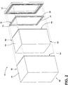
FIG. 2 is an exploded top perspective view of the insulating structure of the present disclosure. -
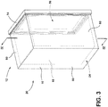
FIG. 3 is a top perspective view of the insulating structure of the present disclosure. -
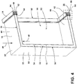
FIG. 4 is a cross-sectional view of the insulating structure ofFIG. 3 taken along line IV-IV of the present disclosure. -
FIG. 5 is a top perspective view of a trim breaker and a barrier structure of the present disclosure. -
FIG. 6 is a cross-sectional view of the insulating structure ofFIG. 4 taken at area VI of the present disclosure. -
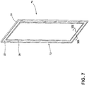
FIG. 7 is a top perspective view of the barrier structure of the present disclosure. -
FIG. 8 is a schematic cross-sectional view of an exemplary barrier structure taken along the line VIII-VIII of the present disclosure. -
FIG. 9 is a schematic cross-sectional view of an exemplary barrier structure of the present disclosure. -
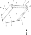
FIG. 10 is a schematic cross-sectional view of an exemplary barrier structure of the present disclosure. -
FIG. 11 is a schematic cross-sectional view of an exemplary barrier structure of the present disclosure. -
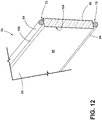
FIG. 12 is a schematic cross-sectional view of an exemplary barrier structure of the present disclosure. - The components in the figures are not necessarily to scale, emphasis instead being placed upon illustrating the principles described herein.
- The present illustrated embodiments reside primarily in apparatus components related to an insulating structure. Accordingly, the apparatus components have been represented, where appropriate, by conventional symbols in the drawings, showing only those specific details that are pertinent to understanding the embodiments of the present disclosure so as not to obscure the disclosure with details that will be readily apparent to those of ordinary skill in the art having the benefit of the description herein. Further, like numerals in the description and drawings represent like elements.
- For purposes of description herein, the terms "upper," "lower," "right," "left," "rear," "front," "vertical," "horizontal," and derivatives thereof shall relate to the disclosure as oriented in
FIG. 1 . Unless stated otherwise, the term "front" shall refer to the surface of the element closer to an intended viewer, and the term "rear" shall refer to the surface of the element further from the intended viewer. However, it is to be understood that the disclosure may assume various alternative orientations, except where expressly specified to the contrary. It is also to be understood that the specific devices and processes illustrated in the attached drawings, and described in the following specification are simply exemplary embodiments of the inventive concepts defined in the appended claims. Hence, specific dimensions and other physical characteristics relating to the embodiments disclosed herein are not to be considered as limiting, unless the claims expressly state otherwise. - The terms "including," "comprises," "comprising," or any other variation thereof, are intended to cover a non-exclusive inclusion, such that an article or apparatus that comprises a list of elements does not include only those elements but may include other elements not expressly listed or inherent to such article or apparatus. An element proceeded by "comprises a ..." does not, without more constraints, preclude the existence of additional identical elements in the article or apparatus that comprises the element.
- Referring to
FIGS. 1-12 ,reference numeral 10 generally designates an appliance having aninsulating structure 12. Theinsulating structure 12 may include atrim breaker 14, awrapper 16 coupled to thetrim breaker 14, and aliner 18 coupled to thetrim breaker 14. Theliner 18 and thewrapper 16 may at least partially define astructural cabinet 20. Theinsulating structure 12 typically includes abarrier 22 positioned within aninsulating cavity 24 between theliner 18 and thewrapper 16. Thebarrier 22 may also be coupled to thetrim breaker 14. An innercompressible gasket 26 is proximate theliner 18 and may be coupled to thebarrier 22. Additionally, an outercompressible gasket 28 is positioned proximate thewrapper 16 and also may be coupled to thebarrier 22. - Referring again to
FIGS. 1-12 , it is contemplated that theinsulating structure 12 may be in the form of a vacuum insulated structural cabinet or a vacuum insulated panel that may be used as an insulation member for theappliance 10. According to various examples, theinsulating structure 12 includes thewrapper 16 and theliner 18, which may alternatively be referred to as a first panel and a second panel, respectively. Thewrapper 16, theliner 18, and thebarrier 22, coupled to thetrim breaker 14, define theinsulating cavity 24 in which one ormore insulation materials 32 may be disposed. Theinsulation materials 32 may be a carbon-based powder and/or silicon oxide based materials; however, it is generally contemplated that otherstandard insulation materials 32 may be used as known in the art; such materials are described more fully below. The one ormore insulation materials 32 substantially fill theinsulating cavity 24 forming a substantially continuous layer between theliner 18 and thewrapper 16. An at leastpartial vacuum 34 is defined within theinsulating cavity 24, where the at leastpartial vacuum 34 defines a pressure differential 36 between anexterior 38 of theinsulating structure 12 and theinsulating cavity 24. This pressure differential 36 serves to define an inwardcompressive force 40 that is exerted upon both thewrapper 16 and theliner 18 and tends to bias thewrapper 16 and theliner 18 toward theinsulating cavity 24 of theinsulating structure 12. The at leastpartial vacuum 34 within theinsulating cavity 24 also tends to cause gas to infiltrate into theinsulating cavity 24 from an area exterior to theappliance 10. This infiltration of gas is sometimes referred to as gas permeation. - Referring again to
FIGS. 2-4 , as depicted in the form of thestructural cabinet 20, thewrapper 16 has a three-dimensional shape such that a plurality ofpanels 50 define acentral cavity 52. Correspondingly and as depicted, theliner 18 has a plurality ofsurfaces 54 defining aninner cavity 56. It is generally contemplated that theliner 18 may be received within thecentral cavity 52 of thewrapper 16, thus partially defining theinsulating cavity 24. Additionally, thewrapper 16 and theliner 18 includeinterior surfaces 58 andexterior surfaces 60 and may be made from a material capable of at least partially resisting bending, biasing, or otherwise being formed in response to the inwardcompressive force 40. These materials for theliner 18 and thewrapper 16 may include, but are not limited to, metals, plastics, polymers, metal alloys, combinations thereof, and other similar substantially rigid materials that can be used for vacuum insulated structures withinappliances 10. It is contemplated that theliner 18 and thewrapper 16 may also be used to form the vacuum insulated panel. In such constructions, thewrapper 16 may be referred to as the first panel, and theliner 18 may be referred to as the second panel, as stated above. - It is contemplated that an
inner groove 62, anouter groove 64, and acentral groove 66 are defined by thetrim breaker 14. The inner andouter grooves liner 18 and thewrapper 16, respectively, to define the insulatingstructure 12. Additionally, theouter groove 64 may be alternatively referred to as the first groove, and theinner groove 62 may alternatively be referred to as the second groove. The inner andouter grooves wrapper 16 and theliner 18 to thetrim breaker 14. Additionally, thecentral groove 66, defined by thetrim breaker 14, may be filled with the adhesive 68 configured to couple thebarrier 22 with thetrim breaker 14. As depicted inFIG. 6 , thecentral groove 66 may be shallower, as indicated by the dashed line, than the inner andouter grooves barrier 22 to thetrim breaker 14. - Alternatively, the adhesive 68 may be disposed directly on a receiving
surface 84 of thetrim breaker 14 between theliner 18 and thewrapper 16 such that thebarrier 22 may be coupled directly with thetrim breaker 14. Where the adhesive 68 is disposed directly on thetrim breaker 14, it is generally contemplated that thecentral groove 66 may not be needed for coupling thebarrier 22. Furthermore, the insulatingstructure 12 may be assembled by dispensing the adhesive 68 into the inner, outer, andcentral grooves liner 18 into theinner groove 62. Additionally, thebarrier 22, with the inner andouter gaskets central groove 66 while thewrapper 16 is positioned in theouter groove 64. The assembly as described may then be cured and additional adhesive 68 may be applied to the locations where thewrapper 16 and theliner 18 abut thetrim breaker 14. - A
gasket assembly 72 includes at least onegasket 74, which may be coupled to thebarrier 22, forming abarrier structure 76, to protect thebarrier 22 from interactions with theliner 18 and thewrapper 16. Additionally or alternatively, thebarrier 22 can include thegasket assembly 72. As illustrated inFIG. 4 , the innercompressible gasket 26, or inner gasket, is adjacent theliner 18 and the outercompressible gasket 28, or outer gasket, is adjacent thewrapper 16. When expressing gas from the insulatingcavity 24 theliner 18 and thewrapper 16 tend to bias towards one another such that the insulatingcavity 24 may be decreased. As a result of such biasing, theliner 18 and thewrapper 16 may exert the inwardcompressive force 40 upon thebarrier structure 76. Thegasket assembly 72 may protect thebarrier 22 from the inwardcompressive force 40 and from abrasive contact with theliner 18 and thewrapper 16. Specifically, when the inner andouter gaskets inner gasket 26 may protect thebarrier 22 from rough contact with theliner 18, and theouter gasket 28 may protect thebarrier 22 from rough contact with thewrapper 16. - Referring now to
FIGS. 4-6 , thetrim breaker 14 may be formed from a plastic material, but it will be understood by one having ordinary skill in the art that other materials may be used to form thetrim breaker 14. As depicted, thetrim breaker 14 has a generally rectangular shape; however, it is contemplated that other geometric shapes known in the art may be used. A plurality ofedges 78 form aborder 80 of the insulatingstructure 12 and define anopening 82. Said another way, theborder 80 of the insulatingstructure 12 is defined by the plurality ofedges 78 of thetrim breaker 14. The plurality ofedges 78 may further define theinner cavity 56 defined by theliner 18 by providing theborder 80 outlining theinner cavity 56. Additionally, the plurality ofedges 78 of thetrim breaker 14 may have a receivingsurface 84 and asolid surface 86, where the receivingsurface 84 may include the inner, central, andouter grooves liner 18, thebarrier 22, and thewrapper 16 may be received, respectively. - Moreover, the inner, outer, and
central grooves interior portions 88 that contact with and receive the adhesive 68 to secure theliner 18, thebarrier 22, and thewrapper 16. As indicated by the dashed line (shown inFIG. 6 ), thecentral groove 66 may have a shallower depth than the inner andouter grooves central groove 66. In certain embodiments, the adhesive 68 may overflow from thecentral groove 66. In such an embodiment, thebarrier 22 may be adhered at thecentral groove 66 and at the receivingsurface 84. Alternatively, thetrim breaker 14 may not include thecentral groove 66 such that thebarrier 22 may be coupled directly to the receivingsurface 84 of thetrim breaker 14. In a further alternative construction, thebarrier structure 76 may be disposed upon thetrim breaker 14 in such a way that there is no overlap of thebarrier structure 76 with the inner andouter grooves barrier structure 76 slightly overhangs the inner andouter grooves - Referring still to
FIGS. 5 and6 , thebarrier structure 76 is typically centrally disposed along thetrim breaker 14. Being centrally disposed theliner 18 and thewrapper 16 may surround thebarrier structure 76 such that thebarrier structure 76 is disposed between theliner 18 and thewrapper 16. As described above, thebarrier structure 76 includes thegasket assembly 72 that includes the inner andouter gaskets liner 18 and thewrapper 16 from directly contacting thebarrier 22. By way of example, and not limitation, theinner gasket 26 contacts theinterior portion 88 of theinner groove 62 and theinterior surface 58 of theliner 18; theouter gasket 28 contacts theinterior portion 88 of theouter groove 64 and theinterior surface 58 of thewrapper 16. - As illustrated in
FIGS. 6-8 , the inner andouter gaskets first lip 90 and asecond lip 92 connected by a bracingportion 94 such that the bracingportions 94 of the inner andouter gaskets interior surfaces 58 of theliner 18 and thewrapper 16. Thesecond lips 92 of the inner andouter gaskets interior portions 88 of the inner andouter grooves second lips 92 may further contact and couple with the adhesive 68 in the inner andouter grooves barrier 22 partially extends over the inner andouter grooves second lips 92 wrap around an adheringsurface 96 of thebarrier 22 to contact theinterior portions 88 of the inner andouter grooves first lips 90 wrap around aninsulation surface 98 of thebarrier 22 and thesecond lips 92 wrap around the adheringsurface 96 of thebarrier 22, such that thefirst lips 90, bracingportions 94, and thesecond lips 92 form a C-shape aroundedge portions 100 of thebarrier 22. - Referring again to
FIGS. 7 and8 , thebarrier structure 76 may be a generally rectangular shape to follow theborder 80 of the insulatingstructure 12. As such, thebarrier 22 may be one continuous piece of material. It is generally contemplated that thebarrier 22 may be constructed from glass, ceramic, or a glass-ceramic compound. Where one of these materials is used to form the barrier, it is contemplated that the gas permeation rates between thetrim breaker 14 and the insulatingcavity 24 are favorably diminished. For example, a glass barrier may have a lower gas permeation rate when compared with a plastic barrier. As such, the use of a glass barrier may maintain the at leastpartial vacuum 34 longer than a plastic barrier. The use of the glass barrier, in combination with themetallic liner 18 andwrapper 16 can further diminish the rate of gas permeation into the insulatingstructure 12. Thus, the integrity of the insulatingstructure 12, whether the vacuum insulated structural cabinet or panel, may be maintained, ultimately increasing the useful life of the insulatingstructure 12. - In further reference to
FIGS. 7 and8 , thebarrier 22 may be surrounded or partially surrounded by afilm 102, which may be asingle film 104 or include afirst film 106 and asecond film 108. Thefilm 102 may be a resin or laminate; however, it will be understood by one having ordinary skill in the art that other film materials may be used. Thefirst film 106 may be adhered to theinsulation surface 98 of thebarrier 22, and thesecond film 108 may be adhered to the adheringsurface 96 of thebarrier 22. Once installed, the insulatingstructure 12 may be subject to shifting, rough movement, and general wear-and-tear that accompanies the transport and use of theappliance 10. As such, there is potential for damage to thebarrier 22 throughout the useful life of thebarrier 22. Thefilm 102 may provide added protection by enveloping thebarrier 22. - By way of example, not limitation, where the
barrier 22 is made of glass it may fracture over time, such as during manufacture, delivery, or use of theappliance 10. If fracturing should occur, thefilm 102 helps to prevent glass from spreading throughout the insulatingstructure 12. Additionally, if fracturing were to occur, thefilm 102 may help maintain the at leastpartial vacuum 34 within the insulatingstructure 12 until the insulatingstructure 12 can be repaired. Thus, in combination with thegasket assembly 72 and thebarrier structure 76, thefilm 102 may extend the useful life of the insulatingstructure 12. - Additionally as illustrated, the
barrier 22 is surrounded by the inner andouter gaskets liner 18 andwrapper 16. Where glass is used to form thebarrier 22, the inner andouter gaskets barrier 22. Said another way, the inner andouter gaskets compressive force 40 is exerted upon the insulatingcavity 24, the inner andouter gaskets compressive force 40. Accordingly, the inner andouter gaskets compressive force 40 upon thebarrier 22. It is generally contemplated that the inner andouter gaskets inner gasket 26 may be one single piece and theouter gasket 28 may be one single piece; however, one having skill in the art would understand that other compressible materials may be used to form the inner andouter gaskets - Referring further to
FIGS. 9-12 , the at least onegasket 74 may extend across theinsulation surface 98 of the barrier such that thefirst lips 90 extend into acover portion 110 that extends between thefirst lips 90 and the inner andouter gaskets gasket 74 may extend partially along theedge portions 100 of thebarrier 22. Alternatively, the at least onegasket 74 may have thesecond lips 92 such that thecover portion 110, the bracingportion 94, and thesecond lips 92 may form a generally C-shape. It is also contemplated that thecover portion 110 may be intermittently disposed along thebarrier structure 76. Alternatively, thecover portion 110 may extend along thebarrier 22 such that theinsulation surface 98 of thebarrier 22 is covered by thecover portion 110. The at least onegasket 74 may provide buffer protection for thebarrier 22 with respect to thewrapper 16 and theliner 18. - Alternatively referring to
FIG. 10 , thegasket assembly 72 includes the inner andouter gaskets edge portions 100 of thebarrier 22. As illustrated inFIG. 10 , the inner andouter gaskets gasket assembly 72 includes only the bracingportions 94 that can include afirst extension 112 and asecond extension 114. Thefirst extension 112 may contact with theinsulation materials 32, and thesecond extension 114 may contact with the receivingsurface 84 of thetrim breaker 14. It is generally contemplated that the bracingportion 94 contacts with theinterior surfaces 58 of thewrapper 16 and theliner 18. Thebarrier structure 76 depicted inFIG. 10 may overhang the inner andouter grooves barrier 22 contacts the adhesive 68 in the inner andouter grooves barrier 22 is centrally aligned on thetrim breaker 14 such that overhang of thebarrier 22 relative the inner andouter grooves second extension 114 of thebarrier structure 76 contacts with both theinterior surfaces 58 of theliner 18 and thewrapper 16, respectively, as well as theinterior portions 88 of the inner andouter grooves - Referring to
FIGS. 11 and12 , thegasket assembly 72 includes the inner andouter gaskets outer gaskets portions 94 encompass the entirety of the inner andouter gaskets portions 94 contact the adhesive 68 in the inner andouter grooves interior surfaces 58 of theliner 18 and thewrapper 16, and theinsulation materials 32. As illustrated inFIG. 11 , thebarrier 22 includesrecesses 116 configured to receive and locate the inner andouter gaskets edge portions 100 of thebarrier 22. Alternatively, as illustrated inFIG. 12 , the inner andouter gaskets edge portions 100 of thebarrier 22 such that thebarrier 22 does not include therecesses 116. - According to the various examples, the insulating
structure 12 can be used invarious appliances 10 that can include, but are not limited to, refrigerators, freezers, coolers, ovens, dishwashers, laundry appliances, water heaters, and other similar appliances and fixtures within household and commercial settings. Additionally, theinsulation materials 32 can be a free-flowing material that can be poured, blown, compacted or otherwise disposed within the insulatingcavity 24. This free-flowing material can be in the form of various silica-based materials, such as fumed silica, precipitated silica, nano-sized and/or micro-sided aerogel powder, rice husk ash powder, perlite, glass spheres, hollow glass spheres, cenospheres, diatomaceous earth, combinations thereof, and other similar insulating particulate material. - According to another aspect of the present disclosure, an insulating structure for an appliance includes a trim breaker, a wrapper coupled to the trim breaker, a liner coupled to the trim breaker, wherein the liner and the wrapper at least partially define a structural cabinet, a barrier positioned between the liner and the wrapper, the barrier coupled to the trim breaker, an inner gasket proximate the liner and coupled to the barrier, and an outer gasket proximate the wrapper and coupled to the barrier.
- According to still another aspect of the present disclosure, the barrier is a material selected from the group consisting of glass, ceramic, and glass-ceramic.
- According to yet another aspect of the present disclosure, the trim breaker further defines an inner groove, a central groove, and an outer groove.
- According to another aspect of the present disclosure, the barrier is coupled to the trim breaker by adhesive disposed within the central groove.
- According to still another aspect of the present disclosure, insulation materials are disposed within a cavity defined by the liner and the wrapper.
- According to yet another aspect of the present disclosure, the wrapper is positioned within the outer groove and the liner is positioned within the inner groove.
- According to another aspect of the present disclosure, the barrier includes a first film and a second film.
- According to another aspect of the present disclosure, an insulating structure includes a trim breaker, a first panel coupled to the trim breaker, a second panel coupled to the trim breaker and proximate the first panel, and a barrier positioned between the first and the second panels.
- According to still another aspect of the present disclosure, the barrier is a material selected from the group consisting of glass, ceramic, and glass-ceramic compound.
- According to another aspect of the present disclosure, a first film and a second film, the first and second films coupled to the barrier.
- According to yet another aspect of the present disclosure, the trim breaker defines a first groove, a second groove, and a central groove.
- According to another aspect of the present disclosure, an adhesive is disposed within the central groove and couples the barrier with the trim breaker.
- According to another aspect of the present disclosure, the first panel is positioned within the first groove and the second panel is positioned within the second groove.
- According to still another aspect of the present disclosure, at least one gasket includes an inner gasket and an outer gasket, wherein the outer gasket is proximate the first panel and the inner gasket is proximate the second panel.
- According to another aspect of the present disclosure, wherein the at least one gasket is a compressible material.
- According to yet another aspect of the present disclosure, an appliance includes a trim breaker, a first panel coupled to the trim breaker, a second panel coupled to the trim breaker and proximate the first panel, a barrier of a glass-type material positioned between the first and the second panels, and the barrier coupled to the trim breaker.
- According to another aspect of the present disclosure, the first and second panels define a cavity.
- According to another aspect of the present disclosure, insulation materials disposed within the cavity defined by the first and second panels.
- According to still another aspect of the present disclosure, the barrier includes a gasket assembly.
- According to another aspect of the present disclosure, the barrier includes a film that is adhered to the barrier.
Claims (10)
- An insulating structure (12) comprising:a trim breaker (14);a first panel (16) coupled to the trim breaker (14);a second panel (18) coupled to the trim breaker (14) and arranged proximate the first panel (16);
wherein the first and second panels (16), (18) define an insulating cavity (24),
and wherein a barrier (22) is positioned within said insulating cavity (24) between the first panel (16) and the second panel (18), said barrier (22) being made of a material selected from the group consisting of glass, ceramic, and glass-ceramic compound. - The insulating structure (12) of claim 1, wherein the trim breaker (14) defines an inner groove (62) and an outer groove (64), said inner and outer grooves (62, 64) being configured to receive the second panel (18) and the first panel (16), respectively, to define the insulating structure (12).
- The insulating structure (12) of claim 2, wherein the trim breaker (14) further defines a central groove (66), said central groove (66) being configured to be filled with an adhesive (68) to couple the barrier (22) to the trim breaker (14).
- The insulating structure (12) of claim 3, wherein the trim breaker (14) includes a receiving surface (84) and a solid surface (86), and wherein the receiving surface (84) includes the inner, central, and outer grooves (62), (64), (66).
- The insulating structure (12) of any one of claims 1-4, wherein the barrier (22) is surrounded or partially surrounded by a film (102), said film (102) being a single film (104) or including a first film (106) and a second film (108).
- The insulating structure (12) of any one or more of claims 1-5, further comprising at least one gasket (74) includes an inner gasket (26) and an outer gasket (28), wherein the outer gasket (28) is proximate the first panel (16) and the inner gasket (26) is proximate the second panel (18).
- The insulating structure (12) of claim 6, wherein the at least one gasket (74) is made of a compressible material.
- The insulating structure (12) of any one of claims 1-7, including insulation materials (32) disposed within the cavity (24) defined by the first and second panels (16), (18).
- A refrigerating appliance including the insulating structure (12) of any one of claims 1-8.
- A freezer appliance including the insulating structure (12) of any one of claims 1-8.
Applications Claiming Priority (1)
| Application Number | Priority Date | Filing Date | Title |
|---|---|---|---|
| US16/399,269 US11320194B2 (en) | 2019-04-30 | 2019-04-30 | Barrier layer for insulated structures |
Publications (1)
| Publication Number | Publication Date |
|---|---|
| EP3734202A1 true EP3734202A1 (en) | 2020-11-04 |
Family
ID=70189791
Family Applications (1)
| Application Number | Title | Priority Date | Filing Date |
|---|---|---|---|
| EP20168107.9A Withdrawn EP3734202A1 (en) | 2019-04-30 | 2020-04-03 | Barrier layer for insulated structures |
Country Status (3)
| Country | Link |
|---|---|
| US (4) | US11320194B2 (en) |
| EP (1) | EP3734202A1 (en) |
| CN (1) | CN111853429A (en) |
Cited By (1)
| Publication number | Priority date | Publication date | Assignee | Title |
|---|---|---|---|---|
| EP3805675A1 (en) * | 2019-10-11 | 2021-04-14 | Whirlpool Corporation | Vacuum insulated structure |
Families Citing this family (2)
| Publication number | Priority date | Publication date | Assignee | Title |
|---|---|---|---|---|
| US11320194B2 (en) * | 2019-04-30 | 2022-05-03 | Whirlpool Corporation | Barrier layer for insulated structures |
| US20240247864A1 (en) * | 2023-01-24 | 2024-07-25 | Whirlpool Corporation | Cabinet for a refrigeration unit |
Citations (6)
| Publication number | Priority date | Publication date | Assignee | Title |
|---|---|---|---|---|
| DE102015222224A1 (en) * | 2015-11-11 | 2017-05-11 | BSH Hausgeräte GmbH | Door for a household refrigerator with a cover of a display device forming door closure strip and household refrigeration appliance with such a door |
| WO2017100037A1 (en) * | 2015-12-09 | 2017-06-15 | Whirlpool Corporation | Vacuum insulation structures with multiple insulators |
| WO2018044274A1 (en) * | 2016-08-30 | 2018-03-08 | Whirlpool Corporation | Hermetically sealed overmolded plastic thermal bridge breaker with liner and wrapper for a vacuum insulated structure |
| WO2019108204A1 (en) * | 2017-11-30 | 2019-06-06 | Whirlpool Corporation | Vacuum insulated structure with thermal bridge breaker with heat loop |
| EP3647696A1 (en) * | 2018-10-31 | 2020-05-06 | Whirlpool Corporation | Polymer trim breaker having gas-blocking flakes and an epoxy coating |
| EP3696483A1 (en) * | 2019-02-18 | 2020-08-19 | Whirlpool Corporation | Trim breaker for a structural cabinet that incorporates a structural glass contact surface |
Family Cites Families (43)
| Publication number | Priority date | Publication date | Assignee | Title |
|---|---|---|---|---|
| US2518673A (en) * | 1945-05-14 | 1950-08-15 | Seeger Refrigerator Co | Breaker strip construction |
| US2644606A (en) * | 1950-02-28 | 1953-07-07 | Int Harvester Co | Breaker strip construction |
| US2644605A (en) * | 1950-02-28 | 1953-07-07 | Int Harvester Co | Breaker strip construction |
| US2792959A (en) * | 1953-09-28 | 1957-05-21 | Whirlpool Seeger Corp | Plastic breaker strip construction |
| US2809764A (en) * | 1955-12-27 | 1957-10-15 | Whirlpool Seeger Corp | Duo-plastic molded breaker strip |
| US2855636A (en) * | 1957-02-18 | 1958-10-14 | Ben Hur Mfg Company | Edge dovetail insulated wall construction |
| GB837929A (en) | 1958-03-07 | 1960-06-15 | Whirlpool Co | Heat insulating panels |
| CA1290625C (en) * | 1985-11-07 | 1991-10-15 | Gunter Berdan | Spacer assembly for multiple glazed unit |
| US4831780A (en) * | 1987-07-07 | 1989-05-23 | Ardco Inc. | Refrigerator door assembly with thermal break frame |
| US4891912A (en) * | 1987-07-07 | 1990-01-09 | Ardco, Inc. | Refrigerator door assembly with multiple gasket sealing arrangement |
| US5088258A (en) * | 1990-09-07 | 1992-02-18 | Weather Shield Mfg., Inc. | Thermal broken glass spacer |
| US5910083A (en) * | 1990-09-20 | 1999-06-08 | New Anthony, Inc. | Integral spacer for door rail |
| CA2131918A1 (en) * | 1992-05-18 | 1993-11-25 | Charles D. Newby | Metal-polymer composite insulative spacer for glass members and insulative window containing same |
| US5487937A (en) * | 1992-05-18 | 1996-01-30 | Crane Plastics Company Limited Partnership | Metal-polymer composite insulative spacer for glass members and insulative window containing same |
| US6637093B2 (en) * | 1998-03-03 | 2003-10-28 | Anthony, Inc. | Method of assembling a display case door |
| DE19907182A1 (en) * | 1999-02-19 | 2000-08-24 | Bsh Bosch Siemens Hausgeraete | Heat-insulating wall, like refrigerator door, refrigerator housing or similar has supported in front of membrane cover, protection profile fixed on inner and/or outer cladding, overlapping this as far as possible. |
| US6148563A (en) * | 1999-03-25 | 2000-11-21 | Hussmann Corporation | Reach-in door for refrigerated merchandiser |
| US6094290A (en) * | 1999-04-22 | 2000-07-25 | Crawford; Christopher L. | Light-reactive thermal window |
| JP2005036975A (en) * | 2003-06-27 | 2005-02-10 | Matsushita Electric Ind Co Ltd | Insulating material, manufacturing method thereof, and equipment using the insulating material |
| JP3764744B2 (en) * | 2004-02-06 | 2006-04-12 | 横浜ゴム株式会社 | Thermoplastic resin composition and multilayer glass using the same |
| DE102007034298A1 (en) | 2007-07-24 | 2009-01-29 | BSH Bosch und Siemens Hausgeräte GmbH | Refrigeration unit with vacuum insulation |
| US8402716B2 (en) * | 2008-05-21 | 2013-03-26 | Serious Energy, Inc. | Encapsulated composit fibrous aerogel spacer assembly |
| US20100146883A1 (en) * | 2008-12-17 | 2010-06-17 | Benkel Friedrich K | Muntin bar clip for foam spacer |
| US10125535B2 (en) * | 2009-04-07 | 2018-11-13 | Lisec Austria Gmbh | Spacer for spacing glass panes in a multiple glass pane, a multiple glass pane, and a method for producing a multiple glass pane |
| EP2622292B1 (en) | 2010-10-01 | 2020-05-13 | LG Electronics Inc. | Vacuum insulation panel and a refrigerator with a vacuum insulation panel |
| KR101227516B1 (en) * | 2010-10-28 | 2013-01-31 | 엘지전자 주식회사 | A refrigerator comprising a vacuum space |
| CN102116402A (en) * | 2011-01-04 | 2011-07-06 | 合肥美的荣事达电冰箱有限公司 | Vacuum thermal insulation component and manufacturing method thereof, as well as refrigeration device |
| EP2719533A1 (en) * | 2012-10-12 | 2014-04-16 | Amcor Flexibles Kreuzlingen Ltd. | Insulating glazing unit |
| SG10201801356QA (en) | 2013-06-07 | 2018-03-28 | Mitsubishi Electric Corp | Heat insulating box body and refrigerator |
| US10088092B2 (en) * | 2013-07-05 | 2018-10-02 | Amogreentech Co., Ltd. | Thermal insulation sheet, hybrid thermal insulation sheet, and thermal insulation panel |
| CN203614994U (en) * | 2013-08-20 | 2014-05-28 | 糜玥崎 | Decorative insulation plate and refrigeration equipment applying same |
| CN106715819B (en) * | 2014-09-25 | 2019-08-13 | 法国圣戈班玻璃厂 | Spacers for insulating glazing |
| US20160258671A1 (en) * | 2015-03-02 | 2016-09-08 | Whirlpool Corporation | Gas barrier for vacuum insulation |
| US20170159996A1 (en) | 2015-12-08 | 2017-06-08 | Whirlpool Corporation | Vacuum insulation structures with a filler insulator |
| US10907890B2 (en) * | 2016-04-14 | 2021-02-02 | Whirlpool Corporation | Double cabinet vacuum insulated refrigerator with a structural foamed mullion |
| WO2018022009A1 (en) * | 2016-07-26 | 2018-02-01 | Whirlpool Corporation | Thermal bridgebreaker and seal features in a thin-walled vacuum insulated structure |
| CN108613462A (en) | 2016-12-12 | 2018-10-02 | 博西华电器(江苏)有限公司 | Refrigerating appliance and its insulated door |
| CN108224887B (en) | 2016-12-12 | 2021-07-06 | 博西华电器(江苏)有限公司 | Refrigeration appliance and its thermal insulation door |
| CN108613465B (en) | 2016-12-12 | 2022-02-11 | 博西华电器(江苏)有限公司 | Refrigeration appliance and heat insulation door thereof |
| CN108613464B (en) | 2016-12-12 | 2022-08-12 | 博西华电器(江苏)有限公司 | Refrigeration appliance and its thermal insulation door |
| CN206709470U (en) | 2017-03-09 | 2017-12-05 | 博西华电器(江苏)有限公司 | refrigerator |
| US10697699B2 (en) * | 2018-11-05 | 2020-06-30 | Whirlpool Corporation | Cabinet assembly of an appliance |
| US11320194B2 (en) | 2019-04-30 | 2022-05-03 | Whirlpool Corporation | Barrier layer for insulated structures |
-
2019
- 2019-04-30 US US16/399,269 patent/US11320194B2/en active Active
-
2020
- 2020-04-03 EP EP20168107.9A patent/EP3734202A1/en not_active Withdrawn
- 2020-04-29 CN CN202010357647.5A patent/CN111853429A/en active Pending
-
2022
- 2022-03-25 US US17/704,143 patent/US11686525B2/en active Active
-
2023
- 2023-04-27 US US18/308,091 patent/US12031771B2/en active Active
-
2024
- 2024-06-18 US US18/746,541 patent/US20240337432A1/en not_active Abandoned
Patent Citations (6)
| Publication number | Priority date | Publication date | Assignee | Title |
|---|---|---|---|---|
| DE102015222224A1 (en) * | 2015-11-11 | 2017-05-11 | BSH Hausgeräte GmbH | Door for a household refrigerator with a cover of a display device forming door closure strip and household refrigeration appliance with such a door |
| WO2017100037A1 (en) * | 2015-12-09 | 2017-06-15 | Whirlpool Corporation | Vacuum insulation structures with multiple insulators |
| WO2018044274A1 (en) * | 2016-08-30 | 2018-03-08 | Whirlpool Corporation | Hermetically sealed overmolded plastic thermal bridge breaker with liner and wrapper for a vacuum insulated structure |
| WO2019108204A1 (en) * | 2017-11-30 | 2019-06-06 | Whirlpool Corporation | Vacuum insulated structure with thermal bridge breaker with heat loop |
| EP3647696A1 (en) * | 2018-10-31 | 2020-05-06 | Whirlpool Corporation | Polymer trim breaker having gas-blocking flakes and an epoxy coating |
| EP3696483A1 (en) * | 2019-02-18 | 2020-08-19 | Whirlpool Corporation | Trim breaker for a structural cabinet that incorporates a structural glass contact surface |
Cited By (4)
| Publication number | Priority date | Publication date | Assignee | Title |
|---|---|---|---|---|
| EP3805675A1 (en) * | 2019-10-11 | 2021-04-14 | Whirlpool Corporation | Vacuum insulated structure |
| US11287177B2 (en) | 2019-10-11 | 2022-03-29 | Whirlpool Corporation | Vacuum insulated structure |
| US11644232B2 (en) | 2019-10-11 | 2023-05-09 | Whirlpool Corporation | Vacuum insulated structure |
| US11940205B2 (en) | 2019-10-11 | 2024-03-26 | Whirlpool Corporation | Vacuum insulated structure |
Also Published As
| Publication number | Publication date |
|---|---|
| US11686525B2 (en) | 2023-06-27 |
| US20200348074A1 (en) | 2020-11-05 |
| US20240337432A1 (en) | 2024-10-10 |
| US12031771B2 (en) | 2024-07-09 |
| US11320194B2 (en) | 2022-05-03 |
| US20230266053A1 (en) | 2023-08-24 |
| CN111853429A (en) | 2020-10-30 |
| US20220214099A1 (en) | 2022-07-07 |
Similar Documents
| Publication | Publication Date | Title |
|---|---|---|
| US11940205B2 (en) | Vacuum insulated structure | |
| US12031771B2 (en) | Barrier layer for insulated structures | |
| EP3827957B1 (en) | Refrigerator | |
| EP3519746B1 (en) | Encapsulation system for a thermal bridge breaker-to-metal liner | |
| EP3443283B1 (en) | Double cabinet vacuum insulated refrigerator with a structural foamed mullion | |
| EP3615872B1 (en) | Structural cabinet for an appliance | |
| EP3839385B1 (en) | Insulated door assembly | |
| EP3792575B1 (en) | Standoff assembly for a household appliance | |
| EP3696483B1 (en) | Trim breaker for a structural cabinet that incorporates a structural glass contact surface | |
| KR101645974B1 (en) | Composite heat-insulating material having vacuum insulation panel and its manufacturing method | |
| CN207487227U (en) | refrigeration refrigerator | |
| CN107388710A (en) | refrigerator door and refrigerator | |
| CN207180149U (en) | refrigerator door and refrigerator | |
| KR20120061092A (en) | Vacuum insulation glass panel and refrigerator having the same |
Legal Events
| Date | Code | Title | Description |
|---|---|---|---|
| PUAI | Public reference made under article 153(3) epc to a published international application that has entered the european phase |
Free format text: ORIGINAL CODE: 0009012 |
|
| STAA | Information on the status of an ep patent application or granted ep patent |
Free format text: STATUS: THE APPLICATION HAS BEEN PUBLISHED |
|
| AK | Designated contracting states |
Kind code of ref document: A1 Designated state(s): AL AT BE BG CH CY CZ DE DK EE ES FI FR GB GR HR HU IE IS IT LI LT LU LV MC MK MT NL NO PL PT RO RS SE SI SK SM TR |
|
| AX | Request for extension of the european patent |
Extension state: BA ME |
|
| STAA | Information on the status of an ep patent application or granted ep patent |
Free format text: STATUS: REQUEST FOR EXAMINATION WAS MADE |
|
| 17P | Request for examination filed |
Effective date: 20210504 |
|
| RBV | Designated contracting states (corrected) |
Designated state(s): AL AT BE BG CH CY CZ DE DK EE ES FI FR GB GR HR HU IE IS IT LI LT LU LV MC MK MT NL NO PL PT RO RS SE SI SK SM TR |
|
| STAA | Information on the status of an ep patent application or granted ep patent |
Free format text: STATUS: EXAMINATION IS IN PROGRESS |
|
| 17Q | First examination report despatched |
Effective date: 20230103 |
|
| P01 | Opt-out of the competence of the unified patent court (upc) registered |
Effective date: 20230821 |
|
| GRAP | Despatch of communication of intention to grant a patent |
Free format text: ORIGINAL CODE: EPIDOSNIGR1 |
|
| STAA | Information on the status of an ep patent application or granted ep patent |
Free format text: STATUS: GRANT OF PATENT IS INTENDED |
|
| INTG | Intention to grant announced |
Effective date: 20241011 |
|
| STAA | Information on the status of an ep patent application or granted ep patent |
Free format text: STATUS: THE APPLICATION IS DEEMED TO BE WITHDRAWN |
|
| 18D | Application deemed to be withdrawn |
Effective date: 20250212 |