EP3734076A1 - Oil supplying mechanism, and horizontal compressor having same - Google Patents
Oil supplying mechanism, and horizontal compressor having same Download PDFInfo
- Publication number
- EP3734076A1 EP3734076A1 EP18893372.5A EP18893372A EP3734076A1 EP 3734076 A1 EP3734076 A1 EP 3734076A1 EP 18893372 A EP18893372 A EP 18893372A EP 3734076 A1 EP3734076 A1 EP 3734076A1
- Authority
- EP
- European Patent Office
- Prior art keywords
- partition member
- oil
- bearing seat
- pump
- supply mechanism
- Prior art date
- Legal status (The legal status is an assumption and is not a legal conclusion. Google has not performed a legal analysis and makes no representation as to the accuracy of the status listed.)
- Granted
Links
- 230000007246 mechanism Effects 0.000 title claims abstract description 84
- 239000003921 oil Substances 0.000 claims description 198
- 238000005192 partition Methods 0.000 claims description 133
- 238000007789 sealing Methods 0.000 claims description 28
- 230000002093 peripheral effect Effects 0.000 claims description 21
- 239000010687 lubricating oil Substances 0.000 claims description 17
- 238000000034 method Methods 0.000 claims description 8
- 230000008569 process Effects 0.000 claims description 8
- 238000007689 inspection Methods 0.000 abstract description 6
- NJPPVKZQTLUDBO-UHFFFAOYSA-N novaluron Chemical compound C1=C(Cl)C(OC(F)(F)C(OC(F)(F)F)F)=CC=C1NC(=O)NC(=O)C1=C(F)C=CC=C1F NJPPVKZQTLUDBO-UHFFFAOYSA-N 0.000 abstract 3
- 230000004323 axial length Effects 0.000 description 4
- 230000006835 compression Effects 0.000 description 4
- 238000007906 compression Methods 0.000 description 4
- 238000011990 functional testing Methods 0.000 description 4
- 230000000694 effects Effects 0.000 description 2
- 230000002411 adverse Effects 0.000 description 1
- 238000005219 brazing Methods 0.000 description 1
- 238000013461 design Methods 0.000 description 1
- 239000012530 fluid Substances 0.000 description 1
- 230000006872 improvement Effects 0.000 description 1
- 238000010348 incorporation Methods 0.000 description 1
- 238000012986 modification Methods 0.000 description 1
- 230000004048 modification Effects 0.000 description 1
- 238000004321 preservation Methods 0.000 description 1
- 239000003507 refrigerant Substances 0.000 description 1
Images


Classifications
-
- F—MECHANICAL ENGINEERING; LIGHTING; HEATING; WEAPONS; BLASTING
- F04—POSITIVE - DISPLACEMENT MACHINES FOR LIQUIDS; PUMPS FOR LIQUIDS OR ELASTIC FLUIDS
- F04C—ROTARY-PISTON, OR OSCILLATING-PISTON, POSITIVE-DISPLACEMENT MACHINES FOR LIQUIDS; ROTARY-PISTON, OR OSCILLATING-PISTON, POSITIVE-DISPLACEMENT PUMPS
- F04C29/00—Component parts, details or accessories of pumps or pumping installations, not provided for in groups F04C18/00 - F04C28/00
- F04C29/02—Lubrication; Lubricant separation
- F04C29/028—Means for improving or restricting lubricant flow
-
- F—MECHANICAL ENGINEERING; LIGHTING; HEATING; WEAPONS; BLASTING
- F04—POSITIVE - DISPLACEMENT MACHINES FOR LIQUIDS; PUMPS FOR LIQUIDS OR ELASTIC FLUIDS
- F04C—ROTARY-PISTON, OR OSCILLATING-PISTON, POSITIVE-DISPLACEMENT MACHINES FOR LIQUIDS; ROTARY-PISTON, OR OSCILLATING-PISTON, POSITIVE-DISPLACEMENT PUMPS
- F04C23/00—Combinations of two or more pumps, each being of rotary-piston or oscillating-piston type, specially adapted for elastic fluids; Pumping installations specially adapted for elastic fluids; Multi-stage pumps specially adapted for elastic fluids
- F04C23/008—Hermetic pumps
-
- F—MECHANICAL ENGINEERING; LIGHTING; HEATING; WEAPONS; BLASTING
- F04—POSITIVE - DISPLACEMENT MACHINES FOR LIQUIDS; PUMPS FOR LIQUIDS OR ELASTIC FLUIDS
- F04C—ROTARY-PISTON, OR OSCILLATING-PISTON, POSITIVE-DISPLACEMENT MACHINES FOR LIQUIDS; ROTARY-PISTON, OR OSCILLATING-PISTON, POSITIVE-DISPLACEMENT PUMPS
- F04C29/00—Component parts, details or accessories of pumps or pumping installations, not provided for in groups F04C18/00 - F04C28/00
- F04C29/02—Lubrication; Lubricant separation
- F04C29/025—Lubrication; Lubricant separation using a lubricant pump
-
- F—MECHANICAL ENGINEERING; LIGHTING; HEATING; WEAPONS; BLASTING
- F04—POSITIVE - DISPLACEMENT MACHINES FOR LIQUIDS; PUMPS FOR LIQUIDS OR ELASTIC FLUIDS
- F04C—ROTARY-PISTON, OR OSCILLATING-PISTON, POSITIVE-DISPLACEMENT MACHINES FOR LIQUIDS; ROTARY-PISTON, OR OSCILLATING-PISTON, POSITIVE-DISPLACEMENT PUMPS
- F04C2240/00—Components
- F04C2240/30—Casings or housings
-
- F—MECHANICAL ENGINEERING; LIGHTING; HEATING; WEAPONS; BLASTING
- F04—POSITIVE - DISPLACEMENT MACHINES FOR LIQUIDS; PUMPS FOR LIQUIDS OR ELASTIC FLUIDS
- F04C—ROTARY-PISTON, OR OSCILLATING-PISTON, POSITIVE-DISPLACEMENT MACHINES FOR LIQUIDS; ROTARY-PISTON, OR OSCILLATING-PISTON, POSITIVE-DISPLACEMENT PUMPS
- F04C2240/00—Components
- F04C2240/50—Bearings
- F04C2240/56—Bearing bushings or details thereof
-
- F—MECHANICAL ENGINEERING; LIGHTING; HEATING; WEAPONS; BLASTING
- F04—POSITIVE - DISPLACEMENT MACHINES FOR LIQUIDS; PUMPS FOR LIQUIDS OR ELASTIC FLUIDS
- F04C—ROTARY-PISTON, OR OSCILLATING-PISTON, POSITIVE-DISPLACEMENT MACHINES FOR LIQUIDS; ROTARY-PISTON, OR OSCILLATING-PISTON, POSITIVE-DISPLACEMENT PUMPS
- F04C2240/00—Components
- F04C2240/80—Other components
- F04C2240/806—Pipes for fluids; Fittings therefor
-
- F—MECHANICAL ENGINEERING; LIGHTING; HEATING; WEAPONS; BLASTING
- F04—POSITIVE - DISPLACEMENT MACHINES FOR LIQUIDS; PUMPS FOR LIQUIDS OR ELASTIC FLUIDS
- F04C—ROTARY-PISTON, OR OSCILLATING-PISTON, POSITIVE-DISPLACEMENT MACHINES FOR LIQUIDS; ROTARY-PISTON, OR OSCILLATING-PISTON, POSITIVE-DISPLACEMENT PUMPS
- F04C2240/00—Components
- F04C2240/80—Other components
- F04C2240/809—Lubricant sump
-
- F—MECHANICAL ENGINEERING; LIGHTING; HEATING; WEAPONS; BLASTING
- F04—POSITIVE - DISPLACEMENT MACHINES FOR LIQUIDS; PUMPS FOR LIQUIDS OR ELASTIC FLUIDS
- F04C—ROTARY-PISTON, OR OSCILLATING-PISTON, POSITIVE-DISPLACEMENT MACHINES FOR LIQUIDS; ROTARY-PISTON, OR OSCILLATING-PISTON, POSITIVE-DISPLACEMENT PUMPS
- F04C29/00—Component parts, details or accessories of pumps or pumping installations, not provided for in groups F04C18/00 - F04C28/00
- F04C29/02—Lubrication; Lubricant separation
- F04C29/026—Lubricant separation
Definitions
- the present disclosure relates to the field of compressor, and in particular to a horizontal scroll compressor having an improvement on its oil supply mechanism.
- a compressor generally includes a housing, a compression mechanism housed in the housing, a motor that provides power to the compression mechanism, a rotating shaft driven by the motor, and an oil supply mechanism that supplies lubricating oil to various moving parts of the compressor.
- an oil sump is generally provided at the bottom of the compressor housing and an oil pump is provided at the bottom end of the rotating shaft to pump the lubricating oil preserved in the oil sump to an oilhole axially extending in the rotating shaft, thereby supplying lubricating oil to the various moving parts of the compressor.
- a horizontal compressor is required. Since the horizontal compressor cannot naturally form an oil sump at a tail end of the rotating shaft, some oil supply mechanisms for the horizontal compressor are provided to realize the preservation and delivery of lubricating oil.
- a partition plate may be provided to separate out two compartments with a pressure difference (a discharge pressure difference) in the high-pressure region to form in the lower pressure compartment an oil sump which can rise by means of the pressure difference, so that the high-pressure lubricating oil can be delivered to the oil pump (a single oil pump) at the tail end of the rotating shaft.
- the high-temperature and high-pressure lubricating oil in the high-pressure region can be introduced into the oil pump at the tail end of the rotating shaft, and a double-layer housing can be used to form an oil sump in the low-pressure region, or a vertical and straight partition member can be used to separate out an individual oil sump in the low-pressure region.
- An object of the present disclosure is to provide an oil supply mechanism capable of reducing or minimizing free space in a motor chamber.
- Another object of the present disclosure is to provide an oil supply mechanism capable of reducing the overall size of a horizontal compressor when the size of an oil storage chamber is fixed.
- Another object of the present disclosure is to provide an oil supply mechanism capable of reducing or minimizing the free space in the motor chamber while allowing a stable engagement of a partition member and a housing.
- Another object of the present disclosure is to provide an oil supply mechanism capable of achieving reliable and stable connection and sealing of a partition member and a bearing seat.
- Another object of the present disclosure is to provide an oil supply mechanism capable of achieving reducing or minimizing the free space in the motor chamber while appropriately avoiding interference with related components around the bearing seat.
- Another object of the present disclosure is to provide an oil supply mechanism through which a functional test can be conveniently performed on a pump structure.
- Another object of the present disclosure is to provide an oil supply mechanism capable of avoiding improperly increasing an axial length of a pump-bearing seat assembly.
- Another object of the present disclosure is to provide a horizontal compressor associated with the above oil supply mechanism.
- an oil supply mechanism for a horizontal compressor includes a housing, a motor, a rotating shaft driven by the motor, and a bearing seat supporting the rotating shaft.
- the oil supply mechanism includes a partition member.
- the partition member is ring-shaped and has a central hole allowing the bearing seat to pass through, and the partition member is configured to separate out in the housing an oil storage chamber and a motor chamber in which the motor is provided.
- the partition member is configured to have an annular groove opened toward the oil storage chamber.
- a radially outer portion of the partition member is connected to an inner peripheral surface of the housing and a radially inner portion of the partition member is connected to an outer peripheral surface of the bearing seat.
- the housing includes a housing body and an end cover, and the radially outer portion of the partition member is connected to both the housing body and the end cover.
- the partition member includes a partition member body, an inner flange portion serving as a radially inner portion of the partition member that extends away from the oil storage chamber, an outer flange portion serving as a radially outer portion of the partition member that extends toward the oil storage chamber, and a bent portion located between the partition member body and the inner flange portion and protruding toward the oil storage chamber.
- the partition member body, the outer flange portion, and the bent portion together define the annular groove.
- the partition member includes a partition member body, an inner flange portion serving as a radially inner portion of the partition member, and an outer flange portion serving as a radially outer portion of the partition member, wherein the inner flange portion and the outer flange portion extend toward the oil storage chamber, and, the partition member body, the inner flange portion, and the outer flange portion thereby together define the annular groove.
- the oil supply mechanism further includes an annular sealing member provided between the radially inner portion of the partition member and the outer peripheral surface of the bearing seat.
- a sealing member groove is provided on the inner peripheral surface of the radially inner portion of the partition member and/or on the outer peripheral surface of the bearing seat, and the annular sealing member is accommodated in the sealing member groove.
- a ridge is provided on the outer peripheral surface of the radially outer portion of the partition member, and the ridge is interposed between the housing body and the end cover of the housing.
- the partition member is an integral part formed by a deep drawing process.
- the partition member is such configured that the partition member body of the partition member defining the annular groove is offset toward the motor chamber and is closer to one end of the motor.
- the oil supply mechanism further includes a pump device attached to the bearing seat at one end of the rotating shaft, so that the pump device and the bearing seat constitute a pump-bearing seat assembly.
- the pump device includes a first pump configured to deliver the lubricating oil in the motor chamber to the oil storage chamber, and an oil discharge pipe for the first pump.
- a first port of the oil discharge pipe is connected to the pump-bearing seat assembly, and a second port of the oil discharge pipe enters the oil storage chamber through an opening provided at the partition member.
- the oil supply mechanism further includes a pump device attached to the bearing seat at one end of the rotating shaft, so that the pump device and the bearing seat constitute a pump-bearing seat assembly.
- the pump device includes a first pump configured to deliver the lubricating oil in the motor chamber to the oil storage chamber, a second pump configured to deliver the lubricating oil in the oil storage chamber to the oilhole in the rotating shaft, a first oil inlet-pipe for the first pump and a second oil inlet-pipe for the second pump extending substantially vertically downward from the pump-bearing seat assembly on the motor chamber side and on the oil storage chamber side respectively.
- the first oil inlet-pipe and/or the second oil inlet-pipe are detachably connected to the pump-bearing seat assembly.
- the first oil inlet-pipe and/or the second oil inlet-pipe have a threaded structure, and thereby can be screwed to the pump-bearing seat assembly, or, the first oil inlet-pipe and/or the second oil inlet-pipe are fixed to the pump-bearing seat assembly by threaded fasteners and positioning pins.
- the horizontal compressor further includes a bearing seat bracket for fixing the bearing seat and the partition member is a component different from the bearing seat bracket.
- an oil supply mechanism for a horizontal compressor includes a housing, a motor, a rotating shaft driven by the motor, and a bearing seat supporting the rotating shaft.
- the oil supply mechanism includes a partition member and a pump device.
- the partition member is configured to separate out in the housing an oil storage chamber and a motor chamber in which the motor is provided, and the pump device is attached to the bearing seat at one end of the rotating shaft, so that the pump device and the bearing seat constitute a pump-bearing seat assembly.
- the pump device includes a first pump configured to deliver the lubricating oil in the motor chamber to the oil storage chamber and an oil discharge pipe for the first pump.
- a first port of the oil discharge pipe is connected to the pump-bearing seat assembly on the motor chamber side, and a second port of the oil discharge pipe enters the oil storage chamber from the motor chamber side through an opening provided at the partition member.
- a horizontal compressor has an oil supply mechanism as described above.
- the horizontal compressor is a low-pressure side scroll compressor.
- the partition member defines the annular groove having a larger depth opening toward the oil storage chamber by, for example, a deep drawing process, it is possible to reduce or minimize the free space (useless free space) in the motor chamber, and thereby the overall size (especially the axial size) of the horizontal compressor can be reduced when the size of the oil storage chamber is fixed.
- the partition member having the annular groove and the outer flange portion extending toward the oil storage chamber it is possible to reduce or minimize the free space in the motor chamber while allowing the partition member to be respectively connected with the housing body and the end cover so as to realize a stable engagement of the partition member, the housing body and the end cover.
- partition member having the inner flange portion it is possible to realize reliable and stable connection and sealing of the partition member and the bearing seat.
- the partition member having the bent portion protruding toward the oil storage chamber it is possible to reduce or minimize the free space in the motor chamber while appropriately avoiding interference with related components around the bearing seat.
- the functional test quality inspection
- the structure is simplified and improper increase in the axial length of the pump-bearing seat assembly (especially the bearing seat) due to the provision of the oil discharge passage inside the pump-bearing seat assembly is avoided.
- the horizontal compressor 10 is a low-pressure side scroll compressor.
- the oil supply mechanism 100 according to the present disclosure may be applied to other horizontal compressors.
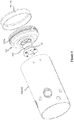
- the horizontal compressor 10 includes a housing 20, a motor 30, a rotating shaft 40 driven by the motor 30, and a bearing seat 50 supporting the rotating shaft 40.
- the housing 20 includes a housing body 20a, and a first end cover 20b and a second end cover 20c which are respectively provided at two ends of the housing body 20a.
- the horizontal compressor 10 further includes a compression mechanism 60 and a partition plate (muffler plate) 70.
- the compression mechanism 60 is driven by the rotating shaft 40 to compress the working fluid (for example, refrigerant).
- the partition plate 70 separates the internal space defined by the housing 20 (specifically, by the housing body 20a, the first end cover 20b, and the second end cover 20c) into a high-pressure region (located on the left side of the partition plate 70 as shown in Figure 1 ) and a low-pressure region (located on the right side of the partition plate 70 as shown in Figure 1 ).
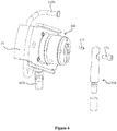
- the oil supply mechanism 100 includes a partition member 120.
- the partition member 120 is in a ring shape (for example, in a substantially circular ring shape) and has a central hole 129 allowing the bearing seat 50 to pass through.
- the partition member 120 is configured to separate out in the housing 20 an oil storage chamber OC and a motor chamber MC in which the motor 30 is provided.
- the oil storage chamber OC located on one side with respect to an axial direction and the motor chamber MC located on the other side with respect to the axial direction are both located in the low-pressure region.
- a radially outer portion of the partition member 120 is connected to an inner peripheral surface 22 of the housing 20 and a radially inner portion of the partition member 120 is connected to an outer peripheral surface 52 of the bearing seat 50.
- the radially outer portion of the partition member 120 is connected to both the housing body 20a and the second end cover 20c. In this way, the three of the housing body 20a, the second end cover 20c and the partition member 120 can be more stably engaged together.
- the partition member 120 is configured to have an annular groove 128 opening toward the oil storage chamber OC.
- the partition member 120 includes a partition member body 121, an inner flange portion 122 serving as a radially inner portion of the partition member 120 that extends away from the oil storage chamber OC , an outer flange portion 123 serving as a radially outer portion of the partition member 120 that extends toward the oil storage chamber OC , and a bent portion 124 provided between the partition member body 121 and the inner flange portion 122 and protruding toward the oil storage chamber OC.
- the partition member body 121, the outer flange portion 123, and the bent portion 124 together define the annular groove 128. That is, the annular groove 128 is reliably formed by the partition member 120 itself without resorting to other components such as the bearing seat 50.
- a ridge 123a is provided on an outer peripheral surface of the radially outer portion (that is, the outer flange portion 123) of the partition member 120.
- the ridge 123a is interposed between the housing body 20a and the end cover 20c of the housing 20. In this way, after the housing body 20a and the second end cover 20c are assembled together, the three of the housing body 20a, the second end cover 20c and the partition member 120 are conveniently, for example, welded together at the ridge 123a from the outside of the housing 20.
- the oil supply mechanism 100 further includes an annular sealing member 140 provided between the radially inner portion (that is, the inner flange portion 122) of the partition member 120 and the outer peripheral surface 52 of the bearing seat 50.
- the partition member 120 and the bearing seat 50 can be connected to each other by the annular sealing member 140 (herein, the partition member 120 and the bearing seat 50 may or may not contact each other).
- the connection and sealing between the partition member 120 and the bearing seat 50 can be realized simply by means of the annular sealing member 140 without resorting to other fastening devices.
- a sealing member groove 122a may be provided on the inner peripheral surface of the radially inner portion of the partition member 120 (that is, the inner flange portion 122), and the annular sealing member 140 can be accommodated in the sealing member groove 122a.
- a sealing member groove 52a (shown in Figure 2 ) may be provided on the outer peripheral surface 52 of the bearing seat 50, and the annular sealing member 140 can be accommodated in the sealing member groove 52a.
- a sealing member groove for accommodating the annular sealing member 140 may be provided on both the inner peripheral surface of the radially inner portion of the partition member 120 and the outer peripheral surface 52 of the bearing seat 50. Since the sealing member groove for accommodating the annular sealing member 140 is provided, the connection and sealing between the partition member 120 and the bearing seat 50 can be further reliably achieved.
- the partition member 120 is an integral part formed by a deep drawing process.
- the partition member 120 is such configured that the partition member body 121 of the partition member 120 defining the annular groove 128 is offset toward the motor chamber MC (offset toward the motor chamber MC relative to the flange portion or the bent portion) and is closer to one end of the motor 30.
- the annular groove 128 of the partition member 120 can thereby have a greater depth.
- the oil supply mechanism 100 further includes a pump device 160 attached to the bearing seat 50 at one end of the rotating shaft 40 (the end where the bearing seat 50 is provided).
- the pump device 160 and the bearing seat 50 (which may be assembled together in advance) constitute a pump-bearing seat assembly.
- the pump device 160 includes a first pump 162 configured to deliver the lubricating oil in the motor chamber MC to the oil storage chamber OC.
- An oil inlet-pipe 162a and an oil discharge pipe 162b for the first pump 162 are provided. Particularly, a first port of the oil discharge pipe 162b is connected to the pump-bearing seat assembly on the motor chamber side, and a second port of the oil discharge pipe 162b enters the oil storage chamber OC from the motor chamber side through an opening 127 provided at the partition member 120.
- the split-type oil discharge pipe 162b located outside the pump-bearing seating assembly By providing the split-type oil discharge pipe 162b located outside the pump-bearing seating assembly, a functional test (quality inspection) can be conveniently performed on the first pump 162, and, compared with a solution in which an oil discharge passage is provided inside the pump-bearing seat assembly, the structure is simplified and improper increase in the axial length of the pump-bearing seat assembly (especially the bearing seat) due to the provision of the oil discharge passage inside the pump-bearing seat assembly is avoided.
- the pump device 160 furthers include a second pump 164 configured to deliver the lubricating oil in the oil storage chamber OC to an oilhole 42 in the rotating shaft 40.
- the first pump 162 and the second pump 164 may be combined together (for example, sharing a partition plate therebetween) to form a so-called double pump structure.
- the pumpage (for example, capacity) of the first pump 162 may be greater than that of the second pump 164.
- the first oil inlet-pipe 162a for the first pump 162 extends substantially vertically downward from the pump-bearing seat assembly on the motor chamber side (for example, a straight pipe), and the second oil inlet-pipe 164a for the second pump 164 extends substantially vertically downward from the pump-bearing seat assembly on the oil storage chamber side (for example, a straight pipe).
- the structure can become more compact to reduce costs and the quality of the pump structure can be better controlled.
- the first oil inlet-pipe 162a and/or the second oil inlet-pipe 164a may be detachably connected to the pump-bearing seat assembly.
- the first oil inlet-pipe 162a and/or the second oil inlet-pipe 164a have a threaded structure, and thereby can be screwed to the pump-bearing seat assembly, or, the first oil inlet-pipe 162a and/or the second oil inlet-pipe 164a are fixed to the pump-bearing seat assembly by threaded fasteners 174 and positioning pins 172, which facilitates assembly, disassembly and quality inspection of the first oil inlet-pipe 162a and the second oil inlet-pipe 164a.
- the horizontal compressor 10 may further include a bearing seat bracket 59 for fixing the bearing seat 50.
- the partition member 120 is a different member from the bearing seat bracket 59.
- the partition member 120 for defining the oil storage chamber OC is independent of the bearing seat bracket 59 for supporting the bearing seat 50.
- the oil storage chamber OC can be formed more reliably, the stable support of the bearing seat 50 can be more reliably achieved, and the connection and sealing between the partition member 120 and the bearing seat 50 is possible to be realized simply by the annular sealing member 140 without resorting to other fastening devices.
- the partition member defines the annular groove having a larger depth opening toward the oil storage chamber by means of, for example, the deep drawing process, it is possible to reduce or minimize the free space (useless free space) in the motor chamber, and the overall size (especially the axial size) of the horizontal compressor can be reduced when the size of the oil storage chamber is fixed.
- the partition member which has the annular groove and the outer flange portion extending toward the oil storage chamber, it is possible to reduce or minimize the free space in the motor chamber while allowing the partition member to be connected respectively with the housing body and the end cover so as to realize a stable engagement of the partition member, the housing body and the end cover.
- partition member having the inner flange portion it is possible to realize reliable and stable connection and sealing of the partition member and the bearing seat.
- the partition member having the bent portion protruding toward the oil storage chamber it is possible to reduce or minimize the free space in the motor chamber while appropriately avoiding interference with related components around the bearing seat.
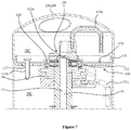
- a variant of the oil supply mechanism 100 is described with reference to Figures 7 , 8a, and 8b .
- the partition member 120 of the oil supply mechanism 100 is not manufactured by the deep drawing process and the partition member body 121 of the partition member 120 is substantially straight.
- the first oil inlet-pipe 162a for the first pump 162 and the second oil inlet-pipe 164a for the second pump 164 are not pipes (for example, straight pipes) extending substantially vertically downward from the pump-bearing seat assembly but bent pipes connected by, for example, brazing.
- the partition member 120 is similarly provided with the annular groove 128 opening toward the oil storage chamber OC, advantageous effects similar to the above exemplary embodiments can also be achieved.
- the split-type oil discharge pipe 162b located outside the pump-bearing seat assembly is also provided, a functional test (quality inspection) can also be conveniently performed on the first pump 162, and, compared with a solution in which an oil discharge passage is provided inside the pump-bearing seat assembly, the structure is also simplified and improper increase in the axial length of the pump-bearing seat assembly (especially the bearing seat) due to the provision of the oil discharge passage inside the pump-bearing seat assembly is avoided.
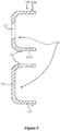
- partition member 120 is also an integral part formed by the deep drawing process, but the partition member 120 does not include the bent portion and the extending direction of the inner flange portion 122' is different.
- the partition member 120 includes a partition member body 121, an inner flange portion 122' serving as a radially inner portion of the partition member 120, and an outer flange portion 123 serving as a radially outer portion of the partition member 120, wherein the inner flange portion 122' and the outer flange portion 123 extend toward the oil storage chamber OC, and, the partition member body 121, the inner flange portion 122', and the outer flange portion 123 thereby together define the annular groove 128.
- advantageous effects similar to the above exemplary embodiments can also be achieved.
- the oil supply mechanism 100 may also have other possible variants.
- the partition member 120 may not be provided with the annular groove 128 opening toward the oil storage chamber OC but be provided with a split-type oil discharge pipe 162b located outside the pump-bearing seat assembly.
- one or more technical features described above may be incorporated in the technical solution that the annular groove 128 is not provided but the split-type oil discharge pipe 162b located outside the pump-bearing seat assembly is provided, as long as this incorporation is technically compatible.
Landscapes
- Engineering & Computer Science (AREA)
- Mechanical Engineering (AREA)
- General Engineering & Computer Science (AREA)
- Applications Or Details Of Rotary Compressors (AREA)
- Rotary Pumps (AREA)
- Compressor (AREA)
Abstract
Description
- This application claims priority to Chinese Patent Application No.
201721861898.7 - The present disclosure relates to the field of compressor, and in particular to a horizontal scroll compressor having an improvement on its oil supply mechanism.
- A compressor generally includes a housing, a compression mechanism housed in the housing, a motor that provides power to the compression mechanism, a rotating shaft driven by the motor, and an oil supply mechanism that supplies lubricating oil to various moving parts of the compressor. For a vertical compressor, an oil sump is generally provided at the bottom of the compressor housing and an oil pump is provided at the bottom end of the rotating shaft to pump the lubricating oil preserved in the oil sump to an oilhole axially extending in the rotating shaft, thereby supplying lubricating oil to the various moving parts of the compressor.
- However, in some applications, due to, for example, space limitations, a horizontal compressor is required. Since the horizontal compressor cannot naturally form an oil sump at a tail end of the rotating shaft, some oil supply mechanisms for the horizontal compressor are provided to realize the preservation and delivery of lubricating oil. For example, for a high-pressure side compressor, a partition plate may be provided to separate out two compartments with a pressure difference (a discharge pressure difference) in the high-pressure region to form in the lower pressure compartment an oil sump which can rise by means of the pressure difference, so that the high-pressure lubricating oil can be delivered to the oil pump (a single oil pump) at the tail end of the rotating shaft. However, according to this arrangement, since the pressure drop varies under different working conditions, the oil supply is greatly affected by the working conditions, resulting in poor consistency of the oil supply throughout the whole operating range of the compressor. For another example, for a low-pressure side compressor, the high-temperature and high-pressure lubricating oil in the high-pressure region can be introduced into the oil pump at the tail end of the rotating shaft, and a double-layer housing can be used to form an oil sump in the low-pressure region, or a vertical and straight partition member can be used to separate out an individual oil sump in the low-pressure region. However, in these oil supply solutions for low-pressure side compressors, the operating performance of the compressor may be adversely affected or a restricting structure with a complicated structure for restricting the amount of oil supplied may be required due to the need to introduce the high-temperature and high-pressure lubricating oil from the high-pressure region, or at least the radial dimension is disadvantageously enlarged due to the need to provide the double-layer housing. As for the related solution in which the individual oil sump is separated out in the low-pressure region by means of the vertical and straight partition member, due to, for example, lack of consideration of fully exploiting free space in the motor chamber or lack of consideration of the operability of quality inspection of the oil pump, certain problems may exist therein.
- Here, it should be noted that, the technical contents provided in this section are only for facilitating understanding of the present disclosure, but do not necessarily constitute the prior art.
- A general summary of the present disclosure is provided in this section, rather than the full scope of the present disclosure or a comprehensive disclosure of all features of the present disclosure.
- An object of the present disclosure is to provide an oil supply mechanism capable of reducing or minimizing free space in a motor chamber.
- Another object of the present disclosure is to provide an oil supply mechanism capable of reducing the overall size of a horizontal compressor when the size of an oil storage chamber is fixed.
- Another object of the present disclosure is to provide an oil supply mechanism capable of reducing or minimizing the free space in the motor chamber while allowing a stable engagement of a partition member and a housing.
- Another object of the present disclosure is to provide an oil supply mechanism capable of achieving reliable and stable connection and sealing of a partition member and a bearing seat.
- Another object of the present disclosure is to provide an oil supply mechanism capable of achieving reducing or minimizing the free space in the motor chamber while appropriately avoiding interference with related components around the bearing seat.
- Another object of the present disclosure is to provide an oil supply mechanism through which a functional test can be conveniently performed on a pump structure.
- Another object of the present disclosure is to provide an oil supply mechanism capable of avoiding improperly increasing an axial length of a pump-bearing seat assembly.
- Another object of the present disclosure is to provide a horizontal compressor associated with the above oil supply mechanism.
- In order to achieve one or more of the above objects, according to one aspect of the present disclosure, an oil supply mechanism for a horizontal compressor is provided. The horizontal compressor includes a housing, a motor, a rotating shaft driven by the motor, and a bearing seat supporting the rotating shaft. The oil supply mechanism includes a partition member. The partition member is ring-shaped and has a central hole allowing the bearing seat to pass through, and the partition member is configured to separate out in the housing an oil storage chamber and a motor chamber in which the motor is provided. The partition member is configured to have an annular groove opened toward the oil storage chamber.
- In the oil supply mechanism, a radially outer portion of the partition member is connected to an inner peripheral surface of the housing and a radially inner portion of the partition member is connected to an outer peripheral surface of the bearing seat.
- In the oil supply mechanism, the housing includes a housing body and an end cover, and the radially outer portion of the partition member is connected to both the housing body and the end cover.
- In the oil supply mechanism, the partition member includes a partition member body, an inner flange portion serving as a radially inner portion of the partition member that extends away from the oil storage chamber, an outer flange portion serving as a radially outer portion of the partition member that extends toward the oil storage chamber, and a bent portion located between the partition member body and the inner flange portion and protruding toward the oil storage chamber. Thereby, the partition member body, the outer flange portion, and the bent portion together define the annular groove.
- In the oil supply mechanism, the partition member includes a partition member body, an inner flange portion serving as a radially inner portion of the partition member, and an outer flange portion serving as a radially outer portion of the partition member, wherein the inner flange portion and the outer flange portion extend toward the oil storage chamber, and, the partition member body, the inner flange portion, and the outer flange portion thereby together define the annular groove.
- In the oil supply mechanism, the oil supply mechanism further includes an annular sealing member provided between the radially inner portion of the partition member and the outer peripheral surface of the bearing seat.
- In the oil supply mechanism, a sealing member groove is provided on the inner peripheral surface of the radially inner portion of the partition member and/or on the outer peripheral surface of the bearing seat, and the annular sealing member is accommodated in the sealing member groove.
- In the oil supply mechanism, a ridge is provided on the outer peripheral surface of the radially outer portion of the partition member, and the ridge is interposed between the housing body and the end cover of the housing.
- In the oil supply mechanism, the partition member is an integral part formed by a deep drawing process.
- In the oil supply mechanism, the partition member is such configured that the partition member body of the partition member defining the annular groove is offset toward the motor chamber and is closer to one end of the motor.
- In the oil supply mechanism, the oil supply mechanism further includes a pump device attached to the bearing seat at one end of the rotating shaft, so that the pump device and the bearing seat constitute a pump-bearing seat assembly. The pump device includes a first pump configured to deliver the lubricating oil in the motor chamber to the oil storage chamber, and an oil discharge pipe for the first pump. A first port of the oil discharge pipe is connected to the pump-bearing seat assembly, and a second port of the oil discharge pipe enters the oil storage chamber through an opening provided at the partition member.
- In the oil supply mechanism, the oil supply mechanism further includes a pump device attached to the bearing seat at one end of the rotating shaft, so that the pump device and the bearing seat constitute a pump-bearing seat assembly. The pump device includes a first pump configured to deliver the lubricating oil in the motor chamber to the oil storage chamber, a second pump configured to deliver the lubricating oil in the oil storage chamber to the oilhole in the rotating shaft, a first oil inlet-pipe for the first pump and a second oil inlet-pipe for the second pump extending substantially vertically downward from the pump-bearing seat assembly on the motor chamber side and on the oil storage chamber side respectively.
- In the oil supply mechanism, the first oil inlet-pipe and/or the second oil inlet-pipe are detachably connected to the pump-bearing seat assembly.
- In the oil supply mechanism, the first oil inlet-pipe and/or the second oil inlet-pipe have a threaded structure, and thereby can be screwed to the pump-bearing seat assembly, or, the first oil inlet-pipe and/or the second oil inlet-pipe are fixed to the pump-bearing seat assembly by threaded fasteners and positioning pins.
- In the oil supply mechanism, the horizontal compressor further includes a bearing seat bracket for fixing the bearing seat and the partition member is a component different from the bearing seat bracket.
- In order to achieve one or more of the above objects, according to another aspect of the present disclosure, an oil supply mechanism for a horizontal compressor is provided. The horizontal compressor includes a housing, a motor, a rotating shaft driven by the motor, and a bearing seat supporting the rotating shaft. The oil supply mechanism includes a partition member and a pump device. The partition member is configured to separate out in the housing an oil storage chamber and a motor chamber in which the motor is provided, and the pump device is attached to the bearing seat at one end of the rotating shaft, so that the pump device and the bearing seat constitute a pump-bearing seat assembly. The pump device includes a first pump configured to deliver the lubricating oil in the motor chamber to the oil storage chamber and an oil discharge pipe for the first pump. A first port of the oil discharge pipe is connected to the pump-bearing seat assembly on the motor chamber side, and a second port of the oil discharge pipe enters the oil storage chamber from the motor chamber side through an opening provided at the partition member.
- In order to achieve one or more of the above objects, according to another aspect of the present disclosure, a horizontal compressor is provided. The horizontal compressor has an oil supply mechanism as described above.
- The horizontal compressor is a low-pressure side scroll compressor.
- According to the present disclosure, since the partition member defines the annular groove having a larger depth opening toward the oil storage chamber by, for example, a deep drawing process, it is possible to reduce or minimize the free space (useless free space) in the motor chamber, and thereby the overall size (especially the axial size) of the horizontal compressor can be reduced when the size of the oil storage chamber is fixed. In addition, by means of the partition member having the annular groove and the outer flange portion extending toward the oil storage chamber, it is possible to reduce or minimize the free space in the motor chamber while allowing the partition member to be respectively connected with the housing body and the end cover so as to realize a stable engagement of the partition member, the housing body and the end cover. In addition, by means of the partition member having the inner flange portion, it is possible to realize reliable and stable connection and sealing of the partition member and the bearing seat. In addition, by means of the partition member having the bent portion protruding toward the oil storage chamber, it is possible to reduce or minimize the free space in the motor chamber while appropriately avoiding interference with related components around the bearing seat.
- In addition, by providing the split-type oil discharge pipe located outside the pump-bearing seat assembly, the functional test (quality inspection) can be conveniently performed on the first pump, and, compared with a solution in which an oil discharge passage is provided inside the pump-bearing seat assembly, the structure is simplified and improper increase in the axial length of the pump-bearing seat assembly (especially the bearing seat) due to the provision of the oil discharge passage inside the pump-bearing seat assembly is avoided.
- The features and advantages of one or more embodiments of the present disclosure will become more readily understood from the following description with reference to the accompanying drawings in which:
-
Figure 1 is a longitudinal sectional view of a horizontal compressor having an oil supply mechanism according to an exemplary embodiment of the present disclosure; -
Figure 2 is a partial enlarged view of a portion of the longitudinal section shown inFigure 1 ; -
Figure 3 is a perspective exploded view of a portion of the horizontal compressor shown inFigure 1 ; -
Figure 4 is a perspective exploded view of another portion of the horizontal compressor shown inFigure 1 ; -
Figure 5 is a perspective view showing an oil supply mechanism of the horizontal compressor shown inFigure 1 and related components around the oil supply mechanism; -
Figure 6 is another perspective view showing the oil supply mechanism of the horizontal compressor shown inFigure 1 and related components around the oil supply mechanism; -
Figure 7 is a longitudinal sectional view showing a variant of the oil supply mechanism according to the present disclosure; -
Figures 8a is a perspective assembly view of the variant of the oil supply mechanism according to the present disclosure, andFigure 8b is a perspective exploded view of the variant of the oil supply mechanism according to the present disclosure; and -
Figure 9 is a schematic sectional view of another variant of a partition member of the oil supply mechanism according to the present disclosure. - The present disclosure is described in detail hereinafter by means of specific embodiments with reference to the accompanying drawings. The following detailed description of the present disclosure is for explanation only and is by no means intended to limit the present disclosure and the applications or usages thereof.
- First, the structure of a
horizontal compressor 10 having anoil supply mechanism 100 according to the present disclosure is briefly described with reference toFigure 1 . - In the illustrated example, the
horizontal compressor 10 is a low-pressure side scroll compressor. However, it is conceivable that theoil supply mechanism 100 according to the present disclosure may be applied to other horizontal compressors. - As shown in
Figure 1 , thehorizontal compressor 10 includes ahousing 20, amotor 30, a rotatingshaft 40 driven by themotor 30, and a bearingseat 50 supporting therotating shaft 40. Thehousing 20 includes ahousing body 20a, and afirst end cover 20b and asecond end cover 20c which are respectively provided at two ends of thehousing body 20a. In addition, thehorizontal compressor 10 further includes acompression mechanism 60 and a partition plate (muffler plate) 70. Thecompression mechanism 60 is driven by the rotatingshaft 40 to compress the working fluid (for example, refrigerant). Thepartition plate 70 separates the internal space defined by the housing 20 (specifically, by thehousing body 20a, thefirst end cover 20b, and thesecond end cover 20c) into a high-pressure region (located on the left side of thepartition plate 70 as shown inFigure 1 ) and a low-pressure region (located on the right side of thepartition plate 70 as shown inFigure 1 ). - Further referring to
Figures 2 to 4 , theoil supply mechanism 100 according to the exemplary embodiment of the present disclosure for thehorizontal compressor 10 includes apartition member 120. Thepartition member 120 is in a ring shape (for example, in a substantially circular ring shape) and has acentral hole 129 allowing the bearingseat 50 to pass through. Thepartition member 120 is configured to separate out in thehousing 20 an oil storage chamber OC and a motor chamber MC in which themotor 30 is provided. Here, it is conceivable that the oil storage chamber OC located on one side with respect to an axial direction and the motor chamber MC located on the other side with respect to the axial direction are both located in the low-pressure region. - Particularly, a radially outer portion of the
partition member 120 is connected to an innerperipheral surface 22 of thehousing 20 and a radially inner portion of thepartition member 120 is connected to an outerperipheral surface 52 of the bearingseat 50. Thereby, the oil storage chamber OC and the motor chamber MC are simply and reliably separated out in thehousing 20 by thepartition member 120. - In the illustrated example, the radially outer portion of the
partition member 120 is connected to both thehousing body 20a and thesecond end cover 20c. In this way, the three of thehousing body 20a, thesecond end cover 20c and thepartition member 120 can be more stably engaged together. - According to the present disclosure, the
partition member 120 is configured to have anannular groove 128 opening toward the oil storage chamber OC. - In the example shown in
Figures 1 to 4 , thepartition member 120 includes apartition member body 121, aninner flange portion 122 serving as a radially inner portion of thepartition member 120 that extends away from the oil storage chamber OC , anouter flange portion 123 serving as a radially outer portion of thepartition member 120 that extends toward the oil storage chamber OC , and a bent portion 124 provided between thepartition member body 121 and theinner flange portion 122 and protruding toward the oil storage chamber OC. Thereby, thepartition member body 121, theouter flange portion 123, and the bent portion 124 together define theannular groove 128. That is, theannular groove 128 is reliably formed by thepartition member 120 itself without resorting to other components such as the bearingseat 50. - A
ridge 123a is provided on an outer peripheral surface of the radially outer portion (that is, the outer flange portion 123) of thepartition member 120. Theridge 123a is interposed between thehousing body 20a and theend cover 20c of thehousing 20. In this way, after thehousing body 20a and thesecond end cover 20c are assembled together, the three of thehousing body 20a, thesecond end cover 20c and thepartition member 120 are conveniently, for example, welded together at theridge 123a from the outside of thehousing 20. - The
oil supply mechanism 100 further includes anannular sealing member 140 provided between the radially inner portion (that is, the inner flange portion 122) of thepartition member 120 and the outerperipheral surface 52 of the bearingseat 50. In this way, thepartition member 120 and the bearingseat 50 can be connected to each other by the annular sealing member 140 (herein, thepartition member 120 and the bearingseat 50 may or may not contact each other). Thereby, especially in a case that the radially outer portion of thepartition member 120 is connected to the innerperipheral surface 22 of thehousing 20, the connection and sealing between thepartition member 120 and the bearingseat 50 can be realized simply by means of theannular sealing member 140 without resorting to other fastening devices. - In some examples, a sealing
member groove 122a (shown inFigures 7 and9 ) may be provided on the inner peripheral surface of the radially inner portion of the partition member 120 (that is, the inner flange portion 122), and theannular sealing member 140 can be accommodated in the sealingmember groove 122a. In some other examples, a sealingmember groove 52a (shown inFigure 2 ) may be provided on the outerperipheral surface 52 of the bearingseat 50, and theannular sealing member 140 can be accommodated in the sealingmember groove 52a. In addition, it is conceivable that a sealing member groove for accommodating theannular sealing member 140 may be provided on both the inner peripheral surface of the radially inner portion of thepartition member 120 and the outerperipheral surface 52 of the bearingseat 50. Since the sealing member groove for accommodating theannular sealing member 140 is provided, the connection and sealing between thepartition member 120 and the bearingseat 50 can be further reliably achieved. - In a preferred example, the
partition member 120 is an integral part formed by a deep drawing process. - Particularly, through the deep drawing process, the
partition member 120 is such configured that thepartition member body 121 of thepartition member 120 defining theannular groove 128 is offset toward the motor chamber MC (offset toward the motor chamber MC relative to the flange portion or the bent portion) and is closer to one end of themotor 30. In other words, theannular groove 128 of thepartition member 120 can thereby have a greater depth. - Further referring to
Figures 5 ,6 ,8a and 8b , theoil supply mechanism 100 further includes apump device 160 attached to the bearingseat 50 at one end of the rotating shaft 40 (the end where the bearingseat 50 is provided). Thepump device 160 and the bearing seat 50 (which may be assembled together in advance) constitute a pump-bearing seat assembly. Thepump device 160 includes afirst pump 162 configured to deliver the lubricating oil in the motor chamber MC to the oil storage chamber OC. - An oil inlet-
pipe 162a and anoil discharge pipe 162b for thefirst pump 162 are provided. Particularly, a first port of theoil discharge pipe 162b is connected to the pump-bearing seat assembly on the motor chamber side, and a second port of theoil discharge pipe 162b enters the oil storage chamber OC from the motor chamber side through anopening 127 provided at thepartition member 120. By providing the split-typeoil discharge pipe 162b located outside the pump-bearing seating assembly, a functional test (quality inspection) can be conveniently performed on thefirst pump 162, and, compared with a solution in which an oil discharge passage is provided inside the pump-bearing seat assembly, the structure is simplified and improper increase in the axial length of the pump-bearing seat assembly (especially the bearing seat) due to the provision of the oil discharge passage inside the pump-bearing seat assembly is avoided. - The
pump device 160 furthers include asecond pump 164 configured to deliver the lubricating oil in the oil storage chamber OC to an oilhole 42 in therotating shaft 40. Thefirst pump 162 and thesecond pump 164 may be combined together (for example, sharing a partition plate therebetween) to form a so-called double pump structure. In addition, the pumpage (for example, capacity) of thefirst pump 162 may be greater than that of thesecond pump 164. - In the example shown in
Figure 1 , the first oil inlet-pipe 162a for thefirst pump 162 extends substantially vertically downward from the pump-bearing seat assembly on the motor chamber side (for example, a straight pipe), and the second oil inlet-pipe 164a for thesecond pump 164 extends substantially vertically downward from the pump-bearing seat assembly on the oil storage chamber side (for example, a straight pipe). With this double straight tube design, the structure can become more compact to reduce costs and the quality of the pump structure can be better controlled. - The first oil inlet-
pipe 162a and/or the second oil inlet-pipe 164a may be detachably connected to the pump-bearing seat assembly. Particularly, referring toFigure 6 , the first oil inlet-pipe 162a and/or the second oil inlet-pipe 164a have a threaded structure, and thereby can be screwed to the pump-bearing seat assembly, or, the first oil inlet-pipe 162a and/or the second oil inlet-pipe 164a are fixed to the pump-bearing seat assembly by threadedfasteners 174 and positioning pins 172, which facilitates assembly, disassembly and quality inspection of the first oil inlet-pipe 162a and the second oil inlet-pipe 164a. - The
horizontal compressor 10 may further include abearing seat bracket 59 for fixing the bearingseat 50. Thepartition member 120 is a different member from the bearingseat bracket 59. In other words, thepartition member 120 for defining the oil storage chamber OC is independent of thebearing seat bracket 59 for supporting the bearingseat 50. Thereby, the oil storage chamber OC can be formed more reliably, the stable support of the bearingseat 50 can be more reliably achieved, and the connection and sealing between thepartition member 120 and the bearingseat 50 is possible to be realized simply by theannular sealing member 140 without resorting to other fastening devices. - According to the exemplary embodiments of the present disclosure, since the partition member defines the annular groove having a larger depth opening toward the oil storage chamber by means of, for example, the deep drawing process, it is possible to reduce or minimize the free space (useless free space) in the motor chamber, and the overall size (especially the axial size) of the horizontal compressor can be reduced when the size of the oil storage chamber is fixed. In addition, by means of the partition member which has the annular groove and the outer flange portion extending toward the oil storage chamber, it is possible to reduce or minimize the free space in the motor chamber while allowing the partition member to be connected respectively with the housing body and the end cover so as to realize a stable engagement of the partition member, the housing body and the end cover. In addition, by means of the partition member having the inner flange portion, it is possible to realize reliable and stable connection and sealing of the partition member and the bearing seat. In addition, by means of the partition member having the bent portion protruding toward the oil storage chamber, it is possible to reduce or minimize the free space in the motor chamber while appropriately avoiding interference with related components around the bearing seat.
- A variant of the
oil supply mechanism 100 is described with reference toFigures 7 ,8a, and 8b . In this variant, thepartition member 120 of theoil supply mechanism 100 is not manufactured by the deep drawing process and thepartition member body 121 of thepartition member 120 is substantially straight. Besides, in this variant, the first oil inlet-pipe 162a for thefirst pump 162 and the second oil inlet-pipe 164a for thesecond pump 164 are not pipes (for example, straight pipes) extending substantially vertically downward from the pump-bearing seat assembly but bent pipes connected by, for example, brazing. However, in this variant, since thepartition member 120 is similarly provided with theannular groove 128 opening toward the oil storage chamber OC, advantageous effects similar to the above exemplary embodiments can also be achieved. Besides, in this variant, the split-typeoil discharge pipe 162b located outside the pump-bearing seat assembly is also provided, a functional test (quality inspection) can also be conveniently performed on thefirst pump 162, and, compared with a solution in which an oil discharge passage is provided inside the pump-bearing seat assembly, the structure is also simplified and improper increase in the axial length of the pump-bearing seat assembly (especially the bearing seat) due to the provision of the oil discharge passage inside the pump-bearing seat assembly is avoided. - Another variant of the
partition member 120 according to the present disclosure is described below with reference toFigure 9 . In this variant, compared with the above exemplary embodiments, thepartition member 120 is also an integral part formed by the deep drawing process, but thepartition member 120 does not include the bent portion and the extending direction of the inner flange portion 122' is different. Specifically, in this variant, thepartition member 120 includes apartition member body 121, an inner flange portion 122' serving as a radially inner portion of thepartition member 120, and anouter flange portion 123 serving as a radially outer portion of thepartition member 120, wherein the inner flange portion 122' and theouter flange portion 123 extend toward the oil storage chamber OC, and, thepartition member body 121, the inner flange portion 122', and theouter flange portion 123 thereby together define theannular groove 128. According to this variant, advantageous effects similar to the above exemplary embodiments can also be achieved. - The
oil supply mechanism 100 according to the present disclosure may also have other possible variants. For example, thepartition member 120 may not be provided with theannular groove 128 opening toward the oil storage chamber OC but be provided with a split-typeoil discharge pipe 162b located outside the pump-bearing seat assembly. Moreover, one or more technical features described above may be incorporated in the technical solution that theannular groove 128 is not provided but the split-typeoil discharge pipe 162b located outside the pump-bearing seat assembly is provided, as long as this incorporation is technically compatible. - Although the present disclosure has been described with reference to the exemplary specific embodiments, it should be understood that the present disclosure is not limited to the specific embodiments described and illustrated in detail herein. Those skilled in the art can make various modifications to the exemplary specific embodiments without departing from the scope defined by the claims.
Claims (18)
- An oil supply mechanism (100) for a horizontal compressor (10), wherein the horizontal compressor (10) comprises a housing (20), a motor (30), and a rotating shaft (40) driven by the motor (30), and a bearing seat (50) supporting the rotating shaft (40),
the oil supply mechanism (100) comprises a partition member (120), the partition member (120) is ring-shaped and has a central hole (129) allowing the bearing seat (50) to pass through, and the partition member (120) is configured to separate out in the housing (20) an oil storage chamber (OC) and a motor chamber (MC) in which the motor (30) is provided,
characterized in that the partition member (120) is configured to have an annular groove (128) opening toward the oil storage chamber (OC). - The oil supply mechanism (100) according to claim 1, wherein a radially outer portion of the partition member (120) is connected to an inner peripheral surface (22) of the housing (20) and a radially inner portion of the partition member (120) is connected to an outer peripheral surface (52) of the bearing seat (50).
- The oil supply mechanism (100) according to claim 1, wherein the housing (20) comprises a housing body (20a) and an end cover (20c), and a radially outer portion of the partition member (120) is connected to both the housing body (20a) and the end cover (20c).
- The oil supply mechanism (100) according to claim 1, wherein the partition member (120) comprises a partition member body (121), an inner flange portion serving as a radially inner portion of the partition member (120) that extends away from the oil storage chamber (OC), an outer flange portion (123) serving as a radially outer portion of the partition member (120) that extends toward the oil storage chamber (OC), and a bent portion (124) provided between the partition member body (121) and the inner flange portion and protruding toward the oil storage chamber (OC), thereby the partition member body (121), the outer flange portion (123), and the bent portion (124) together define the annular groove (128).
- The oil supply mechanism (100) according to claim 1, wherein the partition member (120) comprises a partition member body (121), an inner flange portion serving as a radially inner portion of the partition member (120), and an outer flange portion (123) serving as a radially outer portion of the partition member (120), the inner flange portion and the outer flange portion (123) extend toward the oil storage chamber (OC), thereby the partition member body (121), the inner flange portion, and the outer flange portion (123) together define the annular groove (128).
- The oil supply mechanism (100) according to any one of claims 2 to 5, wherein the oil supply mechanism (100) further comprises an annular sealing member (140) provided between the radially inner portion of the partition member (120) and the outer peripheral surface (52) of the bearing seat (50).
- The oil supply mechanism (100) according to claim 6, wherein a sealing member groove (122a, 52a) is provided on an inner peripheral surface of the radially inner portion of the partition member (120) and/or on the outer peripheral surface (52) of the bearing seat (50), and the annular sealing member (140) is accommodated in the sealing member groove (122a, 52a).
- The oil supply mechanism (100) according to any one of claims 2 to 5, wherein a ridge (123a) is provided on an outer peripheral surface of the radially outer portion of the partition member (120), and the ridge (123a) is interposed between a housing body (20a) and an end cover (20c) of the housing (20).
- The oil supply mechanism (100) according to any one of claims 1 to 5, wherein the partition member (120) is an integral part formed by a deep drawing process.
- The oil supply mechanism (100) according to claim 9, wherein the partition member (120) is such configured that a partition member body (121) of the partition member (120) defining the annular groove (128) is offset toward the motor chamber (MC) and is closer to one end of the motor (30).
- The oil supply mechanism (100) according to any one of claims 1 to 5, wherein:the oil supply mechanism (100) further comprises a pump device (160) which is attached to the bearing seat (50) at one end of the rotating shaft (40), the pump device (160) and the bearing seat (50) constitute a pump-bearing seat assembly, and the pump device (160) comprises a first pump (162) configured to deliver lubricating oil in the motor chamber (MC) to the oil storage chamber (OC), andthe oil supply mechanism (100) is provided with an oil discharge pipe (162b) for the first pump (162), a first port of the oil discharge pipe (162b) is connected to the pump-bearing seat assembly, and a second port of the oil discharge pipe (162b) enters the oil storage chamber (OC) through an opening (127) provided at the partition member (120).
- The oil supply mechanism (100) according to any one of claims 1 to 5, wherein:the oil supply mechanism (100) further comprises a pump device (160) attached to the bearing seat (50) at one end of the rotating shaft (40), the pump device (160) and the bearing seat (50) constitute a pump-bearing seat assembly, the pump device (160) comprises a first pump (162) configured to deliver lubricating oil in the motor chamber (MC) to the oil storage chamber (OC) and a second pump (164) configured to deliver lubricating oil in the oil storage chamber (OC) to an oilhole (42) in the rotating shaft (40), anda first oil inlet-pipe (162a) for the first pump (162) and a second oil inlet-pipe (164a) for the second pump (164) extend substantially vertically downward from the pump-bearing seat assembly on a motor chamber side and on an oil storage chamber side respectively.
- The oil supply mechanism (100) according to claim 12, wherein the first oil inlet-pipe (162a) and/or the second oil inlet-pipe (164a) are detachably connected to the pump-bearing seat assembly.
- The oil supply mechanism (100) according to claim 13, wherein
the first oil inlet-pipe (162a) and/or the second oil inlet-pipe (164a) have a threaded structure and are screwed to the pump-bearing seat assembly, or,
the first oil inlet-pipe (162a) and/or the second oil inlet-pipe (164a) are fixed to the pump-bearing seat assembly by a threaded fastener (174) and a positioning pin (172). - The oil supply mechanism (100) according to any one of claims 1 to 5, wherein the horizontal compressor (10) further comprises a bearing seat bracket (59) for fixing the bearing seat (50), and the partition member (120) is a member different from the bearing seat bracket (59).
- An oil supply mechanism (100) for a horizontal compressor (10), wherein the horizontal compressor (10) comprises a housing (20), a motor (30), and a rotating shaft (40) driven by the motor (30), and a bearing seat (50) supporting the rotating shaft (40),
the oil supply mechanism (100) comprises a partition member (120) and a pump device (160), the partition member (120) is configured to separate out in the housing (20) an oil storage chamber (OC) and a motor chamber (MC) in which the motor (30) is provided, the pump device (160) is attached to the bearing seat (50) at one end of the rotating shaft (40), the pump device (160) and the bearing seat (50) constitute a pump-bearing seat assembly, and the pump device (160) comprises a first pump (162) configured to deliver lubricating oil in the motor chamber (MC) to the oil storage chamber (OC),
characterized in that an oil discharge pipe (162b) for the first pump (162) is provided, a first port of the oil discharge pipe (162b) is connected to the pump-bearing seat assembly on a motor chamber side, and a second port of the oil discharge pipe (162b) enters the oil storage chamber (OC) from the motor chamber side through an opening (127) provided at the partition member (120). - A horizontal compressor (10), characterized by comprising the oil supply mechanism (100) according to any one of claims 1 to 16.
- The horizontal compressor (10) according to claim 17, characterized in that the horizontal compressor (10) is a low-pressure side scroll compressor.
Applications Claiming Priority (2)
| Application Number | Priority Date | Filing Date | Title |
|---|---|---|---|
| CN201721861898.7U CN207795583U (en) | 2017-12-27 | 2017-12-27 | Oil supply mechanism and horizontal compressor with same |
| PCT/CN2018/123893 WO2019129057A1 (en) | 2017-12-27 | 2018-12-26 | Oil supplying mechanism, and horizontal compressor having same |
Publications (4)
| Publication Number | Publication Date |
|---|---|
| EP3734076A1 true EP3734076A1 (en) | 2020-11-04 |
| EP3734076A4 EP3734076A4 (en) | 2021-06-09 |
| EP3734076C0 EP3734076C0 (en) | 2023-12-20 |
| EP3734076B1 EP3734076B1 (en) | 2023-12-20 |
Family
ID=63279359
Family Applications (1)
| Application Number | Title | Priority Date | Filing Date |
|---|---|---|---|
| EP18893372.5A Active EP3734076B1 (en) | 2017-12-27 | 2018-12-26 | Oil supplying mechanism, and horizontal compressor having same |
Country Status (4)
| Country | Link |
|---|---|
| US (1) | US11603843B2 (en) |
| EP (1) | EP3734076B1 (en) |
| CN (1) | CN207795583U (en) |
| WO (1) | WO2019129057A1 (en) |
Families Citing this family (3)
| Publication number | Priority date | Publication date | Assignee | Title |
|---|---|---|---|---|
| CN207795583U (en) | 2017-12-27 | 2018-08-31 | 艾默生环境优化技术(苏州)有限公司 | Oil supply mechanism and horizontal compressor with same |
| CN112930442B (en) | 2018-09-28 | 2024-02-09 | 谷轮有限合伙公司 | Compressor oil management system |
| US11953001B2 (en) | 2021-07-15 | 2024-04-09 | Samsung Electronics Co., Ltd. | Horizontal type rotary compressor and home appliance including the same |
Family Cites Families (16)
| Publication number | Priority date | Publication date | Assignee | Title |
|---|---|---|---|---|
| US3434656A (en) * | 1967-09-14 | 1969-03-25 | Worthington Corp | Lubrication system for rotary vane compressors |
| JP2895320B2 (en) * | 1992-06-12 | 1999-05-24 | 三菱重工業株式会社 | Horizontal hermetic compressor |
| JP3408309B2 (en) * | 1994-02-10 | 2003-05-19 | 株式会社東芝 | Hermetic compressor and refrigeration system using this compressor |
| TW316940B (en) * | 1994-09-16 | 1997-10-01 | Hitachi Ltd | |
| TW362142B (en) * | 1996-05-23 | 1999-06-21 | Sanyo Electric Co | Horizontal compressor |
| JP3874469B2 (en) * | 1996-10-04 | 2007-01-31 | 株式会社日立製作所 | Scroll compressor |
| JP3956432B2 (en) * | 1997-06-18 | 2007-08-08 | 松下電器産業株式会社 | Hermetic compressor |
| JP4152678B2 (en) * | 2002-06-13 | 2008-09-17 | 松下電器産業株式会社 | Scroll compressor |
| JP2007218214A (en) * | 2006-02-20 | 2007-08-30 | Hitachi Ltd | Hermetic scroll compressor |
| JP2008008161A (en) * | 2006-06-27 | 2008-01-17 | Sanden Corp | Compressor |
| DE102008013784B4 (en) * | 2007-03-15 | 2017-03-23 | Denso Corporation | compressor |
| JP5150564B2 (en) * | 2009-06-22 | 2013-02-20 | 日立アプライアンス株式会社 | Horizontal hermetic compressor |
| JP5277283B2 (en) * | 2011-05-13 | 2013-08-28 | 日立アプライアンス株式会社 | Scroll compressor and refrigeration cycle equipped with the same |
| CN106812701B (en) * | 2015-12-02 | 2019-04-16 | 上海海立电器有限公司 | Compressor housing and horizontal compressor |
| CN205578273U (en) * | 2016-05-03 | 2016-09-14 | 艾默生环境优化技术(苏州)有限公司 | Oil pumping mechanism and horizontal compressor with same |
| CN207795583U (en) * | 2017-12-27 | 2018-08-31 | 艾默生环境优化技术(苏州)有限公司 | Oil supply mechanism and horizontal compressor with same |
-
2017
- 2017-12-27 CN CN201721861898.7U patent/CN207795583U/en active Active
-
2018
- 2018-12-26 US US16/957,698 patent/US11603843B2/en active Active
- 2018-12-26 EP EP18893372.5A patent/EP3734076B1/en active Active
- 2018-12-26 WO PCT/CN2018/123893 patent/WO2019129057A1/en unknown
Also Published As
| Publication number | Publication date |
|---|---|
| CN207795583U (en) | 2018-08-31 |
| US20200362863A1 (en) | 2020-11-19 |
| US11603843B2 (en) | 2023-03-14 |
| EP3734076C0 (en) | 2023-12-20 |
| EP3734076A4 (en) | 2021-06-09 |
| WO2019129057A1 (en) | 2019-07-04 |
| EP3734076B1 (en) | 2023-12-20 |
Similar Documents
| Publication | Publication Date | Title |
|---|---|---|
| EP3734076A1 (en) | Oil supplying mechanism, and horizontal compressor having same | |
| US10167867B2 (en) | Scroll fluid machine having tip seal member separated into different portions | |
| US20140178232A1 (en) | Scroll compressor | |
| CN205578273U (en) | Oil pumping mechanism and horizontal compressor with same | |
| US9651047B2 (en) | Compressor having a partitioned discharge chamber | |
| JP2015036513A (en) | Scroll compressor | |
| JP5880513B2 (en) | Compressor | |
| JP2013079591A (en) | Supercharger | |
| US11913455B2 (en) | Scroll compressor having a centrifugal oil pump | |
| EP2236829B1 (en) | Sealed-type scroll compressor | |
| US9897088B2 (en) | Scroll compressor with back pressure chamber having leakage channel | |
| CN109642570A (en) | Screw compressor | |
| JP2015090093A (en) | Scroll compressor | |
| US11131304B2 (en) | Scroll compressor and method for producing same | |
| AU2017251203B2 (en) | Hermetic two-stage compressor | |
| CN202040082U (en) | Vortex compressor | |
| EP3978754A1 (en) | Scroll compressor | |
| JP2012154266A (en) | Rotary compressor and method of manufacturing the same | |
| WO2020143350A1 (en) | Thrust plate for scroll compressor, and scroll compressor | |
| JP2008111389A (en) | Scroll type compressor | |
| EP3617502A1 (en) | Rolling-cylinder-type displacement compressor | |
| US20220372976A1 (en) | Scroll compressor | |
| US12000392B2 (en) | Scroll compressor | |
| JP2009115100A (en) | Scroll compressor | |
| JP2018112130A (en) | Compressor |
Legal Events
| Date | Code | Title | Description |
|---|---|---|---|
| STAA | Information on the status of an ep patent application or granted ep patent |
Free format text: STATUS: THE INTERNATIONAL PUBLICATION HAS BEEN MADE |
|
| PUAI | Public reference made under article 153(3) epc to a published international application that has entered the european phase |
Free format text: ORIGINAL CODE: 0009012 |
|
| STAA | Information on the status of an ep patent application or granted ep patent |
Free format text: STATUS: REQUEST FOR EXAMINATION WAS MADE |
|
| 17P | Request for examination filed |
Effective date: 20200703 |
|
| AK | Designated contracting states |
Kind code of ref document: A1 Designated state(s): AL AT BE BG CH CY CZ DE DK EE ES FI FR GB GR HR HU IE IS IT LI LT LU LV MC MK MT NL NO PL PT RO RS SE SI SK SM TR |
|
| AX | Request for extension of the european patent |
Extension state: BA ME |
|
| DAV | Request for validation of the european patent (deleted) | ||
| DAX | Request for extension of the european patent (deleted) | ||
| A4 | Supplementary search report drawn up and despatched |
Effective date: 20210507 |
|
| RIC1 | Information provided on ipc code assigned before grant |
Ipc: F04C 29/02 20060101AFI20210430BHEP Ipc: F04C 23/00 20060101ALI20210430BHEP |
|
| GRAP | Despatch of communication of intention to grant a patent |
Free format text: ORIGINAL CODE: EPIDOSNIGR1 |
|
| STAA | Information on the status of an ep patent application or granted ep patent |
Free format text: STATUS: GRANT OF PATENT IS INTENDED |
|
| INTG | Intention to grant announced |
Effective date: 20230630 |
|
| GRAS | Grant fee paid |
Free format text: ORIGINAL CODE: EPIDOSNIGR3 |
|
| GRAA | (expected) grant |
Free format text: ORIGINAL CODE: 0009210 |
|
| STAA | Information on the status of an ep patent application or granted ep patent |
Free format text: STATUS: THE PATENT HAS BEEN GRANTED |
|
| AK | Designated contracting states |
Kind code of ref document: B1 Designated state(s): AL AT BE BG CH CY CZ DE DK EE ES FI FR GB GR HR HU IE IS IT LI LT LU LV MC MK MT NL NO PL PT RO RS SE SI SK SM TR |
|
| REG | Reference to a national code |
Ref country code: GB Ref legal event code: FG4D |
|
| REG | Reference to a national code |
Ref country code: CH Ref legal event code: EP |
|
| REG | Reference to a national code |
Ref country code: DE Ref legal event code: R096 Ref document number: 602018063057 Country of ref document: DE |
|
| REG | Reference to a national code |
Ref country code: IE Ref legal event code: FG4D |
|
| RAP4 | Party data changed (patent owner data changed or rights of a patent transferred) |
Owner name: COPELAND CLIMATE TECHNOLOGIES (SUZHOU) CO., LTD. |
|
| U01 | Request for unitary effect filed |
Effective date: 20240112 |
|
| U07 | Unitary effect registered |
Designated state(s): AT BE BG DE DK EE FI FR IT LT LU LV MT NL PT SE SI Effective date: 20240123 |
|
| PG25 | Lapsed in a contracting state [announced via postgrant information from national office to epo] |
Ref country code: GR Free format text: LAPSE BECAUSE OF FAILURE TO SUBMIT A TRANSLATION OF THE DESCRIPTION OR TO PAY THE FEE WITHIN THE PRESCRIBED TIME-LIMIT Effective date: 20240321 |
|
| PG25 | Lapsed in a contracting state [announced via postgrant information from national office to epo] |
Ref country code: ES Free format text: LAPSE BECAUSE OF FAILURE TO SUBMIT A TRANSLATION OF THE DESCRIPTION OR TO PAY THE FEE WITHIN THE PRESCRIBED TIME-LIMIT Effective date: 20231220 |
|
| PG25 | Lapsed in a contracting state [announced via postgrant information from national office to epo] |
Ref country code: GR Free format text: LAPSE BECAUSE OF FAILURE TO SUBMIT A TRANSLATION OF THE DESCRIPTION OR TO PAY THE FEE WITHIN THE PRESCRIBED TIME-LIMIT Effective date: 20240321 Ref country code: ES Free format text: LAPSE BECAUSE OF FAILURE TO SUBMIT A TRANSLATION OF THE DESCRIPTION OR TO PAY THE FEE WITHIN THE PRESCRIBED TIME-LIMIT Effective date: 20231220 |