EP3734022B1 - Moteur à turbine à gaz ayant une meilleure résistance au pliage - Google Patents
Moteur à turbine à gaz ayant une meilleure résistance au pliage Download PDFInfo
- Publication number
- EP3734022B1 EP3734022B1 EP20170563.9A EP20170563A EP3734022B1 EP 3734022 B1 EP3734022 B1 EP 3734022B1 EP 20170563 A EP20170563 A EP 20170563A EP 3734022 B1 EP3734022 B1 EP 3734022B1
- Authority
- EP
- European Patent Office
- Prior art keywords
- fan
- flange
- engine
- core
- gas turbine
- Prior art date
- Legal status (The legal status is an assumption and is not a legal conclusion. Google has not performed a legal analysis and makes no representation as to the accuracy of the status listed.)
- Active
Links
- 238000005452 bending Methods 0.000 title description 21
- 238000011144 upstream manufacturing Methods 0.000 claims description 27
- RTAQQCXQSZGOHL-UHFFFAOYSA-N Titanium Chemical compound [Ti] RTAQQCXQSZGOHL-UHFFFAOYSA-N 0.000 claims description 7
- 239000002131 composite material Substances 0.000 claims description 7
- 239000010936 titanium Substances 0.000 claims description 7
- 229910052719 titanium Inorganic materials 0.000 claims description 7
- 239000007769 metal material Substances 0.000 claims description 6
- 238000000926 separation method Methods 0.000 claims description 6
- 229910001148 Al-Li alloy Inorganic materials 0.000 claims description 5
- FCVHBUFELUXTLR-UHFFFAOYSA-N [Li].[AlH3] Chemical compound [Li].[AlH3] FCVHBUFELUXTLR-UHFFFAOYSA-N 0.000 claims description 5
- 239000001989 lithium alloy Substances 0.000 claims description 5
- 239000000463 material Substances 0.000 description 8
- 230000004323 axial length Effects 0.000 description 5
- 238000002485 combustion reaction Methods 0.000 description 4
- 238000010586 diagram Methods 0.000 description 4
- 230000001141 propulsive effect Effects 0.000 description 4
- 239000004411 aluminium Substances 0.000 description 3
- 229910052782 aluminium Inorganic materials 0.000 description 3
- XAGFODPZIPBFFR-UHFFFAOYSA-N aluminium Chemical compound [Al] XAGFODPZIPBFFR-UHFFFAOYSA-N 0.000 description 3
- 230000006835 compression Effects 0.000 description 3
- 238000007906 compression Methods 0.000 description 3
- 239000000835 fiber Substances 0.000 description 3
- 229910052751 metal Inorganic materials 0.000 description 3
- 239000002184 metal Substances 0.000 description 3
- 238000000034 method Methods 0.000 description 3
- OKTJSMMVPCPJKN-UHFFFAOYSA-N Carbon Chemical compound [C] OKTJSMMVPCPJKN-UHFFFAOYSA-N 0.000 description 2
- 229910052799 carbon Inorganic materials 0.000 description 2
- 238000006243 chemical reaction Methods 0.000 description 2
- 239000000446 fuel Substances 0.000 description 2
- 238000004519 manufacturing process Methods 0.000 description 2
- 239000011159 matrix material Substances 0.000 description 2
- 239000011156 metal matrix composite Substances 0.000 description 2
- 230000003068 static effect Effects 0.000 description 2
- 238000003466 welding Methods 0.000 description 2
- 229910000831 Steel Inorganic materials 0.000 description 1
- 229910045601 alloy Inorganic materials 0.000 description 1
- 239000000956 alloy Substances 0.000 description 1
- 230000009286 beneficial effect Effects 0.000 description 1
- DGLFSNZWRYADFC-UHFFFAOYSA-N chembl2334586 Chemical compound C1CCC2=CN=C(N)N=C2C2=C1NC1=CC=C(C#CC(C)(O)C)C=C12 DGLFSNZWRYADFC-UHFFFAOYSA-N 0.000 description 1
- 230000003247 decreasing effect Effects 0.000 description 1
- 238000009826 distribution Methods 0.000 description 1
- 230000000694 effects Effects 0.000 description 1
- 238000007689 inspection Methods 0.000 description 1
- 238000012423 maintenance Methods 0.000 description 1
- 239000000203 mixture Substances 0.000 description 1
- 230000001681 protective effect Effects 0.000 description 1
- 239000010959 steel Substances 0.000 description 1
Images


Classifications
-
- F—MECHANICAL ENGINEERING; LIGHTING; HEATING; WEAPONS; BLASTING
- F01—MACHINES OR ENGINES IN GENERAL; ENGINE PLANTS IN GENERAL; STEAM ENGINES
- F01D—NON-POSITIVE DISPLACEMENT MACHINES OR ENGINES, e.g. STEAM TURBINES
- F01D5/00—Blades; Blade-carrying members; Heating, heat-insulating, cooling or antivibration means on the blades or the members
- F01D5/12—Blades
- F01D5/14—Form or construction
-
- B—PERFORMING OPERATIONS; TRANSPORTING
- B64—AIRCRAFT; AVIATION; COSMONAUTICS
- B64D—EQUIPMENT FOR FITTING IN OR TO AIRCRAFT; FLIGHT SUITS; PARACHUTES; ARRANGEMENT OR MOUNTING OF POWER PLANTS OR PROPULSION TRANSMISSIONS IN AIRCRAFT
- B64D29/00—Power-plant nacelles, fairings, or cowlings
- B64D29/06—Attaching of nacelles, fairings or cowlings
-
- F—MECHANICAL ENGINEERING; LIGHTING; HEATING; WEAPONS; BLASTING
- F01—MACHINES OR ENGINES IN GENERAL; ENGINE PLANTS IN GENERAL; STEAM ENGINES
- F01D—NON-POSITIVE DISPLACEMENT MACHINES OR ENGINES, e.g. STEAM TURBINES
- F01D25/00—Component parts, details, or accessories, not provided for in, or of interest apart from, other groups
- F01D25/16—Arrangement of bearings; Supporting or mounting bearings in casings
- F01D25/162—Bearing supports
-
- F—MECHANICAL ENGINEERING; LIGHTING; HEATING; WEAPONS; BLASTING
- F01—MACHINES OR ENGINES IN GENERAL; ENGINE PLANTS IN GENERAL; STEAM ENGINES
- F01D—NON-POSITIVE DISPLACEMENT MACHINES OR ENGINES, e.g. STEAM TURBINES
- F01D25/00—Component parts, details, or accessories, not provided for in, or of interest apart from, other groups
- F01D25/24—Casings; Casing parts, e.g. diaphragms, casing fastenings
- F01D25/243—Flange connections; Bolting arrangements
-
- F—MECHANICAL ENGINEERING; LIGHTING; HEATING; WEAPONS; BLASTING
- F01—MACHINES OR ENGINES IN GENERAL; ENGINE PLANTS IN GENERAL; STEAM ENGINES
- F01D—NON-POSITIVE DISPLACEMENT MACHINES OR ENGINES, e.g. STEAM TURBINES
- F01D25/00—Component parts, details, or accessories, not provided for in, or of interest apart from, other groups
- F01D25/28—Supporting or mounting arrangements, e.g. for turbine casing
-
- F—MECHANICAL ENGINEERING; LIGHTING; HEATING; WEAPONS; BLASTING
- F02—COMBUSTION ENGINES; HOT-GAS OR COMBUSTION-PRODUCT ENGINE PLANTS
- F02C—GAS-TURBINE PLANTS; AIR INTAKES FOR JET-PROPULSION PLANTS; CONTROLLING FUEL SUPPLY IN AIR-BREATHING JET-PROPULSION PLANTS
- F02C3/00—Gas-turbine plants characterised by the use of combustion products as the working fluid
- F02C3/04—Gas-turbine plants characterised by the use of combustion products as the working fluid having a turbine driving a compressor
- F02C3/107—Gas-turbine plants characterised by the use of combustion products as the working fluid having a turbine driving a compressor with two or more rotors connected by power transmission
- F02C3/113—Gas-turbine plants characterised by the use of combustion products as the working fluid having a turbine driving a compressor with two or more rotors connected by power transmission with variable power transmission between rotors
-
- F—MECHANICAL ENGINEERING; LIGHTING; HEATING; WEAPONS; BLASTING
- F02—COMBUSTION ENGINES; HOT-GAS OR COMBUSTION-PRODUCT ENGINE PLANTS
- F02C—GAS-TURBINE PLANTS; AIR INTAKES FOR JET-PROPULSION PLANTS; CONTROLLING FUEL SUPPLY IN AIR-BREATHING JET-PROPULSION PLANTS
- F02C7/00—Features, components parts, details or accessories, not provided for in, or of interest apart form groups F02C1/00 - F02C6/00; Air intakes for jet-propulsion plants
- F02C7/20—Mounting or supporting of plant; Accommodating heat expansion or creep
-
- F—MECHANICAL ENGINEERING; LIGHTING; HEATING; WEAPONS; BLASTING
- F02—COMBUSTION ENGINES; HOT-GAS OR COMBUSTION-PRODUCT ENGINE PLANTS
- F02C—GAS-TURBINE PLANTS; AIR INTAKES FOR JET-PROPULSION PLANTS; CONTROLLING FUEL SUPPLY IN AIR-BREATHING JET-PROPULSION PLANTS
- F02C7/00—Features, components parts, details or accessories, not provided for in, or of interest apart form groups F02C1/00 - F02C6/00; Air intakes for jet-propulsion plants
- F02C7/36—Power transmission arrangements between the different shafts of the gas turbine plant, or between the gas-turbine plant and the power user
-
- F—MECHANICAL ENGINEERING; LIGHTING; HEATING; WEAPONS; BLASTING
- F02—COMBUSTION ENGINES; HOT-GAS OR COMBUSTION-PRODUCT ENGINE PLANTS
- F02K—JET-PROPULSION PLANTS
- F02K3/00—Plants including a gas turbine driving a compressor or a ducted fan
- F02K3/02—Plants including a gas turbine driving a compressor or a ducted fan in which part of the working fluid by-passes the turbine and combustion chamber
- F02K3/04—Plants including a gas turbine driving a compressor or a ducted fan in which part of the working fluid by-passes the turbine and combustion chamber the plant including ducted fans, i.e. fans with high volume, low pressure outputs, for augmenting the jet thrust, e.g. of double-flow type
- F02K3/06—Plants including a gas turbine driving a compressor or a ducted fan in which part of the working fluid by-passes the turbine and combustion chamber the plant including ducted fans, i.e. fans with high volume, low pressure outputs, for augmenting the jet thrust, e.g. of double-flow type with front fan
-
- F—MECHANICAL ENGINEERING; LIGHTING; HEATING; WEAPONS; BLASTING
- F04—POSITIVE - DISPLACEMENT MACHINES FOR LIQUIDS; PUMPS FOR LIQUIDS OR ELASTIC FLUIDS
- F04D—NON-POSITIVE-DISPLACEMENT PUMPS
- F04D29/00—Details, component parts, or accessories
- F04D29/02—Selection of particular materials
- F04D29/023—Selection of particular materials especially adapted for elastic fluid pumps
-
- F—MECHANICAL ENGINEERING; LIGHTING; HEATING; WEAPONS; BLASTING
- F04—POSITIVE - DISPLACEMENT MACHINES FOR LIQUIDS; PUMPS FOR LIQUIDS OR ELASTIC FLUIDS
- F04D—NON-POSITIVE-DISPLACEMENT PUMPS
- F04D29/00—Details, component parts, or accessories
- F04D29/26—Rotors specially for elastic fluids
- F04D29/32—Rotors specially for elastic fluids for axial flow pumps
- F04D29/325—Rotors specially for elastic fluids for axial flow pumps for axial flow fans
-
- F—MECHANICAL ENGINEERING; LIGHTING; HEATING; WEAPONS; BLASTING
- F04—POSITIVE - DISPLACEMENT MACHINES FOR LIQUIDS; PUMPS FOR LIQUIDS OR ELASTIC FLUIDS
- F04D—NON-POSITIVE-DISPLACEMENT PUMPS
- F04D29/00—Details, component parts, or accessories
- F04D29/26—Rotors specially for elastic fluids
- F04D29/32—Rotors specially for elastic fluids for axial flow pumps
- F04D29/38—Blades
- F04D29/388—Blades characterised by construction
-
- F—MECHANICAL ENGINEERING; LIGHTING; HEATING; WEAPONS; BLASTING
- F04—POSITIVE - DISPLACEMENT MACHINES FOR LIQUIDS; PUMPS FOR LIQUIDS OR ELASTIC FLUIDS
- F04D—NON-POSITIVE-DISPLACEMENT PUMPS
- F04D29/00—Details, component parts, or accessories
- F04D29/40—Casings; Connections of working fluid
- F04D29/52—Casings; Connections of working fluid for axial pumps
- F04D29/54—Fluid-guiding means, e.g. diffusers
- F04D29/541—Specially adapted for elastic fluid pumps
- F04D29/542—Bladed diffusers
-
- F—MECHANICAL ENGINEERING; LIGHTING; HEATING; WEAPONS; BLASTING
- F16—ENGINEERING ELEMENTS AND UNITS; GENERAL MEASURES FOR PRODUCING AND MAINTAINING EFFECTIVE FUNCTIONING OF MACHINES OR INSTALLATIONS; THERMAL INSULATION IN GENERAL
- F16H—GEARING
- F16H1/00—Toothed gearings for conveying rotary motion
- F16H1/28—Toothed gearings for conveying rotary motion with gears having orbital motion
-
- F—MECHANICAL ENGINEERING; LIGHTING; HEATING; WEAPONS; BLASTING
- F05—INDEXING SCHEMES RELATING TO ENGINES OR PUMPS IN VARIOUS SUBCLASSES OF CLASSES F01-F04
- F05D—INDEXING SCHEME FOR ASPECTS RELATING TO NON-POSITIVE-DISPLACEMENT MACHINES OR ENGINES, GAS-TURBINES OR JET-PROPULSION PLANTS
- F05D2220/00—Application
- F05D2220/30—Application in turbines
- F05D2220/32—Application in turbines in gas turbines
-
- F—MECHANICAL ENGINEERING; LIGHTING; HEATING; WEAPONS; BLASTING
- F05—INDEXING SCHEMES RELATING TO ENGINES OR PUMPS IN VARIOUS SUBCLASSES OF CLASSES F01-F04
- F05D—INDEXING SCHEME FOR ASPECTS RELATING TO NON-POSITIVE-DISPLACEMENT MACHINES OR ENGINES, GAS-TURBINES OR JET-PROPULSION PLANTS
- F05D2220/00—Application
- F05D2220/30—Application in turbines
- F05D2220/36—Application in turbines specially adapted for the fan of turbofan engines
-
- F—MECHANICAL ENGINEERING; LIGHTING; HEATING; WEAPONS; BLASTING
- F05—INDEXING SCHEMES RELATING TO ENGINES OR PUMPS IN VARIOUS SUBCLASSES OF CLASSES F01-F04
- F05D—INDEXING SCHEME FOR ASPECTS RELATING TO NON-POSITIVE-DISPLACEMENT MACHINES OR ENGINES, GAS-TURBINES OR JET-PROPULSION PLANTS
- F05D2240/00—Components
- F05D2240/10—Stators
- F05D2240/14—Casings or housings protecting or supporting assemblies within
-
- F—MECHANICAL ENGINEERING; LIGHTING; HEATING; WEAPONS; BLASTING
- F05—INDEXING SCHEMES RELATING TO ENGINES OR PUMPS IN VARIOUS SUBCLASSES OF CLASSES F01-F04
- F05D—INDEXING SCHEME FOR ASPECTS RELATING TO NON-POSITIVE-DISPLACEMENT MACHINES OR ENGINES, GAS-TURBINES OR JET-PROPULSION PLANTS
- F05D2240/00—Components
- F05D2240/20—Rotors
- F05D2240/24—Rotors for turbines
-
- F—MECHANICAL ENGINEERING; LIGHTING; HEATING; WEAPONS; BLASTING
- F05—INDEXING SCHEMES RELATING TO ENGINES OR PUMPS IN VARIOUS SUBCLASSES OF CLASSES F01-F04
- F05D—INDEXING SCHEME FOR ASPECTS RELATING TO NON-POSITIVE-DISPLACEMENT MACHINES OR ENGINES, GAS-TURBINES OR JET-PROPULSION PLANTS
- F05D2240/00—Components
- F05D2240/90—Mounting on supporting structures or systems
-
- F—MECHANICAL ENGINEERING; LIGHTING; HEATING; WEAPONS; BLASTING
- F05—INDEXING SCHEMES RELATING TO ENGINES OR PUMPS IN VARIOUS SUBCLASSES OF CLASSES F01-F04
- F05D—INDEXING SCHEME FOR ASPECTS RELATING TO NON-POSITIVE-DISPLACEMENT MACHINES OR ENGINES, GAS-TURBINES OR JET-PROPULSION PLANTS
- F05D2260/00—Function
- F05D2260/30—Retaining components in desired mutual position
- F05D2260/31—Retaining bolts or nuts
-
- F—MECHANICAL ENGINEERING; LIGHTING; HEATING; WEAPONS; BLASTING
- F05—INDEXING SCHEMES RELATING TO ENGINES OR PUMPS IN VARIOUS SUBCLASSES OF CLASSES F01-F04
- F05D—INDEXING SCHEME FOR ASPECTS RELATING TO NON-POSITIVE-DISPLACEMENT MACHINES OR ENGINES, GAS-TURBINES OR JET-PROPULSION PLANTS
- F05D2260/00—Function
- F05D2260/40—Transmission of power
- F05D2260/403—Transmission of power through the shape of the drive components
- F05D2260/4031—Transmission of power through the shape of the drive components as in toothed gearing
- F05D2260/40311—Transmission of power through the shape of the drive components as in toothed gearing of the epicyclical, planetary or differential type
-
- Y—GENERAL TAGGING OF NEW TECHNOLOGICAL DEVELOPMENTS; GENERAL TAGGING OF CROSS-SECTIONAL TECHNOLOGIES SPANNING OVER SEVERAL SECTIONS OF THE IPC; TECHNICAL SUBJECTS COVERED BY FORMER USPC CROSS-REFERENCE ART COLLECTIONS [XRACs] AND DIGESTS
- Y02—TECHNOLOGIES OR APPLICATIONS FOR MITIGATION OR ADAPTATION AGAINST CLIMATE CHANGE
- Y02T—CLIMATE CHANGE MITIGATION TECHNOLOGIES RELATED TO TRANSPORTATION
- Y02T50/00—Aeronautics or air transport
- Y02T50/60—Efficient propulsion technologies, e.g. for aircraft
Definitions
- the gas turbine engine may further comprise: a first turbine, and a first core shaft connecting the first turbine to the first compressor; and a second turbine and a second core shaft connecting the second turbine to the second compressor.
- the second turbine, second compressor, and second core shaft may be arranged to rotate at a higher rotational speed than the first core shaft.
- Each fan blade may be defined as having a radial span extending from a root (or hub) at a radially inner gas-washed location, or 0% span position, to a tip at a 100% span position.
- the ratio of the radius of the fan blade at the hub to the radius of the fan blade at the tip may be less than (or on the order of) any of: 0.4, 0.39, 0.38, 0.37, 0.36, 0.35, 0.34, 0.33, 0.32, 0.31, 0.3, 0.29, 0.28, 0.27, 0.26, or 0.25.
- the ratio of the radius of the fan blade at the hub to the radius of the fan blade at the tip may be in an inclusive range bounded by any two of the values in the previous sentence (i.e.
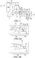
- the engine 10 can be subject to bending due to both static and dynamic loading conditions.
- a simplified engine bending scenario is show in Figures 4A, 4B and 4C .
- the engine 10 is a medium-large, geared gas turbine engine 10, having a fan diameter 112 greater than 240 cm, and more particularly greater than 300 cm.
- the engine 10 of the embodiment being described may therefore be described as a large engine, for example having a fan diameter 112 between 330 cm and 380 cm, and optionally between 335 cm and 360 cm, a gear ratio between 3.1 and 4.0, and a number of fan blades between 16 and 22.
- FIG. 4A A schematic side view of the gas turbine engine 10 is shown in Figure 4A , with the rotational axis 9 extending horizontally.
- Figure 4B shows a diagram of shear force with distance along the rotational axis 9, aligned with the schematic engine view of Figure 4A.
- Figure 4C shows a diagram of bending moment with distance along the rotational axis, aligned with the schematic engine view of Figure 4A .
- Arrow Y in Figure 4A indicates reaction load at the front mount 50 due to intake upload.
- gas turbine engines 10 are generally mounted to the wing 52 of an aircraft 90 by one or more pylons 53, as illustrated in Figures 9 and 10 .
- the pylons 53 may be secured to the engine core 11, to the nacelle 21, or to both.
- the or each pylon 53 may be secured to the engine 10 at multiple points - multiple mounts may therefore be provided for the pylon(s).
- the front mount 50 is the forward-most mount on the engine 10, and may be located on the core 11 or on the nacelle 21 in various embodiments.
- the rear mount is the rear-most mount on the engine 10, and may be located on the core 11 or on the nacelle 21 in various embodiments.
- the first flange 60a of the first flange connection 60 forms part of a first engine casing portion 10a, and is connected to a second engine casing portion 10b by a flange connector 61.
- the first flange connection 60 is provided in the second outer core casing 80.
- the second outer core casing 80 is separated into two portions at the separation point formed by the first flange connection 60.
- a first flange 60a forming the first flange connection 60 is provided on the downstream of those portions.
- An opposing second flange 60b is provided on the other portion of the second outer core casing 80 with which the first flange is coupled via the flange connector 61.
- any other suitable structure may be provided to provide a connecting point for the flange connector 61.
- the first flange radius 104 is the radial distance between the engine centre line 9 and the flange connector 61.
- the flange connector 61 comprises a plurality of bolts, and the first flange radius 104 is defined as the distance between the engine centreline 9 and a centreline of each bolt (the bolts being oriented axially and located at the same radial distance from the engine centreline 9).
- a gas path ratio is defined as: first flange radius 104 gas path radius 102
- the gas turbine engine 10 comprises a fan 23 located upstream of the engine core 11.
- the fan 23 comprises a plurality of rotor blades 23a, also referred to as fan blades 23 a, one of which is shown in Figure 5 .
- the plurality of rotor blades form a rotor blade set in an annular array around a central hub.
- the gas turbine engine is configured such that the fan diameter ratio is equal to or greater than 0.125, and more particularly less than or equal to 0.17. It may therefore be in an inclusive range between 0.125 and 0.17.
- the fan diameter ratio may have a value of 0.125, 0.130, 0.135, 0.140, 0.145, 0.150, 0.155, 0.160, 0.165 and 0.170.
- the fan diameter ratio may be, for example, between any two of the values in the previous sentence.
- the fan outlet guide vane 58 connects the engine core 11 to the nacelle 21.
- the fan OGV 58 may additionally remove or reduce the swirl from the flow coming from the fan 23.
- the axial positioning of the fan outlet guide vanes (fan OGVs) 58 may have an effect in reducing or minimising engine bending whilst maintaining flange integrity.
- the engine 10 may be designed such that the axial distance 110 between the fan OGV tip centrepoint 58b and the first flange connection 60 is relatively short.
- a ratio of the axial distance 110 between the fan OGV tip centrepoint 58b and the first flange connection 60 centre to the first flange radius 104 of 1.8 or less may provide an appropriate stiffness for the engine core 11 - this ratio may be referred to as a fan OGV tip position ratio, and may be represented as: axial distance 110 between the first flange connection 60 and the fan OGV root centrepoint 58 b first flange radius 104
- a fan OGV tip position to fan diameter ratio of: axial distance 110 between the first flange connection 60 and the fan OGV tip centrepoint 58 b the fan diameter is less than or equal to 0.22.
- the fan diameter is equal to twice the radius 101 of the fan 23.
- the fan diameter is greater than 240 cm, and more particularly greater than 300 cm (in both cases it may be no more than a maximum of 380 cm).
- the fan diameter is between 330 cm and 380 cm, and more particularly between 335 cm and 360 cm.
- the fan OGV tip position to fan diameter ratio may take a value, or fall in a range, as listed above whilst the fan OGV tip position ratio may not take a value, or fall in a range, as listed above, or vice versa. In other embodiments, both fan OGV tip position ratios may take a value, or fall in a range, as listed above.
- the pylon 53 may be connected to the core 11 in multiple places, or multiple pylons 53 may each be connected to the core 11.
- the pylon 53 may be connected to the nacelle 21 in multiple places, or multiple pylons 53 may each be connected to the nacelle 21.
- upstream and downstream are with respect to the air flow through the compressor system; and front and rear is with respect to the gas turbine engine, i.e. the fan being in the front and the turbine being in the rear of the engine.
Landscapes
- Engineering & Computer Science (AREA)
- General Engineering & Computer Science (AREA)
- Mechanical Engineering (AREA)
- Chemical & Material Sciences (AREA)
- Combustion & Propulsion (AREA)
- Aviation & Aerospace Engineering (AREA)
- Structures Of Non-Positive Displacement Pumps (AREA)
Claims (15)
- Moteur à turbine à gaz (10) pour un aéronef, le moteur à turbine à gaz (10) possédant un axe de rotation principal (9) et comprenant :une soufflante (23) située en amont du noyau de moteur (11), la soufflante comprenant une pluralité de pales de soufflante ;le noyau de moteur (11) comprenant :un système de compresseurs avec des aubes de compresseur comprenant des profils aérodynamiques respectifs, le système de compresseurs comprenant un premier compresseur à pression inférieure (14) et un second compresseur à pression supérieure (15) ; etun carter de noyau externe (76) entourant le système de compresseurs et caractérisé par :un premier raccord de bride (60) agencé pour permettre la séparation du carter de noyau externe (76) en différentes parties au niveau d'une position axiale du premier raccord de bride (60), la premier raccord de bride (60) possédant un premier rayon de bride (104) défini en tant que distance radiale entre l'axe de rotation (9) et un connecteur de bride (61) du premier raccord de bride (60), ledit premier raccord de bride (60) étant le premier raccord de bride qui est en aval d'une position axiale définie par le point médian axial entre l'emplacement axial à mi-envergure sur le bord de fuite du profil aérodynamique le plus en aval du premier compresseur (14) et l'emplacement axial à mi-envergure sur le bord d'attaque du profil aérodynamique le plus en amont du second compresseur (15) ; etun rapport de masse de pale de soufflante de :

- Moteur à turbine à gaz (10) selon la revendication 1, ledit rapport de masse de pale de soufflante étant supérieur ou égal à 11 mm/kg (5 mm/lb).
- Moteur à turbine à gaz (10) selon la revendication 1 ou la revendication 2, un rapport de masse d'ensemble de pales de :

- Moteur à turbine à gaz (10) selon une quelconque revendication précédente, chacune des pales de soufflante (23a) étant au moins partiellement formée d'un matériau métallique, éventuellement ledit matériau métallique étant du titane ou un alliage d'aluminium et de lithium ; ou chacune des pales de soufflante étant formée au moins en partiellement d'un matériau composite.
- Moteur à turbine à gaz (10) selon une quelconque revendication précédente, ledit diamètre de soufflante étant supérieur à 240 cm et inférieur ou égal à 380 cm, et éventuellement supérieur à 300 cm et inférieur ou égal à 380 cm, par exemple compris entre 330 cm et 380 cm, et éventuellement entre 335 cm et 360 cm.
- Moteur à turbine à gaz (10) selon une quelconque revendication précédente, l'un ou les deux parmi :a) ledit nombre de pales de soufflante étant compris entre 16 et 22 ; oub) ladite masse de chaque pale de soufflante étant comprise entre 9 kg (20 lb) et 32 kg (70 lb).
- Moteur à turbine à gaz (10) selon une quelconque revendication précédente, ledit moteur (10) comprenant en outre une boîte de vitesses (30) qui reçoit une entrée en provenance d'un arbre de noyau (26) et délivre en sortie un entraînement à la soufflante (23) de façon à entraîner la soufflante à une vitesse de rotation inférieure à celle de l'arbre de noyau, et éventuellement un rapport de démultiplication de la boîte de vitesses (30) étant compris entre 3,1 et 4,0.
- Moteur à turbine à gaz (10) selon une quelconque revendication précédente, ladite première bride étant au niveau, ou axialement en aval, d'un bord d'attaque du profil aérodynamique le plus en amont du second compresseur (15) ; ou ladite première bride étant au niveau, ou axialement en amont, d'un bord d'attaque du profil aérodynamique le plus en amont du second compresseur (15).
- Moteur à turbine à gaz (10) selon une quelconque revendication précédente, ledit moteur (10) comprenant :une première turbine (19), et un premier arbre de noyau (26) reliant la première turbine (19) au premier compresseur (14) ; etune seconde turbine (17) et un second arbre de noyau (27) reliant la seconde turbine au second compresseur, etladite seconde turbine, ledit second compresseur et ledit second arbre de noyau étant agencés pour tourner à une vitesse de rotation plus élevée que le premier arbre de noyau.
- Moteur à turbine à gaz (10) selon une revendication précédente, ledit noyau de moteur (11) comprenant en outre un carter de noyau interne (70) disposé radialement vers l'intérieur des aubes de compresseur du système de compresseurs (14, 15), le carter de noyau interne (70) et le carter de noyau externe (76) définissant entre eux un trajet d'écoulement de gaz de travail de noyau (A),
un rayon de trajet de gaz (102) étant défini en tant que rayon externe du trajet d'écoulement de gaz de noyau (A) au niveau de la position axiale de la première bride (60), et un rapport de trajet de gaz de :
- Moteur à turbine à gaz (10) selon une quelconque revendication précédente, un rapport de diamètre de soufflante de :

- Moteur à turbine à gaz (10) selon une quelconque revendication précédente, comprenant en outre un support avant (50, 53a) agencé pour être relié à un pylône (53), un rapport de position de support avant de :


- Moteur à turbine à gaz (10) selon la revendication 12, ledit support avant (50) étant un support de noyau.
- Moteur à turbine à gaz (10) selon une quelconque revendication précédente, comprenant en outre :une nacelle (21) entourant le noyau de moteur (11) et définissant un conduit de dérivation (22) entre le noyau de moteur (11) et la nacelle (21) ; etune aube directrice de sortie (OGV) (58) de soufflante s'étendant radialement à travers le conduit de dérivation (22) entre une surface externe du noyau de moteur (11) et la surface interne de la nacelle (21), l'OGV (58) de soufflante possédant un bord radialement interne (58a) et un bord radialement externe (58b), un point médian axial du bord radialement interne (58a) étant défini en tant que point central d'emplanture d'OGV de soufflante (58a) et un point médian axial du bord radialement externe (58b) étant défini en tant point central de pointe d'OGV de soufflante.
- Moteur à turbine à gaz (10) selon la revendication 14, l'un quelconque ou plusieurs parmi :(i) un rapport de position d'emplanture d'OGV de soufflante de :
 (ii) un rapport de position d'emplanture d'OGV de soufflante sur le diamètre de soufflante de :
 (iii) un rapport de position de pointe d'OGV de soufflante de :
 (iv) un rapport de position de pointe d'OGV de soufflante sur le diamètre de soufflante de :
Applications Claiming Priority (1)
| Application Number | Priority Date | Filing Date | Title |
|---|---|---|---|
| GBGB1906164.7A GB201906164D0 (en) | 2019-05-02 | 2019-05-02 | Gas turbine engine |
Publications (2)
| Publication Number | Publication Date |
|---|---|
| EP3734022A1 EP3734022A1 (fr) | 2020-11-04 |
| EP3734022B1 true EP3734022B1 (fr) | 2022-06-08 |
Family
ID=67385063
Family Applications (1)
| Application Number | Title | Priority Date | Filing Date |
|---|---|---|---|
| EP20170563.9A Active EP3734022B1 (fr) | 2019-05-02 | 2020-04-21 | Moteur à turbine à gaz ayant une meilleure résistance au pliage |
Country Status (4)
| Country | Link |
|---|---|
| US (5) | US10598022B1 (fr) |
| EP (1) | EP3734022B1 (fr) |
| CN (1) | CN111878254B (fr) |
| GB (1) | GB201906164D0 (fr) |
Families Citing this family (5)
| Publication number | Priority date | Publication date | Assignee | Title |
|---|---|---|---|---|
| US20150377123A1 (en) * | 2007-08-01 | 2015-12-31 | United Technologies Corporation | Turbine section of high bypass turbofan |
| FR3069291B1 (fr) * | 2017-07-24 | 2019-12-13 | Safran Aircraft Engines | Conduit d'alimentation d'un compresseur d'une turbomachine |
| US11028714B2 (en) * | 2018-07-16 | 2021-06-08 | Raytheon Technologies Corporation | Fan platform wedge seal |
| GB201906170D0 (en) | 2019-05-02 | 2019-06-19 | Rolls Royce Plc | Gas turbine engine with a double wall core casing |
| GB201906164D0 (en) * | 2019-05-02 | 2019-06-19 | Rolls Royce Plc | Gas turbine engine |
Family Cites Families (29)
| Publication number | Priority date | Publication date | Assignee | Title |
|---|---|---|---|---|
| US2747367A (en) * | 1950-03-21 | 1956-05-29 | United Aircraft Corp | Gas turbine power plant supporting structure |
| GB2044358B (en) * | 1979-03-10 | 1983-01-19 | Rolls Royce | Gas turbine jet engine mounting |
| WO1992019854A1 (fr) | 1991-05-08 | 1992-11-12 | United Technologies Corporation | Montant de ventilateur demontable pour groupe motopropulseur d'un turboreacteur a double flux a gaz |
| US6467988B1 (en) | 2000-05-20 | 2002-10-22 | General Electric Company | Reducing cracking adjacent shell flange connecting bolts |
| ITTO20010444A1 (it) | 2001-05-11 | 2002-11-11 | Fiatavio Spa | Turbina assiale per applicazioni aeronautiche. |
| EP1783330A3 (fr) | 2003-07-29 | 2011-03-09 | Pratt & Whitney Canada Corp. | Carter de turboréacteur à double flux |
| US7476086B2 (en) | 2005-04-07 | 2009-01-13 | General Electric Company | Tip cambered swept blade |
| EP2181262B1 (fr) * | 2007-08-08 | 2012-05-16 | Rohr, Inc. | Buse de ventilateur à surface variable avec écoulement de dérivation |
| FR2925121B1 (fr) | 2007-12-18 | 2014-07-04 | Snecma | Carter intermediaire pour turboreacteur d'aeronef a conception amelioree |
| FR2931906B1 (fr) | 2008-05-30 | 2017-06-02 | Snecma | Compresseur de turbomachine avec un systeme d'injection d'air. |
| US8347500B2 (en) | 2008-11-28 | 2013-01-08 | Pratt & Whitney Canada Corp. | Method of assembly and disassembly of a gas turbine mid turbine frame |
| GB0904970D0 (en) * | 2009-03-24 | 2009-05-06 | Rolls Royce Plc | A casing arrangement |
| EP2427634B1 (fr) | 2009-05-07 | 2018-04-11 | GKN Aerospace Sweden AB | Support et structure de turbine à gaz comprenant ledit support |
| US8313293B2 (en) * | 2009-05-15 | 2012-11-20 | Pratt & Whitney Canada Corp. | Turbofan mounting system |
| US8328508B2 (en) | 2009-09-22 | 2012-12-11 | Honeywell International Inc. | Cooling systems and assemblies for cooling an aft bearing assembly mounted to a rotor |
| US9004849B2 (en) | 2012-01-10 | 2015-04-14 | United Technologies Corporation | Gas turbine engine forward bearing compartment architecture |
| US9353754B2 (en) | 2012-03-13 | 2016-05-31 | Embry-Riddle Aeronautical University, Inc. | Multi-stage axial compressor with counter-rotation using accessory drive |
| US20150247461A1 (en) * | 2012-10-01 | 2015-09-03 | United Technologies Corporation | Geared turbofan with high fan rotor power intensity |
| US9970323B2 (en) | 2012-10-09 | 2018-05-15 | United Technologies Corporation | Geared turbofan engine with optimized diffuser case flange location |
| US10724479B2 (en) * | 2013-03-15 | 2020-07-28 | United Technologies Corporation | Thrust efficient turbofan engine |
| JP6472362B2 (ja) | 2015-10-05 | 2019-02-20 | 三菱重工航空エンジン株式会社 | ガスタービン用ケーシング及びガスタービン |
| US10723471B2 (en) * | 2017-06-14 | 2020-07-28 | General Electric Company | Method and system for mounting an aircraft engine |
| GB2566047B (en) * | 2017-08-31 | 2019-12-11 | Rolls Royce Plc | Gas turbine engine |
| GB2566045B (en) | 2017-08-31 | 2019-12-11 | Rolls Royce Plc | Gas turbine engine |
| GB201810606D0 (en) * | 2018-06-28 | 2018-08-15 | Rolls Royce Plc | Gas turbine engine |
| GB201812553D0 (en) * | 2018-08-01 | 2018-09-12 | Rolls Royce Plc | Gas turbine engine |
| GB201820918D0 (en) * | 2018-12-21 | 2019-02-06 | Rolls Royce Plc | Turbine engine |
| GB201903261D0 (en) * | 2019-03-11 | 2019-04-24 | Rolls Royce Plc | Efficient gas turbine engine installation and operation |
| GB201906164D0 (en) * | 2019-05-02 | 2019-06-19 | Rolls Royce Plc | Gas turbine engine |
-
2019
- 2019-05-02 GB GBGB1906164.7A patent/GB201906164D0/en not_active Ceased
- 2019-06-25 US US16/451,467 patent/US10598022B1/en active Active
-
2020
- 2020-01-31 US US16/778,795 patent/US11008870B2/en active Active
- 2020-01-31 US US16/778,617 patent/US10858942B2/en active Active
- 2020-04-21 EP EP20170563.9A patent/EP3734022B1/fr active Active
- 2020-04-28 CN CN202010350226.XA patent/CN111878254B/zh active Active
- 2020-10-28 US US17/082,886 patent/US11111791B2/en active Active
-
2021
- 2021-07-21 US US17/381,767 patent/US11333021B2/en active Active
Also Published As
| Publication number | Publication date |
|---|---|
| US20200347731A1 (en) | 2020-11-05 |
| US10598022B1 (en) | 2020-03-24 |
| US11333021B2 (en) | 2022-05-17 |
| GB201906164D0 (en) | 2019-06-19 |
| US11008870B2 (en) | 2021-05-18 |
| US20200347730A1 (en) | 2020-11-05 |
| US10858942B2 (en) | 2020-12-08 |
| CN111878254B (zh) | 2023-04-25 |
| US20210115797A1 (en) | 2021-04-22 |
| US20220098984A1 (en) | 2022-03-31 |
| US11111791B2 (en) | 2021-09-07 |
| CN111878254A (zh) | 2020-11-03 |
| EP3734022A1 (fr) | 2020-11-04 |
Similar Documents
| Publication | Publication Date | Title |
|---|---|---|
| EP3734022B1 (fr) | Moteur à turbine à gaz ayant une meilleure résistance au pliage | |
| EP3553303A1 (fr) | Moteur à turbine à gaz et agencement de turbine | |
| US11268440B2 (en) | Stabilization bearing system for geared turbofan engines | |
| US20240093610A1 (en) | Super-cooled ice impact protection for a gas turbine engine | |
| EP3683431B1 (fr) | Conduit d'entrée hautement chargé dans un turboréacteur à engrenages | |
| EP3734016B1 (fr) | Moteur à turbine à gaz comportant aubes directrices de sortie de soufflante | |
| EP3667022A1 (fr) | Protection contre les cristaux de glace pour un turboréacteur | |
| EP3734024B1 (fr) | Moteur à turbine à gaz ayant une meilleure résistance au pliage | |
| EP3734023B1 (fr) | Moteur à turbine à gaz ayant une meilleure résistance au pliage | |
| EP3734044A1 (fr) | Moteur à turbine à gaz comportant un support de noyau | |
| US11118470B2 (en) | Gas turbine engine with a double wall core casing | |
| US11834958B2 (en) | Rotor assembly | |
| EP3546367B1 (fr) | Agencement de montage de moteur à double flux à engrenage | |
| EP3741982A1 (fr) | Moteur de turbine à gaz | |
| EP3712393A1 (fr) | Structure de support de palier de moteur de turbine à gaz |
Legal Events
| Date | Code | Title | Description |
|---|---|---|---|
| PUAI | Public reference made under article 153(3) epc to a published international application that has entered the european phase |
Free format text: ORIGINAL CODE: 0009012 |
|
| STAA | Information on the status of an ep patent application or granted ep patent |
Free format text: STATUS: THE APPLICATION HAS BEEN PUBLISHED |
|
| AK | Designated contracting states |
Kind code of ref document: A1 Designated state(s): AL AT BE BG CH CY CZ DE DK EE ES FI FR GB GR HR HU IE IS IT LI LT LU LV MC MK MT NL NO PL PT RO RS SE SI SK SM TR |
|
| AX | Request for extension of the european patent |
Extension state: BA ME |
|
| STAA | Information on the status of an ep patent application or granted ep patent |
Free format text: STATUS: REQUEST FOR EXAMINATION WAS MADE |
|
| 17P | Request for examination filed |
Effective date: 20210429 |
|
| RBV | Designated contracting states (corrected) |
Designated state(s): AL AT BE BG CH CY CZ DE DK EE ES FI FR GB GR HR HU IE IS IT LI LT LU LV MC MK MT NL NO PL PT RO RS SE SI SK SM TR |
|
| GRAP | Despatch of communication of intention to grant a patent |
Free format text: ORIGINAL CODE: EPIDOSNIGR1 |
|
| STAA | Information on the status of an ep patent application or granted ep patent |
Free format text: STATUS: GRANT OF PATENT IS INTENDED |
|
| INTG | Intention to grant announced |
Effective date: 20220317 |
|
| GRAS | Grant fee paid |
Free format text: ORIGINAL CODE: EPIDOSNIGR3 |
|
| GRAA | (expected) grant |
Free format text: ORIGINAL CODE: 0009210 |
|
| STAA | Information on the status of an ep patent application or granted ep patent |
Free format text: STATUS: THE PATENT HAS BEEN GRANTED |
|
| AK | Designated contracting states |
Kind code of ref document: B1 Designated state(s): AL AT BE BG CH CY CZ DE DK EE ES FI FR GB GR HR HU IE IS IT LI LT LU LV MC MK MT NL NO PL PT RO RS SE SI SK SM TR |
|
| REG | Reference to a national code |
Ref country code: AT Ref legal event code: REF Ref document number: 1497055 Country of ref document: AT Kind code of ref document: T Effective date: 20220615 Ref country code: CH Ref legal event code: EP |
|
| REG | Reference to a national code |
Ref country code: DE Ref legal event code: R096 Ref document number: 602020003432 Country of ref document: DE |
|
| REG | Reference to a national code |
Ref country code: IE Ref legal event code: FG4D |
|
| REG | Reference to a national code |
Ref country code: LT Ref legal event code: MG9D |
|
| REG | Reference to a national code |
Ref country code: NL Ref legal event code: MP Effective date: 20220608 |
|
| PG25 | Lapsed in a contracting state [announced via postgrant information from national office to epo] |
Ref country code: SE Free format text: LAPSE BECAUSE OF FAILURE TO SUBMIT A TRANSLATION OF THE DESCRIPTION OR TO PAY THE FEE WITHIN THE PRESCRIBED TIME-LIMIT Effective date: 20220608 Ref country code: NO Free format text: LAPSE BECAUSE OF FAILURE TO SUBMIT A TRANSLATION OF THE DESCRIPTION OR TO PAY THE FEE WITHIN THE PRESCRIBED TIME-LIMIT Effective date: 20220908 Ref country code: LT Free format text: LAPSE BECAUSE OF FAILURE TO SUBMIT A TRANSLATION OF THE DESCRIPTION OR TO PAY THE FEE WITHIN THE PRESCRIBED TIME-LIMIT Effective date: 20220608 Ref country code: HR Free format text: LAPSE BECAUSE OF FAILURE TO SUBMIT A TRANSLATION OF THE DESCRIPTION OR TO PAY THE FEE WITHIN THE PRESCRIBED TIME-LIMIT Effective date: 20220608 Ref country code: GR Free format text: LAPSE BECAUSE OF FAILURE TO SUBMIT A TRANSLATION OF THE DESCRIPTION OR TO PAY THE FEE WITHIN THE PRESCRIBED TIME-LIMIT Effective date: 20220909 Ref country code: FI Free format text: LAPSE BECAUSE OF FAILURE TO SUBMIT A TRANSLATION OF THE DESCRIPTION OR TO PAY THE FEE WITHIN THE PRESCRIBED TIME-LIMIT Effective date: 20220608 Ref country code: BG Free format text: LAPSE BECAUSE OF FAILURE TO SUBMIT A TRANSLATION OF THE DESCRIPTION OR TO PAY THE FEE WITHIN THE PRESCRIBED TIME-LIMIT Effective date: 20220908 |
|
| REG | Reference to a national code |
Ref country code: AT Ref legal event code: MK05 Ref document number: 1497055 Country of ref document: AT Kind code of ref document: T Effective date: 20220608 |
|
| PG25 | Lapsed in a contracting state [announced via postgrant information from national office to epo] |
Ref country code: RS Free format text: LAPSE BECAUSE OF FAILURE TO SUBMIT A TRANSLATION OF THE DESCRIPTION OR TO PAY THE FEE WITHIN THE PRESCRIBED TIME-LIMIT Effective date: 20220608 Ref country code: LV Free format text: LAPSE BECAUSE OF FAILURE TO SUBMIT A TRANSLATION OF THE DESCRIPTION OR TO PAY THE FEE WITHIN THE PRESCRIBED TIME-LIMIT Effective date: 20220608 |
|
| PG25 | Lapsed in a contracting state [announced via postgrant information from national office to epo] |
Ref country code: NL Free format text: LAPSE BECAUSE OF FAILURE TO SUBMIT A TRANSLATION OF THE DESCRIPTION OR TO PAY THE FEE WITHIN THE PRESCRIBED TIME-LIMIT Effective date: 20220608 |
|
| PG25 | Lapsed in a contracting state [announced via postgrant information from national office to epo] |
Ref country code: SM Free format text: LAPSE BECAUSE OF FAILURE TO SUBMIT A TRANSLATION OF THE DESCRIPTION OR TO PAY THE FEE WITHIN THE PRESCRIBED TIME-LIMIT Effective date: 20220608 Ref country code: SK Free format text: LAPSE BECAUSE OF FAILURE TO SUBMIT A TRANSLATION OF THE DESCRIPTION OR TO PAY THE FEE WITHIN THE PRESCRIBED TIME-LIMIT Effective date: 20220608 Ref country code: RO Free format text: LAPSE BECAUSE OF FAILURE TO SUBMIT A TRANSLATION OF THE DESCRIPTION OR TO PAY THE FEE WITHIN THE PRESCRIBED TIME-LIMIT Effective date: 20220608 Ref country code: PT Free format text: LAPSE BECAUSE OF FAILURE TO SUBMIT A TRANSLATION OF THE DESCRIPTION OR TO PAY THE FEE WITHIN THE PRESCRIBED TIME-LIMIT Effective date: 20221010 Ref country code: ES Free format text: LAPSE BECAUSE OF FAILURE TO SUBMIT A TRANSLATION OF THE DESCRIPTION OR TO PAY THE FEE WITHIN THE PRESCRIBED TIME-LIMIT Effective date: 20220608 Ref country code: EE Free format text: LAPSE BECAUSE OF FAILURE TO SUBMIT A TRANSLATION OF THE DESCRIPTION OR TO PAY THE FEE WITHIN THE PRESCRIBED TIME-LIMIT Effective date: 20220608 Ref country code: CZ Free format text: LAPSE BECAUSE OF FAILURE TO SUBMIT A TRANSLATION OF THE DESCRIPTION OR TO PAY THE FEE WITHIN THE PRESCRIBED TIME-LIMIT Effective date: 20220608 Ref country code: AT Free format text: LAPSE BECAUSE OF FAILURE TO SUBMIT A TRANSLATION OF THE DESCRIPTION OR TO PAY THE FEE WITHIN THE PRESCRIBED TIME-LIMIT Effective date: 20220608 |
|
| PG25 | Lapsed in a contracting state [announced via postgrant information from national office to epo] |
Ref country code: PL Free format text: LAPSE BECAUSE OF FAILURE TO SUBMIT A TRANSLATION OF THE DESCRIPTION OR TO PAY THE FEE WITHIN THE PRESCRIBED TIME-LIMIT Effective date: 20220608 Ref country code: IS Free format text: LAPSE BECAUSE OF FAILURE TO SUBMIT A TRANSLATION OF THE DESCRIPTION OR TO PAY THE FEE WITHIN THE PRESCRIBED TIME-LIMIT Effective date: 20221008 |
|
| REG | Reference to a national code |
Ref country code: DE Ref legal event code: R097 Ref document number: 602020003432 Country of ref document: DE |
|
| PG25 | Lapsed in a contracting state [announced via postgrant information from national office to epo] |
Ref country code: AL Free format text: LAPSE BECAUSE OF FAILURE TO SUBMIT A TRANSLATION OF THE DESCRIPTION OR TO PAY THE FEE WITHIN THE PRESCRIBED TIME-LIMIT Effective date: 20220608 |
|
| PLBE | No opposition filed within time limit |
Free format text: ORIGINAL CODE: 0009261 |
|
| STAA | Information on the status of an ep patent application or granted ep patent |
Free format text: STATUS: NO OPPOSITION FILED WITHIN TIME LIMIT |
|
| PG25 | Lapsed in a contracting state [announced via postgrant information from national office to epo] |
Ref country code: DK Free format text: LAPSE BECAUSE OF FAILURE TO SUBMIT A TRANSLATION OF THE DESCRIPTION OR TO PAY THE FEE WITHIN THE PRESCRIBED TIME-LIMIT Effective date: 20220608 |
|
| 26N | No opposition filed |
Effective date: 20230310 |
|
| PG25 | Lapsed in a contracting state [announced via postgrant information from national office to epo] |
Ref country code: SI Free format text: LAPSE BECAUSE OF FAILURE TO SUBMIT A TRANSLATION OF THE DESCRIPTION OR TO PAY THE FEE WITHIN THE PRESCRIBED TIME-LIMIT Effective date: 20220608 |
|
| P01 | Opt-out of the competence of the unified patent court (upc) registered |
Effective date: 20230528 |
|
| PGFP | Annual fee paid to national office [announced via postgrant information from national office to epo] |
Ref country code: FR Payment date: 20230421 Year of fee payment: 4 Ref country code: DE Payment date: 20230427 Year of fee payment: 4 |
|
| REG | Reference to a national code |
Ref country code: CH Ref legal event code: PL |
|
| PG25 | Lapsed in a contracting state [announced via postgrant information from national office to epo] |
Ref country code: LU Free format text: LAPSE BECAUSE OF NON-PAYMENT OF DUE FEES Effective date: 20230421 |
|
| REG | Reference to a national code |
Ref country code: BE Ref legal event code: MM Effective date: 20230430 |
|
| PG25 | Lapsed in a contracting state [announced via postgrant information from national office to epo] |
Ref country code: MC Free format text: LAPSE BECAUSE OF FAILURE TO SUBMIT A TRANSLATION OF THE DESCRIPTION OR TO PAY THE FEE WITHIN THE PRESCRIBED TIME-LIMIT Effective date: 20220608 |
|
| PG25 | Lapsed in a contracting state [announced via postgrant information from national office to epo] |
Ref country code: MC Free format text: LAPSE BECAUSE OF FAILURE TO SUBMIT A TRANSLATION OF THE DESCRIPTION OR TO PAY THE FEE WITHIN THE PRESCRIBED TIME-LIMIT Effective date: 20220608 Ref country code: LI Free format text: LAPSE BECAUSE OF NON-PAYMENT OF DUE FEES Effective date: 20230430 Ref country code: IT Free format text: LAPSE BECAUSE OF FAILURE TO SUBMIT A TRANSLATION OF THE DESCRIPTION OR TO PAY THE FEE WITHIN THE PRESCRIBED TIME-LIMIT Effective date: 20220608 Ref country code: CH Free format text: LAPSE BECAUSE OF NON-PAYMENT OF DUE FEES Effective date: 20230430 |
|
| REG | Reference to a national code |
Ref country code: IE Ref legal event code: MM4A |
|
| PG25 | Lapsed in a contracting state [announced via postgrant information from national office to epo] |
Ref country code: BE Free format text: LAPSE BECAUSE OF NON-PAYMENT OF DUE FEES Effective date: 20230430 |
|
| PG25 | Lapsed in a contracting state [announced via postgrant information from national office to epo] |
Ref country code: IE Free format text: LAPSE BECAUSE OF NON-PAYMENT OF DUE FEES Effective date: 20230421 |
|
| PG25 | Lapsed in a contracting state [announced via postgrant information from national office to epo] |
Ref country code: IE Free format text: LAPSE BECAUSE OF NON-PAYMENT OF DUE FEES Effective date: 20230421 |