EP3733954A1 - User-interface system for a laundry appliance - Google Patents
User-interface system for a laundry appliance Download PDFInfo
- Publication number
- EP3733954A1 EP3733954A1 EP20168589.8A EP20168589A EP3733954A1 EP 3733954 A1 EP3733954 A1 EP 3733954A1 EP 20168589 A EP20168589 A EP 20168589A EP 3733954 A1 EP3733954 A1 EP 3733954A1
- Authority
- EP
- European Patent Office
- Prior art keywords
- door
- microphone
- assembly
- coupled
- locating
- Prior art date
- Legal status (The legal status is an assumption and is not a legal conclusion. Google has not performed a legal analysis and makes no representation as to the accuracy of the status listed.)
- Granted
Links
Images




Classifications
-
- D—TEXTILES; PAPER
- D06—TREATMENT OF TEXTILES OR THE LIKE; LAUNDERING; FLEXIBLE MATERIALS NOT OTHERWISE PROVIDED FOR
- D06F—LAUNDERING, DRYING, IRONING, PRESSING OR FOLDING TEXTILE ARTICLES
- D06F34/00—Details of control systems for washing machines, washer-dryers or laundry dryers
- D06F34/28—Arrangements for program selection, e.g. control panels therefor; Arrangements for indicating program parameters, e.g. the selected program or its progress
- D06F34/34—Arrangements for program selection, e.g. control panels therefor; Arrangements for indicating program parameters, e.g. the selected program or its progress characterised by mounting or attachment features, e.g. detachable control panels or detachable display panels
-
- D—TEXTILES; PAPER
- D06—TREATMENT OF TEXTILES OR THE LIKE; LAUNDERING; FLEXIBLE MATERIALS NOT OTHERWISE PROVIDED FOR
- D06F—LAUNDERING, DRYING, IRONING, PRESSING OR FOLDING TEXTILE ARTICLES
- D06F34/00—Details of control systems for washing machines, washer-dryers or laundry dryers
- D06F34/28—Arrangements for program selection, e.g. control panels therefor; Arrangements for indicating program parameters, e.g. the selected program or its progress
-
- D—TEXTILES; PAPER
- D06—TREATMENT OF TEXTILES OR THE LIKE; LAUNDERING; FLEXIBLE MATERIALS NOT OTHERWISE PROVIDED FOR
- D06F—LAUNDERING, DRYING, IRONING, PRESSING OR FOLDING TEXTILE ARTICLES
- D06F39/00—Details of washing machines not specific to a single type of machines covered by groups D06F9/00 - D06F27/00
- D06F39/12—Casings; Tubs
- D06F39/14—Doors or covers; Securing means therefor
-
- D—TEXTILES; PAPER
- D06—TREATMENT OF TEXTILES OR THE LIKE; LAUNDERING; FLEXIBLE MATERIALS NOT OTHERWISE PROVIDED FOR
- D06F—LAUNDERING, DRYING, IRONING, PRESSING OR FOLDING TEXTILE ARTICLES
- D06F34/00—Details of control systems for washing machines, washer-dryers or laundry dryers
- D06F34/28—Arrangements for program selection, e.g. control panels therefor; Arrangements for indicating program parameters, e.g. the selected program or its progress
- D06F34/32—Arrangements for program selection, e.g. control panels therefor; Arrangements for indicating program parameters, e.g. the selected program or its progress characterised by graphical features, e.g. touchscreens
-
- G—PHYSICS
- G06—COMPUTING OR CALCULATING; COUNTING
- G06F—ELECTRIC DIGITAL DATA PROCESSING
- G06F3/00—Input arrangements for transferring data to be processed into a form capable of being handled by the computer; Output arrangements for transferring data from processing unit to output unit, e.g. interface arrangements
- G06F3/16—Sound input; Sound output
- G06F3/162—Interface to dedicated audio devices, e.g. audio drivers, interface to CODECs
-
- G—PHYSICS
- G10—MUSICAL INSTRUMENTS; ACOUSTICS
- G10L—SPEECH ANALYSIS TECHNIQUES OR SPEECH SYNTHESIS; SPEECH RECOGNITION; SPEECH OR VOICE PROCESSING TECHNIQUES; SPEECH OR AUDIO CODING OR DECODING
- G10L15/00—Speech recognition
- G10L15/22—Procedures used during a speech recognition process, e.g. man-machine dialogue
-
- H—ELECTRICITY
- H04—ELECTRIC COMMUNICATION TECHNIQUE
- H04R—LOUDSPEAKERS, MICROPHONES, GRAMOPHONE PICK-UPS OR LIKE ACOUSTIC ELECTROMECHANICAL TRANSDUCERS; ELECTRIC HEARING AIDS; PUBLIC ADDRESS SYSTEMS
- H04R1/00—Details of transducers, loudspeakers or microphones
- H04R1/02—Casings; Cabinets ; Supports therefor; Mountings therein
- H04R1/04—Structural association of microphone with electric circuitry therefor
-
- H—ELECTRICITY
- H04—ELECTRIC COMMUNICATION TECHNIQUE
- H04R—LOUDSPEAKERS, MICROPHONES, GRAMOPHONE PICK-UPS OR LIKE ACOUSTIC ELECTROMECHANICAL TRANSDUCERS; ELECTRIC HEARING AIDS; PUBLIC ADDRESS SYSTEMS
- H04R1/00—Details of transducers, loudspeakers or microphones
- H04R1/08—Mouthpieces; Microphones; Attachments therefor
-
- D—TEXTILES; PAPER
- D06—TREATMENT OF TEXTILES OR THE LIKE; LAUNDERING; FLEXIBLE MATERIALS NOT OTHERWISE PROVIDED FOR
- D06F—LAUNDERING, DRYING, IRONING, PRESSING OR FOLDING TEXTILE ARTICLES
- D06F2105/00—Systems or parameters controlled or affected by the control systems of washing machines, washer-dryers or laundry dryers
- D06F2105/58—Indications or alarms to the control system or to the user
-
- D—TEXTILES; PAPER
- D06—TREATMENT OF TEXTILES OR THE LIKE; LAUNDERING; FLEXIBLE MATERIALS NOT OTHERWISE PROVIDED FOR
- D06F—LAUNDERING, DRYING, IRONING, PRESSING OR FOLDING TEXTILE ARTICLES
- D06F34/00—Details of control systems for washing machines, washer-dryers or laundry dryers
- D06F34/08—Control circuits or arrangements thereof
-
- G—PHYSICS
- G10—MUSICAL INSTRUMENTS; ACOUSTICS
- G10L—SPEECH ANALYSIS TECHNIQUES OR SPEECH SYNTHESIS; SPEECH RECOGNITION; SPEECH OR VOICE PROCESSING TECHNIQUES; SPEECH OR AUDIO CODING OR DECODING
- G10L15/00—Speech recognition
- G10L15/22—Procedures used during a speech recognition process, e.g. man-machine dialogue
- G10L2015/223—Execution procedure of a spoken command
Definitions
- the present disclosure generally relates to a user-interface system, and more specifically, to a user-interface system for a laundry appliance.
- Laundry appliances typically include a user-interface for a user to enter commands to control the laundry appliance.
- the user-interface may include a microphone, which allows the user to control the laundry appliance via voice commands.
- user-interfaces may include a visual indicator, such as a display screen.
- a laundry appliance includes a cabinet.
- a door is coupled to the cabinet. The door is operable between a closed position and an opened position.
- a microphone assembly is coupled to the door. The microphone assembly is configured to receive a voice command.
- a microcontroller is coupled to the door. The microcontroller is operably coupled to the microphone assembly.
- a proximity sensor is coupled to the microphone assembly and the microcontroller. The proximity sensor defines a sensor field that extends outward from the door.
- an appliance door includes a door panel that has an outer surface and an inner surface.
- the door panel defines an elongated channel that is configured as a handle.
- An audio interface is disposed proximate the handle.
- the audio interface includes a speaker and a microphone printed circuit board assembly that has at least one microphone.
- a visual interface is coupled to the inner surface of the door. The visual interface is configured to display messages on the outer surface of the door.
- a door assembly includes a door panel that forms a handle.
- a printed circuit board is coupled to the door panel proximate the handle.
- a plurality of microphones is coupled to a printed circuit board.
- An acoustic layer is coupled to the printed circuit board. Each microphone aligns with a microphone port aperture that is defined by the acoustic layer.
- a cover member is disposed at least partially within the handle. The cover member is disposed adjacent to the acoustic layer.
- the present illustrated embodiments reside primarily in combinations of method steps and apparatus components related to a microphone assembly for a laundry appliance. Accordingly, the apparatus components and method steps have been represented, where appropriate, by conventional symbols in the drawings, showing only those specific details that are pertinent to understanding the embodiments of the present disclosure so as not to obscure the disclosure with details that will be readily apparent to those of ordinary skill in the art having the benefit of the description herein. Further, like numerals in the description and drawings represent like elements.
- the terms “upper,” “lower,” “right,” “left,” “rear,” “front,” “vertical,” “horizontal,” and derivatives thereof shall relate to the disclosure as oriented in FIG. 1 .
- the term “front” shall refer to the surface of the element closer to an intended viewer, and the term “rear” shall refer to the surface of the element further from the intended viewer.
- the disclosure may assume various alternative orientations, except where expressly specified to the contrary.
- the specific devices and processes illustrated in the attached drawings, and described in the following specification are simply exemplary embodiments of the inventive concepts defined in the appended claims. Hence, specific dimensions and other physical characteristics relating to the embodiments disclosed herein are not to be considered as limiting, unless the claims expressly state otherwise.
- reference numeral 10 generally designates a laundry appliance including a cabinet 14 and a door 18 rotatably coupled to the cabinet 14.
- a user-interface system 22 is coupled to the door 18 and includes a visual interface 26 defining a light ring 30 and an audio interface 34.
- the audio interface 34 includes a microphone assembly 38.
- the user-interface system 22 includes a microcontroller 42 operably coupled to the visual and audio interfaces 26, 34.
- the laundry appliance 10 includes the cabinet 14 having a front surface 46 and a door 18 rotatably coupled to the cabinet 14.
- the door 18 may be a flat panel door, a fishbowl-style door, and/or a combination thereof.
- the laundry appliance 10 is a front-load, horizontal axis laundry appliance 10.
- the laundry appliance 10 may be a washer, dryer, and/or a combination thereof.
- the laundry appliance 10 can be a top-load laundry appliance 10 or another configuration of a front-load laundry appliance 10.
- the door 18 is operable between opened and closed positions.
- the door 18 opens in a side-to-side manner, however, it is contemplated that the door 18 can open in an up-and-down manner.
- the door 18 is configured to allow access to a drum 50 positioned within the cabinet 14 when in an opened position, and encloses the drum 50 when in the closed position.
- a top edge 54 of the door 18 is substantially coplanar with a top surface 58 of the cabinet 14.
- a decorative panel may also be placed over the top surface 58 of the cabinet 14 and the top edge 54 of the door 187.
- a bottom edge 62 of the door 18 is spaced-apart from a bottom surface 66 of the cabinet 14.
- the bottom edge 62 of the door 18 can be coplanar with the bottom surface 66 of the cabinet 14.
- the door 18 (e.g., a door panel) has a substantially rectangular shape.
- the shape of the door 18 substantially aligns with the shape of the cabinet 14.
- the door 18 and the front surface 46 of the cabinet 14 have substantially similar shapes.
- the door 18 and the front surface 46 of the cabinet 14 may have different shapes.
- the door 18 can have a substantially circular or oblong shape.
- a rear surface of the door 18 defines and/or includes a deflector 70.
- the door 18 typically includes the deflector 70.
- the deflector 70 extends into the drum 50 via an opening 74 in the front surface 46 of the cabinet 14.
- the deflector 70 is advantageous for deflecting laundry away from the door 18 or a bellows assembly 78, which is positioned about the perimeter of the opening 74 of the cabinet 14.
- the door 18 may be included on other appliances, such as, for example, a dishwasher, an oven, a refrigerating appliance, a countertop appliance, etc.
- the door 18 includes a handle 82 adjacent to the top edge 54 of the door 18. It is contemplated that the handle 82 may be located in other locations on the door 18, such as, for example, proximate to a left or a right side edge 86, 90 of the door 18.
- An outer surface 94 of a rear panel of the door 18 partially defines an elongated cavity or channel 98 proximate the handle 82, which is typically positioned adjacent to the top edge 54 of the door 18.
- the door 18 can provide for a variety of configurations of the elongated channel 98. For example, the elongated channel 98 often extends between the left side edge 86 to the right side edge 90 of the door 18.
- the elongated channel 98 extends the entire distance between the left and right side edges 86, 90. It is further contemplated that the elongated channel 98 may extend in a different direction along the door 18, such as, for example, between the top edge 54 and the bottom edge 62 of the door 18.
- the microphone assembly 38 and at least one speaker 102 are coupled to the door 18 proximate the handle 82 and are in auditory communication with the handle 82.
- the laundry appliance 10 includes two speakers 102.
- One speaker 102 is positioned adjacent to the left side edge 86 and the other speaker 102 is positioned adjacent to the right side edge 90 of the door 18 within the elongated channel 98.
- the configuration of the microphone assembly 38 and the speakers 102 can depend on a variety of factors. More orfewer speakers 102 may be included without departing from the teachings herein.
- the microphone assembly 38 is disposed proximate the handle 82 and is disposed between speakers 102.
- a cover member 106 at least partially defines the elongated channel 98.
- the elongated channel 98 is defined between the cover member 106 and the door 18.
- the cover member 106 defines speaker apertures 110 for an audio output to be communicated to a user.
- the cover member 106 additionally defines microphone apertures 114 for an input (e.g., a voice command) to be communicated from a user to the microphone assembly 38.
- the cover member 106 can have a variety of configurations based on a number of factors, including, for example, the configuration of the microphone assembly 38 and the speakers 102. For example, as illustrated in FIGS. 3 and 4 , the cover member 106 defines four microphone apertures 114A-114D, collectively referred to as the microphone apertures 114. However, the number of microphone apertures 114 may be greater or fewer based on the configuration of the microphone assembly 38. Additionally, the cover member 106 defines a sensor aperture 118 disposed among the microphone apertures 114 and typically between the microphone apertures 114B, 114C. The sensor aperture 118 may be the same size or a different size than the microphone apertures 114. Each of the speaker apertures 110, the microphone apertures 114, and the sensor aperture 118 may be a single aperture or a plurality of apertures without departing from the teachings herein.
- the door 18 includes a channel interior surface 122 defining a pocket 126.
- the pocket 126 is typically molded into the door 18, such that the pocket 126 is integrally formed with the door 18.
- Other configurations are also contemplated based on the configuration of the microphone assembly 38.
- the pocket 126 can be offset from the channel interior surface 122 by a raised border 130 or can extend into the channel interior surface 122 forming a recessed portion.
- the raised border 130 extends outward (e.g., forward) from the channel interior surface 122 and typically surrounds the pocket 126.
- a rear pocket surface 134 may be substantially coplanar with the channel interior surface 122.
- the rear pocket surface 134 may be setback from the channel interior surface 122.
- the pocket 126 has a substantially rectangular shape, however, it is contemplated that the pocket 126 may be any shape based on the configuration of the microphone assembly 38.
- the rear pocket surface 134 defines locating protrusions 138 extending outward towards a front 142 of the laundry appliance 10.
- the specific configuration may vary based on the configuration of the microphone assembly 38 and/or the laundry appliance 10.
- the pocket 126 includes two locating protrusions 138.
- more or fewer locating protrusions 138 may be included without departing from the teachings herein.
- the number of locating protrusions 138 is often based on the size and/or shape of the microphone assembly 38 and/or the door 18.
- the locating protrusions 138 may be substantially cylindrical or frusto-conical or any other practicable shape.
- the locating protrusions 138 are illustrated in FIG. 4 as extending a substantially same distance from the rear pocket surface 134. Alternatively, the locating protrusions 138 may extend different distances from the rear pocket surface 134.
- the configuration may depend on the configuration of the mating components.
- the locating protrusions 138 are positioned substantially the same distance from opposing lateral sides of the pocket 126, respectively. Additionally, the locating protrusions 138 are positioned along a horizontal midpoint of the pocket 126. In other words, the locating protrusions 138 are positioned substantially equidistant from upper and lower sides of the pocket 126.
- These configurations and locations of the protrusions 138 are contemplated. Accordingly, the positioning of the locating protrusion 138 is generally dependent on the location of corresponding locating channels 160 defined in a locating gasket 162 of the microphone assembly 38 that are configured to receive the locating protrusions 138.
- the locations of the locating protrusion 138 and the locating channels 160 can vary depending on the design of the device and locations of various components.
- the audio interface 34 of the laundry appliance 10 includes the microphone assembly 38 for receiving a user input via voice commands and the speaker 102 ( FIG. 1 ) for projecting an audio output to the user.
- the microphone assembly 38 includes the locating gasket 162 and a microphone printed circuit board (MPCB) assembly 166 including at least one microphone 206.
- the MPCB assembly 166 is coupled to the locating gasket 162.
- the microphone assembly 38 includes an acoustic layer 170 coupled to the MPCB assembly 166 on an opposing side relative to the locating gasket 162.
- the locating gasket 162 is configured to be positioned within the pocket 126 of the handle 82 defined by the channel interior surface 122 when the handle 82 is assembled.
- the locating gasket 162 can have a variety of configurations.
- the locating gasket 162, as illustrated in FIG. 4 has a substantially rectangular shape.
- the locating gasket 162 may have any shape that substantially corresponds with the shape of the pocket 126 to produce a form-fitting connection.
- the configuration of the locating gasket 162 can vary based on the configuration of the device. For example, outer surfaces 174 of the locating gasket 162 abut the raised border 130 that defines the pocket 126.
- the border can be continuous or can include interruptions and gaps in the structure that surrounds and defines the pocket 126.
- the outer surfaces 174 of the locating gasket 162 can directly abut the channel interior surface 122 that defines the pocket 126.
- the locating gasket 162 is configured to substantially fill the pocket 126. In such examples, there is typically not a gap between the locating gasket 162 and the rear pocket surface 134. Accordingly, the pocket 126 and the locating gasket 162 may have substantially similar depths. However, it is contemplated that the locating gasket 162 may have a greater depth compared to the pocket 126 to engage the cover member 106 without departing from the teachings herein.
- the locating gasket 162 defines the locating channels 160 configured to align with and receive the locating protrusions 138. When assembled, the locating protrusions 138 extend into and/or through the locating channels 160. The engagement between the locating protrusions 138 and the locating channels 160 is advantageous for providing proper alignment between the pocket 126 and the locating gasket 162. Accordingly, the number of locating channels 160 typically corresponds with the number of locating protrusions 138.
- the locating channels 160 extend through the entire depth of the locating gasket 162. In other words, the locating channels 160 extend from an inward surface 182 of the locating gasket 162 to an outward surface 186 of the locating gasket 162. In such examples, the locating protrusions 138 can extend all or part of a length of the locating channels 160, respectively. In another non-limiting example, the locating channels 160 extend a portion of the depth of the locating gasket 162. In such examples, the length of the locating channels 160 can align with the length of the locating protrusions 138, respectively.
- the size and/or shape of the locating channels 160 is typically determined by the size and/or shape of the locating protrusions 138 to produce a form-fitting connection that minimizes unwanted noise and vibration.
- the locating gasket 162 includes locating projections 180 extending from the outward surface 186 of the locating gasket 162.
- the locating projections 180 may each define an end opening 188 of the locating channels 160, respectively, in exemplary embodiments where the locating channels 160 extend between the inward and outward surfaces 182, 186 of the locating gasket 162. It is contemplated that the locating projections 180 may define a solid surface and may not define the openings to the locating channels 160, respectively. In such an embodiment, the locating projections 180 may act as a stop for positioning the alignment protrusions within the locating gasket 162. The locating projections 180 are advantageous for providing proper alignment between the MPCB assembly 166 and the locating gasket 162.
- the locating gasket 162 includes a rim 190 extending along a perimeter thereof to position various components of the microphone assembly 38.
- the rim 190 may extend around the entire perimeter, or alternatively, the rim 190 may extend around a portion of the perimeter.
- the rim 190 may be configured as segments that extend around corners 194 of the locating gasket 162.
- the rim 190 and the locating projections 180 can have varying configurations based on the configuration of the device and arrangement of various components.
- the rim 190 and the locating projections 180 typically extend a substantially similar distance from the outer surface 94 of the locating gasket 162.
- either the locating projections 180 or the rim 190 may extend a greater distance.
- the configuration of the rim 190 and the locating projections 180 vary based on the configuration of the pocket 126 and the door 18 of the laundry appliance 10.
- An upper surface 192 of the rim 190 may extend past the raised border 130 defining the pocket 126.
- the locating gasket 162 typically is vibration resistant, absorbs vibrations, and/or reduces vibrations.
- the locating gasket 162 includes elastomeric materials, such as, for example, silicone or rubber.
- the locating gasket 162 reduces vibrations within the microphone assembly 38. Additionally or alternatively, the locating gasket 162 is advantageous for isolating noise and/or vibrations of the laundry appliance 10 (e.g., caused by operation of the laundry appliance 10) from the microphone assembly 38. Isolating the microphone assembly 38 via the locating gasket 162 is advantageous for increasing the quality of the audio interface 34. Further, the locating gasket 162 is advantageous for increasing the reliability of the voice and/or input recognition given through voice commands through the isolation of the microphone assembly 38.
- the MPCB assembly 166 is coupled to the locating gasket 162.
- the rim 190 of the locating gasket 162 defines a space 198 that substantially corresponds with the size and shape of the MPCB assembly 166.
- the upper surface 192 of the rim 190 is often coplanar with the MPCB assembly 166 when the MPCB assembly 166 is coupled to the locating gasket 162.
- the MPCB assembly 166 includes a printed circuit board (PCB) 202 and at least one microphone 206 disposed thereon.
- the PCB 202 includes a control having control circuitry with microphone drive circuitry for controlling activation and deactivation of the microphone 206.
- the PCB 202 includes sensor drive circuitry for controlling activation and deactivation of a proximity sensor 210 positioned on or coupled with the PCB 202.
- the PCB 202 may be any type of circuit board including, but not limited to, any flexible PCB and/or rigid PCB.
- the MPCB assembly 166 defines holes 214 configured to align with the locating projections 180 of the locating gasket 162. At least one of the rim 190 and the locating projections 180 operate to align with the MPCB assembly 166 within the locating gasket 162. Proper alignment of the MPCB assembly 166 is advantageous for maximizing the reliability of the audio interface 34. In other words, proper alignment is advantageous for reducing interference between the microphone 206 and the voice command given by the user.
- the locating projections 180 extend into and/or through the holes 214 of the MPCB assembly 166.
- the MPCB assembly 166 can have a variety of configurations based on the configuration of the laundry appliance 10. As illustrated in FIG. 4 , the MPCB assembly 166 typically includes four microphones 206A-206D, collectively referred to as microphones 206. The microphones 206 are configured to receive a voice command from a user. More or fewer microphones 206 may be included without departing from the teachings herein. In a specific example, one of the microphones 206 is positioned on each opposing side of one of the holes 214 defined by the MPCB assembly 166 (e.g., the microphones 206A, 206B on opposing sides of one hole 214). Other configurations of the microphones 206 on the MPCB assembly 166 are contemplated and may be advantageous based on the configuration of the microphone assembly 38 and the door 18.
- the proximity sensor 210 is coupled to the MPCB assembly 166.
- the proximity sensor 210 is disposed among the microphones 206, and typically disposed in a center portion 216 of the MPCB assembly 166 with the microphones 206B, 206C positioned adjacent to each lateral side of the proximity sensor 210.
- the proximity sensor 210 defines a sensor field 218 extending outwardly (e.g., generally forward) from the front 142 of the laundry appliance 10. Accordingly, the proximity sensor 210 is configured to sense when a user is approaching the front 142 of the laundry appliance 10.
- the proximity sensor 210 and/or an associated controller may include a temporal component, which is advantageous for differentiating between a user approaching the front 142 of the laundry appliance 10 to give a voice command and a person walking past the front 142 of the laundry appliance 10.
- a temporal component which is advantageous for differentiating between a user approaching the front 142 of the laundry appliance 10 to give a voice command and a person walking past the front 142 of the laundry appliance 10.
- Proper alignment of the MPCB assembly 166 within the locating gasket 162 and the locating gasket 162 within the pocket 126 is also advantageous for preventing interference with the sensor field 218 due to misalignment.
- the microphone assembly 38 includes the acoustic layer 170 coupled to the MPCB assembly 166.
- the acoustic layer 170 typically includes foam materials or other vibration resistant and/or absorbent materials that minimize unwanted noise and vibration. Additionally, the acoustic layer 170 often includes materials that are resiliently and elastically compressible.
- the acoustic layer 170 is advantageous for isolating the MPCB assembly 166 from vibrations that may affect the reliability of the audio interface 34.
- the configuration of the acoustic layer 170 can vary based on the configuration of the device. For example, the acoustic layer 170, has a height that is less than a height of the MPCB assembly 166.
- the acoustic layer 170 can have a substantially similar height or a greater height based on the configuration of the microphone assembly 38 and the door 18.
- the acoustic layer 170 can be offset and spaced-apart from the upper surface 192 of the rim 190 of the locating gasket 162, or alternatively, positioned and/or retained by the rim 190 of the locating gasket 162. Accordingly, the acoustic layer 170 may be coplanar with the upper surface 192 of the rim 190.
- the acoustic layer 170 defines locating port apertures 222, microphone port apertures 226, and a sensor port aperture 230.
- the locating port apertures 222 are configured to align with the locating projections 180 of the locating gasket 162. In such examples, the locating projections 180 extend through the MPCB assembly 166 and into and/or through the locating port apertures 222 of the acoustic layer 170. Further, the number, size, and/or shape of the locating port apertures 222 depend on the number, size, and shape of the locating projections 180.
- the shape and/or size of the locating port apertures 222 can be substantially the same as the shape and/or size of the microphone port apertures 226.
- the microphone port apertures 226 are illustrated as having a substantially circular or oblong shape; however, the microphone port apertures 226 may also have a substantially square, rectangular, or another polygonal shape.
- the microphone port apertures 226 can vary the reliability and accuracy of the microphones 206.
- the microphone port apertures 226 have the same shape through the entire assembly. Specifically, the microphone port apertures 226 extend through the acoustic layer 170 and have the same shape, diameter, and/or width through the length of the microphone port apertures 226, respectively.
- each microphone port aperture 226 is the same at a first surface 234 of the acoustic layer 170, at a second surface 236 of the acoustic layer 170, and at each point therebetween (e.g., through the entire depth of the acoustic layer 170).
- the consistent diameter and/or width is advantageous for reducing an echo that can be produced by sound waves from a voice command traveling through the microphone port aperture 226.
- a change in the shape, diameter, and/or width of the microphone port apertures 226 typically alters a direction of the sound waves of the voice command and produces an echo or other undesirable sound interference, which reduces the reliability of the audio interface 34.
- each of the microphone port apertures 226 is substantially the same to increase the reliability of each of the microphones 206, respectively.
- the acoustic layer 170 defines the sensor port aperture 230.
- the proximity sensor 210 positioned on the MPCB assembly 166 aligns with and extends into and/or through the sensor port aperture 230.
- the sensor port aperture 230 has a substantially square and/or rectangular shape.
- the shape and size of the sensor port aperture 230 is defined by the shape and/or size of the proximity sensor 210.
- the acoustic layer 170 is advantageous for properly positioning the proximity sensor 210. Additionally or alternatively, the acoustic layer 170 is advantageous for maximizing the sensor field 218 of the proximity sensor 210.
- the microphone assembly 38 is enclosed and compressed within the elongated channel 98 between the cover member 106 and the door 18.
- the cover member 106 often abuts the acoustic layer 170.
- the cover member 106 typically includes a plastic material and may include the same material as the door 18 of the laundry appliance 10. In various examples, the cover member 106 is an injection molded component.
- the cover member 106 extends from the left side edge 86 to the right side edge 90 of the door 18.
- the cover member 106 includes a flange 238 that extends over an upper pocket surface 242.
- the flange 238 defines a cutout 246 configured to align with the pocket 126 defined by the rear pocket surface 134.
- the upper pocket surface 242 and/or the raised border 130 is typically offset from a surrounding upper surface and is configured to form an interlocking connection with the flange 238 when positioned within the cutout 246.
- the cover member 106 includes a first wall 250 and a second wall 254.
- the first wall 250 may be substantially vertical and configured to be positioned adjacent to the acoustic layer 170 when the door 18 is assembled.
- the second wall 254 typically extends forward from the first wall 250. As exemplified in FIG. 6 , the second wall 254 extends at an angle in a range of from about 30° to about 60° from a bottom 258 of the first wall 250.
- the second wall 254 extends towards the front 142 of the laundry appliance 10 and away from the microphone assembly 38 and is configured to couple to the outer surface 94 of the door 18.
- the first and second walls 250, 254 form an area of the handle 82 available for grasping.
- the audio interface 34 may have different configurations, as illustrated in FIG. 7 .
- the MPCB assembly 166 can contact the cover member 106 and the channel interior surface 122 directly.
- a back surface 328 of the cover member 106 defines mounting bosses 332 extending outward towards the rear pocket surface 134 when the door 18 is assembled.
- the holes 214 defined by the MPCB assembly 166 correspond with and align with the mounting bosses 332 of the cover member 106. Accordingly, the MPCB assembly 166 defines at least a sufficient number of holes 214 to accommodate the mounting bosses 332.
- the mounting bosses 332 are advantageous for positioning the MPCB assembly 166 to maximize soundwaves reaching the microphones 206.
- the back surface 328 of the cover member 106 may define raised ribs or supports 336.
- the raised supports 336 may define patterns on the back surface 328 of the cover member 106 that corresponds to the configuration of the microphone assembly 38. As illustrated in FIG. 7 , the raised supports 336 can define four circles spaced-apart within an oblong raised support 338. The four circular raised supports 336 correspond with the microphone apertures 114 defined by the cover member 106. Further, each of the circular raised supports 336 may be configured to correspond with one microphone 206 of the MPCB assembly 166. Further, the oblong raised support 338 may correspond with a length of the MPCB assembly 166.
- the acoustic layer 170 may include gaskets 340 each configured to align with one microphone 206 and the corresponding microphone aperture 114, respectively. Accordingly, each of the gaskets 340 may be positioned within or otherwise coupled with the circular raised supports 336. The gaskets 340 may be advantageous for providing a seal around the microphones 206 to focus the sound waves into the microphones. An additional gasket 340 can be included around the proximity sensor 210 and the corresponding sensor port aperture 118.
- an acoustic mesh layer 344 may be disposed on or otherwise coupled with each of the gaskets 340, respectively.
- the acoustic mesh layer 344 partially or entirely extends across the gaskets 340.
- the acoustic mesh layer 344 is advantageous for providing ingress protection between the microphone apertures 114 and the microphones 206. Additionally, the acoustic mesh layer 344 can minimally and/or not interfere with soundwaves traveling to the microphones 206.
- the MPCB assembly 166 typically abuts the gaskets 340 when assembled with the mounting bosses 332 of the cover member 106.
- the device when assembled, can have a variety of configurations.
- the locating gasket 162 can be disposed in the pocket 126.
- an opposing side of the MPCB assembly 166 abuts the rear pocket surface 134 of the pocket 126.
- the MPCB assembly 166 abuts the channel interior surface 122 of the elongated channel 98.
- the microphone assembly 38 may not include the locating gasket 162 but can include another elastomeric member.
- the gaskets 340 take the place of the locating gasket 162.
- the channel interior surface 122 can be substantially flat or include ribs or other surface features.
- the ribs or other surface features assist in retaining the MPCB assembly 166 in proper alignment.
- the MPCB assembly 166 is compressed between the gaskets 340 and the channel interior surface 122. When compressed therebetween, the MPCB assembly 166 compresses the gaskets 340 to abut the raised supports 336 defined by the back surface 328 of the cover member 106.
- the exemplary embodiments of the audio interface 34 illustrated in FIGS. 4 and 7 , are both configured to reduce interference with the microphone assembly 38 (e.g., from vibrations from the laundry appliance 10) and increasing reliability of the audio interface 34 by reducing interference with sound waves traveling to the microphones 206.
- the microphone apertures 114 defined by the cover member 106 may be configured in a variety of ways. As illustrated, the microphone apertures 114 are arranged in groupings of microphone apertures 114. The groupings of microphone apertures 114 are advantageous to direct the sound waves of the voice command to the microphone port apertures 226, respectively. Each of the groupings of microphone apertures 114 aligns with a single microphone port aperture 226 of the acoustic layer 170 to direct the voice command to the corresponding microphone 206. The alignment of the respective microphone apertures 114 and the microphone port aperture 226 increases the reliability and accuracy of the microphones 206. As illustrated, the groupings of microphone apertures 114 are arranged in vertically stacked configurations. The illustrated configuration may provide for proper spacing of the microphones 206. Specific spacing of the microphones 206 in the illustrated array may be advantageous for more clearly receiving voice commands and more effectively filtering directional sound and noise.
- the microphones 206 may be arranged at predefined distances relative to one another in the array.
- Software e.g., algorithms
- the microcontroller 42 or another associated controller can use the position and spacing of the microphones 206, as well as a time difference for the arrival of sound to each microphone 206 to calculate a location of the source of the sound. This pairing between the positioning of the microphones 206 and the software allows the software to identify the speaker of a voice command and distinguish the sound from the speaker from other sounds from a different calculated position.
- the relative location of the microphones 206 affects when each microphone 206 receives sound waves, and therefore effects the calculation for determining the location of the source of the sound.
- the illustrated configuration of the microphone apertures 114 in the vertically stacked configuration is merely exemplary.
- the vertically stacked configuration provided for a chamber to reduce microphone position tolerance in the illustrated example.
- the configuration can be changed to any practicable positioning of the microphones 206 and arrangement of the microphone apertures 114 based on the pairing with different software.
- the microphone assembly 38 is compressed between the door 18 and the cover member 106.
- the acoustic layer 170 allows the microphone assembly 38 to be compressed between the door 18 and the cover member 106 with minimal interference in the operation of the microphone assembly 38.
- the positioning of the microphone assembly 38 increases the reliability of the audio interface 34. In such examples, the positioning can increase the reliability of the microphone 206 detecting specified commands from various distances.
- the microphone assembly 38 is positioned proximate the handle 82 behind the cover member 106.
- the cover member 106 includes ribs 262 extending from the second wall 254 for increased structural strength of the cover member 106. The increased strength is advantageous as the cover member 106 defines the handle 82 of the door 18, which is grabbed and pulled by the user to move the door 18 to the opened position.
- the locating gasket 162 can define upper and lower notches 264, 268 for positioning the locating gasket 162 within the pocket 126.
- the microphone assembly 38 may include a padded layer 266.
- the padded layer 266 typically includes similar materials to the locating gasket 162 and/or the acoustic layer 170.
- the padded layer 266 is positioned between the locating gasket 162 and the rear pocket surface 134.
- the padded layer 266 provides additional vibration absorption and/or vibration resistance for isolating the microphone assembly 38 from vibrations.
- each of the components of the microphone assembly 38 may be adhered together.
- the MPCB assembly 166 is adhered to the locating gasket 162
- the acoustic layer 170 is adhered to the MPCB assembly 166
- the locating gasket 162 is adhered within the pocket 126.
- the cover member 106 may then be adhered over the microphone assembly 38.
- Other methods of coupling and/or attaching the microphone assembly 38 and the cover member 106 are also contemplated without departing from the teachings herein.
- the laundry appliance 10 includes the visual interface 26 for conveying messages to the user.
- the visual interface 26 defines the light ring 30 on the outer surface 94 of the door 18. While illustrated as a light ring 30, the visual interface 26 may define any shape, plurality of shapes, or other animation without departing from the teachings herein.
- the visual interface 26 is coupled to an inner surface 272 of the door 18 and configured to display messages on the outer surface 94 of the door 18.
- the visual interface 26 includes at least one light printed circuit board (LPCB) assembly 270.
- the LPCB assembly 270 includes light drive circuitry for controlling activation and deactivation of the light ring 30.
- the visual interface 26 can have a variety of configurations for displaying messages.
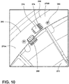
- the visual interface 26 includes four LPCB assemblies 270A-270D, collectively referred to as the LPCB assemblies 270.
- each of the LPCB assemblies 270 is shaped as a quarter-circle. Accordingly, the four LPCB assemblies 270 are coupled together to form a substantially circular or oblong light ring 30.
- the LPCB assemblies 270 are coupled together via male and female pin connections 274, 278.
- a first end 282 of each of the LPCB assemblies 270 includes the female pin connection 278 and a second opposing end 286 includes the male pin connection 274.
- At least one of the LPCB assemblies 270 is operably and/or electrically coupled to the microcontroller 42 via a connector 290. Accordingly, the LPCB assembly 270A coupled to the microcontroller 42 is activated and deactivated by the microcontroller 42, and the other LPCB assemblies 270B-270D are activated and deactivated, respectively, through the male and female pin connections 274, 278. In other words, the microcontroller 42 can selectively activate (e.g., illuminate) each of the LPCB assemblies 270.
- each of the LPCB assemblies 270 is mechanically fastened to the inner surface 272 of the door 18 surrounding the deflector 70. Accordingly, the LPCB assemblies 270 may be coupled to the inner surface 272 via fasteners 298, such as, for example, pins, screws, bolts, or other similar coupling members. As illustrated in FIG. 9 , each LPCB assembly 270 is coupled to the interior surface via three fasteners 298, however, more or fewer fasteners 298 may be used without departing from the teachings herein.
- the outer surface 94 of the door 18 is positioned over the LPCB assemblies 270 to provide for the visual interface 26.
- the outer surface 94 may be a transparent or translucent material such as, for example, acrylic, plastic, glass, tinted glass, and/or a combination thereof. It is contemplated that the outer surface 94 can include a tinted material with a non-tinted portion configured to align with the LPCB assemblies 270 to form the light ring 30. Such a configuration is advantageous to increase the brightness of the light ring 30.
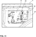
- the microcontroller 42 is coupled to the inner surface 272 of the door 18 within an enclosure 300. Accordingly, the microcontroller 42 is typically set back from the surrounding inner surface 272 of the door 18.
- the enclosure 300 is advantageous for reducing and/or limiting exposure of the microcontroller 42 to heat and moisture produced by the laundry appliance 10 and/or an external environment.
- the microcontroller 42 can be positioned proximate to the left side edge 86 and the top edge 54 of the door 18 but may be positioned elsewhere in the door 18.
- the microcontroller 42 may be configured as a "Raspberry Pi®" or other configurations of single-board computers.
- the microcontroller 42 is mechanically fastened to the inner surface 272 of the door 18 via the fasteners 298. As illustrated in FIG. 11 , the microcontroller 42 is coupled to the door 18 via four fasteners 298.
- the microcontroller 42 is operably coupled to the audio interface 34 and the visual interface 26. Accordingly, the microcontroller 42 is operably coupled to the speakers 102, the MPCB assembly 166, and the LPCB assemblies 270, such that the visual and audio interfaces 26, 34 can operate together and separately.
- the microcontroller 42 is configured to activate the microphone assembly 38 in response to sensed information received from the proximity sensor 210. The microcontroller 42 can then send a corresponding signal to the speakers 102 to provide an audio output and/or a corresponding signal to the visual interface 26 to provide a visual message to the user.
- the LPCB assemblies 270 can be selectively activated in response to the voice command.
- a door opening assembly 304 may be coupled to the door 18.
- the door opening assembly 304 includes a motor 308, which is illustrated adjacent to the right side edge 90 and the bottom edge 62 of the door 18.
- the motor 308 is illustrated as being mechanically fastened to the inner surface 272 of the door 18 via two fasteners 298.
- the door opening assembly 304 may be positioned elsewhere on the door 18.
- the door opening assembly 304 is operably coupled to the microcontroller 42.
- the MPCB assembly 166 sends a signal to the microcontroller 42, which then sends a corresponding signal to the door opening assembly 304. Accordingly, the door 18 of the laundry appliance 10 can be opened via voice commands.
- the door opening assembly 304 positioned on the door 18 is advantageous for separating the door opening assembly 304 from a higher-voltage door lock assembly coupled to the cabinet 14.
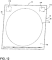
- the user-interface system 22 includes a tactile interface 312.
- the tactile interface 312 includes at least one touch printed circuit board (TPCB) assembly 316.
- TPCB touch printed circuit board
- the tactile interface 312 includes two TPCB assemblies 316 positioned adjacent to the left and right side edges 86, 90 and the top edge 54 of the door 18, respectively.
- the TPCB assemblies 316 are typically accessible via the outer surface 94 of the door 18.
- the TPCB assemblies 316 are coupled directly to the glass outer surface 94 of the door 18.
- the TPCB assemblies 316 can provide for a capacitive touch response.
- the TPCB assemblies 316 correspond with a power button 320 and a start button 324 on the outer surface 94 of the door 18.
- the microphone assembly 38 provides increased quality to the audio interface 34. Further, the microphone assembly 38, including the locating gasket 162 and the acoustic layer 170, isolate the PCB 202 and the microphones 206 from vibrations that can interfere with the audio interface 34. Additionally, the microphone assembly 38 can increase the reliability of voice command recognition due to the positioning of the components of the microphone assembly 38. Also, the microphone assembly 38 can recognize a voice command from a greater distance. Further, the geometries of the microphone port apertures 226 of the acoustic layer 170 typically reduce an echo produced by the voice command.
- the addition of the acoustic layer 170 allows the microphone assembly 38 to be compressed into the handle 82 of the door 18 with minimal interference in the microphone assembly 38 operation.
- the user-interface system 22 provides a combined system including the audio interface 34, the visual interface 26, and the tactile interface 312. Additionally, the user-interface system 22 is advantageously positioned within the door 18 of the laundry appliance 10. Additional benefits and advantages of using this device may also be realized and/or achieved.
- the device disclosed herein is further summarized in the following paragraphs and is further characterized by combinations of any and all of the various aspects described therein.
- a laundry appliance includes a cabinet.
- a door is coupled to the cabinet. The door is operable between a closed position and an opened position.
- a microphone assembly is coupled to the door. The microphone assembly is configured to receive a voice command.
- a microcontroller is coupled to the door. The microcontroller is operably coupled to the microphone assembly and the microcontroller.
- a proximity sensor is coupled to the microphone assembly. The proximity sensor defines a sensor field that extends outward from the door.
- a microphone assembly includes a printed circuit board assembly that has a plurality of microphones disposed thereon.
- a microphone assembly includes a locating gasket and an acoustic layer.
- a printed circuit board assembly is disposed between the locating gasket and the acoustic layer.
- a cover member is coupled to the door.
- the microphone assembly is compressed between a cover member and a back panel of a door.
- a cover member defines a microphone aperture that is configured to align with a microphone of a microphone assembly.
- a door defines an elongated channel proximate a handle.
- a microphone assembly is disposed in auditory communication with the handle.
- a proximity sensor is in communication with a microcontroller.
- the microcontroller is configured to activate a microphone assembly in response to sensed information received from the proximity sensor.
- a visual interface is coupled to the door and is configured to display a message.
- the message corresponds with a voice command received by a microphone assembly.
- an appliance door includes a door panel that has an outer surface and an inner surface.
- the door panel defines an elongated channel that is configured as a handle.
- An audio interface is disposed proximate the handle.
- the audio interface includes a speaker and a microphone printed circuit board assembly that has at least one microphone.
- a visual interface is coupled to the inner surface of the door. The visual interface is configured to display messages on the outer surface of the door.
- an acoustic layer includes a gasket disposed around a microphone and an acoustic mesh layer that extends over the gasket.
- a microphone printed circuit board assembly is configured to receive a voice command.
- a visual interface includes a plurality of light printed circuit board assemblies configured to selectively illuminate in response to the voice command.
- a door panel defines a pocket within an elongated channel.
- the pocket is surrounded by a raised border.
- a cover member is coupled to the door panel.
- the cover member defines a cutout.
- a raised border is disposed within the cutout to provide an interlocking connection.
- an acoustic layer is coupled to a microphone printed circuit board assembly.
- the acoustic layer defines at least one microphone port aperture configured to align with the at least one microphone.
- At least one microphone port aperture is a same size and dimension for an entire depth of an acoustic layer.
- a door assembly includes a door panel that forms a handle.
- a printed circuit board is coupled to the door panel proximate the handle.
- a plurality of microphones is coupled to a printed circuit board.
- An acoustic layer is coupled to the printed circuit board. Each microphone aligns with a microphone port aperture that is defined by the acoustic layer.
- a cover member is disposed at least partially within the handle. The cover member is disposed adjacent to the acoustic layer.
- a padded layer is disposed between a locating gasket and a door panel.
- a proximity sensor is coupled to a printed circuit board.
- the proximity sensor defines a sensor field that extends outwardly from a door panel.
- each microphone port aperture is a same size and dimension for an entire depth of an acoustic layer.
- a tactile interface is coupled to an outer surface of a door panel.
- the tactile interface is configured to provide for a capacitive touch response.
Landscapes
- Engineering & Computer Science (AREA)
- Textile Engineering (AREA)
- Physics & Mathematics (AREA)
- Acoustics & Sound (AREA)
- Multimedia (AREA)
- Human Computer Interaction (AREA)
- Audiology, Speech & Language Pathology (AREA)
- Health & Medical Sciences (AREA)
- Theoretical Computer Science (AREA)
- Signal Processing (AREA)
- Computational Linguistics (AREA)
- General Health & Medical Sciences (AREA)
- General Engineering & Computer Science (AREA)
- General Physics & Mathematics (AREA)
- Main Body Construction Of Washing Machines And Laundry Dryers (AREA)
- Control Of Washing Machine And Dryer (AREA)
Abstract
Description
- The present disclosure generally relates to a user-interface system, and more specifically, to a user-interface system for a laundry appliance.
- Laundry appliances typically include a user-interface for a user to enter commands to control the laundry appliance. The user-interface may include a microphone, which allows the user to control the laundry appliance via voice commands. Additionally, user-interfaces may include a visual indicator, such as a display screen.
- According to one aspect of the present disclosure, a laundry appliance includes a cabinet. A door is coupled to the cabinet. The door is operable between a closed position and an opened position. A microphone assembly is coupled to the door. The microphone assembly is configured to receive a voice command. A microcontroller is coupled to the door. The microcontroller is operably coupled to the microphone assembly. A proximity sensor is coupled to the microphone assembly and the microcontroller. The proximity sensor defines a sensor field that extends outward from the door.
- According to another aspect of the present disclosure, an appliance door includes a door panel that has an outer surface and an inner surface. The door panel defines an elongated channel that is configured as a handle. An audio interface is disposed proximate the handle. The audio interface includes a speaker and a microphone printed circuit board assembly that has at least one microphone. A visual interface is coupled to the inner surface of the door. The visual interface is configured to display messages on the outer surface of the door.
- According to another aspect of the present disclosure, a door assembly includes a door panel that forms a handle. A printed circuit board is coupled to the door panel proximate the handle. A plurality of microphones is coupled to a printed circuit board. An acoustic layer is coupled to the printed circuit board. Each microphone aligns with a microphone port aperture that is defined by the acoustic layer. A cover member is disposed at least partially within the handle. The cover member is disposed adjacent to the acoustic layer.
- These and other features, advantages, and objects of the present disclosure will be further understood and appreciated by those skilled in the art by reference to the following specification, claims, and appended drawings.
- In the drawings:
-
FIG. 1 is a front perspective view of a laundry appliance with a door in a closed position, according to at least one example; -
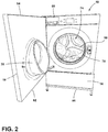
FIG. 2 is a front perspective view of the laundry appliance with the door in an opened position, according to at least one example; -
FIG. 3 is a front perspective view of an outer surface of the door in the opened position, according to at least one example; -
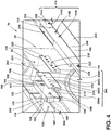
FIG. 4 is an exploded perspective view of a microphone assembly, according to at least one example; -
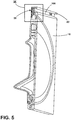
FIG. 5 is a cross-sectional view of the door ofFIG. 3 taken along line VII-VII, according to at least one example; -
FIG. 6 is an enlarged cross-sectional view ofFIG. 7 , taken at area VIII; -
FIG. 7 is a partial interior bottom view of a microphone assembly of the door, according to at least one example; -
FIG. 8 is an enlarged partial perspective view of a cover member defining microphone apertures, according to at least one example; -
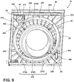
FIG. 9 is a perspective view of a rear surface of the door ofFIG. 3 , with the inner panel removed, according to at least one example; -
FIG. 10 is an enlarged partial interior perspective view of a visual interface coupled to the door, according to at least one example; -
FIG. 11 is an enlarged partial perspective view of the microcontroller for the door, according to at least one example; and -
FIG. 12 is a front perspective view of the door including a tactile interface, according to at least one example. - The components in the figures are not necessarily to scale, emphasis instead being placed upon illustrating the principles described herein.
- The present illustrated embodiments reside primarily in combinations of method steps and apparatus components related to a microphone assembly for a laundry appliance. Accordingly, the apparatus components and method steps have been represented, where appropriate, by conventional symbols in the drawings, showing only those specific details that are pertinent to understanding the embodiments of the present disclosure so as not to obscure the disclosure with details that will be readily apparent to those of ordinary skill in the art having the benefit of the description herein. Further, like numerals in the description and drawings represent like elements.
- For purposes of description herein, the terms "upper," "lower," "right," "left," "rear," "front," "vertical," "horizontal," and derivatives thereof shall relate to the disclosure as oriented in
FIG. 1 . Unless stated otherwise, the term "front" shall refer to the surface of the element closer to an intended viewer, and the term "rear" shall refer to the surface of the element further from the intended viewer. However, it is to be understood that the disclosure may assume various alternative orientations, except where expressly specified to the contrary. It is also to be understood that the specific devices and processes illustrated in the attached drawings, and described in the following specification are simply exemplary embodiments of the inventive concepts defined in the appended claims. Hence, specific dimensions and other physical characteristics relating to the embodiments disclosed herein are not to be considered as limiting, unless the claims expressly state otherwise. - The terms "including," "comprises," "comprising," or any other variation thereof, are intended to cover a non-exclusive inclusion, such that a process, method, article, or apparatus that comprises a list of elements does not include only those elements but may include other elements not expressly listed or inherent to such process, method, article, or apparatus. An element proceeded by "comprises a ... " does not, without more constraints, preclude the existence of additional identical elements in the process, method, article, or apparatus that comprises the element.
- Referring to
FIGS. 1-12 ,reference numeral 10 generally designates a laundry appliance including acabinet 14 and adoor 18 rotatably coupled to thecabinet 14. A user-interface system 22 is coupled to thedoor 18 and includes avisual interface 26 defining alight ring 30 and anaudio interface 34. Theaudio interface 34 includes amicrophone assembly 38. The user-interface system 22 includes amicrocontroller 42 operably coupled to the visual andaudio interfaces - Referring to
FIGS. 1 and2 , thelaundry appliance 10 includes thecabinet 14 having afront surface 46 and adoor 18 rotatably coupled to thecabinet 14. Thedoor 18 may be a flat panel door, a fishbowl-style door, and/or a combination thereof. As illustrated in the exemplary embodiment inFIG. 1 , thelaundry appliance 10 is a front-load, horizontalaxis laundry appliance 10. However, thelaundry appliance 10 may be a washer, dryer, and/or a combination thereof. For example, thelaundry appliance 10 can be a top-load laundry appliance 10 or another configuration of a front-load laundry appliance 10. Thedoor 18 is operable between opened and closed positions. Thedoor 18, in the exemplary embodiment ofFIG. 1 , opens in a side-to-side manner, however, it is contemplated that thedoor 18 can open in an up-and-down manner. Thedoor 18 is configured to allow access to adrum 50 positioned within thecabinet 14 when in an opened position, and encloses thedrum 50 when in the closed position. - In various examples, a
top edge 54 of thedoor 18 is substantially coplanar with atop surface 58 of thecabinet 14. A decorative panel may also be placed over thetop surface 58 of thecabinet 14 and thetop edge 54 of the door 187. Additionally or alternatively, abottom edge 62 of thedoor 18 is spaced-apart from abottom surface 66 of thecabinet 14. However, it is contemplated that thebottom edge 62 of thedoor 18 can be coplanar with thebottom surface 66 of thecabinet 14. - As illustrated in
FIGS. 1 and2 , the door 18 (e.g., a door panel) has a substantially rectangular shape. The shape of thedoor 18 substantially aligns with the shape of thecabinet 14. In other words, thedoor 18 and thefront surface 46 of thecabinet 14 have substantially similar shapes. Alternatively, thedoor 18 and thefront surface 46 of thecabinet 14 may have different shapes. In such examples, thedoor 18 can have a substantially circular or oblong shape. - In certain aspects, a rear surface of the
door 18 defines and/or includes adeflector 70. In particular, where the appliance has a washing function, thedoor 18 typically includes thedeflector 70. When thedoor 18 is in the closed position, thedeflector 70 extends into thedrum 50 via anopening 74 in thefront surface 46 of thecabinet 14. Thedeflector 70 is advantageous for deflecting laundry away from thedoor 18 or abellows assembly 78, which is positioned about the perimeter of theopening 74 of thecabinet 14. - While illustrated as the
door 18 for thelaundry appliance 10, it is also contemplated that thedoor 18 may be included on other appliances, such as, for example, a dishwasher, an oven, a refrigerating appliance, a countertop appliance, etc. - Referring to
FIG. 3 , thedoor 18 includes ahandle 82 adjacent to thetop edge 54 of thedoor 18. It is contemplated that thehandle 82 may be located in other locations on thedoor 18, such as, for example, proximate to a left or aright side edge door 18. Anouter surface 94 of a rear panel of thedoor 18 partially defines an elongated cavity orchannel 98 proximate thehandle 82, which is typically positioned adjacent to thetop edge 54 of thedoor 18. Thedoor 18 can provide for a variety of configurations of theelongated channel 98. For example, theelongated channel 98 often extends between theleft side edge 86 to theright side edge 90 of thedoor 18. Typically, theelongated channel 98 extends the entire distance between the left and right side edges 86, 90. It is further contemplated that theelongated channel 98 may extend in a different direction along thedoor 18, such as, for example, between thetop edge 54 and thebottom edge 62 of thedoor 18. - Referring to
FIGS. 3 and4 , themicrophone assembly 38 and at least onespeaker 102 are coupled to thedoor 18 proximate thehandle 82 and are in auditory communication with thehandle 82. As illustrated inFIG. 3 , thelaundry appliance 10 includes twospeakers 102. Onespeaker 102 is positioned adjacent to theleft side edge 86 and theother speaker 102 is positioned adjacent to theright side edge 90 of thedoor 18 within theelongated channel 98. The configuration of themicrophone assembly 38 and thespeakers 102 can depend on a variety of factors. Moreorfewer speakers 102 may be included without departing from the teachings herein. Themicrophone assembly 38 is disposed proximate thehandle 82 and is disposed betweenspeakers 102. - A
cover member 106 at least partially defines theelongated channel 98. Theelongated channel 98 is defined between thecover member 106 and thedoor 18. Thecover member 106 definesspeaker apertures 110 for an audio output to be communicated to a user. Thecover member 106 additionally definesmicrophone apertures 114 for an input (e.g., a voice command) to be communicated from a user to themicrophone assembly 38. - The
cover member 106 can have a variety of configurations based on a number of factors, including, for example, the configuration of themicrophone assembly 38 and thespeakers 102. For example, as illustrated inFIGS. 3 and4 , thecover member 106 defines fourmicrophone apertures 114A-114D, collectively referred to as themicrophone apertures 114. However, the number ofmicrophone apertures 114 may be greater or fewer based on the configuration of themicrophone assembly 38. Additionally, thecover member 106 defines asensor aperture 118 disposed among themicrophone apertures 114 and typically between themicrophone apertures sensor aperture 118 may be the same size or a different size than themicrophone apertures 114. Each of thespeaker apertures 110, themicrophone apertures 114, and thesensor aperture 118 may be a single aperture or a plurality of apertures without departing from the teachings herein. - Referring to
FIGS. 1 and4-6 , thedoor 18 includes a channelinterior surface 122 defining apocket 126. Thepocket 126 is typically molded into thedoor 18, such that thepocket 126 is integrally formed with thedoor 18. Other configurations are also contemplated based on the configuration of themicrophone assembly 38. Thepocket 126 can be offset from the channelinterior surface 122 by a raisedborder 130 or can extend into the channelinterior surface 122 forming a recessed portion. The raisedborder 130 extends outward (e.g., forward) from the channelinterior surface 122 and typically surrounds thepocket 126. Accordingly, arear pocket surface 134 may be substantially coplanar with the channelinterior surface 122. Alternatively, therear pocket surface 134 may be setback from the channelinterior surface 122. Typically, thepocket 126 has a substantially rectangular shape, however, it is contemplated that thepocket 126 may be any shape based on the configuration of themicrophone assembly 38. - The
rear pocket surface 134 defines locatingprotrusions 138 extending outward towards afront 142 of thelaundry appliance 10. The specific configuration may vary based on the configuration of themicrophone assembly 38 and/or thelaundry appliance 10. For example, in the illustrated example ofFIG. 4 , thepocket 126 includes two locatingprotrusions 138. However, more or fewer locatingprotrusions 138 may be included without departing from the teachings herein. The number of locatingprotrusions 138 is often based on the size and/or shape of themicrophone assembly 38 and/or thedoor 18. The locatingprotrusions 138 may be substantially cylindrical or frusto-conical or any other practicable shape. The locatingprotrusions 138 are illustrated inFIG. 4 as extending a substantially same distance from therear pocket surface 134. Alternatively, the locatingprotrusions 138 may extend different distances from therear pocket surface 134. - Further, the configuration may depend on the configuration of the mating components. In a specific configuration, the locating
protrusions 138, as illustrated, are positioned substantially the same distance from opposing lateral sides of thepocket 126, respectively. Additionally, the locatingprotrusions 138 are positioned along a horizontal midpoint of thepocket 126. In other words, the locatingprotrusions 138 are positioned substantially equidistant from upper and lower sides of thepocket 126. These configurations and locations of theprotrusions 138 are contemplated. Accordingly, the positioning of the locatingprotrusion 138 is generally dependent on the location of corresponding locatingchannels 160 defined in a locatinggasket 162 of themicrophone assembly 38 that are configured to receive the locatingprotrusions 138. The locations of the locatingprotrusion 138 and the locatingchannels 160 can vary depending on the design of the device and locations of various components. - Referring still to
FIGS. 4-6 , theaudio interface 34 of thelaundry appliance 10 includes themicrophone assembly 38 for receiving a user input via voice commands and the speaker 102 (FIG. 1 ) for projecting an audio output to the user. Themicrophone assembly 38 includes the locatinggasket 162 and a microphone printed circuit board (MPCB)assembly 166 including at least onemicrophone 206. TheMPCB assembly 166 is coupled to the locatinggasket 162. Additionally, themicrophone assembly 38 includes anacoustic layer 170 coupled to theMPCB assembly 166 on an opposing side relative to the locatinggasket 162. - Referring again to
FIGS. 1 and4-6 , the locatinggasket 162 is configured to be positioned within thepocket 126 of thehandle 82 defined by the channelinterior surface 122 when thehandle 82 is assembled. The locatinggasket 162 can have a variety of configurations. The locatinggasket 162, as illustrated inFIG. 4 , has a substantially rectangular shape. However, the locatinggasket 162 may have any shape that substantially corresponds with the shape of thepocket 126 to produce a form-fitting connection. The configuration of the locatinggasket 162 can vary based on the configuration of the device. For example,outer surfaces 174 of the locatinggasket 162 abut the raisedborder 130 that defines thepocket 126. The border can be continuous or can include interruptions and gaps in the structure that surrounds and defines thepocket 126. Theouter surfaces 174 of the locatinggasket 162 can directly abut the channelinterior surface 122 that defines thepocket 126. The locatinggasket 162 is configured to substantially fill thepocket 126. In such examples, there is typically not a gap between the locatinggasket 162 and therear pocket surface 134. Accordingly, thepocket 126 and the locatinggasket 162 may have substantially similar depths. However, it is contemplated that the locatinggasket 162 may have a greater depth compared to thepocket 126 to engage thecover member 106 without departing from the teachings herein. - The locating
gasket 162 defines the locatingchannels 160 configured to align with and receive the locatingprotrusions 138. When assembled, the locatingprotrusions 138 extend into and/or through the locatingchannels 160. The engagement between the locatingprotrusions 138 and the locatingchannels 160 is advantageous for providing proper alignment between thepocket 126 and the locatinggasket 162. Accordingly, the number of locatingchannels 160 typically corresponds with the number of locatingprotrusions 138. - In a non-limiting example, the locating
channels 160 extend through the entire depth of the locatinggasket 162. In other words, the locatingchannels 160 extend from aninward surface 182 of the locatinggasket 162 to anoutward surface 186 of the locatinggasket 162. In such examples, the locatingprotrusions 138 can extend all or part of a length of the locatingchannels 160, respectively. In another non-limiting example, the locatingchannels 160 extend a portion of the depth of the locatinggasket 162. In such examples, the length of the locatingchannels 160 can align with the length of the locatingprotrusions 138, respectively. The size and/or shape of the locatingchannels 160 is typically determined by the size and/or shape of the locatingprotrusions 138 to produce a form-fitting connection that minimizes unwanted noise and vibration. - The locating
gasket 162 includes locatingprojections 180 extending from theoutward surface 186 of the locatinggasket 162. The locatingprojections 180 may each define anend opening 188 of the locatingchannels 160, respectively, in exemplary embodiments where the locatingchannels 160 extend between the inward andoutward surfaces gasket 162. It is contemplated that the locatingprojections 180 may define a solid surface and may not define the openings to the locatingchannels 160, respectively. In such an embodiment, the locatingprojections 180 may act as a stop for positioning the alignment protrusions within the locatinggasket 162. The locatingprojections 180 are advantageous for providing proper alignment between theMPCB assembly 166 and the locatinggasket 162. - Referring still to
FIGS. 1 and4-6 , the locatinggasket 162 includes arim 190 extending along a perimeter thereof to position various components of themicrophone assembly 38. Therim 190 may extend around the entire perimeter, or alternatively, therim 190 may extend around a portion of the perimeter. For example, therim 190 may be configured as segments that extend aroundcorners 194 of the locatinggasket 162. Therim 190 and the locatingprojections 180 can have varying configurations based on the configuration of the device and arrangement of various components. For example, therim 190 and the locatingprojections 180 typically extend a substantially similar distance from theouter surface 94 of the locatinggasket 162. Alternatively, either the locatingprojections 180 or therim 190 may extend a greater distance. The configuration of therim 190 and the locatingprojections 180 vary based on the configuration of thepocket 126 and thedoor 18 of thelaundry appliance 10. Anupper surface 192 of therim 190 may extend past the raisedborder 130 defining thepocket 126. - The locating
gasket 162 typically is vibration resistant, absorbs vibrations, and/or reduces vibrations. The locatinggasket 162 includes elastomeric materials, such as, for example, silicone or rubber. The locatinggasket 162 reduces vibrations within themicrophone assembly 38. Additionally or alternatively, the locatinggasket 162 is advantageous for isolating noise and/or vibrations of the laundry appliance 10 (e.g., caused by operation of the laundry appliance 10) from themicrophone assembly 38. Isolating themicrophone assembly 38 via the locatinggasket 162 is advantageous for increasing the quality of theaudio interface 34. Further, the locatinggasket 162 is advantageous for increasing the reliability of the voice and/or input recognition given through voice commands through the isolation of themicrophone assembly 38. - Referring still to
FIGS. 4 and6 , in various examples, theMPCB assembly 166 is coupled to the locatinggasket 162. Therim 190 of the locatinggasket 162 defines aspace 198 that substantially corresponds with the size and shape of theMPCB assembly 166. Theupper surface 192 of therim 190 is often coplanar with theMPCB assembly 166 when theMPCB assembly 166 is coupled to the locatinggasket 162. TheMPCB assembly 166 includes a printed circuit board (PCB) 202 and at least onemicrophone 206 disposed thereon. ThePCB 202 includes a control having control circuitry with microphone drive circuitry for controlling activation and deactivation of themicrophone 206. Additionally or alternatively, thePCB 202 includes sensor drive circuitry for controlling activation and deactivation of aproximity sensor 210 positioned on or coupled with thePCB 202. ThePCB 202 may be any type of circuit board including, but not limited to, any flexible PCB and/or rigid PCB. - The
MPCB assembly 166 definesholes 214 configured to align with the locatingprojections 180 of the locatinggasket 162. At least one of therim 190 and the locatingprojections 180 operate to align with theMPCB assembly 166 within the locatinggasket 162. Proper alignment of theMPCB assembly 166 is advantageous for maximizing the reliability of theaudio interface 34. In other words, proper alignment is advantageous for reducing interference between themicrophone 206 and the voice command given by the user. The locatingprojections 180 extend into and/or through theholes 214 of theMPCB assembly 166. - The
MPCB assembly 166 can have a variety of configurations based on the configuration of thelaundry appliance 10. As illustrated inFIG. 4 , theMPCB assembly 166 typically includes fourmicrophones 206A-206D, collectively referred to asmicrophones 206. Themicrophones 206 are configured to receive a voice command from a user. More orfewer microphones 206 may be included without departing from the teachings herein. In a specific example, one of themicrophones 206 is positioned on each opposing side of one of theholes 214 defined by the MPCB assembly 166 (e.g., themicrophones microphones 206 on theMPCB assembly 166 are contemplated and may be advantageous based on the configuration of themicrophone assembly 38 and thedoor 18. - Referring again to
FIGS. 1 ,4 , and6 , theproximity sensor 210 is coupled to theMPCB assembly 166. Theproximity sensor 210 is disposed among themicrophones 206, and typically disposed in acenter portion 216 of theMPCB assembly 166 with themicrophones proximity sensor 210. Theproximity sensor 210 defines asensor field 218 extending outwardly (e.g., generally forward) from thefront 142 of thelaundry appliance 10. Accordingly, theproximity sensor 210 is configured to sense when a user is approaching thefront 142 of thelaundry appliance 10. Theproximity sensor 210 and/or an associated controller may include a temporal component, which is advantageous for differentiating between a user approaching thefront 142 of thelaundry appliance 10 to give a voice command and a person walking past thefront 142 of thelaundry appliance 10. Proper alignment of theMPCB assembly 166 within the locatinggasket 162 and the locatinggasket 162 within thepocket 126 is also advantageous for preventing interference with thesensor field 218 due to misalignment. - Referring still to
FIG. 4 and6 , themicrophone assembly 38 includes theacoustic layer 170 coupled to theMPCB assembly 166. Theacoustic layer 170 typically includes foam materials or other vibration resistant and/or absorbent materials that minimize unwanted noise and vibration. Additionally, theacoustic layer 170 often includes materials that are resiliently and elastically compressible. Theacoustic layer 170 is advantageous for isolating theMPCB assembly 166 from vibrations that may affect the reliability of theaudio interface 34. The configuration of theacoustic layer 170 can vary based on the configuration of the device. For example, theacoustic layer 170, has a height that is less than a height of theMPCB assembly 166. However, it is contemplated that theacoustic layer 170 can have a substantially similar height or a greater height based on the configuration of themicrophone assembly 38 and thedoor 18. Theacoustic layer 170 can be offset and spaced-apart from theupper surface 192 of therim 190 of the locatinggasket 162, or alternatively, positioned and/or retained by therim 190 of the locatinggasket 162. Accordingly, theacoustic layer 170 may be coplanar with theupper surface 192 of therim 190. - The
acoustic layer 170 defines locatingport apertures 222,microphone port apertures 226, and asensor port aperture 230. The locatingport apertures 222 are configured to align with the locatingprojections 180 of the locatinggasket 162. In such examples, the locatingprojections 180 extend through theMPCB assembly 166 and into and/or through the locatingport apertures 222 of theacoustic layer 170. Further, the number, size, and/or shape of the locatingport apertures 222 depend on the number, size, and shape of the locatingprojections 180. The shape and/or size of the locatingport apertures 222 can be substantially the same as the shape and/or size of themicrophone port apertures 226. - The
microphone port apertures 226 are illustrated as having a substantially circular or oblong shape; however, themicrophone port apertures 226 may also have a substantially square, rectangular, or another polygonal shape. Themicrophone port apertures 226 can vary the reliability and accuracy of themicrophones 206. Typically, themicrophone port apertures 226 have the same shape through the entire assembly. Specifically, themicrophone port apertures 226 extend through theacoustic layer 170 and have the same shape, diameter, and/or width through the length of themicrophone port apertures 226, respectively. In other words, the shape, diameter, and/or width of eachmicrophone port aperture 226 is the same at afirst surface 234 of theacoustic layer 170, at asecond surface 236 of theacoustic layer 170, and at each point therebetween (e.g., through the entire depth of the acoustic layer 170). The consistent diameter and/or width is advantageous for reducing an echo that can be produced by sound waves from a voice command traveling through themicrophone port aperture 226. A change in the shape, diameter, and/or width of themicrophone port apertures 226 typically alters a direction of the sound waves of the voice command and produces an echo or other undesirable sound interference, which reduces the reliability of theaudio interface 34. As such, each of themicrophone port apertures 226 is substantially the same to increase the reliability of each of themicrophones 206, respectively. - Referring still to
FIGS. 1 ,4 , and6 , theacoustic layer 170 defines thesensor port aperture 230. Theproximity sensor 210 positioned on theMPCB assembly 166 aligns with and extends into and/or through thesensor port aperture 230. As illustrated inFIG. 4 , thesensor port aperture 230 has a substantially square and/or rectangular shape. The shape and size of thesensor port aperture 230 is defined by the shape and/or size of theproximity sensor 210. Theacoustic layer 170 is advantageous for properly positioning theproximity sensor 210. Additionally or alternatively, theacoustic layer 170 is advantageous for maximizing thesensor field 218 of theproximity sensor 210. - The
microphone assembly 38 is enclosed and compressed within theelongated channel 98 between thecover member 106 and thedoor 18. Thecover member 106 often abuts theacoustic layer 170. Thecover member 106 typically includes a plastic material and may include the same material as thedoor 18 of thelaundry appliance 10. In various examples, thecover member 106 is an injection molded component. Thecover member 106 extends from theleft side edge 86 to theright side edge 90 of thedoor 18. Thecover member 106 includes aflange 238 that extends over anupper pocket surface 242. Theflange 238 defines acutout 246 configured to align with thepocket 126 defined by therear pocket surface 134. Theupper pocket surface 242 and/or the raisedborder 130 is typically offset from a surrounding upper surface and is configured to form an interlocking connection with theflange 238 when positioned within thecutout 246. - The
cover member 106 includes afirst wall 250 and asecond wall 254. Thefirst wall 250 may be substantially vertical and configured to be positioned adjacent to theacoustic layer 170 when thedoor 18 is assembled. Thesecond wall 254 typically extends forward from thefirst wall 250. As exemplified inFIG. 6 , thesecond wall 254 extends at an angle in a range of from about 30° to about 60° from abottom 258 of thefirst wall 250. Thesecond wall 254 extends towards thefront 142 of thelaundry appliance 10 and away from themicrophone assembly 38 and is configured to couple to theouter surface 94 of thedoor 18. The first andsecond walls handle 82 available for grasping. - It is contemplated that the
audio interface 34 may have different configurations, as illustrated inFIG. 7 . Referring toFIGS. 1 ,4 , and7 , theMPCB assembly 166 can contact thecover member 106 and the channelinterior surface 122 directly. Aback surface 328 of thecover member 106 defines mountingbosses 332 extending outward towards therear pocket surface 134 when thedoor 18 is assembled. Theholes 214 defined by theMPCB assembly 166 correspond with and align with the mountingbosses 332 of thecover member 106. Accordingly, theMPCB assembly 166 defines at least a sufficient number ofholes 214 to accommodate the mountingbosses 332. The mountingbosses 332 are advantageous for positioning theMPCB assembly 166 to maximize soundwaves reaching themicrophones 206. - The
back surface 328 of thecover member 106 may define raised ribs or supports 336. The raised supports 336 may define patterns on theback surface 328 of thecover member 106 that corresponds to the configuration of themicrophone assembly 38. As illustrated inFIG. 7 , the raisedsupports 336 can define four circles spaced-apart within an oblong raisedsupport 338. The four circular raisedsupports 336 correspond with themicrophone apertures 114 defined by thecover member 106. Further, each of the circular raisedsupports 336 may be configured to correspond with onemicrophone 206 of theMPCB assembly 166. Further, the oblong raisedsupport 338 may correspond with a length of theMPCB assembly 166. In various examples, theacoustic layer 170 may includegaskets 340 each configured to align with onemicrophone 206 and thecorresponding microphone aperture 114, respectively. Accordingly, each of thegaskets 340 may be positioned within or otherwise coupled with the circular raised supports 336. Thegaskets 340 may be advantageous for providing a seal around themicrophones 206 to focus the sound waves into the microphones. Anadditional gasket 340 can be included around theproximity sensor 210 and the correspondingsensor port aperture 118. - In various examples, an
acoustic mesh layer 344 may be disposed on or otherwise coupled with each of thegaskets 340, respectively. Theacoustic mesh layer 344 partially or entirely extends across thegaskets 340. Theacoustic mesh layer 344 is advantageous for providing ingress protection between themicrophone apertures 114 and themicrophones 206. Additionally, theacoustic mesh layer 344 can minimally and/or not interfere with soundwaves traveling to themicrophones 206. TheMPCB assembly 166 typically abuts thegaskets 340 when assembled with the mountingbosses 332 of thecover member 106. - Referring to
FIGS. 4 and7 , when assembled, the device can have a variety of configurations. As illustrated inFIG. 4 , the locatinggasket 162 can be disposed in thepocket 126. In another example, as illustrated inFIG. 5 , an opposing side of theMPCB assembly 166 abuts therear pocket surface 134 of thepocket 126. Alternatively, in examples without thepocket 126, theMPCB assembly 166 abuts the channelinterior surface 122 of theelongated channel 98. In other words, themicrophone assembly 38 may not include the locatinggasket 162 but can include another elastomeric member. Thegaskets 340 take the place of the locatinggasket 162. It is contemplated that the channelinterior surface 122 can be substantially flat or include ribs or other surface features. The ribs or other surface features assist in retaining theMPCB assembly 166 in proper alignment. TheMPCB assembly 166 is compressed between thegaskets 340 and the channelinterior surface 122. When compressed therebetween, theMPCB assembly 166 compresses thegaskets 340 to abut the raisedsupports 336 defined by theback surface 328 of thecover member 106. The exemplary embodiments of theaudio interface 34, illustrated inFIGS. 4 and7 , are both configured to reduce interference with the microphone assembly 38 (e.g., from vibrations from the laundry appliance 10) and increasing reliability of theaudio interface 34 by reducing interference with sound waves traveling to themicrophones 206. - Referring to
FIGS. 4 and8 , themicrophone apertures 114 defined by thecover member 106 may be configured in a variety of ways. As illustrated, themicrophone apertures 114 are arranged in groupings ofmicrophone apertures 114. The groupings ofmicrophone apertures 114 are advantageous to direct the sound waves of the voice command to themicrophone port apertures 226, respectively. Each of the groupings ofmicrophone apertures 114 aligns with a singlemicrophone port aperture 226 of theacoustic layer 170 to direct the voice command to thecorresponding microphone 206. The alignment of therespective microphone apertures 114 and themicrophone port aperture 226 increases the reliability and accuracy of themicrophones 206. As illustrated, the groupings ofmicrophone apertures 114 are arranged in vertically stacked configurations. The illustrated configuration may provide for proper spacing of themicrophones 206. Specific spacing of themicrophones 206 in the illustrated array may be advantageous for more clearly receiving voice commands and more effectively filtering directional sound and noise. - In certain aspects, the
microphones 206 may be arranged at predefined distances relative to one another in the array. Software (e.g., algorithms) within themicrocontroller 42 or another associated controller can use the position and spacing of themicrophones 206, as well as a time difference for the arrival of sound to eachmicrophone 206 to calculate a location of the source of the sound. This pairing between the positioning of themicrophones 206 and the software allows the software to identify the speaker of a voice command and distinguish the sound from the speaker from other sounds from a different calculated position. The relative location of themicrophones 206 affects when eachmicrophone 206 receives sound waves, and therefore effects the calculation for determining the location of the source of the sound. - The illustrated configuration of the
microphone apertures 114 in the vertically stacked configuration is merely exemplary. The vertically stacked configuration provided for a chamber to reduce microphone position tolerance in the illustrated example. However, the configuration can be changed to any practicable positioning of themicrophones 206 and arrangement of themicrophone apertures 114 based on the pairing with different software. - Referring to
FIGS. 4-6 , themicrophone assembly 38 is compressed between thedoor 18 and thecover member 106. Theacoustic layer 170 allows themicrophone assembly 38 to be compressed between thedoor 18 and thecover member 106 with minimal interference in the operation of themicrophone assembly 38. The positioning of themicrophone assembly 38 increases the reliability of theaudio interface 34. In such examples, the positioning can increase the reliability of themicrophone 206 detecting specified commands from various distances. - The
microphone assembly 38 is positioned proximate thehandle 82 behind thecover member 106. Thecover member 106 includesribs 262 extending from thesecond wall 254 for increased structural strength of thecover member 106. The increased strength is advantageous as thecover member 106 defines thehandle 82 of thedoor 18, which is grabbed and pulled by the user to move thedoor 18 to the opened position. The locatinggasket 162 can define upper andlower notches gasket 162 within thepocket 126. Additionally or alternatively, themicrophone assembly 38 may include apadded layer 266. The paddedlayer 266 typically includes similar materials to the locatinggasket 162 and/or theacoustic layer 170. The paddedlayer 266 is positioned between the locatinggasket 162 and therear pocket surface 134. The paddedlayer 266 provides additional vibration absorption and/or vibration resistance for isolating themicrophone assembly 38 from vibrations. - Referring to
FIGS. 1-8 , each of the components of themicrophone assembly 38 may be adhered together. For example, theMPCB assembly 166 is adhered to the locatinggasket 162, theacoustic layer 170 is adhered to theMPCB assembly 166, and the locatinggasket 162 is adhered within thepocket 126. Thecover member 106 may then be adhered over themicrophone assembly 38. Other methods of coupling and/or attaching themicrophone assembly 38 and thecover member 106 are also contemplated without departing from the teachings herein. - Referring to
FIGS. 1 ,9 , and10 , thelaundry appliance 10 includes thevisual interface 26 for conveying messages to the user. Thevisual interface 26 defines thelight ring 30 on theouter surface 94 of thedoor 18. While illustrated as alight ring 30, thevisual interface 26 may define any shape, plurality of shapes, or other animation without departing from the teachings herein. Typically, thevisual interface 26 is coupled to aninner surface 272 of thedoor 18 and configured to display messages on theouter surface 94 of thedoor 18. Thevisual interface 26 includes at least one light printed circuit board (LPCB)assembly 270. TheLPCB assembly 270 includes light drive circuitry for controlling activation and deactivation of thelight ring 30. Thevisual interface 26 can have a variety of configurations for displaying messages. As illustrated inFIG. 9 , thevisual interface 26 includes fourLPCB assemblies 270A-270D, collectively referred to as theLPCB assemblies 270. In certain aspects of the device, each of theLPCB assemblies 270 is shaped as a quarter-circle. Accordingly, the fourLPCB assemblies 270 are coupled together to form a substantially circular or oblonglight ring 30. - The
LPCB assemblies 270 are coupled together via male andfemale pin connections first end 282 of each of theLPCB assemblies 270 includes thefemale pin connection 278 and a secondopposing end 286 includes themale pin connection 274. At least one of theLPCB assemblies 270 is operably and/or electrically coupled to themicrocontroller 42 via aconnector 290. Accordingly, theLPCB assembly 270A coupled to themicrocontroller 42 is activated and deactivated by themicrocontroller 42, and theother LPCB assemblies 270B-270D are activated and deactivated, respectively, through the male andfemale pin connections microcontroller 42 can selectively activate (e.g., illuminate) each of theLPCB assemblies 270. - In various examples, each of the
LPCB assemblies 270 is mechanically fastened to theinner surface 272 of thedoor 18 surrounding thedeflector 70. Accordingly, theLPCB assemblies 270 may be coupled to theinner surface 272 viafasteners 298, such as, for example, pins, screws, bolts, or other similar coupling members. As illustrated inFIG. 9 , eachLPCB assembly 270 is coupled to the interior surface via threefasteners 298, however, more orfewer fasteners 298 may be used without departing from the teachings herein. - Referring to
FIGS. 1 and9 , theouter surface 94 of thedoor 18 is positioned over theLPCB assemblies 270 to provide for thevisual interface 26. In various examples, theouter surface 94 may be a transparent or translucent material such as, for example, acrylic, plastic, glass, tinted glass, and/or a combination thereof. It is contemplated that theouter surface 94 can include a tinted material with a non-tinted portion configured to align with theLPCB assemblies 270 to form thelight ring 30. Such a configuration is advantageous to increase the brightness of thelight ring 30. - Referring to
FIGS. 1 ,9 , and11 , themicrocontroller 42 is coupled to theinner surface 272 of thedoor 18 within anenclosure 300. Accordingly, themicrocontroller 42 is typically set back from the surroundinginner surface 272 of thedoor 18. Theenclosure 300 is advantageous for reducing and/or limiting exposure of themicrocontroller 42 to heat and moisture produced by thelaundry appliance 10 and/or an external environment. Themicrocontroller 42 can be positioned proximate to theleft side edge 86 and thetop edge 54 of thedoor 18 but may be positioned elsewhere in thedoor 18. Themicrocontroller 42 may be configured as a "Raspberry Pi®" or other configurations of single-board computers. Themicrocontroller 42 is mechanically fastened to theinner surface 272 of thedoor 18 via thefasteners 298. As illustrated inFIG. 11 , themicrocontroller 42 is coupled to thedoor 18 via fourfasteners 298. - Referring still to
FIGS. 1 ,4 , and9 , themicrocontroller 42 is operably coupled to theaudio interface 34 and thevisual interface 26. Accordingly, themicrocontroller 42 is operably coupled to thespeakers 102, theMPCB assembly 166, and theLPCB assemblies 270, such that the visual andaudio interfaces microcontroller 42 is configured to activate themicrophone assembly 38 in response to sensed information received from theproximity sensor 210. Themicrocontroller 42 can then send a corresponding signal to thespeakers 102 to provide an audio output and/or a corresponding signal to thevisual interface 26 to provide a visual message to the user. TheLPCB assemblies 270 can be selectively activated in response to the voice command. - Additionally or alternatively, a
door opening assembly 304 may be coupled to thedoor 18. Thedoor opening assembly 304 includes amotor 308, which is illustrated adjacent to theright side edge 90 and thebottom edge 62 of thedoor 18. Themotor 308 is illustrated as being mechanically fastened to theinner surface 272 of thedoor 18 via twofasteners 298. Alternatively, thedoor opening assembly 304 may be positioned elsewhere on thedoor 18. Thedoor opening assembly 304 is operably coupled to themicrocontroller 42. When a user gives a specified voice command to open thedoor 18, theMPCB assembly 166 sends a signal to themicrocontroller 42, which then sends a corresponding signal to thedoor opening assembly 304. Accordingly, thedoor 18 of thelaundry appliance 10 can be opened via voice commands. Thedoor opening assembly 304 positioned on thedoor 18 is advantageous for separating thedoor opening assembly 304 from a higher-voltage door lock assembly coupled to thecabinet 14. - Referring to
FIGS. 1 and12 , the user-interface system 22 includes atactile interface 312. Thetactile interface 312 includes at least one touch printed circuit board (TPCB)assembly 316. As illustrated inFIG. 12 , thetactile interface 312 includes twoTPCB assemblies 316 positioned adjacent to the left and right side edges 86, 90 and thetop edge 54 of thedoor 18, respectively. TheTPCB assemblies 316 are typically accessible via theouter surface 94 of thedoor 18. In various examples, theTPCB assemblies 316 are coupled directly to the glassouter surface 94 of thedoor 18. TheTPCB assemblies 316 can provide for a capacitive touch response. TheTPCB assemblies 316 correspond with apower button 320 and astart button 324 on theouter surface 94 of thedoor 18. - Use of the present disclosure provides for a variety of advantages. For example, the
microphone assembly 38 provides increased quality to theaudio interface 34. Further, themicrophone assembly 38, including the locatinggasket 162 and theacoustic layer 170, isolate thePCB 202 and themicrophones 206 from vibrations that can interfere with theaudio interface 34. Additionally, themicrophone assembly 38 can increase the reliability of voice command recognition due to the positioning of the components of themicrophone assembly 38. Also, themicrophone assembly 38 can recognize a voice command from a greater distance. Further, the geometries of themicrophone port apertures 226 of theacoustic layer 170 typically reduce an echo produced by the voice command. Moreover, the addition of theacoustic layer 170 allows themicrophone assembly 38 to be compressed into thehandle 82 of thedoor 18 with minimal interference in themicrophone assembly 38 operation. Further, the user-interface system 22 provides a combined system including theaudio interface 34, thevisual interface 26, and thetactile interface 312. Additionally, the user-interface system 22 is advantageously positioned within thedoor 18 of thelaundry appliance 10. Additional benefits and advantages of using this device may also be realized and/or achieved. - The device disclosed herein is further summarized in the following paragraphs and is further characterized by combinations of any and all of the various aspects described therein.
- According to an aspect of the present disclosure, a laundry appliance includes a cabinet. A door is coupled to the cabinet. The door is operable between a closed position and an opened position. A microphone assembly is coupled to the door. The microphone assembly is configured to receive a voice command. A microcontroller is coupled to the door. The microcontroller is operably coupled to the microphone assembly and the microcontroller. A proximity sensor is coupled to the microphone assembly. The proximity sensor defines a sensor field that extends outward from the door.
- According to another aspect, a microphone assembly includes a printed circuit board assembly that has a plurality of microphones disposed thereon.
- According to another aspect, a microphone assembly includes a locating gasket and an acoustic layer. A printed circuit board assembly is disposed between the locating gasket and the acoustic layer.
- According to another aspect, a cover member is coupled to the door. The microphone assembly is compressed between a cover member and a back panel of a door.
- According to another aspect, a cover member defines a microphone aperture that is configured to align with a microphone of a microphone assembly.
- According to another aspect, a door defines an elongated channel proximate a handle. A microphone assembly is disposed in auditory communication with the handle.
- According to another aspect, a proximity sensor is in communication with a microcontroller. The microcontroller is configured to activate a microphone assembly in response to sensed information received from the proximity sensor.
- According to another aspect, a visual interface is coupled to the door and is configured to display a message. The message corresponds with a voice command received by a microphone assembly.
- According to another aspect of the present disclosure, an appliance door includes a door panel that has an outer surface and an inner surface. The door panel defines an elongated channel that is configured as a handle. An audio interface is disposed proximate the handle. The audio interface includes a speaker and a microphone printed circuit board assembly that has at least one microphone. A visual interface is coupled to the inner surface of the door. The visual interface is configured to display messages on the outer surface of the door.
- According to another aspect, an acoustic layer includes a gasket disposed around a microphone and an acoustic mesh layer that extends over the gasket.
- According to another aspect, a microphone printed circuit board assembly is configured to receive a voice command. A visual interface includes a plurality of light printed circuit board assemblies configured to selectively illuminate in response to the voice command.
- According to another aspect, a door panel defines a pocket within an elongated channel. The pocket is surrounded by a raised border.
- According to another aspect, a cover member is coupled to the door panel. The cover member defines a cutout. A raised border is disposed within the cutout to provide an interlocking connection.
- According to another aspect, an acoustic layer is coupled to a microphone printed circuit board assembly. The acoustic layer defines at least one microphone port aperture configured to align with the at least one microphone.
- According to another aspect, at least one microphone port aperture is a same size and dimension for an entire depth of an acoustic layer.
- According to another aspect of the present disclosure, a door assembly includes a door panel that forms a handle. A printed circuit board is coupled to the door panel proximate the handle. A plurality of microphones is coupled to a printed circuit board. An acoustic layer is coupled to the printed circuit board. Each microphone aligns with a microphone port aperture that is defined by the acoustic layer. A cover member is disposed at least partially within the handle. The cover member is disposed adjacent to the acoustic layer.
- According to another aspect, a padded layer is disposed between a locating gasket and a door panel.
- According to another aspect, a proximity sensor is coupled to a printed circuit board. The proximity sensor defines a sensor field that extends outwardly from a door panel.
- According to another aspect, each microphone port aperture is a same size and dimension for an entire depth of an acoustic layer.
- According to another aspect, a tactile interface is coupled to an outer surface of a door panel. The tactile interface is configured to provide for a capacitive touch response.
Claims (15)
- A door assembly, comprising:a door panel (18) forming a handle (82);a printed circuit board (202) coupled to the door panel (18) proximate the handle (82);a plurality of microphones (206) coupled to the printed circuit board (202);an acoustic layer (170) coupled to the printed circuit board (202), wherein each microphone (206) of the plurality of microphones (206) aligns with a corresponding microphone port aperture (226) defined by the acoustic layer (170); anda cover member (106) disposed at least partially within the handle (82), wherein the cover member (106) is disposed adjacent to the acoustic layer (170).
- The door assembly of claim 1, further comprising:
a padded layer (266) disposed between a locating gasket (162) and the door panel (18). - The door assembly of claim 2, wherein the printed circuit board assembly is disposed between the locating gasket (162) and the acoustic layer (170).
- The door assembly of any one or more of claims 1-3, wherein each microphone port aperture (226) is a same size and dimension for an entire depth of the acoustic layer (170).
- The door assembly of any one or more of claims 1-4, further comprising:
a tactile interface (312) coupled to an outer surface (94) of the door panel (18), wherein the tactile interface (312) is configured to provide for a capacitive touch response. - The door assembly of any one or more of claims 1-5, wherein the cover member (106) defines microphone apertures (114) configured to align with each microphone (206) of the plurality of microphones (206).
- The door assembly of any one or more of claims 1-6, wherein acoustic layer (170) includes a gasket (340) disposed around the each microphone (206) and an acoustic mesh layer (344) extending over the gasket (340).
- The door assembly of any one or more of claims 1-7, further comprising:
a visual interface (26) coupled to the door panel (18) and configured to display a message, wherein the message corresponds with the voice command received by the plurality of microphones (206). - The door assembly of any one or more of claims 1-8, wherein the door panel (18) defines an elongated channel (98) proximate the handle (82), and wherein the plurality of microphones (206) is disposed in auditory communication with the handle (82).
- The door assembly of claim 9, wherein the door panel (18) defines a pocket (126) within the elongated channel (98), wherein the pocket (126) is surrounded by a raised border (130).
- The door assembly of claim 10, wherein the cover member (106) defines a cutout (246), and wherein the raised border (130) is disposed within the cutout (246) to provide an interlocking connection.
- The door assembly of any one or more of claims 1-11, further comprising:
a microcontroller (42) coupled to the door panel (18), wherein the microcontroller (42) is operably coupled to the plurality of microphones (206). - The door assembly any one or more of claims 1-12, further comprising:
a proximity sensor (210) coupled to the printed circuit board (202), wherein the proximity sensor (210) defines a sensor field (218) extending outwardly from the door panel (18). - The door assembly of claim 13, wherein the proximity sensor (210) is in communication with the microcontroller (42), and wherein the microcontroller (42) is configured to activate the plurality of microphones (206) in response to sensed information received from the proximity sensor (210).
- A laundry appliance (10) comprising the door assembly of any one or more of claims 1-14.
Applications Claiming Priority (2)
| Application Number | Priority Date | Filing Date | Title |
|---|---|---|---|
| US201962840680P | 2019-04-30 | 2019-04-30 | |
| US16/812,732 US11686032B2 (en) | 2019-04-30 | 2020-03-09 | User-interface system for a laundry appliance |
Publications (2)
| Publication Number | Publication Date |
|---|---|
| EP3733954A1 true EP3733954A1 (en) | 2020-11-04 |
| EP3733954B1 EP3733954B1 (en) | 2021-11-24 |
Family
ID=70227918
Family Applications (1)
| Application Number | Title | Priority Date | Filing Date |
|---|---|---|---|
| EP20168589.8A Not-in-force EP3733954B1 (en) | 2019-04-30 | 2020-04-07 | User-interface system for a laundry appliance |
Country Status (3)
| Country | Link |
|---|---|
| US (1) | US11686032B2 (en) |
| EP (1) | EP3733954B1 (en) |
| CN (1) | CN111850960B (en) |
Families Citing this family (4)
| Publication number | Priority date | Publication date | Assignee | Title |
|---|---|---|---|---|
| CN113265839A (en) * | 2021-04-06 | 2021-08-17 | 青岛海尔滚筒洗衣机有限公司 | Control method of clothes treatment device and clothes treatment device |
| US11898291B2 (en) * | 2021-10-07 | 2024-02-13 | Haier Us Appliance Solutions, Inc. | Appliance having a user interface with programmable light emitting diodes |
| CN114438729A (en) * | 2022-01-26 | 2022-05-06 | 长虹美菱股份有限公司 | Washing machine with voice function |
| KR20250045838A (en) * | 2023-09-26 | 2025-04-02 | 엘지전자 주식회사 | A laundry treating apparatus |
Citations (4)
| Publication number | Priority date | Publication date | Assignee | Title |
|---|---|---|---|---|
| DE3503141A1 (en) * | 1985-01-31 | 1986-08-07 | Licentia Patent-Verwaltungs-Gmbh, 6000 Frankfurt | Domestic appliance with a data input and output device |
| WO2015055239A1 (en) * | 2013-10-16 | 2015-04-23 | Saronikos Trading And Services, Unipessoal Lda | Laundry washing machine with speech recognition and response capabilities and method for operating same |
| CN207998726U (en) * | 2018-02-27 | 2018-10-23 | 无锡小天鹅股份有限公司 | Household electrical appliance |
| EP3613887A1 (en) * | 2018-08-22 | 2020-02-26 | Lg Electronics Inc. | Laundry treatment apparatus having a voice recognition unit |
Family Cites Families (39)
| Publication number | Priority date | Publication date | Assignee | Title |
|---|---|---|---|---|
| US4520576A (en) | 1983-09-06 | 1985-06-04 | Whirlpool Corporation | Conversational voice command control system for home appliance |
| US5694793A (en) | 1994-11-18 | 1997-12-09 | Kabushiki Kaisha Toshiba | Washing machine with operation panel including display device and operation switches |
| GB2313924A (en) | 1996-06-03 | 1997-12-10 | Mark Daniel Sheldon | Control device for domestic appliances |
| US6549632B1 (en) | 1996-11-08 | 2003-04-15 | Kabushiki Kaisha Audio-Technica | Microphone |
| ITPN20010017A1 (en) * | 2001-02-23 | 2002-08-23 | Electrolux Professional Spa | KITCHEN AND / OR DOMESTIC APPLIANCE |
| DE10208469A1 (en) | 2002-02-27 | 2003-09-04 | Bsh Bosch Siemens Hausgeraete | Electrical device, in particular extractor hood |
| DE10236937A1 (en) | 2002-08-12 | 2004-02-26 | BSH Bosch und Siemens Hausgeräte GmbH | Operating panel for household device, e.g. washing machine, with movement detector to activate indicator displays and lights on panel only when user is nearby to save power |
| DE102004015078A1 (en) | 2004-03-25 | 2005-10-20 | Miele & Cie | Lighting device for a laundry treatment machine |
| US8682733B2 (en) | 2006-06-08 | 2014-03-25 | Whirlpool Corporation | System for product demonstration |
| US20090039068A1 (en) * | 2007-08-10 | 2009-02-12 | Electrolux Home Products, Inc. | Electric current conduction system for appliance |
| US8627581B2 (en) | 2007-08-23 | 2014-01-14 | Michael E. Brown | Heat delivery system for a fabric care appliance |
| EP2182503A1 (en) | 2008-11-04 | 2010-05-05 | Electrolux Home Products N.V. | A household appliance |
| US8564158B2 (en) | 2010-04-21 | 2013-10-22 | Electrolux Home Products, Inc. | Appliance having user detection functionality for controlling operation thereof |
| US8976126B2 (en) | 2010-09-02 | 2015-03-10 | Samsung Electronics Co., Ltd. | Washing machine and method of controlling the same |
| KR101994693B1 (en) | 2012-12-05 | 2019-07-01 | 엘지전자 주식회사 | A laundry and a controlling method of a laundry |
| KR102124932B1 (en) | 2013-01-25 | 2020-06-19 | 엘지전자 주식회사 | A laundry and a controlling method of a laundry |
| JP6373653B2 (en) | 2013-06-25 | 2018-08-15 | 東芝ライフスタイル株式会社 | refrigerator |
| KR20150081602A (en) | 2014-01-06 | 2015-07-15 | 삼성전자주식회사 | Washing machine with drying apparatus and method to control thereof |
| KR102226137B1 (en) * | 2014-01-09 | 2021-03-09 | 엘지전자 주식회사 | A home appliance and a controlling method thereof |
| KR102175295B1 (en) | 2014-01-09 | 2020-11-06 | 엘지전자 주식회사 | A home appliance and a controlling method thereof |
| KR102220910B1 (en) | 2014-01-10 | 2021-02-25 | 엘지전자 주식회사 | A home appliance and a controlling method thereof |
| TWM484873U (en) | 2014-02-26 | 2014-08-21 | Wistron Corp | Microphone module and electronic device having the same |
| DE102014115460A1 (en) | 2014-10-23 | 2016-04-28 | Miele & Cie. Kg | Method and device for operating a domestic appliance and household appliance |
| EP3136002B1 (en) * | 2015-08-27 | 2019-07-03 | Electrolux Appliances Aktiebolag | Door handle for a door of a domestic appliance |
| KR101813378B1 (en) | 2016-05-27 | 2017-12-28 | 엘지전자 주식회사 | Laundry washing machine |
| US10060066B2 (en) | 2016-06-30 | 2018-08-28 | Whirlpool Corporation | Laundry appliance door assembly |
| KR102601892B1 (en) | 2017-01-02 | 2023-11-15 | 엘지전자 주식회사 | Refrigerator |
| WO2018199543A1 (en) | 2017-04-25 | 2018-11-01 | 엘지전자 주식회사 | Clothing processing apparatus, control method of clothing processing apparatus, and online system including clothing processing apparatus |
| KR102070783B1 (en) * | 2017-04-25 | 2020-01-29 | 엘지전자 주식회사 | A laundry treating apparatus, a control method of the laundry treating apparatus that learns user 's course and option patterns through artificial intelligence and recommends customized courses and options, and an online system included of the same |
| KR102354875B1 (en) | 2017-05-18 | 2022-01-25 | 삼성전자주식회사 | Clothes treating apparatus |
| CN207219038U (en) * | 2017-07-14 | 2018-04-10 | 苏州百丰电子有限公司 | A kind of wind-proof electret capacitor microphone |
| KR102457530B1 (en) * | 2017-10-12 | 2022-10-21 | 엘지전자 주식회사 | Washing machine and its operating method |
| US11118295B2 (en) | 2017-11-16 | 2021-09-14 | Whirlpool Corporation | Laundry treating appliance having a user interface within a door assembly |
| KR101991592B1 (en) | 2017-12-22 | 2019-06-20 | 엘지전자 주식회사 | Method of configuring laundry course based on speech recognition using artificial intelligence and device of implementing thereof |
| KR102428782B1 (en) * | 2017-12-29 | 2022-08-03 | 엘지전자 주식회사 | Washer and operation method of the same |
| KR102498007B1 (en) | 2018-01-08 | 2023-02-08 | 엘지전자 주식회사 | Laundry Treating Apparatus Control System by Voice Recognition and operating Method the same |
| US11118294B2 (en) | 2018-01-08 | 2021-09-14 | Lg Electronics Inc. | Laundry treatment machine |
| KR101991632B1 (en) | 2018-07-13 | 2019-09-30 | 엘지전자 주식회사 | Washing machine and control system for performing based on voice recognition using artificial intelligence and method for controlling thereof |
| KR20190092333A (en) | 2019-07-19 | 2019-08-07 | 엘지전자 주식회사 | Apparatus for communicating with voice recognition device, apparatus with voice recognition capability and controlling method thereof |
-
2020
- 2020-03-09 US US16/812,732 patent/US11686032B2/en active Active
- 2020-04-07 EP EP20168589.8A patent/EP3733954B1/en not_active Not-in-force
- 2020-04-14 CN CN202010291418.8A patent/CN111850960B/en active Active
Patent Citations (4)
| Publication number | Priority date | Publication date | Assignee | Title |
|---|---|---|---|---|
| DE3503141A1 (en) * | 1985-01-31 | 1986-08-07 | Licentia Patent-Verwaltungs-Gmbh, 6000 Frankfurt | Domestic appliance with a data input and output device |
| WO2015055239A1 (en) * | 2013-10-16 | 2015-04-23 | Saronikos Trading And Services, Unipessoal Lda | Laundry washing machine with speech recognition and response capabilities and method for operating same |
| CN207998726U (en) * | 2018-02-27 | 2018-10-23 | 无锡小天鹅股份有限公司 | Household electrical appliance |
| EP3613887A1 (en) * | 2018-08-22 | 2020-02-26 | Lg Electronics Inc. | Laundry treatment apparatus having a voice recognition unit |
Also Published As
| Publication number | Publication date |
|---|---|
| CN111850960A (en) | 2020-10-30 |
| EP3733954B1 (en) | 2021-11-24 |
| US11686032B2 (en) | 2023-06-27 |
| US20200347536A1 (en) | 2020-11-05 |
| CN111850960B (en) | 2024-04-05 |
Similar Documents
| Publication | Publication Date | Title |
|---|---|---|
| EP3733954B1 (en) | User-interface system for a laundry appliance | |
| US20240114276A1 (en) | Speaker Apparatus | |
| AU2015243141B2 (en) | Waterproof case | |
| KR102609995B1 (en) | Home appliance having voice recognizing function | |
| US11182123B2 (en) | User-interface system for a laundry appliance | |
| US20140355806A1 (en) | Portable Loudspeaker | |
| US20220174396A1 (en) | Acoustic transducer and electronic device having slim speaker | |
| CN109640219A (en) | Intelligent sound and electronic equipment | |
| KR102695364B1 (en) | Sound transducer and electronic device with slim speaker | |
| KR20200037661A (en) | Appliance including voice recognition device | |
| KR102684897B1 (en) | Acoustics and electronic devices | |
| US20250287128A1 (en) | Speaker apparatus | |
| KR20240129396A (en) | Electronic device with vibration actuator | |
| KR20200037673A (en) | Air conditioner including voice recognition device | |
| WO2017024109A1 (en) | Waterproof case | |
| JP2008153780A (en) | Large flat screen display |
Legal Events
| Date | Code | Title | Description |
|---|---|---|---|
| PUAI | Public reference made under article 153(3) epc to a published international application that has entered the european phase |
Free format text: ORIGINAL CODE: 0009012 |
|
| STAA | Information on the status of an ep patent application or granted ep patent |
Free format text: STATUS: THE APPLICATION HAS BEEN PUBLISHED |
|
| AK | Designated contracting states |
Kind code of ref document: A1 Designated state(s): AL AT BE BG CH CY CZ DE DK EE ES FI FR GB GR HR HU IE IS IT LI LT LU LV MC MK MT NL NO PL PT RO RS SE SI SK SM TR |
|
| AX | Request for extension of the european patent |
Extension state: BA ME |
|
| STAA | Information on the status of an ep patent application or granted ep patent |
Free format text: STATUS: REQUEST FOR EXAMINATION WAS MADE |
|
| 17P | Request for examination filed |
Effective date: 20210406 |
|
| RBV | Designated contracting states (corrected) |
Designated state(s): AL AT BE BG CH CY CZ DE DK EE ES FI FR GB GR HR HU IE IS IT LI LT LU LV MC MK MT NL NO PL PT RO RS SE SI SK SM TR |
|
| GRAP | Despatch of communication of intention to grant a patent |
Free format text: ORIGINAL CODE: EPIDOSNIGR1 |
|
| STAA | Information on the status of an ep patent application or granted ep patent |
Free format text: STATUS: GRANT OF PATENT IS INTENDED |
|
| INTG | Intention to grant announced |
Effective date: 20210907 |
|
| GRAS | Grant fee paid |
Free format text: ORIGINAL CODE: EPIDOSNIGR3 |
|
| GRAA | (expected) grant |
Free format text: ORIGINAL CODE: 0009210 |
|
| STAA | Information on the status of an ep patent application or granted ep patent |
Free format text: STATUS: THE PATENT HAS BEEN GRANTED |
|
| AK | Designated contracting states |
Kind code of ref document: B1 Designated state(s): AL AT BE BG CH CY CZ DE DK EE ES FI FR GB GR HR HU IE IS IT LI LT LU LV MC MK MT NL NO PL PT RO RS SE SI SK SM TR |
|
| REG | Reference to a national code |
Ref country code: GB Ref legal event code: FG4D |
|
| REG | Reference to a national code |
Ref country code: AT Ref legal event code: REF Ref document number: 1449952 Country of ref document: AT Kind code of ref document: T Effective date: 20211215 |
|
| REG | Reference to a national code |
Ref country code: DE Ref legal event code: R096 Ref document number: 602020001079 Country of ref document: DE |
|
| REG | Reference to a national code |
Ref country code: IE Ref legal event code: FG4D |
|
| REG | Reference to a national code |
Ref country code: LT Ref legal event code: MG9D |
|
| REG | Reference to a national code |
Ref country code: NL Ref legal event code: MP Effective date: 20211124 |
|
| REG | Reference to a national code |
Ref country code: AT Ref legal event code: MK05 Ref document number: 1449952 Country of ref document: AT Kind code of ref document: T Effective date: 20211124 |
|
| PG25 | Lapsed in a contracting state [announced via postgrant information from national office to epo] |
Ref country code: RS Free format text: LAPSE BECAUSE OF FAILURE TO SUBMIT A TRANSLATION OF THE DESCRIPTION OR TO PAY THE FEE WITHIN THE PRESCRIBED TIME-LIMIT Effective date: 20211124 Ref country code: LT Free format text: LAPSE BECAUSE OF FAILURE TO SUBMIT A TRANSLATION OF THE DESCRIPTION OR TO PAY THE FEE WITHIN THE PRESCRIBED TIME-LIMIT Effective date: 20211124 Ref country code: FI Free format text: LAPSE BECAUSE OF FAILURE TO SUBMIT A TRANSLATION OF THE DESCRIPTION OR TO PAY THE FEE WITHIN THE PRESCRIBED TIME-LIMIT Effective date: 20211124 Ref country code: BG Free format text: LAPSE BECAUSE OF FAILURE TO SUBMIT A TRANSLATION OF THE DESCRIPTION OR TO PAY THE FEE WITHIN THE PRESCRIBED TIME-LIMIT Effective date: 20220224 Ref country code: AT Free format text: LAPSE BECAUSE OF FAILURE TO SUBMIT A TRANSLATION OF THE DESCRIPTION OR TO PAY THE FEE WITHIN THE PRESCRIBED TIME-LIMIT Effective date: 20211124 |
|
| PG25 | Lapsed in a contracting state [announced via postgrant information from national office to epo] |
Ref country code: IS Free format text: LAPSE BECAUSE OF FAILURE TO SUBMIT A TRANSLATION OF THE DESCRIPTION OR TO PAY THE FEE WITHIN THE PRESCRIBED TIME-LIMIT Effective date: 20220324 Ref country code: SE Free format text: LAPSE BECAUSE OF FAILURE TO SUBMIT A TRANSLATION OF THE DESCRIPTION OR TO PAY THE FEE WITHIN THE PRESCRIBED TIME-LIMIT Effective date: 20211124 Ref country code: PT Free format text: LAPSE BECAUSE OF FAILURE TO SUBMIT A TRANSLATION OF THE DESCRIPTION OR TO PAY THE FEE WITHIN THE PRESCRIBED TIME-LIMIT Effective date: 20220324 Ref country code: PL Free format text: LAPSE BECAUSE OF FAILURE TO SUBMIT A TRANSLATION OF THE DESCRIPTION OR TO PAY THE FEE WITHIN THE PRESCRIBED TIME-LIMIT Effective date: 20211124 Ref country code: NO Free format text: LAPSE BECAUSE OF FAILURE TO SUBMIT A TRANSLATION OF THE DESCRIPTION OR TO PAY THE FEE WITHIN THE PRESCRIBED TIME-LIMIT Effective date: 20220224 Ref country code: NL Free format text: LAPSE BECAUSE OF FAILURE TO SUBMIT A TRANSLATION OF THE DESCRIPTION OR TO PAY THE FEE WITHIN THE PRESCRIBED TIME-LIMIT Effective date: 20211124 Ref country code: LV Free format text: LAPSE BECAUSE OF FAILURE TO SUBMIT A TRANSLATION OF THE DESCRIPTION OR TO PAY THE FEE WITHIN THE PRESCRIBED TIME-LIMIT Effective date: 20211124 Ref country code: HR Free format text: LAPSE BECAUSE OF FAILURE TO SUBMIT A TRANSLATION OF THE DESCRIPTION OR TO PAY THE FEE WITHIN THE PRESCRIBED TIME-LIMIT Effective date: 20211124 Ref country code: GR Free format text: LAPSE BECAUSE OF FAILURE TO SUBMIT A TRANSLATION OF THE DESCRIPTION OR TO PAY THE FEE WITHIN THE PRESCRIBED TIME-LIMIT Effective date: 20220225 |
|
| PG25 | Lapsed in a contracting state [announced via postgrant information from national office to epo] |
Ref country code: SM Free format text: LAPSE BECAUSE OF FAILURE TO SUBMIT A TRANSLATION OF THE DESCRIPTION OR TO PAY THE FEE WITHIN THE PRESCRIBED TIME-LIMIT Effective date: 20211124 Ref country code: SK Free format text: LAPSE BECAUSE OF FAILURE TO SUBMIT A TRANSLATION OF THE DESCRIPTION OR TO PAY THE FEE WITHIN THE PRESCRIBED TIME-LIMIT Effective date: 20211124 Ref country code: RO Free format text: LAPSE BECAUSE OF FAILURE TO SUBMIT A TRANSLATION OF THE DESCRIPTION OR TO PAY THE FEE WITHIN THE PRESCRIBED TIME-LIMIT Effective date: 20211124 Ref country code: ES Free format text: LAPSE BECAUSE OF FAILURE TO SUBMIT A TRANSLATION OF THE DESCRIPTION OR TO PAY THE FEE WITHIN THE PRESCRIBED TIME-LIMIT Effective date: 20211124 Ref country code: EE Free format text: LAPSE BECAUSE OF FAILURE TO SUBMIT A TRANSLATION OF THE DESCRIPTION OR TO PAY THE FEE WITHIN THE PRESCRIBED TIME-LIMIT Effective date: 20211124 Ref country code: DK Free format text: LAPSE BECAUSE OF FAILURE TO SUBMIT A TRANSLATION OF THE DESCRIPTION OR TO PAY THE FEE WITHIN THE PRESCRIBED TIME-LIMIT Effective date: 20211124 Ref country code: CZ Free format text: LAPSE BECAUSE OF FAILURE TO SUBMIT A TRANSLATION OF THE DESCRIPTION OR TO PAY THE FEE WITHIN THE PRESCRIBED TIME-LIMIT Effective date: 20211124 |
|
| REG | Reference to a national code |
Ref country code: DE Ref legal event code: R097 Ref document number: 602020001079 Country of ref document: DE |
|
| PLBE | No opposition filed within time limit |
Free format text: ORIGINAL CODE: 0009261 |
|
| STAA | Information on the status of an ep patent application or granted ep patent |
Free format text: STATUS: NO OPPOSITION FILED WITHIN TIME LIMIT |
|
| PG25 | Lapsed in a contracting state [announced via postgrant information from national office to epo] |
Ref country code: AL Free format text: LAPSE BECAUSE OF FAILURE TO SUBMIT A TRANSLATION OF THE DESCRIPTION OR TO PAY THE FEE WITHIN THE PRESCRIBED TIME-LIMIT Effective date: 20211124 |
|
| 26N | No opposition filed |
Effective date: 20220825 |
|
| PG25 | Lapsed in a contracting state [announced via postgrant information from national office to epo] |
Ref country code: SI Free format text: LAPSE BECAUSE OF FAILURE TO SUBMIT A TRANSLATION OF THE DESCRIPTION OR TO PAY THE FEE WITHIN THE PRESCRIBED TIME-LIMIT Effective date: 20211124 |
|
| REG | Reference to a national code |
Ref country code: BE Ref legal event code: MM Effective date: 20220430 |
|
| PG25 | Lapsed in a contracting state [announced via postgrant information from national office to epo] |
Ref country code: MC Free format text: LAPSE BECAUSE OF FAILURE TO SUBMIT A TRANSLATION OF THE DESCRIPTION OR TO PAY THE FEE WITHIN THE PRESCRIBED TIME-LIMIT Effective date: 20211124 Ref country code: LU Free format text: LAPSE BECAUSE OF NON-PAYMENT OF DUE FEES Effective date: 20220407 |
|
| PG25 | Lapsed in a contracting state [announced via postgrant information from national office to epo] |
Ref country code: BE Free format text: LAPSE BECAUSE OF NON-PAYMENT OF DUE FEES Effective date: 20220430 |
|
| PG25 | Lapsed in a contracting state [announced via postgrant information from national office to epo] |
Ref country code: IE Free format text: LAPSE BECAUSE OF NON-PAYMENT OF DUE FEES Effective date: 20220407 |
|
| P01 | Opt-out of the competence of the unified patent court (upc) registered |
Effective date: 20230522 |
|
| REG | Reference to a national code |
Ref country code: CH Ref legal event code: PL |
|
| PG25 | Lapsed in a contracting state [announced via postgrant information from national office to epo] |
Ref country code: LI Free format text: LAPSE BECAUSE OF NON-PAYMENT OF DUE FEES Effective date: 20230430 Ref country code: CH Free format text: LAPSE BECAUSE OF NON-PAYMENT OF DUE FEES Effective date: 20230430 |
|
| PG25 | Lapsed in a contracting state [announced via postgrant information from national office to epo] |
Ref country code: MK Free format text: LAPSE BECAUSE OF FAILURE TO SUBMIT A TRANSLATION OF THE DESCRIPTION OR TO PAY THE FEE WITHIN THE PRESCRIBED TIME-LIMIT Effective date: 20211124 Ref country code: CY Free format text: LAPSE BECAUSE OF FAILURE TO SUBMIT A TRANSLATION OF THE DESCRIPTION OR TO PAY THE FEE WITHIN THE PRESCRIBED TIME-LIMIT Effective date: 20211124 |
|
| PG25 | Lapsed in a contracting state [announced via postgrant information from national office to epo] |
Ref country code: HU Free format text: LAPSE BECAUSE OF FAILURE TO SUBMIT A TRANSLATION OF THE DESCRIPTION OR TO PAY THE FEE WITHIN THE PRESCRIBED TIME-LIMIT; INVALID AB INITIO Effective date: 20200407 |
|
| PG25 | Lapsed in a contracting state [announced via postgrant information from national office to epo] |
Ref country code: TR Free format text: LAPSE BECAUSE OF FAILURE TO SUBMIT A TRANSLATION OF THE DESCRIPTION OR TO PAY THE FEE WITHIN THE PRESCRIBED TIME-LIMIT Effective date: 20211124 |
|
| PGFP | Annual fee paid to national office [announced via postgrant information from national office to epo] |
Ref country code: GB Payment date: 20240423 Year of fee payment: 5 |
|
| PGFP | Annual fee paid to national office [announced via postgrant information from national office to epo] |
Ref country code: DE Payment date: 20240429 Year of fee payment: 5 |
|
| PGFP | Annual fee paid to national office [announced via postgrant information from national office to epo] |
Ref country code: IT Payment date: 20240423 Year of fee payment: 5 Ref country code: FR Payment date: 20240430 Year of fee payment: 5 |
|
| PG25 | Lapsed in a contracting state [announced via postgrant information from national office to epo] |
Ref country code: MT Free format text: LAPSE BECAUSE OF FAILURE TO SUBMIT A TRANSLATION OF THE DESCRIPTION OR TO PAY THE FEE WITHIN THE PRESCRIBED TIME-LIMIT Effective date: 20211124 |
|
| REG | Reference to a national code |
Ref country code: DE Ref legal event code: R119 Ref document number: 602020001079 Country of ref document: DE |
|
| GBPC | Gb: european patent ceased through non-payment of renewal fee |
Effective date: 20250407 |
|
| PG25 | Lapsed in a contracting state [announced via postgrant information from national office to epo] |
Ref country code: DE Free format text: LAPSE BECAUSE OF NON-PAYMENT OF DUE FEES Effective date: 20251104 |
|
| PG25 | Lapsed in a contracting state [announced via postgrant information from national office to epo] |
Ref country code: GB Free format text: LAPSE BECAUSE OF NON-PAYMENT OF DUE FEES Effective date: 20250407 |
|
| PG25 | Lapsed in a contracting state [announced via postgrant information from national office to epo] |
Ref country code: FR Free format text: LAPSE BECAUSE OF NON-PAYMENT OF DUE FEES Effective date: 20250430 |
|
| PG25 | Lapsed in a contracting state [announced via postgrant information from national office to epo] |
Ref country code: IT Free format text: LAPSE BECAUSE OF NON-PAYMENT OF DUE FEES Effective date: 20250407 |